EP4467489A1 - Diverter apparatus for accumulation/transfer of articles - Google Patents
Diverter apparatus for accumulation/transfer of articles Download PDFInfo
- Publication number
- EP4467489A1 EP4467489A1 EP24178096.4A EP24178096A EP4467489A1 EP 4467489 A1 EP4467489 A1 EP 4467489A1 EP 24178096 A EP24178096 A EP 24178096A EP 4467489 A1 EP4467489 A1 EP 4467489A1
- Authority
- EP
- European Patent Office
- Prior art keywords
- diverter apparatus
- articles
- engagement surface
- transferring
- outer device
- Prior art date
- Legal status (The legal status is an assumption and is not a legal conclusion. Google has not performed a legal analysis and makes no representation as to the accuracy of the status listed.)
- Pending
Links
Images





Classifications
-
- B—PERFORMING OPERATIONS; TRANSPORTING
- B65—CONVEYING; PACKING; STORING; HANDLING THIN OR FILAMENTARY MATERIAL
- B65G—TRANSPORT OR STORAGE DEVICES, e.g. CONVEYORS FOR LOADING OR TIPPING, SHOP CONVEYOR SYSTEMS OR PNEUMATIC TUBE CONVEYORS
- B65G47/00—Article or material-handling devices associated with conveyors; Methods employing such devices
- B65G47/52—Devices for transferring articles or materials between conveyors i.e. discharging or feeding devices
- B65G47/68—Devices for transferring articles or materials between conveyors i.e. discharging or feeding devices adapted to receive articles arriving in one layer from one conveyor lane and to transfer them in individual layers to more than one conveyor lane or to one broader conveyor lane, or vice versa, e.g. combining the flows of articles conveyed by more than one conveyor
- B65G47/71—Devices for transferring articles or materials between conveyors i.e. discharging or feeding devices adapted to receive articles arriving in one layer from one conveyor lane and to transfer them in individual layers to more than one conveyor lane or to one broader conveyor lane, or vice versa, e.g. combining the flows of articles conveyed by more than one conveyor the articles being discharged or distributed to several distinct separate conveyors or to a broader conveyor lane
Definitions
- the present invention relates to the field of systems for the accumulation/transfer of articles such as, for example bottles, cans, vases, glasses, bricks, and more generally containers, in lines adapted to the production and/or filling and/or packaging and/or storage of said articles.
- articles such as, for example bottles, cans, vases, glasses, bricks, and more generally containers, in lines adapted to the production and/or filling and/or packaging and/or storage of said articles.
- the production and/or filling and/or packaging and/or storage lines of containers comprise a plurality of machines arranged according to a sequence imposed by the production/filling/ packaging process (e.g., blowing, filling, labelling, palletizing machine, etc.).
- a sequence imposed by the production/filling/ packaging process e.g., blowing, filling, labelling, palletizing machine, etc.
- Said machines are connected to each other by conveyor belts that allow the transit of said articles, from a machine to the next one.
- said machines may have downtimes for the replenishment of consumables, or for short maintenances; these stops of the single machines, if prolonged, may cause consequent stops of the production line, thus compromising its productivity.
- Said articles accumulation/transfer zones must be able to contain the articles processed by the machines upstream, during the downtime of the machines downstream.
- said accumulated articles are returned to the line upon the re-start of the above-mentioned machines downstream.
- accumulation devices that comprise a supply conveyor, an accumulation table, and an output conveyor.
- the accumulation table may comprise multiple storage paths, i.e., multiple parallel conveyors.
- a first diverter apparatus brings the products or articles, from the supply conveyor to the accumulation table, and in particular, time after time, to one of the parallel conveyors.
- the transiting articles have to be guided and preferably accompanied towards the accumulation table or the output conveyor.
- said diverter apparatus is movable along the supply or output conveyor so as to arrange the transferring channel in communication with each accumulation channel.
- the outer device and the inner device each comprise a respective engagement surface opposite one another, which respectively define an inner and an outer side walls of the transferring channel, which are adapted to engage on the body of said articles.
- said engagement surfaces are generally straps that translate in the product transferring direction.
- engagement surfaces have to be configurated so as to remain in contact with the article during the transit inside the diverter apparatus.
- solutions are known, whereby, upon an article change, provide for a format change, which involves replacing the whole apparatus with an apparatus that is suitable to the new article, or may involve the replacement of one of the two, inner or outer, devices.
- document EP4041662 describes a simplified format change which provides for the replacement of a portion of the inner device.
- a format change of a known type may require long downtimes of the articles accumulation zone in order to perform the replacement of the various equipment.
- a further drawback is related to the fact that said format change operation cannot be performed automatically, and it always has to be performed by an operator.
- the technical problem underlying the present invention is to provide to the art an improved diverter apparatus that is structurally and functionally devised to overcome one or more of the limitations set forth above with reference to the mentioned prior art.
- a main object of the invention is to develop a diverter apparatus that allows processing different types of articles passing from one to the other in a simple and quick manner.
- a further object of the invention is also to provide to the art a diverter apparatus within the scope of a solution that makes the format change easier.
- Object of the present invention is also to allow making a diverter apparatus that does not require the presence of an operator for a format change.
- a diverter apparatus adapted to divert a flow of articles from a conveyor to a plurality of accumulating/transferring channels, and vice versa.
- Said diverter apparatus preferably comprises an outer device and an inner device arranged so as to define a transferring channel for the passage of the articles.
- said outer device and/or inner device comprises an adjusting device to change the size of said transferring channel and adapt it to the article size.
- Said outer device and said inner device preferably comprise a respective engagement surface which are mutually opposite, which respectively define an outer and an inner side walls of the transferring channel, which are adapted to engage on the body of said articles.
- Said engagement surface of the outer device and/or said engagement surface of the inner device is preferably operatively associated to the adjusting device to translate said outer and/or inner side walls closer to/farther from one another.
- Said engagement surface of the outer device and/or said engagement surface of the inner device preferably comprises at least one input sector and one output sector, each comprising at least one curvilinear surface portion and preferably one or more rectilinear surface portions adjacent thereto.
- the curvilinear surface portion is a portion of a circumference.
- the adjusting device is preferably adapted to translate the opposite input sectors closer to/farther from one another along an input direction parallel to the straight line that joins the centres of the respective opposite curvilinear surfaces.
- the adjusting device is preferably adapted to translate the opposite output sectors closer to/farther from one another along an output direction parallel to the straight line that joins the centres of the respective opposite curvilinear surfaces.
- Said outer device and/or inner device preferably comprises advancing means that are operatively associated to said engagement surface of the outer device and/or to said engagement surface of the inner device to move said outer and/or inner side walls of the transferring channel in an articles advancing direction.
- Said outer device and/or said inner device preferably comprises a flexible member, in which a portion of said flexible member faces inwardly relative to the transferring channel and defines said engagement surface of the outer device and/or said engagement surface of the inner device.
- Said flexible member preferably has a closed loop configuration.
- the advancing means of the outer device and/or of the inner device are preferably operatively associated to said flexible member of the outer device and/or to said flexible member of the inner device for the movement thereof, in particular to advance endlessly in an articles advancing direction.
- the advancing means of said flexible member of the outer device and the advancing means of said flexible member of the inner device can preferably vary their advancing speed independently of one another.
- Said outer device and/or said inner device preferably comprises a guide member onto which the flexible member rests, in particular at the portion of said flexible member defining the engagement surface of the outer device and/or the engagement surface of the inner device.
- the guide member of the outer device and/or the guide member of the inner device is preferably operatively associated to the adjusting device of the outer device and/or to the adjusting device of the inner device to narrow/broaden the transferring channel.
- the outer device and/or the inner device preferably comprise tensioning means that engage on the flexible member of the outer device and/or on the flexible member of the inner device to compensate for its elongation/shortening, when the guide member of the outer device and/or the guide member of the inner device moves to narrow/broaden the transferring channel.
- the guide member of the outer device and/or the guide member of the inner device preferably comprises an input guide assembly and an output guide assembly, each comprising at least one curvilinear guide portion and preferably one or more rectilinear guide portions adjacent thereto.
- the adjusting device of the outer device and/or the adjusting device of the inner device is preferably adapted to translate the opposite output guide assemblies closer to/farther from one another along the input direction parallel to the straight line that joins the centres of the respective opposite curvilinear guides and/or is adapted to translate the opposite output guide assemblies translating them closer to/farther from one another along the output direction parallel to the straight line that joins the centres of the respective opposite curvilinear guides.
- the adjusting device of the outer device and/or the adjusting device of the inner device preferably comprises actuating means, of the outer device and/or actuating means, of the inner device of an automatic type, for example, of the electrical or pneumatic type, or of a manual type, e.g., handles or small steering wheels.
- It is an object of the invention also an accumulator comprising at least one conveyor and a plurality of accumulating/transferring channels onto which a diverter apparatus operates, which is adapted to divert a flow of articles from the conveyor to the plurality of accumulating/transferring channels, and vice versa, in which said diverter apparatus is made according to the preceding features.
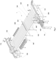
- an accumulator is depicted, which is generally indicated with 1, it comprises a diverter apparatus 100 configured to deviate a flow of articles 500 from a conveyor 110, 120 to a plurality of accumulating/transferring channels 130 of said articles 500.
- conveyor 110, 120 both the input conveyor belt 110 for supplying the articles 500 to the accumulating/transferring channels 130, and the output conveyor belt 120 for evacuating the articles 500 from the accumulating/transferring channels 130 are meant.
- said articles 500 e.g., bottles, cans, vases, glasses, bricks, and more generally containers, pass onto conveyors that are part of lines adapted to the production and/or filling and/or packaging and/or storage of said articles 500.
- the production and/or filling and/or packaging and/or storage machines, of said lines may have downtimes for the replenishment of consumables, or for short maintenances; these stops of the single machines, if prolonged, may cause consequent stops of the production line, thus compromising its productivity.
- Said accumulators 1 of articles 500 must be able to contain the articles 500 processed by the machines upstream, during the downtime of the machines downstream, subsequently returning the articles 500 to the line upon the re-start of the above-mentioned machines downstream.
- the diverter apparatus 100 diverts the flow of articles 500 on a plurality of accumulating/transferring channels 130, when the machines downstream the accumulator 1 are inactive.
- the accumulator 1 depicted in Fig. 1 is only an example of a possible application of the diverter apparatus 100.
- said diverter apparatus 100 can be used also as a partitioner, in which a row of articles 500 is divided into a plurality of rows, and vice versa.
- the diverter apparatus 100 operating as a partitioner transfers the articles 500, arranged on a row 501 dividing them into a plurality of transferring channels 130 and arranging them on multiple parallel rows 501.
- the implementation examples of said plurality of accumulating/transferring channels 130 that is described herein below is intended as non-limiting with reference to the attached drawings.
- Said accumulating/transferring channels 130 can be considered both those of an accumulator 1, as depicted in Fig. 1 , and those of a partitioner not specifically depicted in the Figure.
- Said plurality of accumulating/transferring channels 130 can be achieved by a plurality of conveyors placed side by side or preferably, as depicted in Fig. 1 , it can be achieved by a single accumulation/transferring table 130'.
- Said table 130' is configured to arrange and transfer the articles 500 according to a plurality of mutually parallel rows 501.
- the accumulation/transferring table 130' may comprise a structure with multiple accumulation/transferring chains 135 arranged mutually parallel.
- Each accumulation/transferring chain 135 defines the accumulating/transferring channel 130.
- Fig. 1 shows a number of accumulation/transferring chains 135, although any other amount can be devised, this depending on the accumulation/transfer ability that is required by the line.
- said accumulation/transferring chains 135 advance independently one of another, so that each di them is able to receive and evacuate a single row 501 of articles 500, independently of the other ones.
- Fig. 1 a possible embodiment is depicted, in which the table 130' provides for a plurality of towing means 136, in which each is operatively connected to a single accumulation/transferring chain 135 to carry out the handling thereof.
- accumulation channels 130 In order not to be constrained by the construction form of the accumulation/transferring zone, reference will be generally made to accumulation channels 130 herein below.
- said input 110, or output 120 conveyor is arranged orthogonal to the accumulating/transferring channels 130, i.e., so that the articles advancing direction 500 on the conveyor 110, 120 is orthogonal to the articles advancing direction 500 on the accumulating/transferring channels 130.
- the input 110 and/or output 120 conveyor comprises an advancing chain 111, 121 of a type known to those skilled in the art; preferably said advancing chain 111, 121 extends across the entire width of the accumulating/transferring channels 130, as depicted in Fig. 1 .
- Said articles 500 passing from the input conveyor 110 to the accumulating/transferring channels 130, or from the accumulating/transferring channels 130 to the output conveyor 120, are preferably diverted by 90°.
- FIG. 1 an axonometric view of an accumulator 1 is depicted, onto which a diverter apparatus 100 is installed on both the input conveyor 110 and the output conveyor 120.
- the diverter apparatus 100 is movable along the conveyor 110, 120 so that it is able to transfer such articles 500 between the conveyor 110, 120 and any one of the accumulating/transferring channels 130.
- Said diverter apparatus 100 is configured to preferably divert the articles 500 by 90°, passing from the conveyor 110 120 to the accumulating/transferring channels 130.
- Said diverter apparatus 100 preferably comprises an outer device 200 and an inner device 300.
- the outer device 200 and the inner device 300 are positioned so as to define a transferring channel 400 for the passage of the articles 500.
- Said outer device 200 and inner device 300 are configurated to define the transferring channel 400 so as to divert the articles by an angle of preferably 90°.
- the outer device 200 and the inner device 300 translate along the conveyor 110, 120 so as to arrange the transferring channel 400 in communication with each accumulating/transferring channel 130.
- the outer device 200 and the inner device 300 are positioned so that the transferring channel 400 is centered on the advancing chains 111, 112.
- the outer device 200 and the inner device 300 are preferably positioned so that the transferring channel 400 is centered with the accumulating/transferring channel 130.
- the outer device 200 and the inner device 300 translate together.
- the outer device 200 and the inner device 300 are mechanically connected with the same translating devices of the diverter apparatus 100.
- Said translating devices can be located below, or above the conveyor 110, 120.
- Said translating devices can comprise at least one motor or gearmotor transmitting the motion to transmission members, such as pulleys and belts, or pinions and chains, etc.
- Said translating devices can further comprise members to keep the outer device 200 and the inner device 300 in guidance during translation.
- said outer device 200 and/or inner device 300 comprises an adjusting device 210, 310 to change the size of said transferring channel 400 and adapt it to the article 500 size.
- an adjusting device 210, 310 allows adjusting the size of the transferring channel 400 without having to replace components.
- said outer device 200 and said inner device 300 comprise respective engagement surfaces 201, 301, which are mutually opposite.
- the engagement surface 201, of the outer device 200 and the engagement surface 301, of the outer device 300 respectively define an outer side wall 410 and an inner side wall 420 of the transferring channel 400, which are adapted to engage on the body of said articles 500.
- the outer side wall 410 and the inner side wall 420 contact the body of the article to guide it in passing from the conveyor 110, 120 to the accumulating/transferring channel 130.
- said engagement surface 201 of the outer device 200 and/or said engagement surface 301 of the inner device 300 is operatively associated to the adjusting device 210, 310, in particular to translate said outer and/or inner side walls 410, 420 closer to/farther from one another.
- it can translate only the engagement surface 201 of the outer device 200 or only the engagement surface 301 of the inner device 300, or both.
- a preferred solution provides for moving both the engagement surfaces 201, 301, while keeping the axis of the transferring channel 400 in a stationary position.
- the transferring channel 400 remains centered on the advancing chains 111, 112 and/or on the accumulating/transferring channel 130.
- the adjustment occurs by bringing only the engagement surfaces 201 and/or 301 closer to/farther from one another, which reduces the times and stresses involved.
- Said engagement surface 201 of the outer device 200 and/or said engagement surface 301 of the inner device 300 can comprise both rectilinear surface portions 201', 301' and/or curvilinear surface portions 201", 301".
- the configuration can depend, for example, on the distance and/or kind of the conveyors 110, 120 and the accumulating/transferring channels 130.
- the engagement surface 201 of the outer device 200 is preferably divided into at least one input sector 201a, and an output sector 201b, each comprising at least one curvilinear surface portion 201" preferably adjacent to one or more rectilinear surface portions 201'.
- a non-binding embodiment of the outer device 200 is depicted, in which the engagement surface 201, from the input to the output, provides, in sequence, a first rectilinear surface portion 201', a second curvilinear surface portion 201", a third rectilinear surface portion 201', a fourth curvilinear surface portion 201", and a fifth rectilinear surface portion 201'.
- the engagement surface 301 of the outer device 300 is preferably divided into at least one input sector 301a, and an output sector 301b, each comprising at least one curvilinear surface portion 301" preferably adjacent to one or more rectilinear surface portions 301'.
- a non-binding embodiment of the inner device 300 is depicted, in which the engagement surface 301, from the input to the output, provides, in sequence, a first rectilinear surface portion 301', a first curvilinear surface portion 301", a second rectilinear surface portion 301', a second curvilinear surface portion 301", and a third rectilinear surface portion 301'.
- the curvilinear surface portions 201" are preferably concave.
- the curvilinear surface portions 301" are preferably convex.
- the convex curvilinear surface portions 301" of the inner device 300 face the concave curvilinear surface portions 201" of the outer device 200.
- the rectilinear surface portions 301' of the inner device 300 preferably face the rectilinear surface portions 201' of the outer device 200.
- the curvilinear portions 201", 301" are preferably portions of a circumference.
- Some of said adjacent rectilinear 201', 301' or curvilinear 201", 301" surface portions can preferably be mechanically connected to one another.
- the adjusting device 210, 310 is configured so that the opposite curvilinear surface portions 201", 301" and all of the opposite rectilinear surface portions 201', 301' of the opposite input sectors 201a, 301a translate closer to/farther from one another along an input direction X parallel to the straight line that joins the centers of the opposite curvilinear surfaces 201", 301".
- the opposite curvilinear surface portions 201", 301" and all of the opposite rectilinear surface portions 201', 301' of the opposite output sectors 201b, 301b translate closer to/farther from one another along an output direction X' parallel to the straight line that joins the centers of the opposite curvilinear surfaces 201", 301".
- the input sector 201a, 301a and the output sector 201b, 301b translate according to the bisector of the angle subtended by the curvilinear surface portion 201", 301", in particular circumference, comprised therein.
- the translation of the input sector 201a, 301a, and the output sector 201b, 301b along the input X and output X' directions also entails an elongation/shortening of said engagement surface 201, 301 in an articles advancing direction 500 due to the fact that the input sector 201a, 301a moves closer to/farther from the output sector 201b, 301b in an articles advancing direction 500.
- the engagement surface 201 of the outer device 200 and the engagement surface 301 of the inner device 300 are not movable in the product advancing direction.
- a second alternative solution can provide for the engagement surface 201 of the outer device 200 not to be movable, while the engagement surface 301 of the inner device 300 is movable in a product advancing direction, or vice versa.
- the engagement surface 201 of the outer device 200 and the engagement surface 301 of the inner device 300 are movable in the product advancing direction.
- the first solution is simpler and less expensive, and the engagement surface 201, 301 does not go with the articles 500 during the transfer thereof, i.e., the articles 500 crawl against the engagement surface 201, 301 during the transfer between conveyor 110, 120 and accumulating/transferring channels 130.
- the third solution is more complex, yet more reliable, whereby both the engagement surfaces 201, 301 translate according to the advancing direction of the article 500. In such a case, the engagement surfaces 201, 301 accompany the articles 500 during the transfer thereof.
- the articles 500 do not crawl against the engagement surface 201, 301 during the transfer between conveyor 110, 120 and accumulating/transferring channels 130, since said engagement surface 201, 301 moves integrally with said articles 500 going with them during said transfer.
- the outer device 200 and/or inner device 300 comprises advancing means 220, 320.
- Said advancing means 220, 320 are operatively associated to said engagement surface 201 of the outer device 200 and/or to said engagement surface 301 of the inner device 300.
- said engagement surface 201 of the outer device 200 and/or said engagement surface 301 of the inner device 300 accompanies the article 500, moving with it, during the transit inside the diverter apparatus 100.
- the advancing means 220 of the outer device 200 are preferably independent of the advancing means 320 of the inner device 300 and are preferably configured to be able to be managed in s related manner.
- a preferred embodiment of advancing of said engagement surface 201 of the outer device 200 and/or of said engagement surface 301 of the inner device 300 is described herein below and depicted in the Figures.
- said outer device 200 and/or said inner device 300 comprises a flexible member 202, 302.
- a portion of said flexible member 202', 302' faces inwardly relative to the transferring channel 400 and defines said engagement surface 201 of the outer device 200 and/or said engagement surface 301 of the inner device 300.
- Said flexible member 202, 302 preferably has a closed loop configuration, as outlined in the Figures.
- the advancing means 220 of the outer device 200 are operatively associated to said flexible member 202 of the outer device 200.
- the advancing means 320 of the inner device 300 and/or are also preferably operatively associated to said flexible member 302 of the inner device 300.
- the handling direction is such that the portion of said flexible member 202', 302' facing inwardly of the transferring channel 400 moves in an articles advancing direction 500.
- the flexible member 202 of the outer device 200 will rotate clockwise, and the flexible member 302 of the outer device 300 will rotate counterclockwise, or vice versa.
- the flexible member 202 of the outer device 200 and the flexible member 302 of the inner device 300 have different advancing speeds, to make so that the article 500 advances without rotating about a symmetry axis thereof.
- the advancing means 220, of the outer device 200 are preferably mechanically independent of the advancing means 320 of the inner device 300.
- the operation of the advancing means 220, of the outer device 200 and the advancing means 320 of the inner device 300 is operatively related, to make so that the article 500, which is in contact with the flexible members 202, 302, advances without rotating.
- This operation is particularly advantageous when the articles 500 have a non-axisymmetric configuration and need a well-defined advancement orientation.
- the outer device 200 preferably comprises tensioning means 204, which engage on the flexible member 202.
- tensioning means 204, 304 it is possible to compensate the elongation/shortening of the flexible member 202, 302, when the outer 410 and/or inner 420 side walls of the transferring channel 400 are displaced to carry out the format change.
- the flexible member 202, 302 presses onto the tensioning means 204, 304 to recover the length it requires to reach the new position.
- Said tensioning means 204, 304 can have an operation of a pneumatic, hydraulic, or spring type, etc.
- tensioning means 204, 304 will be not described in detail, since they are known to those skilled in the art, and all of them fall within the protection scope of the invention.
- An embodiment provides for, in the outer device 200 and/or the inner device 300, that the flexible member 202, 302 is a toothed belt.
- the advancing means 220, 320 can comprise a pulley operatively associated to a motor or gearmotor.
- the toothed belt is preferably positioned so that the part facing inwardly of the transferring channel 400, i.e., the surface contacting the articles 500 is smooth and not toothed.
- An alternative embodiment provides for, in the outer device 200 and/or the inner device 300, that the flexible member 202, 302 is a modular chain, for instance, the types used for conveyor belts.
- the advancing means 220, 320 can comprise a pinion or crown operatively associated to a motor or gearmotor.
- the most suitable flexible member 202, 302 mainly depends on the type of articles 500 to be transferred.
- an embodiment is depicted, which provides for, in the outer device 200, that the flexible member 202 is a modular chain, and in the inner device 300, the flexible member 302 is a strap.
- said flexible member 202 of the outer device 200 and/or said flexible member 302 of the inner device 300 preferably has a surface contacting the articles 500 of a deformable type.
- the flexible member 202, 302 may have a contact surface provided with rubber or foam, etc.
- an embodiment which provides for the modular chain of the outer device 200 comprises rubberised dowels to optimise the contact with the articles 500.
- said outer device 200 and/or said inner device 300 comprise a guide member 203, 303, onto which the flexible member 202, 302 rests.
- said guide member 203, 303 is at least positioned at the portion of said flexible member 202', 302' defining the engagement surface 201 of the outer device 200 and/or the engagement surface 301 of the inner device 300.
- the guide member 203 of the outer device 200 and/or the guide member 303 of the inner device 300 is operatively associated to the adjusting device 210 of the outer device 200 and/or to the adjusting device 310 of the inner device 300 to narrow/broaden the transferring channel 400.
- the handling of the guide member 203 of the outer device 200 and/or of the guide member 303 of the inner device 300 causes at least the portion of said flexible member 202', 302' defining the engagement surface 201 of the outer device 200 and/or the engagement surface 301 of the inner device 300 to move.
- a preferred embodiment provides that the guide member 203 of the outer device 200 and/or the guide member 303 of the inner device 300 comprises rectilinear guide portions 203', 303' and/or curvilinear guide portions 203", 303".
- said rectilinear guide portions 203', 303' define the rectilinear surface portions 201', 301'
- said curvilinear guide portions 203", 303" define the curvilinear surface portions 201", 301" of the engagement surface 201 of the outer device 200 and of the engagement surface 301 of the inner device 300
- Some of said adjacent rectilinear guide portions 203', 303' and/or curvilinear guide portions 203", 303" can preferably be mechanically connected to one another in a locked manner and form a single guide assembly.
- some of said rectilinear guide portions 203', 303' and/or curvilinear guide portions 203", 303" are preferably mechanically connected to the adjacent ones in a free or movable manner, to allow the elongation/shortening of the engagement surface 201 of the outer device 200 and/or the engagement surface 301 of the inner device 300.
- some of the rectilinear guide portions 203', 303' and/or curvilinear guide portions 203", 303" are fully unconstrained one relative to the other.
- the movement between adjacent portions allows the displacement of the guide member 203 of the outer device 200 and/or of the guide member 303 of the inner device 300, to narrow/broaden the transferring channel 400.
- This movement involves not only an approaching/moving away of the guide member 203 of the outer device 200 relative to the guide member 303 of the inner device 300, but it also entails an elongation of the engagement surface 201, 301.
- the displacement of the guide member 203 of the outer device 200 and/or of the guide member 303 of the inner device 300 involves a displacement of that portion of said flexible member 203', 302' which is in a resting position.
- the outer device 200 comprises an input guide assembly 203a, and an output guide assembly 203b which define the input sector 201a, and the output sector 201b.
- each input 203a, and/or output 203b guide assembly comprises at least one curvilinear guide portion 203" preferably adjacent to one or more rectilinear guide portions 203'.
- an input 203a, and/or output 203b guide assembly is depicted, which comprises in sequence a rectilinear guide portion 203', a curvilinear guide portion 203", and a rectilinear guide portion 203' mechanically integral to one another to form a single guide.
- a rectilinear guide portion 203' can be present between the input guide assembly 203a, 203b.
- the inner device 300 comprises an input guide assembly 303a, and an output guide assembly 303b, which respectively define the input sector 301a, and the output sector 301b.
- each input 303a, and/or output 303b guide assembly comprises at least one curvilinear guide portion 303" preferably adjacent to one or more rectilinear guide portions 303'.
- an input 303a, and/or output 303b guide assembly is depicted, which comprises in sequence a rectilinear guide portion 303', a curvilinear guide portion 303", and a rectilinear guide portion 303' mechanically integral to one another to form a single guide.
- a rectilinear guide portion 303' can be present between the input 303a, and the output 303b guide assembly.
- the curvilinear guide portions 203" are preferably concave.
- the curvilinear guide portions 303" are preferably convex.
- the convex curvilinear guide portions 303" of the inner device 300 are opposite the concave curvilinear guide portions 203" of the outer device 200.
- the rectilinear guide portions 303' of the inner device 300 are preferably opposite the rectilinear guide portions 203' of the outer device 200.
- the curvilinear guide portions 203", 303" are preferably portions of a circumference.
- the adjusting device 210, 310 is configured so that the opposite curvilinear guide portions 203", 303" and all of the opposite rectilinear guide portions 203', 303' of the opposite input guide assemblies 203a, 303a translate closer to/farther from one another along the input direction X parallel to the straight line that joins the centers of the opposite curvilinear guides 203", 301".
- the opposite curvilinear guide portions 203", 303" and all of the opposite rectilinear guide portions 203', 303' of the opposite output guide assemblies 203b, 303b translate closer to/farther from one another along the output direction X' parallel to the straight line that joins the centers of the opposite curvilinear guides 203", 303".
- the input guide assembly 203a, 303a and the output guide assembly 203b, 303b translate according to the bisector of the angle subtended by the curvilinear guide portion 203", 303", in particular circumference, comprised therein.
- the translation of the input guide assembly 203a, 303a, and of the output guide assembly 203b, 303b along the input X and output X' direction also entails an elongation/shortening of the engagement surface 201, 301 in an articles advancing direction 500 due to the fact that the input guide assembly 203a, 303a, moves closer to/farther from the output guide assembly 203b, 303b in an articles advancing direction 500.
- a gap can be formed between the input guide assembly 203a, 303 and the output guide assembly 203b, 303b, in particular when the transferring channel 400 narrows, but said gap does not cause any problems to the transit of the articles 500, since it is covered by the flexible member 202', 302'.
- the adjusting device 210, 310 comprises actuating means 211, of the outer device 200 and/or actuating means 311, of the inner device 300.
- Said actuating means 211, 311 are configured to move and lock in position the engagement surface 201 of the outer device 200 and/or the engagement surface 301 of the inner device 300.
- Said actuating means 211, 311 are preferably automatic, for example, of the electrical or pneumatic type.
- This solution allows changing the dimension of the transferring channel 400 in an automatized manner, preferably a recipe, as a function of the size of the article 500 to be processed.
- said actuating means 211, 311 can be of a manual type, e.g., handles or small steering wheels, to implement a functional, yet less expensive, solution, as depicted in the Figure.
- Said actuating means 211, 311 are shaped so as to operate on the guide member 203, 303 in particular on the input 203a, 303a, and output 203b, 303b guide assemblies so as to change the dimension of the transferring channel 400 to get the same dimension at all points, thus ensuring the proper guide of the article 500.
- Said actuating means 211 are configured so as to concomitantly move and/or lock all the input 203a, and output 203b, guide assemblies of the outer device 200.
- Said actuating means 311 are configured so as to concomitantly move and/or lock all the input 303a, and output 303b, guide assemblies of the outer device 300.
- actuating means 211, 311 comprise an angle drive 211a, 311a operatively connected to an engine or a handle 211b, 311b.
- Said angle drive 211a, 311a sets a driving member 211c, 311c in motion.
- the driving member 211c, 311c is mechanically and operatively connected to all the input 203a, 303a, and output 203b, 303b guide assemblies, and/or rectilinear guide portions 203', 303' and/or curvilinear guide portions 203", 303".
- said driving member 211c, 311c preferably comprises a pin 211d, 311d projecting from the angle drive 211a, 311a which is put in rotation thereby.
- Said driving member 211c, 311c may comprise joints and/or junctions 211e, 311e to reach all the input 203a, 303a, and output 203b, 303b guide assemblies, and/or rectilinear guide portions 203', 303' and/or curvilinear guide portions 203", 303" to be moved.
- said driving member 211c, 311c may also comprise motion transformation means 211f, 311f, such as rods and connecting rods, to transform the rotational motion of the pin 211d, 311d into a rectilinear motion of the guide member 203, 303.
- motion transformation means 211f, 311f such as rods and connecting rods
- the adjusting device 210, 310 may comprise one or more positioning members 212 to allow a guided translation of the guide member 203, 303, in particular of all the input 203a, 303a, and output 203b, 303b guide assemblies, and/or rectilinear guide portions 203', 303' and/or curvilinear guide portions 203", 303".
- Said positioning members 212 are preferably configurated so as to allow the displacement of the input guide assembly 203a, 303a, in an input direction X, and/or of the output guide assembly 203b, 303b in an output direction X'.
- said one or more positioning members 212 mechanically associated to the input guide assemblies 203a, 303a, are arranged parallel to the direction X.
- said one or more positioning members 212 mechanically associated to the output guide assemblies 203b, 303b are arranged parallel to the direction X.
- Object of the invention is also the accumulator 1 comprising at least one conveyor 110, 120, and a plurality of accumulating/transferring channels 130 onto which a diverter apparatus 100 operates, adapted to divert a flow of articles 500 from the conveyor 110, 120 to the plurality of accumulating/transferring channels 130, and vice versa, in which said diverter apparatus 100 is made according to the characteristics described above.
- Object of the invention is also a partitioner comprising at least one conveyor 110, 120, and a plurality of accumulating/transferring channels 130 onto which a diverter apparatus 100 operates, adapted to divert a flow of articles 500 from the conveyor 110, 120 to the plurality of accumulating/transferring channels 130, and vice versa, in which said diverter apparatus 100 is made according to the characteristics described above.
Landscapes
- Engineering & Computer Science (AREA)
- Mechanical Engineering (AREA)
- Branching, Merging, And Special Transfer Between Conveyors (AREA)
Abstract
Description
- The present invention relates to the field of systems for the accumulation/transfer of articles such as, for example bottles, cans, vases, glasses, bricks, and more generally containers, in lines adapted to the production and/or filling and/or packaging and/or storage of said articles.
- The production and/or filling and/or packaging and/or storage lines of containers comprise a plurality of machines arranged according to a sequence imposed by the production/filling/ packaging process (e.g., blowing, filling, labelling, palletizing machine, etc.).
- Said machines are connected to each other by conveyor belts that allow the transit of said articles, from a machine to the next one. During operation, said machines may have downtimes for the replenishment of consumables, or for short maintenances; these stops of the single machines, if prolonged, may cause consequent stops of the production line, thus compromising its productivity.
- In order to avoid this problem, action is taken by creating articles accumulation/transfer zones, between a machine and the next one.
- Said articles accumulation/transfer zones must be able to contain the articles processed by the machines upstream, during the downtime of the machines downstream.
- Generally, said accumulated articles are returned to the line upon the re-start of the above-mentioned machines downstream.
- Different kinds of accumulation devices are known to the state of the art.
- For example, there are accumulation devices that comprise a supply conveyor, an accumulation table, and an output conveyor. The accumulation table may comprise multiple storage paths, i.e., multiple parallel conveyors.
- A first diverter apparatus brings the products or articles, from the supply conveyor to the accumulation table, and in particular, time after time, to one of the parallel conveyors.
- A second diverter apparatus brings the products or articles, from the accumulation table, in particular, time after time, from the parallel conveyors, to the output conveyor.
- The transiting articles have to be guided and preferably accompanied towards the accumulation table or the output conveyor.
- Therefore, said diverter apparatus is movable along the supply or output conveyor so as to arrange the transferring channel in communication with each accumulation channel.
- The diverter apparatus generally comprises an outer device and an inner device, arranged so as to define a transferring channel for the passage of the articles.
- The outer device and the inner device each comprise a respective engagement surface opposite one another, which respectively define an inner and an outer side walls of the transferring channel, which are adapted to engage on the body of said articles.
- The diverter apparatus can be of a simple, unexpensive type, i.e., with the engagement surface of the outer device and the engagement surface of the inner device that is not movable in the product advancing direction.
- Or, the diverter apparatus can be of a more complex type, i.e., with the engagement surface of the outer device and the engagement surface of the inner device of a movable type in the product advancing direction.
- In such a case, said engagement surfaces are generally straps that translate in the product transferring direction.
- Both the diverter apparatus of a simpler and more complex types has to be able to work with articles that differ both in shape and size.
- In particular, the engagement surfaces have to be configurated so as to remain in contact with the article during the transit inside the diverter apparatus.
- Since the engagement surfaces are of a complex shape, and generally provide for both rectilinear and curvilinear lengths, a format change provides for the replacement of one or more components.
- In fact, solutions are known, whereby, upon an article change, provide for a format change, which involves replacing the whole apparatus with an apparatus that is suitable to the new article, or may involve the replacement of one of the two, inner or outer, devices.
- For example, document
EP4041662 describes a simplified format change which provides for the replacement of a portion of the inner device. - Therefore, the known format changes have the drawback of requiring a plurality of replacement equipment.
- Especially in the case that the production line has to process may different kinds of articles, equipment for each type of article needs to be provided.
- In the case that new types of articles have to be processed, it is necessary to purchase new equipment.
- Furthermore, as a result, a format change of a known type may require long downtimes of the articles accumulation zone in order to perform the replacement of the various equipment.
- A further drawback is related to the fact that said format change operation cannot be performed automatically, and it always has to be performed by an operator.
- The technical problem underlying the present invention is to provide to the art an improved diverter apparatus that is structurally and functionally devised to overcome one or more of the limitations set forth above with reference to the mentioned prior art.
- Within the scope of the above-mentioned problem, a main object of the invention is to develop a diverter apparatus that allows processing different types of articles passing from one to the other in a simple and quick manner.
- A further object of the invention is also to provide to the art a diverter apparatus within the scope of a solution that makes the format change easier.
- Object of the present invention is also to allow making a diverter apparatus that does not require the presence of an operator for a format change.
- In particular, it is an object of the invention a diverter apparatus adapted to divert a flow of articles from a conveyor to a plurality of accumulating/transferring channels, and vice versa.
- Said diverter apparatus preferably comprises an outer device and an inner device arranged so as to define a transferring channel for the passage of the articles.
- Said diverter apparatus is preferably movable along the conveyor so as to arrange the transferring channel in communication with each accumulating/transferring channel.
- In particular, said outer device and/or inner device comprises an adjusting device to change the size of said transferring channel and adapt it to the article size.
- Said outer device and said inner device preferably comprise a respective engagement surface which are mutually opposite, which respectively define an outer and an inner side walls of the transferring channel, which are adapted to engage on the body of said articles.
- Said engagement surface of the outer device and/or said engagement surface of the inner device is preferably operatively associated to the adjusting device to translate said outer and/or inner side walls closer to/farther from one another.
- Said engagement surface of the outer device and/or said engagement surface of the inner device preferably comprises at least one input sector and one output sector, each comprising at least one curvilinear surface portion and preferably one or more rectilinear surface portions adjacent thereto.
- Preferably, the curvilinear surface portion is a portion of a circumference.
- The adjusting device is preferably adapted to translate the opposite input sectors closer to/farther from one another along an input direction parallel to the straight line that joins the centres of the respective opposite curvilinear surfaces.
- The adjusting device is preferably adapted to translate the opposite output sectors closer to/farther from one another along an output direction parallel to the straight line that joins the centres of the respective opposite curvilinear surfaces.
- Said outer device and/or inner device preferably comprises advancing means that are operatively associated to said engagement surface of the outer device and/or to said engagement surface of the inner device to move said outer and/or inner side walls of the transferring channel in an articles advancing direction.
- Said outer device and/or said inner device preferably comprises a flexible member, in which a portion of said flexible member faces inwardly relative to the transferring channel and defines said engagement surface of the outer device and/or said engagement surface of the inner device.
- Said flexible member preferably has a closed loop configuration.
- The advancing means of the outer device and/or of the inner device are preferably operatively associated to said flexible member of the outer device and/or to said flexible member of the inner device for the movement thereof, in particular to advance endlessly in an articles advancing direction.
- The advancing means of said flexible member of the outer device and the advancing means of said flexible member of the inner device can preferably vary their advancing speed independently of one another.
- Said outer device and/or said inner device preferably comprises a guide member onto which the flexible member rests, in particular at the portion of said flexible member defining the engagement surface of the outer device and/or the engagement surface of the inner device.
- The guide member of the outer device and/or the guide member of the inner device is preferably operatively associated to the adjusting device of the outer device and/or to the adjusting device of the inner device to narrow/broaden the transferring channel.
- The outer device and/or the inner device preferably comprise tensioning means that engage on the flexible member of the outer device and/or on the flexible member of the inner device to compensate for its elongation/shortening, when the guide member of the outer device and/or the guide member of the inner device moves to narrow/broaden the transferring channel.
- The guide member of the outer device and/or the guide member of the inner device preferably comprises an input guide assembly and an output guide assembly, each comprising at least one curvilinear guide portion and preferably one or more rectilinear guide portions adjacent thereto.
- The adjusting device of the outer device and/or the adjusting device of the inner device is preferably adapted to translate the opposite output guide assemblies closer to/farther from one another along the input direction parallel to the straight line that joins the centres of the respective opposite curvilinear guides and/or is adapted to translate the opposite output guide assemblies translating them closer to/farther from one another along the output direction parallel to the straight line that joins the centres of the respective opposite curvilinear guides.
- The adjusting device of the outer device and/or the adjusting device of the inner device preferably comprises actuating means, of the outer device and/or actuating means, of the inner device of an automatic type, for example, of the electrical or pneumatic type, or of a manual type, e.g., handles or small steering wheels.
- It is an object of the invention also an accumulator comprising at least one conveyor and a plurality of accumulating/transferring channels onto which a diverter apparatus operates, which is adapted to divert a flow of articles from the conveyor to the plurality of accumulating/transferring channels, and vice versa, in which said diverter apparatus is made according to the preceding features.
- Such and other objects are achieved by virtue of the characteristics of the invention that are set forth in the independent claims. The dependent claims outline preferred and/or particularly advantageous aspects of the invention.
- Said objects and advantages are all achieved by the diverter apparatus, which is the subject-matter of the present invention, which is characterized by what is provided for in the claims set forth below.
- This and other characteristics will be further highlighted by the following description of some embodiments, illustrated purely by way of example and not by way of limitation in the attached drawing tables.
-
Fig. 1 : illustrates an axonometric view of an accumulator with diverter apparatus, accumulation table, input and output conveyors; -
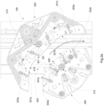
Fig. 2a : illustrates a plan view of the diverter apparatus; -
Fig. 2b : illustrates an axonometric view of the diverter apparatus; -
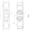
Fig. 3a : illustrates a plan view of the inner device; -
Fig. 3b : illustrates a side view of the inner device; -
Fig. 3c : illustrates an axonometric view of the inner device; -
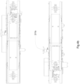
Fig. 4a : illustrates a plan view of the outer device; -
Fig. 4b : illustrates a side view of the outer device; -
Fig. 4c : illustrates an axonometric view of the outer device. - With reference to
Fig. 1 , an accumulator is depicted, which is generally indicated with 1, it comprises adiverter apparatus 100 configured to deviate a flow ofarticles 500 from aconveyor channels 130 of saidarticles 500. - By the
term conveyor input conveyor belt 110 for supplying thearticles 500 to the accumulating/transferringchannels 130, and theoutput conveyor belt 120 for evacuating thearticles 500 from the accumulating/transferringchannels 130 are meant. - In particular, said
articles 500, e.g., bottles, cans, vases, glasses, bricks, and more generally containers, pass onto conveyors that are part of lines adapted to the production and/or filling and/or packaging and/or storage of saidarticles 500. - During operation, the production and/or filling and/or packaging and/or storage machines, of said lines, may have downtimes for the replenishment of consumables, or for short maintenances; these stops of the single machines, if prolonged, may cause consequent stops of the production line, thus compromising its productivity.
- In order to avoid this problem, action is taken by creating articles accumulation/
transfer zones 500, inserting accumulators 1 between a machine and the next one. - Said accumulators 1 of
articles 500 must be able to contain thearticles 500 processed by the machines upstream, during the downtime of the machines downstream, subsequently returning thearticles 500 to the line upon the re-start of the above-mentioned machines downstream. - In particular, the
diverter apparatus 100 diverts the flow ofarticles 500 on a plurality of accumulating/transferringchannels 130, when the machines downstream the accumulator 1 are inactive. - The accumulator 1 depicted in
Fig. 1 is only an example of a possible application of thediverter apparatus 100. - In fact, said
diverter apparatus 100 can be used also as a partitioner, in which a row ofarticles 500 is divided into a plurality of rows, and vice versa. - In fact, in the production and/or filling and/or packaging and/or storage lines between a machine and the next one, it can be necessary to vary the number of rows of articles entering a machine to accommodate the number of supply channers for which said machine is configured.
- The
diverter apparatus 100 operating as a partitioner transfers thearticles 500, arranged on arow 501 dividing them into a plurality of transferringchannels 130 and arranging them on multipleparallel rows 501. The implementation examples of said plurality of accumulating/transferringchannels 130 that is described herein below is intended as non-limiting with reference to the attached drawings. - Said accumulating/transferring
channels 130 can be considered both those of an accumulator 1, as depicted inFig. 1 , and those of a partitioner not specifically depicted in the Figure. - Said plurality of accumulating/transferring
channels 130 can be achieved by a plurality of conveyors placed side by side or preferably, as depicted inFig. 1 , it can be achieved by a single accumulation/transferring table 130'. - Said table 130' is configured to arrange and transfer the
articles 500 according to a plurality of mutuallyparallel rows 501. - As shown in
Fig. 1 , the accumulation/transferring table 130' may comprise a structure with multiple accumulation/transferringchains 135 arranged mutually parallel. - Each accumulation/
transferring chain 135 defines the accumulating/transferringchannel 130. -
Fig. 1 shows a number of accumulation/transferringchains 135, although any other amount can be devised, this depending on the accumulation/transfer ability that is required by the line. - According to a preferred embodiment, said accumulation/transferring
chains 135 advance independently one of another, so that each di them is able to receive and evacuate asingle row 501 ofarticles 500, independently of the other ones. - In
Fig. 1 , a possible embodiment is depicted, in which the table 130' provides for a plurality of towing means 136, in which each is operatively connected to a single accumulation/transferring chain 135 to carry out the handling thereof. - In order not to be constrained by the construction form of the accumulation/transferring zone, reference will be generally made to
accumulation channels 130 herein below. - As depicted in
Fig. 1 , saidinput 110, oroutput 120 conveyor is arranged orthogonal to the accumulating/transferringchannels 130, i.e., so that thearticles advancing direction 500 on theconveyor articles advancing direction 500 on the accumulating/transferringchannels 130. - According to an aspect of the invention, the
input 110 and/oroutput 120 conveyor comprises an advancingchain 111, 121 of a type known to those skilled in the art; preferably said advancingchain 111, 121 extends across the entire width of the accumulating/transferringchannels 130, as depicted inFig. 1 . - Said
articles 500, passing from theinput conveyor 110 to the accumulating/transferringchannels 130, or from the accumulating/transferringchannels 130 to theoutput conveyor 120, are preferably diverted by 90°. - In
Fig. 1 , an axonometric view of an accumulator 1 is depicted, onto which adiverter apparatus 100 is installed on both theinput conveyor 110 and theoutput conveyor 120. - Herein below, when a
diverter apparatus 100 is referred to, reference will be made indistinctly to both the operative one at theinput conveyor 110 and theoutput conveyor 120 being structurally identical, even if not specular or simply rotated by 180°. - According to an aspect of the invention, the
diverter apparatus 100 is movable along theconveyor such articles 500 between theconveyor channels 130. - Said
diverter apparatus 100 is configured to preferably divert thearticles 500 by 90°, passing from theconveyor 110 120 to the accumulating/transferringchannels 130. - Said
diverter apparatus 100 preferably comprises anouter device 200 and aninner device 300. - In particular, the
outer device 200 and theinner device 300 are positioned so as to define a transferringchannel 400 for the passage of thearticles 500. - Said
outer device 200 andinner device 300 are configurated to define the transferringchannel 400 so as to divert the articles by an angle of preferably 90°. - In particular, the
outer device 200 and theinner device 300 translate along theconveyor channel 400 in communication with each accumulating/transferringchannel 130. - According to a preferred form, the
outer device 200 and theinner device 300 are positioned so that the transferringchannel 400 is centered on the advancingchains - The
outer device 200 and theinner device 300 are preferably positioned so that the transferringchannel 400 is centered with the accumulating/transferringchannel 130. - According to a preferred embodiment, the
outer device 200 and theinner device 300 translate together. - In particular, the
outer device 200 and theinner device 300 are mechanically connected with the same translating devices of thediverter apparatus 100. - Said translating devices can be located below, or above the
conveyor - Said translating devices can comprise at least one motor or gearmotor transmitting the motion to transmission members, such as pulleys and belts, or pinions and chains, etc.
- Said translating devices can further comprise members to keep the
outer device 200 and theinner device 300 in guidance during translation. - However, it is understood that what has been described above is of an exemplary, non-limiting value; in fact, a number of solutions exist, which those skilled in the art can identify in order to move, keep in guidance, and support the
diverter apparatus 100 at theconveyors - Therefore, possible detail variations that should be required for technical and/or functional reasons, are herefrom considered to fall within the same protection scope.
- It is an object of the invention that said
outer device 200 and/orinner device 300 comprises anadjusting device channel 400 and adapt it to thearticle 500 size. - This allows adapting the
diverter apparatus 100 to the different types of shape and size of thearticles 500. - The presence of an
adjusting device channel 400 without having to replace components. - According to an aspect of the invention, said
outer device 200 and saidinner device 300 comprise respective engagement surfaces 201, 301, which are mutually opposite. - In particular, the
engagement surface 201, of theouter device 200 and theengagement surface 301, of theouter device 300 respectively define anouter side wall 410 and aninner side wall 420 of the transferringchannel 400, which are adapted to engage on the body of saidarticles 500. - In particular, the
outer side wall 410 and theinner side wall 420 contact the body of the article to guide it in passing from theconveyor channel 130. - According to a preferred embodiment, said
engagement surface 201 of theouter device 200 and/or saidengagement surface 301 of theinner device 300 is operatively associated to theadjusting device inner side walls - According to possible embodiments, it can translate only the
engagement surface 201 of theouter device 200 or only theengagement surface 301 of theinner device 300, or both. - A preferred solution provides for moving both the engagement surfaces 201, 301, while keeping the axis of the transferring
channel 400 in a stationary position. - In such a manner, the transferring
channel 400 remains centered on the advancingchains channel 130. - This allows adjusting the
engagement surface 201 and/or 301 without having to move the entireouter device 200 and/or the entireinner device 300. - By virtue of this solution, the adjustment occurs by bringing only the engagement surfaces 201 and/or 301 closer to/farther from one another, which reduces the times and stresses involved.
- Said
engagement surface 201 of theouter device 200 and/or saidengagement surface 301 of theinner device 300 can comprise both rectilinear surface portions 201', 301' and/orcurvilinear surface portions 201", 301". - The configuration can depend, for example, on the distance and/or kind of the
conveyors channels 130. - The
engagement surface 201 of theouter device 200 is preferably divided into at least oneinput sector 201a, and anoutput sector 201b, each comprising at least onecurvilinear surface portion 201" preferably adjacent to one or more rectilinear surface portions 201'. - In particular, in the Figure a non-binding embodiment of the
outer device 200 is depicted, in which theengagement surface 201, from the input to the output, provides, in sequence, a first rectilinear surface portion 201', a secondcurvilinear surface portion 201", a third rectilinear surface portion 201', a fourthcurvilinear surface portion 201", and a fifth rectilinear surface portion 201'. - The
engagement surface 301 of theouter device 300 is preferably divided into at least oneinput sector 301a, and anoutput sector 301b, each comprising at least onecurvilinear surface portion 301" preferably adjacent to one or more rectilinear surface portions 301'. - In the Figure, also a non-binding embodiment of the
inner device 300 is depicted, in which theengagement surface 301, from the input to the output, provides, in sequence, a first rectilinear surface portion 301', a firstcurvilinear surface portion 301", a second rectilinear surface portion 301', a secondcurvilinear surface portion 301", and a third rectilinear surface portion 301'. - In the
outer device 200, thecurvilinear surface portions 201" are preferably concave. - In the
inner device 300, thecurvilinear surface portions 301" are preferably convex. - In particular, the convex
curvilinear surface portions 301" of theinner device 300 face the concavecurvilinear surface portions 201" of theouter device 200. - The rectilinear surface portions 301' of the
inner device 300 preferably face the rectilinear surface portions 201' of theouter device 200. - The
curvilinear portions 201", 301" are preferably portions of a circumference. - Some of said adjacent rectilinear 201', 301' or curvilinear 201", 301" surface portions can preferably be mechanically connected to one another.
- According to a preferred embodiment, the adjusting
device curvilinear surface portions 201", 301" and all of the opposite rectilinear surface portions 201', 301' of theopposite input sectors curvilinear surfaces 201", 301". - In the same manner, the opposite
curvilinear surface portions 201", 301" and all of the opposite rectilinear surface portions 201', 301' of theopposite output sectors curvilinear surfaces 201", 301". - In other words, the
input sector output sector curvilinear surface portion 201", 301", in particular circumference, comprised therein. - As a result, the translation of the
input sector output sector engagement surface articles advancing direction 500 due to the fact that theinput sector output sector articles advancing direction 500. - As regards the operative configuration of said
engagement surface 201 of theouter device 200 and/or saidengagement surface 301 of theinner device 300, particularly preferred embodiments can be provided for. - For instance, in a first solution, the
engagement surface 201 of theouter device 200 and theengagement surface 301 of theinner device 300 are not movable in the product advancing direction. - A second alternative solution can provide for the
engagement surface 201 of theouter device 200 not to be movable, while theengagement surface 301 of theinner device 300 is movable in a product advancing direction, or vice versa. - Alternatively, in a third solution, the
engagement surface 201 of theouter device 200 and theengagement surface 301 of theinner device 300 are movable in the product advancing direction. - The first solution is simpler and less expensive, and the
engagement surface articles 500 during the transfer thereof, i.e., thearticles 500 crawl against theengagement surface conveyor channels 130. - As will be better explained herein below, both with the first and the second solution, the orientation of the
articles 500 as the transferringchannel 400 dimensions change cannot be ensured. - The third solution is more complex, yet more reliable, whereby both the engagement surfaces 201, 301 translate according to the advancing direction of the
article 500. In such a case, the engagement surfaces 201, 301 accompany thearticles 500 during the transfer thereof. - In fact, the
articles 500 do not crawl against theengagement surface conveyor channels 130, since saidengagement surface articles 500 going with them during said transfer. - In order to achieve the solution with a
movable engagement surface outer device 200 and/orinner device 300 comprises advancing means 220, 320. - Said advancing means 220, 320 are operatively associated to said
engagement surface 201 of theouter device 200 and/or to saidengagement surface 301 of theinner device 300. - This allows moving said outer 410 and/or inner 420 side walls of the transferring
channel 400 in anarticles advancing direction 500. - Therefore, said
engagement surface 201 of theouter device 200 and/or saidengagement surface 301 of theinner device 300 accompanies thearticle 500, moving with it, during the transit inside thediverter apparatus 100. - This facilitates the advancement of the
article 500 in passing between theconveyor channels 130, and prevents thearticle 500 from being pushed by thearticles 500 upstream. - Furthermore, this prevents the
articles 500 from crawling on the outer 410 and/or inner 420 side walls of the transferringchannel 400. - These aspects ensure the integrity of the
articles 500 during the passage. - The advancing means 220 of the
outer device 200 are preferably independent of the advancing means 320 of theinner device 300 and are preferably configured to be able to be managed in s related manner. - This allows, as the dimensions of the transferring
channel 400 change, to manage the advancement of the engagement surfaces 201, 301 with different speeds, preferably related one to the other, to accommodate the new format of thearticles 500. - By virtue of this aspect, it is possible to keep the proper orientation of non-cylindrical products that need a constant, defined orientation.
- A preferred embodiment of advancing of said
engagement surface 201 of theouter device 200 and/or of saidengagement surface 301 of theinner device 300 is described herein below and depicted in the Figures. - In particular, said
outer device 200 and/or saidinner device 300 comprises aflexible member - In particular, a portion of said flexible member 202', 302' faces inwardly relative to the transferring
channel 400 and defines saidengagement surface 201 of theouter device 200 and/or saidengagement surface 301 of theinner device 300. - Said
flexible member - According to an advantageous aspect of the invention, the advancing means 220 of the
outer device 200 are operatively associated to saidflexible member 202 of theouter device 200. - The advancing means 320 of the
inner device 300 and/or are also preferably operatively associated to saidflexible member 302 of theinner device 300. - This allows the
flexible member channel 400 moves in anarticles advancing direction 500. - Therefore, since the
outer device 200 is opposite theinner device 300, theflexible member 202 of theouter device 200 will rotate clockwise, and theflexible member 302 of theouter device 300 will rotate counterclockwise, or vice versa. - Advantageously, the
flexible member 202 of theouter device 200 and theflexible member 302 of theinner device 300 have different advancing speeds, to make so that thearticle 500 advances without rotating about a symmetry axis thereof. - In fact, the advancing means 220, of the
outer device 200 are preferably mechanically independent of the advancing means 320 of theinner device 300. - Advantageously, the operation of the advancing means 220, of the
outer device 200 and the advancing means 320 of theinner device 300 is operatively related, to make so that thearticle 500, which is in contact with theflexible members - This operation is particularly advantageous when the
articles 500 have a non-axisymmetric configuration and need a well-defined advancement orientation. - Also the format change, i.e., the change in dimension of the transferring
channel 400, is made more efficient by the possibility to adjust the advancement speed of theflexible members 202 of theouter device 200, independently of the advancement speed of theflexible members 302 of theinner device 300, thus allowing to find the proper operation for each dimension and shape of anarticle 500. - The
outer device 200 preferably comprises tensioning means 204, which engage on theflexible member 202. - The
inner device 300 preferably comprises tensioning means 304, which engage on theflexible member 302 of theinner device 300. - By virtue of said tensioning means 204, 304, it is possible to compensate the elongation/shortening of the
flexible member channel 400 are displaced to carry out the format change. - In particular, when the transferring
channel 400 enlarges, theflexible member - Vice versa, when the transferring
channel 400 narrows, theflexible member - Said tensioning means 204, 304, can have an operation of a pneumatic, hydraulic, or spring type, etc.
- The several types of tensioning means 204, 304 will be not described in detail, since they are known to those skilled in the art, and all of them fall within the protection scope of the invention.
- An embodiment provides for, in the
outer device 200 and/or theinner device 300, that theflexible member - In such a case, the advancing means 220, 320 can comprise a pulley operatively associated to a motor or gearmotor.
- The toothed belt is preferably positioned so that the part facing inwardly of the transferring
channel 400, i.e., the surface contacting thearticles 500 is smooth and not toothed. - An alternative embodiment provides for, in the
outer device 200 and/or theinner device 300, that theflexible member - In such a case, the advancing means 220, 320 can comprise a pinion or crown operatively associated to a motor or gearmotor.
- The most suitable
flexible member articles 500 to be transferred. - In the Figure, an embodiment is depicted, which provides for, in the
outer device 200, that theflexible member 202 is a modular chain, and in theinner device 300, theflexible member 302 is a strap. - To improve adhesion and sliding friction, and to absorb the impact with the
articles 500, saidflexible member 202 of theouter device 200 and/or saidflexible member 302 of theinner device 300 preferably has a surface contacting thearticles 500 of a deformable type. - In fact, the
flexible member - This allows a better contact with the
articles 500 and promotes the advancement thereof. - In the Figure, an embodiment is depicted, which provides for the modular chain of the
outer device 200 comprises rubberised dowels to optimise the contact with thearticles 500. - According to an aspect of the invention, said
outer device 200 and/or saidinner device 300 comprise aguide member flexible member - This allows maintaining the
flexible members - In particular, said
guide member engagement surface 201 of theouter device 200 and/or theengagement surface 301 of theinner device 300. - Advantageously, the
guide member 203 of theouter device 200 and/or theguide member 303 of theinner device 300 is operatively associated to theadjusting device 210 of theouter device 200 and/or to theadjusting device 310 of theinner device 300 to narrow/broaden the transferringchannel 400. - The handling of the
guide member 203 of theouter device 200 and/or of theguide member 303 of theinner device 300 causes at least the portion of said flexible member 202', 302' defining theengagement surface 201 of theouter device 200 and/or theengagement surface 301 of theinner device 300 to move. - A preferred embodiment provides that the
guide member 203 of theouter device 200 and/or theguide member 303 of theinner device 300 comprises rectilinear guide portions 203', 303' and/orcurvilinear guide portions 203", 303". - In particular, said rectilinear guide portions 203', 303' define the rectilinear surface portions 201', 301', while said
curvilinear guide portions 203", 303" define thecurvilinear surface portions 201", 301" of theengagement surface 201 of theouter device 200 and of theengagement surface 301 of theinner device 300 - Some of said adjacent rectilinear guide portions 203', 303' and/or
curvilinear guide portions 203", 303" can preferably be mechanically connected to one another in a locked manner and form a single guide assembly. - Not all of the adjacent rectilinear 201', 301' or curvilinear 201", 301" surface portions can be mechanically connected to one another in a locked manner, since the moving closer to/farther from so as to keep the dimension of the transferring
channel 400 constant from beginning to end could not be carried out. - In fact, some of said rectilinear guide portions 203', 303' and/or
curvilinear guide portions 203", 303" are preferably mechanically connected to the adjacent ones in a free or movable manner, to allow the elongation/shortening of theengagement surface 201 of theouter device 200 and/or theengagement surface 301 of theinner device 300. - According to a further alternative, some of the rectilinear guide portions 203', 303' and/or
curvilinear guide portions 203", 303" are fully unconstrained one relative to the other. - The movement between adjacent portions allows the displacement of the
guide member 203 of theouter device 200 and/or of theguide member 303 of theinner device 300, to narrow/broaden the transferringchannel 400. - This movement involves not only an approaching/moving away of the
guide member 203 of theouter device 200 relative to theguide member 303 of theinner device 300, but it also entails an elongation of theengagement surface - The displacement of the
guide member 203 of theouter device 200 and/or of theguide member 303 of theinner device 300 involves a displacement of that portion of said flexible member 203', 302' which is in a resting position. - In the Figure, a preferred embodiment is depicted, in which the
outer device 200 comprises aninput guide assembly 203a, and anoutput guide assembly 203b which define theinput sector 201a, and theoutput sector 201b. - In particular, in the
outer device 200, eachinput 203a, and/oroutput 203b guide assembly comprises at least onecurvilinear guide portion 203" preferably adjacent to one or more rectilinear guide portions 203'. - In the Figure, an
input 203a, and/oroutput 203b guide assembly is depicted, which comprises in sequence a rectilinear guide portion 203', acurvilinear guide portion 203", and a rectilinear guide portion 203' mechanically integral to one another to form a single guide. - A rectilinear guide portion 203' can be present between the
input guide assembly - In the Figure, a preferred embodiment is depicted, in which the
inner device 300 comprises aninput guide assembly 303a, and anoutput guide assembly 303b, which respectively define theinput sector 301a, and theoutput sector 301b. - In particular, in the
inner device 300, eachinput 303a, and/oroutput 303b guide assembly comprises at least onecurvilinear guide portion 303" preferably adjacent to one or more rectilinear guide portions 303'. - In the Figure, an
input 303a, and/oroutput 303b guide assembly is depicted, which comprises in sequence a rectilinear guide portion 303', acurvilinear guide portion 303", and a rectilinear guide portion 303' mechanically integral to one another to form a single guide. - A rectilinear guide portion 303' can be present between the
input 303a, and theoutput 303b guide assembly. - In the
outer device 200, thecurvilinear guide portions 203" are preferably concave. - In the
inner device 300, thecurvilinear guide portions 303" are preferably convex. - In particular, the convex
curvilinear guide portions 303" of theinner device 300 are opposite the concavecurvilinear guide portions 203" of theouter device 200. - The rectilinear guide portions 303' of the
inner device 300 are preferably opposite the rectilinear guide portions 203' of theouter device 200. - The
curvilinear guide portions 203", 303" are preferably portions of a circumference. - According to a preferred embodiment, the adjusting
device curvilinear guide portions 203", 303" and all of the opposite rectilinear guide portions 203', 303' of the oppositeinput guide assemblies curvilinear guides 203", 301". - In the same manner, the opposite
curvilinear guide portions 203", 303" and all of the opposite rectilinear guide portions 203', 303' of the oppositeoutput guide assemblies curvilinear guides 203", 303". - In other words, the
input guide assembly output guide assembly curvilinear guide portion 203", 303", in particular circumference, comprised therein. - As a result, the translation of the
input guide assembly output guide assembly engagement surface articles advancing direction 500 due to the fact that theinput guide assembly output guide assembly articles advancing direction 500. - Therefore, a gap can be formed between the
input guide assembly output guide assembly channel 400 narrows, but said gap does not cause any problems to the transit of thearticles 500, since it is covered by the flexible member 202', 302'. - According to a preferred aspect, the adjusting
device outer device 200 and/or actuating means 311, of theinner device 300. - Said actuating means 211, 311 are configured to move and lock in position the
engagement surface 201 of theouter device 200 and/or theengagement surface 301 of theinner device 300. - Said actuating means 211, 311 are preferably automatic, for example, of the electrical or pneumatic type.
- This solution allows changing the dimension of the transferring
channel 400 in an automatized manner, preferably a recipe, as a function of the size of thearticle 500 to be processed. - Alternatively, said actuating means 211, 311 can be of a manual type, e.g., handles or small steering wheels, to implement a functional, yet less expensive, solution, as depicted in the Figure.
- Said actuating means 211, 311 are shaped so as to operate on the
guide member input output channel 400 to get the same dimension at all points, thus ensuring the proper guide of thearticle 500. - Said actuating means 211 are configured so as to concomitantly move and/or lock all the
input 203a, andoutput 203b, guide assemblies of theouter device 200. - Said actuating means 311 are configured so as to concomitantly move and/or lock all the
input 303a, andoutput 303b, guide assemblies of theouter device 300. - In the Figure, an embodiment is depicted, in which the actuating means 211, 311 comprise an
angle drive 211a, 311a operatively connected to an engine or ahandle -
Said angle drive 211a, 311a sets a drivingmember 211c, 311c in motion. - The driving
member 211c, 311c is mechanically and operatively connected to all theinput output curvilinear guide portions 203", 303". - In the Figure, said driving
member 211c, 311c preferably comprises apin 211d, 311d projecting from theangle drive 211a, 311a which is put in rotation thereby. - Said driving
member 211c, 311c may comprise joints and/orjunctions 211e, 311e to reach all theinput output curvilinear guide portions 203", 303" to be moved. - As depicted in the Figure, said driving
member 211c, 311c may also comprise motion transformation means 211f, 311f, such as rods and connecting rods, to transform the rotational motion of thepin 211d, 311d into a rectilinear motion of theguide member - The adjusting
device more positioning members 212 to allow a guided translation of theguide member input output curvilinear guide portions 203", 303". - Said positioning
members 212 are preferably configurated so as to allow the displacement of theinput guide assembly output guide assembly - In particular, said one or
more positioning members 212 mechanically associated to theinput guide assemblies - In particular, said one or
more positioning members 212 mechanically associated to theoutput guide assemblies - However, it is understood that what has been described above is of an exemplary, non-limiting value, therefore, possible detail variations that should be required for technical and/or functional reasons, are herefrom considered to fall within the same protection scope.
- Object of the invention is also the accumulator 1 comprising at least one
conveyor channels 130 onto which adiverter apparatus 100 operates, adapted to divert a flow ofarticles 500 from theconveyor channels 130, and vice versa, in which saiddiverter apparatus 100 is made according to the characteristics described above. - Object of the invention is also a partitioner comprising at least one
conveyor channels 130 onto which adiverter apparatus 100 operates, adapted to divert a flow ofarticles 500 from theconveyor channels 130, and vice versa, in which saiddiverter apparatus 100 is made according to the characteristics described above.
Claims (16)
- A diverter apparatus (100) adapted to divert a flow of articles (500) from a conveyor (110, 120) to a plurality of accumulating/transferring channels (130), and vice versa, wherein said diverter apparatus (100) comprises an outer device (200) and an inner device (300) arranged so as to define a transferring channel (400) for the passage of the articles (500), said diverter apparatus (100) being movable along the conveyor (110, 120) so as to arrange the transferring channel (400) in communication with each accumulating/transferring channel (130), characterized in that said outer device (200) and/or inner device (300) comprises an adjusting device (210, 310) to change the size of said transferring channel (400) and to adapt it to the article (500) size.
- The diverter apparatus (100) according to claim 1, wherein said outer device (200) and said inner device (300) comprise respective engagement surfaces (201, 301), which are mutually opposite, which respectively define an outer and an inner side walls (410, 420) of the transferring channel (400) which are adapted to engage on the body of said articles (500), said engagement surface (201) of the outer device (200) and/or said engagement surface (301) of the inner device (300) being operatively associated to the adjusting device (210, 310) to translate said outer and/or inner side walls (410, 420) closer to/farther from one another.
- The diverter apparatus (100) according to claim 2, wherein said engagement surface (201) of the outer device (200) and/or said engagement surface (301) of the inner device (300) comprises at least one input sector (201a, 301a), and one output sector (201b, 301b), each comprising at least one curvilinear surface portion (201", 301"), and preferably one or more rectilinear surface portions (201', 301') adjacent thereto.
- The diverter apparatus (100) according to claim 3, wherein the curvilinear surface portion (201", 301") is a portion of a circumference.
- The diverter apparatus (100) according to any one of the claims 3 to 4, wherein the adjusting device (210, 310) is adapted to translate the opposite input sectors (201a, 301a) closer to/farther from one another along an input direction (X) parallel to the straight line that joins the centres of the respective opposite curvilinear surfaces (201", 301") and/or is adapted to translate the opposite output sectors (201b, 301b) closer to/farther from one another along an output direction (X') parallel to the straight line that joins the centres of the respective opposite curvilinear surfaces (201", 301").
- The diverter apparatus (100) according to any one of the preceding claims, wherein said outer device (200) and/or inner device (300) comprises advancing means (220, 320) operatively associated to said engagement surface (201) of the outer device (200) and/or to said engagement surface (301) of the inner device (300) to move said outer and/or inner side walls (410, 420) of the transferring channel (400) in an articles advancing direction (500).
- The diverter apparatus (100) according to any one of the claims 2 to 6, wherein said outer device (200) and/or said inner device (300) comprises a flexible member (202, 302) in which a portion of said flexible member (203', 302') faces inwardly relative to the transferring channel (400) and defines said engagement surface (201) of the outer device (200) and/or said engagement surface (301) of the inner device (300).
- The diverter apparatus (100) according to claim 7, wherein said flexible member (202, 302) has a closed loop configuration.
- The diverter apparatus (100) according to any one of the claims 7 to 8, wherein the advancing means (220, 320) of the outer device (200) and/or of the inner device (300) are operatively associated to said flexible member (202) of the outer device (200) and/or to said flexible member (302) of the inner device (300) for the movement thereof, in particular to advance endlessly in an articles advancing direction (500).
- The diverter apparatus (100) according to any one of the claims 7 to 9, wherein the advancing means (220) of said flexible member (202) of the outer device (200) and the advancing means (320) of said flexible member (302) of the inner device (300) can vary their advancing speed independently of one another.
- The diverter apparatus (100) according to any one of the claims 7 to 10, wherein said outer device (200) and/or said inner device (300) comprise a guide member (203, 303), onto which the flexible member (202, 302) rests, in particular at the portion of said flexible member (203', 302') defining the engagement surface (201) of the outer device (200) and/or the engagement surface (301) of the inner device (300).
- The diverter apparatus (100) according to claim 11, wherein the guide member (203) of the outer device (200) and/or the guide member (303) of the inner device (300), is operatively associated to the adjusting device (210) of the outer device (200) and/or the adjusting device (310) of the inner device (300) to narrow/broaden the transferring channel (400).
- The diverter apparatus (100) according to any one of the claims 11 to 12, wherein the guide member (203) of the outer device (200) and/or the guide member (303) of the inner device (300) comprises an input guide assembly (203a, 303a) and an output guide assembly (203b, 303b), each comprising at least one curvilinear guide portion (203", 303") and preferably one or more rectilinear guide portions (203' 303') adjacent thereto.
- The diverter apparatus (100) according to claim 13, wherein the adjusting device (210) of the outer device (200) and/or the adjusting device (310) of the inner device (300) is adapted to translate the opposite input guide assemblies (203a, 303a) closer to/farther from one another along the input direction (X) parallel to the straight line that joins the centres of the respective opposite curvilinear guides (203", 301") and/or is adapted to translate the opposite output guide assemblies (203b, 303b) translating them closer to/farther from one another along the output direction (X') parallel to the straight line that joins the centres of the respective opposite curvilinear guides (203", 303").
- The diverter apparatus (100) according to any one of the preceding claims, wherein the adjusting device (210) of the outer device (200) and/or the adjusting device (310) of the inner device (300) comprises actuating means (211), of the outer device (200) and/or actuating means (311), of the inner device (300) of an automatic type, for example, of the electrical or pneumatic type, or of a manual type, e.g., handles or small steering wheels.
- An accumulator (1) comprising at least one conveyor (110, 120) and a plurality of accumulating/transferring channels (130) onto which a diverter apparatus (100) operates, which is adapted to divert a flow of articles (500) from the conveyor (110, 120) to the plurality of accumulating/transferring channels (130), and vice versa, wherein said diverter apparatus (100) is made according to the preceding claims.
Applications Claiming Priority (1)
| Application Number | Priority Date | Filing Date | Title |
|---|---|---|---|
| IT102023000010653A IT202300010653A1 (en) | 2023-05-25 | 2023-05-25 | DIVERTER APPARATUS FOR ACCUMULATION/TRANSFER OF ARTICLES |
Publications (1)
| Publication Number | Publication Date |
|---|---|
| EP4467489A1 true EP4467489A1 (en) | 2024-11-27 |
Family
ID=88097848
Family Applications (1)
| Application Number | Title | Priority Date | Filing Date |
|---|---|---|---|
| EP24178096.4A Pending EP4467489A1 (en) | 2023-05-25 | 2024-05-24 | Diverter apparatus for accumulation/transfer of articles |
Country Status (2)
| Country | Link |
|---|---|
| EP (1) | EP4467489A1 (en) |
| IT (1) | IT202300010653A1 (en) |
Citations (3)
| Publication number | Priority date | Publication date | Assignee | Title |
|---|---|---|---|---|
| US9394117B2 (en) * | 2013-06-07 | 2016-07-19 | Polyketting Holding B.V. | Gripping element suitable for use with an accumulator table, accumulator table provided with such a gripping element and conveyor system comprising such an accumulator table |
| EP4041662A1 (en) | 2019-10-10 | 2022-08-17 | Ems Group S.P.A. | Collector with diverter apparatus for collecting articles |
| US20220340375A1 (en) * | 2021-03-11 | 2022-10-27 | Ruffino S.R.L. | Apparatus for handling bottles and related machine |
-
2023
- 2023-05-25 IT IT102023000010653A patent/IT202300010653A1/en unknown
-
2024
- 2024-05-24 EP EP24178096.4A patent/EP4467489A1/en active Pending
Patent Citations (3)
| Publication number | Priority date | Publication date | Assignee | Title |
|---|---|---|---|---|
| US9394117B2 (en) * | 2013-06-07 | 2016-07-19 | Polyketting Holding B.V. | Gripping element suitable for use with an accumulator table, accumulator table provided with such a gripping element and conveyor system comprising such an accumulator table |
| EP4041662A1 (en) | 2019-10-10 | 2022-08-17 | Ems Group S.P.A. | Collector with diverter apparatus for collecting articles |
| US20220340375A1 (en) * | 2021-03-11 | 2022-10-27 | Ruffino S.R.L. | Apparatus for handling bottles and related machine |
Also Published As
| Publication number | Publication date |
|---|---|
| IT202300010653A1 (en) | 2024-11-25 |
Similar Documents
| Publication | Publication Date | Title |
|---|---|---|
| EP0412059B1 (en) | An adjustable star wheel conveyor for containers of circular and non-circular section | |
| EP0056946B2 (en) | An arrangement for the feeding of objects | |
| JP3868490B2 (en) | Multi-pack packaging equipment | |
| US5638659A (en) | Packaging machine | |
| US20020043446A1 (en) | Installation for forming batches of articles | |
| EP4041662B1 (en) | Collector with diverter apparatus for collecting articles | |
| US6889817B2 (en) | Accumulation-capable curved element for a transfer system | |
| KR20010024181A (en) | Article grouping mechanism | |
| US5797478A (en) | System for the ordered transfer of objects between at least two conveyor lines disposed substantially at a right angle to one another | |
| US20140014477A1 (en) | Conveyor system | |
| US6854586B1 (en) | Unstable article conveying device with diverter having curved path | |
| JPS6319406B2 (en) | ||
| US9067736B2 (en) | Variable pitch system, apparatus and method | |
| US7578384B2 (en) | Link of conveyor chain | |
| CA3234410A1 (en) | A container feeding system for transporting a container, as well as a processing device and a method for transporting a container | |
| EP0035571B1 (en) | Constant speed conveying mechanism | |
| JP5129951B2 (en) | Pallet transport device | |
| US7757838B2 (en) | Link of conveyor chain | |
| KR100630541B1 (en) | Conveyer | |
| US6158570A (en) | Process and device for conveying and forming groups of discoid products, in particular biscuits | |
| IT202300010653A1 (en) | DIVERTER APPARATUS FOR ACCUMULATION/TRANSFER OF ARTICLES | |
| SU137452A1 (en) | AUTOMATIC GROUP FLOW LINE WITH MULTI-OPERATING CONVEYORS | |
| EP1289722A1 (en) | Unrestrained preform carriers for a blow molding machine | |
| US3828918A (en) | Slug conveyor for conveying slugs of articles and releasing the slugs of articles for packaging | |
| EP2349883A1 (en) | Device and process for diverting products |
Legal Events
| Date | Code | Title | Description |
|---|---|---|---|
| PUAI | Public reference made under article 153(3) epc to a published international application that has entered the european phase |
Free format text: ORIGINAL CODE: 0009012 |
|
| STAA | Information on the status of an ep patent application or granted ep patent |
Free format text: STATUS: THE APPLICATION HAS BEEN PUBLISHED |
|
| AK | Designated contracting states |
Kind code of ref document: A1 Designated state(s): AL AT BE BG CH CY CZ DE DK EE ES FI FR GB GR HR HU IE IS IT LI LT LU LV MC ME MK MT NL NO PL PT RO RS SE SI SK SM TR |
|
| STAA | Information on the status of an ep patent application or granted ep patent |
Free format text: STATUS: REQUEST FOR EXAMINATION WAS MADE |
|
| 17P | Request for examination filed |
Effective date: 20250526 |
|
| P01 | Opt-out of the competence of the unified patent court (upc) registered |
Free format text: CASE NUMBER: APP_25592/2025 Effective date: 20250528 |