EP4467441A1 - An offshore power production installation comprising a floating platform with a connection member forming a hook for connection to a mooring line including a synthetic rope - Google Patents
An offshore power production installation comprising a floating platform with a connection member forming a hook for connection to a mooring line including a synthetic rope Download PDFInfo
- Publication number
- EP4467441A1 EP4467441A1 EP23305839.5A EP23305839A EP4467441A1 EP 4467441 A1 EP4467441 A1 EP 4467441A1 EP 23305839 A EP23305839 A EP 23305839A EP 4467441 A1 EP4467441 A1 EP 4467441A1
- Authority
- EP
- European Patent Office
- Prior art keywords
- connection member
- rope
- mooring line
- installation
- hull
- Prior art date
- Legal status (The legal status is an assumption and is not a legal conclusion. Google has not performed a legal analysis and makes no representation as to the accuracy of the status listed.)
- Withdrawn
Links
Images



Classifications
-
- B—PERFORMING OPERATIONS; TRANSPORTING
- B63—SHIPS OR OTHER WATERBORNE VESSELS; RELATED EQUIPMENT
- B63B—SHIPS OR OTHER WATERBORNE VESSELS; EQUIPMENT FOR SHIPPING
- B63B21/00—Tying-up; Shifting, towing, or pushing equipment; Anchoring
- B63B21/04—Fastening or guiding equipment for chains, ropes, hawsers, or the like
-
- B—PERFORMING OPERATIONS; TRANSPORTING
- B63—SHIPS OR OTHER WATERBORNE VESSELS; RELATED EQUIPMENT
- B63B—SHIPS OR OTHER WATERBORNE VESSELS; EQUIPMENT FOR SHIPPING
- B63B21/00—Tying-up; Shifting, towing, or pushing equipment; Anchoring
- B63B2021/003—Mooring or anchoring equipment, not otherwise provided for
-
- B—PERFORMING OPERATIONS; TRANSPORTING
- B63—SHIPS OR OTHER WATERBORNE VESSELS; RELATED EQUIPMENT
- B63B—SHIPS OR OTHER WATERBORNE VESSELS; EQUIPMENT FOR SHIPPING
- B63B35/00—Vessels or similar floating structures specially adapted for specific purposes and not otherwise provided for
- B63B35/44—Floating buildings, stores, drilling platforms, or workshops, e.g. carrying water-oil separating devices
- B63B2035/4433—Floating structures carrying electric power plants
- B63B2035/446—Floating structures carrying electric power plants for converting wind energy into electric energy
Definitions
- the present invention deals with an offshore power production installation comprising:
- the invention also deals with a method of building (installing) such an installation.
- the floating offshore wind applications are expected to grow very quickly in the next coming years, with wind farms made of tens of units, each one of them being moored with typically three to six mooring lines.
- the mooring lines are typically made of steel chains on the ground and a length of either synthetic rope or steel rope connected to the floater by a dedicated connector.
- Such a connector is designed to ease the line hook-up operation and disconnection in case tow-to-port is required for heavy maintenance.
- connector designs have improved over the past years in order to become more compact, they remain expensive pieces of equipment in FOWT applications.
- they are metal parts allowing rotation around two perpendicular axes, and they comprise a male portion and a corresponding female portion.
- an offshore power production installation comprising:
- the installation comprises one or several of the following features, taken in isolation or any technically feasible combination:
- the invention also proposes a method of building an installation as described above, comprising the following steps:
- the installation 10 comprises a platform 12 adapted for floating on a body of water 14, and comprising a hull 16 and at least one connector 18 having a connection member 20 forming a hook protruding from the hull.
- the installation 10 comprises a wind turbine 22 mounted on the platform 12.
- the installation 10 comprises at least one mooring line 24 adapted for connecting the platform 12 and a seabed 26, and comprising a rope 28 having an upper portion 30 forming an eye 32, the rope being mobile with respect to the hull 16 between a connected position ( Figures 1 to 3 ), in which the eye 32 surrounds the connection member 20 and the mooring line 24 is intended to apply a traction T on the connection member 20, and a disconnected position (not shown, but derivable from the connected position by sliding the eye 32 away from the connector 18).
- the installation 10 comprises a plurality of floating platforms, with a plurality of wind turbines respectively fixed on the platforms.
- the installation 10 has several other mooring lines (not shown), which are for example structurally analogous to the mooring line 24.
- the other mooring lines are of different, and of known types.
- the mooring lines form a mooring system.
- the installation advantageously comprises several corresponding connectors, for example structurally analogous to the connector 18 and distributed around the hull 16.
- the body of water 14 is for example an ocean, a sea or a lake.
- the wind turbine 22 is adapted for producing said power.
- the hull 16 is for example a metal structure defining an interior volume 34, and exterior volume 36 occupied by the body of water 14 or the atmosphere 38.
- the connector 18 for example comprises a plurality of reinforcement members 40.
- the connector 18 comprises an anti-uplift system 42 mobile with respect to the hull 16 between a closed position ( Figures 1 to 3 ), and an open position (not shown, but which can be deduced from the closed position based on the below explanations).
- the connector 18 is advantageously below a surface 44 of the body of water 14.
- the connector 18 does not have the reinforcement members 40, for example in case the connection member 20 is strong enough to resist the traction T applied by the mooring line 24.
- the connector 18 does not include the anti-uplift system 42, for example in case the hook has a more curved shape than in the example, that would naturally prevent the rope 28 from switching from to connected position to the disconnected position in extreme weather conditions.
- the anti-uplift system 42 is not useful.
- connection member 20 is advantageously tubular.
- the connection member 20 advantageously extends along a curved line 46, allowing smooth movements of the eye 32 with respect to the connection member 20 in the connected position.
- connection member 20 may follow a different line, for example showing an angle.
- connection member 20 has a proximal portion 48 with respect to the hull 16, a median portion 50 intended to bear the mooring line 24, and a distal portion 52 intended to point upwards (the line 46 within the distal portion 52 points upwards when the platform 12 is in an average floating position).
- connection member 20 advantageously in the median portion 50, defines a contact surface S1 ( figure 4 ) intended to be in contact with the mooring line 24 in the connected position, the contact surface S1 having a minimum radius of curvature R1.
- minimum radius of curvature at a point of a surface is known to the skilled person, and is usually defined as the radius of the smallest osculating circle at said point.
- connection member 20 gets slimmer along the line 46.
- connection member 20 is for example welded to the hull 16.
- connection member 20 is made of steel and fitted with a special coating 54 adapted for limiting friction and thus wear of the mooring line 24.
- the coating 54 is for example in polytetrafluoroethylene or ceramic.
- the line 46 advantageously extends in a vertical plane P ( figure 3 ) when the platform 12 is in said average floating position.
- the line 46 approximately forms a quarter of an ellipse or of a circle.
- the anti-uplift system 42 In the closed position, the anti-uplift system 42 is fixed to the hull 16 and to the distal portion 52 of the connection member 20, and the eye 32 is trapped in a loop 56 formed by the connection member 20, the anti-uplift system 42, and in the example by the hull 16.
- the closed position is adapted for preventing the rope 28 from switching from the connected position to the disconnected position.
- the loop 56 is for example formed only by the connection member 20 and the anti-uplift system 42.
- the rope 28 In the open position of the anti-uplift system 42, the rope 28 remains movable from the disconnected position to the connected position.
- the anti-uplift system 42 comprises a bar 58.
- the anti-uplift system 42 is mounted on the hull 16 movable between the closed position and the open position, and has a distal extremity 60 adapted for being locked on the distal portion 52 of the connection member 20 in the closed position.
- the bar 58 is adapted for pivoting with respect to the hull 16 around an axis R.
- the axis R is for example vertical when the platform 12 is in the average floating position.
- the axis R is horizontal when the platform 12 is in the average floating position.
- the bar 58 is intended to pivot vertically, instead of horizontally.
- the reinforcement members 40 are adapted for reinforcing the connection of the connection member 20 to the hull 16.
- the reinforcement members 40 respectively include plates 62 fixed to the hull 16 and to the connection member 20, the plates 62 for example extending radially from the connection member 20 downwards.
- the mooring line 24 has a lower part 64 and an upper part 68 when connected to the platform 12 and to the seabed 26, the rope 28 being only in the upper part 68 in the example.
- the rope 28 also extends in the lower part 64 until an anchoring structure 70.
- the lower part 64 for example comprises a chain 72.
- the mooring line 24 further comprises a metal thimble 74 ( Figure 4 ), the eye 32 surrounding the thimble around the connection member 20 in the connected position, and the thimble being intended to be in contact with the connection member in the connected position.
- the thimble 74 advantageously protects the eye 32 from friction.
- connection member 20 there is no thimble.
- the eye 32 is in direct contact with the connection member 20.
- the rope 28 includes a material having a Young's modulus larger than 50 GPa, the material being a polymer material or carbon fivers.
- the material is advantageously resistant to abrasion.
- the polymer material comprises, or in a particular embodiment is, high modulus polyethylene (HMPE or UHMWPE) or aromatic polyamide.
- HMPE high modulus polyethylene
- UHMWPE high modulus polyethylene
- aromatic polyamide aromatic polyamide
- the polymer material may comprise reinforcing carbon fibers.
- the rope 28 for examples comprises a plurality of subropes 76 containing said material, and advantageously made of said material.
- the rope 28 advantageously comprises a sand filter 78 comprising a ribbon 80 helically rolled around said plurality of subropes 76 considered a whole, while overlapping, the sand filter 78 being adapted for preventing sand (not shown) and marine growth from reaching the subropes from outside the rope.
- the rope 28 for example comprises a braided cover 82 located on the sand filter 78.
- the braided cover 82 is the most external layer of the whole rope 28.
- the braided cover 82 is the most external layer of the rope 28 except in the upper portion 30 forming the eye 32.
- the braided cover 82 comprises HMPE or aromatic polyamide, and is made of HMPE or aromatic polyamide in a particular embodiment.
- the rope 28 comprises a polyurethane coating 86 at least within said eye 32.
- the ribbon 80 forms six layers 88 on the subropes 76 due to overlapping.
- the rope 28 has a radius R2, in particular within the eye (32).
- the minimum radius of curvature R1 divided by the radius R2 defines a ratio R1/R2 greater than or equal to 2.0, preferably 2.5.
- the ratio R1/R2 is smaller than or equal to 4.0, preferably 3.5.
- the ratio R1/R2 is approximately 3.0.
- R1 is the minimum radius of curvature of that line.
- the rope 28 When the installation 10 is in operation, the rope 28 is in the connected position.
- the anti-uplift system 42 is in the closed position and prevents the rope 28 from switching from the connected position to the disconnected position, in case of storm conditions (should uplift occurs).
- the anti-uplift system 42 is put in the open position.
- the method comprises providing the platform 12, the wind turbine 22 and the mooring line 24, moving the rope 28 from the disconnected position to the connected position, and anchoring the mooring line 24 to the seabed 26.
- the method also comprises tensioning the mooring line 24, the mooring line applying the traction T on the connection member 20.
- the rope 28 is moved from the disconnected position to the connected position by connecting the upper part 68 to the connecting member 20, the lower part 64 and the upper part 68 being disconnected from one another.
- This is advantageously performed before bringing the platform 12 to its operation location on the body of water 14, for example when the platform 12 is on a quay (not shown).
- the upper part 68 may be deployed once the platform 12 is at its operation location. By doing so, the eye 32 does not have to be connected to the connection member 20 while the connection member is under water.
- the lower part 64 of the mooring line 24 is anchored to the seabed 26 while the lower part 64 and the upper part 68 are still disconnected from one another.
- the lower part 64 and the upper part 68 are advantageously connected to each other after the platform 12 is brought to its operation location.
- Tensioning allows reaching a nominal tension of the mooring line 24.
- the installation 10 does not include an expensive connector, at least for connecting the mooring line 24 to the platform 12, and advantageously for all of its mooring lines (not shown). Investment costs and the LCOE (levelized cost of energy) are thus reduced.
- the upper portion 30 is advantageously hooked directly to the connection member 20.
- connection member 20 is fixed with respect to the hull 16, and does not rotate along two axes of rotation (no mechanical component / no bushing), which would limit the bending moment in the mooring line.
- the rope 28 has a high resistance and is able to withstand wear and bending induced by motions of the platform 12.
- the anti-uplift system 42 ensures that no uplift of the rope 28 occurs in the connected position.
Landscapes
- Chemical & Material Sciences (AREA)
- Engineering & Computer Science (AREA)
- Combustion & Propulsion (AREA)
- Mechanical Engineering (AREA)
- Ocean & Marine Engineering (AREA)
- Wind Motors (AREA)
Abstract
An offshore power production installation (10) comprising:
- at least one platform (12) adapted for floating on body of water (14), and comprising a hull (16), and at least one connector (18) having a connection member (20) forming a hook protruding from the hull (16),
- a wind turbine (22) mounted on the platform,
- at least one mooring line (24) adapted for connecting the platform (12) and a seabed (26), and comprising a rope (28) having an upper portion (30) forming an eye (32), the rope including a material having a Young's modulus larger than 50 GPa, the material being a polymer material or carbon fibers, and the rope being mobile with respect to the hull between:
- a disconnected position in which the eye is away from the connector, and
- a connected position in which the eye surrounds the connection member and the mooring line is intended to apply a traction (T) on the connection member.
- at least one platform (12) adapted for floating on body of water (14), and comprising a hull (16), and at least one connector (18) having a connection member (20) forming a hook protruding from the hull (16),
- a wind turbine (22) mounted on the platform,
- at least one mooring line (24) adapted for connecting the platform (12) and a seabed (26), and comprising a rope (28) having an upper portion (30) forming an eye (32), the rope including a material having a Young's modulus larger than 50 GPa, the material being a polymer material or carbon fibers, and the rope being mobile with respect to the hull between:
- a disconnected position in which the eye is away from the connector, and
- a connected position in which the eye surrounds the connection member and the mooring line is intended to apply a traction (T) on the connection member.
Description
- The present invention deals with an offshore power production installation comprising:
- at least one platform adapted for floating on body of water, and comprising a hull, and and at least one connector,
- a wind turbine mounted on the platform, and
- at least one mooring line adapted for connecting the platform and a seabed.
- The invention also deals with a method of building (installing) such an installation.
- The floating offshore wind applications are expected to grow very quickly in the next coming years, with wind farms made of tens of units, each one of them being moored with typically three to six mooring lines. In floating offshore wind turbine (or FOWT) applications, the mooring lines are typically made of steel chains on the ground and a length of either synthetic rope or steel rope connected to the floater by a dedicated connector. Such a connector is designed to ease the line hook-up operation and disconnection in case tow-to-port is required for heavy maintenance.
- Though the connector designs have improved over the past years in order to become more compact, they remain expensive pieces of equipment in FOWT applications. Usually, they are metal parts allowing rotation around two perpendicular axes, and they comprise a male portion and a corresponding female portion.
- However, reducing the LCOE (levelized cost of energy) is crucial for these technologies. There is a need for innovative solutions to reduce the investment cost of these technologies, without impairing their primary technical functionalities.
- To this end, the invention proposes an offshore power production installation comprising:
- at least one platform adapted for floating on body of water, and comprising a hull, and at least one connector having a connection member forming a hook protruding from the hull,
- a wind turbine mounted on the platform, and
- at least one mooring line adapted for connecting the platform and a seabed, and comprising a rope having an upper portion forming an eye, the rope including a material having a Young's modulus larger than 50 GPa, the material being a polymer material or carbon fibers, and the rope being mobile with respect to the hull between:
- a disconnected position in which the eye is away from the connector, and
- a connected position in which the eye surrounds the connection member and the mooring line is intended to apply a traction on the connection member.
- In other embodiments, the installation comprises one or several of the following features, taken in isolation or any technically feasible combination:
- the connection member is tubular;
- the connector further comprises an anti-uplift system mobile with respect to the hull between:
- the connector comprises an anti-uplift system mobile with respect to the hull between: a closed position, in which the anti-uplift system is fixed to the hull and to a distal portion of the connection member with respect to the hull, and in which the eye is trapped in a loop formed at least by the connection member and the anti-uplift system, and in which the rope is prevented from switching from the connected position to the disconnected position; and an open position, in which the rope is movable from the disconnected position to the connected position;
- the anti-uplift system is mounted on the hull movable between the closed position and the open position, and has a distal extremity adapted for being locked on the distal portion of the connection member in the closed position;
- the connection member extends along a curved line, the distal portion being intended to point upwards;
- the connection member defines a contact surface intended to be in contact with the mooring line in the connected position, the contact surface having a minimum radius of curvature; the rope has a radius; and the minimum radius of curvature divided by the radius defines a ratio greater than or equal to 2.0;
- the connector comprises a plurality of reinforcement members respectively including plates fixed to the hull and to the connection member, the plates extending radially from the connection member downwards, the reinforcement members being adapted for reinforcing connection of the connection member to the hull;
- the mooring line has a lower part and an upper part when connected to the platform and to the seabed, the rope being only in the upper part of the mooring line;
- the rope comprises a plurality of subropes containing said material;
- the connection member comprises a coating adapted for reducing abrasion of the mooring line;
- the coating comprises polytetrafluoroethylene or ceramic;
- the rope comprises a polyurethane coating at least within said eye;
- the mooring line comprises a metal thimble, the eye surrounding the thimble around the connection member in the connected position, and the thimble being intended to be in contact with the connection member in the connected position; and
- starting from the hull, the connection member gets slimmer along the line.
- The invention also proposes a method of building an installation as described above, comprising the following steps:
- providing the platform, the wind turbine and the mooring line,
- moving the rope from the disconnected position to the connected position,
- anchoring the mooring line to the seabed, and
- tensioning the mooring line, the mooring line applying said traction on the connection member.
- In a particular embodiment of the method:
- the mooring line comprises an upper part including at least part of the rope and intended to be connected to the connection member, and a lower part intended to be anchored to the seabed, and
- moving the rope from the disconnected position to the connected position includes connecting the upper part to the connecting member prior to bringing the platform to an operation location on the body of water, the lower part and the upper part being disconnected from one another,
- connecting the lower part to the upper part after bringing the platform at the operation location, and
- reaching a nominal tension of the mooring line.
- The invention and its advantages will be better understood upon reading the following description, given solely by way of example and with reference to the appended drawings, in which:
-
Figure 1 is a schematic, side view of an installation according to the invention, -
Figure 2 is schematic, perspective view of a connector of the installation shown inFigure 1 , with an eye formed by the upper portion of a rope of the installation, -
Figure 3 is a schematic side view of the elements represented inFigure 2 , -
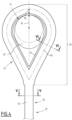
Figure 4 is a face view of the eye shown inFigures 2 and3 , and -
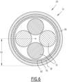
Figures 5 and6 are cross-sectional views of the rope shown infigures 2 to 4 , performed under the eye (Figure 5 ) and in the eye (Figure 6 ) perpendicularly to an extension line of the rope and the eye. - With reference to
Figures 1 to 3 , an offshorepower production installation 10 according to the invention will be described. - The
installation 10 comprises aplatform 12 adapted for floating on a body ofwater 14, and comprising ahull 16 and at least oneconnector 18 having aconnection member 20 forming a hook protruding from the hull. Theinstallation 10 comprises awind turbine 22 mounted on theplatform 12. - The
installation 10 comprises at least onemooring line 24 adapted for connecting theplatform 12 and aseabed 26, and comprising arope 28 having anupper portion 30 forming aneye 32, the rope being mobile with respect to thehull 16 between a connected position (Figures 1 to 3 ), in which theeye 32 surrounds theconnection member 20 and themooring line 24 is intended to apply a traction T on theconnection member 20, and a disconnected position (not shown, but derivable from the connected position by sliding theeye 32 away from the connector 18). - As a variant (not shown), the
installation 10 comprises a plurality of floating platforms, with a plurality of wind turbines respectively fixed on the platforms. - Advantageously, the
installation 10 has several other mooring lines (not shown), which are for example structurally analogous to themooring line 24. As variants, the other mooring lines are of different, and of known types. The mooring lines form a mooring system. - In case there are several mooring lines analogous to the
mooring line 24, the installation advantageously comprises several corresponding connectors, for example structurally analogous to theconnector 18 and distributed around thehull 16. - The body of
water 14 is for example an ocean, a sea or a lake. - The
wind turbine 22 is adapted for producing said power. - The
hull 16 is for example a metal structure defining aninterior volume 34, andexterior volume 36 occupied by the body ofwater 14 or theatmosphere 38. - As best seen in
Figures 2 and3 , apart from the above mentionedconnection member 20, theconnector 18 for example comprises a plurality ofreinforcement members 40. - Advantageously, the
connector 18 comprises ananti-uplift system 42 mobile with respect to thehull 16 between a closed position (Figures 1 to 3 ), and an open position (not shown, but which can be deduced from the closed position based on the below explanations). - The
connector 18 is advantageously below asurface 44 of the body ofwater 14. - In a particular embodiment (not shown), the
connector 18 does not have thereinforcement members 40, for example in case theconnection member 20 is strong enough to resist the traction T applied by themooring line 24. - In another particular embodiment (not shown), the
connector 18 does not include theanti-uplift system 42, for example in case the hook has a more curved shape than in the example, that would naturally prevent therope 28 from switching from to connected position to the disconnected position in extreme weather conditions. According to another case, for example thanks to a particular dynamic behavior of themooring line 24, the risk of an uplift of theeye 32 could be so low, or non-existent, that theanti-uplift system 42 is not useful. - The
connection member 20 is advantageously tubular. Theconnection member 20 advantageously extends along acurved line 46, allowing smooth movements of theeye 32 with respect to theconnection member 20 in the connected position. - As a variant (not shown), the
connection member 20 may follow a different line, for example showing an angle. - For example, along said
line 46, theconnection member 20 has aproximal portion 48 with respect to thehull 16, amedian portion 50 intended to bear themooring line 24, and adistal portion 52 intended to point upwards (theline 46 within thedistal portion 52 points upwards when theplatform 12 is in an average floating position). - For example, the
connection member 20, advantageously in themedian portion 50, defines a contact surface S1 (figure 4 ) intended to be in contact with themooring line 24 in the connected position, the contact surface S1 having a minimum radius of curvature R1. - The notion of minimum radius of curvature at a point of a surface is known to the skilled person, and is usually defined as the radius of the smallest osculating circle at said point.
- For example, starting from the
hull 16, theconnection member 20 gets slimmer along theline 46. - The
connection member 20 is for example welded to thehull 16. - In a particular embodiment, the
connection member 20 is made of steel and fitted with aspecial coating 54 adapted for limiting friction and thus wear of themooring line 24. - The
coating 54 is for example in polytetrafluoroethylene or ceramic. - The
line 46 advantageously extends in a vertical plane P (figure 3 ) when theplatform 12 is in said average floating position. For example, theline 46 approximately forms a quarter of an ellipse or of a circle. - In the closed position, the
anti-uplift system 42 is fixed to thehull 16 and to thedistal portion 52 of theconnection member 20, and theeye 32 is trapped in aloop 56 formed by theconnection member 20, theanti-uplift system 42, and in the example by thehull 16. The closed position is adapted for preventing therope 28 from switching from the connected position to the disconnected position. - As a variant (not shown), the
loop 56 is for example formed only by theconnection member 20 and theanti-uplift system 42. - In the open position of the
anti-uplift system 42, therope 28 remains movable from the disconnected position to the connected position. - For example, the
anti-uplift system 42 comprises abar 58. - Advantageously, the
anti-uplift system 42 is mounted on thehull 16 movable between the closed position and the open position, and has adistal extremity 60 adapted for being locked on thedistal portion 52 of theconnection member 20 in the closed position. For example, thebar 58 is adapted for pivoting with respect to thehull 16 around an axis R. - The axis R is for example vertical when the
platform 12 is in the average floating position. - As a variant (not shown), the axis R is horizontal when the
platform 12 is in the average floating position. In other words, thebar 58 is intended to pivot vertically, instead of horizontally. - The
reinforcement members 40, or gussets, are adapted for reinforcing the connection of theconnection member 20 to thehull 16. - Advantageously, the
reinforcement members 40 respectively includeplates 62 fixed to thehull 16 and to theconnection member 20, theplates 62 for example extending radially from theconnection member 20 downwards. - The
mooring line 24 has alower part 64 and anupper part 68 when connected to theplatform 12 and to theseabed 26, therope 28 being only in theupper part 68 in the example. - As a variant (not shown), the
rope 28 also extends in thelower part 64 until an anchoringstructure 70. - The
lower part 64 for example comprises achain 72. - In the example, the
mooring line 24 further comprises a metal thimble 74 (Figure 4 ), theeye 32 surrounding the thimble around theconnection member 20 in the connected position, and the thimble being intended to be in contact with the connection member in the connected position. - The
thimble 74 advantageously protects theeye 32 from friction. - As a variant, there is no thimble. The
eye 32 is in direct contact with theconnection member 20. - The
rope 28 includes a material having a Young's modulus larger than 50 GPa, the material being a polymer material or carbon fivers. The material is advantageously resistant to abrasion. - For example, the polymer material comprises, or in a particular embodiment is, high modulus polyethylene (HMPE or UHMWPE) or aromatic polyamide.
- The polymer material may comprise reinforcing carbon fibers.
- The
rope 28 for examples comprises a plurality ofsubropes 76 containing said material, and advantageously made of said material. - The
rope 28 advantageously comprises asand filter 78 comprising aribbon 80 helically rolled around said plurality ofsubropes 76 considered a whole, while overlapping, thesand filter 78 being adapted for preventing sand (not shown) and marine growth from reaching the subropes from outside the rope. - The
rope 28 for example comprises abraided cover 82 located on thesand filter 78. - In a particular embodiment (not shown), the
braided cover 82 is the most external layer of thewhole rope 28. - In another particular embodiment, the
braided cover 82 is the most external layer of therope 28 except in theupper portion 30 forming theeye 32. - For example, the
braided cover 82 comprises HMPE or aromatic polyamide, and is made of HMPE or aromatic polyamide in a particular embodiment. - For example, the
rope 28 comprises apolyurethane coating 86 at least within saideye 32. - For example, the
ribbon 80 forms sixlayers 88 on thesubropes 76 due to overlapping. - For example, the
rope 28 has a radius R2, in particular within the eye (32). - Advantageously, the minimum radius of curvature R1 divided by the radius R2 defines a ratio R1/R2 greater than or equal to 2.0, preferably 2.5.
- Advantageously the ratio R1/R2 is smaller than or equal to 4.0, preferably 3.5.
- For example, the ratio R1/R2 is approximately 3.0.
- In case the contact surface S1 is reduced to a line of contact, then R1 is the minimum radius of curvature of that line.
- When the
installation 10 is in operation, therope 28 is in the connected position. Advantageously, theanti-uplift system 42 is in the closed position and prevents therope 28 from switching from the connected position to the disconnected position, in case of storm conditions (should uplift occurs). - For switching from the connected position to the connected position, or vice-versa, the
anti-uplift system 42 is put in the open position. - A method of building the
installation 10 will now be briefly described. - The method comprises providing the
platform 12, thewind turbine 22 and themooring line 24, moving therope 28 from the disconnected position to the connected position, and anchoring themooring line 24 to theseabed 26. - The method also comprises tensioning the
mooring line 24, the mooring line applying the traction T on theconnection member 20. - Advantageously, the
rope 28 is moved from the disconnected position to the connected position by connecting theupper part 68 to the connectingmember 20, thelower part 64 and theupper part 68 being disconnected from one another. This is advantageously performed before bringing theplatform 12 to its operation location on the body ofwater 14, for example when theplatform 12 is on a quay (not shown). Theupper part 68 may be deployed once theplatform 12 is at its operation location. By doing so, theeye 32 does not have to be connected to theconnection member 20 while the connection member is under water. - Advantageously, the
lower part 64 of themooring line 24 is anchored to theseabed 26 while thelower part 64 and theupper part 68 are still disconnected from one another. - The
lower part 64 and theupper part 68 are advantageously connected to each other after theplatform 12 is brought to its operation location. - Tensioning allows reaching a nominal tension of the
mooring line 24. - Thanks to the above features, the
installation 10 does not include an expensive connector, at least for connecting themooring line 24 to theplatform 12, and advantageously for all of its mooring lines (not shown). Investment costs and the LCOE (levelized cost of energy) are thus reduced. - For connecting the
rope 28 to theconnector 18, theupper portion 30 is advantageously hooked directly to theconnection member 20. - As opposed to prior art, the
connection member 20 is fixed with respect to thehull 16, and does not rotate along two axes of rotation (no mechanical component / no bushing), which would limit the bending moment in the mooring line. Instead, thanks to HMPE or aromatic polyamide, therope 28 has a high resistance and is able to withstand wear and bending induced by motions of theplatform 12. - Advantageously, the
anti-uplift system 42 ensures that no uplift of therope 28 occurs in the connected position.
Claims (15)
- An offshore power production installation (10) comprising:- at least one platform (12) adapted for floating on body of water (14), and comprising a hull (16), and at least one connector (18) having a connection member (20) forming a hook protruding from the hull (16),- a wind turbine (22) mounted on the platform (12), and- at least one mooring line (24) adapted for connecting the platform (12) and a seabed (26), and comprising a rope (28) having an upper portion (30) forming an eye (32), the rope (28) including a material having a Young's modulus larger than 50 GPa, the material being a polymer material or carbon fibers, and the rope (28) being mobile with respect to the hull (16) between:- a disconnected position in which the eye (32) is away from the connector (18), and- a connected position in which the eye (32) surrounds the connection member (20) and the mooring line (24) is intended to apply a traction (T) on the connection member (20).
- The installation (10) according to claim 1, wherein the connection member (20) is tubular.
- The installation (10) according to claim 1 or 2, wherein the connector (18) comprises an anti-uplift system (42) mobile with respect to the hull (16) between:- a closed position, in which the anti-uplift system (42) is fixed to the hull (16) and to a distal portion (52) of the connection member (20) with respect to the hull (16), and in which the eye (32) is trapped in a loop (56) formed at least by the connection member (20) and the anti-uplift system (42), and in which the rope (28) is prevented from switching from the connected position to the disconnected position, and- an open position, in which the rope (28) is movable from the disconnected position to the connected position.
- The installation (10) according to claim 3, wherein the anti-uplift system (42) is mounted on the hull (16) movable between the closed position and the open position, and has a distal extremity (60) adapted for being locked on the distal portion (52) of the connection member (20) in the closed position.
- The installation (10) according to any one of claims 1 to 4, wherein the connection member (20) extends along a curved line (46), the distal portion (52) being intended to point upwards.
- The installation (10) according to claim 5, wherein:- the connection member (20) defines a contact surface (S1) intended to be in contact with the mooring line (24) in the connected position, the contact surface (S1) having a minimum radius of curvature (R1),- the rope (28) has a radius (R2), and- the minimum radius of curvature (R1) divided by the radius (R2) defines a ratio (R1/R2) greater than or equal to 2.0.
- The installation (10) according to any one of claims 1 to 6, wherein the connector (18) comprises a plurality of reinforcement members (40) respectively including plates (62) fixed to the hull (16) and to the connection member (20), the plates (62) extending radially from the connection member (20) downwards, the reinforcement members (40) being adapted for reinforcing connection of the connection member (20) to the hull (16).
- The installation (10) according to any one of claims 1 to 7, wherein the mooring line (24) has a lower part (64) and an upper part (68) when connected to the platform (12) and to the seabed (26), the rope (28) being only in the upper part (68) of the mooring line (24).
- The installation (10) according to any one of claims 1 to 8, wherein the rope (28) comprises a plurality of subropes (76) containing said material.
- The installation (10) according to any one of claims 1 to 9, wherein the connection member (20) comprises a coating (54) adapted for reducing abrasion of the mooring line (24).
- The installation (10) according to claim 10, wherein the coating (54) comprises polytetrafluoroethylene or ceramic.
- The installation (10) according to any one of claims 1 to 11, wherein the rope (28) comprises a polyurethane coating (86) at least within said eye (32).
- The installation (10) according to any one of claims 1 to 12, wherein the mooring line (24) comprises a metal thimble (74), the eye (32) surrounding the thimble (74) around the connection member (20) in the connected position, and the thimble (74) being intended to be in contact with the connection member (20) in the connected position.
- A method of building an installation (10) as described by any one of claims 1 to 13, comprising the following steps:- providing the platform (12), the wind turbine (22) and the mooring line (24),- moving the rope (28) from the disconnected position to the connected position,- anchoring the mooring line (24) to the seabed (26), and- tensioning the mooring line (24), the mooring line (24) applying said traction (T) on the connection member (20).
- The method according to claim 14, wherein:- the mooring line (24) comprises an upper part (68) including at least part of the rope (28) and intended to be connected to the connection member (20), and a lower part (64) intended to be anchored to the seabed (26), and- moving the rope (28) from the disconnected position to the connected position includes connecting the upper part (68) to the connecting member (20) prior to bringing the platform (12) to an operation location on the body of water (14), the lower part (64) and the upper part (68) being disconnected from one another,the method comprising:- connecting the lower part (64) to the upper part (68) after bringing the platform (12) at the operation location, and- reaching a nominal tension of the mooring line (24).
Priority Applications (2)
| Application Number | Priority Date | Filing Date | Title |
|---|---|---|---|
| EP23305839.5A EP4467441A1 (en) | 2023-05-26 | 2023-05-26 | An offshore power production installation comprising a floating platform with a connection member forming a hook for connection to a mooring line including a synthetic rope |
| PCT/EP2024/064292 WO2024245910A1 (en) | 2023-05-26 | 2024-05-23 | An offshore power production installation comprising a floating platform with a connection member forming a hook for connection to a mooring line including a synthetic rope |
Applications Claiming Priority (1)
| Application Number | Priority Date | Filing Date | Title |
|---|---|---|---|
| EP23305839.5A EP4467441A1 (en) | 2023-05-26 | 2023-05-26 | An offshore power production installation comprising a floating platform with a connection member forming a hook for connection to a mooring line including a synthetic rope |
Publications (1)
| Publication Number | Publication Date |
|---|---|
| EP4467441A1 true EP4467441A1 (en) | 2024-11-27 |
Family
ID=86776410
Family Applications (1)
| Application Number | Title | Priority Date | Filing Date |
|---|---|---|---|
| EP23305839.5A Withdrawn EP4467441A1 (en) | 2023-05-26 | 2023-05-26 | An offshore power production installation comprising a floating platform with a connection member forming a hook for connection to a mooring line including a synthetic rope |
Country Status (2)
| Country | Link |
|---|---|
| EP (1) | EP4467441A1 (en) |
| WO (1) | WO2024245910A1 (en) |
Citations (5)
| Publication number | Priority date | Publication date | Assignee | Title |
|---|---|---|---|---|
| EP2927489A1 (en) * | 2012-11-30 | 2015-10-07 | MHI Vestas Offshore Wind A/S | Floating-body type wind power generation device and method for transporting components of same |
| WO2016114671A1 (en) * | 2015-01-15 | 2016-07-21 | Calorflex As | A mooring member |
| WO2019007975A2 (en) * | 2017-07-03 | 2019-01-10 | Subsea 7 Norway As | Offloading hydrocarbons from subsea fields |
| GB2587050A (en) * | 2020-05-22 | 2021-03-17 | Smart Energy Solutions International Ltd | Disconnectable mooring system for offshore floating semi-submersible |
| EP3943747A1 (en) * | 2020-07-24 | 2022-01-26 | Siemens Gamesa Renewable Energy A/S | Monitoring of mooring lines of a floating wind turbine |
-
2023
- 2023-05-26 EP EP23305839.5A patent/EP4467441A1/en not_active Withdrawn
-
2024
- 2024-05-23 WO PCT/EP2024/064292 patent/WO2024245910A1/en not_active Ceased
Patent Citations (5)
| Publication number | Priority date | Publication date | Assignee | Title |
|---|---|---|---|---|
| EP2927489A1 (en) * | 2012-11-30 | 2015-10-07 | MHI Vestas Offshore Wind A/S | Floating-body type wind power generation device and method for transporting components of same |
| WO2016114671A1 (en) * | 2015-01-15 | 2016-07-21 | Calorflex As | A mooring member |
| WO2019007975A2 (en) * | 2017-07-03 | 2019-01-10 | Subsea 7 Norway As | Offloading hydrocarbons from subsea fields |
| GB2587050A (en) * | 2020-05-22 | 2021-03-17 | Smart Energy Solutions International Ltd | Disconnectable mooring system for offshore floating semi-submersible |
| EP3943747A1 (en) * | 2020-07-24 | 2022-01-26 | Siemens Gamesa Renewable Energy A/S | Monitoring of mooring lines of a floating wind turbine |
Also Published As
| Publication number | Publication date |
|---|---|
| WO2024245910A1 (en) | 2024-12-05 |
Similar Documents
| Publication | Publication Date | Title |
|---|---|---|
| US5339760A (en) | Apparatus for securing a vessel to a submersible mooring buoy | |
| AU2009203199B2 (en) | Mooring chain connector assembly for a floating device | |
| KR102450895B1 (en) | Turbine systems and mooring systems | |
| EP2110307B1 (en) | Mooring system | |
| US5651708A (en) | Arrangement for buoy loading | |
| KR102958322B1 (en) | Ship mooring system and method using the same | |
| EP4393808A1 (en) | Mooring system for floating structure and installation method | |
| WO2022013145A1 (en) | A mooring system for a plurality of floating units | |
| WO2014178721A2 (en) | Subsea remotely operated chain tensioning and slacking system | |
| US20160368572A1 (en) | Floating wind turbine | |
| US8100077B2 (en) | Mooring system | |
| CN114829244A (en) | Mooring support structure, system for mooring a vessel and method of use thereof | |
| WO2022164371A1 (en) | Mooring system | |
| WO2024245910A1 (en) | An offshore power production installation comprising a floating platform with a connection member forming a hook for connection to a mooring line including a synthetic rope | |
| JP7696934B2 (en) | Floating Wind Turbine | |
| NO348512B1 (en) | System for connecting power or fluid lines to a floating energy converter device | |
| WO2025219732A1 (en) | Methods and systems for offshore mooring operations | |
| WO2024151204A1 (en) | Mooring link | |
| US4669412A (en) | Boom for single point mooring system | |
| US4359959A (en) | Device for mooring a floating installation to an anchored offshore installation | |
| WO2016092311A1 (en) | Composite component deployment configurations | |
| SE546272C2 (en) | Mooring unit for mooring a floating object | |
| JP7809641B2 (en) | Mooring systems and methods | |
| SE546271C2 (en) | Mooring unit for mooring a floating object | |
| WO2026017251A1 (en) | Tension leg platform assembly, mooring assembly and connector assembly |
Legal Events
| Date | Code | Title | Description |
|---|---|---|---|
| PUAI | Public reference made under article 153(3) epc to a published international application that has entered the european phase |
Free format text: ORIGINAL CODE: 0009012 |
|
| STAA | Information on the status of an ep patent application or granted ep patent |
Free format text: STATUS: THE APPLICATION HAS BEEN PUBLISHED |
|
| AK | Designated contracting states |
Kind code of ref document: A1 Designated state(s): AL AT BE BG CH CY CZ DE DK EE ES FI FR GB GR HR HU IE IS IT LI LT LU LV MC ME MK MT NL NO PL PT RO RS SE SI SK SM TR |
|
| STAA | Information on the status of an ep patent application or granted ep patent |
Free format text: STATUS: THE APPLICATION IS DEEMED TO BE WITHDRAWN |
|
| 18D | Application deemed to be withdrawn |
Effective date: 20250528 |