EP4467339A1 - Compound curve component lamination method and product - Google Patents
Compound curve component lamination method and product Download PDFInfo
- Publication number
- EP4467339A1 EP4467339A1 EP24177780.4A EP24177780A EP4467339A1 EP 4467339 A1 EP4467339 A1 EP 4467339A1 EP 24177780 A EP24177780 A EP 24177780A EP 4467339 A1 EP4467339 A1 EP 4467339A1
- Authority
- EP
- European Patent Office
- Prior art keywords
- substrate
- compound curve
- chamber
- oca
- oca sheet
- Prior art date
- Legal status (The legal status is an assumption and is not a legal conclusion. Google has not performed a legal analysis and makes no representation as to the accuracy of the status listed.)
- Granted
Links
Images




Classifications
-
- B—PERFORMING OPERATIONS; TRANSPORTING
- B32—LAYERED PRODUCTS
- B32B—LAYERED PRODUCTS, i.e. PRODUCTS BUILT-UP OF STRATA OF FLAT OR NON-FLAT, e.g. CELLULAR OR HONEYCOMB, FORM
- B32B37/00—Methods or apparatus for laminating, e.g. by curing or by ultrasonic bonding
- B32B37/12—Methods or apparatus for laminating, e.g. by curing or by ultrasonic bonding characterised by using adhesives
-
- B—PERFORMING OPERATIONS; TRANSPORTING
- B32—LAYERED PRODUCTS
- B32B—LAYERED PRODUCTS, i.e. PRODUCTS BUILT-UP OF STRATA OF FLAT OR NON-FLAT, e.g. CELLULAR OR HONEYCOMB, FORM
- B32B38/00—Ancillary operations in connection with laminating processes
- B32B38/18—Handling of layers or the laminate
- B32B38/1866—Handling of layers or the laminate conforming the layers or laminate to a convex or concave profile
-
- B—PERFORMING OPERATIONS; TRANSPORTING
- B32—LAYERED PRODUCTS
- B32B—LAYERED PRODUCTS, i.e. PRODUCTS BUILT-UP OF STRATA OF FLAT OR NON-FLAT, e.g. CELLULAR OR HONEYCOMB, FORM
- B32B1/00—Layered products having a non-planar shape
-
- B—PERFORMING OPERATIONS; TRANSPORTING
- B32—LAYERED PRODUCTS
- B32B—LAYERED PRODUCTS, i.e. PRODUCTS BUILT-UP OF STRATA OF FLAT OR NON-FLAT, e.g. CELLULAR OR HONEYCOMB, FORM
- B32B17/00—Layered products essentially comprising sheet glass, or glass, slag, or like fibres
- B32B17/06—Layered products essentially comprising sheet glass, or glass, slag, or like fibres comprising glass as the main or only constituent of a layer, next to another layer of a specific material
- B32B17/10—Layered products essentially comprising sheet glass, or glass, slag, or like fibres comprising glass as the main or only constituent of a layer, next to another layer of a specific material of synthetic resin
- B32B17/10005—Layered products essentially comprising sheet glass, or glass, slag, or like fibres comprising glass as the main or only constituent of a layer, next to another layer of a specific material of synthetic resin laminated safety glass or glazing
-
- B—PERFORMING OPERATIONS; TRANSPORTING
- B32—LAYERED PRODUCTS
- B32B—LAYERED PRODUCTS, i.e. PRODUCTS BUILT-UP OF STRATA OF FLAT OR NON-FLAT, e.g. CELLULAR OR HONEYCOMB, FORM
- B32B17/00—Layered products essentially comprising sheet glass, or glass, slag, or like fibres
- B32B17/06—Layered products essentially comprising sheet glass, or glass, slag, or like fibres comprising glass as the main or only constituent of a layer, next to another layer of a specific material
- B32B17/10—Layered products essentially comprising sheet glass, or glass, slag, or like fibres comprising glass as the main or only constituent of a layer, next to another layer of a specific material of synthetic resin
- B32B17/10005—Layered products essentially comprising sheet glass, or glass, slag, or like fibres comprising glass as the main or only constituent of a layer, next to another layer of a specific material of synthetic resin laminated safety glass or glazing
- B32B17/10807—Making laminated safety glass or glazing; Apparatus therefor
- B32B17/10816—Making laminated safety glass or glazing; Apparatus therefor by pressing
-
- B—PERFORMING OPERATIONS; TRANSPORTING
- B32—LAYERED PRODUCTS
- B32B—LAYERED PRODUCTS, i.e. PRODUCTS BUILT-UP OF STRATA OF FLAT OR NON-FLAT, e.g. CELLULAR OR HONEYCOMB, FORM
- B32B17/00—Layered products essentially comprising sheet glass, or glass, slag, or like fibres
- B32B17/06—Layered products essentially comprising sheet glass, or glass, slag, or like fibres comprising glass as the main or only constituent of a layer, next to another layer of a specific material
- B32B17/10—Layered products essentially comprising sheet glass, or glass, slag, or like fibres comprising glass as the main or only constituent of a layer, next to another layer of a specific material of synthetic resin
- B32B17/10005—Layered products essentially comprising sheet glass, or glass, slag, or like fibres comprising glass as the main or only constituent of a layer, next to another layer of a specific material of synthetic resin laminated safety glass or glazing
- B32B17/10807—Making laminated safety glass or glazing; Apparatus therefor
- B32B17/10816—Making laminated safety glass or glazing; Apparatus therefor by pressing
- B32B17/10825—Isostatic pressing, i.e. using non rigid pressure-exerting members against rigid parts
- B32B17/10834—Isostatic pressing, i.e. using non rigid pressure-exerting members against rigid parts using a fluid
- B32B17/10844—Isostatic pressing, i.e. using non rigid pressure-exerting members against rigid parts using a fluid using a membrane between the layered product and the fluid
-
- B—PERFORMING OPERATIONS; TRANSPORTING
- B32—LAYERED PRODUCTS
- B32B—LAYERED PRODUCTS, i.e. PRODUCTS BUILT-UP OF STRATA OF FLAT OR NON-FLAT, e.g. CELLULAR OR HONEYCOMB, FORM
- B32B17/00—Layered products essentially comprising sheet glass, or glass, slag, or like fibres
- B32B17/06—Layered products essentially comprising sheet glass, or glass, slag, or like fibres comprising glass as the main or only constituent of a layer, next to another layer of a specific material
- B32B17/10—Layered products essentially comprising sheet glass, or glass, slag, or like fibres comprising glass as the main or only constituent of a layer, next to another layer of a specific material of synthetic resin
- B32B17/10005—Layered products essentially comprising sheet glass, or glass, slag, or like fibres comprising glass as the main or only constituent of a layer, next to another layer of a specific material of synthetic resin laminated safety glass or glazing
- B32B17/10807—Making laminated safety glass or glazing; Apparatus therefor
- B32B17/10899—Making laminated safety glass or glazing; Apparatus therefor by introducing interlayers of synthetic resin
- B32B17/10935—Making laminated safety glass or glazing; Apparatus therefor by introducing interlayers of synthetic resin as a preformed layer, e.g. formed by extrusion
-
- B—PERFORMING OPERATIONS; TRANSPORTING
- B32—LAYERED PRODUCTS
- B32B—LAYERED PRODUCTS, i.e. PRODUCTS BUILT-UP OF STRATA OF FLAT OR NON-FLAT, e.g. CELLULAR OR HONEYCOMB, FORM
- B32B37/00—Methods or apparatus for laminating, e.g. by curing or by ultrasonic bonding
- B32B37/10—Methods or apparatus for laminating, e.g. by curing or by ultrasonic bonding characterised by the pressing technique, e.g. using action of vacuum or fluid pressure
- B32B37/1009—Methods or apparatus for laminating, e.g. by curing or by ultrasonic bonding characterised by the pressing technique, e.g. using action of vacuum or fluid pressure using vacuum and fluid pressure
-
- B—PERFORMING OPERATIONS; TRANSPORTING
- B32—LAYERED PRODUCTS
- B32B—LAYERED PRODUCTS, i.e. PRODUCTS BUILT-UP OF STRATA OF FLAT OR NON-FLAT, e.g. CELLULAR OR HONEYCOMB, FORM
- B32B37/00—Methods or apparatus for laminating, e.g. by curing or by ultrasonic bonding
- B32B37/12—Methods or apparatus for laminating, e.g. by curing or by ultrasonic bonding characterised by using adhesives
- B32B37/1284—Application of adhesive
-
- B—PERFORMING OPERATIONS; TRANSPORTING
- B32—LAYERED PRODUCTS
- B32B—LAYERED PRODUCTS, i.e. PRODUCTS BUILT-UP OF STRATA OF FLAT OR NON-FLAT, e.g. CELLULAR OR HONEYCOMB, FORM
- B32B38/00—Ancillary operations in connection with laminating processes
- B32B38/0004—Cutting, tearing or severing, e.g. bursting; Cutter details
-
- B—PERFORMING OPERATIONS; TRANSPORTING
- B32—LAYERED PRODUCTS
- B32B—LAYERED PRODUCTS, i.e. PRODUCTS BUILT-UP OF STRATA OF FLAT OR NON-FLAT, e.g. CELLULAR OR HONEYCOMB, FORM
- B32B7/00—Layered products characterised by the relation between layers; Layered products characterised by the relative orientation of features between layers, or by the relative values of a measurable parameter between layers, i.e. products comprising layers having different physical, chemical or physicochemical properties; Layered products characterised by the interconnection of layers
- B32B7/04—Interconnection of layers
- B32B7/12—Interconnection of layers using interposed adhesives or interposed materials with bonding properties
-
- B—PERFORMING OPERATIONS; TRANSPORTING
- B32—LAYERED PRODUCTS
- B32B—LAYERED PRODUCTS, i.e. PRODUCTS BUILT-UP OF STRATA OF FLAT OR NON-FLAT, e.g. CELLULAR OR HONEYCOMB, FORM
- B32B2250/00—Layers arrangement
- B32B2250/03—3 layers
-
- B—PERFORMING OPERATIONS; TRANSPORTING
- B32—LAYERED PRODUCTS
- B32B—LAYERED PRODUCTS, i.e. PRODUCTS BUILT-UP OF STRATA OF FLAT OR NON-FLAT, e.g. CELLULAR OR HONEYCOMB, FORM
- B32B2250/00—Layers arrangement
- B32B2250/40—Symmetrical or sandwich layers, e.g. ABA, ABCBA, ABCCBA
-
- B—PERFORMING OPERATIONS; TRANSPORTING
- B32—LAYERED PRODUCTS
- B32B—LAYERED PRODUCTS, i.e. PRODUCTS BUILT-UP OF STRATA OF FLAT OR NON-FLAT, e.g. CELLULAR OR HONEYCOMB, FORM
- B32B2307/00—Properties of the layers or laminate
- B32B2307/40—Properties of the layers or laminate having particular optical properties
- B32B2307/412—Transparent
-
- B—PERFORMING OPERATIONS; TRANSPORTING
- B32—LAYERED PRODUCTS
- B32B—LAYERED PRODUCTS, i.e. PRODUCTS BUILT-UP OF STRATA OF FLAT OR NON-FLAT, e.g. CELLULAR OR HONEYCOMB, FORM
- B32B2309/00—Parameters for the laminating or treatment process; Apparatus details
- B32B2309/60—In a particular environment
- B32B2309/68—Vacuum
-
- B—PERFORMING OPERATIONS; TRANSPORTING
- B32—LAYERED PRODUCTS
- B32B—LAYERED PRODUCTS, i.e. PRODUCTS BUILT-UP OF STRATA OF FLAT OR NON-FLAT, e.g. CELLULAR OR HONEYCOMB, FORM
- B32B2457/00—Electrical equipment
- B32B2457/20—Displays, e.g. liquid crystal displays, plasma displays
-
- B—PERFORMING OPERATIONS; TRANSPORTING
- B32—LAYERED PRODUCTS
- B32B—LAYERED PRODUCTS, i.e. PRODUCTS BUILT-UP OF STRATA OF FLAT OR NON-FLAT, e.g. CELLULAR OR HONEYCOMB, FORM
- B32B2605/00—Vehicles
- B32B2605/006—Transparent parts other than made from inorganic glass, e.g. polycarbonate glazings
-
- B—PERFORMING OPERATIONS; TRANSPORTING
- B32—LAYERED PRODUCTS
- B32B—LAYERED PRODUCTS, i.e. PRODUCTS BUILT-UP OF STRATA OF FLAT OR NON-FLAT, e.g. CELLULAR OR HONEYCOMB, FORM
- B32B2605/00—Vehicles
- B32B2605/08—Cars
-
- B—PERFORMING OPERATIONS; TRANSPORTING
- B32—LAYERED PRODUCTS
- B32B—LAYERED PRODUCTS, i.e. PRODUCTS BUILT-UP OF STRATA OF FLAT OR NON-FLAT, e.g. CELLULAR OR HONEYCOMB, FORM
- B32B2605/00—Vehicles
- B32B2605/18—Aircraft
Definitions
- the present disclosure relates generally to optical bonding technology, and more particularly, to methods of direct dry film (DDF) laminating compound curve substrates and compound curve products produced by such methods.
- DDF direct dry film
- Optical bonding is the process of bonding two or more optical components together using a clear optical index matched adhesive.
- components to be optically bonded include, but are not limited to, anti-reflective glass, protective glass, touch screens, ITO heaters, EMI shields, and additional displays.
- Components may be bonded to the front, rear, or both sides of a display or to another optical component.
- Optical bonding may also be used to produce aircraft canopies, automotive windshields, and other safety glass applications.
- Industries benefiting from optical bonding include, but are not limited to, military, avionics, ground vehicles, and automotive displays requiring very high optical and environmental performances.
- Optical bonding technologies include dry optical bonding and liquid optical bonding. In some cases, dry optical bonding is preferred considering scalability, low environmental impact, dimensional superiority, and better performance. While dry optical bonding is ideal for planar and single axis curved substrates via cold forming and optically clear adhesive (OCA) application, current processes for applying dry adhesives to compound curve substrates is not possible.
- OCA optically clear adhesive
- embodiments of the inventive concepts disclosed herein are directed to a method of direct dry film (DDF) laminating a compound curve substrate.
- the method includes providing a chamber including a bladder, positioning a frame in the chamber, and positioning a compound curve substrate in an interior space formed within the frame.
- the method continues by suspending, via the frame, an optically clear adhesive (OCA) sheet over the compound curve substrate, the OCA sheet including a top liner.
- OCA optically clear adhesive
- the method continues with structurally altering the top liner at one or more locations corresponding to curvature of the compound curve substrate, evacuating the chamber to induce a vacuum, deploying the bladder to bring the OCA sheet into conformed contact with the compound curve substrate, retracting the bladder, and venting the chamber.
- the method continues with bonding a matched second substrate to the applied, bonded and conformed OCA sheet.
- the OCA sheet further includes a bottom liner
- the method further includes removing the bottom liner before evacuating the chamber.
- structurally altering the top liner includes cutting the top liner.
- the method further includes positioning the matched second substrate in the chamber, evacuating the chamber to induce a vacuum, deploying the bladder to bring the matched compound curve second substrate into conformed contact with the OCA sheet, retracting the bladder, and venting the chamber.
- the second substrate is a flexible film or a rigid compound curve substrate having a curvature profile matching a curvature profile of the first compound curve substrate.
- the method further includes, prior to bonding the second matched substrate to the OCA sheet, trimming the OCA sheet to the substrate edge or insert dimension, and removing the top liner.
- the OCA sheet is maintained in conformed contact with the compound curve substrate for a predetermined time period.
- the method further includes heating at least one of the chamber, the OCA sheet, and the compound curve substrate.
- the OCA sheet is coupled to the frame by a plurality of elastic members.
- the method continues by structurally altering the top liner at one or more locations corresponding to curvature of the compound curve substrate, evacuating the chamber to induce a vacuum, deploying the bladder to bring the OCA sheet into conformed contact with the compound curve substrate, retracting the bladder, and venting the chamber.
- the method continues by bonding the second substrate to the applied, bonded, and conformed OCA sheet.
- inventive concepts are not limited in their application to the details of construction and the arrangement of the components or steps or methodologies set forth in the following description or illustrated in the drawings.
- inventive concepts disclosed herein may be practiced without these specific details.
- well-known features may not be described in detail to avoid unnecessarily complicating the instant disclosure.
- inventive concepts disclosed herein are capable of other embodiments or of being practiced or carried out in various ways. Also, it is to be understood that the phraseology and terminology employed herein is for the purpose of description and should not be regarded as limiting.
- a letter following a reference numeral is intended to reference an embodiment of the feature or element that may be similar, but not necessarily identical, to a previously described element or feature bearing the same reference numeral (e.g., 1, 1a, 1b).
- reference numeral e.g. 1, 1a, 1b
- Such shorthand notations are used for purposes of convenience only, and should not be construed to limit the inventive concepts disclosed herein in any way unless expressly stated to the contrary.
- any reference to “one embodiment” or “some embodiments” means that a particular element, feature, structure, or characteristic described in connection with the embodiment is included in at least one embodiment of the inventive concepts disclosed herein.
- the appearances of the phrase “in some embodiments” in various places in the specification are not necessarily all referring to the same embodiment, and embodiments of the inventive concepts disclosed may include one or more of the features expressly described or inherently present herein, or any combination of sub-combination of two or more such features, along with any other features which may not necessarily be expressly described or inherently present in the instant disclosure.
- the lamination may be a direct dry film (DDF) lamination for applying a flexible adhesive layer to a rigid, compound curve substrate in a bonded stack, i.e., flexible-to-rigid lamination.
- the lamination may be a DDF lamination for applying a rigid compound curve part to a compound curve substrate in a bonded stack, i.e., rigid-to-rigid lamination, wherein the rigid compound curve part and the rigid compound curve substrate having a matching curvature profile.
- the top liner i.e., liner provided on a top side of the OCA sheet facing away from the compound curve substrate
- the top liner is scored, cut or otherwise altered to introduce flexibility into the sheet at strategic locations to allow the sheet to give way while the bottom liner above the part is removed to bring the adhesive into contact with the curved substrate.
- a bladder serves to bring the OCA sheet into intimate contact across the full shape of the curved substrate.
- FIG. 1 is a schematic illustration of a bonded product produced according to a dry bonding lamination method according to the present disclosure.
- the product 100 for example an aircraft canopy, automotive windshield, automotive window, or other safety glass, generally includes a compound curve substrate 102 and a matched (e.g., shaped or optically) second substrate 104 bonded together by an intermediate optically clear adhesive (OCA) sheet 106.
- OCA optically clear adhesive
- each of the first substrate 102 and the second substrate 106 are compound curve substrates, having a matching curvature profile, provided in a bonded stack, i.e., rigid-to-rigid lamination or flexible-to-rigid lamination.
- the product 100 includes additional substrates each bonded by a further intermediate OCA sheet or other adhesive interlayer.
- compound curve means not planar and not single axis curved.
- a compound curve may be normal or reverse curved.
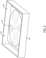
- FIG. 2 is a schematic illustration of tooling suitable for implementing direct dry film (DDF) lamination methods according to the present disclosure.
- a non-planar substrate 200 is positioned in an interior space 202 formed within a frame 204 to be positioned in a DDF chamber.
- the frame 204 is configured to hold an OCA sheet 206 suspended above the non-planar substrate 200.
- the OCA sheet 206 includes a top removable liner structurally altered to induce flexibility in the sheet, and a bottom removable liner to be removed prior to bonding with the substrate 200.
- the OCA sheet 206 is held suspended above the non-planar substrate 200 in order to be positioned to move down by contact from the deploying bladder, after evacuation, during the DDF cycle.
- FIG. 3 is a schematic illustration of alternate tooling for implementing the direct dry film (DDF) lamination method according to the present disclosure.
- a non-planar substrate 200 is positioned in the interior space 202 formed within a frame 204 to be positioned in the DDF chamber.
- the frame 204 is configured to hold an OCA sheet 206 suspended above the non-planar substrate 200.
- the OCA sheet 206 may be attached at its peripheral edges to the frame 204 by a plurality of resiliently flexible members 300, for instance rubber bands, springs, or the like, configured to permit the OCA sheet 206 to move relative to the frame 204 to move down by contact with the deploying bladder, after evacuation, during the DDF cycle.
- FIGS. 4A-D illustrate schematically suitable tooling and sequential steps for DDF laminating a compound curve substrate according to the present disclosure.
- the tooling includes a DDF chamber 400 forming an interior space 402 configured to be atmospherically controlled and evacuated.
- a flexible bladder 404 is provided within the interior space 402 and is configured to be selectively deployed and retracted. In use, the flexible bladder 404 deploys, such as with a controlled pressure differential, to move into contact with the OCA sheet 206 to thereby move the OCA sheet 206 into conformed contact with the underlying compound curve substrate 200.
- the compound curve substrate 200 is positioned within the bounds of the frame 204 and below the OCA sheet 206 suspended from above. In embodiments, the OCA sheet 206 may be dimensioned larger than the compound curve substrate 200 to ensure complete coverage of the bonding surface.
- FIG. 4A shows the positional relationships of the DDF chamber 400, bladder 404, OCA sheet 206, and substrate 200 for bonding, and with the DDF chamber 400 evacuated.
- FIG. 4B shows the bladder 404 deployed, e.g., resiliently deformed, into contact with the OCA sheet 206 thereby moving the OCA sheet 206 into conformed contact with the highly curved bonding surface of the substrate 200. The conformed contact may be maintained for a predetermined time period to ensure adequate bonding with the surface of the substrate 200.
- FIG. 4C shows the bladder 404 retracted out of contact with the now conformed OCA sheet 206 bonded to the substrate 200, and with the DDF chamber 400 vented.
- FIG. 4D shows the substrate 200, having the bonded OCA sheet 206 applied thereto, removed from the DDF chamber for further processing, for instance bonding a flexible film or further compound curved part.
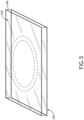
- FIG. 5 shows a structurally altered top liner of an OCA sheet 206 to introduce flexibility to the sheet for facilitating conformity.
- the OCA sheet 206 includes a top and a bottom.
- the "top” refers to the sheet side facing away from the underlying substrate and the "bottom” refers to the sheet side facing the underlying substrate.
- the top is covered with a removable top liner 500 and the bottom is covered with a removable bottom liner 502.
- the top and bottom liners 500, 502 maintain planarity and cleanliness of the OCA sheet 206 prior to bonding.
- the bottom liner 502 is removed prior to evacuating the DDF chamber.
- the top liner 500 remains in place during the DDF process.
- the top liner 500 is shown having been structurally altered depending on the curvature of the substrate.
- Structural altering may include scoring, cutting, combinations of both, and the like for introducing a weakness in the top liner 500 to facilitate stretching the OCA sheet 206 during the conformed contact step.
- Structurally altering the top liner 500 allows the OCA sheet 206 to better conform to the curved shape of the substrate under the force of the deployed bladder.
- the locations of the structural altering may correspond to the curvature of the substrate such that a steeper substrate curve may require greater altering whereas a shallower curve or planar section of the substrate may require lesser altering.
- FIG. 6 illustrates an example implementation of a method 600 of DDF laminating a compound curve substrate.
- operations of disclosed processes e.g., method
- the method may further include any step or operation implied or required by the product embodiments described herein.
- the products described above may also include any additional component or functionality expressed or implied by the method.
- the method occurs in a DDF chamber including an interior space, a deployable bladder positioned in the interior space, and a frame positioned in the interior space beneath the deployable bladder, the frame configured to suspend an OCA sheet.
- the method includes a compound curve substrate in an interior space formed by the frame.
- the method includes suspending an OCA sheet, by the frame, over the to-be-bonded surface of the compound curve substrate.
- the OCA sheet may be altered in place, or previously altered outside of the DDF chamber to introduce a bending weakness in the OCA sheet corresponding to curvature of the underlying compound curve substrate.
- Step 606 With the compound curve substrate and the OCA sheet positioned for bonding, the method continues at Step 606 with evacuating the chamber to induce a vacuum, and Step 608 with deploying the bladder into contact with the OCA sheet to move the OCA sheet into conformed contact with the surface of the compound curve substrate to bond the OCA sheet to the surface.
- the conformed contact may be maintained for a predetermined time period, for instance a matter of seconds or minutes to ensure bonding.
- Step 610 with retracting the bladder and Step 612 with venting the DDF chamber.
- the bonded OCA sheet may be further processed, such as trimmed and the top liner removed.
- a second substrate for instance a flexible film or matching curved substrate, may be bonded to the top of the OCA sheet, for instance within the DDF chamber also via the deployable bladder.
- embodiments of the methods according to the inventive concepts disclosed herein may include one or more of the steps described herein. Further, such steps may be carried out in any desired order and two or more of the steps may be carried out simultaneously with one another. Two or more of the steps disclosed herein may be combined in a single step, and in some embodiments, one or more of the steps may be carried out as two or more sub-steps. Further, other steps or sub-steps may be carried in addition to, or as substitutes to one or more of the steps disclosed herein.
- inventive concepts disclosed herein are well adapted to achieve the objectives and to attain the advantages mentioned herein as well as those inherent in the inventive concepts disclosed herein. While presently preferred embodiments of the inventive concepts disclosed herein have been described for purposes of this disclosure, it will be understood that numerous changes may be made which will readily suggest themselves to those skilled in the art and which are accomplished within the broad scope and coverage of the inventive concepts disclosed and claimed herein.
Landscapes
- Physics & Mathematics (AREA)
- Fluid Mechanics (AREA)
- Engineering & Computer Science (AREA)
- Mechanical Engineering (AREA)
- Lining Or Joining Of Plastics Or The Like (AREA)
Abstract
Description
- The present disclosure relates generally to optical bonding technology, and more particularly, to methods of direct dry film (DDF) laminating compound curve substrates and compound curve products produced by such methods.
- Optical bonding is the process of bonding two or more optical components together using a clear optical index matched adhesive. Examples of components to be optically bonded include, but are not limited to, anti-reflective glass, protective glass, touch screens, ITO heaters, EMI shields, and additional displays. Components may be bonded to the front, rear, or both sides of a display or to another optical component. Optical bonding may also be used to produce aircraft canopies, automotive windshields, and other safety glass applications. Industries benefiting from optical bonding include, but are not limited to, military, avionics, ground vehicles, and automotive displays requiring very high optical and environmental performances.
- Optical bonding technologies include dry optical bonding and liquid optical bonding. In some cases, dry optical bonding is preferred considering scalability, low environmental impact, dimensional superiority, and better performance. While dry optical bonding is ideal for planar and single axis curved substrates via cold forming and optically clear adhesive (OCA) application, current processes for applying dry adhesives to compound curve substrates is not possible.
- Therefore, what is needed is a solution for dry bonding compound curve substrates.
- In one aspect, embodiments of the inventive concepts disclosed herein are directed to a method of direct dry film (DDF) laminating a compound curve substrate. In embodiments, the method includes providing a chamber including a bladder, positioning a frame in the chamber, and positioning a compound curve substrate in an interior space formed within the frame. The method continues by suspending, via the frame, an optically clear adhesive (OCA) sheet over the compound curve substrate, the OCA sheet including a top liner. The method continues with structurally altering the top liner at one or more locations corresponding to curvature of the compound curve substrate, evacuating the chamber to induce a vacuum, deploying the bladder to bring the OCA sheet into conformed contact with the compound curve substrate, retracting the bladder, and venting the chamber. In embodiments, the method continues with bonding a matched second substrate to the applied, bonded and conformed OCA sheet.
- In some embodiments, the OCA sheet further includes a bottom liner, and the method further includes removing the bottom liner before evacuating the chamber.
- In some embodiments, structurally altering the top liner includes scoring the top liner.
- In some embodiments, structurally altering the top liner includes cutting the top liner.
- In some embodiments, the method further includes positioning the matched second substrate in the chamber, evacuating the chamber to induce a vacuum, deploying the bladder to bring the matched compound curve second substrate into conformed contact with the OCA sheet, retracting the bladder, and venting the chamber.
- In some embodiments, the second substrate is a flexible film or a rigid compound curve substrate having a curvature profile matching a curvature profile of the first compound curve substrate.
- In some embodiments, the method further includes, prior to bonding the second matched substrate to the OCA sheet, trimming the OCA sheet to the substrate edge or insert dimension, and removing the top liner.
- In some embodiments, the OCA sheet is maintained in conformed contact with the compound curve substrate for a predetermined time period.
- In some embodiments, the method further includes heating at least one of the chamber, the OCA sheet, and the compound curve substrate.
- In some embodiments, the OCA sheet is coupled to the frame by a plurality of elastic members.
- According to another aspect, the present disclosure provides a laminated compound curve product including a compound curve substrate and a second substrate bonded together by an intermediate optically clear adhesive (OCA) sheet, wherein the laminated compound curve product is produced according to a method of direct dry film (DDF) lamination. In embodiments, the method includes providing a chamber including a bladder, positioning a frame in the chamber, and positioning the compound curve substrate in an interior space within the frame. The method continues with suspending, by the frame, the OCA sheet over the compound curve substrate, the OCA sheet including a top liner. The method continues by structurally altering the top liner at one or more locations corresponding to curvature of the compound curve substrate, evacuating the chamber to induce a vacuum, deploying the bladder to bring the OCA sheet into conformed contact with the compound curve substrate, retracting the bladder, and venting the chamber. In embodiments, the method continues by bonding the second substrate to the applied, bonded, and conformed OCA sheet.
- This summary is provided solely as an introduction to subject matter that is fully described in the following detailed description and drawing figures. This summary should not be considered to describe essential features nor be used to determine the scope of the claims. Moreover, it is to be understood that both the foregoing summary and the following detailed description are explanatory only and are not necessarily restrictive of the subject matter claimed.
- Implementations of the inventive concepts disclosed herein may be better understood when consideration is given to the following detailed description thereof. Such description makes reference to the included drawings, which are not necessarily to scale, and in which some features may be exaggerated and some features may be omitted or may be represented schematically in the interest of clarity. Like reference numerals in the drawings may represent and refer to the same or similar element, feature, or function. In the drawings:
-
FIG. 1 is a schematic cross-section of a compound curve product produced according to a dry bonding lamination method, in accordance with example embodiments of this disclosure; -
FIG. 2 is a schematic illustration of tooling for implementing a direct dry film (DDF) lamination method, in accordance with example embodiments of this disclosure; -
FIG. 3 is a schematic illustration of alternate tooling for implementing a DDF lamination method, in accordance with example embodiments of this disclosure; -
FIGS. 4A-4D illustrate schematically the tooling and sequential steps for DDF laminating a bonded compound curve substrate, in accordance with example embodiments of this disclosure; -
FIG. 5 is a schematic illustration of a structurally altered top liner of an OCA to introduce flexibility, in accordance with example embodiments of this disclosure; and -
FIG. 6 is a flow diagram illustrating an example implementation of a method of DDF laminating compound curve products, in accordance with example embodiments of this disclosure. - Before explaining at least one embodiment of the inventive concepts disclosed herein in detail, it is to be understood that the inventive concepts are not limited in their application to the details of construction and the arrangement of the components or steps or methodologies set forth in the following description or illustrated in the drawings. In the following detailed description of embodiments of the instant inventive concepts, numerous specific details are set forth in order to provide a more thorough understanding of the inventive concepts. However, it will be apparent to one of ordinary skill in the art having the benefit of the instant disclosure that the inventive concepts disclosed herein may be practiced without these specific details. In other instances, well-known features may not be described in detail to avoid unnecessarily complicating the instant disclosure. The inventive concepts disclosed herein are capable of other embodiments or of being practiced or carried out in various ways. Also, it is to be understood that the phraseology and terminology employed herein is for the purpose of description and should not be regarded as limiting.
- As used herein, a letter following a reference numeral is intended to reference an embodiment of the feature or element that may be similar, but not necessarily identical, to a previously described element or feature bearing the same reference numeral (e.g., 1, 1a, 1b). Such shorthand notations are used for purposes of convenience only, and should not be construed to limit the inventive concepts disclosed herein in any way unless expressly stated to the contrary.
- Further, unless expressly stated to the contrary, "or" refers to an inclusive or and not to an exclusive or. For example, a condition A or B is satisfied by anyone of the following: A is true (or present) and B is false (or not present), A is false (or not present) and B is true (or present), and both A and B are true (or present).
- In addition, use of the "a" or "an" are employed to describe elements and components of embodiments of the instant inventive concepts. This is done merely for convenience and to give a general sense of the inventive concepts, and "a" and "an" are intended to include one or at least one and the singular also includes the plural unless it is obvious that it is meant otherwise.
- Finally, as used herein any reference to "one embodiment" or "some embodiments" means that a particular element, feature, structure, or characteristic described in connection with the embodiment is included in at least one embodiment of the inventive concepts disclosed herein. The appearances of the phrase "in some embodiments" in various places in the specification are not necessarily all referring to the same embodiment, and embodiments of the inventive concepts disclosed may include one or more of the features expressly described or inherently present herein, or any combination of sub-combination of two or more such features, along with any other features which may not necessarily be expressly described or inherently present in the instant disclosure.
- Broadly, embodiments of the inventive concepts disclosed herein are directed to methods of dry bonding compound curve substrates and compound curve laminations produced according to such methods. In some embodiments, the lamination may be a direct dry film (DDF) lamination for applying a flexible adhesive layer to a rigid, compound curve substrate in a bonded stack, i.e., flexible-to-rigid lamination. In some embodiments, the lamination may be a DDF lamination for applying a rigid compound curve part to a compound curve substrate in a bonded stack, i.e., rigid-to-rigid lamination, wherein the rigid compound curve part and the rigid compound curve substrate having a matching curvature profile.
- In embodiments, the optically clear adhesive (OCA) may be implemented in sheet form, i.e., "OCA sheet" as referred to herein, applied using an additional tooling piece in which the OCA sheet is suspended above/over the compound curve (i.e., non-planar and not single axis curved) substrate in the DDF chamber, with the bottom liner peeled and no contact made until a vacuum is achieved in the chamber. In some embodiments, the suspension may be achieved with a "picture frame" tool configured to span the shaped substrate and the support tooling. In embodiments, the top liner (i.e., liner provided on a top side of the OCA sheet facing away from the compound curve substrate) is scored, cut or otherwise altered to introduce flexibility into the sheet at strategic locations to allow the sheet to give way while the bottom liner above the part is removed to bring the adhesive into contact with the curved substrate. During the DDF process, a bladder serves to bring the OCA sheet into intimate contact across the full shape of the curved substrate. When the DDF process is complete, the prepared substrate is ready to have the OCA sheet trimmed, as necessary, such that the next shaped substrate may be bonded, for instance a flexible film or matched curvature substrate.
-
FIG. 1 is a schematic illustration of a bonded product produced according to a dry bonding lamination method according to the present disclosure. Theproduct 100, for example an aircraft canopy, automotive windshield, automotive window, or other safety glass, generally includes acompound curve substrate 102 and a matched (e.g., shaped or optically)second substrate 104 bonded together by an intermediate optically clear adhesive (OCA)sheet 106. In some embodiments, each of thefirst substrate 102 and thesecond substrate 106 are compound curve substrates, having a matching curvature profile, provided in a bonded stack, i.e., rigid-to-rigid lamination or flexible-to-rigid lamination. In some embodiments, theproduct 100 includes additional substrates each bonded by a further intermediate OCA sheet or other adhesive interlayer. As used herein, the term "compound curve" means not planar and not single axis curved. For example, a compound curve may be normal or reverse curved. -
FIG. 2 is a schematic illustration of tooling suitable for implementing direct dry film (DDF) lamination methods according to the present disclosure. Anon-planar substrate 200 is positioned in aninterior space 202 formed within aframe 204 to be positioned in a DDF chamber. Theframe 204 is configured to hold anOCA sheet 206 suspended above thenon-planar substrate 200. TheOCA sheet 206 includes a top removable liner structurally altered to induce flexibility in the sheet, and a bottom removable liner to be removed prior to bonding with thesubstrate 200. As discussed further below, theOCA sheet 206 is held suspended above thenon-planar substrate 200 in order to be positioned to move down by contact from the deploying bladder, after evacuation, during the DDF cycle. -
FIG. 3 is a schematic illustration of alternate tooling for implementing the direct dry film (DDF) lamination method according to the present disclosure. As inFIG. 2 , anon-planar substrate 200 is positioned in theinterior space 202 formed within aframe 204 to be positioned in the DDF chamber. Theframe 204 is configured to hold anOCA sheet 206 suspended above thenon-planar substrate 200. In this embodiment, theOCA sheet 206 may be attached at its peripheral edges to theframe 204 by a plurality of resilientlyflexible members 300, for instance rubber bands, springs, or the like, configured to permit theOCA sheet 206 to move relative to theframe 204 to move down by contact with the deploying bladder, after evacuation, during the DDF cycle. -
FIGS. 4A-D illustrate schematically suitable tooling and sequential steps for DDF laminating a compound curve substrate according to the present disclosure. The tooling includes aDDF chamber 400 forming aninterior space 402 configured to be atmospherically controlled and evacuated. Aflexible bladder 404 is provided within theinterior space 402 and is configured to be selectively deployed and retracted. In use, theflexible bladder 404 deploys, such as with a controlled pressure differential, to move into contact with theOCA sheet 206 to thereby move theOCA sheet 206 into conformed contact with the underlyingcompound curve substrate 200. Thecompound curve substrate 200 is positioned within the bounds of theframe 204 and below theOCA sheet 206 suspended from above. In embodiments, theOCA sheet 206 may be dimensioned larger than thecompound curve substrate 200 to ensure complete coverage of the bonding surface. -
FIG. 4A shows the positional relationships of theDDF chamber 400,bladder 404,OCA sheet 206, andsubstrate 200 for bonding, and with theDDF chamber 400 evacuated.FIG. 4B shows thebladder 404 deployed, e.g., resiliently deformed, into contact with theOCA sheet 206 thereby moving theOCA sheet 206 into conformed contact with the highly curved bonding surface of thesubstrate 200. The conformed contact may be maintained for a predetermined time period to ensure adequate bonding with the surface of thesubstrate 200.FIG. 4C shows thebladder 404 retracted out of contact with the now conformedOCA sheet 206 bonded to thesubstrate 200, and with theDDF chamber 400 vented.FIG. 4D shows thesubstrate 200, having the bondedOCA sheet 206 applied thereto, removed from the DDF chamber for further processing, for instance bonding a flexible film or further compound curved part. -
FIG. 5 shows a structurally altered top liner of anOCA sheet 206 to introduce flexibility to the sheet for facilitating conformity. In embodiments, theOCA sheet 206 includes a top and a bottom. As used herein, considering the figure orientations, the "top" refers to the sheet side facing away from the underlying substrate and the "bottom" refers to the sheet side facing the underlying substrate. The top is covered with a removabletop liner 500 and the bottom is covered with a removablebottom liner 502. In use, the top andbottom liners OCA sheet 206 prior to bonding. Thebottom liner 502 is removed prior to evacuating the DDF chamber. Thetop liner 500 remains in place during the DDF process. - The
top liner 500 is shown having been structurally altered depending on the curvature of the substrate. Structural altering may include scoring, cutting, combinations of both, and the like for introducing a weakness in thetop liner 500 to facilitate stretching theOCA sheet 206 during the conformed contact step. Structurally altering thetop liner 500 allows theOCA sheet 206 to better conform to the curved shape of the substrate under the force of the deployed bladder. The locations of the structural altering may correspond to the curvature of the substrate such that a steeper substrate curve may require greater altering whereas a shallower curve or planar section of the substrate may require lesser altering. -
FIG. 6 illustrates an example implementation of amethod 600 of DDF laminating a compound curve substrate. In general, operations of disclosed processes (e.g., method) may be performed in an arbitrary order, unless otherwise provided in the claims. The method may further include any step or operation implied or required by the product embodiments described herein. The products described above may also include any additional component or functionality expressed or implied by the method. - The method occurs in a DDF chamber including an interior space, a deployable bladder positioned in the interior space, and a frame positioned in the interior space beneath the deployable bladder, the frame configured to suspend an OCA sheet. At
Step 602, the method includes a compound curve substrate in an interior space formed by the frame. AtStep 604, the method includes suspending an OCA sheet, by the frame, over the to-be-bonded surface of the compound curve substrate. The OCA sheet may be altered in place, or previously altered outside of the DDF chamber to introduce a bending weakness in the OCA sheet corresponding to curvature of the underlying compound curve substrate. - With the compound curve substrate and the OCA sheet positioned for bonding, the method continues at
Step 606 with evacuating the chamber to induce a vacuum, and Step 608 with deploying the bladder into contact with the OCA sheet to move the OCA sheet into conformed contact with the surface of the compound curve substrate to bond the OCA sheet to the surface. The conformed contact may be maintained for a predetermined time period, for instance a matter of seconds or minutes to ensure bonding. After bonding is ensured, the method continues atStep 610 with retracting the bladder andStep 612 with venting the DDF chamber. - With the OCA sheet already bonded to the surface of the compound curve substrate, at
Step 614 the bonded OCA sheet may be further processed, such as trimmed and the top liner removed. AtStep 616, a second substrate, for instance a flexible film or matching curved substrate, may be bonded to the top of the OCA sheet, for instance within the DDF chamber also via the deployable bladder. - It is to be understood that embodiments of the methods according to the inventive concepts disclosed herein may include one or more of the steps described herein. Further, such steps may be carried out in any desired order and two or more of the steps may be carried out simultaneously with one another. Two or more of the steps disclosed herein may be combined in a single step, and in some embodiments, one or more of the steps may be carried out as two or more sub-steps. Further, other steps or sub-steps may be carried in addition to, or as substitutes to one or more of the steps disclosed herein.
- From the above description, it is clear that the inventive concepts disclosed herein are well adapted to achieve the objectives and to attain the advantages mentioned herein as well as those inherent in the inventive concepts disclosed herein. While presently preferred embodiments of the inventive concepts disclosed herein have been described for purposes of this disclosure, it will be understood that numerous changes may be made which will readily suggest themselves to those skilled in the art and which are accomplished within the broad scope and coverage of the inventive concepts disclosed and claimed herein.
Claims (15)
- A method of direct dry film, DDF, laminating a compound curve substrate, comprising:providing a chamber including a bladder;positioning a frame (204) in the chamber, the frame (204) forming an interior space;positioning a compound curve substrate in the interior space;suspending, by the frame (204), an optically clear adhesive, OCA, sheet over the compound curve substrate, the OCA sheet including a top liner (206);structurally altering the top liner (206) at one or more locations corresponding to curvature of the compound curve substrate;evacuating the chamber to induce a vacuum;deploying the bladder into contact with the OCA sheet to move the OCA sheet into conformed contact with a surface of the compound curve substrate to bond the OCA sheet to the surface;retracting the bladder; andventing the chamber.
- The method according to claim 1, wherein the OCA sheet further includes a bottom liner, and the method further comprises removing the bottom liner prior to evacuating the chamber.
- The method according to claim 1 or 2, wherein structurally altering the top liner (206) comprises scoring the top liner (206); and/or
wherein structurally altering the top liner (206) comprises cutting the top liner (206). - The method according to any preceding claim, further comprising:positioning a second substrate in the chamber;evacuating the chamber to induce a vacuum;deploying the bladder into contact with the second substrate to move the second substrate into conformed contact with the OCA sheet;retracting the bladder; andventing the chamber.
- The method according to any preceding claim, wherein the second substrate is a flexible film or a rigid compound curve substrate having a curvature profile matching a curvature profile of the compound curve substrate.
- The method according to any preceding claim, further comprising, after venting the chamber:trimming the OCA sheet bonded to the surface of the compound curve substrate; andremoving the top liner (206).
- The method according to any preceding claim, wherein the OCA sheet is maintained in conformed contact with the compound curve substrate for a predetermined time period; and/orwherein the method further comprises heating at least one of the chamber, the OCA sheet, and the compound curve substrate; and/orwherein the OCA sheet is coupled to the frame (204) by a plurality of elastic members.
- A laminated compound curve product, comprising:
a compound curve substrate and a second substrate bonded together by an intermediate optically clear adhesive, OCA, sheet, wherein the laminated compound curve product is produced according to a method of direct dry film, DDF, lamination comprising:providing a chamber including a bladder;positioning a frame (204) in the chamber, the frame (204) forming an interior space;positioning the compound curve substrate in the interior space;suspending, by the frame (204), the OCA sheet over the compound curve substrate, the OCA sheet including a top liner (206) structurally altered at one or more locations corresponding to curvature of the compound curve substrate;evacuating the chamber to induce a vacuum;deploying the bladder to move the bladder into contact with the OCA sheet to move the OCA sheet into conformed contact with a surface of the compound curve substrate;retracting the bladder;venting the chamber; andbonding the second substrate to the OCA sheet bonded to the surface of the compound curve substrate. - The product according to claim 8, wherein the OCA sheet further includes a bottom liner, and the method further comprises removing the bottom liner prior to evacuating the chamber.
- The product according to claim 8 or 9, wherein the structurally altered top liner (206) is scored; and/or
wherein the structurally altered top liner (206) is cut. - The product according to any of claims 8-10, wherein the method further comprises:positioning the second substrate in the chamber;evacuating the chamber to induce a vacuum;deploying the bladder into contact with the second substrate to bring the second substrate into conformed contact with the OCA sheet;retracting the bladder; andventing the chamber.
- The product according to any of claims 8-11, wherein the second substrate is a flexible film or a rigid compound curve substrate having a curvature profile matching a curvature profile of the compound curve substrate.
- The product according to any of claims 8-12, further comprising, after venting the chamber:trimming the OCA sheet; andremoving the top liner (206).
- The product according to any of claims 8-13, wherein the OCA sheet is maintained in conformed contact with the compound curve substrate for a predetermined time period.
- The product according to any of claims 8-14, wherein the method further comprises heating at least one of the chamber, the OCA sheet, and the compound curve substrate; and/or
wherein the OCA sheet is coupled to the frame (204) by a plurality of elastic members.
Applications Claiming Priority (1)
| Application Number | Priority Date | Filing Date | Title |
|---|---|---|---|
| US18/200,824 US20240391228A1 (en) | 2023-05-23 | 2023-05-23 | Compound curve component lamination method and product |
Publications (2)
| Publication Number | Publication Date |
|---|---|
| EP4467339A1 true EP4467339A1 (en) | 2024-11-27 |
| EP4467339B1 EP4467339B1 (en) | 2026-02-25 |
Family
ID=91248500
Family Applications (1)
| Application Number | Title | Priority Date | Filing Date |
|---|---|---|---|
| EP24177780.4A Active EP4467339B1 (en) | 2023-05-23 | 2024-05-23 | Compound curve component lamination method |
Country Status (2)
| Country | Link |
|---|---|
| US (1) | US20240391228A1 (en) |
| EP (1) | EP4467339B1 (en) |
Citations (3)
| Publication number | Priority date | Publication date | Assignee | Title |
|---|---|---|---|---|
| US20100282416A1 (en) * | 2008-05-07 | 2010-11-11 | Kuo Sung | 3-dimensional curved substrate lamination |
| EP3588183A1 (en) * | 2017-02-27 | 2020-01-01 | Samsung Electronics Co., Ltd. | Display having curved area, and electronic device comprising same |
| WO2021105879A1 (en) * | 2019-11-25 | 2021-06-03 | 3M Innovative Properties Company | System and method for laminating an optical film to a windshield |
Family Cites Families (2)
| Publication number | Priority date | Publication date | Assignee | Title |
|---|---|---|---|---|
| FR2883984B1 (en) * | 2005-04-04 | 2007-06-22 | Essilor Int | APPARATUS FOR CONFORMING PLANAR FILM TO AN OPTICAL LENS, METHODS OF FUNCTIONALIZING AN OPTICAL LENS USING THE SAME, AND LENS OBTAINED THEREBY |
| TWI782066B (en) * | 2017-08-03 | 2022-11-01 | 德商漢高股份有限及兩合公司 | Curable silicone optically clear adhesives and uses thereof |
-
2023
- 2023-05-23 US US18/200,824 patent/US20240391228A1/en active Pending
-
2024
- 2024-05-23 EP EP24177780.4A patent/EP4467339B1/en active Active
Patent Citations (3)
| Publication number | Priority date | Publication date | Assignee | Title |
|---|---|---|---|---|
| US20100282416A1 (en) * | 2008-05-07 | 2010-11-11 | Kuo Sung | 3-dimensional curved substrate lamination |
| EP3588183A1 (en) * | 2017-02-27 | 2020-01-01 | Samsung Electronics Co., Ltd. | Display having curved area, and electronic device comprising same |
| WO2021105879A1 (en) * | 2019-11-25 | 2021-06-03 | 3M Innovative Properties Company | System and method for laminating an optical film to a windshield |
Also Published As
| Publication number | Publication date |
|---|---|
| EP4467339B1 (en) | 2026-02-25 |
| US20240391228A1 (en) | 2024-11-28 |
Similar Documents
| Publication | Publication Date | Title |
|---|---|---|
| US4944822A (en) | Method for press-bonding laminated assembly | |
| EP1984241B1 (en) | Method for autoclave-free adhesive bonding of components for aircraft | |
| US20080210361A1 (en) | Method For Production Of A Curved Screen Arrangement For Vehicle | |
| US5443912A (en) | Laminated environmental protection layer for acrylic aircraft windows | |
| JP7188132B2 (en) | Method for manufacturing vehicle structure, and method for manufacturing transparent substrate with protective film | |
| US6802926B2 (en) | Method of producing semiconductor thin film and method of producing solar cell using same | |
| US11192341B2 (en) | Method for producing a curved composite glass pane having a thin glass pane | |
| US11325353B2 (en) | Composite pane with an electrical load | |
| US20210031494A1 (en) | Method for producing a composite pane having polarisation-selective coating | |
| KR101765553B1 (en) | The method for attaching a flexible panel to the curved window glass | |
| US5506057A (en) | Thin laminated heated glass face ply for aircraft windshields | |
| EP4467339B1 (en) | Compound curve component lamination method | |
| JP4328579B2 (en) | Method for manufacturing honeycomb sandwich panel | |
| CN114488596B (en) | Dimming glass, preparation method thereof and intelligent window | |
| GB1392560A (en) | Laminations | |
| US5028287A (en) | Method for applying an anti-lacerative plastic layer to glass | |
| AU579371B2 (en) | Method and apparatus for applying an anti-lacerative plastic layer to glass | |
| US10105937B2 (en) | Vacuum ring for producing laminated assembly and method for producing laminated assembly using the same | |
| US20230261128A1 (en) | Curved laminated solar panel and method of manufacturing thereof | |
| CA1209892A (en) | Fabricating shaped laminated transparencies | |
| US20230415401A1 (en) | Lamination method | |
| JP4283924B2 (en) | Bonding method and bonding apparatus | |
| EP0654344A1 (en) | Thin laminated heated glass face ply for aircraft windshields | |
| EP0605994A1 (en) | Process for encapsulating photovoltaic cells in laminated glazings | |
| EP4006632B1 (en) | Curved display device manufacturing method |
Legal Events
| Date | Code | Title | Description |
|---|---|---|---|
| PUAI | Public reference made under article 153(3) epc to a published international application that has entered the european phase |
Free format text: ORIGINAL CODE: 0009012 |
|
| STAA | Information on the status of an ep patent application or granted ep patent |
Free format text: STATUS: THE APPLICATION HAS BEEN PUBLISHED |
|
| AK | Designated contracting states |
Kind code of ref document: A1 Designated state(s): AL AT BE BG CH CY CZ DE DK EE ES FI FR GB GR HR HU IE IS IT LI LT LU LV MC ME MK MT NL NO PL PT RO RS SE SI SK SM TR |
|
| STAA | Information on the status of an ep patent application or granted ep patent |
Free format text: STATUS: REQUEST FOR EXAMINATION WAS MADE |
|
| 17P | Request for examination filed |
Effective date: 20250522 |
|
| GRAP | Despatch of communication of intention to grant a patent |
Free format text: ORIGINAL CODE: EPIDOSNIGR1 |
|
| STAA | Information on the status of an ep patent application or granted ep patent |
Free format text: STATUS: GRANT OF PATENT IS INTENDED |
|
| RIC1 | Information provided on ipc code assigned before grant |
Ipc: B32B 37/10 20060101AFI20250925BHEP Ipc: B32B 37/12 20060101ALI20250925BHEP Ipc: B32B 38/18 20060101ALI20250925BHEP Ipc: B32B 17/10 20060101ALI20250925BHEP |
|
| INTG | Intention to grant announced |
Effective date: 20251010 |
|
| GRAS | Grant fee paid |
Free format text: ORIGINAL CODE: EPIDOSNIGR3 |
|
| GRAA | (expected) grant |
Free format text: ORIGINAL CODE: 0009210 |
|
| STAA | Information on the status of an ep patent application or granted ep patent |
Free format text: STATUS: THE PATENT HAS BEEN GRANTED |
|
| AK | Designated contracting states |
Kind code of ref document: B1 Designated state(s): AL AT BE BG CH CY CZ DE DK EE ES FI FR GB GR HR HU IE IS IT LI LT LU LV MC ME MK MT NL NO PL PT RO RS SE SI SK SM TR |
|
| REG | Reference to a national code |
Ref country code: CH Ref legal event code: F10 Free format text: ST27 STATUS EVENT CODE: U-0-0-F10-F00 (AS PROVIDED BY THE NATIONAL OFFICE) Effective date: 20260225 Ref country code: GB Ref legal event code: FG4D |
|
| REG | Reference to a national code |
Ref country code: DE Ref legal event code: R096 Ref document number: 602024002756 Country of ref document: DE |
|
| REG | Reference to a national code |
Ref country code: IE Ref legal event code: FG4D |