EP4467322A1 - Ultrasonic welding thermoplastic material using energy transmission material - Google Patents
Ultrasonic welding thermoplastic material using energy transmission material Download PDFInfo
- Publication number
- EP4467322A1 EP4467322A1 EP24177304.3A EP24177304A EP4467322A1 EP 4467322 A1 EP4467322 A1 EP 4467322A1 EP 24177304 A EP24177304 A EP 24177304A EP 4467322 A1 EP4467322 A1 EP 4467322A1
- Authority
- EP
- European Patent Office
- Prior art keywords
- thermoplastic composite
- composite body
- energy transmission
- transmission material
- thermoplastic
- Prior art date
- Legal status (The legal status is an assumption and is not a legal conclusion. Google has not performed a legal analysis and makes no representation as to the accuracy of the status listed.)
- Pending
Links
Images




Classifications
-
- B—PERFORMING OPERATIONS; TRANSPORTING
- B29—WORKING OF PLASTICS; WORKING OF SUBSTANCES IN A PLASTIC STATE IN GENERAL
- B29C—SHAPING OR JOINING OF PLASTICS; SHAPING OF MATERIAL IN A PLASTIC STATE, NOT OTHERWISE PROVIDED FOR; AFTER-TREATMENT OF THE SHAPED PRODUCTS, e.g. REPAIRING
- B29C65/00—Joining or sealing of preformed parts, e.g. welding of plastics materials; Apparatus therefor
- B29C65/02—Joining or sealing of preformed parts, e.g. welding of plastics materials; Apparatus therefor by heating, with or without pressure
- B29C65/08—Joining or sealing of preformed parts, e.g. welding of plastics materials; Apparatus therefor by heating, with or without pressure using ultrasonic vibrations
-
- B—PERFORMING OPERATIONS; TRANSPORTING
- B29—WORKING OF PLASTICS; WORKING OF SUBSTANCES IN A PLASTIC STATE IN GENERAL
- B29C—SHAPING OR JOINING OF PLASTICS; SHAPING OF MATERIAL IN A PLASTIC STATE, NOT OTHERWISE PROVIDED FOR; AFTER-TREATMENT OF THE SHAPED PRODUCTS, e.g. REPAIRING
- B29C66/00—General aspects of processes or apparatus for joining preformed parts
- B29C66/004—Preventing sticking together, e.g. of some areas of the parts to be joined
- B29C66/0042—Preventing sticking together, e.g. of some areas of the parts to be joined of the joining tool and the parts to be joined
- B29C66/0044—Preventing sticking together, e.g. of some areas of the parts to be joined of the joining tool and the parts to be joined using a separating sheet, e.g. fixed on the joining tool
-
- B—PERFORMING OPERATIONS; TRANSPORTING
- B29—WORKING OF PLASTICS; WORKING OF SUBSTANCES IN A PLASTIC STATE IN GENERAL
- B29C—SHAPING OR JOINING OF PLASTICS; SHAPING OF MATERIAL IN A PLASTIC STATE, NOT OTHERWISE PROVIDED FOR; AFTER-TREATMENT OF THE SHAPED PRODUCTS, e.g. REPAIRING
- B29C66/00—General aspects of processes or apparatus for joining preformed parts
- B29C66/01—General aspects dealing with the joint area or with the area to be joined
- B29C66/05—Particular design of joint configurations
- B29C66/10—Particular design of joint configurations particular design of the joint cross-sections
- B29C66/11—Joint cross-sections comprising a single joint-segment, i.e. one of the parts to be joined comprising a single joint-segment in the joint cross-section
- B29C66/112—Single lapped joints
- B29C66/1122—Single lap to lap joints, i.e. overlap joints
-
- B—PERFORMING OPERATIONS; TRANSPORTING
- B29—WORKING OF PLASTICS; WORKING OF SUBSTANCES IN A PLASTIC STATE IN GENERAL
- B29C—SHAPING OR JOINING OF PLASTICS; SHAPING OF MATERIAL IN A PLASTIC STATE, NOT OTHERWISE PROVIDED FOR; AFTER-TREATMENT OF THE SHAPED PRODUCTS, e.g. REPAIRING
- B29C66/00—General aspects of processes or apparatus for joining preformed parts
- B29C66/40—General aspects of joining substantially flat articles, e.g. plates, sheets or web-like materials; Making flat seams in tubular or hollow articles; Joining single elements to substantially flat surfaces
- B29C66/41—Joining substantially flat articles ; Making flat seams in tubular or hollow articles
-
- B—PERFORMING OPERATIONS; TRANSPORTING
- B29—WORKING OF PLASTICS; WORKING OF SUBSTANCES IN A PLASTIC STATE IN GENERAL
- B29C—SHAPING OR JOINING OF PLASTICS; SHAPING OF MATERIAL IN A PLASTIC STATE, NOT OTHERWISE PROVIDED FOR; AFTER-TREATMENT OF THE SHAPED PRODUCTS, e.g. REPAIRING
- B29C66/00—General aspects of processes or apparatus for joining preformed parts
- B29C66/40—General aspects of joining substantially flat articles, e.g. plates, sheets or web-like materials; Making flat seams in tubular or hollow articles; Joining single elements to substantially flat surfaces
- B29C66/47—Joining single elements to sheets, plates or other substantially flat surfaces
- B29C66/472—Joining single elements to sheets, plates or other substantially flat surfaces said single elements being substantially flat
-
- B—PERFORMING OPERATIONS; TRANSPORTING
- B29—WORKING OF PLASTICS; WORKING OF SUBSTANCES IN A PLASTIC STATE IN GENERAL
- B29C—SHAPING OR JOINING OF PLASTICS; SHAPING OF MATERIAL IN A PLASTIC STATE, NOT OTHERWISE PROVIDED FOR; AFTER-TREATMENT OF THE SHAPED PRODUCTS, e.g. REPAIRING
- B29C66/00—General aspects of processes or apparatus for joining preformed parts
- B29C66/50—General aspects of joining tubular articles; General aspects of joining long products, i.e. bars or profiled elements; General aspects of joining single elements to tubular articles, hollow articles or bars; General aspects of joining several hollow-preforms to form hollow or tubular articles
-
- B—PERFORMING OPERATIONS; TRANSPORTING
- B29—WORKING OF PLASTICS; WORKING OF SUBSTANCES IN A PLASTIC STATE IN GENERAL
- B29C—SHAPING OR JOINING OF PLASTICS; SHAPING OF MATERIAL IN A PLASTIC STATE, NOT OTHERWISE PROVIDED FOR; AFTER-TREATMENT OF THE SHAPED PRODUCTS, e.g. REPAIRING
- B29C66/00—General aspects of processes or apparatus for joining preformed parts
- B29C66/70—General aspects of processes or apparatus for joining preformed parts characterised by the composition, physical properties or the structure of the material of the parts to be joined; Joining with non-plastics material
- B29C66/72—General aspects of processes or apparatus for joining preformed parts characterised by the composition, physical properties or the structure of the material of the parts to be joined; Joining with non-plastics material characterised by the structure of the material of the parts to be joined
- B29C66/721—Fibre-reinforced materials
-
- B—PERFORMING OPERATIONS; TRANSPORTING
- B29—WORKING OF PLASTICS; WORKING OF SUBSTANCES IN A PLASTIC STATE IN GENERAL
- B29C—SHAPING OR JOINING OF PLASTICS; SHAPING OF MATERIAL IN A PLASTIC STATE, NOT OTHERWISE PROVIDED FOR; AFTER-TREATMENT OF THE SHAPED PRODUCTS, e.g. REPAIRING
- B29C66/00—General aspects of processes or apparatus for joining preformed parts
- B29C66/70—General aspects of processes or apparatus for joining preformed parts characterised by the composition, physical properties or the structure of the material of the parts to be joined; Joining with non-plastics material
- B29C66/73—General aspects of processes or apparatus for joining preformed parts characterised by the composition, physical properties or the structure of the material of the parts to be joined; Joining with non-plastics material characterised by the intensive physical properties of the material of the parts to be joined, by the optical properties of the material of the parts to be joined, by the extensive physical properties of the parts to be joined, by the state of the material of the parts to be joined or by the material of the parts to be joined being a thermoplastic or a thermoset
- B29C66/739—General aspects of processes or apparatus for joining preformed parts characterised by the composition, physical properties or the structure of the material of the parts to be joined; Joining with non-plastics material characterised by the intensive physical properties of the material of the parts to be joined, by the optical properties of the material of the parts to be joined, by the extensive physical properties of the parts to be joined, by the state of the material of the parts to be joined or by the material of the parts to be joined being a thermoplastic or a thermoset characterised by the material of the parts to be joined being a thermoplastic or a thermoset
- B29C66/7392—General aspects of processes or apparatus for joining preformed parts characterised by the composition, physical properties or the structure of the material of the parts to be joined; Joining with non-plastics material characterised by the intensive physical properties of the material of the parts to be joined, by the optical properties of the material of the parts to be joined, by the extensive physical properties of the parts to be joined, by the state of the material of the parts to be joined or by the material of the parts to be joined being a thermoplastic or a thermoset characterised by the material of the parts to be joined being a thermoplastic or a thermoset characterised by the material of at least one of the parts being a thermoplastic
- B29C66/73921—General aspects of processes or apparatus for joining preformed parts characterised by the composition, physical properties or the structure of the material of the parts to be joined; Joining with non-plastics material characterised by the intensive physical properties of the material of the parts to be joined, by the optical properties of the material of the parts to be joined, by the extensive physical properties of the parts to be joined, by the state of the material of the parts to be joined or by the material of the parts to be joined being a thermoplastic or a thermoset characterised by the material of the parts to be joined being a thermoplastic or a thermoset characterised by the material of at least one of the parts being a thermoplastic characterised by the materials of both parts being thermoplastics
-
- B—PERFORMING OPERATIONS; TRANSPORTING
- B29—WORKING OF PLASTICS; WORKING OF SUBSTANCES IN A PLASTIC STATE IN GENERAL
- B29C—SHAPING OR JOINING OF PLASTICS; SHAPING OF MATERIAL IN A PLASTIC STATE, NOT OTHERWISE PROVIDED FOR; AFTER-TREATMENT OF THE SHAPED PRODUCTS, e.g. REPAIRING
- B29C66/00—General aspects of processes or apparatus for joining preformed parts
- B29C66/80—General aspects of machine operations or constructions and parts thereof
- B29C66/81—General aspects of the pressing elements, i.e. the elements applying pressure on the parts to be joined in the area to be joined, e.g. the welding jaws or clamps
- B29C66/812—General aspects of the pressing elements, i.e. the elements applying pressure on the parts to be joined in the area to be joined, e.g. the welding jaws or clamps characterised by the composition, by the structure, by the intensive physical properties or by the optical properties of the material constituting the pressing elements, e.g. constituting the welding jaws or clamps
- B29C66/8122—General aspects of the pressing elements, i.e. the elements applying pressure on the parts to be joined in the area to be joined, e.g. the welding jaws or clamps characterised by the composition, by the structure, by the intensive physical properties or by the optical properties of the material constituting the pressing elements, e.g. constituting the welding jaws or clamps characterised by the composition of the material constituting the pressing elements, e.g. constituting the welding jaws or clamps
-
- B—PERFORMING OPERATIONS; TRANSPORTING
- B29—WORKING OF PLASTICS; WORKING OF SUBSTANCES IN A PLASTIC STATE IN GENERAL
- B29C—SHAPING OR JOINING OF PLASTICS; SHAPING OF MATERIAL IN A PLASTIC STATE, NOT OTHERWISE PROVIDED FOR; AFTER-TREATMENT OF THE SHAPED PRODUCTS, e.g. REPAIRING
- B29C66/00—General aspects of processes or apparatus for joining preformed parts
- B29C66/80—General aspects of machine operations or constructions and parts thereof
- B29C66/81—General aspects of the pressing elements, i.e. the elements applying pressure on the parts to be joined in the area to be joined, e.g. the welding jaws or clamps
- B29C66/814—General aspects of the pressing elements, i.e. the elements applying pressure on the parts to be joined in the area to be joined, e.g. the welding jaws or clamps characterised by the design of the pressing elements, e.g. of the welding jaws or clamps
- B29C66/8145—General aspects of the pressing elements, i.e. the elements applying pressure on the parts to be joined in the area to be joined, e.g. the welding jaws or clamps characterised by the design of the pressing elements, e.g. of the welding jaws or clamps characterised by the constructional aspects of the pressing elements, e.g. of the welding jaws or clamps
- B29C66/81457—General aspects of the pressing elements, i.e. the elements applying pressure on the parts to be joined in the area to be joined, e.g. the welding jaws or clamps characterised by the design of the pressing elements, e.g. of the welding jaws or clamps characterised by the constructional aspects of the pressing elements, e.g. of the welding jaws or clamps comprising a block or layer of deformable material, e.g. sponge, foam, rubber
-
- B—PERFORMING OPERATIONS; TRANSPORTING
- B29—WORKING OF PLASTICS; WORKING OF SUBSTANCES IN A PLASTIC STATE IN GENERAL
- B29C—SHAPING OR JOINING OF PLASTICS; SHAPING OF MATERIAL IN A PLASTIC STATE, NOT OTHERWISE PROVIDED FOR; AFTER-TREATMENT OF THE SHAPED PRODUCTS, e.g. REPAIRING
- B29C66/00—General aspects of processes or apparatus for joining preformed parts
- B29C66/80—General aspects of machine operations or constructions and parts thereof
- B29C66/83—General aspects of machine operations or constructions and parts thereof characterised by the movement of the joining or pressing tools
- B29C66/832—Reciprocating joining or pressing tools
- B29C66/8322—Joining or pressing tools reciprocating along one axis
-
- B—PERFORMING OPERATIONS; TRANSPORTING
- B29—WORKING OF PLASTICS; WORKING OF SUBSTANCES IN A PLASTIC STATE IN GENERAL
- B29C—SHAPING OR JOINING OF PLASTICS; SHAPING OF MATERIAL IN A PLASTIC STATE, NOT OTHERWISE PROVIDED FOR; AFTER-TREATMENT OF THE SHAPED PRODUCTS, e.g. REPAIRING
- B29C73/00—Repairing of articles made from plastics or substances in a plastic state, e.g. of articles shaped or produced by using techniques covered by this subclass or subclass B29D
- B29C73/04—Repairing of articles made from plastics or substances in a plastic state, e.g. of articles shaped or produced by using techniques covered by this subclass or subclass B29D using preformed elements
- B29C73/10—Repairing of articles made from plastics or substances in a plastic state, e.g. of articles shaped or produced by using techniques covered by this subclass or subclass B29D using preformed elements using patches sealing on the surface of the article
-
- B—PERFORMING OPERATIONS; TRANSPORTING
- B29—WORKING OF PLASTICS; WORKING OF SUBSTANCES IN A PLASTIC STATE IN GENERAL
- B29C—SHAPING OR JOINING OF PLASTICS; SHAPING OF MATERIAL IN A PLASTIC STATE, NOT OTHERWISE PROVIDED FOR; AFTER-TREATMENT OF THE SHAPED PRODUCTS, e.g. REPAIRING
- B29C73/00—Repairing of articles made from plastics or substances in a plastic state, e.g. of articles shaped or produced by using techniques covered by this subclass or subclass B29D
- B29C73/24—Apparatus or accessories not otherwise provided for
- B29C73/30—Apparatus or accessories not otherwise provided for for local pressing or local heating
-
- B—PERFORMING OPERATIONS; TRANSPORTING
- B29—WORKING OF PLASTICS; WORKING OF SUBSTANCES IN A PLASTIC STATE IN GENERAL
- B29C—SHAPING OR JOINING OF PLASTICS; SHAPING OF MATERIAL IN A PLASTIC STATE, NOT OTHERWISE PROVIDED FOR; AFTER-TREATMENT OF THE SHAPED PRODUCTS, e.g. REPAIRING
- B29C66/00—General aspects of processes or apparatus for joining preformed parts
- B29C66/70—General aspects of processes or apparatus for joining preformed parts characterised by the composition, physical properties or the structure of the material of the parts to be joined; Joining with non-plastics material
- B29C66/71—General aspects of processes or apparatus for joining preformed parts characterised by the composition, physical properties or the structure of the material of the parts to be joined; Joining with non-plastics material characterised by the composition of the plastics material of the parts to be joined
-
- B—PERFORMING OPERATIONS; TRANSPORTING
- B29—WORKING OF PLASTICS; WORKING OF SUBSTANCES IN A PLASTIC STATE IN GENERAL
- B29C—SHAPING OR JOINING OF PLASTICS; SHAPING OF MATERIAL IN A PLASTIC STATE, NOT OTHERWISE PROVIDED FOR; AFTER-TREATMENT OF THE SHAPED PRODUCTS, e.g. REPAIRING
- B29C66/00—General aspects of processes or apparatus for joining preformed parts
- B29C66/70—General aspects of processes or apparatus for joining preformed parts characterised by the composition, physical properties or the structure of the material of the parts to be joined; Joining with non-plastics material
- B29C66/72—General aspects of processes or apparatus for joining preformed parts characterised by the composition, physical properties or the structure of the material of the parts to be joined; Joining with non-plastics material characterised by the structure of the material of the parts to be joined
- B29C66/721—Fibre-reinforced materials
- B29C66/7212—Fibre-reinforced materials characterised by the composition of the fibres
-
- B—PERFORMING OPERATIONS; TRANSPORTING
- B29—WORKING OF PLASTICS; WORKING OF SUBSTANCES IN A PLASTIC STATE IN GENERAL
- B29C—SHAPING OR JOINING OF PLASTICS; SHAPING OF MATERIAL IN A PLASTIC STATE, NOT OTHERWISE PROVIDED FOR; AFTER-TREATMENT OF THE SHAPED PRODUCTS, e.g. REPAIRING
- B29C66/00—General aspects of processes or apparatus for joining preformed parts
- B29C66/70—General aspects of processes or apparatus for joining preformed parts characterised by the composition, physical properties or the structure of the material of the parts to be joined; Joining with non-plastics material
- B29C66/73—General aspects of processes or apparatus for joining preformed parts characterised by the composition, physical properties or the structure of the material of the parts to be joined; Joining with non-plastics material characterised by the intensive physical properties of the material of the parts to be joined, by the optical properties of the material of the parts to be joined, by the extensive physical properties of the parts to be joined, by the state of the material of the parts to be joined or by the material of the parts to be joined being a thermoplastic or a thermoset
- B29C66/737—General aspects of processes or apparatus for joining preformed parts characterised by the composition, physical properties or the structure of the material of the parts to be joined; Joining with non-plastics material characterised by the intensive physical properties of the material of the parts to be joined, by the optical properties of the material of the parts to be joined, by the extensive physical properties of the parts to be joined, by the state of the material of the parts to be joined or by the material of the parts to be joined being a thermoplastic or a thermoset characterised by the state of the material of the parts to be joined
- B29C66/7377—General aspects of processes or apparatus for joining preformed parts characterised by the composition, physical properties or the structure of the material of the parts to be joined; Joining with non-plastics material characterised by the intensive physical properties of the material of the parts to be joined, by the optical properties of the material of the parts to be joined, by the extensive physical properties of the parts to be joined, by the state of the material of the parts to be joined or by the material of the parts to be joined being a thermoplastic or a thermoset characterised by the state of the material of the parts to be joined amorphous, semi-crystalline or crystalline
- B29C66/73771—General aspects of processes or apparatus for joining preformed parts characterised by the composition, physical properties or the structure of the material of the parts to be joined; Joining with non-plastics material characterised by the intensive physical properties of the material of the parts to be joined, by the optical properties of the material of the parts to be joined, by the extensive physical properties of the parts to be joined, by the state of the material of the parts to be joined or by the material of the parts to be joined being a thermoplastic or a thermoset characterised by the state of the material of the parts to be joined amorphous, semi-crystalline or crystalline the to-be-joined area of at least one of the parts to be joined being amorphous
-
- B—PERFORMING OPERATIONS; TRANSPORTING
- B29—WORKING OF PLASTICS; WORKING OF SUBSTANCES IN A PLASTIC STATE IN GENERAL
- B29C—SHAPING OR JOINING OF PLASTICS; SHAPING OF MATERIAL IN A PLASTIC STATE, NOT OTHERWISE PROVIDED FOR; AFTER-TREATMENT OF THE SHAPED PRODUCTS, e.g. REPAIRING
- B29C66/00—General aspects of processes or apparatus for joining preformed parts
- B29C66/70—General aspects of processes or apparatus for joining preformed parts characterised by the composition, physical properties or the structure of the material of the parts to be joined; Joining with non-plastics material
- B29C66/73—General aspects of processes or apparatus for joining preformed parts characterised by the composition, physical properties or the structure of the material of the parts to be joined; Joining with non-plastics material characterised by the intensive physical properties of the material of the parts to be joined, by the optical properties of the material of the parts to be joined, by the extensive physical properties of the parts to be joined, by the state of the material of the parts to be joined or by the material of the parts to be joined being a thermoplastic or a thermoset
- B29C66/737—General aspects of processes or apparatus for joining preformed parts characterised by the composition, physical properties or the structure of the material of the parts to be joined; Joining with non-plastics material characterised by the intensive physical properties of the material of the parts to be joined, by the optical properties of the material of the parts to be joined, by the extensive physical properties of the parts to be joined, by the state of the material of the parts to be joined or by the material of the parts to be joined being a thermoplastic or a thermoset characterised by the state of the material of the parts to be joined
- B29C66/7377—General aspects of processes or apparatus for joining preformed parts characterised by the composition, physical properties or the structure of the material of the parts to be joined; Joining with non-plastics material characterised by the intensive physical properties of the material of the parts to be joined, by the optical properties of the material of the parts to be joined, by the extensive physical properties of the parts to be joined, by the state of the material of the parts to be joined or by the material of the parts to be joined being a thermoplastic or a thermoset characterised by the state of the material of the parts to be joined amorphous, semi-crystalline or crystalline
- B29C66/73773—General aspects of processes or apparatus for joining preformed parts characterised by the composition, physical properties or the structure of the material of the parts to be joined; Joining with non-plastics material characterised by the intensive physical properties of the material of the parts to be joined, by the optical properties of the material of the parts to be joined, by the extensive physical properties of the parts to be joined, by the state of the material of the parts to be joined or by the material of the parts to be joined being a thermoplastic or a thermoset characterised by the state of the material of the parts to be joined amorphous, semi-crystalline or crystalline the to-be-joined area of at least one of the parts to be joined being semi-crystalline
-
- B—PERFORMING OPERATIONS; TRANSPORTING
- B29—WORKING OF PLASTICS; WORKING OF SUBSTANCES IN A PLASTIC STATE IN GENERAL
- B29C—SHAPING OR JOINING OF PLASTICS; SHAPING OF MATERIAL IN A PLASTIC STATE, NOT OTHERWISE PROVIDED FOR; AFTER-TREATMENT OF THE SHAPED PRODUCTS, e.g. REPAIRING
- B29C73/00—Repairing of articles made from plastics or substances in a plastic state, e.g. of articles shaped or produced by using techniques covered by this subclass or subclass B29D
- B29C73/04—Repairing of articles made from plastics or substances in a plastic state, e.g. of articles shaped or produced by using techniques covered by this subclass or subclass B29D using preformed elements
- B29C73/10—Repairing of articles made from plastics or substances in a plastic state, e.g. of articles shaped or produced by using techniques covered by this subclass or subclass B29D using preformed elements using patches sealing on the surface of the article
- B29C73/12—Apparatus therefor, e.g. for applying
-
- B—PERFORMING OPERATIONS; TRANSPORTING
- B29—WORKING OF PLASTICS; WORKING OF SUBSTANCES IN A PLASTIC STATE IN GENERAL
- B29K—INDEXING SCHEME ASSOCIATED WITH SUBCLASSES B29B, B29C OR B29D, RELATING TO MOULDING MATERIALS OR TO MATERIALS FOR MOULDS, REINFORCEMENTS, FILLERS OR PREFORMED PARTS, e.g. INSERTS
- B29K2105/00—Condition, form or state of moulded material or of the material to be shaped
- B29K2105/0079—Liquid crystals
-
- B—PERFORMING OPERATIONS; TRANSPORTING
- B29—WORKING OF PLASTICS; WORKING OF SUBSTANCES IN A PLASTIC STATE IN GENERAL
- B29L—INDEXING SCHEME ASSOCIATED WITH SUBCLASS B29C, RELATING TO PARTICULAR ARTICLES
- B29L2031/00—Other particular articles
- B29L2031/30—Vehicles, e.g. ships or aircraft, or body parts thereof
- B29L2031/3076—Aircrafts
-
- B—PERFORMING OPERATIONS; TRANSPORTING
- B29—WORKING OF PLASTICS; WORKING OF SUBSTANCES IN A PLASTIC STATE IN GENERAL
- B29L—INDEXING SCHEME ASSOCIATED WITH SUBCLASS B29C, RELATING TO PARTICULAR ARTICLES
- B29L2031/00—Other particular articles
- B29L2031/30—Vehicles, e.g. ships or aircraft, or body parts thereof
- B29L2031/3076—Aircrafts
- B29L2031/3082—Fuselages
-
- B—PERFORMING OPERATIONS; TRANSPORTING
- B29—WORKING OF PLASTICS; WORKING OF SUBSTANCES IN A PLASTIC STATE IN GENERAL
- B29L—INDEXING SCHEME ASSOCIATED WITH SUBCLASS B29C, RELATING TO PARTICULAR ARTICLES
- B29L2031/00—Other particular articles
- B29L2031/30—Vehicles, e.g. ships or aircraft, or body parts thereof
- B29L2031/3076—Aircrafts
- B29L2031/3085—Wings
Definitions
- This disclosure relates generally to welding and, more particularly, to ultrasonic welding thermoplastic material.
- a method is provided during which a first thermoplastic composite body is arranged on a rigid support structure.
- the first thermoplastic composite body contacts the rigid support structure.
- a second thermoplastic composite body is arranged on the first thermoplastic composite body.
- the second thermoplastic composite body contacts the first thermoplastic composite body.
- Energy transmission material is arranged on the second thermoplastic composite body.
- the first thermoplastic composite body and the second thermoplastic composite body are disposed between the rigid support structure and the energy transmission material.
- the second thermoplastic composite body is ultrasonic welded to the first thermoplastic composite body using an ultrasonic horn.
- the energy transmission material is arranged between the second thermoplastic composite body and the ultrasonic horn.
- thermoplastic composite body is provided.
- a second thermoplastic composite body is arranged on the first thermoplastic composite body.
- Energy transmission material is arranged on the second thermoplastic composite body.
- the second thermoplastic composite body is disposed between and contacts the first thermoplastic composite body and the energy transmission material.
- the second thermoplastic composite body is ultrasonic welded to the first thermoplastic composite body using an ultrasonic horn.
- the energy transmission material is arranged between the second thermoplastic composite body and the ultrasonic horn.
- the energy transmission material is lifted off of the second thermoplastic composite body following the ultrasonic welding.
- the aircraft component includes the first thermoplastic composite body and the second thermoplastic composite body welded to the first thermoplastic composite body.
- a repair method is provided during which an aircraft component is provided.
- the aircraft component is configured as or otherwise includes a first thermoplastic composite body.
- a second thermoplastic composite body is arranged on the first thermoplastic composite body.
- Energy transmission material is arranged on the second thermoplastic composite body.
- the second thermoplastic composite body is disposed between and contacts the first thermoplastic composite body and the energy transmission material.
- the second thermoplastic composite body is ultrasonic welded to the first thermoplastic composite body using an ultrasonic horn to at least partially repair a damaged portion of the first thermoplastic composite body.
- the energy transmission material is arranged between the second thermoplastic composite body and the ultrasonic horn.
- the method may also include removing the damaged portion from the first thermoplastic composite body to form an aperture in the first thermoplastic composite body.
- the arranging of the second thermoplastic composite body may include disposing the second thermoplastic composite body within the aperture and onto an interior surface of the first thermoplastic composite body.
- the energy transmission material may be configured as or otherwise include one or more flexible layers of material.
- the energy transmission material may be configured as or otherwise include one or more layers of elastomeric material.
- the elastomeric material may be or otherwise include polytetrafluoroethylene, fluoroelastomer, silicone rubber, chlorosulphonated polyethene rubber, ethylene-propylene-diene monomer, hydrogenated acrylonitrile-butadiene rubber and/or polyurethane.
- the energy transmission material may be configured as or otherwise include one or more layers of metal.
- the method may also include lifting the energy transmission material off of the second thermoplastic composite body following the ultrasonic welding.
- the energy transmission material may not be welded to the second thermoplastic composite body during the ultrasonic welding.
- the energy transmission material may contact the second thermoplastic composite body.
- the energy transmission material may also contact the first thermoplastic composite body.
- the second thermoplastic composite body may contact an exterior surface of the first thermoplastic composite body.
- An aperture may extend into the first thermoplastic composite body from an exterior surface of the first thermoplastic composite body to an interior surface of the first thermoplastic composite body.
- the second thermoplastic composite body may contact the interior surface.
- the method may also include: removing the energy transmission material from the second thermoplastic composite body following the ultrasonic welding of the second thermoplastic composite body to the first thermoplastic composite body; arranging a third thermoplastic composite body on the second thermoplastic composite body and within the aperture; arranging the energy transmission material or additional energy transmission material on the third thermoplastic composite body; and ultrasonic welding the third thermoplastic composite body to the second thermoplastic composite body using the ultrasonic horn.
- the method may also include removing a damaged portion of the first thermoplastic composite body to form the aperture in the first thermoplastic composite body.
- the rigid support structure may be configured as or otherwise include a metal anvil.
- the ultrasonic horn may extend along a vertical axis to a tip engaged with the energy transmission material.
- the ultrasonic horn may move vertically up and down along the vertical axis during the ultrasonic welding.
- the method may also include providing an aircraft component.
- the aircraft component may include the first thermoplastic composite body and the second thermoplastic composite body welded to the first thermoplastic composite body.
- a surface of the first thermoplastic composite body which contacts the rigid support structure during the ultrasonic welding may at least partially (or completely) form an exterior aerodynamic flow surface of the aircraft component.
- the first thermoplastic composite body may be configured from or otherwise include a semi-crystalline thermoplastic resin or an amorphous thermoplastic resin.
- the second thermoplastic composite body may also or alternatively be configured from or otherwise include a semi-crystalline thermoplastic resin or an amorphous thermoplastic resin.
- the present disclosure may include any one or more of the individual features disclosed above and/or below alone or in any combination thereof.
- the present disclosure includes methods and systems for manufacturing a component 20 (e.g., a thermoplastic composite component), an exemplary embodiment of which is shown in FIG. 1 .
- a component 20 e.g., a thermoplastic composite component
- the term “manufacturing” may describe a process for original manufacturing the component 20; e.g., creating a brand new component.
- the term “manufacturing” may also or alternatively describe a process for remanufacturing or otherwise repairing the component 20; e.g., restoring one or more features of a previously formed component to brand new condition, similar to brand new condition, better than brand new condition, etc.
- the component 20, for example may be repaired to fix one or more defects (e.g., delamination, cracks, wear and/or other damage) imparted during previous use of the component 20.
- the component 20 may also or alternatively be repaired to fix one or more defects imparted during the initial formation of the component 20.
- the component 20 may be any component of an aircraft which is constructed from or otherwise includes thermoplastic composite material.
- the aircraft component may be configured as or otherwise included as part of a nacelle 22 for a propulsion system 24 of the aircraft.
- the aircraft component may be (or may be part of) a component of a nacelle inlet structure 26; e.g., a nacelle inlet lip (e.g., a nose lip), a nacelle outer barrel, a nacelle inner barrel, etc.
- the aircraft component may be (or may be part of) another component of the propulsion system nacelle 22 such as a cowl 28 (e.g., a fan cowl), or the like.
- cowl 28 e.g., a fan cowl
- the aircraft component may alternatively be configured as or otherwise included as part of an airframe 30 of the aircraft.
- the aircraft component for example, may be (or may be part of) an aircraft wing 32, an aircraft fuselage skin 34, an aircraft stabilizer 36, or the like.
- the aircraft component may still alternatively be configured as or otherwise included as part of a structure within the aircraft airframe 30; e.g., within a cabin of the aircraft.
- the present disclosure is not limited to manufacturing the foregoing exemplary aircraft components. Moreover, it is contemplated the manufacturing methods of the present disclosure may be utilized for non-aircraft components.
- the component 20 of FIG. 1 includes at least (or only) a first thermoplastic composite body 38A ("first body”) and a second thermoplastic composite body 38B (“second body”) welded to the first body 38A; e.g., at one or more weld locations 39.
- first body first body
- second body second body
- each of these thermoplastic composite bodies 38A and 38B includes a thermoplastic matrix 40 and fiber-reinforcement 42 embedded within the thermoplastic matrix 40.
- thermoplastic matrix 40 examples include, but are not limited to, a semi-crystalline thermoplastic resin and an amorphous thermoplastic resin.
- semi-crystalline thermoplastic resin examples include polyester, polyoxymethylene (POM), polyamide (PA), polyarylene sulfide, polyketone (PK), polyetherketone (PEK), polyether ether ketone (PEEK), polyether ketone ketone (PEKK), polyvinylidene fluoride (PVDF), polytetrafluoroethylene (PTFE), polyaryletherketone (PAEK), polyether nitrile (PEN), fluororesin, and liquid crystal polymer (LCP).
- POM polyoxymethylene
- PA polyamide
- PK polyarylene sulfide
- PEK polyetherketone
- PEEK polyether ether ketone
- PEKK polyvinylidene fluoride
- PVDF polytetrafluoroethylene
- PAEK polyaryletherketone
- PEN polyether nitrile
- polyester examples include polyethylene terephthalate (PET), polybutylene terephthalate (PBT), polytrimethylene terephthalate (PTT), polyethylene naphthalate (PEN), and liquid crystal polyester.
- polyarylene sulfide is polyphenylene sulfide (PPS).
- fluororesin is polytetrafluoroethylene.
- amorphous thermoplastic resin examples include polycarbonate (PC), polymethyl methacrylate (PMMA), polyphenylene ether (PPE), polyimide (PI), polyamide imide (PAI), polyetherimide (PEI), polysulfone (PSU), polyether sulfone (PES), and polyarylate (PAR).
- PC polycarbonate
- PMMA polymethyl methacrylate
- PPE polyphenylene ether
- PI polyimide
- PAI polyamide imide
- PEI polyetherimide
- PSU polysulfone
- PES polyether sulfone
- PAR
- the fiber-reinforcement 42 may be arranged in one or more layers 44 within the respective thermoplastic composite body 38 and its thermoplastic matrix 40.
- Each layer 44 of the fiber-reinforcement 42 may include a plurality of fiber-reinforcement fibers such as metal fibers, carbon fibers, insulating fibers, organic fibers, and inorganic fibers.
- the metal fibers include aluminum fibers, brass fibers, and stainless steel fibers.
- the carbon fibers include graphite fibers such as polyacrylonitrile (PAN)-based carbon fibers, rayon-based carbon fibers, lignin-based carbon fibers, and pitch-based carbon fibers.
- An example of the insulating fibers is glass fibers; e.g., fiberglass fibers.
- the fiber-reinforcement 42 in each layer 44 of the respective thermoplastic composite body 38 may entirely be a common (the same) fiber-reinforcement material.
- the fiber-reinforcement 42 in one or more or all of the layers 44 may include multiple different fiber-reinforcement materials within the same layer 44.
- Different layers 44 within the respective thermoplastic composite body 38 may also or alternatively be configured with different fiber-reinforcement materials between those layers 44; e.g., one layer 44 may include a first material or combination of materials and another layer 44 may include a second material or combination of materials.
- Some or all of the fibers within a respective layer 44 may be continuous fibers.
- Some or all of the fibers within a respective layer 44 may also or alternatively be chopped fibers.
- thermoplastic composite body 38 is described above as including the fiber-reinforcement 42, it is contemplated one or more of these thermoplastic composite bodies 38 may alternatively be configured without any the fiber-reinforcement 42 embedded within the thermoplastic matrix 40.
- FIG. 5 is a flow diagram of a method 500 for manufacturing a component; e.g., a thermoplastic composite component.
- This manufacturing may be an original manufacturing of the component or a repair (e.g., remanufacturing) of the component.
- the manufacturing method 500 is described below with reference to the component 20 of FIG. 1 ; e.g., the aircraft component.
- the present disclosure is not limited to manufacturing such an exemplary component.
- the first body 38A is provided.
- This first body 38A may be formed using one or more known thermoplastic formation techniques. Examples of such formation techniques include, but are not limited to, laminating, molding, pressing, injection molding, overmolding, and stamping between a plurality of dies.
- the first body 38A may be cut out from stock material; e.g., a sheet of thermoplastic composite material, prepreg material, etc. This material may then be shaped (if needed) to provide the first body 38A.
- the first body 38A may be a damaged component 46 to be repaired using the manufacturing method 500.
- the second body 38B is provided.
- This second body 38B may be formed using one or more known thermoplastic formation techniques. Examples of such formation techniques include, but are not limited to, laminating, molding, pressing, injection molding, overmolding, and stamping between a plurality of dies.
- the second body 38B may be cut out from stock material; e.g., a sheet of thermoplastic composite material, prepreg material, etc. This material may then be shaped (if needed) to provide the second body 38B.
- the first body 38A is the damaged component 46 to be repaired using the manufacturing method 500
- the second body 38B may be configured as (or part of) a patch to repair the first body 38A.
- the first body 38A is arranged for ultrasonic welding.
- the first body 38A may be disposed on a rigid support structure 48; e.g., a metal anvil or die.
- the first body 38A of FIG. 6 has a thickness that extends vertically between and to a first (e.g., lower) surface 50 of the first body 38A and a second (e.g., upper) surface 52 of the first body 38A.
- the first body first surface 50 of FIG. 6 is abutted against and contacts a (e.g., upper) support surface 54 of the rigid support structure 48.
- the first body first surface 50 may lay against (e.g., rest on, be disposed in full contact with, be disposed flat against, etc.) the support structure support surface 54. While the surfaces 50 and 54 are shown with straight-line sectional geometries in the plane of FIG. 6 , it is contemplated the surfaces 50 and 54 may alternatively have non-straight-line (e.g., curved, compound, etc.) sectional geometries in the plane of FIG. 6 . Moreover, the surfaces 50 and 54 may also or alternatively have straight-line or non-straight-line sectional geometries in a plane perpendicular to the plane of FIG. 6 .
- the surfaces 50 and 54 may be flat, planar surfaces, two-dimensional (2D) curved or otherwise non-flat surfaces, or three-dimensional (3D) curved or otherwise non-flat surfaces.
- the first body 38A may be (e.g., temporarily) secured to the rigid support structure 48, or the first body 38A may simply rest against the rigid support structure 48.
- the second body 38B is arranged with the first body 38A for the ultrasonic welding.
- the second body 38B of FIG. 6 is disposed on the first body 38A.
- the second body 38B of FIG. 6 has a thickness that extends vertically between and to a first (e.g., lower) surface 56 of the second body 38B and a second (e.g., upper) surface 58 of the second body 38B.
- the second body first surface 56 of FIG. 6 is abutted against and contacts the first body second surface 52.
- the second body first surface 56 for example, may lay against (e.g., rest on, be disposed in full contact with, be disposed flat against, etc.) the first body second surface 52.
- the surfaces 52 and 56 are shown with straight-line sectional geometries in the plane of FIG. 6 , it is contemplated the surfaces 52 and 56 may alternatively have non-straight-line (e.g., curved, compound, etc.) sectional geometries in the plane of FIG. 6 . Moreover, the surfaces 52 and 56 may also or alternatively have straight-line or non-straight-line sectional geometries in a plane perpendicular to the plane of FIG. 6 .
- the surfaces 52 and 56 may be flat, planar surfaces, two-dimensional (2D) curved or otherwise non-flat surfaces, or three-dimensional (3D) curved or otherwise non-flat surfaces. Referring again to FIG.
- the first body 38A is disposed vertically between (e.g., may completely separate) and contacts the rigid support structure 48 and the second body 38B.
- the (still discrete, non-welded) thermoplastic composite bodies 38 are arranged in a stack 60 on / over the rigid support structure 48.
- the second body 38B may be (e.g., temporarily) secured to the rigid support structure 48 and/or the first body 38A, or the second body 38B may simply rest against the first body 38A.
- step 510 energy transmission material 62 (e.g., an ultrasonic welding coupling stack) is arranged with the thermoplastic composite body stack 60.
- the energy transmission material 62 of FIG. 6 is disposed on at least (or only) the second body 38B.
- the energy transmission material 62 of FIG. 6 has a thickness that extends vertically between and to a first (e.g., lower) surface 64 of the energy transmission material 62 and a second (e.g., upper) surface 66 of the energy transmission material 62.
- the support material first surface 64 of FIG. 6 is abutted against and contacts the second body second surface 58.
- the support material first surface 64 may lay against (e.g., rest on, be disposed in full contact with, be disposed flat against, etc.) the second body second surface 58. While the surfaces 58 and 64 are shown with straight-line sectional geometries in the plane of FIG. 6 , it is contemplated the surfaces may alternatively have non-straight-line (e.g., curved, compound, etc.) sectional geometries in the plane of FIG. 6 . Moreover, the surfaces 58 and 64 may also or alternatively have straight-line or non-straight-line sectional geometries in a plane perpendicular to the plane of FIG. 6 .
- the surfaces 58 and 64 may be flat, planar surfaces, two-dimensional (2D) curved or otherwise non-flat surfaces, or three-dimensional (3D) curved or otherwise non-flat surfaces.
- the composite body stack 60 and its elements 38A and 38B are disposed vertically between the rigid support structure 48 and the energy transmission material 62.
- the second body 38B of FIG. 6 is disposed vertically between (e.g., may completely separate) and contacts the first body 38A and the energy transmission material 62.
- the energy transmission material 62 may be (e.g., temporarily) secured to the rigid support structure 48 and/or the composite body stack 60 and its second body 38B, or the energy transmission material 62 may simply rest against the composite body stack 60 and its second body 38B.
- the energy transmission material 62 is configured to provide a physical buffer between the composite body stack 60 and an ultrasonic horn 68 (e.g., a sonotrode) used for the ultrasonic welding.
- the energy transmission material 62 may enable the normal vibration of the ultrasonic horn 68 to be absorbed by the weld pieces (e.g., 38A and 38B) as a normal vibration that will create friction between the weld plate to create the initial heating to start the welding process and weld the thermoplastic composite bodies 38 together.
- This energy transmission material 62 may be a flexible (e.g., non-rigid, compliant, pliable, etc.) body.
- the energy transmission material 62 and its body may include one or more layers 70A-D (generally referred to as "70"). Each of these layers 70 may be a flexible layer of material.
- the energy transmission material 62 and its body may include one or more layers of flexible elastomer or plastic material.
- the elastomer material examples include polytetrafluoroethylene (e.g., Teflon ® ), fluoroelastomer, silicone rubber, chlorosulphonated polyethene rubber, ethylene-propylene-diene monomer, hydrogenated acrylonitrile-butadiene rubber and polyurethane, where fiber reinforcement may or may not be disposed within a matrix of the elastomer material.
- the energy transmission material 62 and its body may also or alternatively include one or more layers of flexible elastomeric material. It is contemplated, however, one or more of the layers 70 may alternatively be formed from a more rigid material such as metal. Examples of the metal include stainless steel, titanium (Ti), copper (Cu) and bronze.
- the energy transmission material 62 and its body for example, may also include one or more layers of metal; e.g., sheet metal layers, metal plates, etc. The present disclosure, however, is not limited to the foregoing exemplary energy transmission material compositions nor layer arrangements.
- the ultrasonic horn 68 is arranged with the energy transmission material 62 for the ultrasonic welding.
- a tip 72 of the ultrasonic horn 68 of FIG. 6 is positioned over the energy transmission material 62 and its support material second surface 66.
- the ultrasonic horn 68 and its tip 72 also engage (e.g., contact) the energy transmission material 62 and its support material second surface 66.
- the ultrasonic horn 68 of FIG. 6 extends vertically along a vertical axis 74 (e.g., a centerline of the ultrasonic horn 68) in a direction towards the elements 38, 48, 62 to the horn tip 72.
- the ultrasonic horn 68 of FIG. 6 is coupled to an ultrasonic transducer 76.
- the thermoplastic composite bodies 38 are ultrasonic welded together using the ultrasonic horn 68.
- the ultrasonic transducer 76 for example, is configured to move (e.g., translate, oscillate, etc.) the ultrasonic horn 68 back-and-forth (e.g., vertically up-and-down) along the vertical axis 74 during the ultrasonic welding. Oscillating forces (e.g., pressing and releasing) from this movement of the ultrasonic horn 68 are transferred through the energy transmission material 62 into the thermoplastic composite body stack 60 and heat the thermoplastic matrix 40 (see FIG. 4 ) of the first body 38A and the second body 38B.
- the heating softens and then locally melts the thermoplastic matrix 40 and thereby welds the second body 38B to the first body 38A at and about a point 78 laterally aligned with the ultrasonic horn 68; e.g., the weld location 39.
- the energy transmission material 62 provides a buffer between the ultrasonic horn 68 and the thermoplastic composite bodies 38 being welded together. Providing this buffer may reduce or prevent deformation and/or marring of the second body 38B and its second body second surface 58 by the ultrasonic horn 68.
- the energy transmission material 62 may be readily and easily moved during the manufacturing method 500.
- the energy transmission material 62 may be moved to ensure proper placement relative to the ultrasonic horn 68.
- the energy transmission material 62 may also be moved to facilitate further welding as discussed below.
- step 516 at least (or only) the welding step 514 may be repeated one or more times at different lateral locations along the thermoplastic composite body stack 60 to weld the second body 38B to the first body 38A at one or more additional locations.
- the second body 38B may thereby be spot welded to the first body 38A to form the component 20.
- the second body 38B may also or alternatively be continuous welded and/or discontinuous welded to the first body 38A to form the component 20 at one or more weld joints.
- the weld pieces e.g., 38A and 38B
- under the ultrasonic horn 68 are at different stages of the welding process.
- the process is in the initial phase of heating (friction based) while at the trailing edge of the ultrasonic horn 68 the process is in the final stage in which heat is generated by internal viscoelastic heating.
- step 518 following the welding (e.g., steps 514, 516) the energy transmission material 62 is removed from the second body 38B.
- the energy transmission material 62 may remain detached (e.g., unwelded) from the second body 38B during and following the ultrasonic welding.
- the energy transmission material 62 is not welded to the second body 38B during or following the ultrasonic welding of the second body 38B to the first body 38A (e.g., steps 514, 516).
- the energy transmission material 62 may thereby further function as a release sheet against the second body 38B.
- the energy transmission material 62 may be lifted off the component 20 and its second body 38B, for example, without requiring an additional process; e.g., milling, machining, scraping, etc. Moreover, the energy transmission material 62 may be readily moved to facilitate the additional ultrasonic welding step 516 as needed.
- a third thermoplastic composite body 38C (“third body”) may be ultrasonic welded to the second body 38B, for example, following the ultrasonic welding of the second body 38B to the first body 38A.
- the welding of the third body 38C may be performed using the steps described above where the energy transmission material 62 (or different energy transmission material) is arranged between the third body 38C and the ultrasonic horn 68.
- each body e.g., 38B, 38C ultrasonic welded (directly or indirectly) to the first body 38A is configured as (or part of) a patch 80 for the first body 38A.
- the patch 80 of FIG. 10 may be arranged to cover a damaged portion 82 of the first body 38A.
- a first layer 84A e.g., the second body 38B of the patch 80 of FIG. 10 , for example, contacts the first body second surface 52 (e.g., an exterior surface of the first body 38A) and extends over the damaged portion 82 of the first body 38A.
- This first patch layer 84A is ultrasonic welded to the first body 38A.
- a second layer 84B (e.g., the third body 38C) of the patch 80 of FIG. 10 contacts the first patch layer 84A and may also contact the first body second surface 52.
- This second patch layer 84B is ultrasonic welded to the first patch layer 84A and may also be ultrasonic welded to the first body 38A.
- the patch 80 may alternatively be arranged to at least partially or completely replace the damaged portion of the first body 38A.
- some or all of the damaged portion of the first body 38A may be removed from the first body 38A via one or more removal techniques; e.g., machining, milling, cutting, blasting, etc.
- this removal may form an aperture 86 in the first body 38A.
- the aperture 86 of FIG. 12 projects (e.g., partially) vertically into the first body 38A from its first body second surface 52 (e.g., an exterior surface of the first body 38A) to one or more interior surfaces 88A and 88B of the first body 38A.
- layers 84A-C (generally referred to as "84") of the patch 80 (e.g., each body 38B, 38C) may be individually disposed within / over the aperture 86 and welded to the first body 38A.
- the first patch layer 84A of FIG. 12 contacts the innermost interior surface 88A.
- the first patch layer 84A is ultrasonic welded to the first body 38A.
- the second patch layer 84B of FIG. 12 contacts the first patch layer 84A and may also contact the next outward interior surface 88B.
- the second patch layer 84B is ultrasonic welded to the first patch layer 84A and may also be ultrasonic welded to the first body 38A.
- the third patch layer 84C contacts the second patch layer 84B and may also contact the first body second surface 52.
- the third patch layer 84C is ultrasonic welded to the second patch layer 84B and may also be ultrasonic welded to the first body 38A.
- the first body second surface 52 (along with the exposed patch layer) may at least partially or completely form an exterior surface of the repaired component. This exterior surface may also be an aerodynamic flow surface of the repaired component. In other embodiments, referring to FIG. 6 , the first body first surface 50 may at least partially or completely form an exterior surface of the component 20. This exterior surface may also be an aerodynamic flow surface of the component 20. Note, by arranging the aerodynamic flow surface against the rigid support structure 48, a shape and contour of the aerodynamic flow surface may be preserved during the ultrasonic welding.
- the energy transmission material 62 may contact more than one of the thermoplastic composite bodies 38 simultaneously.
- the energy transmission material 62 of FIG. 13 is arranged over and along edges 90 of multiple bodies 38; e.g., patch layers. This may facilitate an increase in weld area.
- the flexible nature of the energy transmission material 62 may reduce or prevent deformation to the edges 90.
- the energy transmission material 62 may partially or completely conform to contours of the edges 90.
- the energy transmission material 62 is disposed between the ultrasonic horn 68 and the composite bodies 38 being ultrasonic welded using the ultrasonic horn 68.
- the energy transmission material 62 may therefore be placed on top of the composite bodies 38 being ultrasonic welded.
- the energy transmission material 62 may be easily moved and/or otherwise adjusted in preparation for and/or during the ultrasonic welding.
- the energy transmission material 62 may also be readily removed following the ultrasonic welding.
- the energy transmission material 62 was disposed below the composite body / bodies 38 being ultrasonic welded such that the composite bodies 38 are between the ultrasonic horn 68 and the energy transmission material 62, movement, adjustment and/or removal of the energy transmission material 62 may be significantly more difficult.
- an energy director e.g., a thermoplastic film
- the composite bodies 38A and 38B of FIG. 6 may directly contact one another without any intermediate material (e.g., the energy director) therebetween. This may further simplify the ultrasonic welding process.
Landscapes
- Engineering & Computer Science (AREA)
- Mechanical Engineering (AREA)
- Lining Or Joining Of Plastics Or The Like (AREA)
Abstract
A method is provided during which a first thermoplastic composite body (38A) is arranged on a rigid support structure (48). The first thermoplastic composite body (38A) contacts the rigid support structure (48). A second thermoplastic composite body (38B) is arranged on the first thermoplastic composite body (38A). The second thermoplastic composite body (38B) contacts the first thermoplastic composite body (38A). Energy transmission material (62) is arranged on the second thermoplastic composite body (38B). The first thermoplastic composite body (38A) and the second thermoplastic composite body (38B) are disposed between the rigid support structure (48) and the energy transmission material (62). The second thermoplastic composite body (38B) is ultrasonic welded to the first thermoplastic composite body (38A) using an ultrasonic horn (68). The energy transmission material (62) is arranged between the second thermoplastic composite body (38B) and the ultrasonic horn (68).
Description
- This disclosure relates generally to welding and, more particularly, to ultrasonic welding thermoplastic material.
- Various systems and methods are known in the art for ultrasonic welding thermoplastic material. While these known ultrasonic welding systems and methods have various benefits, there is still room in the art for improvement.
- According to an aspect of the present disclosure, a method is provided during which a first thermoplastic composite body is arranged on a rigid support structure. The first thermoplastic composite body contacts the rigid support structure. A second thermoplastic composite body is arranged on the first thermoplastic composite body. The second thermoplastic composite body contacts the first thermoplastic composite body. Energy transmission material is arranged on the second thermoplastic composite body. The first thermoplastic composite body and the second thermoplastic composite body are disposed between the rigid support structure and the energy transmission material. The second thermoplastic composite body is ultrasonic welded to the first thermoplastic composite body using an ultrasonic horn. The energy transmission material is arranged between the second thermoplastic composite body and the ultrasonic horn.
- According to another aspect of the present disclosure, another method is provided during which a first thermoplastic composite body is provided. A second thermoplastic composite body is arranged on the first thermoplastic composite body. Energy transmission material is arranged on the second thermoplastic composite body. The second thermoplastic composite body is disposed between and contacts the first thermoplastic composite body and the energy transmission material. The second thermoplastic composite body is ultrasonic welded to the first thermoplastic composite body using an ultrasonic horn. The energy transmission material is arranged between the second thermoplastic composite body and the ultrasonic horn. The energy transmission material is lifted off of the second thermoplastic composite body following the ultrasonic welding. The aircraft component includes the first thermoplastic composite body and the second thermoplastic composite body welded to the first thermoplastic composite body.
- According to still another aspect of the present disclosure, a repair method is provided during which an aircraft component is provided. The aircraft component is configured as or otherwise includes a first thermoplastic composite body. A second thermoplastic composite body is arranged on the first thermoplastic composite body. Energy transmission material is arranged on the second thermoplastic composite body. The second thermoplastic composite body is disposed between and contacts the first thermoplastic composite body and the energy transmission material. The second thermoplastic composite body is ultrasonic welded to the first thermoplastic composite body using an ultrasonic horn to at least partially repair a damaged portion of the first thermoplastic composite body. The energy transmission material is arranged between the second thermoplastic composite body and the ultrasonic horn.
- The following optional features may be applied to any of the above aspects.
- The method may also include removing the damaged portion from the first thermoplastic composite body to form an aperture in the first thermoplastic composite body. The arranging of the second thermoplastic composite body may include disposing the second thermoplastic composite body within the aperture and onto an interior surface of the first thermoplastic composite body.
- The energy transmission material may be configured as or otherwise include one or more flexible layers of material.
- The energy transmission material may be configured as or otherwise include one or more layers of elastomeric material.
- The elastomeric material may be or otherwise include polytetrafluoroethylene, fluoroelastomer, silicone rubber, chlorosulphonated polyethene rubber, ethylene-propylene-diene monomer, hydrogenated acrylonitrile-butadiene rubber and/or polyurethane.
- The energy transmission material may be configured as or otherwise include one or more layers of metal.
- The method may also include lifting the energy transmission material off of the second thermoplastic composite body following the ultrasonic welding.
- The energy transmission material may not be welded to the second thermoplastic composite body during the ultrasonic welding.
- The energy transmission material may contact the second thermoplastic composite body.
- The energy transmission material may also contact the first thermoplastic composite body.
- The second thermoplastic composite body may contact an exterior surface of the first thermoplastic composite body.
- An aperture may extend into the first thermoplastic composite body from an exterior surface of the first thermoplastic composite body to an interior surface of the first thermoplastic composite body. The second thermoplastic composite body may contact the interior surface.
- The method may also include: removing the energy transmission material from the second thermoplastic composite body following the ultrasonic welding of the second thermoplastic composite body to the first thermoplastic composite body; arranging a third thermoplastic composite body on the second thermoplastic composite body and within the aperture; arranging the energy transmission material or additional energy transmission material on the third thermoplastic composite body; and ultrasonic welding the third thermoplastic composite body to the second thermoplastic composite body using the ultrasonic horn.
- The method may also include removing a damaged portion of the first thermoplastic composite body to form the aperture in the first thermoplastic composite body.
- The rigid support structure may be configured as or otherwise include a metal anvil.
- The ultrasonic horn may extend along a vertical axis to a tip engaged with the energy transmission material. The ultrasonic horn may move vertically up and down along the vertical axis during the ultrasonic welding.
- The method may also include providing an aircraft component. The aircraft component may include the first thermoplastic composite body and the second thermoplastic composite body welded to the first thermoplastic composite body.
- A surface of the first thermoplastic composite body which contacts the rigid support structure during the ultrasonic welding may at least partially (or completely) form an exterior aerodynamic flow surface of the aircraft component.
- The first thermoplastic composite body may be configured from or otherwise include a semi-crystalline thermoplastic resin or an amorphous thermoplastic resin. The second thermoplastic composite body may also or alternatively be configured from or otherwise include a semi-crystalline thermoplastic resin or an amorphous thermoplastic resin.
- The present disclosure may include any one or more of the individual features disclosed above and/or below alone or in any combination thereof.
- The foregoing features and the operation of the invention will become more apparent in light of the following description and the accompanying drawings.
-
-
FIG. 1 is a partial schematic sectional illustration of a thermoplastic composite component. -
FIG. 2 is a cutaway schematic sectional illustration of an aircraft propulsion system which may include the thermoplastic composite component. -
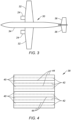
FIG. 3 is a schematic illustration of an aircraft with an aircraft airframe which may include the thermoplastic composite component. -
FIG. 4 is a partial schematic sectional illustration of layers of the thermoplastic composite component. -
FIG. 5 is a flow diagram of a method for manufacturing a thermoplastic composite component. -
FIG. 6 is a partial schematic sectional illustration of a system for ultrasonic welding an arrangement of thermoplastic components together. -
FIG. 7 is a partial schematic sectional illustration of layers of energy transmission material. -
FIG. 8 is a partial schematic sectional illustration of the system for ultrasonic welding another arrangement of thermoplastic components together. -
FIG. 9 is a partial schematic illustration of a repaired thermoplastic composite component. -
FIG. 10 is a partial schematic sectional illustration of the repaired thermoplastic composite component ofFIG. 9 . -
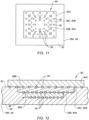
FIG. 11 is a partial schematic illustration of another repaired thermoplastic composite component. -
FIG. 12 is a partial schematic sectional illustration of the repaired thermoplastic composite component ofFIG. 11 . -
FIG. 13 is a partial schematic sectional illustration of the system for ultrasonic welding another arrangement of thermoplastic components together. - The present disclosure includes methods and systems for manufacturing a component 20 (e.g., a thermoplastic composite component), an exemplary embodiment of which is shown in
FIG. 1 . The term "manufacturing" may describe a process for original manufacturing thecomponent 20; e.g., creating a brand new component. The term "manufacturing" may also or alternatively describe a process for remanufacturing or otherwise repairing thecomponent 20; e.g., restoring one or more features of a previously formed component to brand new condition, similar to brand new condition, better than brand new condition, etc. Thecomponent 20, for example, may be repaired to fix one or more defects (e.g., delamination, cracks, wear and/or other damage) imparted during previous use of thecomponent 20. Thecomponent 20 may also or alternatively be repaired to fix one or more defects imparted during the initial formation of thecomponent 20. - The
component 20 may be any component of an aircraft which is constructed from or otherwise includes thermoplastic composite material. Referring toFIG. 2 , the aircraft component may be configured as or otherwise included as part of anacelle 22 for apropulsion system 24 of the aircraft. The aircraft component, for example, may be (or may be part of) a component of anacelle inlet structure 26; e.g., a nacelle inlet lip (e.g., a nose lip), a nacelle outer barrel, a nacelle inner barrel, etc. In another example, the aircraft component may be (or may be part of) another component of thepropulsion system nacelle 22 such as a cowl 28 (e.g., a fan cowl), or the like. Referring toFIG. 3 , the aircraft component may alternatively be configured as or otherwise included as part of anairframe 30 of the aircraft. The aircraft component, for example, may be (or may be part of) anaircraft wing 32, anaircraft fuselage skin 34, anaircraft stabilizer 36, or the like. The aircraft component may still alternatively be configured as or otherwise included as part of a structure within theaircraft airframe 30; e.g., within a cabin of the aircraft. The present disclosure, however, is not limited to manufacturing the foregoing exemplary aircraft components. Moreover, it is contemplated the manufacturing methods of the present disclosure may be utilized for non-aircraft components. - The
component 20 ofFIG. 1 includes at least (or only) a first thermoplasticcomposite body 38A ("first body") and a second thermoplasticcomposite body 38B ("second body") welded to thefirst body 38A; e.g., at one ormore weld locations 39. Referring toFIG. 4 , each of these thermoplasticcomposite bodies thermoplastic matrix 40 and fiber-reinforcement 42 embedded within thethermoplastic matrix 40. - Examples of the
thermoplastic matrix 40 include, but are not limited to, a semi-crystalline thermoplastic resin and an amorphous thermoplastic resin. Examples of the semi-crystalline thermoplastic resin include polyester, polyoxymethylene (POM), polyamide (PA), polyarylene sulfide, polyketone (PK), polyetherketone (PEK), polyether ether ketone (PEEK), polyether ketone ketone (PEKK), polyvinylidene fluoride (PVDF), polytetrafluoroethylene (PTFE), polyaryletherketone (PAEK), polyether nitrile (PEN), fluororesin, and liquid crystal polymer (LCP). Examples of the polyester include polyethylene terephthalate (PET), polybutylene terephthalate (PBT), polytrimethylene terephthalate (PTT), polyethylene naphthalate (PEN), and liquid crystal polyester. An example of the polyarylene sulfide is polyphenylene sulfide (PPS). An example of the fluororesin is polytetrafluoroethylene. Examples of the amorphous thermoplastic resin include polycarbonate (PC), polymethyl methacrylate (PMMA), polyphenylene ether (PPE), polyimide (PI), polyamide imide (PAI), polyetherimide (PEI), polysulfone (PSU), polyether sulfone (PES), and polyarylate (PAR). The present disclosure, however, is not limited to the foregoing exemplary thermoplastic matrix materials. - The fiber-
reinforcement 42 may be arranged in one ormore layers 44 within the respective thermoplasticcomposite body 38 and itsthermoplastic matrix 40. Eachlayer 44 of the fiber-reinforcement 42 may include a plurality of fiber-reinforcement fibers such as metal fibers, carbon fibers, insulating fibers, organic fibers, and inorganic fibers. Examples of the metal fibers include aluminum fibers, brass fibers, and stainless steel fibers. Examples of the carbon fibers include graphite fibers such as polyacrylonitrile (PAN)-based carbon fibers, rayon-based carbon fibers, lignin-based carbon fibers, and pitch-based carbon fibers. An example of the insulating fibers is glass fibers; e.g., fiberglass fibers. Examples of the organic fibers include aramid fibers, polyparaphenylene benzoxazole (PBO) fibers, polyphenylene sulfide fibers, polyester fibers, acrylic fibers, nylon fibers, and polyethylene fibers. Examples of the inorganic fibers include silicon carbide fibers and silicon nitride fibers. The present disclosure, however, is not limited to the foregoing exemplary fiber-reinforcement materials. - The fiber-
reinforcement 42 in eachlayer 44 of the respective thermoplasticcomposite body 38 may entirely be a common (the same) fiber-reinforcement material. Alternatively, the fiber-reinforcement 42 in one or more or all of thelayers 44 may include multiple different fiber-reinforcement materials within thesame layer 44.Different layers 44 within the respective thermoplasticcomposite body 38 may also or alternatively be configured with different fiber-reinforcement materials between thoselayers 44; e.g., onelayer 44 may include a first material or combination of materials and anotherlayer 44 may include a second material or combination of materials. Some or all of the fibers within arespective layer 44 may be continuous fibers. Some or all of the fibers within arespective layer 44 may also or alternatively be chopped fibers. Some or all of the fibers within arespective layer 44 may be unidirectional. Some or all of the fibers within arespective layer 44 may alternatively be multidirectional; e.g., in a woven sheet, a mat of chopped fibers, etc. The present disclosure, however, is not limited to the foregoing exemplary fiber types and/or fiber arrangements. Moreover, while each thermoplasticcomposite body 38 is described above as including the fiber-reinforcement 42, it is contemplated one or more of these thermoplasticcomposite bodies 38 may alternatively be configured without any the fiber-reinforcement 42 embedded within thethermoplastic matrix 40. -
FIG. 5 is a flow diagram of amethod 500 for manufacturing a component; e.g., a thermoplastic composite component. This manufacturing may be an original manufacturing of the component or a repair (e.g., remanufacturing) of the component. For ease of description, themanufacturing method 500 is described below with reference to thecomponent 20 ofFIG. 1 ; e.g., the aircraft component. The present disclosure, however, is not limited to manufacturing such an exemplary component. - In
step 502, thefirst body 38A is provided. Thisfirst body 38A, for example, may be formed using one or more known thermoplastic formation techniques. Examples of such formation techniques include, but are not limited to, laminating, molding, pressing, injection molding, overmolding, and stamping between a plurality of dies. In another example, thefirst body 38A may be cut out from stock material; e.g., a sheet of thermoplastic composite material, prepreg material, etc. This material may then be shaped (if needed) to provide thefirst body 38A. In still another example, thefirst body 38A may be a damagedcomponent 46 to be repaired using themanufacturing method 500. - In
step 504, thesecond body 38B is provided. Thissecond body 38B, for example, may be formed using one or more known thermoplastic formation techniques. Examples of such formation techniques include, but are not limited to, laminating, molding, pressing, injection molding, overmolding, and stamping between a plurality of dies. In another example, thesecond body 38B may be cut out from stock material; e.g., a sheet of thermoplastic composite material, prepreg material, etc. This material may then be shaped (if needed) to provide thesecond body 38B. Where thefirst body 38A is the damagedcomponent 46 to be repaired using themanufacturing method 500, thesecond body 38B may be configured as (or part of) a patch to repair thefirst body 38A. - In
step 506, thefirst body 38A is arranged for ultrasonic welding. For example, referring toFIG. 6 , thefirst body 38A may be disposed on arigid support structure 48; e.g., a metal anvil or die. Thefirst body 38A ofFIG. 6 has a thickness that extends vertically between and to a first (e.g., lower)surface 50 of thefirst body 38A and a second (e.g., upper) surface 52 of thefirst body 38A. The first body first surface 50 ofFIG. 6 is abutted against and contacts a (e.g., upper)support surface 54 of therigid support structure 48. The first bodyfirst surface 50, for example, may lay against (e.g., rest on, be disposed in full contact with, be disposed flat against, etc.) the supportstructure support surface 54. While thesurfaces FIG. 6 , it is contemplated thesurfaces FIG. 6 . Moreover, thesurfaces FIG. 6 . For example, thesurfaces FIG. 6 , thefirst body 38A may be (e.g., temporarily) secured to therigid support structure 48, or thefirst body 38A may simply rest against therigid support structure 48. - In
step 508, thesecond body 38B is arranged with thefirst body 38A for the ultrasonic welding. For example, thesecond body 38B ofFIG. 6 is disposed on thefirst body 38A. Thesecond body 38B ofFIG. 6 has a thickness that extends vertically between and to a first (e.g., lower)surface 56 of thesecond body 38B and a second (e.g., upper) surface 58 of thesecond body 38B. The second body first surface 56 ofFIG. 6 is abutted against and contacts the first bodysecond surface 52. The second bodyfirst surface 56, for example, may lay against (e.g., rest on, be disposed in full contact with, be disposed flat against, etc.) the first bodysecond surface 52. While thesurfaces FIG. 6 , it is contemplated thesurfaces FIG. 6 . Moreover, thesurfaces FIG. 6 . For example, thesurfaces FIG. 6 , thefirst body 38A is disposed vertically between (e.g., may completely separate) and contacts therigid support structure 48 and thesecond body 38B. Here, the (still discrete, non-welded) thermoplasticcomposite bodies 38 are arranged in astack 60 on / over therigid support structure 48. Thesecond body 38B may be (e.g., temporarily) secured to therigid support structure 48 and/or thefirst body 38A, or thesecond body 38B may simply rest against thefirst body 38A. - In
step 510, energy transmission material 62 (e.g., an ultrasonic welding coupling stack) is arranged with the thermoplasticcomposite body stack 60. For example, theenergy transmission material 62 ofFIG. 6 is disposed on at least (or only) thesecond body 38B. Theenergy transmission material 62 ofFIG. 6 has a thickness that extends vertically between and to a first (e.g., lower)surface 64 of theenergy transmission material 62 and a second (e.g., upper) surface 66 of theenergy transmission material 62. The support materialfirst surface 64 ofFIG. 6 is abutted against and contacts the second bodysecond surface 58. The support materialfirst surface 64, for example, may lay against (e.g., rest on, be disposed in full contact with, be disposed flat against, etc.) the second bodysecond surface 58. While thesurfaces FIG. 6 , it is contemplated the surfaces may alternatively have non-straight-line (e.g., curved, compound, etc.) sectional geometries in the plane ofFIG. 6 . Moreover, thesurfaces FIG. 6 . For example, thesurfaces FIG. 6 , thecomposite body stack 60 and itselements rigid support structure 48 and theenergy transmission material 62. Thesecond body 38B ofFIG. 6 is disposed vertically between (e.g., may completely separate) and contacts thefirst body 38A and theenergy transmission material 62. Theenergy transmission material 62 may be (e.g., temporarily) secured to therigid support structure 48 and/or thecomposite body stack 60 and itssecond body 38B, or theenergy transmission material 62 may simply rest against thecomposite body stack 60 and itssecond body 38B. - The
energy transmission material 62 is configured to provide a physical buffer between thecomposite body stack 60 and an ultrasonic horn 68 (e.g., a sonotrode) used for the ultrasonic welding. Theenergy transmission material 62 may enable the normal vibration of theultrasonic horn 68 to be absorbed by the weld pieces (e.g., 38A and 38B) as a normal vibration that will create friction between the weld plate to create the initial heating to start the welding process and weld the thermoplasticcomposite bodies 38 together. Without the support material, the normal vibration may be transformed into transverse and/or bending waves that transport the energy away from the intended weld zone and can cause hot spots in the weld pieces (e.g., 38A and 38B) away from the intended weld area or even at the weld piece edges. Thisenergy transmission material 62 may be a flexible (e.g., non-rigid, compliant, pliable, etc.) body. Referring toFIG. 7 , theenergy transmission material 62 and its body may include one ormore layers 70A-D (generally referred to as "70"). Each of these layers 70 may be a flexible layer of material. Theenergy transmission material 62 and its body, for example, may include one or more layers of flexible elastomer or plastic material. Examples of the elastomer material include polytetrafluoroethylene (e.g., Teflon®), fluoroelastomer, silicone rubber, chlorosulphonated polyethene rubber, ethylene-propylene-diene monomer, hydrogenated acrylonitrile-butadiene rubber and polyurethane, where fiber reinforcement may or may not be disposed within a matrix of the elastomer material. Theenergy transmission material 62 and its body may also or alternatively include one or more layers of flexible elastomeric material. It is contemplated, however, one or more of the layers 70 may alternatively be formed from a more rigid material such as metal. Examples of the metal include stainless steel, titanium (Ti), copper (Cu) and bronze. Theenergy transmission material 62 and its body, for example, may also include one or more layers of metal; e.g., sheet metal layers, metal plates, etc. The present disclosure, however, is not limited to the foregoing exemplary energy transmission material compositions nor layer arrangements. - In
step 512, theultrasonic horn 68 is arranged with theenergy transmission material 62 for the ultrasonic welding. Atip 72 of theultrasonic horn 68 ofFIG. 6 , for example, is positioned over theenergy transmission material 62 and its support materialsecond surface 66. Theultrasonic horn 68 and itstip 72 also engage (e.g., contact) theenergy transmission material 62 and its support materialsecond surface 66. In particular, theultrasonic horn 68 ofFIG. 6 extends vertically along a vertical axis 74 (e.g., a centerline of the ultrasonic horn 68) in a direction towards theelements horn tip 72. Theultrasonic horn 68 ofFIG. 6 is coupled to anultrasonic transducer 76. - In
step 514, the thermoplasticcomposite bodies 38 are ultrasonic welded together using theultrasonic horn 68. Theultrasonic transducer 76, for example, is configured to move (e.g., translate, oscillate, etc.) theultrasonic horn 68 back-and-forth (e.g., vertically up-and-down) along thevertical axis 74 during the ultrasonic welding. Oscillating forces (e.g., pressing and releasing) from this movement of theultrasonic horn 68 are transferred through theenergy transmission material 62 into the thermoplasticcomposite body stack 60 and heat the thermoplastic matrix 40 (seeFIG. 4 ) of thefirst body 38A and thesecond body 38B. The heating softens and then locally melts thethermoplastic matrix 40 and thereby welds thesecond body 38B to thefirst body 38A at and about a point 78 laterally aligned with theultrasonic horn 68; e.g., theweld location 39. Meanwhile, theenergy transmission material 62 provides a buffer between theultrasonic horn 68 and the thermoplasticcomposite bodies 38 being welded together. Providing this buffer may reduce or prevent deformation and/or marring of thesecond body 38B and its second bodysecond surface 58 by theultrasonic horn 68. In addition to the foregoing, by locating theenergy transmission material 62 above the thermoplastic composite body stack 60 (e.g., between thesecond body 38B and the ultrasonic horn 68), theenergy transmission material 62 may be readily and easily moved during themanufacturing method 500. For example, theenergy transmission material 62 may be moved to ensure proper placement relative to theultrasonic horn 68. Theenergy transmission material 62 may also be moved to facilitate further welding as discussed below. - In
step 516, at least (or only) thewelding step 514 may be repeated one or more times at different lateral locations along the thermoplasticcomposite body stack 60 to weld thesecond body 38B to thefirst body 38A at one or more additional locations. Thesecond body 38B may thereby be spot welded to thefirst body 38A to form thecomponent 20. In other embodiments, however, thesecond body 38B may also or alternatively be continuous welded and/or discontinuous welded to thefirst body 38A to form thecomponent 20 at one or more weld joints. During the continuous welding, the weld pieces (e.g., 38A and 38B) under theultrasonic horn 68 are at different stages of the welding process. At a leading edge of theultrasonic horn 68, the process is in the initial phase of heating (friction based) while at the trailing edge of theultrasonic horn 68 the process is in the final stage in which heat is generated by internal viscoelastic heating. - In
step 518, following the welding (e.g., steps 514, 516) theenergy transmission material 62 is removed from thesecond body 38B. For example, while theenergy transmission material 62 provides a buffer between thesecond body 38B and theultrasonic horn 68 during the ultrasonic welding (e.g., steps 514, 516), theenergy transmission material 62 may remain detached (e.g., unwelded) from thesecond body 38B during and following the ultrasonic welding. In particular, theenergy transmission material 62 is not welded to thesecond body 38B during or following the ultrasonic welding of thesecond body 38B to thefirst body 38A (e.g., steps 514, 516). Theenergy transmission material 62 may thereby further function as a release sheet against thesecond body 38B. Theenergy transmission material 62 may be lifted off thecomponent 20 and itssecond body 38B, for example, without requiring an additional process; e.g., milling, machining, scraping, etc. Moreover, theenergy transmission material 62 may be readily moved to facilitate the additionalultrasonic welding step 516 as needed. - While the
component 20 ofFIG. 6 includes the two welded thermoplasticcomposite bodies 38, it is contemplated thecomponent 20 may alternatively include one or more additional thermoplastic composite bodies. For example, referring toFIG. 8 , a third thermoplasticcomposite body 38C ("third body") may be ultrasonic welded to thesecond body 38B, for example, following the ultrasonic welding of thesecond body 38B to thefirst body 38A. The welding of thethird body 38C may be performed using the steps described above where the energy transmission material 62 (or different energy transmission material) is arranged between thethird body 38C and theultrasonic horn 68. - Referring to
FIGS. 9 and 10 , where thefirst body 38A is the damagedcomponent 46 being repaired, each body (e.g., 38B, 38C) ultrasonic welded (directly or indirectly) to thefirst body 38A is configured as (or part of) apatch 80 for thefirst body 38A. Thepatch 80 ofFIG. 10 may be arranged to cover a damagedportion 82 of thefirst body 38A. Afirst layer 84A (e.g., thesecond body 38B) of thepatch 80 ofFIG. 10 , for example, contacts the first body second surface 52 (e.g., an exterior surface of thefirst body 38A) and extends over the damagedportion 82 of thefirst body 38A. Thisfirst patch layer 84A is ultrasonic welded to thefirst body 38A. Asecond layer 84B (e.g., thethird body 38C) of thepatch 80 ofFIG. 10 contacts thefirst patch layer 84A and may also contact the first bodysecond surface 52. Thissecond patch layer 84B is ultrasonic welded to thefirst patch layer 84A and may also be ultrasonic welded to thefirst body 38A. - Referring to
FIGS. 11 and 12 , thepatch 80 may alternatively be arranged to at least partially or completely replace the damaged portion of thefirst body 38A. For example, some or all of the damaged portion of thefirst body 38A may be removed from thefirst body 38A via one or more removal techniques; e.g., machining, milling, cutting, blasting, etc. Referring toFIG. 12 , this removal may form anaperture 86 in thefirst body 38A. Theaperture 86 ofFIG. 12 projects (e.g., partially) vertically into thefirst body 38A from its first body second surface 52 (e.g., an exterior surface of thefirst body 38A) to one or moreinterior surfaces first body 38A. Following this removal, layers 84A-C (generally referred to as "84") of the patch 80 (e.g., eachbody aperture 86 and welded to thefirst body 38A. Thefirst patch layer 84A ofFIG. 12 contacts the innermostinterior surface 88A. Thefirst patch layer 84A is ultrasonic welded to thefirst body 38A. Thesecond patch layer 84B ofFIG. 12 contacts thefirst patch layer 84A and may also contact the next outwardinterior surface 88B. Thesecond patch layer 84B is ultrasonic welded to thefirst patch layer 84A and may also be ultrasonic welded to thefirst body 38A. Thethird patch layer 84C ofFIG. 12 is disposed outside of theaperture 86. Thethird patch layer 84C contacts thesecond patch layer 84B and may also contact the first bodysecond surface 52. Thethird patch layer 84C is ultrasonic welded to thesecond patch layer 84B and may also be ultrasonic welded to thefirst body 38A. - In some embodiments, referring to
FIGS. 10 and12 , the first body second surface 52 (along with the exposed patch layer) may at least partially or completely form an exterior surface of the repaired component. This exterior surface may also be an aerodynamic flow surface of the repaired component. In other embodiments, referring toFIG. 6 , the first bodyfirst surface 50 may at least partially or completely form an exterior surface of thecomponent 20. This exterior surface may also be an aerodynamic flow surface of thecomponent 20. Note, by arranging the aerodynamic flow surface against therigid support structure 48, a shape and contour of the aerodynamic flow surface may be preserved during the ultrasonic welding. - In some embodiments, referring to
FIG. 13 , theenergy transmission material 62 may contact more than one of the thermoplasticcomposite bodies 38 simultaneously. Theenergy transmission material 62 ofFIG. 13 , for example, is arranged over and alongedges 90 ofmultiple bodies 38; e.g., patch layers. This may facilitate an increase in weld area. Moreover, the flexible nature of theenergy transmission material 62 may reduce or prevent deformation to theedges 90. Theenergy transmission material 62, for example, may partially or completely conform to contours of theedges 90. - As described above, the
energy transmission material 62 is disposed between theultrasonic horn 68 and thecomposite bodies 38 being ultrasonic welded using theultrasonic horn 68. Theenergy transmission material 62 may therefore be placed on top of thecomposite bodies 38 being ultrasonic welded. With such an arrangement, theenergy transmission material 62 may be easily moved and/or otherwise adjusted in preparation for and/or during the ultrasonic welding. Theenergy transmission material 62 may also be readily removed following the ultrasonic welding. By contrast, if theenergy transmission material 62 was disposed below the composite body /bodies 38 being ultrasonic welded such that thecomposite bodies 38 are between theultrasonic horn 68 and theenergy transmission material 62, movement, adjustment and/or removal of theenergy transmission material 62 may be significantly more difficult. In addition to the foregoing, by utilizing theenergy transmission material 62 between theultrasonic horn 68 and thecomposite bodies 38 being ultrasonic welded, use of an energy director (e.g., a thermoplastic film) between thecomposite bodies 38 may be omitted. For example, thecomposite bodies FIG. 6 may directly contact one another without any intermediate material (e.g., the energy director) therebetween. This may further simplify the ultrasonic welding process. - While various embodiments of the present invention have been disclosed, it will be apparent to those of ordinary skill in the art that many more embodiments and implementations are possible within the scope of the invention. For example, the present invention as described herein includes several aspects and embodiments that include particular features. Although these features may be described individually, it is within the scope of the present invention that some or all of these features may be combined with any one of the aspects and remain within the scope of the invention. Accordingly, the present invention is not to be restricted except in light of the attached claims and their equivalents.
Claims (15)
- A method, comprising:arranging a first thermoplastic composite body (38A) on a rigid support structure (48), the first thermoplastic composite body (38A) contacting the rigid support structure (48);arranging a second thermoplastic composite body (38B) on the first thermoplastic composite body (38A), the second thermoplastic composite body (38B) contacting the first thermoplastic composite body (38A);arranging energy transmission material (62) on the second thermoplastic composite body (38B), wherein the first thermoplastic composite body (38A) and the second thermoplastic composite body (38B) are disposed between the rigid support structure (48) and the energy transmission material (62); andultrasonic welding the second thermoplastic composite body (38B) to the first thermoplastic composite body (38A) using an ultrasonic horn (68), wherein the energy transmission material (62) is arranged between the second thermoplastic composite body (38B) and the ultrasonic horn (68).
- The method of claim 1, wherein the energy transmission material (62) comprises one or more flexible layers (70A-D) of material.
- The method of claim 1, wherein the energy transmission material (62) comprises one or more layers (70A-D) of elastomeric material,
wherein, optionally, the elastomeric material comprises at least one of polytetrafluoroethylene, fluoroelastomer, silicone rubber, chlorosulphonated polyethene rubber, ethylene-propylene-diene monomer, hydrogenated acrylonitrile-butadiene rubber or polyurethane. - The method of claim 1, wherein the energy transmission material (62) comprises one or more layers (70A-D) of metal.
- The method of any preceding claim, further comprising lifting the energy transmission material (62) off of the second thermoplastic composite body (38B) following the ultrasonic welding.
- The method of any preceding claim, wherein the energy transmission material (62) is not welded to the second thermoplastic composite body (38B) during the ultrasonic welding.
- The method of any preceding claim, wherein:the energy transmission material (62) contacts the second thermoplastic composite body (38B), and, optionally, the energy transmission material (62) further contacts the first thermoplastic composite body (38A); and/orthe second thermoplastic composite body (38B) contacts an exterior surface (52) of the first thermoplastic composite body (38A).
- The method of any preceding claim, wherein:an aperture (86) extends into the first thermoplastic composite body (38A) from an exterior surface (52) of the first thermoplastic composite body (38A) to an interior surface (88A) of the first thermoplastic composite body (38A); andthe second thermoplastic composite body (38B) contacts the interior surface (88A).
- The method of claim 8, further comprising:removing the energy transmission material (62) from the second thermoplastic composite body (38B) following the ultrasonic welding of the second thermoplastic composite body (38B) to the first thermoplastic composite body (38A);arranging a third thermoplastic composite body (38C) on the second thermoplastic composite body (38B) and within the aperture (86);arranging the energy transmission material (62) or additional energy transmission material (62) on the third thermoplastic composite body (38C); andultrasonic welding the third thermoplastic composite body (38C) to the second thermoplastic composite body (38B) using the ultrasonic horn (68).
- The method of claim 8 or 9, further comprising removing a damaged portion of the first thermoplastic composite body (38A) to form the aperture (86) in the first thermoplastic composite body (38A).
- The method of any preceding claim, wherein:the ultrasonic horn (68) extends along a vertical axis (74) to a tip (72) engaged with the energy transmission material (62); andthe ultrasonic horn (68) moves vertically up and down along the vertical axis (74) during the ultrasonic welding.
- The method of any preceding claim, further comprising:providing an aircraft component (20);wherein the aircraft component (20) includes the first thermoplastic composite body (38A) and the second thermoplastic composite body (38B) welded to the first thermoplastic composite body (38A),wherein, optionally, a surface (50) of the first thermoplastic composite body (38A) which contacts the rigid support structure (48) during the ultrasonic welding at least partially forms an exterior aerodynamic flow surface of the aircraft component (20).
- The method of any preceding claim, wherein at least one of the first thermoplastic composite body (38A) or the second thermoplastic composite body (38B) comprises a semi-crystalline thermoplastic resin or an amorphous thermoplastic resin.
- A method for manufacturing an aircraft component (20), comprisingproviding a first thermoplastic composite body (38A);arranging a second thermoplastic composite body (38B) on the first thermoplastic composite body (38A);arranging energy transmission material (62) on the second thermoplastic composite body (38B), wherein the second thermoplastic composite body (38B) is disposed between and contacts the first thermoplastic composite body (38A) and the energy transmission material (62);ultrasonic welding the second thermoplastic composite body (38B) to the first thermoplastic composite body (38A) using an ultrasonic horn (68), wherein the energy transmission material (62) is arranged between the second thermoplastic composite body (38B) and the ultrasonic horn (68); andlifting the energy transmission material (62) off of the second thermoplastic composite body (38B) following the ultrasonic welding;wherein the aircraft component (20) includes the first thermoplastic composite body (38A) and the second thermoplastic composite body (38B) welded to the first thermoplastic composite body (38A).
- A repair method, comprising:providing an aircraft component (20) comprising a first thermoplastic composite body (38A);arranging a second thermoplastic composite body (38B) on the first thermoplastic composite body (38A);arranging energy transmission material (62) on the second thermoplastic composite body (38B), wherein the second thermoplastic composite body (38B) is disposed between and contacts the first thermoplastic composite body (38A) and the energy transmission material (62); andultrasonic welding the second thermoplastic composite body (38B) to the first thermoplastic composite body (38A) using an ultrasonic horn (68) to at least partially repair a damaged portion of the first thermoplastic composite body (38A), wherein the energy transmission material (62) is arranged between the second thermoplastic composite body (38B) and the ultrasonic horn (68),wherein, optionally, the method further comprises:removing the damaged portion from the first thermoplastic composite body (38A) to form an aperture (86) in the first thermoplastic composite body (38A);the arranging of the second thermoplastic composite body (38B) comprising disposing the second thermoplastic composite body (38B) within the aperture (86) and onto an interior surface (88A) of the first thermoplastic composite body (38A).
Applications Claiming Priority (2)
| Application Number | Priority Date | Filing Date | Title |
|---|---|---|---|
| US202363468172P | 2023-05-22 | 2023-05-22 | |
| US18/235,385 US20240391179A1 (en) | 2023-05-22 | 2023-08-18 | Ultrasonic welding thermoplastic material using energy transmission material |
Publications (1)
| Publication Number | Publication Date |
|---|---|
| EP4467322A1 true EP4467322A1 (en) | 2024-11-27 |
Family
ID=91226951
Family Applications (1)
| Application Number | Title | Priority Date | Filing Date |
|---|---|---|---|
| EP24177304.3A Pending EP4467322A1 (en) | 2023-05-22 | 2024-05-22 | Ultrasonic welding thermoplastic material using energy transmission material |
Country Status (2)
| Country | Link |
|---|---|
| US (1) | US20240391179A1 (en) |
| EP (1) | EP4467322A1 (en) |
Cited By (1)
| Publication number | Priority date | Publication date | Assignee | Title |
|---|---|---|---|---|
| EP4585405A1 (en) * | 2024-01-10 | 2025-07-16 | Rohr, Inc. | Delamination and edge damage repair on thermoplastic composites |
Citations (2)
| Publication number | Priority date | Publication date | Assignee | Title |
|---|---|---|---|---|
| JPH08336897A (en) * | 1995-06-09 | 1996-12-24 | Tonen Chem Corp | Method for connecting stretchable film |
| WO2015018377A1 (en) * | 2013-08-08 | 2015-02-12 | GM Global Technology Operations LLC | Apparatus and processes for protecting an ultrasonic welding horn using a thin-film separator |
Family Cites Families (7)
| Publication number | Priority date | Publication date | Assignee | Title |
|---|---|---|---|---|
| JPS63139726A (en) * | 1986-12-01 | 1988-06-11 | Nitsushiyoo:Kk | Welding method for thermoplastic resin |
| NL1024630C2 (en) * | 2003-10-27 | 2005-04-28 | Martin Theodoor De Groot | Method for applying a thermoplastic plastic insert unit in a thermoplastic plastic sandwich product. |
| FR2887800B1 (en) * | 2005-07-04 | 2011-02-11 | Eads Ccr Groupement Dinteret Economique | ULTRASONIC ASSEMBLY METHOD OF AT LEAST TWO RIGID PIECES |
| JP2010143156A (en) * | 2008-12-20 | 2010-07-01 | Fujita Kikai:Kk | Ultrasonic welding process |
| US12194690B2 (en) * | 2018-06-20 | 2025-01-14 | Spirit Aerosystems, Inc. | System and method for welding thermoplastic components to create composite structure |
| KR20240038802A (en) * | 2021-08-18 | 2024-03-25 | 애자일 울트라소닉스 코포레이션 | Ultrasonic Integration of Materials |
| US12617164B2 (en) * | 2024-01-10 | 2026-05-05 | Rohr, Inc. | Delamination and edge damage repair on thermoplastic composites |
-
2023
- 2023-08-18 US US18/235,385 patent/US20240391179A1/en active Pending
-
2024
- 2024-05-22 EP EP24177304.3A patent/EP4467322A1/en active Pending
Patent Citations (2)
| Publication number | Priority date | Publication date | Assignee | Title |
|---|---|---|---|---|
| JPH08336897A (en) * | 1995-06-09 | 1996-12-24 | Tonen Chem Corp | Method for connecting stretchable film |
| WO2015018377A1 (en) * | 2013-08-08 | 2015-02-12 | GM Global Technology Operations LLC | Apparatus and processes for protecting an ultrasonic welding horn using a thin-film separator |
Cited By (2)
| Publication number | Priority date | Publication date | Assignee | Title |
|---|---|---|---|---|
| EP4585405A1 (en) * | 2024-01-10 | 2025-07-16 | Rohr, Inc. | Delamination and edge damage repair on thermoplastic composites |
| US12617164B2 (en) | 2024-01-10 | 2026-05-05 | Rohr, Inc. | Delamination and edge damage repair on thermoplastic composites |
Also Published As
| Publication number | Publication date |
|---|---|
| US20240391179A1 (en) | 2024-11-28 |
Similar Documents
| Publication | Publication Date | Title |
|---|---|---|
| AU2002249955B2 (en) | Forming structural assemblies with 3-D woven joint pre-forms | |
| US9302759B2 (en) | Flexible truss frame and method of making the same | |
| JP6273804B2 (en) | Manufacturing method of fiber reinforced plastic molding | |
| US20240391179A1 (en) | Ultrasonic welding thermoplastic material using energy transmission material | |
| JP6272202B2 (en) | Bending part in composite panel | |
| US11358345B2 (en) | Internal tooling for composite parts | |
| EP3747637B1 (en) | Method to integrate a first part and a second part comprising composite material | |
| EP2808155A2 (en) | Joint assembly and method of assembling the same | |
| US20060172121A1 (en) | Cellular composite grid-stiffened structure | |
| EP4215349A1 (en) | Resistance repair of thermoplastic components | |
| EP4585405A1 (en) | Delamination and edge damage repair on thermoplastic composites | |
| EP3392027B1 (en) | Systems and methods for assembling elongate composite structures | |
| WO2019031478A1 (en) | Fiber reinforced plastic and fiber reinforced plastic manufacturing method | |
| JP2008544887A (en) | Ultrasonic assembly method | |
| CN118107195A (en) | Curing tool | |
| EP4088912A1 (en) | Welding method and structure | |
| EP4497578A1 (en) | Horizontal ultrasonic welding thermoplastic material | |
| EP4215344B1 (en) | Vibration welding fiber-reinforced composite aircraft structures | |
| EP4631701A1 (en) | Continuous ultrasonic welding thermoplastic material for aerospace component repair | |
| EP1031406A1 (en) | Forming reinforcing components | |
| EP4197757A2 (en) | Systems and methods for themoplastic panel manufacturing | |
| US20240001621A1 (en) | Vibration welding method and system | |
| US20260048561A1 (en) | Repair delamination in thermoplastic component with horizontal ultrasonic welding | |
| EP4397472A1 (en) | Method of ultrasonic welding thermoplastic composite components | |
| US20240375356A1 (en) | Vibration welding method |
Legal Events
| Date | Code | Title | Description |
|---|---|---|---|
| PUAI | Public reference made under article 153(3) epc to a published international application that has entered the european phase |
Free format text: ORIGINAL CODE: 0009012 |
|
| STAA | Information on the status of an ep patent application or granted ep patent |
Free format text: STATUS: THE APPLICATION HAS BEEN PUBLISHED |
|
| AK | Designated contracting states |
Kind code of ref document: A1 Designated state(s): AL AT BE BG CH CY CZ DE DK EE ES FI FR GB GR HR HU IE IS IT LI LT LU LV MC ME MK MT NL NO PL PT RO RS SE SI SK SM TR |
|
| STAA | Information on the status of an ep patent application or granted ep patent |
Free format text: STATUS: REQUEST FOR EXAMINATION WAS MADE |
|
| 17P | Request for examination filed |
Effective date: 20250527 |