EP4467296A1 - Anthropomorphic metamorphic dexterous hand - Google Patents
Anthropomorphic metamorphic dexterous hand Download PDFInfo
- Publication number
- EP4467296A1 EP4467296A1 EP23183642.0A EP23183642A EP4467296A1 EP 4467296 A1 EP4467296 A1 EP 4467296A1 EP 23183642 A EP23183642 A EP 23183642A EP 4467296 A1 EP4467296 A1 EP 4467296A1
- Authority
- EP
- European Patent Office
- Prior art keywords
- finger
- pulp
- unit
- finger pulp
- module
- Prior art date
- Legal status (The legal status is an assumption and is not a legal conclusion. Google has not performed a legal analysis and makes no representation as to the accuracy of the status listed.)
- Granted
Links
Images




Classifications
-
- B—PERFORMING OPERATIONS; TRANSPORTING
- B25—HAND TOOLS; PORTABLE POWER-DRIVEN TOOLS; MANIPULATORS
- B25J—MANIPULATORS; CHAMBERS PROVIDED WITH MANIPULATION DEVICES
- B25J15/00—Gripping heads and other end effectors
- B25J15/0009—Gripping heads and other end effectors comprising multi-articulated fingers, e.g. resembling a human hand
-
- B—PERFORMING OPERATIONS; TRANSPORTING
- B25—HAND TOOLS; PORTABLE POWER-DRIVEN TOOLS; MANIPULATORS
- B25J—MANIPULATORS; CHAMBERS PROVIDED WITH MANIPULATION DEVICES
- B25J15/00—Gripping heads and other end effectors
- B25J15/02—Gripping heads and other end effectors servo-actuated
- B25J15/0206—Gripping heads and other end effectors servo-actuated comprising articulated grippers
- B25J15/0233—Gripping heads and other end effectors servo-actuated comprising articulated grippers actuated by chains, cables or ribbons
-
- B—PERFORMING OPERATIONS; TRANSPORTING
- B25—HAND TOOLS; PORTABLE POWER-DRIVEN TOOLS; MANIPULATORS
- B25J—MANIPULATORS; CHAMBERS PROVIDED WITH MANIPULATION DEVICES
- B25J9/00—Program-controlled manipulators
- B25J9/08—Program-controlled manipulators characterised by modular constructions
-
- Y—GENERAL TAGGING OF NEW TECHNOLOGICAL DEVELOPMENTS; GENERAL TAGGING OF CROSS-SECTIONAL TECHNOLOGIES SPANNING OVER SEVERAL SECTIONS OF THE IPC; TECHNICAL SUBJECTS COVERED BY FORMER USPC CROSS-REFERENCE ART COLLECTIONS [XRACs] AND DIGESTS
- Y02—TECHNOLOGIES OR APPLICATIONS FOR MITIGATION OR ADAPTATION AGAINST CLIMATE CHANGE
- Y02A—TECHNOLOGIES FOR ADAPTATION TO CLIMATE CHANGE
- Y02A50/00—TECHNOLOGIES FOR ADAPTATION TO CLIMATE CHANGE in human health protection, e.g. against extreme weather
- Y02A50/30—Against vector-borne diseases, e.g. mosquito-borne, fly-borne, tick-borne or waterborne diseases whose impact is exacerbated by climate change
Definitions
- the present invention relates to the technical field of robots, and in particular to, an anthropomorphic metamorphic dexterous hand.
- Manipulators can replace human hands to execute a plurality of tasks in complex and harsh environments.
- Traditional manipulators are provided with fully rigid palms and fingers in order to adapt to grabbing scenarios requiring high load-bearing capacity, but the flexibility and control capability are limited.
- driving mechanisms of the manipulators require complex structural design, which causes the manipulators to be redundant and complex, high in cost and low in reliability.
- the manipulators need to have certain flexibility while having overall rigidity, but conventional manipulators cannot meet the above requirements.
- the present invention aims at solving at least one of the technical problems in the existing technology. Therefore, the present invention provides an anthropomorphic metamorphic dexterous hand, which can take into account both the rigidity and flexibility of a manipulator.
- An anthropomorphic metamorphic dexterous hand including:
- the anthropomorphic metamorphic dexterous hand according to the embodiment of the present invention at least has the following advantageous effects.
- the finger pulp unit has a greater flexibility than the finger pulp unit.
- the finger pulp unit When executing a grabbing task, the finger pulp unit has a high degree of fit with an object to be grabbed and can adapt to the shape of the object to be grabbed to realize stable grabbing.
- the finger pulp unit and the finger back unit realize the combination of flexibility and hardness.
- the finger back unit provides a certain degree of rigid support for the finger module, and the finger pulp unit has higher flexibility, which facilitates the finger module to bend towards the finger pulp unit, and conforms to the characteristic that human fingers can only bend towards the palm center.
- the finger module has both rigidity and flexibility, and meets the requirements for rigidity and flexibility of a manipulator in different grabbing environments.
- the finger pulp unit includes a plurality of finger pulp connectors which are arranged in a length direction of the finger module, edges of adjacent finger pulp connectors which are close to each other are connected to form a finger pulp bending part, and the finger pulp bending part has a smaller thickness than the finger pulp connector.
- the finger back unit includes a plurality of finger back connectors which are arranged in the length direction of the finger module, edges of adjacent finger back connectors which are close to each other are connected to form a finger back bending part, and the finger back bending part has a smaller thickness than the finger back connector.
- the finger back bending part and the finger pulp bending part are oppositely arranged in a bending direction of the finger module.
- the plurality of finger pulp connectors are arranged in a width direction of the finger module, edges of adjacent finger pulp connectors in the width direction which are close to each other are connected to form a transition part, and the transition part is recessed away from the finger back unit.
- the plurality of finger back connectors are arranged in the width direction of the finger module, edges of adjacent finger back connectors in the width direction which are close to each other are connected to form a reinforcing part, and the reinforcing part protrudes towards the finger pulp unit and is located between adjacent finger pulp units.
- the finger back unit and the finger pulp unit are connected to form an integrated structure.
- the finger back connector and the finger pulp connector are mutually adhered at opposite sides, and the finger back bending part and the finger pulp bending part are provided in a separate structure.
- the finger back connector includes four finger back connecting surfaces which are connected end to end in sequence at side edges thereof, and vertexes of the four finger back connecting surfaces are overlapped to form finger back vertex angles.
- the finger pulp connector includes four finger pulp connecting surfaces which are connected end to end in sequence at side edges thereof, and vertexes of the four finger pulp connecting surfaces are overlapped to form finger pulp vertex angles.
- An opening of the finger pulp vertex angle in the width direction of the finger module is not smaller than that of the finger pulp vertex angle.
- the finger pulp connector is provided with a notch at the edge, the notches of adjacent finger pulp connectors are oppositely arranged, and the notches are located at the finger pulp bending part.
- the finger pulp connector is provided with notches at two opposite sides in the length direction, the notches of adjacent finger pulp connector are oppositely arranged, the notches are located at the finger pulp bending part, and the notch at the side facing away from the finger pulp unit is larger than the notch at the side facing the finger pulp unit.
- the finger pulp connector is internally provided with a first cavity penetrating through the finger pulp connector in the length direction, the first cavities of adjacent finger pulp connectors are communicated with each other, the finger back connector is internally provided with a second cavity penetrating through the finger back connector in the length direction, and the second cavities of adjacent finger back connectors are communicated with each other.
- the finger back unit is internally provided with a guide hole penetrating through the finger back unit in the length direction, the guide holes of adjacent finger back units are communicated with each other, the finger back traction wire is threaded in the guide holes in sequence, and the finger pulp traction wire is threaded in the first cavities in sequence.
- the palm driving unit is provided in two, one of the palm connecting rods includes two support arms, and the two palm driving units are respectively mounted on the two support arms and configured to drive the palm connecting rods connected to the support arms to rotate.
- the finger module includes a fixed seat, the finger driving unit, the finger back unit and the finger pulp unit are all mounted on the fixed seat, and the fixed seat is detachably connected with the palm connecting rod.
- “several” means one or more, and "a plurality of” means two or more.
- the terms such as “greater than”, “less than”, “exceeding” and the like are understood as excluding the following number, while “above”, “below”, “within” and the like are understood as including the following number.
- the terms such as “first”, “second” and the like are only used for distinguishing technical features, and are not to be construed as indicating or implying relative importance or implying the number or a precedence order of indicated technical features.
- an embodiment of the present invention provides an anthropomorphic metamorphic dexterous hand, which includes a palm module 100 and a plurality of finger modules 200, which are mounted on the palm module 100.
- the palm module 100 and the finger modules 200 are respectively configured to simulate the palm and fingers of a human hand, and the plurality of finger modules 200 cooperate to execute corresponding grabbing tasks.
- the palm module 100 includes a plurality of palm connecting rods 110 and a palm driving unit 120.
- the plurality of palm connecting rods 110 are rotationally connected end to end in sequence and enclosed to form a closed-loop structure, and the palm driving unit 120 is connected to some of the palm connecting rods 110 to drive adjacent palm connecting rods 110 to rotate relatively.
- three to five finger modules 200 are provided, and the finger modules 200 are mounted on only some palm connecting rods 110.
- only some palm connecting rods 110 are directly driven by the palm driving unit 120 to rotate, and other palm connecting rods 110 are driven by another palm driving unit 120 connected therewith to rotate.
- the palm module 100 can present different configurations, so that the finger module 200 can change different grabbing angles, and therefore can be adapted to grabbing requirements in various task environments.
- the finger module 200 includes a finger back unit 210, a finger pulp unit 220 and a finger driving unit 230.
- the finger back unit 210 and the finger pulp unit 220 are stacked, and the finger pulp unit 220 has a greater flexibility than the finger back unit 210.
- the finger back unit 210 is internally threaded with a finger back traction wire 240, and the finger pulp unit 220 is internally threaded with a finger pulp traction wire 250.
- One end of the finger back traction wire 240 is connected to a tail end of the finger back unit 210, and the other end of the finger back traction wire is connected to the finger driving unit 230.
- the finger driving unit 230 is configured to drive the finger back traction wire 240 and the finger pulp traction wire 250 to retract and extend to enable the finger module 200 to bend towards the finger pulp unit 220 or stretch away from the finger pulp unit 220.
- the finger module 200 in an initial state assumes a linear shape, and the finger driving unit 230 pulls the finger pulp traction wire 250 to tighten and at the same time releases the finger back traction wire 240.
- the finger pulp unit 220 is pulled by the finger back traction wire 240 to bend and curl, while the finger back unit 210 is not pulled by the finger back traction wire 240, but is driven by the finger pulp unit 220 to bend synchronously with the finger pulp unit 220.
- the finger module 200 can execute a grabbing task.
- the finger driving unit 230 tightens the finger back traction wire 240 while releasing the finger back traction wire 250.
- the finger back unit 210 is pulled by the finger back traction wire 240 to stretch from a bending state, while the finger back unit 220 is not pulled by the finger back traction wire 250, but is driven by the finger back unit 210 to synchronously stretch, so that the finger module 200 returns to the initial state at which the finger module 200 releases the grabbed object.
- the anthropomorphic metamorphic dexterous hand in the present invention highly restores an effect of cooperation between the palm and fingers when a human hand performs a grabbing action.
- the palm wraps and contracts in a direction of a palm center, and each finger bends and curls towards the palm center.
- the plurality of palm connecting rods 110 of the palm module 100 can change configuration and rotate towards the palm center of the palm module 100 under the drive of the palm driving unit 120.
- the finger driving unit 230 of the finger module 200 pulls the finger back unit 210 and the finger pulp unit 220 to bend through the traction wires, to envelop the object between the finger module 200 and the palm center by cooperating with the contraction of the palm module 100, thereby completing the grabbing task.
- the finger pulp unit 220 is set to have a greater flexibility than the finger back unit 210 in the present invention.
- the finger pulp unit 220 contacts an object to be grabbed, and the finger pulp unit 220 with higher flexibility has a high degree of fit with the object to be grabbed and thus can be adapted to the shape of the object to be grabbed to realize stable grabbing without causing damage to the object to be grabbed due to hard contact and collision with the object to be grabbed.
- the finger pulp unit 220 and the finger back unit 210 realize the combination of flexibility and hardness.
- the finger back unit 210 has a higher hardness than the finger pulp unit 220, and the finger pulp unit 220 has a higher flexibility than the finger back unit 210.
- the finger back unit 210 provides a certain degree of rigid support for the finger module 200 to prevent an overall flexibility of the finger module 200 from being too large and affecting the structural strength.
- the finger pulp unit 220 has higher flexibility, which facilitates the finger module 200 to bend towards the finger pulp unit 220, and conforms to the characteristic that human fingers can only bend towards the palm center.
- the finger module 200 has both rigidity and flexibility, and meets the requirements for the rigidity and flexibility of a manipulator in different grabbing environments.
- each finger module 200 is connected to a different palm connecting rod 110, the finger modules 200 bend in different directions, but all bend towards the palm center of the palm module 100, and when the finger module 200 bends, the finger back unit 210 bends towards the finger pulp unit 220.
- the finger pulp unit 220 includes a plurality of finger pulp connectors 221 arranged in a length direction of the finger module 200, edges of adjacent finger pulp connectors 221 which are close to each other are connected to form a finger pulp bending part 222, and the finger pulp bending part 222 has a smaller thickness than the finger pulp connector 221. In this way, the plurality of finger pulp connectors 221 are connected to form the finger pulp unit 220.
- the finger pulp unit 220 bends based on a joint of adjacent finger pulp connectors 221, that is, the finger pulp bending part 222. Because the finger pulp bending part 222 has a smaller thickness, the bending of the finger pulp unit 220 is more convenient.
- the finger back unit 210 includes a plurality of finger back connectors 211 arranged in the length direction of the finger module 200, edges of adjacent finger back connectors 211 which are close to each other are connected to form a finger back bending part 212, and the finger back bending part 212 has a smaller thickness than the finger back connector 211. In this way, the plurality of finger back connectors 211 are connected to form the finger back unit 210.
- the finger back unit 210 bends based on a joint of the adjacent finger back connectors 211, that is, the finger back bending part 212. Because the finger back bending part 212 has a smaller thickness, the bending of the finger back unit 210 is more convenient.
- the finger back bending part 212 and the finger pulp bending part 222 are oppositely arranged in the bending direction of the finger module 200.
- the bending positions of the finger back unit 210 and the finger pulp unit 220 are matched, so as to avoid that the bending of the finger back unit 210 and the bending of the finger pulp unit 220 interfere with each other during the bending of the finger module 200 due to the misalignment of the bending positions of the finger back unit 210 and the finger pulp unit 220, and affect the grabbing efficiency.
- the plurality of finger pulp connectors 221 are arranged in a width direction of the finger module 200, edges of adjacent finger pulp connectors 221 in the width direction which are close to each other are connected to form a transition part 223, and the transition part 223 is recessed away from the finger back unit 210.
- the plurality of finger back connectors 211 are arranged in the width direction of the finger module 200, edges of adjacent finger back connectors 211 in the width direction which are close to each other are connected to form a reinforcing part 213, and the reinforcing part 213 protrudes towards the finger pulp units 220 and is located between adjacent finger pulp units 220.
- the finger pulp connectors 221 and the finger back connectors 211 are arranged in the width direction, which can increase a grabbing surface of the finger module 200 and a contact area between the finger module 200 and the object to be grabbed, and improve an envelope degree of the finger module 200 to the object to be grabbed. Moreover, due to an increased distance in the width direction of the finger back unit 210, the strength of the finger module 200 in the width direction is increased, avoiding deformation of the finger module 200 in the width direction when the finger module 200 bends, and improving the stability of the finger module 200 in grabbing.
- the transition part 223 of the finger pulp unit 220 cooperates with the reinforcing part 213 of the finger back unit 210, and the reinforcing part 213 abuts against an adjacent finger pulp unit 220 in the width direction. Since the finger back unit 210 has a higher strength than the finger pulp unit 220, the strength of the finger module 200 in the width direction can be further improved, preventing the finger module 200 from stretching or bending in the width direction.
- the length direction refers to an overall extension direction of the finger module 200, and the finger module 200 extends away from the palm module 100, which conforms to the basic form of a human hand.
- the width direction refers to an arrangement direction of adj acent finger modules 200.
- the plurality of finger pulp connectors 221 arranged in the length direction form a finger pulp bending group
- the plurality of finger back connectors 211 arranged in the length direction form a finger back bending group.
- both the finger pulp bending group and finger back bending group are provided in multiple, and adjacent finger pulp connecting groups are connected by a transition part 223, and adjacent finger back connecting groups are connected by a reinforcing part 213.
- each finger pulp connecting group is internally threaded with one finger pulp traction wire 250, and the number of finger pulp traction wires 250 in one finger module 200 is the same as that of the finger pulp connectors 221 arranged in the width direction.
- each finger back connection group is internally threaded with one finger back traction wire 240, and the number of finger back traction wires 240 in one finger module 200 is the same as that of the finger back connectors 211 arranged in the width direction.
- the influence of the flexibility of the finger back unit 210 and the finger pulp unit 220 on traction accuracy can be reduced, the finger back bending group and the finger pulp bending group in the same finger module 200 can bend synchronously, and the traction effects of the traction wires on different regions of the finger back unit 210 and the finger pulp unit 220 are relatively uniform, thus improving the grabbing strength of the finger module 200 to the object to be grabbed.
- the finger back connector 211 includes four finger back connecting surfaces 2111 which are connected end to end in sequence at side edges thereof, and vertexes of the four finger back connecting surfaces 2111 are overlapped to form finger back vertex angles 2112.
- the side edges of adjacent finger back connecting surfaces 2111 are connected with each other to form combination ridges
- each finger back connector 211 includes four combination ridges, where two combination ridges extend in the width direction of the finger module 200 and are located at opposite sides of the finger back vertex angle 2112, and another two combination ridges extend in the length direction of the finger module 200 and are located at the opposite sides of the finger back vertex angle 2112.
- Fig. 5 the finger back connector 211 includes four finger back connecting surfaces 2111 which are connected end to end in sequence at side edges thereof, and vertexes of the four finger back connecting surfaces 2111 are overlapped to form finger back vertex angles 2112.
- the side edges of adjacent finger back connecting surfaces 2111 are connected with each other to form combination ridges
- each finger back connector 211 includes four combination ridges
- the finger pulp connector 221 includes four finger pulp connecting surfaces 2211 which are connected end to end in sequence at side edges thereof, and vertexes of the four finger pulp connecting surfaces 2211 are overlapped to form finger pulp vertex angles 2212.
- the side edges of adjacent finger pulp connecting surfaces 2211 are connected with each other to form combination ridges
- each finger pulp connector 221 includes four combination ridges, where two combination ridges extend in the width direction of the finger module 200 and are located at the opposite sides of the finger pulp vertex angle 2212, and another two combination ridges extend in the length direction of the finger module 200 and are located at the opposite sides of the finger pulp vertex angle 2212.
- the finger pulp vertex angles 2212 are located at the side of the finger pulp unit 220 facing away from the bending direction, and the finger back vertex angles 2112 are located at the side of the finger back unit 210 facing away from the bending direction.
- the finger back vertex angles 2112 are located at the side of the finger pulp vertex angles 2212 facing away from the bending direction, and the combination ridges of the finger back connector 211 correspond to the combination ridges of the finger pulp connector 221 in position in the bending direction of the finger module 200.
- the opening of the finger back vertex angle 2112 is set to be not smaller than that of the finger pulp vertex angle 2212, and two combination ridges extending in the width direction of the finger back finger unit 210 can provide greater support in the width direction. Since the finger back unit 210 has a greater hardness than the finger pulp unit 220, the finger back unit 210 can provide greater support for the finger pulp unit 220 in the width direction, thereby improving the strength of the finger module 200 in the width direction, and reducing the retraction and bending of the finger module 200 in the width direction.
- the finger back unit 210 and the finger pulp unit 220 are connected to form an integrated structure. That is, the finger back unit 210 and the finger pulp unit 220 are integrally formed without post-assembly. On the one hand, the assembly difficulty of the finger module 200 is reduced, and on the other hand, the matching accuracy between the finger back bending part 212 and the finger pulp bending part 222 is high, so that the finger module 200 has high bending performance.
- the finger back unit 210 and the finger pulp unit 220 are formed by injection molding, 3D printing or other processing methods.
- the finger back connector 211 and the finger pulp connector 221 are mutually adhered at opposite sides, and the finger back bending part 212 and the finger pulp bending part 222 are provided in a separate structure. Therefore, in the stacking direction of the finger back unit 210 and the finger pulp unit 220, the finger back connector 211 and the finger pulp connector 221 are mutually adhered, so that the finger back unit 210 and the finger pulp unit 220 form an integrated structure and can bend synchronously, and thus the connection is simple and quick.
- the finger back bending part 212 and the finger pulp bending part 222 are not connected and are independent from each other, the influence of adhering on the bending performance of the finger module 200 can be reduced, allowing the finger back bending part 212 and the finger pulp bending part 222 to bend freely, and improving the bending flexibility of the finger module 200.
- the finger pulp connector 221 is provided with a notch 2213 at the edge, and the notches 2213 of adjacent finger pulp connectors 221 in the length direction are oppositely arranged. After the adjacent finger pulp connectors 221 in the length direction are connected with each other, the two notches 2213 are butted with each other and combined to form a closed through hole, and the notches 2213 are just located at the finger pulp bending part 222.
- the flexibility of the finger pulp unit 220 can be further improved, and the degree of squeezing experienced by the finger pulp bending part 222 at the side facing away from the finger back unit 210 during bending can be reduced, enabling the bending of the finger pulp unit 220 to be more flexible.
- the finger pulp connector 221 is provided with notches 2213 at two opposite sides in the length direction, and the notches 2213 of adjacent finger pulp connectors 221 in the length direction are oppositely arranged. After the adjacent finger pulp connectors 221 in the length direction are connected with each other, the two notches 2213 are butted with each other and combined to form a closed through hole, and the notches 2213 are just located at the finger pulp bending part 222.
- the notch 2213 at the side facing away from the finger back unit 210 is set to be larger than the notch 2213 at the side facing the finger back unit 210.
- the finger pulp unit 220 is provided with notches 2213 at both sides, which can improve the flexibility of the finger pulp unit 220 during bending and stretching, and further improve the flexibility of the finger pulp unit 220. Moreover, because the finger module 200 faces away from the finger back unit 210 during bending, setting the notch 2213 at the side facing away from the finger back unit 210 to be larger than the notch 2213 at the side facing the finger back unit 210 is more conducive to the bending of the finger pulp unit 220 and enables the bending of the finger module 200 to be more flexible.
- the finger pulp connector 221 is internally provided with a first cavity 2214 penetrating therethrough in the length direction, and the first cavities 2214 of adjacent finger pulp connectors 221 are communicated with each other. Because the finger pulp connector 221 is internally hollow, the finger pulp unit 220 has higher flexibility, and thus can generate greater deformation when bending to adapt to the shape of the object to be grabbed. Similarly, the finger back connector 211 is internally provided with a second cavity 2113 penetrating therethrough in the length direction, which allows the finger back unit 210 to possess a certain degree of flexibility and can better bend when pulled by the finger back traction wire 240 or driven by the finger pulp unit 220.
- the finger back connector 211 is internally provided with a guide hole 2114 penetrating therethrough in the length direction, the guide holes 2114 of adjacent finger back units 210 are communicated with each other, and the finger back traction wire 240 is threaded in the guide holes 2114 in sequence.
- the finger back traction wire 240 is guided by the guide holes 2114 to retract and extend in the length direction of the finger module 200, and is prevented from swinging in the finger back connector 211.
- the finger back unit 210 has certain hardness, forming the guide hole 2114 in the finger back unit 210 can accurately define the bending direction of the finger module 200 and improve the grabbing accuracy of the anthropomorphic metamorphic dexterous hand.
- the finger pulp traction wires 250 are directly threaded in the first cavities 2214 of the plurality of finger pulp units 220, and are configured to pull the finger pulp units 220 by means of the first cavities 2214.
- the guide hole 2114 is formed at the center of the finger back connector 211 in the width direction, so that traction forces applied to different regions of the finger back connector 211 in the width direction are more uniform, and grabbing performed by the finger module 200 on the object to be grabbed is more stable.
- the finger module 200 further includes a fixed seat 260.
- the finger driving unit 230, the finger back unit 210 and the finger pulp unit 220 are all mounted on the fixed seat 260, and the fixed seat 260 is detachably connected with the palm connecting rod 110.
- the finger module 200 is mounted as an integrated structure on the palm connecting rod 110, and when an internal structure of the finger module 200 fails, the finger module 200 can be directly disassembled for maintenance.
- the finger driving unit 230 is located in the finger module 200 and is not associated with the palm driving unit 120, which can reduce the interference between different drive elements in the anthropomorphic metamorphic dexterous hand, allowing the structure of the anthropomorphic metamorphic dexterous hand to be simpler and the motion control faster.
- a decelerating motor may be provided as the finger driving unit 230.
- the finger driving unit 230 is mounted inside the fixed seat 260, the fixed seat 260 is internally provided with a winding roller 270, and the finger back traction wire 240 or the finger pulp traction wire 250 is wound around the winding roller 270.
- the winding roller 270 is connected with and driven by the finger driving unit 230 to rotate, so as to wind the finger back traction wire 240 or the finger pulp traction wire 250 around the winding roller 270 or release the traction wires from the winding roller 270.
- Two winding rollers 270 are arranged in the fixed seat 260 in the stacking direction of the finger back unit 210 and the finger pulp unit 220, and the two winding rollers 270 are configured to wind the finger back traction wire 240 and the finger pulp traction wire 250 respectively.
- each winding roller 270 may be driven by a respective finger driving unit 230, or two winding rollers 270 may share one finger driving unit 230.
- the finger back unit 210 and the finger pulp unit 220 are connected to an outer wall of the fixed seat 260.
- the fixed seat 260 is internally provided with a finger back wire guiding hole 261 extending towards the finger back unit 210 and a finger pulp wire guiding hole 261 extending towards the finger pulp unit 220, the finger back traction wire 240 is led out from the winding roller 270 to the finger back wire guiding hole 261 and introduced into the guide hole 2114 in the finger back unit 210 through the guidance of the finger back wire guiding hole 261.
- the finger pulp traction wire 250 is led out from the winding roller 270 to the finger pulp wire guiding hole 261 and introduced into the first cavity 2214 in the finger pulp unit 220 through the guidance of the finger pulp wire guiding hole 261.
- the palm driving unit 120 is provided in two, one of the palm connecting rods 110 includes two support arms 111, and the two palm driving units 120 are respectively mounted on the two support arms 111 and configured to drive the palm connecting rods 110 connected to the support arms 111 to rotate.
- the rotation of the two palm connecting rods 110 can further drive other palm connecting rods 110 rotationally connected with the two palm connecting rods 110 to rotate, so that the palm module 100 can be transformed into a corresponding configuration.
- the two support arms 111 provide a mounting foundation for the palm driving units 120, so that the palm driving units 120 are integrated into the palm module 100, and the shape of the anthropomorphic metamorphic dexterous hand is more concise.
- the anthropomorphic metamorphic dexterous hand further includes a base 300.
- the palm connecting rod 110 with two support arms 111 is rotationally connected to the base 300.
- the palm connecting rod 110 rotates relative to the base 300, the positions of the palm module 100 and the finger modules 200 can be changed, and the finger modules 200 can grab objects to be grabbed at different positions, thus enlarging the grabbing range of the anthropomorphic metamorphic dexterous hand.
Landscapes
- Engineering & Computer Science (AREA)
- Robotics (AREA)
- Mechanical Engineering (AREA)
- Manipulator (AREA)
Abstract
Description
- The present invention relates to the technical field of robots, and in particular to, an anthropomorphic metamorphic dexterous hand.
- Manipulators can replace human hands to execute a plurality of tasks in complex and harsh environments. Traditional manipulators are provided with fully rigid palms and fingers in order to adapt to grabbing scenarios requiring high load-bearing capacity, but the flexibility and control capability are limited. In addition, driving mechanisms of the manipulators require complex structural design, which causes the manipulators to be redundant and complex, high in cost and low in reliability. Furthermore, in practical use occasions, in order to better simulate human hands to work and execute corresponding grabbing tasks, the manipulators need to have certain flexibility while having overall rigidity, but conventional manipulators cannot meet the above requirements.
- The present invention aims at solving at least one of the technical problems in the existing technology. Therefore, the present invention provides an anthropomorphic metamorphic dexterous hand, which can take into account both the rigidity and flexibility of a manipulator.
- An anthropomorphic metamorphic dexterous hand is provided according to an embodiment of the present invention, including:
- a palm module including a plurality of palm connecting rods and a palm driving unit, where the plurality of palm connecting rods are rotationally connected end to end in sequence and enclosed to form a closed-loop structure, and the palm driving unit is connected to some of the palm connecting rods to drive adjacent palm connecting rods to rotate relatively; and
- a plurality of finger modules, some of the palm connecting rods being provided with one of the finger modules, and the finger module including a finger back unit, a finger pulp unit and a finger driving unit, where the finger back unit and the finger pulp unit are stacked, the finger pulp unit has a greater flexibility than the finger back unit, the finger back unit is internally threaded with a finger back traction wire, the finger pulp unit is internally threaded with a finger pulp traction wire, one end of the finger back traction wire is connected to a tail end of the finger back unit, the other end of the finger back traction wire is connected to the finger driving unit, one end of the finger pulp traction wire is connected to the tail end of the finger pulp unit, the other end of the finger pulp traction wire is connected to the finger driving unit, and the finger driving unit is configured to drive the finger back traction wire and the finger pulp traction wire to retract and extend to enable the finger module to bend towards the finger pulp unit or stretch away from the finger pulp unit.
- The anthropomorphic metamorphic dexterous hand according to the embodiment of the present invention at least has the following advantageous effects.
- In the present invention, the finger pulp unit has a greater flexibility than the finger pulp unit. When executing a grabbing task, the finger pulp unit has a high degree of fit with an object to be grabbed and can adapt to the shape of the object to be grabbed to realize stable grabbing. The finger pulp unit and the finger back unit realize the combination of flexibility and hardness. To be specific, the finger back unit provides a certain degree of rigid support for the finger module, and the finger pulp unit has higher flexibility, which facilitates the finger module to bend towards the finger pulp unit, and conforms to the characteristic that human fingers can only bend towards the palm center. Thus, the finger module has both rigidity and flexibility, and meets the requirements for rigidity and flexibility of a manipulator in different grabbing environments.
- According to some embodiments of the present invention, the finger pulp unit includes a plurality of finger pulp connectors which are arranged in a length direction of the finger module, edges of adjacent finger pulp connectors which are close to each other are connected to form a finger pulp bending part, and the finger pulp bending part has a smaller thickness than the finger pulp connector.
- The finger back unit includes a plurality of finger back connectors which are arranged in the length direction of the finger module, edges of adjacent finger back connectors which are close to each other are connected to form a finger back bending part, and the finger back bending part has a smaller thickness than the finger back connector.
- The finger back bending part and the finger pulp bending part are oppositely arranged in a bending direction of the finger module.
- According to some embodiments of the present invention, the plurality of finger pulp connectors are arranged in a width direction of the finger module, edges of adjacent finger pulp connectors in the width direction which are close to each other are connected to form a transition part, and the transition part is recessed away from the finger back unit.
- The plurality of finger back connectors are arranged in the width direction of the finger module, edges of adjacent finger back connectors in the width direction which are close to each other are connected to form a reinforcing part, and the reinforcing part protrudes towards the finger pulp unit and is located between adjacent finger pulp units.
- According to some embodiments of the present invention, the finger back unit and the finger pulp unit are connected to form an integrated structure.
- Alternatively, the finger back connector and the finger pulp connector are mutually adhered at opposite sides, and the finger back bending part and the finger pulp bending part are provided in a separate structure.
- According to some embodiments of the present invention, the finger back connector includes four finger back connecting surfaces which are connected end to end in sequence at side edges thereof, and vertexes of the four finger back connecting surfaces are overlapped to form finger back vertex angles.
- The finger pulp connector includes four finger pulp connecting surfaces which are connected end to end in sequence at side edges thereof, and vertexes of the four finger pulp connecting surfaces are overlapped to form finger pulp vertex angles. An opening of the finger pulp vertex angle in the width direction of the finger module is not smaller than that of the finger pulp vertex angle.
- According to some embodiments of the present invention, the finger pulp connector is provided with a notch at the edge, the notches of adjacent finger pulp connectors are oppositely arranged, and the notches are located at the finger pulp bending part.
- According to some embodiments of the present invention, the finger pulp connector is provided with notches at two opposite sides in the length direction, the notches of adjacent finger pulp connector are oppositely arranged, the notches are located at the finger pulp bending part, and the notch at the side facing away from the finger pulp unit is larger than the notch at the side facing the finger pulp unit.
- According to some embodiments of the present invention, the finger pulp connector is internally provided with a first cavity penetrating through the finger pulp connector in the length direction, the first cavities of adjacent finger pulp connectors are communicated with each other, the finger back connector is internally provided with a second cavity penetrating through the finger back connector in the length direction, and the second cavities of adjacent finger back connectors are communicated with each other.
- According to some embodiments of the present invention, the finger back unit is internally provided with a guide hole penetrating through the finger back unit in the length direction, the guide holes of adjacent finger back units are communicated with each other, the finger back traction wire is threaded in the guide holes in sequence, and the finger pulp traction wire is threaded in the first cavities in sequence.
- According to some embodiments of the present invention, the palm driving unit is provided in two, one of the palm connecting rods includes two support arms, and the two palm driving units are respectively mounted on the two support arms and configured to drive the palm connecting rods connected to the support arms to rotate.
- According to some embodiments of the present invention, the finger module includes a fixed seat, the finger driving unit, the finger back unit and the finger pulp unit are all mounted on the fixed seat, and the fixed seat is detachably connected with the palm connecting rod.
- Additional aspects and advantages of the present invention will be set forth in part in the following description, and in part will be apparent from the following description, or may be learned by practice of the present invention.
- The present invention will be further illustrated below in conjunction with the drawings and embodiments, in which:
-
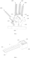
Fig. 1 is a schematic structural diagram of an embodiment of an anthropomorphic metamorphic dexterous hand of the present invention; -
Fig. 2 is a schematic diagram of an embodiment of a finger module; -
Fig. 3 is an explosive schematic diagram of a finger back unit and a finger pulp unit inFig. 2 ; -
Fig. 4 is a sectional view of a finger back unit and a finger pulp unit; -
Fig. 5 is an enlarged view at A inFig. 2 ; -
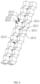
Fig. 6 is a schematic diagram of an embodiment of a finger pulp unit; -
Fig. 7 is a schematic diagram of a finger pulp unit inFig. 6 in another direction; -
Fig. 8 is a schematic diagram of a finger module with a winding roller hidden; and -
Fig. 9 is a schematic diagram of an embodiment of a palm connecting rod. - Reference numerals:
-
palm module 100,palm connecting rod 110,support arm 111,palm driving unit 120; -
finger module 200,finger back unit 210,finger back connector 211, fingerback connecting surface 2111, fingerback vertex angle 2112,second cavity 2113,guide hole 2114, fingerback bending part 212, reinforcingpart 213,finger pulp unit 220,finger pulp connector 221, fingerpulp connecting surface 2211, fingerpulp vertex angle 2212,notch 2213,first cavity 2214, fingerpulp bending part 222,transition part 223,finger driving unit 230, fingerback traction wire 240, fingerpulp traction wire 250, fixedseat 260,wire guiding hole 261,winding roller 270; -
base 300. - Embodiments of the present invention will be described below in detail. Examples of the embodiments are shown in the drawings, where same or similar reference numerals indicate same or similar elements or elements having same or similar functions throughout the drawings. Embodiments described below with reference to the drawings are example embodiments, which are only used for illustrating the present invention, and are not intended to limit the present invention.
- It should be understood in the description of the present invention that terms such as "upper", "lower", "before", "after", "left", "right", etc., indicate directional or positional relationships shown based on the drawings, and are only intended to facilitate the description of the present invention and simplify the description, rather than to indicate or imply that the indicated devices or elements must have a specific orientation or constructed and operated in a specific orientation, and therefore, shall not be understood as a limitation to the present invention.
- In the description of the present invention, "several" means one or more, and "a plurality of" means two or more. The terms such as "greater than", "less than", "exceeding" and the like are understood as excluding the following number, while "above", "below", "within" and the like are understood as including the following number. The terms such as "first", "second" and the like are only used for distinguishing technical features, and are not to be construed as indicating or implying relative importance or implying the number or a precedence order of indicated technical features.
- In the description of the present invention, unless otherwise specifically defined, terms such as "arrangement", "mount," and "connection" shall be understood in a broad sense. For those having ordinary skills in the art, the specific meanings of the above terms in the present invention should be reasonably determined in combination with the specific content of the technical scheme.
- In the description of the present invention, description with reference to the terms "an embodiment", "some embodiments", "illustrative embodiments", "examples", "specific examples" or "some examples" means that the specific features, structures, materials or characteristics described in conjunction with the embodiment or example is included in at least one embodiment or example of the present invention. In this description, the schematic expressions of the above terms do not necessarily refer to the same embodiments or examples. Furthermore, the specific features, structures, materials or characteristics described may be combined in any one or more embodiments or examples in a suitable manner.
- Referring to
Fig. 1 , an embodiment of the present invention provides an anthropomorphic metamorphic dexterous hand, which includes apalm module 100 and a plurality offinger modules 200, which are mounted on thepalm module 100. Thepalm module 100 and thefinger modules 200 are respectively configured to simulate the palm and fingers of a human hand, and the plurality offinger modules 200 cooperate to execute corresponding grabbing tasks. - In an embodiment, the
palm module 100 includes a plurality ofpalm connecting rods 110 and apalm driving unit 120. The plurality ofpalm connecting rods 110 are rotationally connected end to end in sequence and enclosed to form a closed-loop structure, and thepalm driving unit 120 is connected to some of thepalm connecting rods 110 to drive adjacentpalm connecting rods 110 to rotate relatively. In order to facilitate a grabbing action, three to fivefinger modules 200 are provided, and thefinger modules 200 are mounted on only somepalm connecting rods 110. In addition, only somepalm connecting rods 110 are directly driven by thepalm driving unit 120 to rotate, and otherpalm connecting rods 110 are driven by anotherpalm driving unit 120 connected therewith to rotate. Because the plurality ofpalm connecting rods 110 are rotationally connected to form a closed-loop structure, the number ofpalm connecting rods 110 participating in rotation and the degree of freedom of thepalm module 100 are changed under the drive of thepalm driving unit 120, to form thepalm module 100 into a metamorphic mechanism. In this way, thepalm module 100 can present different configurations, so that thefinger module 200 can change different grabbing angles, and therefore can be adapted to grabbing requirements in various task environments. - Referring to
Fig. 2 to Fig. 4 , thefinger module 200 includes a finger backunit 210, afinger pulp unit 220 and afinger driving unit 230. The finger backunit 210 and thefinger pulp unit 220 are stacked, and thefinger pulp unit 220 has a greater flexibility than the finger backunit 210. The finger backunit 210 is internally threaded with a finger backtraction wire 240, and thefinger pulp unit 220 is internally threaded with a fingerpulp traction wire 250. One end of the finger backtraction wire 240 is connected to a tail end of the finger backunit 210, and the other end of the finger back traction wire is connected to thefinger driving unit 230. One end of the fingerpulp traction wire 250 is connected to a tail end of thefinger pulp unit 220, and the other end of the finger pulp traction wire is connected to thefinger driving unit 230. Thefinger driving unit 230 is configured to drive the finger backtraction wire 240 and the fingerpulp traction wire 250 to retract and extend to enable thefinger module 200 to bend towards thefinger pulp unit 220 or stretch away from thefinger pulp unit 220. By means of examples, thefinger module 200 in an initial state assumes a linear shape, and thefinger driving unit 230 pulls the fingerpulp traction wire 250 to tighten and at the same time releases the finger backtraction wire 240. In this case, thefinger pulp unit 220 is pulled by the finger backtraction wire 240 to bend and curl, while the finger backunit 210 is not pulled by the finger backtraction wire 240, but is driven by thefinger pulp unit 220 to bend synchronously with thefinger pulp unit 220. At this time, thefinger module 200 can execute a grabbing task. Thefinger driving unit 230 tightens the finger backtraction wire 240 while releasing the finger backtraction wire 250. In this case, the finger backunit 210 is pulled by the finger backtraction wire 240 to stretch from a bending state, while the finger backunit 220 is not pulled by the finger backtraction wire 250, but is driven by the finger backunit 210 to synchronously stretch, so that thefinger module 200 returns to the initial state at which thefinger module 200 releases the grabbed object. - It should be noted that the anthropomorphic metamorphic dexterous hand in the present invention highly restores an effect of cooperation between the palm and fingers when a human hand performs a grabbing action. For example, when the human hand performs the grabbing action, the palm wraps and contracts in a direction of a palm center, and each finger bends and curls towards the palm center. In the present invention, the plurality of
palm connecting rods 110 of thepalm module 100 can change configuration and rotate towards the palm center of thepalm module 100 under the drive of thepalm driving unit 120. Thefinger driving unit 230 of thefinger module 200 pulls the finger backunit 210 and thefinger pulp unit 220 to bend through the traction wires, to envelop the object between thefinger module 200 and the palm center by cooperating with the contraction of thepalm module 100, thereby completing the grabbing task. - Further, the
finger pulp unit 220 is set to have a greater flexibility than the finger backunit 210 in the present invention. On the one hand, when executing a grabbing task, thefinger pulp unit 220 contacts an object to be grabbed, and thefinger pulp unit 220 with higher flexibility has a high degree of fit with the object to be grabbed and thus can be adapted to the shape of the object to be grabbed to realize stable grabbing without causing damage to the object to be grabbed due to hard contact and collision with the object to be grabbed. On the other hand, thefinger pulp unit 220 and the finger backunit 210 realize the combination of flexibility and hardness. To be specific, the finger backunit 210 has a higher hardness than thefinger pulp unit 220, and thefinger pulp unit 220 has a higher flexibility than the finger backunit 210. The finger backunit 210 provides a certain degree of rigid support for thefinger module 200 to prevent an overall flexibility of thefinger module 200 from being too large and affecting the structural strength. Thefinger pulp unit 220 has higher flexibility, which facilitates thefinger module 200 to bend towards thefinger pulp unit 220, and conforms to the characteristic that human fingers can only bend towards the palm center. Thus, thefinger module 200 has both rigidity and flexibility, and meets the requirements for the rigidity and flexibility of a manipulator in different grabbing environments. - It should be noted that since each
finger module 200 is connected to a differentpalm connecting rod 110, thefinger modules 200 bend in different directions, but all bend towards the palm center of thepalm module 100, and when thefinger module 200 bends, the finger backunit 210 bends towards thefinger pulp unit 220. - In some embodiments, referring to
Fig. 3 , thefinger pulp unit 220 includes a plurality offinger pulp connectors 221 arranged in a length direction of thefinger module 200, edges of adjacentfinger pulp connectors 221 which are close to each other are connected to form a fingerpulp bending part 222, and the fingerpulp bending part 222 has a smaller thickness than thefinger pulp connector 221. In this way, the plurality offinger pulp connectors 221 are connected to form thefinger pulp unit 220. When bending, thefinger pulp unit 220 bends based on a joint of adjacentfinger pulp connectors 221, that is, the fingerpulp bending part 222. Because the fingerpulp bending part 222 has a smaller thickness, the bending of thefinger pulp unit 220 is more convenient. Similarly, the finger backunit 210 includes a plurality of finger backconnectors 211 arranged in the length direction of thefinger module 200, edges of adjacent finger backconnectors 211 which are close to each other are connected to form a finger back bendingpart 212, and the finger back bendingpart 212 has a smaller thickness than the finger backconnector 211. In this way, the plurality of finger backconnectors 211 are connected to form the finger backunit 210. When bending, the finger backunit 210 bends based on a joint of the adjacent finger backconnectors 211, that is, the finger back bendingpart 212. Because the finger back bendingpart 212 has a smaller thickness, the bending of the finger backunit 210 is more convenient. Further, the finger back bendingpart 212 and the fingerpulp bending part 222 are oppositely arranged in the bending direction of thefinger module 200. When thefinger module 200 bends, the bending positions of the finger backunit 210 and thefinger pulp unit 220 are matched, so as to avoid that the bending of the finger backunit 210 and the bending of thefinger pulp unit 220 interfere with each other during the bending of thefinger module 200 due to the misalignment of the bending positions of the finger backunit 210 and thefinger pulp unit 220, and affect the grabbing efficiency. - Further, the plurality of
finger pulp connectors 221 are arranged in a width direction of thefinger module 200, edges of adjacentfinger pulp connectors 221 in the width direction which are close to each other are connected to form atransition part 223, and thetransition part 223 is recessed away from the finger backunit 210. Similarly, the plurality of finger backconnectors 211 are arranged in the width direction of thefinger module 200, edges of adjacent finger backconnectors 211 in the width direction which are close to each other are connected to form a reinforcingpart 213, and the reinforcingpart 213 protrudes towards thefinger pulp units 220 and is located between adjacentfinger pulp units 220. Thefinger pulp connectors 221 and the finger backconnectors 211 are arranged in the width direction, which can increase a grabbing surface of thefinger module 200 and a contact area between thefinger module 200 and the object to be grabbed, and improve an envelope degree of thefinger module 200 to the object to be grabbed. Moreover, due to an increased distance in the width direction of the finger backunit 210, the strength of thefinger module 200 in the width direction is increased, avoiding deformation of thefinger module 200 in the width direction when thefinger module 200 bends, and improving the stability of thefinger module 200 in grabbing. In addition, thetransition part 223 of thefinger pulp unit 220 cooperates with the reinforcingpart 213 of the finger backunit 210, and the reinforcingpart 213 abuts against an adjacentfinger pulp unit 220 in the width direction. Since the finger backunit 210 has a higher strength than thefinger pulp unit 220, the strength of thefinger module 200 in the width direction can be further improved, preventing thefinger module 200 from stretching or bending in the width direction. - It should be noted that the length direction refers to an overall extension direction of the
finger module 200, and thefinger module 200 extends away from thepalm module 100, which conforms to the basic form of a human hand. The width direction refers to an arrangement direction of adj acentfinger modules 200. - The plurality of
finger pulp connectors 221 arranged in the length direction form a finger pulp bending group, and the plurality of finger backconnectors 211 arranged in the length direction form a finger back bending group. When thefinger pulp connectors 221 and finger backconnectors 211 are arranged in multiple, both the finger pulp bending group and finger back bending group are provided in multiple, and adjacent finger pulp connecting groups are connected by atransition part 223, and adjacent finger back connecting groups are connected by a reinforcingpart 213. It should be noted that each finger pulp connecting group is internally threaded with one fingerpulp traction wire 250, and the number of fingerpulp traction wires 250 in onefinger module 200 is the same as that of thefinger pulp connectors 221 arranged in the width direction. Similarly, each finger back connection group is internally threaded with one finger backtraction wire 240, and the number of finger backtraction wires 240 in onefinger module 200 is the same as that of the finger backconnectors 211 arranged in the width direction. In this way, the influence of the flexibility of the finger backunit 210 and thefinger pulp unit 220 on traction accuracy can be reduced, the finger back bending group and the finger pulp bending group in thesame finger module 200 can bend synchronously, and the traction effects of the traction wires on different regions of the finger backunit 210 and thefinger pulp unit 220 are relatively uniform, thus improving the grabbing strength of thefinger module 200 to the object to be grabbed. - In the present invention, referring to
Fig. 5 , the finger backconnector 211 includes four finger back connectingsurfaces 2111 which are connected end to end in sequence at side edges thereof, and vertexes of the four finger back connectingsurfaces 2111 are overlapped to form finger back vertex angles 2112. The side edges of adjacent finger back connectingsurfaces 2111 are connected with each other to form combination ridges, each finger backconnector 211 includes four combination ridges, where two combination ridges extend in the width direction of thefinger module 200 and are located at opposite sides of the finger backvertex angle 2112, and another two combination ridges extend in the length direction of thefinger module 200 and are located at the opposite sides of the finger backvertex angle 2112. Similarly, referring toFig. 6 , thefinger pulp connector 221 includes four fingerpulp connecting surfaces 2211 which are connected end to end in sequence at side edges thereof, and vertexes of the four fingerpulp connecting surfaces 2211 are overlapped to form finger pulp vertex angles 2212. The side edges of adjacent fingerpulp connecting surfaces 2211 are connected with each other to form combination ridges, eachfinger pulp connector 221 includes four combination ridges, where two combination ridges extend in the width direction of thefinger module 200 and are located at the opposite sides of the fingerpulp vertex angle 2212, and another two combination ridges extend in the length direction of thefinger module 200 and are located at the opposite sides of the fingerpulp vertex angle 2212. - It should be noted that the finger pulp vertex angles 2212 are located at the side of the
finger pulp unit 220 facing away from the bending direction, and the finger back vertex angles 2112 are located at the side of the finger backunit 210 facing away from the bending direction. After the finger backunit 210 and thefinger pulp unit 220 are stacked, the finger back vertex angles 2112 are located at the side of the finger pulp vertex angles 2212 facing away from the bending direction, and the combination ridges of the finger backconnector 211 correspond to the combination ridges of thefinger pulp connector 221 in position in the bending direction of thefinger module 200. In this embodiment, in the width direction of thefinger module 200, the opening of the finger backvertex angle 2112 is set to be not smaller than that of the fingerpulp vertex angle 2212, and two combination ridges extending in the width direction of the finger backfinger unit 210 can provide greater support in the width direction. Since the finger backunit 210 has a greater hardness than thefinger pulp unit 220, the finger backunit 210 can provide greater support for thefinger pulp unit 220 in the width direction, thereby improving the strength of thefinger module 200 in the width direction, and reducing the retraction and bending of thefinger module 200 in the width direction. - In an embodiment, the finger back
unit 210 and thefinger pulp unit 220 are connected to form an integrated structure. That is, the finger backunit 210 and thefinger pulp unit 220 are integrally formed without post-assembly. On the one hand, the assembly difficulty of thefinger module 200 is reduced, and on the other hand, the matching accuracy between the finger back bendingpart 212 and the fingerpulp bending part 222 is high, so that thefinger module 200 has high bending performance. By means of examples, the finger backunit 210 and thefinger pulp unit 220 are formed by injection molding, 3D printing or other processing methods. - In other embodiments, the finger back
connector 211 and thefinger pulp connector 221 are mutually adhered at opposite sides, and the finger back bendingpart 212 and the fingerpulp bending part 222 are provided in a separate structure. Therefore, in the stacking direction of the finger backunit 210 and thefinger pulp unit 220, the finger backconnector 211 and thefinger pulp connector 221 are mutually adhered, so that the finger backunit 210 and thefinger pulp unit 220 form an integrated structure and can bend synchronously, and thus the connection is simple and quick. In addition, since the finger back bendingpart 212 and the fingerpulp bending part 222 are not connected and are independent from each other, the influence of adhering on the bending performance of thefinger module 200 can be reduced, allowing the finger back bendingpart 212 and the fingerpulp bending part 222 to bend freely, and improving the bending flexibility of thefinger module 200. - In the present invention, referring to
Fig. 6 andFig. 7 , thefinger pulp connector 221 is provided with anotch 2213 at the edge, and thenotches 2213 of adjacentfinger pulp connectors 221 in the length direction are oppositely arranged. After the adjacentfinger pulp connectors 221 in the length direction are connected with each other, the twonotches 2213 are butted with each other and combined to form a closed through hole, and thenotches 2213 are just located at the fingerpulp bending part 222. By forming thenotch 2213 in thefinger pulp connector 221, the flexibility of thefinger pulp unit 220 can be further improved, and the degree of squeezing experienced by the fingerpulp bending part 222 at the side facing away from the finger backunit 210 during bending can be reduced, enabling the bending of thefinger pulp unit 220 to be more flexible. - In another embodiment, the
finger pulp connector 221 is provided withnotches 2213 at two opposite sides in the length direction, and thenotches 2213 of adjacentfinger pulp connectors 221 in the length direction are oppositely arranged. After the adjacentfinger pulp connectors 221 in the length direction are connected with each other, the twonotches 2213 are butted with each other and combined to form a closed through hole, and thenotches 2213 are just located at the fingerpulp bending part 222. Thenotch 2213 at the side facing away from the finger backunit 210 is set to be larger than thenotch 2213 at the side facing the finger backunit 210. In this way, thefinger pulp unit 220 is provided withnotches 2213 at both sides, which can improve the flexibility of thefinger pulp unit 220 during bending and stretching, and further improve the flexibility of thefinger pulp unit 220. Moreover, because thefinger module 200 faces away from the finger backunit 210 during bending, setting thenotch 2213 at the side facing away from the finger backunit 210 to be larger than thenotch 2213 at the side facing the finger backunit 210 is more conducive to the bending of thefinger pulp unit 220 and enables the bending of thefinger module 200 to be more flexible. - In the present invention, referring to
Fig. 3 , thefinger pulp connector 221 is internally provided with afirst cavity 2214 penetrating therethrough in the length direction, and thefirst cavities 2214 of adjacentfinger pulp connectors 221 are communicated with each other. Because thefinger pulp connector 221 is internally hollow, thefinger pulp unit 220 has higher flexibility, and thus can generate greater deformation when bending to adapt to the shape of the object to be grabbed. Similarly, the finger backconnector 211 is internally provided with asecond cavity 2113 penetrating therethrough in the length direction, which allows the finger backunit 210 to possess a certain degree of flexibility and can better bend when pulled by the finger backtraction wire 240 or driven by thefinger pulp unit 220. - Further, referring to
Fig. 4 , the finger backconnector 211 is internally provided with aguide hole 2114 penetrating therethrough in the length direction, the guide holes 2114 of adjacent finger backunits 210 are communicated with each other, and the finger backtraction wire 240 is threaded in the guide holes 2114 in sequence. When driven by thefinger driving unit 230, the finger backtraction wire 240 is guided by the guide holes 2114 to retract and extend in the length direction of thefinger module 200, and is prevented from swinging in the finger backconnector 211. Because the finger backunit 210 has certain hardness, forming theguide hole 2114 in the finger backunit 210 can accurately define the bending direction of thefinger module 200 and improve the grabbing accuracy of the anthropomorphic metamorphic dexterous hand. In addition, the fingerpulp traction wires 250 are directly threaded in thefirst cavities 2214 of the plurality offinger pulp units 220, and are configured to pull thefinger pulp units 220 by means of thefirst cavities 2214. - In addition, the
guide hole 2114 is formed at the center of the finger backconnector 211 in the width direction, so that traction forces applied to different regions of the finger backconnector 211 in the width direction are more uniform, and grabbing performed by thefinger module 200 on the object to be grabbed is more stable. - Referring to
Fig. 2 , thefinger module 200 further includes a fixedseat 260. Thefinger driving unit 230, the finger backunit 210 and thefinger pulp unit 220 are all mounted on the fixedseat 260, and the fixedseat 260 is detachably connected with thepalm connecting rod 110. In this way, thefinger module 200 is mounted as an integrated structure on thepalm connecting rod 110, and when an internal structure of thefinger module 200 fails, thefinger module 200 can be directly disassembled for maintenance. In addition, thefinger driving unit 230 is located in thefinger module 200 and is not associated with thepalm driving unit 120, which can reduce the interference between different drive elements in the anthropomorphic metamorphic dexterous hand, allowing the structure of the anthropomorphic metamorphic dexterous hand to be simpler and the motion control faster. - A decelerating motor may be provided as the
finger driving unit 230. Thefinger driving unit 230 is mounted inside the fixedseat 260, the fixedseat 260 is internally provided with a windingroller 270, and the finger backtraction wire 240 or the fingerpulp traction wire 250 is wound around the windingroller 270. The windingroller 270 is connected with and driven by thefinger driving unit 230 to rotate, so as to wind the finger backtraction wire 240 or the fingerpulp traction wire 250 around the windingroller 270 or release the traction wires from the windingroller 270. Two windingrollers 270 are arranged in the fixedseat 260 in the stacking direction of the finger backunit 210 and thefinger pulp unit 220, and the two windingrollers 270 are configured to wind the finger backtraction wire 240 and the fingerpulp traction wire 250 respectively. In addition, each windingroller 270 may be driven by a respectivefinger driving unit 230, or two windingrollers 270 may share onefinger driving unit 230. - In addition, referring to
Fig. 8 , the finger backunit 210 and thefinger pulp unit 220 are connected to an outer wall of the fixedseat 260. The fixedseat 260 is internally provided with a finger backwire guiding hole 261 extending towards the finger backunit 210 and a finger pulpwire guiding hole 261 extending towards thefinger pulp unit 220, the finger backtraction wire 240 is led out from the windingroller 270 to the finger backwire guiding hole 261 and introduced into theguide hole 2114 in the finger backunit 210 through the guidance of the finger backwire guiding hole 261. The fingerpulp traction wire 250 is led out from the windingroller 270 to the finger pulpwire guiding hole 261 and introduced into thefirst cavity 2214 in thefinger pulp unit 220 through the guidance of the finger pulpwire guiding hole 261. - In the present invention, referring to
Fig. 9 , thepalm driving unit 120 is provided in two, one of thepalm connecting rods 110 includes twosupport arms 111, and the twopalm driving units 120 are respectively mounted on the twosupport arms 111 and configured to drive thepalm connecting rods 110 connected to thesupport arms 111 to rotate. The rotation of the twopalm connecting rods 110 can further drive otherpalm connecting rods 110 rotationally connected with the twopalm connecting rods 110 to rotate, so that thepalm module 100 can be transformed into a corresponding configuration. It should be noted that the twosupport arms 111 provide a mounting foundation for thepalm driving units 120, so that thepalm driving units 120 are integrated into thepalm module 100, and the shape of the anthropomorphic metamorphic dexterous hand is more concise. - In addition, the anthropomorphic metamorphic dexterous hand further includes a
base 300. Thepalm connecting rod 110 with twosupport arms 111 is rotationally connected to thebase 300. When thepalm connecting rod 110 rotates relative to thebase 300, the positions of thepalm module 100 and thefinger modules 200 can be changed, and thefinger modules 200 can grab objects to be grabbed at different positions, thus enlarging the grabbing range of the anthropomorphic metamorphic dexterous hand. - The embodiments of the present invention are described in detail in conjunction with the drawings, but the present invention is not limited thereto, and various modifications may be made within the knowledge of those having ordinary skills in art without departing from the scope of the present invention. In addition, the embodiments in the present invention and the features in the embodiments may be combined with each other if not in collision.
Claims (11)
- An anthropomorphic metamorphic dexterous hand, comprising:a palm module (100) comprising a plurality of palm connecting rods (110) and a palm driving unit (120), wherein the plurality of palm connecting rods (110) are rotationally connected end to end in sequence and enclosed to form a closed-loop structure, and the palm driving unit (120) is connected to some of the palm connecting rods (110) to drive adjacent palm connecting rods (110) to rotate relatively; anda plurality of finger modules (200), some of the palm connecting rods (110) being provided with one of the finger modules (200), and each of the finger modules (200) comprising a finger back unit (210), a finger pulp unit (220) and a finger driving unit (230), wherein the finger back unit (210) and the finger pulp unit (220) are stacked, the finger pulp unit (220) has a greater flexibility than the finger back unit (210), the finger back unit (210) is internally threaded with a finger back traction wire (240), the finger pulp unit (220) is internally threaded with a finger pulp traction wire (250), one end of the finger back traction wire (240) is connected to a tail end of the finger back unit (210), the other end of the finger back traction wire (240) is connected to the finger driving unit (230), one end of the finger pulp traction wire (250) is connected to a tail end of the finger pulp unit (220), the other end of the finger pulp traction wire (250) is connected to the finger driving unit (230), and the finger driving unit (230) is configured to drive the finger back traction wire (240) and the finger pulp traction wire (250) to retract and extend to enable the finger module (200) to bend towards the finger pulp unit (220) or stretch away from the finger pulp unit (220).
- The anthropomorphic metamorphic dexterous hand of claim 1, wherein the finger pulp unit (220) comprises a plurality of finger pulp connectors (221) which are arranged in a length direction of the finger module (200), edges of adjacent finger pulp connectors (221) which are close to each other are connected to form a finger pulp bending part (222), and the finger pulp bending part (222) has a smaller thickness than the finger pulp connector (221);the finger back unit (210) comprises a plurality of finger back connectors (211) which are arranged in the length direction of the finger module (200), edges of adjacent finger back connectors (211) which are close to each other are connected to form a finger back bending part (212), and the finger back bending part (212) has a smaller thickness than the finger back connector (211);wherein the finger back bending part (212) and the finger pulp bending part (222) are oppositely arranged in a bending direction of the finger module (200).
- The anthropomorphic metamorphic dexterous hand of claim 2, wherein the plurality of finger pulp connectors (221) are arranged in a width direction of the finger module (200), edges of adjacent finger pulp connectors (221) in the width direction which are close to each other are connected to form a transition part (223), and the transition part (223) is recessed away from the finger back unit (210); and
the plurality of finger back connectors (211) are arranged in the width direction of the finger module (200), edges of adjacent finger back connectors (211) in the width direction which are close to each other are connected to form a reinforcing part (213), and the reinforcing part (213) protrudes towards the finger pulp unit (220) and is located between adjacent finger pulp units (220). - The anthropomorphic metamorphic dexterous hand of claim 2, wherein the finger back unit (210) and the finger pulp unit (220) are connected to form an integrated structure; or
the finger back connector (211) and the finger pulp connector (221) are mutually adhered at opposite sides, and the finger back bending part (212) and the finger pulp bending part (222) are provided in a separate structure. - The anthropomorphic metamorphic dexterous hand of claim 2, wherein the finger back connector (211) comprises four finger back connecting surfaces (2111) which are connected end to end in sequence at side edges, and vertexes of the four finger back connecting surfaces (2111) are overlapped to form finger back vertex angles (2112); and
the finger pulp connector (221) comprises four finger pulp connecting surfaces (2211) which are connected end to end in sequence at side edges, vertexes of the four finger pulp connecting surfaces (2211) are overlapped to form finger pulp vertex angles (2212), and an opening of the finger pulp vertex angle (2212) in the width direction of the finger module (200) is not smaller than an opening of the finger pulp vertex angle (2212). - The anthropomorphic metamorphic dexterous hand of claim 2, wherein the finger pulp connector (221) is provided with a notch (2213) at the edge, the notches (2213) of adjacent finger pulp connectors (221) are oppositely arranged, and the notches (2213) are located at the finger pulp bending part (222).
- The anthropomorphic metamorphic dexterous hand of claim 2, wherein the finger pulp connector (221) is provided with notches (2213) at two opposite sides in the length direction, the notches (2213) of adjacent finger pulp connectors (221) are oppositely arranged and are located at the finger pulp bending part (222), and the notch (2213) at the side facing away from the finger pulp unit (220) is larger than the notch (2213) at the side facing the finger pulp unit (220).
- The anthropomorphic metamorphic dexterous hand of claim 2, wherein the finger pulp connector (221) is internally provided with a first cavity (2214) penetrating through the finger pulp connector (221) in the length direction, the first cavities (2214) of adjacent finger pulp connectors (221) are communicated with each other, the finger back connector (211) is internally provided with a second cavity (2113) penetrating through the finger back connector (211) in the length direction, and the second cavities (2113) of adjacent finger back connectors (211) are communicated with each other.
- The anthropomorphic metamorphic dexterous hand of claim 8, wherein the finger back unit (210) is internally provided with a guide hole (2114) penetrating through the finger back unit (210) in the length direction, the guide holes (2114) of adjacent finger back units (210) are communicated with each other, the finger back traction wire (240) is threaded in the guide holes (2114) in sequence, and the finger pulp traction wire (250) is threaded in the first cavities (2214) in sequence.
- The anthropomorphic metamorphic dexterous hand of claim 1, wherein the palm driving unit (120) is provided in two, one of the palm connecting rods (110) comprises two support arms (111), and the two palm driving units (120) are respectively mounted on the two support arms (111) and configured to drive the palm connecting rods (110) connected to the support arms (111) to rotate.
- The anthropomorphic metamorphic dexterous hand of claim 1, wherein the finger module (200) comprises a fixed seat (260), the finger driving unit (230), the finger back unit (210) and the finger pulp unit (220) are all mounted on the fixed seat (260), and the fixed seat (260) is detachably connected with the palm connecting rod (110).
Applications Claiming Priority (1)
| Application Number | Priority Date | Filing Date | Title |
|---|---|---|---|
| CN202310605589.7A CN116512298A (en) | 2023-05-25 | 2023-05-25 | Humanoid Dexterous Hand |
Publications (2)
| Publication Number | Publication Date |
|---|---|
| EP4467296A1 true EP4467296A1 (en) | 2024-11-27 |
| EP4467296B1 EP4467296B1 (en) | 2026-04-29 |
Family
ID=87158068
Family Applications (1)
| Application Number | Title | Priority Date | Filing Date |
|---|---|---|---|
| EP23183642.0A Active EP4467296B1 (en) | 2023-05-25 | 2023-07-05 | Anthropomorphic metamorphic dexterous hand |
Country Status (3)
| Country | Link |
|---|---|
| EP (1) | EP4467296B1 (en) |
| CN (1) | CN116512298A (en) |
| WO (1) | WO2024239388A1 (en) |
Families Citing this family (1)
| Publication number | Priority date | Publication date | Assignee | Title |
|---|---|---|---|---|
| CN120680538A (en) * | 2025-06-16 | 2025-09-23 | 南方科技大学 | Humanoid dexterous hand based on Bricard-spherical metamorphic palm and hybrid compliant actuation mechanical finger |
Citations (5)
| Publication number | Priority date | Publication date | Assignee | Title |
|---|---|---|---|---|
| CN102092049A (en) * | 2011-01-04 | 2011-06-15 | 天津大学 | Humanoid dexterous hand with variable-shape palm |
| US20130119687A1 (en) * | 2004-04-29 | 2013-05-16 | King's College London | Robotic hand with palm section comprising several parts able to move relative to each other |
| CN113386160A (en) * | 2021-06-29 | 2021-09-14 | 大连大华中天科技有限公司 | Rigid-flexible coupling under-actuated dexterous hand device |
| US20220040868A1 (en) * | 2017-10-31 | 2022-02-10 | Worcester Polytechnic Institute | Robotic gripper member |
| CN114043522A (en) * | 2021-12-09 | 2022-02-15 | 沈阳理工大学 | Under-actuated variable-stiffness modular manipulator based on SMA spring |
Family Cites Families (9)
| Publication number | Priority date | Publication date | Assignee | Title |
|---|---|---|---|---|
| JP5468814B2 (en) * | 2009-05-14 | 2014-04-09 | 本田技研工業株式会社 | 5 finger type hand device |
| CN106956283B (en) * | 2017-05-27 | 2020-02-14 | 北方工业大学 | Five-finger humanoid manipulator based on 3D printing |
| CN110900650A (en) * | 2019-11-08 | 2020-03-24 | 哈尔滨工业大学(深圳) | Rope-driven flexible gripper and robot |
| CN111452081B (en) * | 2020-05-22 | 2024-08-06 | 天津大学 | Humanoid dexterous hand capable of being worn on special protective clothing glove |
| CN112109109B (en) * | 2020-08-31 | 2021-09-28 | 北京理工大学 | Flexible mechanical claw and mechanical arm thereof |
| CN112497262B (en) * | 2020-11-02 | 2022-08-02 | 天津大学 | Humanoid metamorphic hand based on reconfigurable Hooke hinge pair |
| CN113103266B (en) * | 2021-04-30 | 2023-03-17 | 北京理工大学 | Stability-increasing self-healing bionic finger and bionic soft hand |
| CN113211481B (en) * | 2021-06-17 | 2025-09-26 | 唐黎明 | A new type of rope-driven soft finger |
| CN113733131A (en) * | 2021-09-06 | 2021-12-03 | 浙江大学 | Deep sea stay-supported under-actuated flexible bionic gripper based on double-layer rubber |
-
2023
- 2023-05-25 CN CN202310605589.7A patent/CN116512298A/en active Pending
- 2023-06-08 WO PCT/CN2023/099168 patent/WO2024239388A1/en not_active Ceased
- 2023-07-05 EP EP23183642.0A patent/EP4467296B1/en active Active
Patent Citations (5)
| Publication number | Priority date | Publication date | Assignee | Title |
|---|---|---|---|---|
| US20130119687A1 (en) * | 2004-04-29 | 2013-05-16 | King's College London | Robotic hand with palm section comprising several parts able to move relative to each other |
| CN102092049A (en) * | 2011-01-04 | 2011-06-15 | 天津大学 | Humanoid dexterous hand with variable-shape palm |
| US20220040868A1 (en) * | 2017-10-31 | 2022-02-10 | Worcester Polytechnic Institute | Robotic gripper member |
| CN113386160A (en) * | 2021-06-29 | 2021-09-14 | 大连大华中天科技有限公司 | Rigid-flexible coupling under-actuated dexterous hand device |
| CN114043522A (en) * | 2021-12-09 | 2022-02-15 | 沈阳理工大学 | Under-actuated variable-stiffness modular manipulator based on SMA spring |
Non-Patent Citations (1)
| Title |
|---|
| EMMANOUIL EVANGELOS ET AL: "Spherical trigonometry constrained kinematics for a dexterous robotic hand with an articulated palm", INTERNET CITATION, 1 December 2016 (2016-12-01), pages 2788 - 2805, XP009545218, ISSN: 0263-5747, Retrieved from the Internet <URL:https://www.cambridge.org/core/journals/robotica/article/abs/spherical-trigonometry-constrained-kinematics-for-a-dexterous-robotic-hand-with-an-articulated-palm/BA703195D1BA21C5A48FF29756752685> * |
Also Published As
| Publication number | Publication date |
|---|---|
| CN116512298A (en) | 2023-08-01 |
| WO2024239388A1 (en) | 2024-11-28 |
| EP4467296B1 (en) | 2026-04-29 |
Similar Documents
| Publication | Publication Date | Title |
|---|---|---|
| US3866966A (en) | Multiple prehension manipulator | |
| CN108472815B (en) | Dexterous hand of robot | |
| US12617106B2 (en) | Robot hand module | |
| CN103619547A (en) | Scott Russell Mechanism | |
| KR102184066B1 (en) | Hand mechanism | |
| US20230042573A1 (en) | Robot Hand Module | |
| EP4467296B1 (en) | Anthropomorphic metamorphic dexterous hand | |
| US11685057B2 (en) | Robot hand module | |
| CN110171014B (en) | End effector suitable for carrying out physical interaction under unstructured environment | |
| CN118650649B (en) | Dexterous fingers, dexterous hands, and robots | |
| CN115781651A (en) | A rope-driven flexible arm with controllable stiffness | |
| CN224043820U (en) | Joint module and finger | |
| WO2025232032A1 (en) | Bionic thumb and bionic dexterous hand | |
| JP7530854B2 (en) | Robot Hand | |
| CN206717889U (en) | A kind of robot clever hand finger of variation rigidity drive lacking | |
| CN106826885B (en) | Variable-rigidity underactuated robot dexterous hand finger | |
| CN114851239B (en) | Front end joint, middle joint, bendable mechanical part of line drive machine and robot | |
| CN113211481B (en) | A new type of rope-driven soft finger | |
| CN114147766B (en) | Trunk-like continuous robot based on stretch-draw integral structure | |
| CN114536377B (en) | A continuously deformable mechanical gripper | |
| CN111037592A (en) | A flexible bionic manipulator | |
| CN114474116A (en) | Flexible clamp holder | |
| CN115401680B (en) | Distributed rope-twisting driven continuous flexible mechanical arm | |
| CN119017415A (en) | Finger structure assembly, manipulator | |
| US20230279929A1 (en) | Power transmission device |
Legal Events
| Date | Code | Title | Description |
|---|---|---|---|
| PUAI | Public reference made under article 153(3) epc to a published international application that has entered the european phase |
Free format text: ORIGINAL CODE: 0009012 |
|
| STAA | Information on the status of an ep patent application or granted ep patent |
Free format text: STATUS: REQUEST FOR EXAMINATION WAS MADE |
|
| 17P | Request for examination filed |
Effective date: 20230705 |
|
| AK | Designated contracting states |
Kind code of ref document: A1 Designated state(s): AL AT BE BG CH CY CZ DE DK EE ES FI FR GB GR HR HU IE IS IT LI LT LU LV MC ME MK MT NL NO PL PT RO RS SE SI SK SM TR |
|
| GRAP | Despatch of communication of intention to grant a patent |
Free format text: ORIGINAL CODE: EPIDOSNIGR1 |
|
| STAA | Information on the status of an ep patent application or granted ep patent |
Free format text: STATUS: GRANT OF PATENT IS INTENDED |
|
| INTG | Intention to grant announced |
Effective date: 20251204 |
|
| GRAS | Grant fee paid |
Free format text: ORIGINAL CODE: EPIDOSNIGR3 |
|
| GRAA | (expected) grant |
Free format text: ORIGINAL CODE: 0009210 |
|
| STAA | Information on the status of an ep patent application or granted ep patent |
Free format text: STATUS: THE PATENT HAS BEEN GRANTED |
|
| AK | Designated contracting states |
Kind code of ref document: B1 Designated state(s): AL AT BE BG CH CY CZ DE DK EE ES FI FR GB GR HR HU IE IS IT LI LT LU LV MC ME MK MT NL NO PL PT RO RS SE SI SK SM TR |
|
| REG | Reference to a national code |
Ref country code: CH Ref legal event code: F10 Free format text: ST27 STATUS EVENT CODE: U-0-0-F10-F00 (AS PROVIDED BY THE NATIONAL OFFICE) Effective date: 20260429 Ref country code: GB Ref legal event code: FG4D |