EP4467293A1 - Robotic arm, control method and apparatus for same, robot and storage medium - Google Patents
Robotic arm, control method and apparatus for same, robot and storage medium Download PDFInfo
- Publication number
- EP4467293A1 EP4467293A1 EP22923513.0A EP22923513A EP4467293A1 EP 4467293 A1 EP4467293 A1 EP 4467293A1 EP 22923513 A EP22923513 A EP 22923513A EP 4467293 A1 EP4467293 A1 EP 4467293A1
- Authority
- EP
- European Patent Office
- Prior art keywords
- carrying component
- robotic arm
- sliding
- driving motor
- component
- Prior art date
- Legal status (The legal status is an assumption and is not a legal conclusion. Google has not performed a legal analysis and makes no representation as to the accuracy of the status listed.)
- Pending
Links
Images


Classifications
-
- B—PERFORMING OPERATIONS; TRANSPORTING
- B25—HAND TOOLS; PORTABLE POWER-DRIVEN TOOLS; MANIPULATORS
- B25J—MANIPULATORS; CHAMBERS PROVIDED WITH MANIPULATION DEVICES
- B25J9/00—Program-controlled manipulators
-
- B—PERFORMING OPERATIONS; TRANSPORTING
- B25—HAND TOOLS; PORTABLE POWER-DRIVEN TOOLS; MANIPULATORS
- B25J—MANIPULATORS; CHAMBERS PROVIDED WITH MANIPULATION DEVICES
- B25J9/00—Program-controlled manipulators
- B25J9/16—Program controls
- B25J9/1612—Program controls characterised by the hand, wrist, grip control
-
- B—PERFORMING OPERATIONS; TRANSPORTING
- B25—HAND TOOLS; PORTABLE POWER-DRIVEN TOOLS; MANIPULATORS
- B25J—MANIPULATORS; CHAMBERS PROVIDED WITH MANIPULATION DEVICES
- B25J11/00—Manipulators not otherwise provided for
- B25J11/008—Manipulators for service tasks
-
- B—PERFORMING OPERATIONS; TRANSPORTING
- B25—HAND TOOLS; PORTABLE POWER-DRIVEN TOOLS; MANIPULATORS
- B25J—MANIPULATORS; CHAMBERS PROVIDED WITH MANIPULATION DEVICES
- B25J13/00—Controls for manipulators
-
- B—PERFORMING OPERATIONS; TRANSPORTING
- B25—HAND TOOLS; PORTABLE POWER-DRIVEN TOOLS; MANIPULATORS
- B25J—MANIPULATORS; CHAMBERS PROVIDED WITH MANIPULATION DEVICES
- B25J15/00—Gripping heads and other end effectors
- B25J15/0014—Gripping heads and other end effectors having fork, comb or plate shaped means for engaging the lower surface on a object to be transported
-
- B—PERFORMING OPERATIONS; TRANSPORTING
- B25—HAND TOOLS; PORTABLE POWER-DRIVEN TOOLS; MANIPULATORS
- B25J—MANIPULATORS; CHAMBERS PROVIDED WITH MANIPULATION DEVICES
- B25J9/00—Program-controlled manipulators
- B25J9/10—Program-controlled manipulators characterised by positioning means for manipulator elements
- B25J9/12—Program-controlled manipulators characterised by positioning means for manipulator elements electric
-
- B—PERFORMING OPERATIONS; TRANSPORTING
- B25—HAND TOOLS; PORTABLE POWER-DRIVEN TOOLS; MANIPULATORS
- B25J—MANIPULATORS; CHAMBERS PROVIDED WITH MANIPULATION DEVICES
- B25J9/00—Program-controlled manipulators
- B25J9/16—Program controls
- B25J9/1602—Program controls characterised by the control system, structure, architecture
- B25J9/161—Hardware, e.g. neural networks, fuzzy logic, interfaces, processor
-
- B—PERFORMING OPERATIONS; TRANSPORTING
- B25—HAND TOOLS; PORTABLE POWER-DRIVEN TOOLS; MANIPULATORS
- B25J—MANIPULATORS; CHAMBERS PROVIDED WITH MANIPULATION DEVICES
- B25J9/00—Program-controlled manipulators
- B25J9/16—Program controls
- B25J9/1656—Program controls characterised by programming, planning systems for manipulators
- B25J9/1664—Program controls characterised by programming, planning systems for manipulators characterised by motion, path, trajectory planning
-
- G—PHYSICS
- G05—CONTROLLING; REGULATING
- G05B—CONTROL OR REGULATING SYSTEMS IN GENERAL; FUNCTIONAL ELEMENTS OF SUCH SYSTEMS; MONITORING OR TESTING ARRANGEMENTS FOR SUCH SYSTEMS OR ELEMENTS
- G05B2219/00—Program-control systems
- G05B2219/30—Nc systems
- G05B2219/39—Robotics, robotics to robotics hand
- G05B2219/39343—Force based impedance control
-
- G—PHYSICS
- G05—CONTROLLING; REGULATING
- G05B—CONTROL OR REGULATING SYSTEMS IN GENERAL; FUNCTIONAL ELEMENTS OF SUCH SYSTEMS; MONITORING OR TESTING ARRANGEMENTS FOR SUCH SYSTEMS OR ELEMENTS
- G05B2219/00—Program-control systems
- G05B2219/30—Nc systems
- G05B2219/40—Robotics, robotics mapping to robotics vision
- G05B2219/40042—Control tilting angle of surface carried by robot
-
- G—PHYSICS
- G05—CONTROLLING; REGULATING
- G05B—CONTROL OR REGULATING SYSTEMS IN GENERAL; FUNCTIONAL ELEMENTS OF SUCH SYSTEMS; MONITORING OR TESTING ARRANGEMENTS FOR SUCH SYSTEMS OR ELEMENTS
- G05B2219/00—Program-control systems
- G05B2219/30—Nc systems
- G05B2219/45—Nc applications
- G05B2219/45084—Service robot
Definitions
- Embodiments of this application relate to the field of robot control, and in particular, to a robotic arm, a method and apparatus for controlling a robotic arm, a robot, and a storage medium.
- a robot uses an end effector (such as a robotic arm) to grasp a target object and place it at a designated position.
- the process of placing the target object by the robot is a quasi-static or static placement process. That is, the robotic arm brings the target object to the designated position through the end effector. When the robotic arm stops moving, the end effector is opened, and the object is lowered.
- Embodiments of this application relate to a robotic arm, a method and apparatus for controlling a robotic arm, a robot, and a storage medium, which can dynamically place an object through the robotic arm and improve the efficiency of placing an object.
- the technical solutions are as follows:
- One aspect provides a robotic arm, the robotic arm including: a carrying component, a robotic arm main body, a driving motor, and a controller;
- One aspect provides a method for controlling a robotic arm, executed by a controller, the robotic arm including a carrying component, a robotic arm main body, and a driving motor, and the carrying component being connected to the robotic arm main body; the method including:
- Another aspect provides an apparatus for controlling a robotic arm, executed by a controller, the robotic arm including a carrying component, a robotic arm main body, and a driving motor, and the carrying component being connected to the robotic arm main body; the apparatus including:
- Another aspect provides a robot, the robot including the above-mentioned robotic arm; the controller in the robotic arm being configured to perform the above-mentioned method for controlling the robotic arm.
- the storage medium stores at least one instruction, at least one program, and a code set or an instruction set, the at least one instruction, the at least one program, the code set or the instruction set being loaded and executed by one or more processors to implement the method for controlling the robotic arm in any one of the embodiments of this application.
- the computer program product or computer program includes computer-readable instructions.
- the computer-readable instructions are stored in a computer-readable storage medium.
- One or more processors of a computer device reads the computer-readable instructions from the computer-readable storage medium, and the one or more processors execute the computer-readable instructions to cause the computer device to perform the method for controlling the robotic arm in any one of the embodiments.
- a robot is a machine that automatically performs operations.
- the robot can accept human commands and run pre-programmed programs, or can act based on principles and guidelines formulated using an artificial intelligence technology.
- Tasks of the robot are usually to assist or replace human work.
- the robot can be a product of advanced integrated cybernetics, mechatronics, computers, materials, and bionics, and have important applications in industry, medicines, agriculture, service industry, construction industry, and other fields.
- robots can also be divided into two categories, namely, industrial robots and special robots.
- the industrial robots refer to multi joint robotic arms or multi-degree-of-freedom robots facing the industrial field.
- the special robots are various advanced robots, other than the industrial robots, used in non-manufacturing industries and serving humans, including: a bionic robot, a service robot, an underwater robot, an entertainment robot, an agricultural robot, and the like.
- some robots have developed rapidly and have a trend of becoming independent systems, such as the service robot, the underwater robot, and a micro operation robot.
- a rectangular coordinate type arm portion can move along three rectangular coordinates; a cylindrical coordinate type arm portion can perform lifting, rotating, and stretching actions; a spherical coordinate type arm can rotate, pitch, and stretch.
- An articulated arm portion is provided with a plurality of rotational joints.
- a control function of industrial robots according to a motion of an execution mechanism can be divided into a point position manner and a continuous trajectory manner.
- the execution mechanism controlled in the point position manner is accurately positioned from one point to another position, which is suitable for feeding and discharging of machine tools, spot welding, general handling, loading and unloading operations, and the like.
- the continuous trajectory type can control the execution mechanism to move according to a given trajectory, which is suitable for continuous welding and coating operations.
- the industrial robots are divided into two types based on program inputting methods: a program inputting type and a teaching inputting type.
- the program inputting type is to transmit working program files that have been programmed on a computer to a robot control cabinet in a communication manner such as a serial port or Ethernet.
- teaching methods for the teaching inputting type In one teaching method, an operator uses a manual controller (a teaching control box) to transmit a command signal to a driving system, so that the execution mechanism can perform actions once according to a required action sequence and motion trajectory. In another method, an operator directly leads the execution mechanism to perform actions once according to a required action sequence and motion trajectory. In a teaching process, information of a working program is automatically stored into a program memory.
- a control system detects the corresponding information from the program memory and transmits command signals to a driving mechanism, so that the execution mechanism performs the various actions that are taught.
- the industrial robots with a teaching inputting program are referred to as a teaching reproduction type industrial robot.
- AI Artificial intelligence
- AI involves a theory, a method, a technology, and an application system that use a digital computer or a machine controlled by the digital computer to simulate, extend, and expand human intelligence, perceive an environment, obtain knowledge, and use the knowledge to obtain an optimal result.
- AI is a comprehensive technology in computer science and attempts to understand the essence of intelligence and produce a new intelligent machine that can react in a manner similar to human intelligence.
- AI is to study the design principles and implementation methods of various intelligent machines, to enable the machines to have the functions of perception, reasoning, and decision-making.
- the AI technology has been studied and applied in many fields, such as common smart homes, smart wearable devices, virtual assistants, smart speakers, smart marketing, unmanned driving, automatic driving, unmanned aerial vehicles, robots, intelligent healthcare, and intelligent customer services. It is believed that with the development of the technology, the AI technology will be applied in more fields and play an increasingly important value.
- the AI technology can be applied to robots, mainly involving a robot control technology, a machine learning technology, a computer vision technology, and the like.
- the robot involved has a robotic arm that can be configured to perform an object placement task, that is, to place an object at a certain target position.
- FIG. 1 is a schematic structural diagram of a robotic arm provided according to an exemplary embodiment of this application.
- the robotic arm can be mounted in a robot.
- the robotic arm includes a carrying component 110, a robotic arm main body 120, a driving motor 130, and a controller 140.
- the carrying component 110 can be implemented as a plane or plane-like component, which is configured to support an object 150.
- the robotic arm main body 120 is configured to connect the carrying component 110, and the carrying component 110 is connected to the robotic arm main body 120.
- one end of the robotic arm main body 120 is connected to a robotic arm supporting component, and one end is connected to the carrying component 110.
- the robotic arm supporting component may be a robot main body or other supporting components in contact with a supporting surface.
- the carrying component 110 is connected to the other end of the robotic arm main body 120.
- the carrying component 110 is configured to support and place an object.
- the driving motor 130 may be arranged at various joints in the robotic arm to control the respective joints to rotate, so as to drive assemblies connected to the joints to rotate or move.
- the controller 140 is connected to the driving motor 130 and is configured to generate one or more control signals, send the one or more control signals to the driving motor 130, and control operations of the driving motor 130 through the one or more control signals.
- the controller 140 and the driving motor 130 are connected in an electric way, a wireless way, or other ways capable of achieving signal transmission.
- the controller 140 may be configured to control the driving motor to drive the carrying component to move, so that the object moves with the carrying component.
- the motion that drives the carrying component includes at least one of situations of causing the carrying component to change a pose or to move.
- causing the carrying component to change a pose includes causing the carrying component to rotate clockwise or counterclockwise.
- Causing the carrying component to move includes causing the carrying component to move in any direction to reach another position.
- the movement in any direction may specifically be either movement along a straight line or movement along a curve.
- the object may slide on an upper surface of the carrying component under actions of friction and gravity and slide away from the carrying component at a target position at a target speed.
- the target speed is vector data, including a target speed direction and a target speed size.
- the embodiments of this application relate to a robotic arm.
- the controller controls the driving motor to drive the carrying component to move, so that the object slides on the upper surface of the carrying component with the movement of the carrying component under the actions of the friction and the gravity, and slides away from the carrying component.
- the object is placed dynamically, not statically, through the motion of the carrying component, which can cause actions of placing an object to be continuously performed, thereby improving the efficiency of placing an object.
- FIG. 2 is a schematic structural diagram of a robotic arm provided according to an exemplary embodiment of this application.
- the robotic arm can be mounted in a robot.
- the robotic arm includes a carrying component 110, a robotic arm main body 120, a driving motor 130, and a controller 140.
- the carrying component 110 can be implemented as a plane or plane-like component, which is configured to support an object 150.
- a surface of the carrying component 110 that is configured to carry the object 150 may be a rough surface capable of generating friction. Different degrees of roughness of surfaces of the carrying component that carry the object correspond to different friction coefficients.
- the robotic arm main body 120 is configured to connect the carrying component 110, and the carrying component 110 is connected to the robotic arm main body 120. As an extending portion of the robotic arm main body 120, the carrying component 110 is configured to support and place an object.
- the driving motor 130 may be arranged at various joints in the robotic arm to control the respective joints to rotate, so as to drive assemblies connected to the joints to rotate or move.
- a quantity of the driving motor 130 may be the same as a quantity of joints needing to be controlled in the robotic arm.
- the joints needing to be controlled in the robotic arm may be each joint in the robotic arm or may be some joints in the robotic arm.
- the controller 140 is connected to the driving motor 130 and is configured to control the driving motor 130.
- the controller 140 may be configured to control the driving motor to drive the carrying component, so that the object slides on an upper surface of the carrying component with the movement of the carrying component under actions of friction and gravity and slides away from the carrying component. For example, the object slides away from the carrying component at a target position at a target speed.
- the controller when the controller drives the carrying component to move through the driving motor, the controller may drive the robotic arm main body through the driving motor and drive the carrying component to move through the robotic arm main body.
- the carrying component 110 may be connected to the robotic arm main body 120 through the first joint 160.
- the driving motor 130 includes a first driving motor 130a.
- the first driving motor 130a is configured to drive the first joint 160 to cause the carrying component 110 to rotate relative to the robotic arm main body 120, so that one side, extending in a first direction, of the carrying component 110 tilts upwards or downwards, and the object carried by the carrying component 110 forms a certain angle with a horizontal direction, thereby causing the object to slide under the action of the friction and the gravity in an inclination direction after the carrying component rotates.
- a rotation direction of the first joint 160 driven by the first driving motor 130a may be related to an expected direction in which the object slides away from the carrying component. For example, it may be the expected direction in which the object slides away from the carrying component, or a direction opposite to the expected direction in which the object slides away from the carrying component.
- a rotation angle of the first joint 160 driven by the first driving motor 130a may be related to the degree of roughness of a carrying surface of the carrying component and a weight of the object. For example, if the degree of roughness of the carrying surface of the carrying component is larger, the rotation angle may be larger. For another example, if the object is heavier, the rotation angle is larger.
- the carrying component 110 rotates relative to the robotic arm main body 120, which may be rotation around a connecting joint.
- a rotation manner can be determined based on a connection way between the connecting joint and the carrying component. For example, when the connecting joint and the carrying component are in shaft connection, the carrying component may rotate around a connecting shaft serving as a rotating shaft. When the connecting joint and the carrying component are in spherical connection, the carrying component may rotate around a connecting point serving as a center, so as to improve the control accuracy of the rotating process.
- a process of generating a control signal specifically includes the following steps: obtaining a friction coefficient between an object on the carrying component and the carrying component; constructing a sliding mechanical model based on the friction coefficient; generating control information based on the sliding mechanical model; and generating a control signal for the driving motor based on the control information, so that the driving motor drives the carrying component to move, and the object slides on the upper surface of the carrying component with the movement of the carrying component under the actions of the friction and the gravity and slides away from the carrying component at the target position at the target speed.
- the sliding mechanical model is configured to indicate a relationship between generalized coordinates of a motion system and a driving force on the motion system in a process that the carrying component carries the object and moves.
- the motion system includes the carrying component and the object.
- the control information including a motion trajectory of the carrying component and driving forces on the motion system in the process.
- the control signal can be precisely generated based on the sliding mechanical model, thereby improving the accuracy of a slide-out speed and slide-out position of the object in the control process. As a whole, this can improve the efficiency of placing an object.
- the controller is configured to generate a first movement control signal and a first rotation control signal.
- the first movement control signal controls the driving motor to drive the carrying component to move in the first direction to the first position
- the first rotation control signal controls the driving motor to drive the carrying component to rotate until the side, extending in the first direction, of the carrying component tilts downwards, so that the object slides on the upper surface of the carrying component under the actions of the friction and the gravity and slides away from the carrying component at the target position at the target speed.
- a horizontal component of the target speed and a horizontal component of the first direction are in a same direction.
- the driving motor to drive the carrying component to rotate until the side, extending in the first direction, of the carrying component tilts downwards, the object can slide away from the carrying component at the target speed from the side extending in the first direction. It is suitable for a scenario where a position of the carrying component after the object leaves and an initial position need to be on the same side, which can effectively improve the efficiency of placing an object in this scenario.
- the controller is configured to generate a second movement control signal and a second rotation control signal.
- the second movement control signal controls the driving motor to drive the carrying component to move in the second direction to a second position.
- the second rotation control signal controls the driving motor to drive the carrying component to rotate until one side, extending in the second direction, of the carrying component tilts upwards, so that the object slides on the upper surface of the carrying component under the actions of the friction and the gravity and slides away from the carrying component at the target position at the target speed.
- a horizontal component of the target speed is opposite to a horizontal component of the second direction.
- the driving motor may include a second driving motor 130b.
- the second driving motor 130b may be configured to drive the carrying component 110 and the robotic arm main body 120 to move.
- the relative movement between the carrying component 110 and the robotic arm main body 120 can drive the object carried on the carrying component 110 to have a position change.
- the second driving motor 130b can be arranged in the middle of the robotic arm main body or at junction portions of the robotic arm main body and a robot main body.
- the robotic arm further includes: an image acquisition assembly 170.
- the image acquisition assembly 170 is connected to the controller 140.
- the controller 140 and the image acquisition assembly 170 are connected in an electric way, a wireless way, or other ways capable of achieving signal.
- the image acquisition assembly 170 may be configured to acquire an image at the carrying component 110.
- the image acquisition assembly 170 and the robotic arm main body may be arranged separately.
- the image acquisition assembly 170 may be connected to the robot main body.
- the image acquisition assembly 170 may also be arranged on the robotic arm main body.
- images in the carrying component motion control process can be acquired, so as to confirm the position of the carrying component in the motion process.
- the control signal can be corrected to ensure that the object slides on the upper surface of the carrying component with the movement of the carrying component under the actions of the friction and the gravity and slides away from the carrying component at the target position.
- the interference with the placement process of the object due to a control error is avoided by improving the accuracy of the control signal of the placement process of the object, which further improves the efficiency for placing an object.
- the embodiments of this application relate to a robotic arm.
- the controller controls the driving motor to drive the carrying component to move, so that the object slides on the upper surface of the carrying component with the movement of the carrying component under the actions of the friction and the gravity and slides away from the carrying component.
- the object is placed dynamically, not statically, through the motion of the carrying component, which can cause actions of placing an object to be continuously performed, thereby improving the efficiency of placing an object.
- FIG. 3 shows a method for controlling a robotic arm provided according to an exemplary embodiment of this application.
- the robotic arm includes a carrying component, a robotic arm main body, and a driving motor, and the carrying component is connected to the robotic arm main body.
- the robotic arm may be the robotic arm shown in FIG. 1 or FIG. 2 .
- the method may be performed by a controller.
- the controller may be the controller in the robotic arm shown in FIG. 1 or FIG. 2 , or may be another controller connected to the controller in the robotic arm shown in FIG. 1 or FIG. 2 .
- the following embodiments will explain the method for controlling the robotic arm, which is performed by the controller in the robotic arm.
- the method for controlling the robotic arm includes the following steps:
- Step 301 Obtain a friction coefficient between an object on the carrying component and the carrying component.
- Step 302 Construct a sliding mechanical model based on the friction coefficient; the sliding mechanical model being configured to indicate a relationship between generalized coordinates of a motion system and a driving force on the motion system in a process that the carrying component carries the object and moves; the motion system including the carrying component and the object.
- Step 303 Obtain control information based on the sliding mechanical model; the control information including a motion trajectory of the carrying component and driving forces on the motion system in the process.
- the driving forces are driving forces at various moments in the process.
- Step 304 Drive the carrying component to move through the driving motor based on the control information, so that the object slides on an upper surface of the carrying component with the movement of the carrying component under actions of friction and gravity and slides away from the carrying component.
- the sliding mechanical model configured to indicate the relationship between the generalized coordinates of the motion system and the driving force on the motion system in the process that the carrying component carries the object and moves is constructed by using the friction coefficient between the object on the carrying component and the carrying component; the motion trajectory of the carrying component is then obtained based on the sliding mechanical model; and the driving motor is controlled based on driving forces on the motion system in the process and the control information, so that the object slides on the upper surface of the carrying component with the movement of the carrying component under the actions of the friction and the gravity, and slides away from the carrying component, thereby completing the placement of the object.
- the object is placed dynamically, not statically, through the motion of the carrying component, which can cause actions of placing an object to be continuously performed, thereby improving the efficiency of placing an object.
- the robot can dynamically drive the object to slide on the carrying component by using the robotic arm including the carrying component, so that the object slides away from the carrying component at a proper position under an inertia effect.
- the controller is configured to generate a first movement control signal.
- the first movement control signal controls the driving motor to drive the carrying component to move in a first direction to a first position.
- the controller is also configured to generate a first rotation control signal.
- the first rotation control signal controls the driving motor to drive the carrying component to rotate to a first target pose.
- the first target pose is that the side, extending in the first direction, of the carrying component tilts downwards, so that the object slides on the upper surface of the carrying component under the actions of the friction and the gravity and slides away from the carrying component at the target position at the target speed.
- the first target pose is a downward sloping pose.
- a horizontal component of the target speed and a horizontal component of the first direction are in a same direction.
- the above process of controlling the driving motor to drive the carrying component to rotate to the first target pose can be started in the process of controlling the driving motor to drive the carrying component to move in the first direction to the first position.
- the above process of controlling the driving motor to drive the carrying component to rotate to the first target pose can be started during controlling the driving motor to drive the carrying component to move in the first direction to the first position.
- the above process of controlling the driving motor to drive the carrying component to rotate to the first target pose can be started after controlling the driving motor to drive the carrying component to move in the first direction to the first position.
- FIG. 4 shows a schematic diagram of dynamic object placement provided according to an exemplary embodiment of this application.
- an object is placed by a robotic arm in an extending manner.
- a driving motor in the robotic arm drives the robotic arm to extend, and a carrying component 41 in the robotic arm moves horizontally to a middle position b.
- counterclockwise rotation of the carrying component is controlled to cause the carrying component to reach a middle position c.
- a front end is an end of the carrying component 41 that is in the same as a horizontal movement direction
- a rear end is an end of the carrying component 41 that is opposite to the horizontal movement direction.
- the carrying component In the continuous horizontal moving process, clockwise rotation of the carrying component is controlled, and the rotation angle is less than a rotation angle when the carrying component reaches the middle position c, so that the carrying component reaches a middle position d.
- the carrying component In the continuous horizontal moving process, the carrying component is controlled to continue to rotate clockwise, so that the carrying component is restored to a horizontal position, namely, the carrying component reaches a middle position e. Meanwhile, the object slides from the carrying component to a tabletop configured to place the object.
- the driving motor in the robotic arm drives the robotic arm to move backwards to a final position f.
- the carrying component may have different speeds and different deflection directions at different positions, so that the object 42 placed on the carrying component 41 slides relative to the carrying component 41 while the carrying component moves and slides away from the carrying component 41 at the middle position e to the tabletop.
- Controlling performed using the above control signal is suitable for a scenario where a position of the carrying component after the object leaves and an initial position need to be on the same side, which can effectively improve the efficiency of placing an object in this scenario.
- the controller is configured to generate a second movement control signal.
- the second movement control signal controls the driving motor to drive the carrying component to move in a second direction to a second position.
- the controller is also configured to generate a second rotation control signal.
- the second rotation control signal controls the driving motor to drive the carrying component to rotate to a second target pose.
- the second target pose is that the side, extending in the second direction, of the carrying component tilts upwards, so that the object slides on the upper surface of the carrying component under the actions of the friction and the gravity and slides away from the carrying component at the target position at the target speed.
- the second target pose is a tilting up pose.
- a horizontal component of the target speed and a horizontal component of the second direction are in opposite directions.
- the above process of controlling the driving motor to drive the carrying component to rotate to the target pose can be started in the process of controlling the driving motor to drive the carrying component to move in the second direction to the second position.
- the above process of controlling the driving motor to drive the carrying component to rotate to the target pose can be started during controlling the driving motor to drive the carrying component to move in the second direction to the second position.
- the above process of controlling the driving motor to drive the carrying component to rotate to the target pose can be started after controlling the driving motor to drive the carrying component to move in the second direction to the second position.
- FIG. 5 shows a schematic diagram of dynamic object placement provided according to another exemplary embodiment of this application.
- an object is placed by a robotic arm in a retracting manner.
- a driving motor in the robotic arm drives the robotic arm to extend, and a carrying component 51 in the robotic arm moves horizontally to a middle position b.
- clockwise rotation of the carrying component is controlled to cause the carrying component to reach a middle position c.
- counterclockwise rotation of the carrying component is controlled, and the rotation angle is less than a rotation angle when the carrying component reaches the middle position c, so that the carrying component reaches a middle position d.
- the carrying component In the continuous horizontal moving process, the carrying component is controlled to continue to rotate counterclockwise, so that the carrying component is restored to a horizontal position, namely, the carrying component reaches a middle position e. Meanwhile, the object slides from the carrying component to a tabletop configured to place the object.
- the driving motor in the robotic arm drives the robotic arm to move backwards to a final position f.
- the carrying component may have different speeds and different deflection directions at different positions, so that the object 52 placed on the carrying component 51 slides relative to the carrying component 51 while the carrying component moves and slides away from the carrying component 51 at the middle position e to the tabletop. Controlling performed using the above control signal is suitable for a scenario where a position of the carrying component after the object leaves and an initial position need to be on different sides, which can effectively improve the efficiency of placing an object in this scenario.
- FIG. 6 shows an implementation flow of a sliding placement operation according to this application. Execution of the implementation flow can refer to FIG. 7 .
- FIG. 7 shows a method for controlling a robotic arm provided according to an exemplary embodiment of this application.
- the robotic arm includes a carrying component, a robotic arm main body, and a driving motor, and the carrying component is connected to the robotic arm main body.
- the robotic arm may be the robotic arm shown in FIG. 1 or FIG. 2 .
- the method may be performed by the controller in the robotic arm shown in FIG. 1 or FIG. 2 .
- the method for controlling the robotic arm includes the following steps:
- Step 701 Obtain a friction coefficient between an object on the carrying component and the carrying component.
- the step of obtaining a friction coefficient between an object on the carrying component and the carrying component includes:
- the friction coefficient includes a static friction coefficient and a dynamic friction coefficient.
- the image of the object sliding on the carrying component includes a first image of the object when starting to slide on the carrying component and a second image of the object sliding on the carrying component at an accelerated speed.
- the static friction coefficient between the object and the carrying component can be determined based on the first image, and the dynamic friction coefficient between the object and the carrying component can be determined based on the second image.
- the carrying component is shaped like a flat plate.
- the above carrying component can be a flat-plate-shaped mechanical palm at a top end of the robotic arm, so that the object can smoothly slide out of the flat-plate-shaped mechanical palm.
- the palm and the object can be regarded as an integrated motion system.
- a schematic diagram of the motion system can be as shown in FIG. 8 .
- ⁇ I ⁇ represents an inertial coordinate system
- ⁇ B ⁇ represents a noninertial body coordinate system on the palm.
- a pose and motion of the palm can be determined based on a coordinate system ⁇ I ⁇
- a pose and motion of an object can be determined based on the coordinate system ⁇ B ⁇ .
- Friction between the object and the palm of the robot is mainly divided into static friction and dynamic friction, and the two types of frictions can be determined by using a static friction coefficient ⁇ 0 and a dynamic friction coefficient ⁇ , respectively.
- the acceleration ⁇ of the object can be obtained through visual information and a dynamic capturing system.
- the visual information and the dynamic capturing system can be implemented through an AI model.
- the AI model can be trained through machine learning.
- Step 702 Construct a sliding mechanical model based on the friction coefficient, the sliding mechanical model being configured to indicate a relationship between generalized coordinates of a motion system and a driving force on the motion system in a process that the carrying component carries the object and moves.
- the motion system includes the carrying component and the object.
- a coordinate of a control point C on the palm in the coordinate system ⁇ I ⁇ is C(x 0 , y 0 ).
- F 1 and F 2 represent driving forces of the robot in X and Y directions;
- F 3 represents a driving torque of the robot in a rotation direction;
- F 4 represents a friction force of the object on the palm; and
- F 5 represents a supporting force between the object and the palm.
- C 13 y ⁇ m 2 cos q ⁇
- Step 703 Obtain control information based on the sliding mechanical model, the control information including a motion trajectory of the carrying component and driving forces on the motion system in the process.
- the driving forces are driving forces at various moments in the process.
- control information can further include a motion trajectory of the robotic arm.
- the step of obtaining control information based on the sliding mechanical model includes:
- the control constraint condition includes a sliding mechanical constraint condition represented by the sliding mechanical model
- the motion cost is at least one of motion time, a motion distance, or work of the carrying component in the following process: the carrying component is driven through the driving motor to move, so that the object slides on the upper surface of the carrying component with the movement of the carrying component under the actions of the friction and the gravity and slides away from the carrying component at the target position at the target speed.
- the motion time of the carrying component is time spent in the entire process of placing an object, which is a time difference between a moment when the carrying component starts to move and a moment when the object leaves the carrying component.
- the motion distance is a travel corresponding to a motion trajectory of the carrying component from the initial position to the target position where the object leaves the carrying component.
- the work is a product obtained by multiplying a force exerted by the carrying component from the initial position to the target position where the object leave the carrying component with the motion distance.
- the above minimization of the motion cost may include at least one of minimizing the execution time of the motion trajectory (namely, the time spent in the entire process of placing an object), minimizing the distance of the motion trajectory, and minimizing the work of the motion trajectory (namely, the work done by controlling a motor in the entire process of placing an object).
- an optimal motion manner for the carrying component from the initial position to the target position where the object leaves the carrying component can be determined, and a control signal for the efficiency of placing an object can be obtained to control the driving motor and improve the control effect.
- the dynamical model in the sliding operation process is provided.
- the dynamical model of the sliding operation can be used for optimal control solution for operations of the robot operations.
- the dynamic sliding operation of the robot is as follows: In the motion process of the robot, a sliding acceleration and sliding speed of the object are changed by adjusting the inclination angle of the palm of the robot, and the object slides out at a specific speed.
- the object is placed dynamically, not statically, through the motion of the carrying component, which can cause actions of placing an object to be continuously performed, thereby improving the efficiency of placing an object.
- the process that the object slides on the carrying component includes a first process of sliding away from the carrying component in a first direction relative to the carrying component.
- the control constraint condition includes:
- a supporting force of the carrying component on the object is greater than or equal to 0: F 5 > 0.
- 0 and T represent time when the object starts to slide from the carrying component and time when the object slides out of the carrying component, respectively;
- X 0 and X T are positions that the object needs to reach at the time of starting the sliding and the time of sliding out;
- ⁇ 0 and ⁇ T are speeds that the object needs to achieve at the time of starting the sliding and the time of sliding out, respectively.
- the motion cost includes the execution time of the motion trajectory.
- X 0 and X T respectively provide a position of the object on the palm of the robot at sliding start time and a position of the object at final leave time; ⁇ 0 and ⁇ T respectively provide a speed of the object on the palm of the robot at the sliding start time and a speed of the object at the final leave time; F 5 ⁇ 0 is mainly to ensure that there is always a contact between the object and the palm; and ⁇ represents a weight coefficient of an acceleration optimization term for the robot.
- min ⁇ 0 T 1 + ⁇ X ⁇ T X ⁇ dt indicates that the execution time of the trajectory needs to be minimized; and ⁇ represents an acceleration of a sliding system.
- the motion trajectory of the robot needs to meet its own motion trajectory requirements, and also needs to achieve the sliding of the object on the palm by changing the inclination angle.
- the above optimal control equation can be solved through an optimal control software package, such as PSOPT or Open Optimal Control Library (OpenOCL).
- PSOPT or Open Optimal Control Library (OpenOCL).
- OpenOCL Open Optimal Control Library
- an optimal trajectory X * and an optimal driving force F'* can be obtained.
- the above optimal driving force refers to a resultant force on the center of mass of the object and can be calculated according to an inertia force, a centrifugal force, and a gravity term of the object.
- the process of the object sliding on the carrying component includes: a second process of sliding from an initial position relative to the carrying component in a second direction relative to the carrying component to a first position relative to the carrying component; and a third process of sliding away from the carrying component from the first position relative to the carrying component in a third direction relative to the carrying component.
- the control constraint condition includes:
- a supporting force of the carrying component on the object is greater than or equal to 0: F 5 > 0.
- 0, T 1 , and T 2 represent time when the object starts to slide from the carrying component, time when the object slides to the first position of the carrying component, and time when the object slides out of the carrying component, respectively;
- X 0 , X T 1 , and X T 2 represent positions that the object needs to reach at the time when the object starts to slide from the carrying component, the time of reaching the first position, and the time of sliding out respectively;
- ⁇ 0 , ⁇ T 1 , and ⁇ T 2 represent speeds that the object needs to achieve at the time when the object starts to slide from the carrying component, the time of reaching the first position, and the time of sliding out respectively.
- the process of the object sliding on the carrying component includes: a second process of sliding from an initial position relative to the carrying component in a second direction relative to the carrying component to a first position relative to the carrying component; and a third process of sliding away from the carrying component from the first position relative to the carrying component in a third direction relative to the carrying component. Due to division of different processes, the object placement process is controlled in stages, which can effectively improve the control precision of each process, thereby improving the accuracy in the object placement process and improving the efficiency of placing an object.
- the above adjustment condition includes: the initial position of the object relative to the carrying component is located at an edge of the carrying component.
- the initial position of the object is not appropriate.
- the object is located at the edge at the initial moment.
- the above solution cannot provide an effective sliding distance to allow the object to slide out of a contact surface at a certain initial speed. Therefore, it is necessary to use sliding to grasp the object to locate the object at a proper position.
- a schematic diagram of position adjustment and placement can be shown in FIG. 9 .
- the sliding operation shown in FIG. 9 above includes two processes. One process is to adjust the position through the sliding operation, and the other process is to dynamically place the object through the sliding operation.
- the motion cost includes the execution time of the motion trajectory.
- T 1 represents sliding-based position adjustment time
- T 2 - T 1 represents sliding-based dynamic placement time
- min ⁇ 0 T 1 1 + ⁇ X ⁇ T X ⁇ dt + ⁇ T 1 T 2 1 + ⁇ X ⁇ T X ⁇ dt indicates that the execution time of the trajectory needs to be minimized.
- Step 704 Obtain a driving torque of the driving motor based on the control information.
- the controller obtains the control information through impedance control based on the sliding mechanical model.
- impedance control a grasping force on the object is determined by the supporting force and friction of the carrying component on the object.
- An object impedance in robot operation refers to an impedance relation between the object and the robot due to external interaction of the object after the robot grasps the object.
- M b , C b , and N b respectively represent an inertial matrix, a centrifugal force term matrix, and a gravity term matrix of the object in a noninertial body coordinate system
- F b represents another external acting force on the object, which mainly refers to an equivalent operating force
- V b and V ⁇ b refer to a motion speed and acceleration of the object
- R s , b represents a pose of the object.
- F c represents the grasping force of the palm
- G represents a grasping matrix
- F b * represents an expected equivalent operating force.
- the equivalent operating force of the object refers to a resultant force on the center of mass of the object, and the most direct influence factor of the equivalent operating force is a contact force (namely, the grasping force of the palm above) between the palm and the object.
- the above contact force is usually a three-dimensional (3D) vector, which contains a force vector and does not contain a torque vector.
- the vector of the equivalent operating force of the object is usually a six-dimensional (6D) vector, which contains both a force vector and a torque vector.
- M r ⁇ ⁇ ⁇ + C r ⁇ ⁇ ⁇ ⁇ + N r ⁇ ⁇ ⁇ J r b T F c
- M r ( ⁇ ), C r ( ⁇ , ⁇ ), and N r ( ⁇ ) respectively represent an inertial matrix, a centrifugal force item matrix, and a gravity matrix which are related to the robot
- J r b T represents a force mapping jacobian matrix
- ⁇ represents a driving force vector of each joint.
- u represents a control correction term related to a robot joint acceleration
- k p and k d represent control coefficients
- J V represents a mapping jacobian matrix between the cartesian speed of the object and motion of a joint of the robot.
- the controller of the robot needs to calculate a driving torque of the driving motor according to the above formulas.
- Step 705 Drive the carrying component to move through the driving motor based on the driving torque, so that the object, configured to slide on an upper surface of the carrying component with the movement of the carrying component under actions of friction and gravity, slides away from the carrying component.
- the motion that drives the carrying component includes at least one of situations of causing the carrying component to change a pose or to move.
- causing the carrying component to change a pose includes causing the carrying component to rotate clockwise or counterclockwise, so that a carrying plane of the carrying component tilts.
- causing the carrying component to move includes causing the carrying component to move in any direction to reach another position (for example, the edge position of the tabletop for placing the object).
- the movement in any direction may specifically be either movement along a straight line or movement along a curve.
- an acceleration of the object on the upper surface of the carrying component is controlled by an offset angle of the upper surface of the carrying component relative to a horizontal plane, and resistance to the object in the sliding process is a sliding friction.
- the acceleration of the object on the upper surface of the carrying component is greater than 0.
- the object starts to slide in an accelerated manner.
- the acceleration of the object on the upper surface of the carrying component can continue to be greater than 0 (the sliding friction is less than a component of the gravity of the object on the upper surface of the carrying component, and in this case, the object continues to slide in the accelerated manner), or the acceleration of the object on the upper surface of the carrying component may be equal to 0 (the sliding friction is less than the component of the gravity of the object on the upper surface of the carrying component, and in this case, the sliding speed of the object remains unchanged), or the acceleration of the object on the upper surface of the carrying component may be less than 0 (the sliding friction is greater than the component of the gravity of the object on the upper surface of the carrying component, and in this case, the object starts to decelerate).
- the robot in the object placement process, first controls the palm to tilt in a large angle to cause the object to slide in the accelerated manner and then reduces the inclination angle of the palm to cause the object to decelerate and leave the palm.
- the robot in the object placement process, first controls the palm to tilt in a large angle to cause the object to slide in the accelerated manner and then reduces the inclination angle of the palm to cause the object to slide at a constant speed and then leave the palm.
- the robot may control the palm to tilt in a large angle to cause the object to slide in the accelerated manner and then cause the object to leave the palm in the acceleration process.
- the above dynamic object placement policy belongs to a dynamic operation of the robot, and main advantages include the following:
- the sliding mechanical model configured to indicate the relationship between the generalized coordinates of the motion system and the driving force on the motion system in the process that the carrying component carries the object and moves is constructed by using the friction coefficient between the object on the carrying component and the carrying component; the motion trajectory of the carrying component is then obtained based on the sliding mechanical model; and the driving motor is controlled based on driving forces on the motion system in the process and the control information, so that the object slides away from the carrying component at the target position at the target speed, thereby completing the placement of the object.
- the object is placed dynamically, not statically, through the motion of the carrying component, which can cause actions of placing an object to be continuously performed, thereby improving the efficiency of placing an object.
- FIG. 10 is a structural block diagram of an apparatus for controlling a robotic arm provided according to an exemplary embodiment of this application.
- the robotic arm includes a carrying component, a robotic arm main body, and a driving motor, and the carrying component is connected to the robotic arm main body.
- the apparatus includes:
- an acceleration of the object on the upper surface of the carrying component is controlled by an offset angle of the upper surface of the carrying component relative to a horizontal plane, and resistance to the object in the sliding process is a sliding friction.
- control information obtaining module 1003 is configured to obtain the control information based on a control constraint condition by minimizing a motion cost.
- the control constraint condition includes the sliding mechanical model; the motion cost is driving the carrying component to move through the driving motor based on the control information, so that the object slides on the upper surface of the carrying component with the movement of the carrying component under the actions of the friction and the gravity and slides away from the carrying component at the target position at the target speed.
- the process that the object slides on the carrying component includes a first process of sliding away from the carrying component in a first direction relative to the carrying component.
- the control constraint condition includes:
- the process of the object sliding on the carrying component includes: a second process of sliding from an initial position relative to the carrying component in a second direction relative to the carrying component to a first position relative to the carrying component; and a third process of sliding away from the carrying component from the first position relative to the carrying component in a third direction relative to the carrying component.
- the control constraint condition includes:
- the process of the object sliding on the carrying component includes: a second process of sliding from an initial position relative to the carrying component in a second direction relative to the carrying component to a first position relative to the carrying component; and a third process of sliding away from the carrying component from the first position relative to the carrying component in a third direction relative to the carrying component.
- the adjustment condition includes: the initial position of the object relative to the carrying component is located at an edge of the carrying component.
- control information obtaining module 1003 is configured to obtains the control information through impedance control based on the sliding mechanical model; and in the process of impedance control, a grasping force on the object is determined by the supporting force and friction of the carrying component on the object.
- the coefficient obtaining module 1001 is configured to:
- the sliding mechanical model configured to indicate the relationship between the generalized coordinates of the motion system and the driving force on the motion system in the process that the carrying component carries the object and moves is constructed by using the friction coefficient between the object on the carrying component and the carrying component; the motion trajectory of the carrying component is then obtained based on the sliding mechanical model; and the driving motor is controlled based on driving forces on the motion system in the process and the control information, so that the object slides away from the carrying component at the target position at the target speed, thereby completing the placement of the object.
- the object is placed dynamically, not statically, through the motion of the carrying component, which can cause actions of placing an object to be continuously performed, thereby improving the efficiency of placing an object.
- the apparatus provided in the foregoing embodiments is only illustrated by division of all the above functional modules.
- the foregoing functions may be allocated to and completed by different functional modules as required, that is, an inner structure of a device is divided into different functional modules, so as to complete all or some of the functions described above.
- the apparatus provided in the foregoing embodiments and the method embodiments fall within the same conception. For details of a specific implementation process of the apparatus, refer to the method embodiments. Details are not described here again.
- FIG. 11 is a structural block diagram of a robot 1100 provided according to an exemplary embodiment of this application.
- the robot 1100 may include: a carrying component 1101, a robotic arm main body 1102, a driving motor 1103, a processor 1104, and a memory 1105.
- the processor 1104 may include one or more processing cores, for example, a 4-core processor or an 8-core processor.
- the processor 1104 may be implemented in at least one hardware form of a digital signal processor (DSP), a field-programmable gate array (FPGA), and a programmable logic array (PLA).
- DSP digital signal processor
- FPGA field-programmable gate array
- PDA programmable logic array
- the processor 1104 may further include an artificial intelligence (AI) processor.
- AI artificial intelligence
- the AI processor is configured to process computing operations related to machine learning.
- the memory 1105 may include one or more computer-readable storage media.
- the computer-readable storage medium may be non-transitory.
- the memory 1105 may further include a high-speed random access memory and a nonvolatile memory, for example, one or more disk storage devices or flash storage devices.
- the non-transitory computer-readable storage medium in the memory 1105 is configured to store at least one instruction, and the at least one instruction is used for being executed by the processor 1104 to implement the method for controlling the robotic arm provided in the method embodiments of this application.
- the robot 1100 optionally includes: a peripheral interface and at least one peripheral.
- the processor 1104, the memory 1105, and the peripheral interface may be connected through a bus or a signal wire.
- Each peripheral may be connected to the peripheral interface through a bus, a signal wire, or a circuit board.
- the peripherals may include: at least one of a radio frequency (RF) circuit, a display screen, a camera component, an audio circuit, and a power supply.
- RF radio frequency
- the peripheral interface may be configured to connect the at least one peripheral related to input/output (I/O) to the processor 1104 and the memory 1105.
- I/O input/output
- the camera component may be configured to capture images or videos.
- the robot 1100 further includes one or more sensors.
- the one or more sensors include, but are not limited to: an acceleration sensor, a gyroscope sensor, a pressure sensor, an optical sensor, a proximity sensor, and the like.
- FIG. 11 constitutes no limitation on the robot 1100, and the robot may include more or fewer components than those shown in the figure, or some components may be combined, or a different component deployment may be used.
- the embodiments of this application further provide a robot.
- the robot includes the robotic arm as shown in FIG. 1 or FIG. 2 .
- the controller in the robotic arm may be configured to perform the method for controlling the robotic arm as shown in FIG. 3 or FIG. 7 .
- the embodiments of this application further provide a computer-readable storage medium.
- the computer-readable storage medium stores at least one computer-readable instruction, and the at least one computer-readable instruction is loaded and executed by the one or more processors to implement the methods for controlling the robotic arm provided in all the above method embodiments.
- the embodiments of this application further provide a computer program product or a computer program.
- the computer program product or computer program includes computer-readable instructions which are stored in a computer-readable storage medium.
- One or more processors of a computer device reads the computer-readable instructions from the computer-readable storage medium, and the one or more processors execute the computer-readable instructions to cause the computer device to perform the method for controlling the robotic arm in any one of the embodiments.
- the computer-readable storage medium may include: a read-only memory (ROM), a random access memory (RAM), a solid state drive (SSD), an optical disc, or the like.
- the RAM may include a resistance random access memory (ReRAM) and a dynamic random access memory (DRAM).
- ReRAM resistance random access memory
- DRAM dynamic random access memory
- the program may be stored in a computer-readable storage medium.
- the storage medium mentioned above may be a ROM, a magnetic disk, an optical disc, or the like.
Landscapes
- Engineering & Computer Science (AREA)
- Robotics (AREA)
- Mechanical Engineering (AREA)
- Automation & Control Theory (AREA)
- Physics & Mathematics (AREA)
- Orthopedic Medicine & Surgery (AREA)
- General Health & Medical Sciences (AREA)
- Artificial Intelligence (AREA)
- Health & Medical Sciences (AREA)
- Evolutionary Computation (AREA)
- Fuzzy Systems (AREA)
- Mathematical Physics (AREA)
- Software Systems (AREA)
- Manipulator (AREA)
- Warehouses Or Storage Devices (AREA)
Abstract
Description
- This application claims priority to
Chinese Patent Application No. 202210107236X, entitled "ROBOTIC ARM, METHOD AND APPARATUS FOR CONTROLLING ROBOTIC ARM, ROBOT, AND STORAGE MEDIUM" and filed with the China National Intellectual Property Administration on January 28, 2022 - Embodiments of this application relate to the field of robot control, and in particular, to a robotic arm, a method and apparatus for controlling a robotic arm, a robot, and a storage medium.
- With the continuous development of a robot control technology, more and more robots have a function of placing objects through robotic arms.
- In a related technology, a robot uses an end effector (such as a robotic arm) to grasp a target object and place it at a designated position. The process of placing the target object by the robot is a quasi-static or static placement process. That is, the robotic arm brings the target object to the designated position through the end effector. When the robotic arm stops moving, the end effector is opened, and the object is lowered.
- However, in the object placement process in the related technology, the end effector needs to be opened after the robotic arm hovers. As a result, the processes of moving and placing the object are inconsistent, causing low efficiency of placing an object by a robot.
- Embodiments of this application relate to a robotic arm, a method and apparatus for controlling a robotic arm, a robot, and a storage medium, which can dynamically place an object through the robotic arm and improve the efficiency of placing an object. The technical solutions are as follows:
- One aspect provides a robotic arm, the robotic arm including: a carrying component, a robotic arm main body, a driving motor, and a controller;
- the controller being connected to the driving motor; the carrying component being connected to the robotic arm main body; and
- the controller being configured to generate a control signal, the control signal controlling the driving motor to drive the carrying component to move, so that an object, configured to slide on an upper surface of the carrying component with the movement of the carrying component under actions of friction and gravity, slides away from the carrying component.
- One aspect provides a method for controlling a robotic arm, executed by a controller, the robotic arm including a carrying component, a robotic arm main body, and a driving motor, and the carrying component being connected to the robotic arm main body; the method including:
- obtaining a friction coefficient between an object on the carrying component and the carrying component;
- constructing a sliding mechanical model based on the friction coefficient; the sliding mechanical model being configured to indicate a relationship between generalized coordinates of a motion system and a driving force on the motion system in a process that the carrying component carries the object and moves; the motion system comprising the carrying component and the object;
- obtaining control information based on the sliding mechanical model; the control information comprising a motion trajectory of the carrying component and driving forces on the motion system in the process; and
- driving the carrying component to move through the driving motor based on the control information, so that the object, configured to slide on an upper surface of the carrying component with the movement of the carrying component under actions of friction and gravity, slides away from the carrying component.
- Another aspect provides an apparatus for controlling a robotic arm, executed by a controller, the robotic arm including a carrying component, a robotic arm main body, and a driving motor, and the carrying component being connected to the robotic arm main body; the apparatus including:
- a coefficient obtaining module, configured to obtain a friction coefficient between an object on the carrying component and the carrying component;
- a model construction module, configured to construct a sliding mechanical model based on the friction coefficient; the sliding mechanical model being configured to indicate a relationship between generalized coordinates of a motion system and a driving force on the motion system in a process that the carrying component carries the object and moves; the motion system comprising the carrying component and the object;
- a control information obtaining module, configured to obtain control information on the basis of the sliding mechanical model; the control information comprising a motion trajectory of the carrying component and driving forces on the motion system in the process; and
- a driving control module, configured to: drive the carrying component to move through the driving motor based on the control information, so that the object, configured to slide on an upper surface of the carrying component with the movement of the carrying component under actions of friction and gravity, slides away from the carrying component.
- Another aspect provides a robot, the robot including the above-mentioned robotic arm;
the controller in the robotic arm being configured to perform the above-mentioned method for controlling the robotic arm. - Another aspect provides a computer-readable storage medium. The storage medium stores at least one instruction, at least one program, and a code set or an instruction set, the at least one instruction, the at least one program, the code set or the instruction set being loaded and executed by one or more processors to implement the method for controlling the robotic arm in any one of the embodiments of this application.
- Another aspect provides a computer program product or a computer program. The computer program product or computer program includes computer-readable instructions. The computer-readable instructions are stored in a computer-readable storage medium. One or more processors of a computer device reads the computer-readable instructions from the computer-readable storage medium, and the one or more processors execute the computer-readable instructions to cause the computer device to perform the method for controlling the robotic arm in any one of the embodiments.
- For clearer descriptions of the technical solutions according to the embodiments of the present disclosure, the drawings required to be used in the description of the embodiments are briefly introduced below. It is obvious that the drawings in the description below are only some embodiments of the present disclosure, and it is obvious for those skilled in the art that other drawings can be acquired according to the drawings without creative efforts.
-
FIG. 1 is a schematic structural diagram of a robotic arm provided according to an exemplary embodiment of this application. -
FIG. 2 is a schematic structural diagram of a robotic arm provided according to an exemplary embodiment of this application. -
FIG. 3 is a flowchart of a method for controlling a robotic arm provided according to an exemplary embodiment of this application. -
FIG. 4 is a schematic diagram of dynamic object placement provided according to an exemplary embodiment of this application. -
FIG. 5 is a schematic diagram of dynamic object placement provided according to another exemplary embodiment of this application. -
FIG. 6 is an implementation flow of a sliding placement operation according to this application. -
FIG. 7 is a flowchart of a method for controlling a robotic arm provided according to an exemplary embodiment of this application. -
FIG. 8 is a schematic diagram of a motion system provided according to an exemplary embodiment of this application. -
FIG. 9 is a schematic diagram of position adjustment and placement provided according to an exemplary embodiment of this application. -
FIG. 10 is a structural block diagram of an apparatus for controlling a robotic arm provided according to an exemplary embodiment of this application. -
FIG. 11 is a structural block diagram of a robot provided according to an exemplary embodiment of this application. - To make the objectives, technical solutions, and advantages of this application clearer, the following further describes implementations of this application in detail with reference to the accompanying drawings. First, terms involved in the embodiments of this application are explained as follows:
- 1) Robot: It is an intelligent machine that can work semi-automatically or fully automatically. Optionally, this machine possesses some intelligent abilities similar to those of humans or creatures, such as perception, planning, action, and collaboration. It is an automatic machine with high flexibility.
- With the deepening of understanding of the intelligent nature of a robot technology, the robot technology begins to be continuously expanded into various fields of human activities. In conjunction with the application characteristics of these fields, people have developed a variety of special robots with perception, decision-making, action, and interaction abilities, and various intelligent robots. A robot is a machine that automatically performs operations. The robot can accept human commands and run pre-programmed programs, or can act based on principles and guidelines formulated using an artificial intelligence technology. Tasks of the robot are usually to assist or replace human work. The robot can be a product of advanced integrated cybernetics, mechatronics, computers, materials, and bionics, and have important applications in industry, medicines, agriculture, service industry, construction industry, and other fields.
- Based on application environments, robots can also be divided into two categories, namely, industrial robots and special robots. The industrial robots refer to multi joint robotic arms or multi-degree-of-freedom robots facing the industrial field. The special robots are various advanced robots, other than the industrial robots, used in non-manufacturing industries and serving humans, including: a bionic robot, a service robot, an underwater robot, an entertainment robot, an agricultural robot, and the like. Among the special robots, some robots have developed rapidly and have a trend of becoming independent systems, such as the service robot, the underwater robot, and a micro operation robot.
- There are four types of industrial robots according to a motion form of an arm portion: a rectangular coordinate type arm portion can move along three rectangular coordinates; a cylindrical coordinate type arm portion can perform lifting, rotating, and stretching actions; a spherical coordinate type arm can rotate, pitch, and stretch. An articulated arm portion is provided with a plurality of rotational joints.
- A control function of industrial robots according to a motion of an execution mechanism can be divided into a point position manner and a continuous trajectory manner. The execution mechanism controlled in the point position manner is accurately positioned from one point to another position, which is suitable for feeding and discharging of machine tools, spot welding, general handling, loading and unloading operations, and the like. The continuous trajectory type can control the execution mechanism to move according to a given trajectory, which is suitable for continuous welding and coating operations.
- The industrial robots are divided into two types based on program inputting methods: a program inputting type and a teaching inputting type. The program inputting type is to transmit working program files that have been programmed on a computer to a robot control cabinet in a communication manner such as a serial port or Ethernet. There are two teaching methods for the teaching inputting type: In one teaching method, an operator uses a manual controller (a teaching control box) to transmit a command signal to a driving system, so that the execution mechanism can perform actions once according to a required action sequence and motion trajectory. In another method, an operator directly leads the execution mechanism to perform actions once according to a required action sequence and motion trajectory. In a teaching process, information of a working program is automatically stored into a program memory. When a robot works automatically, a control system detects the corresponding information from the program memory and transmits command signals to a driving mechanism, so that the execution mechanism performs the various actions that are taught. The industrial robots with a teaching inputting program are referred to as a teaching reproduction type industrial robot.
- 2) Artificial intelligence (AI): AI involves a theory, a method, a technology, and an application system that use a digital computer or a machine controlled by the digital computer to simulate, extend, and expand human intelligence, perceive an environment, obtain knowledge, and use the knowledge to obtain an optimal result. In other words, AI is a comprehensive technology in computer science and attempts to understand the essence of intelligence and produce a new intelligent machine that can react in a manner similar to human intelligence. AI is to study the design principles and implementation methods of various intelligent machines, to enable the machines to have the functions of perception, reasoning, and decision-making.
- With the research and progress of an AI technology, the AI technology has been studied and applied in many fields, such as common smart homes, smart wearable devices, virtual assistants, smart speakers, smart marketing, unmanned driving, automatic driving, unmanned aerial vehicles, robots, intelligent healthcare, and intelligent customer services. It is believed that with the development of the technology, the AI technology will be applied in more fields and play an increasingly important value.
- In the embodiments of the present disclosure including the embodiments of both the claims and the specification (hereinafter referred to as "all embodiments of the present disclosure"), the AI technology can be applied to robots, mainly involving a robot control technology, a machine learning technology, a computer vision technology, and the like.
- In all embodiments of the present disclosure, the robot involved has a robotic arm that can be configured to perform an object placement task, that is, to place an object at a certain target position.
- Schematically,
FIG. 1 is a schematic structural diagram of a robotic arm provided according to an exemplary embodiment of this application. The robotic arm can be mounted in a robot. As shown inFIG. 1 , the robotic arm includes a carryingcomponent 110, a robotic armmain body 120, a drivingmotor 130, and acontroller 140. - As shown in
FIG. 1 , the carryingcomponent 110 can be implemented as a plane or plane-like component, which is configured to support anobject 150. - The robotic arm
main body 120 is configured to connect the carryingcomponent 110, and the carryingcomponent 110 is connected to the robotic armmain body 120. Exemplarily, one end of the robotic armmain body 120 is connected to a robotic arm supporting component, and one end is connected to the carryingcomponent 110. The robotic arm supporting component may be a robot main body or other supporting components in contact with a supporting surface. Optionally, when one end of the robotic arm main body is connected to the robot main body, the carryingcomponent 110 is connected to the other end of the robotic armmain body 120. As an extending portion of the robotic armmain body 120, the carryingcomponent 110 is configured to support and place an object. - The driving
motor 130 may be arranged at various joints in the robotic arm to control the respective joints to rotate, so as to drive assemblies connected to the joints to rotate or move. - The
controller 140 is connected to the drivingmotor 130 and is configured to generate one or more control signals, send the one or more control signals to the drivingmotor 130, and control operations of the drivingmotor 130 through the one or more control signals. Thecontroller 140 and the drivingmotor 130 are connected in an electric way, a wireless way, or other ways capable of achieving signal transmission. - In all embodiments of the present disclosure, the
controller 140 may be configured to control the driving motor to drive the carrying component to move, so that the object moves with the carrying component. The motion that drives the carrying component includes at least one of situations of causing the carrying component to change a pose or to move. Exemplarily, causing the carrying component to change a pose includes causing the carrying component to rotate clockwise or counterclockwise. Causing the carrying component to move includes causing the carrying component to move in any direction to reach another position. Optionally, the movement in any direction may specifically be either movement along a straight line or movement along a curve. - As the carrying component moves, the object may slide on an upper surface of the carrying component under actions of friction and gravity and slide away from the carrying component at a target position at a target speed. The target speed is vector data, including a target speed direction and a target speed size.
- In summary, the embodiments of this application relate to a robotic arm. In terms of the robotic arm that includes the carrying component, the robotic arm main body, the driving motor, and the controller, the controller controls the driving motor to drive the carrying component to move, so that the object slides on the upper surface of the carrying component with the movement of the carrying component under the actions of the friction and the gravity, and slides away from the carrying component. In the above control process, the object is placed dynamically, not statically, through the motion of the carrying component, which can cause actions of placing an object to be continuously performed, thereby improving the efficiency of placing an object.
-
FIG. 2 is a schematic structural diagram of a robotic arm provided according to an exemplary embodiment of this application. The robotic arm can be mounted in a robot. As shown inFIG. 2 , the robotic arm includes a carryingcomponent 110, a robotic armmain body 120, a drivingmotor 130, and acontroller 140. - As shown in
FIG. 1 , the carryingcomponent 110 can be implemented as a plane or plane-like component, which is configured to support anobject 150. A surface of the carryingcomponent 110 that is configured to carry theobject 150 may be a rough surface capable of generating friction. Different degrees of roughness of surfaces of the carrying component that carry the object correspond to different friction coefficients. - The robotic arm
main body 120 is configured to connect the carryingcomponent 110, and the carryingcomponent 110 is connected to the robotic armmain body 120. As an extending portion of the robotic armmain body 120, the carryingcomponent 110 is configured to support and place an object. - The driving
motor 130 may be arranged at various joints in the robotic arm to control the respective joints to rotate, so as to drive assemblies connected to the joints to rotate or move. A quantity of the drivingmotor 130 may be the same as a quantity of joints needing to be controlled in the robotic arm. The joints needing to be controlled in the robotic arm may be each joint in the robotic arm or may be some joints in the robotic arm. - The
controller 140 is connected to the drivingmotor 130 and is configured to control the drivingmotor 130. - In all embodiments of the present disclosure, the
controller 140 may be configured to control the driving motor to drive the carrying component, so that the object slides on an upper surface of the carrying component with the movement of the carrying component under actions of friction and gravity and slides away from the carrying component. For example, the object slides away from the carrying component at a target position at a target speed. - In all embodiments of the present disclosure, when the controller drives the carrying component to move through the driving motor, the controller may drive the robotic arm main body through the driving motor and drive the carrying component to move through the robotic arm main body.
- In all embodiments of the present disclosure, the carrying
component 110 may be connected to the robotic armmain body 120 through the first joint 160. - The driving
motor 130 includes afirst driving motor 130a. - The
first driving motor 130a is configured to drive the first joint 160 to cause the carryingcomponent 110 to rotate relative to the robotic armmain body 120, so that one side, extending in a first direction, of the carryingcomponent 110 tilts upwards or downwards, and the object carried by the carryingcomponent 110 forms a certain angle with a horizontal direction, thereby causing the object to slide under the action of the friction and the gravity in an inclination direction after the carrying component rotates. A rotation direction of the first joint 160 driven by thefirst driving motor 130a may be related to an expected direction in which the object slides away from the carrying component. For example, it may be the expected direction in which the object slides away from the carrying component, or a direction opposite to the expected direction in which the object slides away from the carrying component. A rotation angle of the first joint 160 driven by thefirst driving motor 130a may be related to the degree of roughness of a carrying surface of the carrying component and a weight of the object. For example, if the degree of roughness of the carrying surface of the carrying component is larger, the rotation angle may be larger. For another example, if the object is heavier, the rotation angle is larger. - Specifically, the carrying
component 110 rotates relative to the robotic armmain body 120, which may be rotation around a connecting joint. A rotation manner can be determined based on a connection way between the connecting joint and the carrying component. For example, when the connecting joint and the carrying component are in shaft connection, the carrying component may rotate around a connecting shaft serving as a rotating shaft. When the connecting joint and the carrying component are in spherical connection, the carrying component may rotate around a connecting point serving as a center, so as to improve the control accuracy of the rotating process. - A process of generating a control signal specifically includes the following steps: obtaining a friction coefficient between an object on the carrying component and the carrying component; constructing a sliding mechanical model based on the friction coefficient; generating control information based on the sliding mechanical model; and generating a control signal for the driving motor based on the control information, so that the driving motor drives the carrying component to move, and the object slides on the upper surface of the carrying component with the movement of the carrying component under the actions of the friction and the gravity and slides away from the carrying component at the target position at the target speed.
- The sliding mechanical model is configured to indicate a relationship between generalized coordinates of a motion system and a driving force on the motion system in a process that the carrying component carries the object and moves. The motion system includes the carrying component and the object. The control information including a motion trajectory of the carrying component and driving forces on the motion system in the process. In the entire control process, the control signal can be precisely generated based on the sliding mechanical model, thereby improving the accuracy of a slide-out speed and slide-out position of the object in the control process. As a whole, this can improve the efficiency of placing an object.
- In one embodiment, the controller is configured to generate a first movement control signal and a first rotation control signal. The first movement control signal controls the driving motor to drive the carrying component to move in the first direction to the first position, and the first rotation control signal controls the driving motor to drive the carrying component to rotate until the side, extending in the first direction, of the carrying component tilts downwards, so that the object slides on the upper surface of the carrying component under the actions of the friction and the gravity and slides away from the carrying component at the target position at the target speed.
- A horizontal component of the target speed and a horizontal component of the first direction are in a same direction. By means of controlling the driving motor to drive the carrying component to rotate until the side, extending in the first direction, of the carrying component tilts downwards, the object can slide away from the carrying component at the target speed from the side extending in the first direction. It is suitable for a scenario where a position of the carrying component after the object leaves and an initial position need to be on the same side, which can effectively improve the efficiency of placing an object in this scenario.
- In another embodiment, the controller is configured to generate a second movement control signal and a second rotation control signal. The second movement control signal controls the driving motor to drive the carrying component to move in the second direction to a second position. The second rotation control signal controls the driving motor to drive the carrying component to rotate until one side, extending in the second direction, of the carrying component tilts upwards, so that the object slides on the upper surface of the carrying component under the actions of the friction and the gravity and slides away from the carrying component at the target position at the target speed.
- A horizontal component of the target speed is opposite to a horizontal component of the second direction. By means of controlling the driving motor to drive the carrying component to rotate until the side, extending in the first direction, of the carrying component tilts upwards, the object can slide away from the carrying component at the target speed from the side extending in the second direction. It is suitable for a scenario where a position of the carrying component after the object leaves and an initial position need to be on different sides, which can effectively improve the efficiency of placing an object in this scenario.
- In all embodiments of the present disclosure, the driving motor may include a
second driving motor 130b. - The
second driving motor 130b may be configured to drive the carryingcomponent 110 and the robotic armmain body 120 to move. The relative movement between the carryingcomponent 110 and the robotic armmain body 120 can drive the object carried on the carryingcomponent 110 to have a position change. - The
second driving motor 130b can be arranged in the middle of the robotic arm main body or at junction portions of the robotic arm main body and a robot main body. In all embodiments of the present disclosure, the robotic arm further includes: animage acquisition assembly 170. - The
image acquisition assembly 170 is connected to thecontroller 140. Thecontroller 140 and theimage acquisition assembly 170 are connected in an electric way, a wireless way, or other ways capable of achieving signal. - The
image acquisition assembly 170 may be configured to acquire an image at the carryingcomponent 110. - The
image acquisition assembly 170 and the robotic arm main body may be arranged separately. For example, theimage acquisition assembly 170 may be connected to the robot main body. - Or, the
image acquisition assembly 170 may also be arranged on the robotic arm main body. - By means of arranging the image acquisition assembly on the robotic arm, images in the carrying component motion control process can be acquired, so as to confirm the position of the carrying component in the motion process. By means of comparing an actual position of image data with an expected position, the control signal can be corrected to ensure that the object slides on the upper surface of the carrying component with the movement of the carrying component under the actions of the friction and the gravity and slides away from the carrying component at the target position. The interference with the placement process of the object due to a control error is avoided by improving the accuracy of the control signal of the placement process of the object, which further improves the efficiency for placing an object.
- In summary, the embodiments of this application relate to a robotic arm. In terms of the robotic arm that includes the carrying component, the robotic arm main body, the driving motor, and the controller, the controller controls the driving motor to drive the carrying component to move, so that the object slides on the upper surface of the carrying component with the movement of the carrying component under the actions of the friction and the gravity and slides away from the carrying component. In the above control process, the object is placed dynamically, not statically, through the motion of the carrying component, which can cause actions of placing an object to be continuously performed, thereby improving the efficiency of placing an object.
-
FIG. 3 shows a method for controlling a robotic arm provided according to an exemplary embodiment of this application. The robotic arm includes a carrying component, a robotic arm main body, and a driving motor, and the carrying component is connected to the robotic arm main body. Optionally, the robotic arm may be the robotic arm shown inFIG. 1 or FIG. 2 . For example, the method may be performed by a controller. The controller may be the controller in the robotic arm shown inFIG. 1 or FIG. 2 , or may be another controller connected to the controller in the robotic arm shown inFIG. 1 or FIG. 2 . The following embodiments will explain the method for controlling the robotic arm, which is performed by the controller in the robotic arm. As shown inFIG. 3 , the method for controlling the robotic arm includes the following steps: - Step 301: Obtain a friction coefficient between an object on the carrying component and the carrying component.
- Step 302: Construct a sliding mechanical model based on the friction coefficient; the sliding mechanical model being configured to indicate a relationship between generalized coordinates of a motion system and a driving force on the motion system in a process that the carrying component carries the object and moves; the motion system including the carrying component and the object.
- Step 303: Obtain control information based on the sliding mechanical model; the control information including a motion trajectory of the carrying component and driving forces on the motion system in the process. For example, the driving forces are driving forces at various moments in the process.
- Step 304: Drive the carrying component to move through the driving motor based on the control information, so that the object slides on an upper surface of the carrying component with the movement of the carrying component under actions of friction and gravity and slides away from the carrying component.
- In summary, in the solutions shown in the embodiments of this application, the sliding mechanical model configured to indicate the relationship between the generalized coordinates of the motion system and the driving force on the motion system in the process that the carrying component carries the object and moves is constructed by using the friction coefficient between the object on the carrying component and the carrying component; the motion trajectory of the carrying component is then obtained based on the sliding mechanical model; and the driving motor is controlled based on driving forces on the motion system in the process and the control information, so that the object slides on the upper surface of the carrying component with the movement of the carrying component under the actions of the friction and the gravity, and slides away from the carrying component, thereby completing the placement of the object. In the above process, the object is placed dynamically, not statically, through the motion of the carrying component, which can cause actions of placing an object to be continuously performed, thereby improving the efficiency of placing an object.
- According to the above solution provided in the embodiments shown in
FIG. 3 , the robot can dynamically drive the object to slide on the carrying component by using the robotic arm including the carrying component, so that the object slides away from the carrying component at a proper position under an inertia effect. - In all embodiments of the present disclosure, the controller is configured to generate a first movement control signal. The first movement control signal controls the driving motor to drive the carrying component to move in a first direction to a first position. The controller is also configured to generate a first rotation control signal. The first rotation control signal controls the driving motor to drive the carrying component to rotate to a first target pose. The first target pose is that the side, extending in the first direction, of the carrying component tilts downwards, so that the object slides on the upper surface of the carrying component under the actions of the friction and the gravity and slides away from the carrying component at the target position at the target speed. In other words, the first target pose is a downward sloping pose. A horizontal component of the target speed and a horizontal component of the first direction are in a same direction.
- The above process of controlling the driving motor to drive the carrying component to rotate to the first target pose can be started in the process of controlling the driving motor to drive the carrying component to move in the first direction to the first position. Or, the above process of controlling the driving motor to drive the carrying component to rotate to the first target pose can be started during controlling the driving motor to drive the carrying component to move in the first direction to the first position. Or, the above process of controlling the driving motor to drive the carrying component to rotate to the first target pose can be started after controlling the driving motor to drive the carrying component to move in the first direction to the first position.
- For example,
FIG. 4 shows a schematic diagram of dynamic object placement provided according to an exemplary embodiment of this application. By way of example, an object is placed by a robotic arm in an extending manner. As shown inFIG. 4 , starting from an initial position a, a driving motor in the robotic arm drives the robotic arm to extend, and a carryingcomponent 41 in the robotic arm moves horizontally to a middle position b. In the continuous horizontal moving process, counterclockwise rotation of the carrying component is controlled to cause the carrying component to reach a middle position c. A front end is an end of the carryingcomponent 41 that is in the same as a horizontal movement direction, and a rear end is an end of the carryingcomponent 41 that is opposite to the horizontal movement direction. In the continuous horizontal moving process, clockwise rotation of the carrying component is controlled, and the rotation angle is less than a rotation angle when the carrying component reaches the middle position c, so that the carrying component reaches a middle position d. In the continuous horizontal moving process, the carrying component is controlled to continue to rotate clockwise, so that the carrying component is restored to a horizontal position, namely, the carrying component reaches a middle position e. Meanwhile, the object slides from the carrying component to a tabletop configured to place the object. The driving motor in the robotic arm drives the robotic arm to move backwards to a final position f. The carrying component may have different speeds and different deflection directions at different positions, so that theobject 42 placed on the carryingcomponent 41 slides relative to the carryingcomponent 41 while the carrying component moves and slides away from the carryingcomponent 41 at the middle position e to the tabletop. - Controlling performed using the above control signal is suitable for a scenario where a position of the carrying component after the object leaves and an initial position need to be on the same side, which can effectively improve the efficiency of placing an object in this scenario.
- In another possible implementation, the controller is configured to generate a second movement control signal. The second movement control signal controls the driving motor to drive the carrying component to move in a second direction to a second position. The controller is also configured to generate a second rotation control signal. The second rotation control signal controls the driving motor to drive the carrying component to rotate to a second target pose. The second target pose is that the side, extending in the second direction, of the carrying component tilts upwards, so that the object slides on the upper surface of the carrying component under the actions of the friction and the gravity and slides away from the carrying component at the target position at the target speed. In other words, the second target pose is a tilting up pose. A horizontal component of the target speed and a horizontal component of the second direction are in opposite directions.
- The above process of controlling the driving motor to drive the carrying component to rotate to the target pose can be started in the process of controlling the driving motor to drive the carrying component to move in the second direction to the second position. Or, the above process of controlling the driving motor to drive the carrying component to rotate to the target pose can be started during controlling the driving motor to drive the carrying component to move in the second direction to the second position. Or, the above process of controlling the driving motor to drive the carrying component to rotate to the target pose can be started after controlling the driving motor to drive the carrying component to move in the second direction to the second position.
-
FIG. 5 shows a schematic diagram of dynamic object placement provided according to another exemplary embodiment of this application. By way of example, an object is placed by a robotic arm in a retracting manner. As shown inFIG. 5 , starting from an initial position a, a driving motor in the robotic arm drives the robotic arm to extend, and a carryingcomponent 51 in the robotic arm moves horizontally to a middle position b. In the continuous horizontal moving process, clockwise rotation of the carrying component is controlled to cause the carrying component to reach a middle position c. In the continuous horizontal moving process, counterclockwise rotation of the carrying component is controlled, and the rotation angle is less than a rotation angle when the carrying component reaches the middle position c, so that the carrying component reaches a middle position d. In the continuous horizontal moving process, the carrying component is controlled to continue to rotate counterclockwise, so that the carrying component is restored to a horizontal position, namely, the carrying component reaches a middle position e. Meanwhile, the object slides from the carrying component to a tabletop configured to place the object. The driving motor in the robotic arm drives the robotic arm to move backwards to a final position f. The carrying component may have different speeds and different deflection directions at different positions, so that theobject 52 placed on the carryingcomponent 51 slides relative to the carryingcomponent 51 while the carrying component moves and slides away from the carryingcomponent 51 at the middle position e to the tabletop. Controlling performed using the above control signal is suitable for a scenario where a position of the carrying component after the object leaves and an initial position need to be on different sides, which can effectively improve the efficiency of placing an object in this scenario. - The placement shown in the above embodiments of this application can have the following advantages:
- 1) The robot can operate a high-load object at its tail end, and there are no grasping points on the object, so the robot can place the object without grasping with fingers.
- 2) The placement is quick and convenient. The whole process can be dynamically and smoothly completed.
- 3) The placement can be completed in conjunction with other dynamic operation actions, such as dynamic transferring and dynamic grasping of the robot.
- 4) Without relying on complex and expensive multi-fingered hands of a robot, only a simple palm is mounted at the tail end of the robot to achieve complex and dexterous operations.
-
FIG. 6 shows an implementation flow of a sliding placement operation according to this application. Execution of the implementation flow can refer toFIG. 7 . -
FIG. 7 shows a method for controlling a robotic arm provided according to an exemplary embodiment of this application. The robotic arm includes a carrying component, a robotic arm main body, and a driving motor, and the carrying component is connected to the robotic arm main body. Optionally, the robotic arm may be the robotic arm shown inFIG. 1 or FIG. 2 . For example, the method may be performed by the controller in the robotic arm shown inFIG. 1 or FIG. 2 . As shown inFIG. 7 , the method for controlling the robotic arm includes the following steps: - Step 701: Obtain a friction coefficient between an object on the carrying component and the carrying component.
- In all embodiments of the present disclosure, the step of obtaining a friction coefficient between an object on the carrying component and the carrying component includes:
- obtaining an image of the object sliding on the carrying component;
- obtaining sliding information of the object based on the image of the object sliding on the carrying component; the sliding information including an inclination angle of the carrying component in a case that the object slides on the carrying component, and an acceleration of sliding of the object on the carrying component; and
- obtaining the friction coefficient based on the sliding information.
- In all embodiments of the present disclosure, the friction coefficient includes a static friction coefficient and a dynamic friction coefficient. The image of the object sliding on the carrying component includes a first image of the object when starting to slide on the carrying component and a second image of the object sliding on the carrying component at an accelerated speed. The static friction coefficient between the object and the carrying component can be determined based on the first image, and the dynamic friction coefficient between the object and the carrying component can be determined based on the second image.
- In all embodiments of the present disclosure, the carrying component is shaped like a flat plate. For example, the above carrying component can be a flat-plate-shaped mechanical palm at a top end of the robotic arm, so that the object can smoothly slide out of the flat-plate-shaped mechanical palm.
- When the object slides on the carrying component (for example, the mechanical palm, hereinafter referred to as palm) of the robotic arm, the palm and the object can be regarded as an integrated motion system. A schematic diagram of the motion system can be as shown in
FIG. 8 . - In the above figure, {I} represents an inertial coordinate system, and {B} represents a noninertial body coordinate system on the palm. A pose and motion of the palm can be determined based on a coordinate system {I}, and a pose and motion of an object can be determined based on the coordinate system {B}.
- Friction between the object and the palm of the robot is mainly divided into static friction and dynamic friction, and the two types of frictions can be determined by using a static friction coefficient µ 0 and a dynamic friction coefficient µ, respectively.
- The static friction coefficient can be obtained by continuously adjusting an inclination angle q of the palm and observing a motion of the object. If q = q 0, the object starts to move, and the static friction coefficient can be expressed as follows:

When the inclination angle is greater than q 0 and is constant, the object may slide down at a specific acceleration ẍ, and the dynamic friction coefficient at this time can be expressed as follows:
- In the above formula, the acceleration ẍ of the object can be obtained through visual information and a dynamic capturing system. The visual information and the dynamic capturing system can be implemented through an AI model. The AI model can be trained through machine learning.
- Step 702: Construct a sliding mechanical model based on the friction coefficient, the sliding mechanical model being configured to indicate a relationship between generalized coordinates of a motion system and a driving force on the motion system in a process that the carrying component carries the object and moves.
- The motion system includes the carrying component and the object.
- A coordinate of a control point C on the palm in the coordinate system {I} is C(x0, y0). A coordinate of the object in the noninertial body coordinate system of the palm is (x, y). From this, a coordinate of the object in the inertial coordinate system can be further obtained:

where [xI , yI ] represents a coordinate value of a center of mass of the object in the world coordinate system, and R represents a rotation matrix. - It is assumed that the generalized coordinate of the entire system is X, and X = [x 0, y 0, q, x, y]T. A dynamical model of the entire system is as follows:

- In the above formula:



where H(X), C(X,Ẋ), and G(X) respectively represent an inertial matrix, centrifugal force matrix, and gravitational vector of a sliding system, and F represents a driving force vector. F 1 and F 2 represent driving forces of the robot in X and Y directions; F 3 represents a driving torque of the robot in a rotation direction; F 4 represents a friction force of the object on the palm; and F 5 represents a supporting force between the object and the palm. The following will introduce the constituent elements of H(X) and C(X, Ẋ):








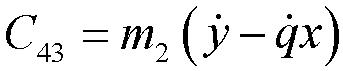


where m1 in the above formulas represents an equivalent mass of the robotic arm and palm of the robot; m2 represents the mass of the object; I1 represents a rotational inertia of the palm of the robot; and I2 represents a rotational inertia of the object. - Step 703: Obtain control information based on the sliding mechanical model, the control information including a motion trajectory of the carrying component and driving forces on the motion system in the process. For example, the driving forces are driving forces at various moments in the process.
- Optionally, the above control information can further include a motion trajectory of the robotic arm.
- In all embodiments of the present disclosure, the step of obtaining control information based on the sliding mechanical model includes:
- obtaining the control information based on a control constraint condition by minimizing a motion cost; the control constraint condition includes a sliding mechanical constraint condition represented by the sliding mechanical model; and the motion cost is at least one of motion time, a motion distance, or work of the carrying component in the following process: the carrying component is driven through the driving motor to move, so that the object slides on the upper surface of the carrying component with the movement of the carrying component under the actions of the friction and the gravity and slides away from the carrying component at the target position at the target speed.
- The motion time of the carrying component is time spent in the entire process of placing an object, which is a time difference between a moment when the carrying component starts to move and a moment when the object leaves the carrying component. The motion distance is a travel corresponding to a motion trajectory of the carrying component from the initial position to the target position where the object leaves the carrying component. The work is a product obtained by multiplying a force exerted by the carrying component from the initial position to the target position where the object leave the carrying component with the motion distance.
- The above minimization of the motion cost may include at least one of minimizing the execution time of the motion trajectory (namely, the time spent in the entire process of placing an object), minimizing the distance of the motion trajectory, and minimizing the work of the motion trajectory (namely, the work done by controlling a motor in the entire process of placing an object).
- In this embodiment, by taking at least one of the motion time, the motion distance, or the work as the motion cost and minimizing the motion cost, an optimal motion manner for the carrying component from the initial position to the target position where the object leaves the carrying component can be determined, and a control signal for the efficiency of placing an object can be obtained to control the driving motor and improve the control effect.
- In
step 702 above, the dynamical model in the sliding operation process is provided. The dynamical model of the sliding operation can be used for optimal control solution for operations of the robot operations. The dynamic sliding operation of the robot is as follows: In the motion process of the robot, a sliding acceleration and sliding speed of the object are changed by adjusting the inclination angle of the palm of the robot, and the object slides out at a specific speed. The object is placed dynamically, not statically, through the motion of the carrying component, which can cause actions of placing an object to be continuously performed, thereby improving the efficiency of placing an object. - In all embodiments of the present disclosure, the process that the object slides on the carrying component includes a first process of sliding away from the carrying component in a first direction relative to the carrying component.
- The control constraint condition includes:
- the sliding mechanical constraint condition: s. t. H(X)Ẍ + C(X,Ẋ)Ẋ + G(X) = F;
- a position constraint condition that the carrying component needs to satisfy at start time of the first process:X(0) = X 0; a position constraint condition that the carrying component needs to satisfy at end time of the first process: X(T) = XT ;
- a speed constraint condition that the object needs to satisfy at the start time of the first process: Ẋ(0) = Ẋ 0; and
- a speed constraint condition that the object needs to satisfy at the end time of the first process: X(T) = ẊT.
- A supporting force of the carrying component on the object is greater than or equal to 0: F 5 > 0.
where 0 and T represent time when the object starts to slide from the carrying component and time when the object slides out of the carrying component, respectively; X 0 and XT are positions that the object needs to reach at the time of starting the sliding and the time of sliding out; and Ẋ 0 and ẊT are speeds that the object needs to achieve at the time of starting the sliding and the time of sliding out, respectively. - According to the requirements of the sliding operation of the robot, the object needs to slide out of an edge at a certain speed at certain time from the initial position while the palm of the robot moves. By way of example, the motion cost includes the execution time of the motion trajectory. The following optimal trajectory generation equations can be listed according to task features:

- In the above formulas, X 0 and XT respectively provide a position of the object on the palm of the robot at sliding start time and a position of the object at final leave time; Ẋ 0 and ẊT respectively provide a speed of the object on the palm of the robot at the sliding start time and a speed of the object at the final leave time; F 5 ≥ 0 is mainly to ensure that there is always a contact between the object and the palm; and λ represents a weight coefficient of an acceleration optimization term for the robot.
- In the above optimal trajectory generation equations,

- According to the above formulas, the motion trajectory of the robot needs to meet its own motion trajectory requirements, and also needs to achieve the sliding of the object on the palm by changing the inclination angle.
- That is, in the embodiments of this application, it is necessary to calculate the motion trajectory and/or inclination angle of the palm of the robot (namely, the positions and poses of the palm at all moments) and then perform inverse kinematics calculation according to the positions and poses of the palm to obtain a joint trajectory of the robot.
- The above optimal control equation can be solved through an optimal control software package, such as PSOPT or Open Optimal Control Library (OpenOCL).
- In an optimal control stage of the above equation, an optimal trajectory X * and an optimal driving force F'* can be obtained.
- The above optimal driving force refers to a resultant force on the center of mass of the object and can be calculated according to an inertia force, a centrifugal force, and a gravity term of the object.
- In all embodiments of the present disclosure, the process of the object sliding on the carrying component includes:
a second process of sliding from an initial position relative to the carrying component in a second direction relative to the carrying component to a first position relative to the carrying component; and a third process of sliding away from the carrying component from the first position relative to the carrying component in a third direction relative to the carrying component. - The control constraint condition includes:
- the sliding mechanical model constraint condition: s. t. H(X)Ẍ + C(X, Ẋ)Ẋ + G(X) = F;
- a position constraint condition that the carrying component needs to satisfy at start time of the second process:X(0) = X 0; a position constraint condition that the carrying component needs to satisfy at start time of the third process:X(T 1) = X T
1 ; a position constraint condition that the carrying component needs to satisfy at end time of the third process: X(T 2) = X T2 ; - a speed constraint condition that the object needs to satisfy at the start time of the second process: Ẋ(0) = Ẋ 0; and
- a speed constraint condition that the object needs to satisfy at the start time of the third process: Ẋ(T 1) = Ẋ T
1 ; and - a speed constraint condition that the object needs to satisfy at the end time of the third process: Ẋ(T 2) = Ẋ T
2 . - A supporting force of the carrying component on the object is greater than or equal to 0: F 5 > 0.
where 0, T1, and T2 represent time when the object starts to slide from the carrying component, time when the object slides to the first position of the carrying component, and time when the object slides out of the carrying component, respectively; X 0, X T1 , and X T2 represent positions that the object needs to reach at the time when the object starts to slide from the carrying component, the time of reaching the first position, and the time of sliding out respectively; and Ẋ 0, Ẋ T1 , and Ẋ T2 represent speeds that the object needs to achieve at the time when the object starts to slide from the carrying component, the time of reaching the first position, and the time of sliding out respectively. - In all embodiments of the present disclosure, when the initial position of the object relative to the carrying component satisfies an adjustment condition, the process of the object sliding on the carrying component includes: a second process of sliding from an initial position relative to the carrying component in a second direction relative to the carrying component to a first position relative to the carrying component; and a third process of sliding away from the carrying component from the first position relative to the carrying component in a third direction relative to the carrying component. Due to division of different processes, the object placement process is controlled in stages, which can effectively improve the control precision of each process, thereby improving the accuracy in the object placement process and improving the efficiency of placing an object.
- In all embodiments of the present disclosure, the above adjustment condition includes: the initial position of the object relative to the carrying component is located at an edge of the carrying component.
- In some cases, the initial position of the object is not appropriate. For example, the object is located at the edge at the initial moment. At this time, the above solution cannot provide an effective sliding distance to allow the object to slide out of a contact surface at a certain initial speed. Therefore, it is necessary to use sliding to grasp the object to locate the object at a proper position. A schematic diagram of position adjustment and placement can be shown in
FIG. 9 . - The sliding operation shown in
FIG. 9 above includes two processes. One process is to adjust the position through the sliding operation, and the other process is to dynamically place the object through the sliding operation. - In this case, by way of example, the motion cost includes the execution time of the motion trajectory. The following optimal trajectory generation equations can be listed according to task features:

- In the above optimization model, T 1 represents sliding-based position adjustment time; T 2 - T 1 represents sliding-based dynamic placement time; and

- In the same way, for multi-stage optimal control, in an optimal control stage of the above equation, an optimal trajectory X* and an optimal driving force F * can be obtained.
- Step 704: Obtain a driving torque of the driving motor based on the control information.
- In all embodiments of the present disclosure, the controller obtains the control information through impedance control based on the sliding mechanical model. In the process of impedance control, a grasping force on the object is determined by the supporting force and friction of the carrying component on the object.
- An object impedance in robot operation refers to an impedance relation between the object and the robot due to external interaction of the object after the robot grasps the object. The object does not interact with another external environment, but the object needs to be in specific contact with the palm, and there is a dynamical equation of the object:

where Mb , Cb , and Nb respectively represent an inertial matrix, a centrifugal force term matrix, and a gravity term matrix of the object in a noninertial body coordinate system; Fb represents another external acting force on the object, which mainly refers to an equivalent operating force; Vb and V̇b refer to a motion speed and acceleration of the object; and R s,b represents a pose of the object. - In order to ensure an effective contact between the object and the palm and a smooth sliding operation, the equivalent operating force of the object and a grasping force of the palm need to satisfy the following relationship:


- where Fc represents the grasping force of the palm; G represents a grasping matrix; and F b* represents an expected equivalent operating force. The equivalent operating force of the object refers to a resultant force on the center of mass of the object, and the most direct influence factor of the equivalent operating force is a contact force (namely, the grasping force of the palm above) between the palm and the object. The above contact force is usually a three-dimensional (3D) vector, which contains a force vector and does not contain a torque vector. The vector of the equivalent operating force of the object is usually a six-dimensional (6D) vector, which contains both a force vector and a torque vector.
- Considering the dynamics of the robotic arm and an external force on the robotic arm, there is:

where Mr (θ), Cr (θ,θ̇), and Nr (θ) respectively represent an inertial matrix, a centrifugal force item matrix, and a gravity matrix which are related to the robot;
- Therefore, a control torque of the robotic arm is as follows:


where, u represents a control correction term related to a robot joint acceleration; kp and kd represent control coefficients; and JV represents a mapping jacobian matrix between the cartesian speed of the object and motion of a joint of the robot. - When the object is operated, it is necessary to control a cartesian pose of the robot. In actual control, an underlying controller of the robot needs to control all the joints of the robot, and controlling all the joints is achieved by a joint driving torque. Therefore, in the embodiments of this application, the controller of the robot needs to calculate a driving torque of the driving motor according to the above formulas.
- Step 705: Drive the carrying component to move through the driving motor based on the driving torque, so that the object, configured to slide on an upper surface of the carrying component with the movement of the carrying component under actions of friction and gravity, slides away from the carrying component.
- The motion that drives the carrying component includes at least one of situations of causing the carrying component to change a pose or to move. Exemplarily, causing the carrying component to change a pose includes causing the carrying component to rotate clockwise or counterclockwise, so that a carrying plane of the carrying component tilts. Exemplary, causing the carrying component to move includes causing the carrying component to move in any direction to reach another position (for example, the edge position of the tabletop for placing the object). Optionally, the movement in any direction may specifically be either movement along a straight line or movement along a curve.
- It can be seen based on the above content that in the embodiments of this application, in a case that the object slides on the upper surface of the carrying component, an acceleration of the object on the upper surface of the carrying component is controlled by an offset angle of the upper surface of the carrying component relative to a horizontal plane, and resistance to the object in the sliding process is a sliding friction.
- Specifically, in the sliding process of the object on the upper surface of the carrying component, as the inclination angle of the carrying component increases, the acceleration of the object on the upper surface of the carrying component is greater than 0. Afterwards, the object starts to slide in an accelerated manner. As the inclination angle of the carrying component changes, the acceleration of the object on the upper surface of the carrying component can continue to be greater than 0 (the sliding friction is less than a component of the gravity of the object on the upper surface of the carrying component, and in this case, the object continues to slide in the accelerated manner), or the acceleration of the object on the upper surface of the carrying component may be equal to 0 (the sliding friction is less than the component of the gravity of the object on the upper surface of the carrying component, and in this case, the sliding speed of the object remains unchanged), or the acceleration of the object on the upper surface of the carrying component may be less than 0 (the sliding friction is greater than the component of the gravity of the object on the upper surface of the carrying component, and in this case, the object starts to decelerate).
- In an exemplary solution, in the object placement process, the robot first controls the palm to tilt in a large angle to cause the object to slide in the accelerated manner and then reduces the inclination angle of the palm to cause the object to decelerate and leave the palm.
- In another exemplary solution, in the object placement process, the robot first controls the palm to tilt in a large angle to cause the object to slide in the accelerated manner and then reduces the inclination angle of the palm to cause the object to slide at a constant speed and then leave the palm.
- In another exemplary solution, in the object placement process, the robot may control the palm to tilt in a large angle to cause the object to slide in the accelerated manner and then cause the object to leave the palm in the acceleration process.
- Through the solutions shown in the embodiments of this application, the above dynamic object placement policy belongs to a dynamic operation of the robot, and main advantages include the following:
- 1) Dynamic placement can effectively improve the task completion efficiency and can complete a splicing action with other dynamic tasks.
- 2) Rapid placement of high-mass large-size objects can be effectively completed.
- 3) An additional loaded end effector cannot be used, and complex tasks can be completed using the palm of the robot or a pallet.
- In summary, in the solutions shown in the embodiments of this application, the sliding mechanical model configured to indicate the relationship between the generalized coordinates of the motion system and the driving force on the motion system in the process that the carrying component carries the object and moves is constructed by using the friction coefficient between the object on the carrying component and the carrying component; the motion trajectory of the carrying component is then obtained based on the sliding mechanical model; and the driving motor is controlled based on driving forces on the motion system in the process and the control information, so that the object slides away from the carrying component at the target position at the target speed, thereby completing the placement of the object. In the above process, the object is placed dynamically, not statically, through the motion of the carrying component, which can cause actions of placing an object to be continuously performed, thereby improving the efficiency of placing an object.
-
FIG. 10 is a structural block diagram of an apparatus for controlling a robotic arm provided according to an exemplary embodiment of this application. The robotic arm includes a carrying component, a robotic arm main body, and a driving motor, and the carrying component is connected to the robotic arm main body. The apparatus includes: - a
coefficient obtaining module 1001, configured to obtain a friction coefficient between an object on the carrying component and the carrying component; - a
model construction module 1002, configured to construct a sliding mechanical model based on the friction coefficient; the sliding mechanical model being configured to indicate a relationship between generalized coordinates of a motion system and a driving force on the motion system in a process that the carrying component carries the object and moves; the motion system including the carrying component and the object; - a control
information obtaining module 1003, configured to obtain control information based on the sliding mechanical model; the control information including a motion trajectory of the carrying component and driving forces on the motion system in the process; - a driving
control module 1004, configured to: drive the carrying component to move through the driving motor based on the control information, so that the object slides on an upper surface of the carrying component with the movement of the carrying component under actions of a friction and the gravity and slides away from the carrying component at a target position at a target speed. - In all embodiments of the present disclosure, in a case that the object slides on the upper surface of the carrying component, an acceleration of the object on the upper surface of the carrying component is controlled by an offset angle of the upper surface of the carrying component relative to a horizontal plane, and resistance to the object in the sliding process is a sliding friction.
- In all embodiments of the present disclosure, the control
information obtaining module 1003 is configured to obtain the control information based on a control constraint condition by minimizing a motion cost. The control constraint condition includes the sliding mechanical model; the motion cost is driving the carrying component to move through the driving motor based on the control information, so that the object slides on the upper surface of the carrying component with the movement of the carrying component under the actions of the friction and the gravity and slides away from the carrying component at the target position at the target speed. - In all embodiments of the present disclosure, the process that the object slides on the carrying component includes a first process of sliding away from the carrying component in a first direction relative to the carrying component.
- The control constraint condition includes:
- the sliding mechanical constraint condition;
- a position constraint condition that the carrying component needs to satisfy at start time of the first process and end time of the first process;
- a speed constraint condition that the object needs to satisfy at the start time of the first process; and
- a speed constraint condition that the object needs to satisfy at the end time of the first process; and
- a supporting force of the carrying component on the object is greater than or equal to 0.
- In all embodiments of the present disclosure, the process of the object sliding on the carrying component includes:
a second process of sliding from an initial position relative to the carrying component in a second direction relative to the carrying component to a first position relative to the carrying component; and a third process of sliding away from the carrying component from the first position relative to the carrying component in a third direction relative to the carrying component. - The control constraint condition includes:
- the sliding mechanical constraint condition;
- a position constraint condition that the carrying component needs to satisfy at start time of the second process, start time of the third process, and end time of the third process;
- a speed constraint condition that the object needs to satisfy at the start time of the second process; and
- a speed constraint condition that the object needs to satisfy at the start time of the third process; and
- a speed constraint condition that the object needs to satisfy at the end time of the third process; and
- a supporting force of the carrying component on the object is greater than or equal to 0.
- In all embodiments of the present disclosure, when the initial position of the object relative to the carrying component satisfies an adjustment condition, the process of the object sliding on the carrying component includes: a second process of sliding from an initial position relative to the carrying component in a second direction relative to the carrying component to a first position relative to the carrying component; and a third process of sliding away from the carrying component from the first position relative to the carrying component in a third direction relative to the carrying component.
- In all embodiments of the present disclosure, the adjustment condition includes: the initial position of the object relative to the carrying component is located at an edge of the carrying component.
- In all embodiments of the present disclosure, the control
information obtaining module 1003 is configured to obtains the control information through impedance control based on the sliding mechanical model; and
in the process of impedance control, a grasping force on the object is determined by the supporting force and friction of the carrying component on the object. - In all embodiments of the present disclosure, the
coefficient obtaining module 1001 is configured to: - obtain an image of the object sliding on the carrying component;
- obtain sliding information of the object based on the image of the object sliding on the carrying component; the sliding information including an inclination angle of the carrying component in a case that the object slides on the carrying component, and an acceleration of sliding of the object on the carrying component; and
- obtain the friction coefficient based on the sliding information.
- In summary, in the solutions shown in the embodiments of this application, the sliding mechanical model configured to indicate the relationship between the generalized coordinates of the motion system and the driving force on the motion system in the process that the carrying component carries the object and moves is constructed by using the friction coefficient between the object on the carrying component and the carrying component; the motion trajectory of the carrying component is then obtained based on the sliding mechanical model; and the driving motor is controlled based on driving forces on the motion system in the process and the control information, so that the object slides away from the carrying component at the target position at the target speed, thereby completing the placement of the object. In the above process, the object is placed dynamically, not statically, through the motion of the carrying component, which can cause actions of placing an object to be continuously performed, thereby improving the efficiency of placing an object.
- The apparatus provided in the foregoing embodiments is only illustrated by division of all the above functional modules. In practical application, the foregoing functions may be allocated to and completed by different functional modules as required, that is, an inner structure of a device is divided into different functional modules, so as to complete all or some of the functions described above. In addition, the apparatus provided in the foregoing embodiments and the method embodiments fall within the same conception. For details of a specific implementation process of the apparatus, refer to the method embodiments. Details are not described here again.
-
FIG. 11 is a structural block diagram of arobot 1100 provided according to an exemplary embodiment of this application. Therobot 1100 may include: a carryingcomponent 1101, a robotic armmain body 1102, a drivingmotor 1103, aprocessor 1104, and amemory 1105. - The
processor 1104 may include one or more processing cores, for example, a 4-core processor or an 8-core processor. Theprocessor 1104 may be implemented in at least one hardware form of a digital signal processor (DSP), a field-programmable gate array (FPGA), and a programmable logic array (PLA). In all embodiments of the present disclosure, theprocessor 1104 may further include an artificial intelligence (AI) processor. The AI processor is configured to process computing operations related to machine learning. - The
memory 1105 may include one or more computer-readable storage media. The computer-readable storage medium may be non-transitory. Thememory 1105 may further include a high-speed random access memory and a nonvolatile memory, for example, one or more disk storage devices or flash storage devices. In all embodiments of the present disclosure, the non-transitory computer-readable storage medium in thememory 1105 is configured to store at least one instruction, and the at least one instruction is used for being executed by theprocessor 1104 to implement the method for controlling the robotic arm provided in the method embodiments of this application. - In all embodiments of the present disclosure, the
robot 1100 optionally includes: a peripheral interface and at least one peripheral. Theprocessor 1104, thememory 1105, and the peripheral interface may be connected through a bus or a signal wire. Each peripheral may be connected to the peripheral interface through a bus, a signal wire, or a circuit board. Specifically, the peripherals may include: at least one of a radio frequency (RF) circuit, a display screen, a camera component, an audio circuit, and a power supply. - The peripheral interface may be configured to connect the at least one peripheral related to input/output (I/O) to the
processor 1104 and thememory 1105. - The camera component may be configured to capture images or videos.
- In all embodiments of the present disclosure, the
robot 1100 further includes one or more sensors. The one or more sensors include, but are not limited to: an acceleration sensor, a gyroscope sensor, a pressure sensor, an optical sensor, a proximity sensor, and the like. - A person skilled in the art may understand that the structure shown in
FIG. 11 constitutes no limitation on therobot 1100, and the robot may include more or fewer components than those shown in the figure, or some components may be combined, or a different component deployment may be used. - The embodiments of this application further provide a robot. The robot includes the robotic arm as shown in
FIG. 1 or FIG. 2 . The controller in the robotic arm may be configured to perform the method for controlling the robotic arm as shown inFIG. 3 orFIG. 7 . - The embodiments of this application further provide a computer-readable storage medium. The computer-readable storage medium stores at least one computer-readable instruction, and the at least one computer-readable instruction is loaded and executed by the one or more processors to implement the methods for controlling the robotic arm provided in all the above method embodiments.
- The embodiments of this application further provide a computer program product or a computer program. The computer program product or computer program includes computer-readable instructions which are stored in a computer-readable storage medium. One or more processors of a computer device (for example, a robot) reads the computer-readable instructions from the computer-readable storage medium, and the one or more processors execute the computer-readable instructions to cause the computer device to perform the method for controlling the robotic arm in any one of the embodiments.
- Optionally, the computer-readable storage medium may include: a read-only memory (ROM), a random access memory (RAM), a solid state drive (SSD), an optical disc, or the like. The RAM may include a resistance random access memory (ReRAM) and a dynamic random access memory (DRAM). The sequential numbers of the foregoing embodiments of this application are merely for description purpose but do not imply the preference of the embodiments.
- A person of ordinary skill in the art may understand that all or some of the steps of the foregoing embodiments may be implemented by hardware, or may be implemented by a program instructing relevant hardware. The program may be stored in a computer-readable storage medium. The storage medium mentioned above may be a ROM, a magnetic disk, an optical disc, or the like.
- The foregoing descriptions are merely optional embodiments of this application, but are not intended to limit this application. Any modification, equivalent replacement, or improvement made within the principle of this application shall fall within the protection scope of this application.
Claims (20)
- A robotic arm, the robotic arm comprising: a carrying component (110), a robotic arm main body (120), a driving motor (130), and a controller (140),the controller (140) being connected to the driving motor (130); the carrying component (110) being connected to the robotic arm main body (120); andthe controller (140) being configured to generate a control signal, the control signal controlling the driving motor (130) to drive the carrying component (110) to move, so that an object (150), configured to slide on an upper surface of the carrying component (110) with the movement of the carrying component (110) under actions of friction and gravity, slides away from the carrying component (110).
- The robotic arm according to claim 1, wherein the controller (140) is configured to generate a first movement control signal and a first rotation control signal;the first movement control signal controls the driving motor (130) to drive the carrying component (110) to move to a first position along a first direction;the first rotation control signal controls the driving motor (130) to drive the carrying component (110) to rotate to a first target pose being a downward sloping pose, so that the object (150) slides away from the carrying component (110) at a target position at a target speed.
- The robotic arm according to claim 1, wherein the controller (140) is configured to generate a second movement control signal and a second rotation control signal;the second movement control signal controls the driving motor (130) to drive the carrying component (110) to move to a second position along a second direction;the second rotation control signal controls the driving motor (130) to drive the carrying component (110) to rotate to a second target pose, being a tilting up pose, so that the object (150) slides away from the carrying component (110) at a target position at a target speed.
- The robotic arm according to claim 1, wherein the carrying component (110) is connected to the robotic arm main body (120) through a first joint (160);the driving motor (130) comprises a first driving motor (130a); andthe first driving motor (130a) is configured to drive the first joint (160) to rotate, so that the carrying component (110) rotates around the first joint (160).
- The robotic arm according to claim 1, wherein the driving motor (130) comprises a second driving motor (130b); and
the second driving motor (130b) is configured to drive the carrying component (110) to move. - The robotic arm according to claim 1, wherein the carrying component (110) is a component generating a friction with the object placed on the carrying component, and the carrying component (110) is a flat plate or a flat plate-like plate.
- The robotic arm according to any one of claims 1 to 6, wherein the robotic arm further comprises: an image acquisition assembly (170),the image acquisition assembly (170) being connected to the controller (140), andthe image acquisition assembly (170) being configured to acquire an image at the carrying component (110).
- A method for controlling a robotic arm, executable by a controller, the robotic arm comprising a carrying component, a robotic arm main body, and a driving motor, and the carrying component being connected to the robotic arm main body; the method comprising:obtaining a friction coefficient between an object on the carrying component and the carrying component;constructing a sliding mechanical model based on the friction coefficient; the sliding mechanical model being configured to indicate a relationship between generalized coordinates of a motion system and a driving force on the motion system in a process that the carrying component carries the object and moves; the motion system comprising the carrying component and the object;obtaining control information based on the sliding mechanical model; the control information comprising a motion trajectory of the carrying component and driving forces on the motion system in the process; anddriving the carrying component to move through the driving motor based on the control information, so that the object, configured to slide on an upper surface of the carrying component with the movement of the carrying component under actions of friction and gravity, slides away from the carrying component.
- The method according to claim 8, wherein in a case that the object slides on the upper surface of the carrying component, an acceleration of the object on the upper surface of the carrying component is controlled by an offset angle of the upper surface of the carrying component relative to a horizontal plane, and resistance to the object in the sliding process is sliding friction.
- The method according to claim 8 or 9, wherein the obtaining control information based on the sliding mechanical model comprises:obtaining the control information, based on a control constraint condition, by minimizing a motion cost; the control constraint condition comprises a sliding mechanical constraint condition represented by the sliding mechanical model; andthe motion cost is at least one of motion time, a motion distance, or work of the carrying component in the following process: the carrying component is driven through the driving motor to move, so that the object, configured to slide on the upper surface of the carrying component with the movement of the carrying component under the actions of the friction and the gravity, slides away from the carrying component at a target position at a target speed.
- The method according to claim 10, wherein the process that the object slides on the carrying component comprises a first process of sliding away from the carrying component in a first direction relative to the carrying component;
the control constraint condition comprises:the sliding mechanical constraint condition;a position constraint condition that the carrying component needs to satisfy at start time of the first process and end time of the first process;a speed constraint condition that the object needs to satisfy at the start time of the first process; anda speed constraint condition that the object needs to satisfy at the end time of the first process; anda supporting force of the carrying component on the object is greater than or equal to 0. - The method according to claim 10, wherein the process that the object slides on the carrying component comprises:a second process of sliding from an initial position relative to the carrying component in a second direction relative to the carrying component to a first position relative to the carrying component; and a third process of sliding away from the carrying component from the first position relative to the carrying component in a third direction relative to the carrying component;the control constraint condition comprises:the sliding mechanical constraint condition;a position constraint condition that the carrying component needs to satisfy at start time of the second process, start time of the third process, and end time of the third process;a speed constraint condition that the object needs to satisfy at the start time of the second process; anda speed constraint condition that the object needs to satisfy at the start time of the third process; anda speed constraint condition that the object needs to satisfy at the end time of the third process; anda supporting force of the carrying component on the object is greater than or equal to 0.
- The method according to claim 12, wherein in a case that the initial position of the object relative to the carrying component satisfies an adjustment condition,
the process that the object slides on the carrying component comprises: a second process of sliding from an initial position relative to the carrying component in a second direction relative to the carrying component to a first position relative to the carrying component; and a third process of sliding away from the carrying component from the first position relative to the carrying component in a third direction relative to the carrying component. - The method according to claim 13, wherein the adjustment condition comprises: the initial position of the object relative to the carrying component is located at an edge of the carrying component.
- The method according to claim 8 or 9, wherein the obtaining control information based on the sliding mechanical model comprises:obtaining the control information in an impedance control manner based on the sliding mechanical model; andin the process of impedance control, a grasping force on the object is determined by the supporting force and friction of the carrying component on the object.
- The method according to claim 8 or 9, wherein the obtaining a friction coefficient between an object on the carrying component and the carrying component comprises:obtaining images of the object sliding on the carrying component;obtaining sliding information of the object based on the images of the object sliding on the carrying component; the sliding information comprising an inclination angle of the carrying component in a case that the object slides on the carrying component, and an acceleration of sliding of the object on the carrying component; andobtaining the friction coefficient based on the sliding information.
- An apparatus for controlling a robotic arm, the robotic arm comprising a carrying component, a robotic arm main body, and a driving motor, and the carrying component being connected to the robotic arm main body; the apparatus comprising:a coefficient obtaining module, configured to obtain a friction coefficient between an object on the carrying component and the carrying component;a model construction module, configured to construct a sliding mechanical model based on the friction coefficient; the sliding mechanical model being configured to indicate a relationship between generalized coordinates of a motion system and a driving force on the motion system in a process that the carrying component carries the object and moves; the motion system comprising the carrying component and the object;a control information obtaining module, configured to obtain control information on the basis of the sliding mechanical model; the control information comprising a motion trajectory of the carrying component and driving forces on the motion system in the process; anda driving control module, configured to: drive the carrying component to move through the driving motor based on the control information, so that the object, configured to slide on an upper surface of the carrying component with the movement of the carrying component under actions of friction and gravity, slides away from the carrying component.
- A computer-readable storage medium, the storage medium storing at least one computer-readable instruction, and the at least one computer-readable instruction being loaded and executed by one or more processors to implement the method for controlling the robotic arm according to any one of claims 8 to 16.
- A computer program product, the computer program product comprising at least one computer-readable instruction, and the at least one computer-readable instruction being loaded and executed by one or more processors to implement the method for controlling the robotic arm according to any one of claims 8 to 16.
- A robot, the robot comprising the robotic arm according to any one of claims 1 to 7, and
the controller in the robotic arm being configured to perform the method for controlling the robotic arm according to any one of claims 8 to 16.
Applications Claiming Priority (2)
| Application Number | Priority Date | Filing Date | Title |
|---|---|---|---|
| CN202210107236.XA CN116551654B (en) | 2022-01-28 | 2022-01-28 | Robotic arm, control method and device of robotic arm, robot and storage medium |
| PCT/CN2022/138281 WO2023142724A1 (en) | 2022-01-28 | 2022-12-12 | Robotic arm, control method and apparatus for same, robot and storage medium |
Publications (2)
| Publication Number | Publication Date |
|---|---|
| EP4467293A1 true EP4467293A1 (en) | 2024-11-27 |
| EP4467293A4 EP4467293A4 (en) | 2025-07-16 |
Family
ID=87470353
Family Applications (1)
| Application Number | Title | Priority Date | Filing Date |
|---|---|---|---|
| EP22923513.0A Pending EP4467293A4 (en) | 2022-01-28 | 2022-12-12 | ROBOT ARM, CONTROL METHOD AND DEVICE THEREFOR, ROBOT AND STORAGE MEDIUM |
Country Status (4)
| Country | Link |
|---|---|
| US (1) | US20240009844A1 (en) |
| EP (1) | EP4467293A4 (en) |
| CN (1) | CN116551654B (en) |
| WO (1) | WO2023142724A1 (en) |
Families Citing this family (1)
| Publication number | Priority date | Publication date | Assignee | Title |
|---|---|---|---|---|
| CN119696415B (en) * | 2024-12-09 | 2025-10-10 | 中国航空工业集团公司北京长城计量测试技术研究所 | A control implementation method for high-precision six-dimensional posture adjustment with large payload |
Family Cites Families (15)
| Publication number | Priority date | Publication date | Assignee | Title |
|---|---|---|---|---|
| CN100534731C (en) * | 2007-05-11 | 2009-09-02 | 苏州艾隆科技有限公司 | Method for regularly placing box packed medicine |
| JP6042291B2 (en) * | 2013-08-27 | 2016-12-14 | 株式会社デンソーアイティーラボラトリ | Robot, robot control method, and robot control program |
| US9184084B2 (en) * | 2014-01-28 | 2015-11-10 | Lam Research Corporation | Wafer handling traction control system |
| CN205660724U (en) * | 2016-05-05 | 2016-10-26 | 佛山市新鹏机器人技术有限公司 | A constant force device for robot is terminal |
| US20190061154A1 (en) * | 2017-08-23 | 2019-02-28 | Tolomatic, Inc. | High speed linear actuator part placement system |
| CN107838924A (en) * | 2017-10-11 | 2018-03-27 | 深圳市贝优通新能源技术开发有限公司 | A kind of intelligent meal delivery robot for being easy to climb building and pass dish |
| CN207669311U (en) * | 2017-11-15 | 2018-07-31 | 南京昱晟机器人科技有限公司 | A kind of restaurant is with the automatic robot device that serves |
| CN108789441A (en) * | 2018-06-29 | 2018-11-13 | 郭莹莹 | meal delivery robot |
| CN109531620B (en) * | 2018-12-12 | 2021-09-07 | 北京洪泰智造工场运营管理有限公司 | An automatic robot arm |
| CN111618852B (en) * | 2019-05-09 | 2021-07-27 | 牧今科技 | Robot system with coordinated transfer mechanism |
| JP7705388B2 (en) * | 2019-11-01 | 2025-07-09 | ラム リサーチ コーポレーション | Wafer handling robot with gravity field sensor |
| JP7436197B2 (en) * | 2019-12-16 | 2024-02-21 | ファナック株式会社 | Goods conveyance system |
| JP7584857B2 (en) * | 2020-09-04 | 2024-11-18 | 川崎重工業株式会社 | Robot and workpiece transport method |
| CN112207794B (en) * | 2020-10-26 | 2021-08-03 | 北京洛必德科技有限公司 | Hotel meal delivery robot and working method thereof |
| JP2024518544A (en) * | 2021-05-14 | 2024-05-01 | ラム リサーチ コーポレーション | Blade-type end effector with angular compliance mechanism |
-
2022
- 2022-01-28 CN CN202210107236.XA patent/CN116551654B/en active Active
- 2022-12-12 WO PCT/CN2022/138281 patent/WO2023142724A1/en not_active Ceased
- 2022-12-12 EP EP22923513.0A patent/EP4467293A4/en active Pending
-
2023
- 2023-09-22 US US18/472,517 patent/US20240009844A1/en active Pending
Also Published As
| Publication number | Publication date |
|---|---|
| CN116551654A (en) | 2023-08-08 |
| CN116551654B (en) | 2025-02-25 |
| US20240009844A1 (en) | 2024-01-11 |
| EP4467293A4 (en) | 2025-07-16 |
| WO2023142724A1 (en) | 2023-08-03 |
Similar Documents
| Publication | Publication Date | Title |
|---|---|---|
| US10589424B2 (en) | Robot control device, robot, and robot system | |
| US9981381B1 (en) | Real time generation of phase synchronized trajectories | |
| US12138807B2 (en) | Robotic system to control multiple robots to perform a task cooperatively | |
| US12059814B2 (en) | Object-based robot control | |
| JP7825040B2 (en) | Controlling multiple robots for collaborative item pick-and-place | |
| US20230286161A1 (en) | Systems and Methods for Robotic Manipulation Using Extended Reality | |
| Staub et al. | The tele-magmas: An aerial-ground comanipulator system | |
| CN112703090B (en) | Robot control device, robot control method and storage medium | |
| US20220402127A9 (en) | Multi-angle end effector | |
| EP4467293A1 (en) | Robotic arm, control method and apparatus for same, robot and storage medium | |
| US12569991B2 (en) | Variable payload robot | |
| JP7841112B2 (en) | Control of a robotic manipulator for packing objects | |
| Kebritchi et al. | Design and development of an omnidirectional mobile manipulator for indoor environment | |
| US20230182298A1 (en) | Placement planning | |
| Bujnarowski et al. | Extension of Industrial and Collaborative Robots for Increased Work Space and Operation in Confined Spaces | |
| HK40091029A (en) | Mechanical arm, mechanical arm control method, apparatus, robot, and storage medium | |
| HK40091029B (en) | Mechanical arm, mechanical arm control method, apparatus, robot, and storage medium | |
| Wang et al. | Human-Robot Cooperative Manipulation Based on MPC and Whole-body Control | |
| WO2026052191A1 (en) | Manipulation of a workpiece using a robotic arm | |
| Bujnarowski et al. | and Operation in Confined Spaces | |
| Yang et al. | Operation of working plate with a 3D printed polymeric humanoid robot by ROS control system | |
| HK40088827B (en) | Method for robot to transport object and determining motion trajectory of robot to transport object | |
| HK40083850B (en) | Method for a robot to perform rotational motion on an object and robot | |
| HK40088827A (en) | Method for robot to transport object and determining motion trajectory of robot to transport object | |
| Berkemeier et al. | Development and enhancement of mobile robot arms for EOD applications |
Legal Events
| Date | Code | Title | Description |
|---|---|---|---|
| STAA | Information on the status of an ep patent application or granted ep patent |
Free format text: STATUS: THE INTERNATIONAL PUBLICATION HAS BEEN MADE |
|
| PUAI | Public reference made under article 153(3) epc to a published international application that has entered the european phase |
Free format text: ORIGINAL CODE: 0009012 |
|
| STAA | Information on the status of an ep patent application or granted ep patent |
Free format text: STATUS: REQUEST FOR EXAMINATION WAS MADE |
|
| 17P | Request for examination filed |
Effective date: 20240823 |
|
| AK | Designated contracting states |
Kind code of ref document: A1 Designated state(s): AL AT BE BG CH CY CZ DE DK EE ES FI FR GB GR HR HU IE IS IT LI LT LU LV MC ME MK MT NL NO PL PT RO RS SE SI SK SM TR |
|
| RIC1 | Information provided on ipc code assigned before grant |
Ipc: G01N 19/02 20060101ALN20250319BHEP Ipc: B25J 15/00 20060101ALI20250319BHEP Ipc: B25J 11/00 20060101ALI20250319BHEP Ipc: B25J 9/16 20060101AFI20250319BHEP |
|
| DAV | Request for validation of the european patent (deleted) | ||
| DAX | Request for extension of the european patent (deleted) | ||
| A4 | Supplementary search report drawn up and despatched |
Effective date: 20250616 |
|
| RIC1 | Information provided on ipc code assigned before grant |
Ipc: B25J 9/16 20060101AFI20250610BHEP Ipc: B25J 11/00 20060101ALI20250610BHEP Ipc: B25J 15/00 20060101ALI20250610BHEP Ipc: G01N 19/02 20060101ALN20250610BHEP |