EP4467266A1 - Predictive model for multi-laser powder bed fusion additive manufacturing - Google Patents
Predictive model for multi-laser powder bed fusion additive manufacturing Download PDFInfo
- Publication number
- EP4467266A1 EP4467266A1 EP24166059.6A EP24166059A EP4467266A1 EP 4467266 A1 EP4467266 A1 EP 4467266A1 EP 24166059 A EP24166059 A EP 24166059A EP 4467266 A1 EP4467266 A1 EP 4467266A1
- Authority
- EP
- European Patent Office
- Prior art keywords
- laser
- module
- build
- analysis tool
- additive manufacturing
- Prior art date
- Legal status (The legal status is an assumption and is not a legal conclusion. Google has not performed a legal analysis and makes no representation as to the accuracy of the status listed.)
- Pending
Links
Images


Classifications
-
- G—PHYSICS
- G05—CONTROLLING; REGULATING
- G05B—CONTROL OR REGULATING SYSTEMS IN GENERAL; FUNCTIONAL ELEMENTS OF SUCH SYSTEMS; MONITORING OR TESTING ARRANGEMENTS FOR SUCH SYSTEMS OR ELEMENTS
- G05B19/00—Program-control systems
- G05B19/02—Program-control systems electric
- G05B19/18—Numerical control [NC], i.e. automatically operating machines, in particular machine tools, e.g. in a manufacturing environment, so as to execute positioning, movement or co-ordinated operations by means of program data in numerical form
- G05B19/4097—Numerical control [NC], i.e. automatically operating machines, in particular machine tools, e.g. in a manufacturing environment, so as to execute positioning, movement or co-ordinated operations by means of program data in numerical form characterised by using design data to control NC machines, e.g. CAD/CAM
- G05B19/4099—Surface or curve machining, making three-dimensional [3D] objects, e.g. desktop manufacturing
-
- B—PERFORMING OPERATIONS; TRANSPORTING
- B22—CASTING; POWDER METALLURGY
- B22F—WORKING METALLIC POWDER; MANUFACTURE OF ARTICLES FROM METALLIC POWDER; MAKING METALLIC POWDER; APPARATUS OR DEVICES SPECIALLY ADAPTED FOR METALLIC POWDER
- B22F10/00—Additive manufacturing of workpieces or articles from metallic powder
- B22F10/80—Data acquisition or data processing
-
- B—PERFORMING OPERATIONS; TRANSPORTING
- B22—CASTING; POWDER METALLURGY
- B22F—WORKING METALLIC POWDER; MANUFACTURE OF ARTICLES FROM METALLIC POWDER; MAKING METALLIC POWDER; APPARATUS OR DEVICES SPECIALLY ADAPTED FOR METALLIC POWDER
- B22F10/00—Additive manufacturing of workpieces or articles from metallic powder
- B22F10/20—Direct sintering or melting
- B22F10/28—Powder bed fusion, e.g. selective laser melting [SLM] or electron beam melting [EBM]
-
- B—PERFORMING OPERATIONS; TRANSPORTING
- B22—CASTING; POWDER METALLURGY
- B22F—WORKING METALLIC POWDER; MANUFACTURE OF ARTICLES FROM METALLIC POWDER; MAKING METALLIC POWDER; APPARATUS OR DEVICES SPECIALLY ADAPTED FOR METALLIC POWDER
- B22F10/00—Additive manufacturing of workpieces or articles from metallic powder
- B22F10/80—Data acquisition or data processing
- B22F10/85—Data acquisition or data processing for controlling or regulating additive manufacturing processes
-
- B—PERFORMING OPERATIONS; TRANSPORTING
- B22—CASTING; POWDER METALLURGY
- B22F—WORKING METALLIC POWDER; MANUFACTURE OF ARTICLES FROM METALLIC POWDER; MAKING METALLIC POWDER; APPARATUS OR DEVICES SPECIALLY ADAPTED FOR METALLIC POWDER
- B22F12/00—Apparatus or devices specially adapted for additive manufacturing; Auxiliary means for additive manufacturing; Combinations of additive manufacturing apparatus or devices with other processing apparatus or devices
- B22F12/40—Radiation means
- B22F12/44—Radiation means characterised by the configuration of the radiation means
- B22F12/45—Two or more
-
- B—PERFORMING OPERATIONS; TRANSPORTING
- B29—WORKING OF PLASTICS; WORKING OF SUBSTANCES IN A PLASTIC STATE IN GENERAL
- B29C—SHAPING OR JOINING OF PLASTICS; SHAPING OF MATERIAL IN A PLASTIC STATE, NOT OTHERWISE PROVIDED FOR; AFTER-TREATMENT OF THE SHAPED PRODUCTS, e.g. REPAIRING
- B29C64/00—Additive manufacturing, i.e. manufacturing of three-dimensional [3D] objects by additive deposition, additive agglomeration or additive layering, e.g. by 3D printing, stereolithography or selective laser sintering
- B29C64/30—Auxiliary operations or equipment
- B29C64/386—Data acquisition or data processing for additive manufacturing
- B29C64/393—Data acquisition or data processing for additive manufacturing for controlling or regulating additive manufacturing processes
-
- B—PERFORMING OPERATIONS; TRANSPORTING
- B33—ADDITIVE MANUFACTURING TECHNOLOGY
- B33Y—ADDITIVE MANUFACTURING, i.e. MANUFACTURING OF THREE-DIMENSIONAL [3D] OBJECTS BY ADDITIVE DEPOSITION, ADDITIVE AGGLOMERATION OR ADDITIVE LAYERING, e.g. BY 3D PRINTING, STEREOLITHOGRAPHY OR SELECTIVE LASER SINTERING
- B33Y10/00—Processes of additive manufacturing
-
- B—PERFORMING OPERATIONS; TRANSPORTING
- B33—ADDITIVE MANUFACTURING TECHNOLOGY
- B33Y—ADDITIVE MANUFACTURING, i.e. MANUFACTURING OF THREE-DIMENSIONAL [3D] OBJECTS BY ADDITIVE DEPOSITION, ADDITIVE AGGLOMERATION OR ADDITIVE LAYERING, e.g. BY 3D PRINTING, STEREOLITHOGRAPHY OR SELECTIVE LASER SINTERING
- B33Y50/00—Data acquisition or data processing for additive manufacturing
-
- B—PERFORMING OPERATIONS; TRANSPORTING
- B33—ADDITIVE MANUFACTURING TECHNOLOGY
- B33Y—ADDITIVE MANUFACTURING, i.e. MANUFACTURING OF THREE-DIMENSIONAL [3D] OBJECTS BY ADDITIVE DEPOSITION, ADDITIVE AGGLOMERATION OR ADDITIVE LAYERING, e.g. BY 3D PRINTING, STEREOLITHOGRAPHY OR SELECTIVE LASER SINTERING
- B33Y50/00—Data acquisition or data processing for additive manufacturing
- B33Y50/02—Data acquisition or data processing for additive manufacturing for controlling or regulating additive manufacturing processes
-
- G—PHYSICS
- G06—COMPUTING OR CALCULATING; COUNTING
- G06F—ELECTRIC DIGITAL DATA PROCESSING
- G06F30/00—Computer-aided design [CAD]
- G06F30/20—Design optimisation, verification or simulation
-
- B—PERFORMING OPERATIONS; TRANSPORTING
- B22—CASTING; POWDER METALLURGY
- B22F—WORKING METALLIC POWDER; MANUFACTURE OF ARTICLES FROM METALLIC POWDER; MAKING METALLIC POWDER; APPARATUS OR DEVICES SPECIALLY ADAPTED FOR METALLIC POWDER
- B22F10/00—Additive manufacturing of workpieces or articles from metallic powder
- B22F10/30—Process control
- B22F10/36—Process control of energy beam parameters
-
- G—PHYSICS
- G05—CONTROLLING; REGULATING
- G05B—CONTROL OR REGULATING SYSTEMS IN GENERAL; FUNCTIONAL ELEMENTS OF SUCH SYSTEMS; MONITORING OR TESTING ARRANGEMENTS FOR SUCH SYSTEMS OR ELEMENTS
- G05B2219/00—Program-control systems
- G05B2219/30—Nc systems
- G05B2219/49—Nc machine tool, till multiple
- G05B2219/49023—3-D printing, layer of powder, add drops of binder in layer, new powder
-
- G—PHYSICS
- G06—COMPUTING OR CALCULATING; COUNTING
- G06F—ELECTRIC DIGITAL DATA PROCESSING
- G06F2113/00—Details relating to the application field
- G06F2113/10—Additive manufacturing, e.g. three-dimensional [3D] printing
-
- G—PHYSICS
- G06—COMPUTING OR CALCULATING; COUNTING
- G06F—ELECTRIC DIGITAL DATA PROCESSING
- G06F2119/00—Details relating to the type or aim of the analysis or the optimisation
- G06F2119/18—Manufacturability analysis or optimisation for manufacturability
Definitions
- the present disclosure relates generally to additive manufacturing, and more specifically to an analysis tool and process for predicting flaw formation in multi-laser additive manufacturing operations.
- Additive manufacturing is a process that is utilized to create components by applying sequential material layers, with each layer being applied to the previous material layer.
- multiple different parameters affect whether an end product created using the additive manufacturing process includes flaws or is within acceptable tolerances of a given part.
- components created using an additive manufacturing process are designed iteratively, by adjusting one or more parameters each iteration and examining the results to determine if the results have the required quality.
- Multi-laser additive manufacturing (AM) technology is a promising process to increase allowable part size and rate of production.
- multiple lasers in additive systems could add further complications and challenges to material quality.
- An example can be the teaching in US patent 10,252,512 which is incorporated by reference herein.
- an analysis tool for multi-laser additive manufacturing comprising a build file module; a preprocessor in operative communication with the build file module; a prime module in operative communication with the preprocessor; and a defect code module in operative communication with the prime module.
- a further embodiment of any of the foregoing embodiments may additionally and/or alternatively include the build file module includes a variety of build file inputs that relate to build files of an additive manufacturing machine and a part.
- a further embodiment of any of the foregoing embodiments may additionally and/or alternatively include build file inputs are selected from the group consisting of build conditions, primary process parameters, scan region for each laser, and a specimen STL or mesh file.
- a further embodiment of any of the foregoing embodiments may additionally and/or alternatively include the build conditions are selected from the group consisting of laser overlap, stripe width, angle and overlap, layer thickness, interlayer dwell time and powder particle size.
- a further embodiment of any of the foregoing embodiments may additionally and/or alternatively include the primary process parameters are selected from the group consisting of scan speed, laser power and spot size for each laser.
- a further embodiment of any of the foregoing embodiments may additionally and/or alternatively include the pre-processor includes code to extract process parameters and laser regions from a scan strategy build file in the build file module, and seamlessly pass this information to the defect code module for further defect analysis.
- a further embodiment of any of the foregoing embodiments may additionally and/or alternatively include the prime module is configured to determine a location, a size and a shape of stripes from input parameters which are validated against an actual multi-laser build file input.
- a further embodiment of any of the foregoing embodiments may additionally and/or alternatively include the defect code module is configured to produce outputs selected from the group consisting of a temperature map representing local temperature increase as a result of prior layers, stripes and hatching, laser thermal interaction; two dimension and three dimension defect maps representing a lack of fusion and keyhole porosities; and a time-location map representing the location of each laser during a build.
- the defect code module is configured to produce outputs selected from the group consisting of a temperature map representing local temperature increase as a result of prior layers, stripes and hatching, laser thermal interaction; two dimension and three dimension defect maps representing a lack of fusion and keyhole porosities; and a time-location map representing the location of each laser during a build.
- a further embodiment of any of the foregoing embodiments may additionally and/or alternatively include the defect code module is configured to generate a time-location map for lasers using inputs including scan speed, hatch distance and stripe angle.
- a further embodiment of any of the foregoing embodiments may additionally and/or alternatively include the defect code module is configured to employ a defect code to predict the location, size and shape of the stripes from input parameters, such as bounding boxes for each laser, a stripe width, angle and overlap, and a height of layer.
- the defect code module is configured to employ a defect code to predict the location, size and shape of the stripes from input parameters, such as bounding boxes for each laser, a stripe width, angle and overlap, and a height of layer.
- a further embodiment of any of the foregoing embodiments may additionally and/or alternatively include the analysis tool is configured to produce a preliminary quality metric as a function of a ratio between a number of points associated with defects and total number of points.
- a further embodiment of any of the foregoing embodiments may additionally and/or alternatively include the analysis tool is configured to employ a time search algorithm to locate lasers at any time.
- a process for employing an analysis tool for multi-laser additive manufacturing comprising configuring a build file module; operatively connecting a preprocessor with the build file module; operatively connecting a prime module with the preprocessor; and operatively connecting a defect code module with the prime module.
- Particular embodiments may further include at least one, or a plurality of, the following optional features. Each of these optional features may be added separate from other optional features, or in combination with other optional features.
- a further embodiment of any of the foregoing embodiments may additionally and/or alternatively include the further comprising configuring the prime module to determine a location, a size and a shape of stripes from input parameters which are validated against an actual multi-laser build file input.
- a further embodiment of any of the foregoing embodiments may additionally and/or alternatively include the process further comprising configuring the defect code module to locate lasers at any specific time during a build.
- a further embodiment of any of the foregoing embodiments may additionally and/or alternatively include the process further comprising configuring the defect code module to generate a time-location map for lasers using inputs including scan speed, hatch distance and stripe angle.
- a further embodiment of any of the foregoing embodiments may additionally and/or alternatively include the process further comprising configuring the defect code module to employ a defect code to predict the location, size and shape of the stripes from input parameters, such as bounding boxes for each laser, a stripe width, angle and overlap, and a height of layer.
- a further embodiment of any of the foregoing embodiments may additionally and/or alternatively include the process further comprising configuring the analysis tool to produce a preliminary quality metric as a function of a ratio between a number of points associated with defects and total number of points.
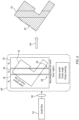
- FIG. 1 schematically illustrates an additive manufacturing machine 10, such as a laser powder bed fusion additive manufacturing (PBFAM) machine.
- the powder bed fusion machine can be an electron beam powder bed fusion machine.
- the exemplary additive manufacturing machine 10 includes a manufacturing chamber 12 with a platform 14 upon which a part 16 (alternatively referred to as a work piece) is additively manufactured.
- a controller 18 is connected to the chamber 12 and controls the additive manufacturing process according to any known additive manufacturing control system.
- controller 18 includes a processor 20 that receives and interprets input operations to define a sequence of the additive manufacturing.
- operations refers to instructions specifying operational conditions for one or more step in an additive manufacturing process.
- the controller 18 can, in some examples, include user interface devices such as a keyboard and view screen. In alternative examples, the controller 18 can include a wireless or wired communication apparatus for communicating with a remote user input device such as a PC.
- the controller 18 receives a desired additive manufacturing operation, or sequence of operations, and evaluates the entered operation(s) to determine if the resultant part 16 will be free of flaws.
- free of flaws, or flaw free refers to a part 16 or workpiece with no flaws causing the part or workpiece to fall outside of predefined flaw tolerance.
- the predefined tolerances can include an amount of unmelt, a surface roughness, or any other measurable property of the part 16.
- factors impacting the output parameters can include material properties, environmental conditions, laser power, laser speed, or any other factors. While described and illustrated herein as a component of a laser powder bed fusion additive manufacturing machine, the software configuration and operations can, in some examples, be embodied as a distinct software program independent of the additive manufacturing machine, or included within any other type of additive manufacturing machine.
- a build strategy is parsed and/or specifically prescribed scan vectors are used to create stripe and hatch definitions in each layer of the build.
- the additive build is simulated layer-by-layer.
- the output is a map in build parameter space (e.g. laser power, laser speed, layer thickness, etc.).
- the map is partitioned into different regions reflecting whether flaws are present: lack of fusion, keyholing, the flaw-free "good” zone, etc.
- a process map is optionally location-specific and dependent upon geometry. If the entirety of a part is in the "good" zone of the process map, it is predicted to be flaw-free.
- a technician can generate a part 16, or design a sequence of operations to generate a part 16, without requiring substantial empirical prototyping to be performed. This, in turn, allows the part to be designed faster, and with less expense, due to the substantially reduced number of physical iterations performed.
- the part 16 is shown as being created by a single laser and multiple lasers.
- the part 16 shown on the left side of Fig. 2 is laid down by use of a single laser 24.
- the whole part 16 is assigned to the single laser 24.
- the part 16 shown to the right side of Fig. 2 is assigned to multiple lasers 24.
- the multi-laser fusion is configured to increase the rate at which the part 16 can be built.
- the single laser fusion can have a different set of heat flux, interlayer dwell time, underlying temperature than the multi-laser fusion configuration.
- the part 16 can be divided into multiple regions 26, such as laser 1 region, laser 2 region and laser 3 region, as shown. Each region 26 can be processed by the different lasers 24. So, each region may have a different set of heat flux, interlayer dwell time, underlying temperature, and the like.
- the laser interaction zone 30 is caused by the two lasers operating simultaneous and contemporaneously adjacent along the laser interface 28 and creating a high thermal region 32 with higher temperature caused by the two lasers 24.
- the higher temperature profile in the high thermal region 32 can result in increased occurrence of defects 34, such as keyhole porosity as seen in Fig. 4 .
- the laser interaction zone 30 can be conducive to thermal deviation from acceptable temperature ranges for forming the part 16.
- the laser interaction zone 30 can include conditions that negatively impact one or more of the contemporaneous lasers 24 that results in deviation from normal laser application, intensity, location and the like. Spatter or other unwanted particle contamination can influence the quality of the laser 24 within the laser interaction zone 30.
- the build file module 52 provides input parameters 56 through a preprocessor 58 to a prime module 60.
- the pre-processor 58 includes code to extract key process parameters and laser regions/polygons from a scan strategy build file in the build file module 52, and seamlessly pass this information to the multi-laser defect code module 64 for further defect analysis.
- the preprocessor 58 processes the build files 52 to obtain key process parameters and bounding boxes for each laser region.
- the multi-laser defect code module 64 uses key process parameters and bounding boxes for each laser region 60 to determine location, size and shape of stripes 67, and to perform further defect analysis. Location, size and shape of stripes 67 predicted by defect code module 64 are validated against actual multi-laser build file inputs 54.
- a defect code module 64 generates a time-location map for lasers 24 using the inputs 54 provided by the user including scan speed, hatch distance and stripe angle. The user can also provide delay time for the lasers 24 if there is a lag between the lasers 24 to start a layer.
- the defect code module 64 can employ a multi-laser code which uses a global simulation domain rather than a local simulation domain used by the original defect code.
- the analysis tool 50 operates a multi-laser defect model 66 to produce the necessary output.
- the diagram shows the use of the build files module 52 for inputs to the preprocessor 58.
- the preprocessor 58 employes preprocessor code to supply the prime module 60.
- the defect code module 64 can arrange the layer layout from a standard triangle language (STL) file. Bounding boxes for each region 26 can be arranged as well as stripe width, stripe angle and stripe overlap.
- the defect code module 64 can employ a defect code to predict the location, size and shape of the stripes 67 from the input parameters, such as the bounding boxes for each laser, stripe width, angle and overlap, height of layer and the like).
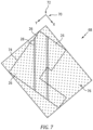
- the exemplary global simulation domain 68 can include a coordinate system 70 having axes 72 of the coordinate system 70 are aligned with the hatch vector and stripe edge. The edges of the simulation domain 68 are aligned with the coordinate system axes 72.
- the simulation domain 68 encompasses the entire layer 74.
- a structured grid of simulation points 76 are generated inside the domain 68 where temperature and defects are predicted.
- Masks are generated for each laser region 26 using the part STL file and the bounding boxes from the scan strategy file. These masks are used to identify the simulation points 76 which are located inside each laser region 26. Thermal analysis is performed for each laser region 26 and the results are mapped to the global simulation domain 68.
- the outcome results in single maps for temperature and defect as seen in Fig. 3 and Fig. 4 .
- the codes utilized in the analysis tool 50 can expand the effect of previous hatches, stripes and layers on temperature to multi-laser applications.
- the multi-laser process can produce higher temperatures which results in increased occurrence of keyhole porosity.
- the analysis tool 50 employs the model to predict the defects in the laser interaction zone 30.
- the analysis tool 50 can produce a preliminary quality metric as a function of a ratio between a number of points associated with the defects and total number of points.
- the analysis tool 50 can produce models for downskin portions of the part 16.
- the downskin region can be detected in the defect code module 64 based on predetermined Down Facing rules.
- Machine specific rules can be implemented in the analysis tool 50.
- Downskin hatch vectors can be parallel to inskin hatch vectors consistent with the scan strategy in the predetermined Down Facing rules.
- the analysis tool 50 can employ the defect model to calculate the effect of prior stripes on temperature and predict laser thermal interaction.
- the analysis tool 50 can employ equations which are developed to calculate the time and location used to predict the temperature increase from laser interaction.
- the analysis tool 50 can employ an efficient time search algorithm to locate the lasers 24 at any specific time.
- the analysis tool 50 can enforce the laser thermal interaction by manipulating laser timing and assigning different area sizes to each laser 24.
- the analysis tool 50 can employ the defect code module 64 to provide the option to use different process parameters for different lasers 24.
- the parameters include laser power, scan speed and spot size.
- the analysis tool 50 can predict the effect of location of laser interface 28 on the level of laser thermal interaction and therefore the sensitivity of defect formation to deviation from nominal parameters.
- a technical advantage of the disclosed analysis tool can include a system which helps engineers and designers understand and develop multi-laser PBFAM processes to increase rate of production and build large size parts.
- Another technical advantage of the disclosed analysis tool can include a fast acting analysis tool which can minimize the costly and time consuming trial and error practices which were used for qualifying additive manufactured parts.
- Another technical advantage of the disclosed analysis tool can include the information obtained from this predictive tool can be utilized to additively manufacture high quality parts which in turn minimizes post-build operations in the production process chain.
Landscapes
- Engineering & Computer Science (AREA)
- Materials Engineering (AREA)
- Chemical & Material Sciences (AREA)
- Manufacturing & Machinery (AREA)
- Physics & Mathematics (AREA)
- General Physics & Mathematics (AREA)
- Theoretical Computer Science (AREA)
- Health & Medical Sciences (AREA)
- General Health & Medical Sciences (AREA)
- Toxicology (AREA)
- Optics & Photonics (AREA)
- Mechanical Engineering (AREA)
- Human Computer Interaction (AREA)
- Automation & Control Theory (AREA)
- Computer Hardware Design (AREA)
- Evolutionary Computation (AREA)
- Geometry (AREA)
- General Engineering & Computer Science (AREA)
- Plasma & Fusion (AREA)
Abstract
An analysis tool for multi-laser additive manufacturing including a build file module; a preprocessor in operative communication with the build file module; a prime module in operative communication with the preprocessor; and a defect code module in operative communication with the prime module.
Description
- The present disclosure relates generally to additive manufacturing, and more specifically to an analysis tool and process for predicting flaw formation in multi-laser additive manufacturing operations.
- Additive manufacturing is a process that is utilized to create components by applying sequential material layers, with each layer being applied to the previous material layer. As a result of the iterative, trial and error, construction process, multiple different parameters affect whether an end product created using the additive manufacturing process includes flaws or is within acceptable tolerances of a given part. Typically, components created using an additive manufacturing process are designed iteratively, by adjusting one or more parameters each iteration and examining the results to determine if the results have the required quality.
- Multi-laser additive manufacturing (AM) technology is a promising process to increase allowable part size and rate of production. However, multiple lasers in additive systems could add further complications and challenges to material quality. There is no known tool to predict defect formation and dependency to process parameters for multi-laser applications. It is known how to predict defect type, density and location at the part level under a single laser operation. An example can be the teaching in
US patent 10,252,512 - What is needed is comprehensive analysis tool to study the effect of process parameters on formation of different types of defects in components produced by multi-laser powder bed fusion additive manufacturing (PBFAM).
- In accordance with the present disclosure, there is provided an analysis tool for multi-laser additive manufacturing comprising a build file module; a preprocessor in operative communication with the build file module; a prime module in operative communication with the preprocessor; and a defect code module in operative communication with the prime module.
- Particular embodiments may further include at least one, or a plurality of, the following optional features. Each of these optional features may be added separate from other optional features, or in combination with other optional features.
- A further embodiment of any of the foregoing embodiments may additionally and/or alternatively include the build file module includes a variety of build file inputs that relate to build files of an additive manufacturing machine and a part.
- A further embodiment of any of the foregoing embodiments may additionally and/or alternatively include build file inputs are selected from the group consisting of build conditions, primary process parameters, scan region for each laser, and a specimen STL or mesh file.
- A further embodiment of any of the foregoing embodiments may additionally and/or alternatively include the build conditions are selected from the group consisting of laser overlap, stripe width, angle and overlap, layer thickness, interlayer dwell time and powder particle size.
- A further embodiment of any of the foregoing embodiments may additionally and/or alternatively include the primary process parameters are selected from the group consisting of scan speed, laser power and spot size for each laser.
- A further embodiment of any of the foregoing embodiments may additionally and/or alternatively include the pre-processor includes code to extract process parameters and laser regions from a scan strategy build file in the build file module, and seamlessly pass this information to the defect code module for further defect analysis.
- A further embodiment of any of the foregoing embodiments may additionally and/or alternatively include the prime module is configured to determine a location, a size and a shape of stripes from input parameters which are validated against an actual multi-laser build file input.
- A further embodiment of any of the foregoing embodiments may additionally and/or alternatively include the defect code module is configured to produce outputs selected from the group consisting of a temperature map representing local temperature increase as a result of prior layers, stripes and hatching, laser thermal interaction; two dimension and three dimension defect maps representing a lack of fusion and keyhole porosities; and a time-location map representing the location of each laser during a build.
- A further embodiment of any of the foregoing embodiments may additionally and/or alternatively include the defect code module is configured to locate lasers at any specific time during a build.
- A further embodiment of any of the foregoing embodiments may additionally and/or alternatively include the defect code module is configured to generate a time-location map for lasers using inputs including scan speed, hatch distance and stripe angle.
- A further embodiment of any of the foregoing embodiments may additionally and/or alternatively include the defect code module is configured to employ a defect code to predict the location, size and shape of the stripes from input parameters, such as bounding boxes for each laser, a stripe width, angle and overlap, and a height of layer.
- A further embodiment of any of the foregoing embodiments may additionally and/or alternatively include the analysis tool is configured to produce a preliminary quality metric as a function of a ratio between a number of points associated with defects and total number of points.
- A further embodiment of any of the foregoing embodiments may additionally and/or alternatively include the analysis tool is configured to employ a time search algorithm to locate lasers at any time.
- In accordance with the present disclosure, there is provided a process for employing an analysis tool for multi-laser additive manufacturing comprising configuring a build file module; operatively connecting a preprocessor with the build file module; operatively connecting a prime module with the preprocessor; and operatively connecting a defect code module with the prime module.
- Particular embodiments may further include at least one, or a plurality of, the following optional features. Each of these optional features may be added separate from other optional features, or in combination with other optional features.
- A further embodiment of any of the foregoing embodiments may additionally and/or alternatively include the further comprising configuring the prime module to determine a location, a size and a shape of stripes from input parameters which are validated against an actual multi-laser build file input.
- A further embodiment of any of the foregoing embodiments may additionally and/or alternatively include the process further comprising configuring the defect code module to produce outputs selected from the group consisting of a temperature map representing local temperature increase as a result of prior layers, stripes and hatching, laser thermal interaction; two dimension and three dimension defect maps representing a lack of fusion and keyhole porosities; and a time-location map representing the location of each laser during a build.
- A further embodiment of any of the foregoing embodiments may additionally and/or alternatively include the process further comprising configuring the defect code module to locate lasers at any specific time during a build.
- A further embodiment of any of the foregoing embodiments may additionally and/or alternatively include the process further comprising configuring the defect code module to generate a time-location map for lasers using inputs including scan speed, hatch distance and stripe angle.
- A further embodiment of any of the foregoing embodiments may additionally and/or alternatively include the process further comprising configuring the defect code module to employ a defect code to predict the location, size and shape of the stripes from input parameters, such as bounding boxes for each laser, a stripe width, angle and overlap, and a height of layer.
- A further embodiment of any of the foregoing embodiments may additionally and/or alternatively include the process further comprising configuring the analysis tool to produce a preliminary quality metric as a function of a ratio between a number of points associated with defects and total number of points.
- Other details of the analysis tool are set forth in the following detailed description and the accompanying drawings wherein like reference numerals depict like elements.
-
Fig. 1 is a schematic representation of an exemplary additive manufacturing machine. -
Fig. 2 is a schematic representation of a part created by a single laser along side the part created by multiple lasers. -
Fig. 3 is a schematic representation of a temperature map for multi-laser applications. -
Fig. 4 is a schematic representation of a defect map for multi-laser applications. -
Fig. 5 is an analysis tool diagram. -
Fig. 6 is a schematic diagram of the process with the analysis tool. -
Fig. 7 is a schematic diagram of an exemplary global simulation domain. - Referring now to
Fig. 1 , schematically illustrates anadditive manufacturing machine 10, such as a laser powder bed fusion additive manufacturing (PBFAM) machine. In alternate examples, the powder bed fusion machine can be an electron beam powder bed fusion machine. The exemplaryadditive manufacturing machine 10 includes amanufacturing chamber 12 with aplatform 14 upon which a part 16 (alternatively referred to as a work piece) is additively manufactured. Acontroller 18 is connected to thechamber 12 and controls the additive manufacturing process according to any known additive manufacturing control system. - Included within the
controller 18 is aprocessor 20 that receives and interprets input operations to define a sequence of the additive manufacturing. As utilized herein "operations" refers to instructions specifying operational conditions for one or more step in an additive manufacturing process. Thecontroller 18 can, in some examples, include user interface devices such as a keyboard and view screen. In alternative examples, thecontroller 18 can include a wireless or wired communication apparatus for communicating with a remote user input device such as a PC. - Also included in the
controller 18 is amemory 22. In some examples, thecontroller 18 receives a desired additive manufacturing operation, or sequence of operations, and evaluates the entered operation(s) to determine if theresultant part 16 will be free of flaws. For the purposes of the instant disclosure, free of flaws, or flaw free, refers to apart 16 or workpiece with no flaws causing the part or workpiece to fall outside of predefined flaw tolerance. By way of example, the predefined tolerances can include an amount of unmelt, a surface roughness, or any other measurable property of thepart 16. By way of example, factors impacting the output parameters can include material properties, environmental conditions, laser power, laser speed, or any other factors. While described and illustrated herein as a component of a laser powder bed fusion additive manufacturing machine, the software configuration and operations can, in some examples, be embodied as a distinct software program independent of the additive manufacturing machine, or included within any other type of additive manufacturing machine. - A build strategy is parsed and/or specifically prescribed scan vectors are used to create stripe and hatch definitions in each layer of the build. The additive build is simulated layer-by-layer. The output is a map in build parameter space (e.g. laser power, laser speed, layer thickness, etc.). The map is partitioned into different regions reflecting whether flaws are present: lack of fusion, keyholing, the flaw-free "good" zone, etc. A process map is optionally location-specific and dependent upon geometry. If the entirety of a part is in the "good" zone of the process map, it is predicted to be flaw-free.
- By using the defined process map, a technician can generate a
part 16, or design a sequence of operations to generate apart 16, without requiring substantial empirical prototyping to be performed. This, in turn, allows the part to be designed faster, and with less expense, due to the substantially reduced number of physical iterations performed. - Referring also to
Fig. 2 , thepart 16 is shown as being created by a single laser and multiple lasers. Thepart 16 shown on the left side ofFig. 2 is laid down by use of asingle laser 24. Thewhole part 16 is assigned to thesingle laser 24. Thepart 16 shown to the right side ofFig. 2 is assigned tomultiple lasers 24. The multi-laser fusion is configured to increase the rate at which thepart 16 can be built. The single laser fusion can have a different set of heat flux, interlayer dwell time, underlying temperature than the multi-laser fusion configuration. - With multi-laser fusion processes the
part 16 can be divided intomultiple regions 26, such aslaser 1 region,laser 2 region andlaser 3 region, as shown. Eachregion 26 can be processed by thedifferent lasers 24. So, each region may have a different set of heat flux, interlayer dwell time, underlying temperature, and the like. - Referring also to
Fig. 3 and Fig. 4 showing model predictions for temperature and defect maps for multi-laser applications. The multi-laser arrangement will includelaser interface 28 along the common boundaries of theregions 26. It is possible to create alaser interaction zone 30 near theseinterfaces 28. Thelasers 24 can create conditions that cause interaction between the adjoininglasers 24. - As seen in
Fig. 3 thelaser interaction zone 30 is caused by the two lasers operating simultaneous and contemporaneously adjacent along thelaser interface 28 and creating a highthermal region 32 with higher temperature caused by the twolasers 24. The higher temperature profile in the highthermal region 32 can result in increased occurrence ofdefects 34, such as keyhole porosity as seen inFig. 4 . Thelaser interaction zone 30 can be conducive to thermal deviation from acceptable temperature ranges for forming thepart 16. Also thelaser interaction zone 30 can include conditions that negatively impact one or more of thecontemporaneous lasers 24 that results in deviation from normal laser application, intensity, location and the like. Spatter or other unwanted particle contamination can influence the quality of thelaser 24 within thelaser interaction zone 30. - Referring also to
Fig. 5 , anexemplary analysis tool 50 is shown. Theanalysis tool 50 includes abuild file module 52. Thebuild file module 52 includes a variety ofbuild file inputs 54 that relate to build files of theadditive manufacturing machine 10 and thepart 16. Theinputs 54 to themodule 52 can include (1) build conditions including laser overlap; stripe width; angle and overlap; layer thickness; interlayer dwell time and powder particle size; (2) primary process parameters including scan speed, laser power and spot size for each laser; (3) scan region for each laser; and (4) specimen STL or mesh file. In an exemplary embodiment, a user can providebuild file inputs 54 directly to the multi-laserdefect code module 64. - The
build file module 52 providesinput parameters 56 through apreprocessor 58 to aprime module 60. The pre-processor 58 includes code to extract key process parameters and laser regions/polygons from a scan strategy build file in thebuild file module 52, and seamlessly pass this information to the multi-laserdefect code module 64 for further defect analysis. - The
preprocessor 58 processes the build files 52 to obtain key process parameters and bounding boxes for each laser region. The multi-laserdefect code module 64 uses key process parameters and bounding boxes for eachlaser region 60 to determine location, size and shape ofstripes 67, and to perform further defect analysis. Location, size and shape ofstripes 67 predicted bydefect code module 64 are validated against actual multi-laserbuild file inputs 54. - The outputs from the
defect code module 64 can include (1) temperature map representing local temperature increase as a result of prior layers, stripes and hatching as well as laser thermal interaction; (2) 2D and 3D defect maps representing lack of fusion and keyhole porosities; (3) time-location map representing the location of eachlaser 24 during the build. The level of thermal interaction betweenlasers 24 can be significant if thelasers 24 work in proximity of each other. Thedefect code module 64 operates with an efficient time search algorithm configured to locate thelasers 24 at any specific time during the build. - A
defect code module 64 generates a time-location map forlasers 24 using theinputs 54 provided by the user including scan speed, hatch distance and stripe angle. The user can also provide delay time for thelasers 24 if there is a lag between thelasers 24 to start a layer. Thedefect code module 64 can employ a multi-laser code which uses a global simulation domain rather than a local simulation domain used by the original defect code. Theanalysis tool 50 operates amulti-laser defect model 66 to produce the necessary output. - Referring also to
Fig. 6 , theanalysis tool 50 process flow is shown. The diagram shows the use of thebuild files module 52 for inputs to thepreprocessor 58. Thepreprocessor 58 employes preprocessor code to supply theprime module 60. Thedefect code module 64 can arrange the layer layout from a standard triangle language (STL) file. Bounding boxes for eachregion 26 can be arranged as well as stripe width, stripe angle and stripe overlap. Thedefect code module 64 can employ a defect code to predict the location, size and shape of thestripes 67 from the input parameters, such as the bounding boxes for each laser, stripe width, angle and overlap, height of layer and the like). - Referring also to
Fig. 7 , an exemplaryglobal simulation domain 68 is shown. The exemplaryglobal simulation domain 68 can include a coordinatesystem 70 havingaxes 72 of the coordinatesystem 70 are aligned with the hatch vector and stripe edge. The edges of thesimulation domain 68 are aligned with the coordinate system axes 72. Thesimulation domain 68 encompasses theentire layer 74. A structured grid of simulation points 76 are generated inside thedomain 68 where temperature and defects are predicted. Masks are generated for eachlaser region 26 using the part STL file and the bounding boxes from the scan strategy file. These masks are used to identify the simulation points 76 which are located inside eachlaser region 26. Thermal analysis is performed for eachlaser region 26 and the results are mapped to theglobal simulation domain 68. - The outcome results in single maps for temperature and defect as seen in
Fig. 3 and Fig. 4 . The codes utilized in theanalysis tool 50 can expand the effect of previous hatches, stripes and layers on temperature to multi-laser applications. The multi-laser process can produce higher temperatures which results in increased occurrence of keyhole porosity. Theanalysis tool 50 employs the model to predict the defects in thelaser interaction zone 30. Theanalysis tool 50 can produce a preliminary quality metric as a function of a ratio between a number of points associated with the defects and total number of points. - The
analysis tool 50 can produce models for downskin portions of thepart 16. The downskin region can be detected in thedefect code module 64 based on predetermined Down Facing rules. Machine specific rules can be implemented in theanalysis tool 50. Downskin hatch vectors can be parallel to inskin hatch vectors consistent with the scan strategy in the predetermined Down Facing rules. - The
analysis tool 50 can employ the defect model to calculate the effect of prior stripes on temperature and predict laser thermal interaction. Theanalysis tool 50 can employ equations which are developed to calculate the time and location used to predict the temperature increase from laser interaction. Theanalysis tool 50 can employ an efficient time search algorithm to locate thelasers 24 at any specific time. Theanalysis tool 50 can enforce the laser thermal interaction by manipulating laser timing and assigning different area sizes to eachlaser 24. Theanalysis tool 50 can employ thedefect code module 64 to provide the option to use different process parameters fordifferent lasers 24. The parameters include laser power, scan speed and spot size. Theanalysis tool 50 can predict the effect of location oflaser interface 28 on the level of laser thermal interaction and therefore the sensitivity of defect formation to deviation from nominal parameters. - A technical advantage of the disclosed analysis tool can include a system which helps engineers and designers understand and develop multi-laser PBFAM processes to increase rate of production and build large size parts.
- Another technical advantage of the disclosed analysis tool can include a fast acting analysis tool which can minimize the costly and time consuming trial and error practices which were used for qualifying additive manufactured parts.
- Another technical advantage of the disclosed analysis tool can include the information obtained from this predictive tool can be utilized to additively manufacture high quality parts which in turn minimizes post-build operations in the production process chain.
- There has been provided an analysis tool. While the analysis tool has been described in the context of specific embodiments thereof, other unforeseen alternatives, modifications, and variations may become apparent to those skilled in the art having read the foregoing description. Accordingly, it is intended to embrace those alternatives, modifications, and variations which fall within the broad scope of the appended claims.
Claims (15)
- An analysis tool for multi-laser additive manufacturing comprising:a build file module;a preprocessor in operative communication with the build file module;a prime module in operative communication with the preprocessor; anda defect code module in operative communication with the prime module.
- The analysis tool for additive manufacturing according to claim 1,wherein the build file module includes a variety of build file inputs that relate to build files of an additive manufacturing machine and a part; and/orwherein particularly build file inputs are selected from the group consisting of build conditions, primary process parameters, scan region for each laser, and a specimen STL or mesh file.
- The analysis tool for additive manufacturing according to claim 2,wherein the build conditions are selected from the group consisting of laser overlap, stripe width, angle and overlap, layer thickness, interlayer dwell time and powder particle size; and/orwherein the primary process parameters are selected from the group consisting of scan speed, laser power and spot size for each laser.
- The analysis tool for additive manufacturing according to any of claims 1 to 3,wherein the pre-processor includes code to extract process parameters and laser regions from a scan strategy build file in the build file module, and seamlessly pass this information to the defect code module for further defect analysis; and/orwherein the prime module is configured to determine a location, a size and a shape of stripes from input parameters which are validated against an actual multi-laser build file input.
- The analysis tool for additive manufacturing according to claim 1,
wherein the defect code module is configured to produce outputs selected from the group consisting of a temperature map representing local temperature increase as a result of prior layers, stripes and hatching, laser thermal interaction; two dimension and three dimension defect maps representing a lack of fusion and keyhole porosities; and a time-location map representing the location of each laser during a build. - The analysis tool for additive manufacturing according to any of claims 1 to 5,wherein the defect code module is configured to locate lasers at any specific time during a build; and/orwherein the defect code module is configured to generate a time-location map for lasers using inputs including scan speed, hatch distance and stripe angle.
- The analysis tool for additive manufacturing according to any of claims 1 to 6,
wherein the defect code module is configured to employ a defect code to predict the location, size and shape of the stripes from input parameters, such as bounding boxes for each laser, a stripe width, angle and overlap, and a height of layer. - The analysis tool for additive manufacturing according to any of claims 1 to 7,wherein the analysis tool is configured to produce a preliminary quality metric as a function of a ratio between a number of points associated with defects and total number of points: and/orwherein the analysis tool is configured to employ a time search algorithm to locate lasers at any time.
- A process for employing an analysis tool for multi-laser additive manufacturing comprising:configuring a build file module;operatively connecting a preprocessor with the build file module;operatively connecting a prime module with the preprocessor; andoperatively connecting a defect code module with the prime module.
- The process of claim 9,
further comprising configuring the prime module to determine a location, a size and a shape of stripes from input parameters which are validated against an actual multi-laser build file input. - The process of claim 9 or 10,
further comprising configuring the defect code module to produce outputs selected from the group consisting of a temperature map representing local temperature increase as a result of prior layers, stripes and hatching, laser thermal interaction; two dimension and three dimension defect maps representing a lack of fusion and keyhole porosities; and a time-location map representing the location of each laser during a build. - The process of any of claims 9 to 11,
further comprising configuring the defect code module to locate lasers at any specific time during a build. - The process of any of claims 9 to 12,
further comprising configuring the defect code module to generate a time-location map for lasers using inputs including scan speed, hatch distance and stripe angle. - The process of any of claims 9 to 13,
further comprising configuring the defect code module to employ a defect code to predict the location, size and shape of the stripes from input parameters, such as bounding boxes for each laser, a stripe width, angle and overlap, and a height of layer. - The process of claim 14,
further comprising configuring the analysis tool to produce a preliminary quality metric as a function of a ratio between a number of points associated with defects and total number of points.
Applications Claiming Priority (1)
| Application Number | Priority Date | Filing Date | Title |
|---|---|---|---|
| US18/201,786 US20240393765A1 (en) | 2023-05-25 | 2023-05-25 | Predictive model for multi-laser powder bed fusion additive manufacturing |
Publications (1)
| Publication Number | Publication Date |
|---|---|
| EP4467266A1 true EP4467266A1 (en) | 2024-11-27 |
Family
ID=90482053
Family Applications (1)
| Application Number | Title | Priority Date | Filing Date |
|---|---|---|---|
| EP24166059.6A Pending EP4467266A1 (en) | 2023-05-25 | 2024-03-25 | Predictive model for multi-laser powder bed fusion additive manufacturing |
Country Status (2)
| Country | Link |
|---|---|
| US (1) | US20240393765A1 (en) |
| EP (1) | EP4467266A1 (en) |
Citations (1)
| Publication number | Priority date | Publication date | Assignee | Title |
|---|---|---|---|---|
| US10252512B2 (en) | 2016-04-12 | 2019-04-09 | United Technologies Corporation | System and process for evaluating and validating additive manufacturing operations |
-
2023
- 2023-05-25 US US18/201,786 patent/US20240393765A1/en active Pending
-
2024
- 2024-03-25 EP EP24166059.6A patent/EP4467266A1/en active Pending
Patent Citations (1)
| Publication number | Priority date | Publication date | Assignee | Title |
|---|---|---|---|---|
| US10252512B2 (en) | 2016-04-12 | 2019-04-09 | United Technologies Corporation | System and process for evaluating and validating additive manufacturing operations |
Non-Patent Citations (2)
| Title |
|---|
| BAYAT MOHAMAD ET AL: "A review of multi-scale and multi-physics simulations of metal additive manufacturing processes with focus on modeling strategies", ADDITIVE MANUFACTURING, ELSEVIER, NL, vol. 47, 2 September 2021 (2021-09-02), XP086891750, ISSN: 2214-8604, [retrieved on 20210902], DOI: 10.1016/J.ADDMA.2021.102278 * |
| MORAN T.P. ET AL: "Scan-by-scan part-scale thermal modelling for defect prediction in metal additive manufacturing", ADDITIVE MANUFACTURING, vol. 37, 23 October 2020 (2020-10-23), NL, pages 101667, XP093187865, ISSN: 2214-8604, Retrieved from the Internet <URL:https://pdf.sciencedirectassets.com/306190/1-s2.0-S2214860420X00066/1-s2.0-S2214860420310393/main.pdf?X-Amz-Security-Token=IQoJb3JpZ2luX2VjEFgaCXVzLWVhc3QtMSJGMEQCIExAT4245RR8JH5apPplBJWDda7y7drMnlOzOsb39MPzAiBMIrls5iqrX5bGIO0oL5m8xQKOavjne78h6Bm4PFyNxiqyBQgwEAUaDDA1OTAwMzU0Njg2NSIMUph8upDjOhEzqaImK> DOI: 10.1016/j.addma.2020.101667 * |
Also Published As
| Publication number | Publication date |
|---|---|
| US20240393765A1 (en) | 2024-11-28 |
Similar Documents
| Publication | Publication Date | Title |
|---|---|---|
| Paul et al. | Optimal part orientation in Rapid Manufacturing process for achieving geometric tolerances | |
| EP3232353B1 (en) | System and process for evaluating and validating additive manufacturing operations | |
| US10252512B2 (en) | System and process for evaluating and validating additive manufacturing operations | |
| EP3232351B1 (en) | System and process for evaluating and validating additive manufacturing operations | |
| US11609549B2 (en) | Transfer learning/dictionary generation and usage for tailored part parameter generation from coupon builds | |
| US11733678B2 (en) | Method for determining building instructions for an additive manufacturing method, method for generating a database with correction measures for controlling the process of an additive manufacturing method | |
| EP3203393B1 (en) | Preform fabrication system | |
| US20260084216A1 (en) | Uncertainty quantification or predictive defect model for multi-laser powder bed fusion additive manufacturing | |
| Lettori et al. | Geometrical characterization of circular multi-layered CMT WAAM specimens by 3D structured light scanning | |
| US20170057172A1 (en) | Tool Path Generator with Embedded Process Control Commands for Additive Manufacturing | |
| EP4467266A1 (en) | Predictive model for multi-laser powder bed fusion additive manufacturing | |
| Gao et al. | Feature-based energy consumption quantitation strategy for complex additive manufacturing parts | |
| EP4467265A1 (en) | Laser-plume interaction for predictive defect model for multi-laser powder bed fusion additive manufacturing | |
| US11766745B2 (en) | System and method of determining support locations for additively manufactured build parts | |
| US10252511B2 (en) | System and process for evaluating and validating additive manufacturing operations | |
| US10252510B2 (en) | System and process for evaluating and validating additive manufacturing operations | |
| EP4468193B1 (en) | Quality metric for predictive defect model for multi-laser powder bed fusion additive manufacturing | |
| US10252508B2 (en) | System and process for evaluating and validating additive manufacturing operations | |
| Palmer et al. | Development of a rapid prototyping system using response surface methodology | |
| RU2713678C2 (en) | Reinforced shape of target location in additively manufactured part and corresponding method | |
| US20180193917A1 (en) | Control system of additive manufacturing systems for controlling movement of sintering devices and related program products | |
| Rosen | Process control and metrics | |
| KR20230103386A (en) | Support generation method for atypical channel additive manufacturing using 3D printer |
Legal Events
| Date | Code | Title | Description |
|---|---|---|---|
| PUAI | Public reference made under article 153(3) epc to a published international application that has entered the european phase |
Free format text: ORIGINAL CODE: 0009012 |
|
| STAA | Information on the status of an ep patent application or granted ep patent |
Free format text: STATUS: THE APPLICATION HAS BEEN PUBLISHED |
|
| AK | Designated contracting states |
Kind code of ref document: A1 Designated state(s): AL AT BE BG CH CY CZ DE DK EE ES FI FR GB GR HR HU IE IS IT LI LT LU LV MC ME MK MT NL NO PL PT RO RS SE SI SK SM TR |
|
| STAA | Information on the status of an ep patent application or granted ep patent |
Free format text: STATUS: REQUEST FOR EXAMINATION WAS MADE |
|
| 17P | Request for examination filed |
Effective date: 20250523 |