EP4467206A1 - An apparatus for holding free weights for weightlifting exercises - Google Patents
An apparatus for holding free weights for weightlifting exercises Download PDFInfo
- Publication number
- EP4467206A1 EP4467206A1 EP23175807.9A EP23175807A EP4467206A1 EP 4467206 A1 EP4467206 A1 EP 4467206A1 EP 23175807 A EP23175807 A EP 23175807A EP 4467206 A1 EP4467206 A1 EP 4467206A1
- Authority
- EP
- European Patent Office
- Prior art keywords
- arm
- cradle
- rail
- weight
- held
- Prior art date
- Legal status (The legal status is an assumption and is not a legal conclusion. Google has not performed a legal analysis and makes no representation as to the accuracy of the status listed.)
- Granted
Links
Images


Classifications
-
- A—HUMAN NECESSITIES
- A63—SPORTS; GAMES; AMUSEMENTS
- A63B—APPARATUS FOR PHYSICAL TRAINING, GYMNASTICS, SWIMMING, CLIMBING, OR FENCING; BALL GAMES; TRAINING EQUIPMENT
- A63B21/00—Exercising apparatus for developing or strengthening the muscles or joints of the body by working against a counterforce, with or without measuring devices
- A63B21/06—User-manipulated weights
- A63B21/078—Devices for bench press exercises, e.g. supports, guiding means
- A63B21/0783—Safety features for bar-bells, e.g. drop limiting means
-
- A—HUMAN NECESSITIES
- A63—SPORTS; GAMES; AMUSEMENTS
- A63B—APPARATUS FOR PHYSICAL TRAINING, GYMNASTICS, SWIMMING, CLIMBING, OR FENCING; BALL GAMES; TRAINING EQUIPMENT
- A63B21/00—Exercising apparatus for developing or strengthening the muscles or joints of the body by working against a counterforce, with or without measuring devices
- A63B21/40—Interfaces with the user related to strength training; Details thereof
- A63B21/4027—Specific exercise interfaces
- A63B21/4029—Benches specifically adapted for exercising
-
- A—HUMAN NECESSITIES
- A63—SPORTS; GAMES; AMUSEMENTS
- A63B—APPARATUS FOR PHYSICAL TRAINING, GYMNASTICS, SWIMMING, CLIMBING, OR FENCING; BALL GAMES; TRAINING EQUIPMENT
- A63B21/00—Exercising apparatus for developing or strengthening the muscles or joints of the body by working against a counterforce, with or without measuring devices
- A63B21/40—Interfaces with the user related to strength training; Details thereof
- A63B21/4041—Interfaces with the user related to strength training; Details thereof characterised by the movements of the interface
- A63B21/4047—Pivoting movement
-
- A—HUMAN NECESSITIES
- A63—SPORTS; GAMES; AMUSEMENTS
- A63B—APPARATUS FOR PHYSICAL TRAINING, GYMNASTICS, SWIMMING, CLIMBING, OR FENCING; BALL GAMES; TRAINING EQUIPMENT
- A63B71/00—Games or sports accessories not covered in groups A63B1/00 - A63B69/00
- A63B71/0036—Accessories for stowing, putting away or transporting exercise apparatus or sports equipment
-
- A—HUMAN NECESSITIES
- A63—SPORTS; GAMES; AMUSEMENTS
- A63B—APPARATUS FOR PHYSICAL TRAINING, GYMNASTICS, SWIMMING, CLIMBING, OR FENCING; BALL GAMES; TRAINING EQUIPMENT
- A63B21/00—Exercising apparatus for developing or strengthening the muscles or joints of the body by working against a counterforce, with or without measuring devices
- A63B21/06—User-manipulated weights
- A63B21/072—Dumb-bells, bar-bells or the like, e.g. weight discs having an integral peripheral handle
- A63B21/0726—Dumb bells, i.e. with a central bar to be held by a single hand, and with weights at the ends
-
- A—HUMAN NECESSITIES
- A63—SPORTS; GAMES; AMUSEMENTS
- A63B—APPARATUS FOR PHYSICAL TRAINING, GYMNASTICS, SWIMMING, CLIMBING, OR FENCING; BALL GAMES; TRAINING EQUIPMENT
- A63B2220/00—Measuring of physical parameters relating to sporting activity
- A63B2220/10—Positions
- A63B2220/13—Relative positions
-
- A—HUMAN NECESSITIES
- A63—SPORTS; GAMES; AMUSEMENTS
- A63B—APPARATUS FOR PHYSICAL TRAINING, GYMNASTICS, SWIMMING, CLIMBING, OR FENCING; BALL GAMES; TRAINING EQUIPMENT
- A63B2220/00—Measuring of physical parameters relating to sporting activity
- A63B2220/50—Force related parameters
- A63B2220/51—Force
- A63B2220/52—Weight, e.g. weight distribution
-
- A—HUMAN NECESSITIES
- A63—SPORTS; GAMES; AMUSEMENTS
- A63B—APPARATUS FOR PHYSICAL TRAINING, GYMNASTICS, SWIMMING, CLIMBING, OR FENCING; BALL GAMES; TRAINING EQUIPMENT
- A63B2220/00—Measuring of physical parameters relating to sporting activity
- A63B2220/80—Special sensors, transducers or devices therefor
- A63B2220/801—Contact switches
-
- A—HUMAN NECESSITIES
- A63—SPORTS; GAMES; AMUSEMENTS
- A63B—APPARATUS FOR PHYSICAL TRAINING, GYMNASTICS, SWIMMING, CLIMBING, OR FENCING; BALL GAMES; TRAINING EQUIPMENT
- A63B2225/00—Miscellaneous features of sport apparatus, devices or equipment
- A63B2225/09—Adjustable dimensions
-
- A—HUMAN NECESSITIES
- A63—SPORTS; GAMES; AMUSEMENTS
- A63B—APPARATUS FOR PHYSICAL TRAINING, GYMNASTICS, SWIMMING, CLIMBING, OR FENCING; BALL GAMES; TRAINING EQUIPMENT
- A63B2225/00—Miscellaneous features of sport apparatus, devices or equipment
- A63B2225/09—Adjustable dimensions
- A63B2225/093—Height
-
- A—HUMAN NECESSITIES
- A63—SPORTS; GAMES; AMUSEMENTS
- A63B—APPARATUS FOR PHYSICAL TRAINING, GYMNASTICS, SWIMMING, CLIMBING, OR FENCING; BALL GAMES; TRAINING EQUIPMENT
- A63B24/00—Electric or electronic controls for exercising apparatus of preceding groups; Controlling or monitoring of exercises, sportive games, training or athletic performances
- A63B24/0087—Electric or electronic controls for exercising apparatus of groups A63B21/00 - A63B23/00, e.g. controlling load
Definitions
- inventive concepts described herein relate generally to apparatus for physical training. More particularly, embodiments of the present invention provide for a structure which may be used to aid athletes in the practice of lifting free weights, particularly dumbbells or the like.
- United States patent application publication number US2007099773A1 discloses an exercise equipment setup for spotting and temporarily storing dumbbells.
- the equipment includes a spotter mechanism having floor mount pedestals with vertical uprights extending upward from the floor pedestals, each vertical upright holding a spotter for holding and spotting a dumbbell when the dumbbell is to be used in a weightlifting exercise.
- the height of the spotter is adjustable along the length of the vertical upright.
- the spotter mechanism also includes a horizontal upright connected to the vertical uprights.
- the spotters can be slid along the horizontal upright to adjust the distance between two dumbbells in their respective spotters.
- Storage trays flanking the spotter mechanism are provided for storing the dumbbells when they are not being used as part of a weightlifting exercise.
- the weightlifter can therefore manually preposition the spotters so that dumbbells may be placed in a convenient position to be able to start an exercise, with the spotters being available to receive the dumbbells again should the weightlifter tire and require to replace
- a dumbbell rack is presented in German Utility Model publication number DE202014103356U1 , the rack having a dumbbell holder for storing a dumbbell, the holder being attached to a vertical support in such a way that the holder can be adjusted in height and rotated into any position suitable for exercising using a weight taken from the holder, the weight being presented to the weightlifter at an optimum position for beginning the exercise.
- a gear mechanism is provided to achieve the mentioned rotational function, where the dumbbell holder can be rotated into the optimal position for the exercise to commence.
- the gear mechanism can be operated by a foot pedal.
- the transmission ratio of the gear is given by the number of teeth on the bevel gear, allowing the weightlifter to conveniently rotate the dumbbell holder using their foot to place the weight in the correct position for performing the exercise and then to move the dumbbell holder away from the training area to allow for unhindered movement in the training area when performing the exercise.
- United States patent publication number US7001341 B1 discloses a weightlifting apparatus for supporting a pair of dumbbells.
- the apparatus includes side frames and elevation adjustment means on the side frames.
- dumbbell supports are respectively coupled to the elevation adjustment means on the first and second side frames for supporting a dumbbell in a plurality of different elevations.
- the apparatus includes a motor to allow a varied vertical adjustment of the dumbbell supports for different sized users or for different exercises, such as exercises performed with a weightlifting bench, or a seat, or standing.
- the apparatus includes at least one cradle biased toward an out-of-the-way position relative to the operating field of the user, preferably employing one or more gas springs to achieve the bias.
- the weight of the dumbbell disposed in the cradle overcomes the bias to maintain the cradle in a substantially horizontal attitude for presentation of the dumbbell to the user.
- the weight can be presented on a cradle to the weightlifter in an optimum position and the cradle automatically returns to an out-of-the-way position once the weightlifter takes charge of the weight, allowing the weightlifter to move unhindered throughout the exercise.
- provision is made for apparatus for holding a free weight at a chosen height and in a chosen orientation for presentation of said free weight to a weightlifter, the apparatus comprising a cradle for holding said free weight, said cradle being attached to a first end of an arm, the arm being slidably mountable, at a second end of the arm, to an elongate rail, the rail and the arm being mutually configured to allow the second end of the arm to be held on the rail at a selected height from a plurality of selectable heights.
- the arm is an articulated arm having a plurality of sections, the arm comprising one or more articulations linking the plurality of sections, configured to allow the cradle to be held in a presentation position when the second end of the arm is held on the rail at the selected height, the free weight thus being presented at the chosen height and chosen orientation when held in the cradle; and: the arm is a motorised arm, configured to control a movement of one or more of the articulations of the arm to cause the sections of the arm to move the cradle at least from the presentation position towards a park position, the park position being a position which causes the cradle to be held away from the presentation position to allow unhindered movement of the weightlifter.
- the free weight may be a barbell, with one end of the barbell being held in a first cradle and the other end of the barbell being held in a second cradle.
- the free weight is a dumbbell and the apparatus comprises a pair of elongate rails each having its respective arm and cradle, the apparatus being configured to hold a pair of dumbbells, one in each cradle.
- the arm comprises three articulations around which sections of the arm may pivot.
- the arm may be likened to a human arm having an upper arm section, a lower arm section and a hand, with the upper arm having an articulation allowing it to pivot, in several directions, around the body at the shoulder.
- Another articulation is the elbow, allowing the upper arm and lower arm to articulate.
- Another articulation is the wrist, allowing the hand to articulate around the end of the lower arm in several directions.
- the arm of the apparatus may have three sections and three articulations.
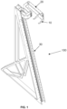
- Figure 1 shows an elongate rail and an articulated arm which may be deployed in an apparatus according to an embodiment of the present invention.
- One end of the articulated arm is attached to the elongate rail.
- the arm can be slid along the rail, so that when the rail is in an upright, or substantially vertical position, the height of the arm above a plane on which the rail stands can be adjusted.
- the other end of the arm carries a cradle which is designed to receive and hold a free weight.
- the elongate rail is configured to stand up on its own, preferably comprising a base which allows the elongate rail to stand up substantially vertically even when loaded with a weight on one end of the arm.
- two elongate rails are employed.
- further support is given to the apparatus by having a transversal, or substantially horizontal, spacing bar between two elongate bars.
- the elongate bars are configured to be attached to a weightlifting bench or a weightlifting chair or other such weightlifting station, thereby providing more stability to the apparatus.
- the apparatus may further comprise the bench or chair.
- the apparatus comprises two elongate rails and a weightlifting bench, with one elongate rail attached or otherwise secured to either side of the weightlifting bench. Still further support may be provided to such an apparatus by fixing a horizontal bar between the two elongate rails.
- Each of the elongate rails comprises a respective articulated arm with cradle for holding a weight.
- the arms may be secured at any from a selection of different heights along its respective elongate rail.
- An example of a securing means for fixing the arm at a chosen height is a simple pin through hole system, as shown in the accompanying drawings. Other, more sophisticated securing means are also possible according to different embodiments.
- an arm can be seen attached to each of the elongate rails.
- the height of the arm along the elongate rail can be chosen, for example by a holding pin pushed through the rail at one from a selection of predetermined locations along the rail.
- the arm is fixed to the rail at one end, while at the other end of the arm, a cradle is attached, the cradle being shaped to receive a free weight like a dumbbell or a barbell, for example.
- a dumbbell can be seen held in the cradle of one of the arms.
- Figures 3a and 3b show details of the arms.
- the arms have a plurality of sections and the sections have articulations between them.
- there may be three articulations a first one, called a shoulder articulation, located at or near where the end of the arm is attached to the rail, a second articulation, called an elbow articulation and a third articulation, called a wrist articulation.
- the first and second articulations have an upper arm section between them and the second and third articulations have a lower arm section between them.
- the wrist articulation holds the cradle and the cradle can pivot around the wrist articulation.
- One end of the upper arm section can pivot around the shoulder articulation and the other end can pivot around the elbow articulation.
- One end of the lower arm section can pivot around the elbow articulation and the other end can pivot around the wrist articulation. In this manner, it is possible for a weight, held in the cradle, to be positioned with great liberty in any orientation and at any point in space at different heights, depending on how high along the elongate rail the end of the arm is fixed.
- At least one of the articulations comprises a motor to engender relative rotation, under electronic control, between adjacent sections of the arm.
- each of the articulations comprises a motor.
- the motors are servomotors, configured to provide precisely controlled rotation under control of a processor or microcontroller.
- the motors may be stepper motors.
- the apparatus comprises a sensor configured to detect when the weightlifter has taken possession of the weight.
- a sensor configured to detect when the weightlifter has taken possession of the weight.
- control signals are sent to the motors to move the arms out of the way so that the weightlifter may continue with the weightlifting exercise unhindered by the apparatus.
- a sensor may be, for example, a weight sensor, configured to signal that the weight has been seized when the weightlifter has taken possession of, say, 90% of the weight of the free weight.
- the sensor may be a positional sensor, using a laser to detect when the weight has been raised a predetermined height above the presentation position.
- the weightlifter is free to manipulate or guide the arms at the required height on the rail until the various sections of the arms reach a position which places the weight in the optimal height and orientation for the weights to be conveniently seized by the weightlifter to begin the exercise.
- Such guiding or manipulation may be done either while the weight is held in its cradle or by first moving the arm and then placing the weight.
- the position where the weights can be conveniently seized by the weightlifter is known as the presentation position.
- the motors at the articulations of the arms cause the arms to be placed away from the weightlifter towards a park position.
- the servomotors may aid the weightlifter to manoeuvre the weights towards the presentation position.
- the presentation position and/or the park position may be programmable.
- the order of operation of each of the motors in the articulations may be programmed. For example, once it has been detected that the weightlifter has taken possession of the weight, a pre-determined sequence of movements of the different sections of the arms may ensue. This can be done by programming the order movement of each of the servomotors in the arms and the amount of angle through which each of the servomotors is entrained, depending on how the arms are intended to move.
- the motors at the wrists may first rotate the cradles away from the lifter, while the motors at the elbows and those at the shoulders may then contribute towards moving the fore-arms and upper arms of the arms away from the lifter, thus ensuring that the weightlifter is unhindered by the apparatus once he or she begins to carry out the weightlifting exercise.
- the motors are battery-powered.
- the mechanical design of the cradles, arms and rails are such that weights in excess of 100kg may be held in each cradle, while servomotors or stepper motors powered by batteries are strong enough to be able to move the arms and cradles away from the weightlifter once he or she has taken possession of the weight.
- embodiments of the present invention may operate with any weight that is generally used by weightlifting practitioners in many gyms, for example for weights ranging from around 1kg or so up to weights in excess of 100kg.
Landscapes
- Health & Medical Sciences (AREA)
- General Health & Medical Sciences (AREA)
- Physical Education & Sports Medicine (AREA)
- Life Sciences & Earth Sciences (AREA)
- Biophysics (AREA)
- Orthopedic Medicine & Surgery (AREA)
- Rehabilitation Tools (AREA)
Abstract
Description
- The inventive concepts described herein relate generally to apparatus for physical training. More particularly, embodiments of the present invention provide for a structure which may be used to aid athletes in the practice of lifting free weights, particularly dumbbells or the like.
- United States patent application publication number
US2007099773A1 discloses an exercise equipment setup for spotting and temporarily storing dumbbells. The equipment includes a spotter mechanism having floor mount pedestals with vertical uprights extending upward from the floor pedestals, each vertical upright holding a spotter for holding and spotting a dumbbell when the dumbbell is to be used in a weightlifting exercise. The height of the spotter is adjustable along the length of the vertical upright. The spotter mechanism also includes a horizontal upright connected to the vertical uprights. The spotters can be slid along the horizontal upright to adjust the distance between two dumbbells in their respective spotters. Storage trays flanking the spotter mechanism are provided for storing the dumbbells when they are not being used as part of a weightlifting exercise. The weightlifter can therefore manually preposition the spotters so that dumbbells may be placed in a convenient position to be able to start an exercise, with the spotters being available to receive the dumbbells again should the weightlifter tire and require to replace the dumbbells quickly. - A dumbbell rack is presented in German Utility Model publication number
DE202014103356U1 , the rack having a dumbbell holder for storing a dumbbell, the holder being attached to a vertical support in such a way that the holder can be adjusted in height and rotated into any position suitable for exercising using a weight taken from the holder, the weight being presented to the weightlifter at an optimum position for beginning the exercise. A gear mechanism is provided to achieve the mentioned rotational function, where the dumbbell holder can be rotated into the optimal position for the exercise to commence. The gear mechanism can be operated by a foot pedal. The transmission ratio of the gear is given by the number of teeth on the bevel gear, allowing the weightlifter to conveniently rotate the dumbbell holder using their foot to place the weight in the correct position for performing the exercise and then to move the dumbbell holder away from the training area to allow for unhindered movement in the training area when performing the exercise. - United States patent publication number
US7001341 B1 discloses a weightlifting apparatus for supporting a pair of dumbbells. The apparatus includes side frames and elevation adjustment means on the side frames. dumbbell supports are respectively coupled to the elevation adjustment means on the first and second side frames for supporting a dumbbell in a plurality of different elevations. In some embodiments, the apparatus includes a motor to allow a varied vertical adjustment of the dumbbell supports for different sized users or for different exercises, such as exercises performed with a weightlifting bench, or a seat, or standing. - An apparatus for mounting a dumbbell at a height in position for grasping at the commencement of an exercise routine without expending energy to lift the dumbbell to such height for commencement of the exercise routine is disclosed in United States patent application publication number
US5954619A . The apparatus includes at least one cradle biased toward an out-of-the-way position relative to the operating field of the user, preferably employing one or more gas springs to achieve the bias. The weight of the dumbbell disposed in the cradle overcomes the bias to maintain the cradle in a substantially horizontal attitude for presentation of the dumbbell to the user. Thus the weight can be presented on a cradle to the weightlifter in an optimum position and the cradle automatically returns to an out-of-the-way position once the weightlifter takes charge of the weight, allowing the weightlifter to move unhindered throughout the exercise. - In view of the prior art, there remains a need to provide equipment to support a free weight and to be able to readily and easily adjust the position in which the weight is held to make it convenient for a weightlifter of said weight to be able to take possession and/or control of the weight to begin performing an exercise with the weight. The equipment should further present the weight in a manner in which the weightlifter will not be hindered in their movements once they have taken possession and/or control of the weight to perform an exercise with the weight.
- According to an aspect, provision is made for apparatus for holding a free weight at a chosen height and in a chosen orientation for presentation of said free weight to a weightlifter, the apparatus comprising a cradle for holding said free weight, said cradle being attached to a first end of an arm, the arm being slidably mountable, at a second end of the arm, to an elongate rail, the rail and the arm being mutually configured to allow the second end of the arm to be held on the rail at a selected height from a plurality of selectable heights.
- Advantageously:
the arm is an articulated arm having a plurality of sections, the arm comprising one or more articulations linking the plurality of sections, configured to allow the cradle to be held in a presentation position when the second end of the arm is held on the rail at the selected height, the free weight thus being presented at the chosen height and chosen orientation when held in the cradle; and:
the arm is a motorised arm, configured to control a movement of one or more of the articulations of the arm to cause the sections of the arm to move the cradle at least from the presentation position towards a park position, the park position being a position which causes the cradle to be held away from the presentation position to allow unhindered movement of the weightlifter. - According to an embodiment, the free weight may be a barbell, with one end of the barbell being held in a first cradle and the other end of the barbell being held in a second cradle. According to a preferred embodiment, the free weight is a dumbbell and the apparatus comprises a pair of elongate rails each having its respective arm and cradle, the apparatus being configured to hold a pair of dumbbells, one in each cradle.
- According to a preferred embodiment, the arm comprises three articulations around which sections of the arm may pivot. The arm may be likened to a human arm having an upper arm section, a lower arm section and a hand, with the upper arm having an articulation allowing it to pivot, in several directions, around the body at the shoulder. Another articulation is the elbow, allowing the upper arm and lower arm to articulate. Another articulation is the wrist, allowing the hand to articulate around the end of the lower arm in several directions. Likewise, the arm of the apparatus may have three sections and three articulations.
- The inventive concepts described herein will be better understood thanks to the detailed description which follows and the accompanying drawings, which are given as non-limiting examples of embodiments of the inventive concepts described herein, namely:
-
FIG. 1 , showing an elongate rail and an articulated arm, which may be deployed in an apparatus according to an embodiment disclosed herein; -
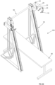
FIG. 2a , illustrating an embodiment of the invention described herein, the embodiment comprising a pair of elongate rails, the embodiment being shown with a dumbbell being held in one of the arms, where the embodiment is deployed around a weightlifting bench; -
FIG. 2b , illustrating another embodiment of the invention described herein, deployed about a weightlifting bench; and -
FIGs. 3a and 3b , showing detail of an arm and a cradle as deployed in embodiments disclosed herein, the arm and cradle being shown in a presentation position and in a parked position, respectively, in each of the figures. -
Figure 1 shows an elongate rail and an articulated arm which may be deployed in an apparatus according to an embodiment of the present invention. One end of the articulated arm is attached to the elongate rail. The arm can be slid along the rail, so that when the rail is in an upright, or substantially vertical position, the height of the arm above a plane on which the rail stands can be adjusted. The other end of the arm carries a cradle which is designed to receive and hold a free weight. - According to an embodiment, the elongate rail is configured to stand up on its own, preferably comprising a base which allows the elongate rail to stand up substantially vertically even when loaded with a weight on one end of the arm. In an embodiment of the apparatus described herein, two elongate rails are employed. According to an embodiment, which may be combined with any of the embodiments of elongate rails mentioned above, further support is given to the apparatus by having a transversal, or substantially horizontal, spacing bar between two elongate bars. According to another embodiment, the elongate bars are configured to be attached to a weightlifting bench or a weightlifting chair or other such weightlifting station, thereby providing more stability to the apparatus. The apparatus may further comprise the bench or chair.
- In a preferred embodiment of the apparatus, the apparatus comprises two elongate rails and a weightlifting bench, with one elongate rail attached or otherwise secured to either side of the weightlifting bench. Still further support may be provided to such an apparatus by fixing a horizontal bar between the two elongate rails. Each of the elongate rails comprises a respective articulated arm with cradle for holding a weight. The arms may be secured at any from a selection of different heights along its respective elongate rail. An example of a securing means for fixing the arm at a chosen height is a simple pin through hole system, as shown in the accompanying drawings. Other, more sophisticated securing means are also possible according to different embodiments.
- In
figures 1 ,2a and2b , an arm can be seen attached to each of the elongate rails. The height of the arm along the elongate rail can be chosen, for example by a holding pin pushed through the rail at one from a selection of predetermined locations along the rail. The arm is fixed to the rail at one end, while at the other end of the arm, a cradle is attached, the cradle being shaped to receive a free weight like a dumbbell or a barbell, for example. Infigure 2a , a dumbbell can be seen held in the cradle of one of the arms. -
Figures 3a and 3b show details of the arms. The arms have a plurality of sections and the sections have articulations between them. According to an embodiment, there may be three articulations, a first one, called a shoulder articulation, located at or near where the end of the arm is attached to the rail, a second articulation, called an elbow articulation and a third articulation, called a wrist articulation. The first and second articulations have an upper arm section between them and the second and third articulations have a lower arm section between them. The wrist articulation holds the cradle and the cradle can pivot around the wrist articulation. One end of the upper arm section can pivot around the shoulder articulation and the other end can pivot around the elbow articulation. One end of the lower arm section can pivot around the elbow articulation and the other end can pivot around the wrist articulation. In this manner, it is possible for a weight, held in the cradle, to be positioned with great liberty in any orientation and at any point in space at different heights, depending on how high along the elongate rail the end of the arm is fixed. - According to an embodiment, at least one of the articulations comprises a motor to engender relative rotation, under electronic control, between adjacent sections of the arm. According to a preferred embodiment, each of the articulations comprises a motor.
- According to an embodiment, the motors are servomotors, configured to provide precisely controlled rotation under control of a processor or microcontroller. According to another embodiment, the motors may be stepper motors.
- According to an embodiment, the apparatus comprises a sensor configured to detect when the weightlifter has taken possession of the weight. When the sensor detects that the weight has been lifted, or has begun to be lifted, from the cradle, control signals are sent to the motors to move the arms out of the way so that the weightlifter may continue with the weightlifting exercise unhindered by the apparatus. Such a sensor may be, for example, a weight sensor, configured to signal that the weight has been seized when the weightlifter has taken possession of, say, 90% of the weight of the free weight. In another embodiment, the sensor may be a positional sensor, using a laser to detect when the weight has been raised a predetermined height above the presentation position.
- According to an embodiment, the weightlifter is free to manipulate or guide the arms at the required height on the rail until the various sections of the arms reach a position which places the weight in the optimal height and orientation for the weights to be conveniently seized by the weightlifter to begin the exercise. Such guiding or manipulation may be done either while the weight is held in its cradle or by first moving the arm and then placing the weight. The position where the weights can be conveniently seized by the weightlifter is known as the presentation position. Once the weights have been seized by the weightlifter, the motors at the articulations of the arms cause the arms to be placed away from the weightlifter towards a park position. In embodiments where servomotors are used, the servomotors may aid the weightlifter to manoeuvre the weights towards the presentation position. In some embodiments the presentation position and/or the park position may be programmable. In order to ensure an orderly movement of the arms from the presentation position to the park position, the order of operation of each of the motors in the articulations may be programmed. For example, once it has been detected that the weightlifter has taken possession of the weight, a pre-determined sequence of movements of the different sections of the arms may ensue. This can be done by programming the order movement of each of the servomotors in the arms and the amount of angle through which each of the servomotors is entrained, depending on how the arms are intended to move. For example, the motors at the wrists may first rotate the cradles away from the lifter, while the motors at the elbows and those at the shoulders may then contribute towards moving the fore-arms and upper arms of the arms away from the lifter, thus ensuring that the weightlifter is unhindered by the apparatus once he or she begins to carry out the weightlifting exercise.
- In a preferred embodiment, the motors are battery-powered. The mechanical design of the cradles, arms and rails are such that weights in excess of 100kg may be held in each cradle, while servomotors or stepper motors powered by batteries are strong enough to be able to move the arms and cradles away from the weightlifter once he or she has taken possession of the weight. Thus, embodiments of the present invention may operate with any weight that is generally used by weightlifting practitioners in many gyms, for example for weights ranging from around 1kg or so up to weights in excess of 100kg.
Claims (12)
- An apparatus for holding a free weight at a chosen height and in a chosen orientation for presentation of said free weight to a weightlifter, the apparatus comprising a cradle for holding said free weight, said cradle being attached to a first end of an arm, the arm being slidably mountable, at a second end of the arm, to an elongate rail, the rail and the arm being mutually configured to allow the second end of the arm to be held on the rail at a selected height from a plurality of selectable heights;
the apparatus characterised in that:
the arm is an articulated arm having a plurality of sections, the arm comprising one or more articulations linking the plurality of sections, configured to allow the cradle to be held in a presentation position when the second end of the arm is held on the rail at the selected height, the free weight thus being presented at the chosen height and chosen orientation when held in the cradle; and in that:
the arm is a motorised arm, configured to control a movement of one or more of the articulations of the arm to cause the sections of the arm to move the cradle at least from the presentation position towards a park position, the park position being a position which causes the cradle to be held away from the presentation position to allow unhindered movement of the weightlifter. - The apparatus according to claim 1, the apparatus comprising: a pair of arms each having a cradle to hold a respective one from a pair of free weights; and a pair of elongate rails upon each of which a respective one from the pair of arms may be held.
- The apparatus according to either of claims 1 or 2, wherein at least one of the elongate rails is configured to be free-standing, with the length of the rail being in a substantially vertical direction.
- The apparatus according to any of claims 2 to 4, further comprising a horizontal support bar between the two elongate rails.
- The apparatus according to any of the preceding claims, wherein at least one elongate rail is configured to be attached to a part of a bench or seat.
- The apparatus according to any of the preceding claims, wherein said free weight is a dumbbell or said free weights are dumbbells or said free weight is a barbell.
- The apparatus according to any of the preceding claims, further comprising a sensor, the sensor being configured to detect when the weightlifter has taken possession of the weight and consequently to trigger the movement of the cradles towards the park position.
- The apparatus according to any of the preceding claims, wherein at least one of the motors is a servomotor.
- The apparatus according to any of the preceding claims, wherein at least one of the motors is a stepper motor.
- The apparatus according to any of the preceding claims, further comprising one or more processors for programming a controlled movement of the cradles towards the park position and/or towards the presentation position.
- The apparatus according to any of the preceding claims, the apparatus comprising three or more articulations in each arm.
- The apparatus according to any of the preceding claims, wherein the apparatus is battery operated for providing power to the motors and the processors.
Priority Applications (2)
| Application Number | Priority Date | Filing Date | Title |
|---|---|---|---|
| EP23175807.9A EP4467206B1 (en) | 2023-05-26 | 2023-05-26 | An apparatus for holding free weights for weightlifting exercises |
| PCT/IB2024/055143 WO2024246732A1 (en) | 2023-05-26 | 2024-05-27 | An apparatus for holding free weights for weightlifting exercises |
Applications Claiming Priority (1)
| Application Number | Priority Date | Filing Date | Title |
|---|---|---|---|
| EP23175807.9A EP4467206B1 (en) | 2023-05-26 | 2023-05-26 | An apparatus for holding free weights for weightlifting exercises |
Publications (3)
| Publication Number | Publication Date |
|---|---|
| EP4467206A1 true EP4467206A1 (en) | 2024-11-27 |
| EP4467206C0 EP4467206C0 (en) | 2025-12-10 |
| EP4467206B1 EP4467206B1 (en) | 2025-12-10 |
Family
ID=86605641
Family Applications (1)
| Application Number | Title | Priority Date | Filing Date |
|---|---|---|---|
| EP23175807.9A Active EP4467206B1 (en) | 2023-05-26 | 2023-05-26 | An apparatus for holding free weights for weightlifting exercises |
Country Status (2)
| Country | Link |
|---|---|
| EP (1) | EP4467206B1 (en) |
| WO (1) | WO2024246732A1 (en) |
Citations (10)
| Publication number | Priority date | Publication date | Assignee | Title |
|---|---|---|---|---|
| US5472397A (en) * | 1994-07-21 | 1995-12-05 | Ammoscato; Vincenzo | Retractable dumbbell support bench |
| US5509876A (en) * | 1994-12-02 | 1996-04-23 | Reyes; Gilbert | Weight-bar support structure with retractable arms |
| US5954619A (en) | 1998-02-24 | 1999-09-21 | Petrone; Charles M. | Apparatus for storage and presentation of exercise dumbbells |
| US7001341B2 (en) | 2003-08-13 | 2006-02-21 | Scimed Life Systems, Inc. | Marking biopsy sites |
| US20070099773A1 (en) | 2005-11-03 | 2007-05-03 | Dumbbell Spotter, Llc | Spotter for use with dumbbell weights |
| US20080070759A1 (en) * | 2006-04-21 | 2008-03-20 | Chaulk Mark E | Dumbbell Supporting Device |
| DE202014103356U1 (en) | 2014-07-22 | 2014-08-04 | Thomas Rafael Gil | Dumbbell rack for dumbbells |
| EP2939718A1 (en) * | 2014-04-29 | 2015-11-04 | Piotr Gluchowski | Device to prevent injuries |
| US20180290001A1 (en) * | 2015-10-15 | 2018-10-11 | Jun Young BAEK | Electric exercise assistance device |
| US11406862B2 (en) * | 2019-02-14 | 2022-08-09 | Downing Family, LLC | Systems for supporting dumbbell and barbell |
-
2023
- 2023-05-26 EP EP23175807.9A patent/EP4467206B1/en active Active
-
2024
- 2024-05-27 WO PCT/IB2024/055143 patent/WO2024246732A1/en not_active Ceased
Patent Citations (10)
| Publication number | Priority date | Publication date | Assignee | Title |
|---|---|---|---|---|
| US5472397A (en) * | 1994-07-21 | 1995-12-05 | Ammoscato; Vincenzo | Retractable dumbbell support bench |
| US5509876A (en) * | 1994-12-02 | 1996-04-23 | Reyes; Gilbert | Weight-bar support structure with retractable arms |
| US5954619A (en) | 1998-02-24 | 1999-09-21 | Petrone; Charles M. | Apparatus for storage and presentation of exercise dumbbells |
| US7001341B2 (en) | 2003-08-13 | 2006-02-21 | Scimed Life Systems, Inc. | Marking biopsy sites |
| US20070099773A1 (en) | 2005-11-03 | 2007-05-03 | Dumbbell Spotter, Llc | Spotter for use with dumbbell weights |
| US20080070759A1 (en) * | 2006-04-21 | 2008-03-20 | Chaulk Mark E | Dumbbell Supporting Device |
| EP2939718A1 (en) * | 2014-04-29 | 2015-11-04 | Piotr Gluchowski | Device to prevent injuries |
| DE202014103356U1 (en) | 2014-07-22 | 2014-08-04 | Thomas Rafael Gil | Dumbbell rack for dumbbells |
| US20180290001A1 (en) * | 2015-10-15 | 2018-10-11 | Jun Young BAEK | Electric exercise assistance device |
| US11406862B2 (en) * | 2019-02-14 | 2022-08-09 | Downing Family, LLC | Systems for supporting dumbbell and barbell |
Also Published As
| Publication number | Publication date |
|---|---|
| EP4467206C0 (en) | 2025-12-10 |
| WO2024246732A1 (en) | 2024-12-05 |
| EP4467206B1 (en) | 2025-12-10 |
Similar Documents
| Publication | Publication Date | Title |
|---|---|---|
| EP0209563B1 (en) | Physical exercisers | |
| US4826157A (en) | Physical exercising apparatus | |
| US8740760B2 (en) | Pivoting twin arm support for free weights | |
| US10675502B2 (en) | Multi-functional exercise device | |
| US4934693A (en) | Multi-exercise free weight apparatus | |
| EP2731683B1 (en) | Exercise machine for providing weight lifting exercises similar to those provided by a free weight barbell | |
| US7575538B1 (en) | Compact multi-function exercise apparatus | |
| EP4267262B1 (en) | Exercise apparatus with integrated bench assembly | |
| WO1993004738A1 (en) | Training apparatus | |
| US9199111B2 (en) | Exercise apparatus | |
| US10814163B2 (en) | Exercise apparatus and method | |
| US4302009A (en) | Automatic lift off weight rack for barbells | |
| WO2007056094A2 (en) | Spotter for use with dumbbell weights | |
| US7001314B1 (en) | Dumbbell spotter | |
| US20070049472A1 (en) | Spotter for use with dumbbell weights | |
| US20080070759A1 (en) | Dumbbell Supporting Device | |
| US4974839A (en) | Multi-functional adjustable weight lifting & exercise apparatus | |
| US11077332B2 (en) | Fitness weight support | |
| GB2065482A (en) | Exercising bench | |
| US5449335A (en) | Waist-trimming exercise apparatus | |
| EP4467206B1 (en) | An apparatus for holding free weights for weightlifting exercises | |
| AU2022234382B2 (en) | Motor powered lifting rack system | |
| US8708869B2 (en) | Dynamic resistance training machine | |
| US6361481B1 (en) | Weight lifting simulator | |
| US20050164852A1 (en) | Muscle exercise device |
Legal Events
| Date | Code | Title | Description |
|---|---|---|---|
| PUAI | Public reference made under article 153(3) epc to a published international application that has entered the european phase |
Free format text: ORIGINAL CODE: 0009012 |
|
| STAA | Information on the status of an ep patent application or granted ep patent |
Free format text: STATUS: THE APPLICATION HAS BEEN PUBLISHED |
|
| AK | Designated contracting states |
Kind code of ref document: A1 Designated state(s): AL AT BE BG CH CY CZ DE DK EE ES FI FR GB GR HR HU IE IS IT LI LT LU LV MC ME MK MT NL NO PL PT RO RS SE SI SK SM TR |
|
| STAA | Information on the status of an ep patent application or granted ep patent |
Free format text: STATUS: REQUEST FOR EXAMINATION WAS MADE |
|
| 17P | Request for examination filed |
Effective date: 20250502 |
|
| GRAP | Despatch of communication of intention to grant a patent |
Free format text: ORIGINAL CODE: EPIDOSNIGR1 |
|
| STAA | Information on the status of an ep patent application or granted ep patent |
Free format text: STATUS: GRANT OF PATENT IS INTENDED |
|
| RIC1 | Information provided on ipc code assigned before grant |
Ipc: A63B 21/078 20060101AFI20250613BHEP Ipc: A63B 21/072 20060101ALN20250613BHEP |
|
| INTG | Intention to grant announced |
Effective date: 20250701 |
|
| RIC1 | Information provided on ipc code assigned before grant |
Ipc: A63B 21/078 20060101AFI20250623BHEP Ipc: A63B 21/072 20060101ALN20250623BHEP |
|
| GRAS | Grant fee paid |
Free format text: ORIGINAL CODE: EPIDOSNIGR3 |
|
| GRAA | (expected) grant |
Free format text: ORIGINAL CODE: 0009210 |
|
| STAA | Information on the status of an ep patent application or granted ep patent |
Free format text: STATUS: THE PATENT HAS BEEN GRANTED |
|
| AK | Designated contracting states |
Kind code of ref document: B1 Designated state(s): AL AT BE BG CH CY CZ DE DK EE ES FI FR GB GR HR HU IE IS IT LI LT LU LV MC ME MK MT NL NO PL PT RO RS SE SI SK SM TR |
|
| REG | Reference to a national code |
Ref country code: CH Ref legal event code: F10 Free format text: ST27 STATUS EVENT CODE: U-0-0-F10-F00 (AS PROVIDED BY THE NATIONAL OFFICE) Effective date: 20251210 Ref country code: GB Ref legal event code: FG4D |
|
| REG | Reference to a national code |
Ref country code: DE Ref legal event code: R096 Ref document number: 602023009453 Country of ref document: DE |
|
| REG | Reference to a national code |
Ref country code: IE Ref legal event code: FG4D |
|
| U01 | Request for unitary effect filed |
Effective date: 20251210 |
|
| U07 | Unitary effect registered |
Designated state(s): AT BE BG DE DK EE FI FR IT LT LU LV MT NL PT RO SE SI Effective date: 20251216 |
|
| REG | Reference to a national code |
Ref country code: CH Ref legal event code: R17 Free format text: ST27 STATUS EVENT CODE: U-0-0-R10-R17 (AS PROVIDED BY THE NATIONAL OFFICE) Effective date: 20260127 |
|
| PG25 | Lapsed in a contracting state [announced via postgrant information from national office to epo] |
Ref country code: ES Free format text: LAPSE BECAUSE OF FAILURE TO SUBMIT A TRANSLATION OF THE DESCRIPTION OR TO PAY THE FEE WITHIN THE PRESCRIBED TIME-LIMIT Effective date: 20251210 |
|
| PG25 | Lapsed in a contracting state [announced via postgrant information from national office to epo] |
Ref country code: NO Free format text: LAPSE BECAUSE OF FAILURE TO SUBMIT A TRANSLATION OF THE DESCRIPTION OR TO PAY THE FEE WITHIN THE PRESCRIBED TIME-LIMIT Effective date: 20260310 |
|
| PG25 | Lapsed in a contracting state [announced via postgrant information from national office to epo] |
Ref country code: HR Free format text: LAPSE BECAUSE OF FAILURE TO SUBMIT A TRANSLATION OF THE DESCRIPTION OR TO PAY THE FEE WITHIN THE PRESCRIBED TIME-LIMIT Effective date: 20251210 |
|
| PG25 | Lapsed in a contracting state [announced via postgrant information from national office to epo] |
Ref country code: RS Free format text: LAPSE BECAUSE OF FAILURE TO SUBMIT A TRANSLATION OF THE DESCRIPTION OR TO PAY THE FEE WITHIN THE PRESCRIBED TIME-LIMIT Effective date: 20260310 |
|
| REG | Reference to a national code |
Ref country code: CH Ref legal event code: U11 Free format text: ST27 STATUS EVENT CODE: U-0-0-U10-U11 (AS PROVIDED BY THE NATIONAL OFFICE) Effective date: 20260601 |
|
| U20 | Renewal fee for the european patent with unitary effect paid |
Year of fee payment: 4 Effective date: 20260511 |
|
| PG25 | Lapsed in a contracting state [announced via postgrant information from national office to epo] |
Ref country code: SM Free format text: LAPSE BECAUSE OF FAILURE TO SUBMIT A TRANSLATION OF THE DESCRIPTION OR TO PAY THE FEE WITHIN THE PRESCRIBED TIME-LIMIT Effective date: 20251210 |
|
| PG25 | Lapsed in a contracting state [announced via postgrant information from national office to epo] |
Ref country code: PL Free format text: LAPSE BECAUSE OF FAILURE TO SUBMIT A TRANSLATION OF THE DESCRIPTION OR TO PAY THE FEE WITHIN THE PRESCRIBED TIME-LIMIT Effective date: 20251210 |
|
| PGFP | Annual fee paid to national office [announced via postgrant information from national office to epo] |
Ref country code: CH Payment date: 20260601 Year of fee payment: 4 |
|
| PG25 | Lapsed in a contracting state [announced via postgrant information from national office to epo] |
Ref country code: IS Free format text: LAPSE BECAUSE OF FAILURE TO SUBMIT A TRANSLATION OF THE DESCRIPTION OR TO PAY THE FEE WITHIN THE PRESCRIBED TIME-LIMIT Effective date: 20260410 |
|
| PG25 | Lapsed in a contracting state [announced via postgrant information from national office to epo] |
Ref country code: CZ Free format text: LAPSE BECAUSE OF FAILURE TO SUBMIT A TRANSLATION OF THE DESCRIPTION OR TO PAY THE FEE WITHIN THE PRESCRIBED TIME-LIMIT Effective date: 20251210 |
|
| PG25 | Lapsed in a contracting state [announced via postgrant information from national office to epo] |
Ref country code: SK Free format text: LAPSE BECAUSE OF FAILURE TO SUBMIT A TRANSLATION OF THE DESCRIPTION OR TO PAY THE FEE WITHIN THE PRESCRIBED TIME-LIMIT Effective date: 20251210 |