EP4467174A2 - Component positioning of a linear shuttle pump - Google Patents
Component positioning of a linear shuttle pump Download PDFInfo
- Publication number
- EP4467174A2 EP4467174A2 EP24205751.1A EP24205751A EP4467174A2 EP 4467174 A2 EP4467174 A2 EP 4467174A2 EP 24205751 A EP24205751 A EP 24205751A EP 4467174 A2 EP4467174 A2 EP 4467174A2
- Authority
- EP
- European Patent Office
- Prior art keywords
- detent
- piston
- pump
- contact
- grip
- Prior art date
- Legal status (The legal status is an assumption and is not a legal conclusion. Google has not performed a legal analysis and makes no representation as to the accuracy of the status listed.)
- Pending
Links
Images






Classifications
-
- A—HUMAN NECESSITIES
- A61—MEDICAL OR VETERINARY SCIENCE; HYGIENE
- A61M—DEVICES FOR INTRODUCING MEDIA INTO, OR ONTO, THE BODY; DEVICES FOR TRANSDUCING BODY MEDIA OR FOR TAKING MEDIA FROM THE BODY; DEVICES FOR PRODUCING OR ENDING SLEEP OR STUPOR
- A61M5/00—Devices for bringing media into the body in a subcutaneous, intra-vascular or intramuscular way; Accessories therefor, e.g. filling or cleaning devices, arm-rests
- A61M5/14—Infusion devices, e.g. infusing by gravity; Blood infusion; Accessories therefor
- A61M5/142—Pressure infusion, e.g. using pumps
- A61M5/145—Pressure infusion, e.g. using pumps using pressurised reservoirs, e.g. pressurised by means of pistons
- A61M5/1452—Pressure infusion, e.g. using pumps using pressurised reservoirs, e.g. pressurised by means of pistons pressurised by means of pistons
- A61M5/1454—Pressure infusion, e.g. using pumps using pressurised reservoirs, e.g. pressurised by means of pistons pressurised by means of pistons spring-actuated, e.g. by a clockwork
-
- A—HUMAN NECESSITIES
- A61—MEDICAL OR VETERINARY SCIENCE; HYGIENE
- A61M—DEVICES FOR INTRODUCING MEDIA INTO, OR ONTO, THE BODY; DEVICES FOR TRANSDUCING BODY MEDIA OR FOR TAKING MEDIA FROM THE BODY; DEVICES FOR PRODUCING OR ENDING SLEEP OR STUPOR
- A61M5/00—Devices for bringing media into the body in a subcutaneous, intra-vascular or intramuscular way; Accessories therefor, e.g. filling or cleaning devices, arm-rests
- A61M5/14—Infusion devices, e.g. infusing by gravity; Blood infusion; Accessories therefor
- A61M5/142—Pressure infusion, e.g. using pumps
- A61M5/14212—Pumping with an aspiration and an expulsion action
- A61M5/14216—Reciprocating piston type
-
- A—HUMAN NECESSITIES
- A61—MEDICAL OR VETERINARY SCIENCE; HYGIENE
- A61M—DEVICES FOR INTRODUCING MEDIA INTO, OR ONTO, THE BODY; DEVICES FOR TRANSDUCING BODY MEDIA OR FOR TAKING MEDIA FROM THE BODY; DEVICES FOR PRODUCING OR ENDING SLEEP OR STUPOR
- A61M5/00—Devices for bringing media into the body in a subcutaneous, intra-vascular or intramuscular way; Accessories therefor, e.g. filling or cleaning devices, arm-rests
- A61M5/14—Infusion devices, e.g. infusing by gravity; Blood infusion; Accessories therefor
- A61M5/142—Pressure infusion, e.g. using pumps
- A61M5/14244—Pressure infusion, e.g. using pumps adapted to be carried by the patient, e.g. portable on the body
-
- A—HUMAN NECESSITIES
- A61—MEDICAL OR VETERINARY SCIENCE; HYGIENE
- A61M—DEVICES FOR INTRODUCING MEDIA INTO, OR ONTO, THE BODY; DEVICES FOR TRANSDUCING BODY MEDIA OR FOR TAKING MEDIA FROM THE BODY; DEVICES FOR PRODUCING OR ENDING SLEEP OR STUPOR
- A61M5/00—Devices for bringing media into the body in a subcutaneous, intra-vascular or intramuscular way; Accessories therefor, e.g. filling or cleaning devices, arm-rests
- A61M5/14—Infusion devices, e.g. infusing by gravity; Blood infusion; Accessories therefor
- A61M5/168—Means for controlling media flow to the body or for metering media to the body, e.g. drip meters, counters ; Monitoring media flow to the body
-
- A—HUMAN NECESSITIES
- A61—MEDICAL OR VETERINARY SCIENCE; HYGIENE
- A61M—DEVICES FOR INTRODUCING MEDIA INTO, OR ONTO, THE BODY; DEVICES FOR TRANSDUCING BODY MEDIA OR FOR TAKING MEDIA FROM THE BODY; DEVICES FOR PRODUCING OR ENDING SLEEP OR STUPOR
- A61M5/00—Devices for bringing media into the body in a subcutaneous, intra-vascular or intramuscular way; Accessories therefor, e.g. filling or cleaning devices, arm-rests
- A61M5/14—Infusion devices, e.g. infusing by gravity; Blood infusion; Accessories therefor
- A61M5/168—Means for controlling media flow to the body or for metering media to the body, e.g. drip meters, counters ; Monitoring media flow to the body
- A61M5/16804—Flow controllers
-
- A—HUMAN NECESSITIES
- A61—MEDICAL OR VETERINARY SCIENCE; HYGIENE
- A61M—DEVICES FOR INTRODUCING MEDIA INTO, OR ONTO, THE BODY; DEVICES FOR TRANSDUCING BODY MEDIA OR FOR TAKING MEDIA FROM THE BODY; DEVICES FOR PRODUCING OR ENDING SLEEP OR STUPOR
- A61M5/00—Devices for bringing media into the body in a subcutaneous, intra-vascular or intramuscular way; Accessories therefor, e.g. filling or cleaning devices, arm-rests
- A61M5/14—Infusion devices, e.g. infusing by gravity; Blood infusion; Accessories therefor
- A61M5/168—Means for controlling media flow to the body or for metering media to the body, e.g. drip meters, counters ; Monitoring media flow to the body
- A61M5/16877—Adjusting flow; Devices for setting a flow rate
-
- A—HUMAN NECESSITIES
- A61—MEDICAL OR VETERINARY SCIENCE; HYGIENE
- A61M—DEVICES FOR INTRODUCING MEDIA INTO, OR ONTO, THE BODY; DEVICES FOR TRANSDUCING BODY MEDIA OR FOR TAKING MEDIA FROM THE BODY; DEVICES FOR PRODUCING OR ENDING SLEEP OR STUPOR
- A61M5/00—Devices for bringing media into the body in a subcutaneous, intra-vascular or intramuscular way; Accessories therefor, e.g. filling or cleaning devices, arm-rests
- A61M5/178—Syringes
- A61M5/31—Details
- A61M5/315—Pistons; Piston-rods; Guiding, blocking or restricting the movement of the rod or piston; Appliances on the rod for facilitating dosing ; Dosing mechanisms
- A61M5/31565—Administration mechanisms, i.e. constructional features, modes of administering a dose
- A61M5/31566—Means improving security or handling thereof
- A61M5/31568—Means keeping track of the total dose administered, e.g. since the cartridge was inserted
-
- A—HUMAN NECESSITIES
- A61—MEDICAL OR VETERINARY SCIENCE; HYGIENE
- A61M—DEVICES FOR INTRODUCING MEDIA INTO, OR ONTO, THE BODY; DEVICES FOR TRANSDUCING BODY MEDIA OR FOR TAKING MEDIA FROM THE BODY; DEVICES FOR PRODUCING OR ENDING SLEEP OR STUPOR
- A61M2205/00—General characteristics of the apparatus
- A61M2205/33—Controlling, regulating or measuring
- A61M2205/3306—Optical measuring means
-
- A—HUMAN NECESSITIES
- A61—MEDICAL OR VETERINARY SCIENCE; HYGIENE
- A61M—DEVICES FOR INTRODUCING MEDIA INTO, OR ONTO, THE BODY; DEVICES FOR TRANSDUCING BODY MEDIA OR FOR TAKING MEDIA FROM THE BODY; DEVICES FOR PRODUCING OR ENDING SLEEP OR STUPOR
- A61M2205/00—General characteristics of the apparatus
- A61M2205/33—Controlling, regulating or measuring
- A61M2205/3331—Pressure; Flow
-
- A—HUMAN NECESSITIES
- A61—MEDICAL OR VETERINARY SCIENCE; HYGIENE
- A61M—DEVICES FOR INTRODUCING MEDIA INTO, OR ONTO, THE BODY; DEVICES FOR TRANSDUCING BODY MEDIA OR FOR TAKING MEDIA FROM THE BODY; DEVICES FOR PRODUCING OR ENDING SLEEP OR STUPOR
- A61M2205/00—General characteristics of the apparatus
- A61M2205/33—Controlling, regulating or measuring
- A61M2205/3379—Masses, volumes, levels of fluids in reservoirs, flow rates
Definitions
- Embodiments herein generally relate to medication delivery. More particularly, embodiments herein relate to wearable drug delivery devices and methods for component positioning of a linear shuttle pump.
- a pump may include a pump chamber operably coupled with a piston, and a detent apparatus coupled to the pump chamber or the piston.
- the detent apparatus may include a detent body, a detent arm, and a detent engagement member, wherein in a first position the detent engagement member is retained in contact with a first arrest location of either the detent body or the detent arm, and wherein in a second position the detent engagement member is retained in contact with a second arrest location of either the detent body or the detent arm.
- the pump may further include a piston grip coupled to the piston, the piston grip including a grip component engaged with an exterior of the piston, wherein movement of the piston grip causes the piston to move axially relative to the pump chamber to control receipt and delivery of a liquid drug.
- a linear volume shuttle pump may include a pump chamber operably coupled with a piston, and a detent apparatus coupled to the pump chamber or the piston.
- the detent apparatus may include a detent body, a detent arm, and a detent engagement member, wherein the detent engagement member is operable to move between first and second arrest locations disposed along the detent body or the detent arm.
- the linear volume shuttle pump may further include a piston grip coupled to the piston, the piston grip including a grip component engaged with an exterior of the piston, wherein movement of the piston grip causes the piston to move axially relative to the pump chamber to control receipt of a liquid drug from a reservoir and delivery of the liquid drug from the pump chamber.
- a pump such as a linear volume shuttle pump (LVSP)
- LVSP linear volume shuttle pump
- one or more mechanical detents and sensing/sequencing mechanisms may be implemented with the pump to both control the position of the pump chamber and the piston, thus maintaining the pump cycling in the proper sequence, and to provide feedback as to the position of the pump chamber and/or the piston.
- multiple methods and devices may be implemented for tracking the location of the chamber and the piston, such as electromechanical contacts, optical sensing, and/or capacitance sensing.
- FIGs. 1-2 illustrate a linear volume shuttle fluid pump 100 (hereinafter "pump") according to embodiments of the present disclosure.
- the pump 100 may include a pump housing 102 coupling together a fluid reservoir 104, a pump chamber 106, and a piston 108.
- the fluid reservoir 104 may contain a fluid or liquid drug.
- the pump housing 102 may include a base 110, a chassis 111 extending from the base 110 for retaining the pump chamber 106, and a reservoir wall 112 operable to interface with the pump chamber 106, as will be described in greater detail herein.
- the pump housing 102 may be formed from an injection molded plastic or other similar material.
- the pump chamber 106 may include an inlet pathway or component and an outlet pathway or component.
- a liquid or fluid can enter the pump chamber 106 through the inlet pathway and can exit the pump chamber 106 through the outlet pathway.
- One or more plunger components may operate with the inlet and outlet pathways to draw a fluid into the pump chamber 106 and to expel the fluid from the pump chamber 106.
- the pump chamber 106 may be coupled to the fluid reservoir 104 that stores a fluid or liquid drug.
- the inlet may be coupled to the fluid reservoir 104 and the outlet pathway may be coupled to a fluid path component (not shown) that is coupled to a patient or user that is to receive the liquid drug stored in the fluid reservoir 104.
- the pump 100 may include a detent apparatus 115 coupled to the pump chamber 106.
- the detent apparatus 115 may include a detent cap or body 116, one or more detent arms 117 extending from the detent body 116, and one or more detent engagement members 118.
- the detent body 116 may extend over and/or abut one end of the pump chamber 106.
- the detent body 116 may further abut the piston 108, wherein an opening (not shown) of the detent body 116 may allow a rod of the piston 108 to pass therethrough.
- the detent arms 117 may include a first arrest location 120 and a second arrest location 121. As shown, the first and second arrest locations 120, 121 may correspond to recesses or valleys disposed between one or more peaks 122. The first and second arrest locations 120, 121 may be curved to generally compliment the dimensions of the detent engagement member 118, which in this case, is a helical spring extending from the base 110 of the pump housing 102. The first and second arrest locations 120, 121 allow discrete positioning of the pump chamber 106 and/or the piston 108 by adding additional frictional forces to restrict movement of the detent body 116 prior to a desired time.
- the detent engagement member 118 is in contact with the first arrest location 120 of the detent arm 117 when in a first position. In a second position, the detent engagement member 118 may be in contact with the second arrest location 121 of the detent arm 117. The detent engagement member 118 may change between the first position and second position as the pump chamber 106 moves relative to the fluid reservoir 104.
- the pump 100 may include a piston grip 125 coupled to the piston 108.
- the piston grip 125 may include one or more grip components 126 engaged with an exterior of the piston 108.
- movement of the piston grip 125 causes the piston 108 to move axially relative to the pump chamber 106 to control receipt and delivery of a liquid drug within the pump chamber 106.
- the piston grip 125 may be actuated by a variety of mechanisms and/or actuators.
- the piston grip 125 may be actuated by an actuator capable of producing reciprocating motion, for example, a piezoelectric-based actuator, a solenoid-based actuator, a Nitinol-based actuator, a spring-based actuator, a rotary motor with a gear drain, a direct current (DC) motor, or any combination thereof.
- an actuator capable of producing reciprocating motion for example, a piezoelectric-based actuator, a solenoid-based actuator, a Nitinol-based actuator, a spring-based actuator, a rotary motor with a gear drain, a direct current (DC) motor, or any combination thereof.
- a desired effect of shuttling fluid e.g., a liquid drug
- the piston grip 125 includes a grip body 127 extending on opposite sides of the piston 108.
- the grip body 127 may be a generally planar component including one or more spring footers 128 extending therefrom.
- each spring footer 128 may include one or more tabs 171 to engage and retain therein a side spring 129.
- the side springs 129 may be disposed on opposite sides of the piston 108, parallel to a central axis (not shown) extending through the piston 108, the pump chamber 106, and the detent body 116.
- the side springs 129 may provide a spring force to bias the piston grip 125, and thus the piston 108, towards the pump chamber 106.
- the pump 100 may include a detent cap 130 positioned atop the detent engagement members 118 to provide support/rigidity thereto, as the detent engagement members 118 may be prone to unpredictable bistable behavior.
- the detent cap 130 may include an elongate body 131 extending between free ends of each of the detent engagement members 118.
- a vertical shaft 132 which may extend from an underside of the elongate body 131, extends into a center cavity defined by the helical structure of each of the detent engagement members 118.
- the pump 200 may be similar in many aspects to the pump 100 described above. As such, only certain aspects of the pump 200 may be described hereinafter for the sake of brevity.
- the pump 200 may include a detent apparatus 215 coupled to a piston rod 234 of a piston 208.
- the detent apparatus 215 may include a detent body 216, which may be coupled to or integrally formed with a housing 202.
- the detent apparatus 215 may further include one or more detent arms 217 extending from the piston rod 234, wherein each detent arm 217 includes one or more detent engagement members 218 engaged with the detent body 216.
- the detent arms 217 may be rigid or semi-rigid elements extending towards a reservoir wall 212 of a fluid reservoir 204. Each of the detent arms 217 may be permit a degree of radial flexing relative to a pump chamber 206 as the pump chamber 206 moves axially with respect to the fluid reservoir 204.
- the detent body 216 may include a first arrest location 220 and a second arrest location 221.
- the first and second arrest locations 220, 221 may correspond to recesses or valleys disposed between protrusions or peaks 222 along a sidewall 233 of the detent body 216.
- the first and second arrest locations 220, 221 may be curved or notched to generally compliment the dimensions of the detent engagement members 218.
- the first and second arrest locations 220, 221 allow discrete positioning of the pump chamber 206 and/or the piston 208 during use. For example, as the piston 208 moves relative to the fluid reservoir 204, each detent engagement member 218 may move from the first arrest location 220 to the second arrest location 221.
- the pump 300 may be similar in many aspects to the pumps 100 and 200 described above. As such, only certain aspects of the pump 300 may be described hereinafter for the sake of brevity.
- the pump 300 may include a detent apparatus 315 coupled to a pump chamber 306.
- the detent apparatus 315 may include a detent body 316, which may be coupled to or integrally formed with a pump housing 302.
- the detent body 316 may correspond to an outer surface 337 of a chassis 311 extending from a base 310 of the pump housing 302.
- the detent apparatus 315 may further include one or more detent arms 317 extending from an exterior surface 345 of the pump chamber 306. As shown, the detent arms 317 may generally extend radially away from the pump chamber 306. Each detent arm 317 may include an opening 335 receiving a detent engagement member 318 therein.
- the detent engagement members 318 may be helical springs extending from the base 310 of the pump housing 302. As shown, the detent engagement members 318 may be joined together by a connector 338 to provide rigidity and support thereto. Furthermore, the connector 338 may provide an electrical connection between each of the detent engagement members 318.
- the detent body 316 may include a first arrest location 320 and a second arrest location 321. As shown, the first and second arrest locations 320, 321 may correspond to recesses or valleys disposed between protrusions or peaks 322 along the outer surface 337 of the detent body 316. In some embodiments, the first and second arrest locations 320, 321 may be curved or notched to generally compliment the dimensions of the detent engagement members 318. The first and second arrest locations 320, 321 allow discrete positioning of the pump chamber 306 and/or the piston 308 during use.
- the detent body 316 may include one or more embedded contact signal pins 344 therein. As shown, the contact signal pins 344 may be positioned within the second arrest location 321. In other embodiments, the contact signal pins 344 may be positioned within the first arrest location 320, or within both the first and second arrest locations 320, 321. In the case contact signal pins 344 are located in both the first and second arrest locations 320 and 321, two distinct on/off states could be registered in place of a single 'on' or 'off' state. For example, this may be accomplished using a live contact signal pin 344 in each of the first and second arrest locations 320, 321 on one side of the pump chamber 306, and a distinct contact signal pin in corresponding arrest locations on an opposite side of the pump chamber 306.
- the contact signal pins 344 may not be in contact with the detent engagement members 318 when the pump chamber 306 is in a first position.
- the contact signal pins 344 come into contact with the detent engagement members 318.
- a closed circuit is then formed between the contact signal pins 344 and the detent engagement members 318, causing a signal to be delivered to a processor or control logic/circuitry (not shown).
- the signal obtained by actuating the closed-circuit switch may be an indicator of the status or position of the pump chamber 306.
- the information obtained by the switch about the position of the pump chamber 306 can be used, for example, to ensure that the pump 300 is drawing in or expelling fluid appropriately.
- the pump housing 302 may include the base 310 and the chassis 311 extending from the base 310 for retaining the pump chamber 306 ( FIGs. 7-8 ) .
- the pump housing 302 may further include a reservoir housing 350 defining or containing the fluid reservoir 304, wherein the fluid reservoir contains a fluid drug therein.
- the reservoir wall 312 may extend along an exterior of the reservoir housing 350, the reservoir wall 312 including a fluid opening 351 formed therethrough.
- a needle (not shown) may extend through the fluid opening 351 to draw the fluid drug into the pump chamber 306.
- a piston rod of the piston 308 may extend into the fluid opening 351, initially blocking the fluid drug from being released from the fluid reservoir 304.
- the piston rod When the piston rod is withdrawn from the reservoir housing 350, e.g., axially away from the reservoir wall 312, the fluid drug may be released from the fluid reservoir 304 and into the pump chamber 306.
- movement of the piston rod can create a vacuum within a portion of the pump chamber 306, such as within a fluid line. The vacuum can pull a portion of the fluid drug out of the fluid reservoir 304 and into the created space/volume within the pump chamber 306.
- the chassis 311 may include a first (proximal) end 353 and a second (distal) end 354.
- a trough 355 may be provided in the chassis 311 to support the pump chamber 306.
- the pump chamber 306 may slide within the trough 355, between the first and second ends 353, 354.
- the base 310 of the pump housing 302 may further include one or more openings 356 for receiving one or more contact members (not shown).
- the pump 400 may include a detent apparatus 415 coupled to a pump chamber 406.
- the detent apparatus 415 may include a detent cap or body 416, one or more detent arms 417 extending from the detent body 416, and one or more detent engagement members 418.
- the detent body 416 may extend over and/or abut one end of the pump chamber 406.
- the detent body 416 may further abut a piston 408, wherein an opening (not shown) of the detent body 416 may allow a rod of the piston 408 to pass therethrough.
- the detent arms 417 may include a first arrest location 420 and a second arrest location 421.
- the first and second arrest locations 420, 421 may be defined by recesses or valleys disposed between one or more peaks 422.
- the first and second arrest locations 420, 421 may be curved to generally compliment the dimensions of the detent engagement members 418, which in this case, are torsion springs extending from a base 410 of the pump housing 402. More specifically, the detent engagement members 418 may include a contact section 458 connected to a helical section 459.
- the helical section 459 may be housed or embedded within a spring housing 460 ( FIG. 12 ), which may extend from, or be integrally formed with, the base 410.
- the first and second arrest locations 420, 421 allow discrete positioning of the pump chamber 406 and/or the piston 408 by adding additional frictional forces to restrict movement of the detent apparatus 415 prior to a desired time.
- the contact section 458 of the detent engagement member 418 may be retained in physical and/or electrical contact with the first arrest location 420 of the detent arm 417 when in a first position. In a second position, the contact section 458 of the detent engagement member 418 may be retained in physical and/or electrical contact with the second arrest location 421 of the detent arm 417.
- the detent engagement member 418 may change between the first position and second position as the pump chamber 406 moves away from a reservoir wall 412.
- the detent arms 517 may include a first arrest location 520 and a second arrest location 521. As shown, the first and second arrest locations 520, 521 may be defined by recesses or valleys disposed between one or more peaks 522. The first and second arrest locations 520, 521 may be curved to generally compliment the dimensions of the detent engagement member 518, which in this case, may be a helical spring extending from a base 510 of the pump housing 502. The first and second arrest locations 520, 521 allow discrete positioning of the pump chamber 506 and/or the piston 508 by adding additional frictional forces to restrict movement of the detent apparatus 515 prior to a desired time.
- one or more of the detent engagement members 518 may include an insulative coating 562 formed thereon. As shown, the insulative coating 562 may be formed along just a portion of the detent arms such that the first arrest location 520 remains uncovered by the insulative coating 562.
- the detent arms 517 are repositioned relative to the detent engagement members 518 from the first arrest location 520 to the second arrest location 521, thus terminating electrical contact between the detent engagement members 518 and detent arms 517 due to the presence of the insulative coating 562.
- the first arrest location 520 may be covered by the insulative coating 562, while the second arrest location 521 is uncovered by the insulative coating 562.
- movement from the first arrest location 520 to the second arrest location 521 by the detent engagement members 518 may cause a closed circuit to be formed between the detent engagement members 518 and detent arms 517.
- a signal representing the closed/open circuit connection between the detent engagement members 518 and detent arms 517 may be used to determine a position of the pump chamber 506 and/or the piston 508.
- the pump 600 may include one or more contact members 664, such as helical springs, extending from a base 610 of a pump housing 602.
- the contact member(s) 664 may form a closed circuit when contact is made with a perimeter 665 of a detent body 616 of a detent apparatus 615.
- a pump chamber 606 is in a first position adjacent a reservoir housing 650, as shown in FIG. 15 , an open circuit is present.
- a signal representing the closed/open circuit connection between the detent body 616 and the contact member(s) 664 may be used to determine a position of the pump chamber 606 and/or a piston 608.
- a pump 700 according to embodiments of the present disclosure will be described in greater detail.
- the pump 700 may be similar in many aspects to the pumps described above. As such, only certain aspects of the pump 700 may be described hereinafter for the sake of brevity.
- the contact 767 may extend between each of the contact members 764, deflecting the contact members 764 outwardly from a central axis (not shown) extending through an opening 769 ( FIG. 19 ) of the detent body 716. It will be appreciated that the specific geometry and configuration of the contact 767 are non-limiting.
- a pump chamber 706 When a pump chamber 706 is in a first position adjacent a reservoir housing 750, as shown in FIG. 17 , an open circuit exists. As the pump chamber 706 and the detent apparatus 715 move towards a distal end 754 of a chassis 711, the contact 767 makes electrical and mechanical contact with the contact members 764 to form a closed circuit 770, as shown by a series of connected arrows in FIG. 18 . A signal representing the closed/open circuit connection between the contact 767 and the contact members 764 may be used to determine a position of the pump chamber 706 and/or a piston 708.
- the pump 800 may be similar in many aspects to the pumps described above. As such, only certain aspects of the pump 800 may be described hereinafter for the sake of brevity.
- the pump 800 may include a piston grip 825 coupled to a piston 808.
- the piston grip 825 may include one or more grip components 826 engaged with an exterior of the piston 808. During operation, movement of the piston grip 825 causes the piston 808 to move axially relative to a pump chamber 806 to control receipt and delivery of a liquid drug within the pump chamber 806.
- the piston grip 825 includes a grip body 827 extending on opposite sides of the piston 808.
- the grip body 827 may include one or more spring footers 828 extending therefrom.
- each spring footer 828 may include one or more tabs 871 to engage and retain therein a side spring 830.
- the side springs 830 may be disposed on opposite sides of the piston 808, parallel to a central axis (not shown) extending through the piston 808, the pump chamber 806, and a detent body 816. The side springs 830 provide a spring force to bias the piston grip 825, and thus the piston 808, towards the pump chamber 806.
- the piston grip 825 may further include a contact 867 coupled thereto.
- the contact 867 may be an insulated dowel pin disposed along an underside of the grip body 827.
- the contact 867 may be an electrically conductive cylinder generally extending parallel to the central axis.
- the contact 867 may include a first end 872 retained within a clamp 873 of the piston grip 825, and a second, free end 874 opposite the first end 872. The free end 874 is operable to engage one or more piston position contact members 875, as will be described below.
- the piston 808 may move axially away from the pump chamber 806 to draw a liquid drug into the pump chamber 806. More specifically, a piston rod 834 of the piston 808 may be withdrawn axially through the pump chamber 806 to release a fluid drug from the reservoir housing 850. As shown, the piston grip 825 and the contact 867 may also move axially away from the pump chamber 806, causing the contact 867 to engage a first pair 875A of the piston position contact members 875. A signal may be delivered from the piston position contact members 875 to indicate a position of the contact 867 and thus the piston 808. An open circuit between the detent body 816 and the contact members 864 may provide an indication of a position of the pump chamber 806.
- the pump chamber 806 and the piston 808 may move axially away from the reservoir housing 850 to bring a needle (not shown) of the pump chamber 806 into a fluid output position.
- the piston grip 825 and the contact 867 may engage the first pair 875A and a second pair 875B of the piston position contact members 875.
- a signal may be delivered from the piston position contact members 875 to indicate a position of the contact 867 and thus the piston 808.
- a closed circuit between the detent body 816 and the contact members 864 may also provide an indication of a position of the pump chamber 806.
- the detent engagement member 818 may be retained in direct physical contact with a second arrest location 821 of the detent arm 817.
- the pump 900 may be similar in many aspects to the pumps described above. As such, only certain aspects of the pump 900 may be described hereinafter for the sake of brevity.
- the pump 900 may include a piston grip 925 coupled to a piston 908.
- the piston grip 925 may include one or more grip components 926 engaged with an exterior of the piston 908. During operation, movement of the piston grip 925 causes the piston 908 to move axially relative to the pump chamber 906 and to a reservoir housing 950 containing a fluid drug.
- the piston grip 925 includes a grip body 927 extending on opposite sides of the piston 908, and a contact 967 coupled thereto.
- the contact 967 may be a dowel pin disposed along an underside of the grip body 927.
- the contact 967 may be an electrically conductive cylinder generally extending parallel to the central axis.
- the contact 967 may include a first end 972 proximate contact members 964 and a second end 974 proximate one or more piston position contact members 975. As shown, the contact 967 may be joined to the grip body 927 by one or more clamps 973.
- FIG. 28 operation of the pump 900 according to embodiments of the present disclosure will be described in greater detail.
- the pump chamber 906 may be directly adjacent and/or in abutment with a reservoir wall 912 of a reservoir housing 950.
- an engagement member 918 may be retained in direct physical contact with a first arrest location 920 of a detent arm 917 when the pump chamber 906 is in the initial stage (1).
- the contact 967 may be in direct physical and electrical contact with the contact members 964, but not the piston position contact members 975.
- the piston 908 may move axially away from the pump chamber 906 to draw a liquid drug into the pump chamber 906. More specifically, a piston rod 934 of the piston 908 may be withdrawn axially through the pump chamber 906 to release a fluid drug from the reservoir housing 950. As shown, the piston grip 925 and the contact 967 may also move axially away from the pump chamber 906, causing the contact 967 to engage the piston position contact members 975. A signal may be delivered from the piston position contact members 975 and the contact members 964 to indicate a position of the contact 967 and thus the piston 908.
- the piston 908 may move axially towards the pump chamber 906 to expel the fluid drug from the pump chamber 906.
- the contact 967 may again engage both the piston position contact members 975 and the contact members 964.
- a signal may be delivered from the piston position contact members 975 and the contact members 964 to indicate a position of the contact 967 and thus the piston 908.
- the closed circuit between the detent body 916 and the contact members 964 may also provide an indication of a position of the pump chamber 906.
- the detent engagement member 918 may remain in direct physical contact with a second arrest location 921 of the detent arm 917 at the fourth stage.
- the pump 1000 may be similar in many aspects to the pumps described above. As such, only certain aspects of the pump 1000 may be described hereinafter for the sake of brevity.
- the pump 1000 may include a piston grip 1025 coupled to a piston 1008.
- the piston grip 1025 may include one or more grip components 1026 engaged with an exterior of the piston 1008. During operation, the piston grip 1025 and the piston 1008 may move together, axially relative to a pump chamber 1006.
- the piston grip 1025 includes a grip body 1027 extending on opposite sides of the piston 1008.
- the grip body 1027 may further include a sensor plate 1080 extending between a pair of side springs 1030.
- a sensor arm 1082 may extend perpendicularly from the sensor plate 1080, wherein the sensor arm 1082 operates with an optical sensor 1085 to detect a position of the piston grip 1025 and thus the piston 1008. More specifically, as better shown in FIG. 30 , the sensor arm 1082 may travel between a light source 1083 (e.g., LED) and a photodiode 1084.
- the light source 1083 and the photodiode 1084 may extend from a base 1010 of a housing 1002.
- the photodiode 1084 is operable to detect light from the light source 1083.
- the photodiode will not detect any light.
- the photodiode will detect the light output from the light source 1083. Based on the detection or non-detection of light, the position of the piston grip 1025 and thus the piston 1008 can be determined.
- the piston grip 1125 includes a grip body 1127 extending on opposite sides of the piston 1108.
- the grip body 1127 may further include a sensor plate 1180 extending between a pair of side springs 1130.
- the sensor plate 1180 may positioned distal of the piston 1108.
- the sensor plate 1180 may include an optical opening 1186 positioned above an optical sensor 1185.
- Light from a light source may reach a photodiode 1184 of the optical sensor 1185 depending on a position of the sensor plate 1180. For example, when a solid portion 1187 of the sensor arm 1182 is positioned between the light source and the photodiode 1184, the photodiode will not detect any light.
- the optical sensor 1185 can be elevated to a position proximate the grip body 1127 by a sensor block 1190 extending from a base 1110 of a housing 1102 of the pump 1100. Embodiments herein are not limited in this context, however.
- the pump 1200 may be similar in many aspects to the pumps described above. As such, only certain aspects of the pump 1200 may be described hereinafter for the sake of brevity.
- the pump 1200 may include a piston grip 1225 coupled to a piston 1208. During operation, movement of the piston grip 1225 causes the piston 1208 to move axially relative to a pump chamber 1206.
- the piston grip 1225 includes a grip body 1227 extending on opposite sides of the piston 1208.
- the grip body 1227 may operate with a capacitive sensor 1285.
- the capacitive sensor 1285 may include a capacitive plate 1294 mounted atop a capacitor block 1295 extending from a base 1210 of a housing 1202.
- a temporary capacitor may be formed when grip body 1227, which is grounded, moves above the capacitive plate 1294.
- the capacitance can be measured, for example, by a component on a logic board (not shown) and can directly indicate the location of the piston grip 1215 and thus the piston 1208.
- This approach can offer multiple degrees of resolution between pump states since the capacitance measured by the capacitive sensor 1285 increases and decreases linearly with the motion of the grip body 1227 of the capacitive plate 1294.
- the systems, apparatuses, and methods disclosed herein may be used to extract a portion of a liquid drug or other fluid from a reservoir.
- the pumps disclosed herein may be the linear shuttle pumps and/or and linear volume shuttle fluid pumps for providing a stored liquid drug to a user by, for example, extracting a liquid drug from a reservoir, temporarily storing the extracted liquid drug within the pump, and then expelling the liquid drug from the pump for delivery to the patient.
- Each of the disclosed pumps may be part of a wearable medical device such as, for example, a wearable insulin delivery device.
- each of the expressions “at least one of A, B and C”, “at least one of A, B, or C”, “one or more of A, B, and C", “one or more of A, B, or C" and "A, B, and/or C” means A alone, B alone, C alone, A and B together, A and C together, B and C together, or A, B and C together.
- All directional references e.g., proximal, distal, upper, lower, upward, downward, left, right, lateral, longitudinal, front, back, top, bottom, above, below, vertical, horizontal, radial, axial, clockwise, and counterclockwise
- Connection references e.g., attached, coupled, connected, and joined
- connection references are to be construed broadly and may include intermediate members between a collection of elements and relative movement between elements unless otherwise indicated. As such, connection references do not necessarily infer that two elements are directly connected and in fixed relation to each other.
- identification references e.g., primary, secondary, first, second, third, fourth, etc. are not intended to connote importance or priority but are used to distinguish one feature from another.
- the drawings are for purposes of illustration only and the dimensions, positions, order and relative sizes reflected in the drawings attached hereto may vary.
Landscapes
- Health & Medical Sciences (AREA)
- Biomedical Technology (AREA)
- Hematology (AREA)
- Vascular Medicine (AREA)
- Engineering & Computer Science (AREA)
- Anesthesiology (AREA)
- Veterinary Medicine (AREA)
- Heart & Thoracic Surgery (AREA)
- Public Health (AREA)
- Life Sciences & Earth Sciences (AREA)
- Animal Behavior & Ethology (AREA)
- General Health & Medical Sciences (AREA)
- Fluid Mechanics (AREA)
- Physics & Mathematics (AREA)
- Infusion, Injection, And Reservoir Apparatuses (AREA)
Abstract
Description
- Embodiments herein generally relate to medication delivery. More particularly, embodiments herein relate to wearable drug delivery devices and methods for component positioning of a linear shuttle pump.
- Many wearable drug delivery devices include a reservoir for storing a liquid drug. A drive mechanism, such as a pump including a pump chamber and piston, is operated to expel the stored liquid drug from the reservoir for delivery to a user. A problem with known devices is that the delivery rate accuracy suffers when the volume of drug is small. Such inaccuracies arise in many cases from the drive mechanism(s) employed, which gives rise to variations in delivery rates. Accordingly, there is a need to provide a wearable drug delivery device capable of regulating drug delivery dosages while simultaneously verifying drive mechanism positioning and sequencing.
- In one approach of the disclosure, a pump may include a pump chamber operably coupled with a piston, and a detent apparatus coupled to the pump chamber or the piston. The detent apparatus may include a detent body, a detent arm, and a detent engagement member, wherein in a first position the detent engagement member is retained in contact with a first arrest location of either the detent body or the detent arm, and wherein in a second position the detent engagement member is retained in contact with a second arrest location of either the detent body or the detent arm. The pump may further include a piston grip coupled to the piston, the piston grip including a grip component engaged with an exterior of the piston, wherein movement of the piston grip causes the piston to move axially relative to the pump chamber to control receipt and delivery of a liquid drug.
- In another approach of the disclosure, a linear volume shuttle pump may include a pump chamber operably coupled with a piston, and a detent apparatus coupled to the pump chamber or the piston. The detent apparatus may include a detent body, a detent arm, and a detent engagement member, wherein the detent engagement member is operable to move between first and second arrest locations disposed along the detent body or the detent arm. The linear volume shuttle pump may further include a piston grip coupled to the piston, the piston grip including a grip component engaged with an exterior of the piston, wherein movement of the piston grip causes the piston to move axially relative to the pump chamber to control receipt of a liquid drug from a reservoir and delivery of the liquid drug from the pump chamber.
- In yet another approach of the disclosure, a linear volume shuttle pump may include a pump chamber operably coupled with a piston, and a detent apparatus coupled to the pump chamber or the piston. The detent apparatus may include a detent body, a detent arm, and a detent engagement member, wherein the detent engagement member is operable to move between first and second arrest locations disposed along the detent body or the detent arm. The linear volume shuttle pump may further include a piston grip coupled to the piston, the piston grip including a grip component engaged with an exterior of the piston, wherein movement of the piston grip causes the piston to move axially relative to the pump chamber to control receipt of a liquid drug from a reservoir and delivery of the liquid drug from the pump chamber. The linear volume shuttle pump may further include a contact extending from the detent apparatus or the piston grip, the contact operable to make or break contact with one or more contact members coupled to a pump housing.
- The accompanying drawings illustrate example approaches of the disclosure, including the practical application of the principles thereof, as follows:
-
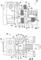
FIG. 1 illustrates a perspective view of an example linear volume shuttle fluid pump according to embodiments of the present disclosure; -
FIG. 2 illustrates a top view of the linear volume shuttle fluid pump depicted inFIG. 1 according to embodiments of the present disclosure; -
FIG. 3 illustrates a perspective view of an example linear volume shuttle fluid pump according to embodiments of the present disclosure; -
FIG. 4 illustrates another view of the linear volume shuttle fluid pump depicted inFIG. 3 according to embodiments of the present disclosure; -
FIG. 5 illustrates a top view of an example linear volume shuttle fluid pump according to embodiments of the present disclosure; -
FIG. 6 illustrates a perspective view of the linear volume shuttle fluid pump depicted inFIG. 5 according to embodiments of the present disclosure; -
FIG. 7 illustrates a perspective view of an example linear volume shuttle fluid pump according to embodiments of the present disclosure; -
FIG. 8 illustrates a top view of the linear volume shuttle fluid pump depicted inFIG. 7 according to embodiments of the present disclosure; -
FIG. 9 illustrates a perspective view of an example pump housing according to embodiments of the present disclosure; -
FIG. 10 illustrates a top view of an example linear volume shuttle fluid pump according to embodiments of the present disclosure; -
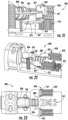
FIGs. 11-12 illustrate close-up views of a detent apparatus of the linear volume shuttle fluid pump depicted inFIG. 10 according to embodiments of the present disclosure; -
FIGs. 13-14 illustrate top views of an example linear volume shuttle fluid pump according to embodiments of the present disclosure; -
FIGs. 15-16 illustrate perspective views of an example linear volume shuttle fluid pump according to embodiments of the present disclosure; -
FIGs. 17-18 illustrate perspective views of an example linear volume shuttle fluid pump according to embodiments of the present disclosure; -
FIGs. 19-20 illustrate perspective views of a contact of the linear volume shuttle fluid pump depicted inFIGs. 17-18 according to embodiments of the present disclosure; -
FIGs. 21-22 illustrate perspective views of an example linear volume shuttle fluid pump according to embodiments of the present disclosure; -
FIG. 23 illustrates a top view of the linear volume shuttle fluid pump depicted inFIGs. 21-22 according to embodiments of the present disclosure; -
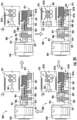
FIG. 24 illustrates a sequence for operating an example linear volume shuttle fluid pump according to embodiments of the present disclosure; -
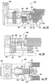
FIGs. 25-26 illustrate perspective views of an example linear volume shuttle fluid pump according to embodiments of the present disclosure; -
FIG. 27 illustrates a top view of the linear volume shuttle fluid pump depicted inFIGs. 25-26 according to embodiments of the present disclosure; -
FIG. 28 illustrates a sequence for operating an example linear volume shuttle fluid pump according to embodiments of the present disclosure; -
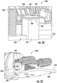
FIGs. 29-30 illustrate perspective views of an example linear volume shuttle fluid pump including an optical sensor according to embodiments of the present disclosure; -
FIG. 31 illustrates a perspective view of an example linear volume shuttle fluid pump including an optical sensor according to embodiments of the present disclosure; -
FIG. 32 illustrates a cross-sectional view of the linear volume shuttle fluid pump depicted inFIG. 31 according to embodiments of the present disclosure; -
FIG. 33 illustrates a perspective view of the linear volume shuttle fluid pump depicted inFIG. 31 according to embodiments of the present disclosure; and -
FIGs. 34-35 illustrate perspective views of an example linear volume shuttle fluid pump including a capacitive sensor according to embodiments of the present disclosure. - The drawings are not necessarily to scale. The drawings are merely representations, not intended to portray specific parameters of the disclosure. The drawings are intended to depict example embodiments of the disclosure, and therefore are not be considered as limiting in scope. In the drawings, like numbering represents like elements.
- Furthermore, certain elements in some of the figures may be omitted, or illustrated not-to-scale, for illustrative clarity. The cross-sectional views may be in the form of "slices", or "nearsighted" cross-sectional views, omitting certain background lines otherwise visible in a "true" cross-sectional view, for illustrative clarity. Furthermore, some reference numbers may be omitted in certain drawings.
- Various approaches in accordance with the present disclosure will now be described more fully hereinafter with reference to the accompanying drawings, where embodiments of the methods are shown. The approaches may be embodied in many different forms and are not to be construed as being limited to the embodiments set forth herein. Instead, these embodiments are provided so this disclosure will be thorough and complete, and will fully convey the scope of the approaches to those skilled in the art.
- Various examples disclosed herein provide a drive mechanism and/or pump system with the ability to control and verify pump sequencing. As a result, a drug delivery device that contains a reservoir and a pump may be made more reliable and thus safer for users.
- Various examples described herein enable a pump, such as a linear volume shuttle pump (LVSP), to execute a pumping cycle in a proper sequence. At any given time during pump actuation, it is beneficial to know the location of different pump components, namely a pump chamber and a piston, as the pump chamber and the piston are responsible for drawing in and expelling fluid. Knowing the location of both the pump chamber and the piston also indicates whether the pump operates in a designed sequence. In some examples of the present disclosure, one or more mechanical detents and sensing/sequencing mechanisms may be implemented with the pump to both control the position of the pump chamber and the piston, thus maintaining the pump cycling in the proper sequence, and to provide feedback as to the position of the pump chamber and/or the piston. As will be described in greater detail herein, multiple methods and devices may be implemented for tracking the location of the chamber and the piston, such as electromechanical contacts, optical sensing, and/or capacitance sensing.
-
FIGs. 1-2 illustrate a linear volume shuttle fluid pump 100 (hereinafter "pump") according to embodiments of the present disclosure. As shown, thepump 100 may include apump housing 102 coupling together afluid reservoir 104, apump chamber 106, and apiston 108. In some embodiments, thefluid reservoir 104 may contain a fluid or liquid drug. Thepump housing 102 may include abase 110, achassis 111 extending from thebase 110 for retaining thepump chamber 106, and areservoir wall 112 operable to interface with thepump chamber 106, as will be described in greater detail herein. Although non-limiting, thepump housing 102 may be formed from an injection molded plastic or other similar material. - Although not shown, the
pump chamber 106 may include an inlet pathway or component and an outlet pathway or component. A liquid or fluid can enter thepump chamber 106 through the inlet pathway and can exit thepump chamber 106 through the outlet pathway. One or more plunger components may operate with the inlet and outlet pathways to draw a fluid into thepump chamber 106 and to expel the fluid from thepump chamber 106. In various examples, thepump chamber 106 may be coupled to thefluid reservoir 104 that stores a fluid or liquid drug. For example, the inlet may be coupled to thefluid reservoir 104 and the outlet pathway may be coupled to a fluid path component (not shown) that is coupled to a patient or user that is to receive the liquid drug stored in thefluid reservoir 104. - As further shown, the
pump 100 may include adetent apparatus 115 coupled to thepump chamber 106. In some embodiments, thedetent apparatus 115 may include a detent cap orbody 116, one ormore detent arms 117 extending from thedetent body 116, and one or moredetent engagement members 118. Thedetent body 116 may extend over and/or abut one end of thepump chamber 106. In some embodiments, thedetent body 116 may further abut thepiston 108, wherein an opening (not shown) of thedetent body 116 may allow a rod of thepiston 108 to pass therethrough. - The
detent arms 117 may include afirst arrest location 120 and asecond arrest location 121. As shown, the first andsecond arrest locations more peaks 122. The first andsecond arrest locations detent engagement member 118, which in this case, is a helical spring extending from thebase 110 of thepump housing 102. The first andsecond arrest locations pump chamber 106 and/or thepiston 108 by adding additional frictional forces to restrict movement of thedetent body 116 prior to a desired time. - In the non-limiting embodiment depicted, the
detent engagement member 118 is in contact with thefirst arrest location 120 of thedetent arm 117 when in a first position. In a second position, thedetent engagement member 118 may be in contact with thesecond arrest location 121 of thedetent arm 117. Thedetent engagement member 118 may change between the first position and second position as thepump chamber 106 moves relative to thefluid reservoir 104. - As further shown, the
pump 100 may include apiston grip 125 coupled to thepiston 108. Thepiston grip 125 may include one ormore grip components 126 engaged with an exterior of thepiston 108. During operation, movement of thepiston grip 125 causes thepiston 108 to move axially relative to thepump chamber 106 to control receipt and delivery of a liquid drug within thepump chamber 106. Thepiston grip 125 may be actuated by a variety of mechanisms and/or actuators. In various examples, thepiston grip 125 may be actuated by an actuator capable of producing reciprocating motion, for example, a piezoelectric-based actuator, a solenoid-based actuator, a Nitinol-based actuator, a spring-based actuator, a rotary motor with a gear drain, a direct current (DC) motor, or any combination thereof. As a result, a desired effect of shuttling fluid (e.g., a liquid drug) may be achieved. - In some embodiments, the
piston grip 125 includes agrip body 127 extending on opposite sides of thepiston 108. Thegrip body 127 may be a generally planar component including one ormore spring footers 128 extending therefrom. As shown, eachspring footer 128 may include one ormore tabs 171 to engage and retain therein aside spring 129. In this embodiment, the side springs 129 may be disposed on opposite sides of thepiston 108, parallel to a central axis (not shown) extending through thepiston 108, thepump chamber 106, and thedetent body 116. The side springs 129 may provide a spring force to bias thepiston grip 125, and thus thepiston 108, towards thepump chamber 106. - As shown in
FIGs. 3-4 , in some embodiments, thepump 100 may include adetent cap 130 positioned atop thedetent engagement members 118 to provide support/rigidity thereto, as thedetent engagement members 118 may be prone to unpredictable bistable behavior. In some embodiments, thedetent cap 130 may include anelongate body 131 extending between free ends of each of thedetent engagement members 118. As shown, avertical shaft 132, which may extend from an underside of theelongate body 131, extends into a center cavity defined by the helical structure of each of thedetent engagement members 118. - Turning now to
FIGs. 5-6 , apump 200 according to embodiments of the present disclosure will be described in greater detail. Thepump 200 may be similar in many aspects to thepump 100 described above. As such, only certain aspects of thepump 200 may be described hereinafter for the sake of brevity. In this embodiment, thepump 200 may include adetent apparatus 215 coupled to apiston rod 234 of apiston 208. Thedetent apparatus 215 may include adetent body 216, which may be coupled to or integrally formed with ahousing 202. Thedetent apparatus 215 may further include one ormore detent arms 217 extending from thepiston rod 234, wherein eachdetent arm 217 includes one or moredetent engagement members 218 engaged with thedetent body 216. In some embodiments, thedetent arms 217 may be rigid or semi-rigid elements extending towards areservoir wall 212 of afluid reservoir 204. Each of thedetent arms 217 may be permit a degree of radial flexing relative to apump chamber 206 as thepump chamber 206 moves axially with respect to thefluid reservoir 204. - The
detent body 216 may include afirst arrest location 220 and asecond arrest location 221. As shown, the first andsecond arrest locations peaks 222 along asidewall 233 of thedetent body 216. In some embodiments, the first andsecond arrest locations detent engagement members 218. The first andsecond arrest locations pump chamber 206 and/or thepiston 208 during use. For example, as thepiston 208 moves relative to thefluid reservoir 204, eachdetent engagement member 218 may move from thefirst arrest location 220 to thesecond arrest location 221. - Turning now to
FIGs. 7-8 , apump 300 according to embodiments of the present disclosure will be described in greater detail. Thepump 300 may be similar in many aspects to thepumps pump 300 may be described hereinafter for the sake of brevity. In this embodiment, thepump 300 may include adetent apparatus 315 coupled to apump chamber 306. Thedetent apparatus 315 may include adetent body 316, which may be coupled to or integrally formed with apump housing 302. For example, thedetent body 316 may correspond to anouter surface 337 of achassis 311 extending from abase 310 of thepump housing 302. - The
detent apparatus 315 may further include one ormore detent arms 317 extending from anexterior surface 345 of thepump chamber 306. As shown, thedetent arms 317 may generally extend radially away from thepump chamber 306. Eachdetent arm 317 may include anopening 335 receiving adetent engagement member 318 therein. In this embodiment, thedetent engagement members 318 may be helical springs extending from thebase 310 of thepump housing 302. As shown, thedetent engagement members 318 may be joined together by aconnector 338 to provide rigidity and support thereto. Furthermore, theconnector 338 may provide an electrical connection between each of thedetent engagement members 318. - The
detent body 316 may include afirst arrest location 320 and asecond arrest location 321. As shown, the first andsecond arrest locations peaks 322 along theouter surface 337 of thedetent body 316. In some embodiments, the first andsecond arrest locations detent engagement members 318. The first andsecond arrest locations pump chamber 306 and/or the piston 308 during use. - In this embodiment, the
detent body 316 may include one or more embedded contact signal pins 344 therein. As shown, the contact signal pins 344 may be positioned within thesecond arrest location 321. In other embodiments, the contact signal pins 344 may be positioned within thefirst arrest location 320, or within both the first andsecond arrest locations second arrest locations contact signal pin 344 in each of the first andsecond arrest locations pump chamber 306, and a distinct contact signal pin in corresponding arrest locations on an opposite side of thepump chamber 306. - During use of the
pump 300, the contact signal pins 344 may not be in contact with thedetent engagement members 318 when thepump chamber 306 is in a first position. When thepump chamber 306 moves away from areservoir wall 312 of afluid reservoir 304 and into a second position within thesecond arrest location 321, the contact signal pins 344 come into contact with thedetent engagement members 318. A closed circuit is then formed between the contact signal pins 344 and thedetent engagement members 318, causing a signal to be delivered to a processor or control logic/circuitry (not shown). For example, the signal obtained by actuating the closed-circuit switch may be an indicator of the status or position of thepump chamber 306. The information obtained by the switch about the position of thepump chamber 306 can be used, for example, to ensure that thepump 300 is drawing in or expelling fluid appropriately. - Turning now to
FIG. 9 , thepump housing 302 of thepump 300 according to embodiments of the present disclosure will be described in greater detail. As shown, thepump housing 302 may include thebase 310 and thechassis 311 extending from thebase 310 for retaining the pump chamber 306 (FIGs. 7-8 ). Thepump housing 302 may further include areservoir housing 350 defining or containing thefluid reservoir 304, wherein the fluid reservoir contains a fluid drug therein. Thereservoir wall 312 may extend along an exterior of thereservoir housing 350, thereservoir wall 312 including afluid opening 351 formed therethrough. In some embodiments, a needle (not shown) may extend through thefluid opening 351 to draw the fluid drug into thepump chamber 306. - In other embodiments, a piston rod of the piston 308 may extend into the
fluid opening 351, initially blocking the fluid drug from being released from thefluid reservoir 304. When the piston rod is withdrawn from thereservoir housing 350, e.g., axially away from thereservoir wall 312, the fluid drug may be released from thefluid reservoir 304 and into thepump chamber 306. In some embodiments, movement of the piston rod can create a vacuum within a portion of thepump chamber 306, such as within a fluid line. The vacuum can pull a portion of the fluid drug out of thefluid reservoir 304 and into the created space/volume within thepump chamber 306. - As further shown, the
chassis 311 may include a first (proximal)end 353 and a second (distal)end 354. Atrough 355 may be provided in thechassis 311 to support thepump chamber 306. During use, thepump chamber 306 may slide within thetrough 355, between the first and second ends 353, 354. Thebase 310 of thepump housing 302 may further include one ormore openings 356 for receiving one or more contact members (not shown). - Referring to
FIGs. 10-12 , apump 400 according to embodiments of the present disclosure will be described in greater detail. Thepump 400 may be similar in many aspects to the pumps described above. As such, only certain aspects of thepump 400 may be described hereinafter for the sake of brevity. In this embodiment, thepump 400 may include adetent apparatus 415 coupled to apump chamber 406. In some embodiments, thedetent apparatus 415 may include a detent cap orbody 416, one ormore detent arms 417 extending from thedetent body 416, and one or moredetent engagement members 418. Thedetent body 416 may extend over and/or abut one end of thepump chamber 406. In some embodiments, thedetent body 416 may further abut apiston 408, wherein an opening (not shown) of thedetent body 416 may allow a rod of thepiston 408 to pass therethrough. - The
detent arms 417 may include afirst arrest location 420 and asecond arrest location 421. As shown, the first andsecond arrest locations more peaks 422. The first andsecond arrest locations detent engagement members 418, which in this case, are torsion springs extending from abase 410 of thepump housing 402. More specifically, thedetent engagement members 418 may include acontact section 458 connected to ahelical section 459. In some embodiments, thehelical section 459 may be housed or embedded within a spring housing 460 (FIG. 12 ), which may extend from, or be integrally formed with, thebase 410. The first andsecond arrest locations pump chamber 406 and/or thepiston 408 by adding additional frictional forces to restrict movement of thedetent apparatus 415 prior to a desired time. - In the non-limiting embodiment depicted, the
contact section 458 of thedetent engagement member 418 may be retained in physical and/or electrical contact with thefirst arrest location 420 of thedetent arm 417 when in a first position. In a second position, thecontact section 458 of thedetent engagement member 418 may be retained in physical and/or electrical contact with thesecond arrest location 421 of thedetent arm 417. Thedetent engagement member 418 may change between the first position and second position as thepump chamber 406 moves away from areservoir wall 412. - Referring to
FIGs. 13-14 , apump 500 according to embodiments of the present disclosure will be described in greater detail. Thepump 500 may be similar in many aspects to the pumps described above. As such, only certain aspects of thepump 500 may be described hereinafter for the sake of brevity. In this embodiment, thepump 500 may include adetent apparatus 515 coupled to apump chamber 506. In some embodiments, thedetent apparatus 515 may include a detent cap orbody 516, one ormore detent arms 517 extending from thedetent body 516, and one or moredetent engagement members 518. Thedetent body 516 may extend over and/or abut one end of thepump chamber 506. In some embodiments, thedetent body 516 may further abut apiston 508, wherein an opening (not shown) of thedetent body 516 may allow a rod 534 (FIG. 14 ) of thepiston 508 to pass therethrough. - The
detent arms 517 may include afirst arrest location 520 and asecond arrest location 521. As shown, the first andsecond arrest locations more peaks 522. The first andsecond arrest locations detent engagement member 518, which in this case, may be a helical spring extending from abase 510 of thepump housing 502. The first andsecond arrest locations pump chamber 506 and/or thepiston 508 by adding additional frictional forces to restrict movement of thedetent apparatus 515 prior to a desired time. - In this embodiment, one or more of the
detent engagement members 518 may include aninsulative coating 562 formed thereon. As shown, theinsulative coating 562 may be formed along just a portion of the detent arms such that thefirst arrest location 520 remains uncovered by theinsulative coating 562. During use, as thepump chamber 506 and thedetent apparatus 515 move away from a fluid reservoir 504, thedetent arms 517 are repositioned relative to thedetent engagement members 518 from thefirst arrest location 520 to thesecond arrest location 521, thus terminating electrical contact between thedetent engagement members 518 anddetent arms 517 due to the presence of theinsulative coating 562. In other embodiments, thefirst arrest location 520 may be covered by theinsulative coating 562, while thesecond arrest location 521 is uncovered by theinsulative coating 562. As such, movement from thefirst arrest location 520 to thesecond arrest location 521 by thedetent engagement members 518 may cause a closed circuit to be formed between thedetent engagement members 518 anddetent arms 517. A signal representing the closed/open circuit connection between thedetent engagement members 518 anddetent arms 517 may be used to determine a position of thepump chamber 506 and/or thepiston 508. - Referring to
FIGs. 15-16 , apump 600 according to embodiments of the present disclosure will be described in greater detail. Thepump 600 may be similar in many aspects to the pumps described above. As such, only certain aspects of thepump 600 may be described hereinafter for the sake of brevity. - As shown, the
pump 600 may include one ormore contact members 664, such as helical springs, extending from abase 610 of apump housing 602. The contact member(s) 664 may form a closed circuit when contact is made with aperimeter 665 of adetent body 616 of adetent apparatus 615. For example, when apump chamber 606 is in a first position adjacent areservoir housing 650, as shown inFIG. 15 , an open circuit is present. As thepump chamber 606 and thedetent apparatus 615 are moved towards adistal end 654 of achassis 611, theperimeter 665 of thedetent body 616 makes electrical and mechanical contact with the contact member(s) 664 to form aclosed circuit 670, as shown by a series of connected arrows inFIG. 16 . A signal representing the closed/open circuit connection between thedetent body 616 and the contact member(s) 664 may be used to determine a position of thepump chamber 606 and/or a piston 608. - In
FIGs. 17-20 , apump 700 according to embodiments of the present disclosure will be described in greater detail. Thepump 700 may be similar in many aspects to the pumps described above. As such, only certain aspects of thepump 700 may be described hereinafter for the sake of brevity. - As shown, the
pump 700 may include one ormore contact members 764, such as helical springs, extending from abase 710 of apump housing 702. Thecontact members 764 may form a closed circuit when contact is made with acontact 767 of adetent body 716 of adetent apparatus 715. In this embodiment, thecontact 767 may be an L-shaped contact extending from thedetent body 716. As best demonstrated inFIGs. 19-20 , thecontact 767 may include a set of curledsides 768 operable to electrically and mechanically engage thecontact members 764. For example, thecontact 767 may extend between each of thecontact members 764, deflecting thecontact members 764 outwardly from a central axis (not shown) extending through an opening 769 (FIG. 19 ) of thedetent body 716. It will be appreciated that the specific geometry and configuration of thecontact 767 are non-limiting. - During use, when a pump chamber 706 is in a first position adjacent a
reservoir housing 750, as shown inFIG. 17 , an open circuit exists. As the pump chamber 706 and thedetent apparatus 715 move towards adistal end 754 of achassis 711, thecontact 767 makes electrical and mechanical contact with thecontact members 764 to form aclosed circuit 770, as shown by a series of connected arrows inFIG. 18 . A signal representing the closed/open circuit connection between thecontact 767 and thecontact members 764 may be used to determine a position of the pump chamber 706 and/or a piston 708. - Referring to
FIGs. 21-23 , apump 800 according to embodiments of the present disclosure will be described in greater detail. Thepump 800 may be similar in many aspects to the pumps described above. As such, only certain aspects of thepump 800 may be described hereinafter for the sake of brevity. In this embodiment, thepump 800 may include apiston grip 825 coupled to apiston 808. Thepiston grip 825 may include one ormore grip components 826 engaged with an exterior of thepiston 808. During operation, movement of thepiston grip 825 causes thepiston 808 to move axially relative to apump chamber 806 to control receipt and delivery of a liquid drug within thepump chamber 806. - In some embodiments, the
piston grip 825 includes agrip body 827 extending on opposite sides of thepiston 808. Thegrip body 827 may include one ormore spring footers 828 extending therefrom. As shown, eachspring footer 828 may include one ormore tabs 871 to engage and retain therein aside spring 830. In this embodiment, the side springs 830 may be disposed on opposite sides of thepiston 808, parallel to a central axis (not shown) extending through thepiston 808, thepump chamber 806, and adetent body 816. The side springs 830 provide a spring force to bias thepiston grip 825, and thus thepiston 808, towards thepump chamber 806. - In this embodiment, the
piston grip 825 may further include acontact 867 coupled thereto. Although non-limiting, thecontact 867 may be an insulated dowel pin disposed along an underside of thegrip body 827. For example, thecontact 867 may be an electrically conductive cylinder generally extending parallel to the central axis. In some embodiments, thecontact 867 may include afirst end 872 retained within aclamp 873 of thepiston grip 825, and a second,free end 874 opposite thefirst end 872. Thefree end 874 is operable to engage one or more pistonposition contact members 875, as will be described below. - Turning now to
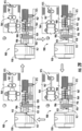
FIG. 24 , operation of thepump 800 according to embodiments of the present disclosure will be described in greater detail. As shown, for each state of thepump 800, both a side view of thepump 800 and a close-up, top view of thecontact 867 and the pistonposition contact members 875 are depicted. In an initial stage (1), thepump chamber 806 may be directly adjacent and/or in abutment with areservoir wall 812 of areservoir housing 850. Additionally, anengagement member 818 may be retained in direct physical contact with afirst arrest location 820 of adetent arm 817 when thepump chamber 806 is in the initial stage (1). As shown, no contact is made, for example, between thedetent body 816 and thecontact members 864, or between thecontact 867 and the pistonposition contact members 875. - Next, at a second stage (2), the
piston 808 may move axially away from thepump chamber 806 to draw a liquid drug into thepump chamber 806. More specifically, apiston rod 834 of thepiston 808 may be withdrawn axially through thepump chamber 806 to release a fluid drug from thereservoir housing 850. As shown, thepiston grip 825 and thecontact 867 may also move axially away from thepump chamber 806, causing thecontact 867 to engage afirst pair 875A of the pistonposition contact members 875. A signal may be delivered from the pistonposition contact members 875 to indicate a position of thecontact 867 and thus thepiston 808. An open circuit between thedetent body 816 and thecontact members 864 may provide an indication of a position of thepump chamber 806. - Next, at a third stage (3), the
pump chamber 806 and thepiston 808 may move axially away from thereservoir housing 850 to bring a needle (not shown) of thepump chamber 806 into a fluid output position. As shown, thepiston grip 825 and thecontact 867 may engage thefirst pair 875A and asecond pair 875B of the pistonposition contact members 875. A signal may be delivered from the pistonposition contact members 875 to indicate a position of thecontact 867 and thus thepiston 808. Furthermore, a closed circuit between thedetent body 816 and thecontact members 864 may also provide an indication of a position of thepump chamber 806. As shown, thedetent engagement member 818 may be retained in direct physical contact with asecond arrest location 821 of thedetent arm 817. - Next, at a fourth stage (4), the
piston 808 may move axially towards thepump chamber 806 to expel the fluid drug from thepump chamber 806. As shown, thepiston grip 825 and thecontact 867 may engage only thefirst pair 875A of the pistonposition contact members 875. A signal may be delivered from the pistonposition contact members 875 to indicate a position of thecontact 867 and thus thepiston 808. Furthermore, the closed circuit between thedetent body 816 and thecontact members 864 may also provide an indication of a position of thepump chamber 806. As shown, thedetent engagement member 818 may remain in direct physical contact with asecond arrest location 821 of thedetent arm 817 at the fourth stage. - Referring now to
FIGs. 25-27 , apump 900 according to embodiments of the present disclosure will be described in greater detail. Thepump 900 may be similar in many aspects to the pumps described above. As such, only certain aspects of thepump 900 may be described hereinafter for the sake of brevity. In this embodiment, thepump 900 may include apiston grip 925 coupled to apiston 908. Thepiston grip 925 may include one ormore grip components 926 engaged with an exterior of thepiston 908. During operation, movement of thepiston grip 925 causes thepiston 908 to move axially relative to thepump chamber 906 and to areservoir housing 950 containing a fluid drug. - In some embodiments, the
piston grip 925 includes agrip body 927 extending on opposite sides of thepiston 908, and acontact 967 coupled thereto. Although non-limiting, thecontact 967 may be a dowel pin disposed along an underside of thegrip body 927. For example, thecontact 967 may be an electrically conductive cylinder generally extending parallel to the central axis. Thecontact 967 may include afirst end 972proximate contact members 964 and asecond end 974 proximate one or more pistonposition contact members 975. As shown, thecontact 967 may be joined to thegrip body 927 by one ormore clamps 973. - Turning now to
FIG. 28 , operation of thepump 900 according to embodiments of the present disclosure will be described in greater detail. As shown, for each state of thepump 900, both a side view of thepump 900 and a close-up, top view of thecontact 967, thecontact members 964, and the pistonposition contact members 975 are depicted. In an initial stage (1), thepump chamber 906 may be directly adjacent and/or in abutment with areservoir wall 912 of areservoir housing 950. Additionally, anengagement member 918 may be retained in direct physical contact with afirst arrest location 920 of adetent arm 917 when thepump chamber 906 is in the initial stage (1). As shown, thecontact 967 may be in direct physical and electrical contact with thecontact members 964, but not the pistonposition contact members 975. - Next, at a second stage (2), the
piston 908 may move axially away from thepump chamber 906 to draw a liquid drug into thepump chamber 906. More specifically, apiston rod 934 of thepiston 908 may be withdrawn axially through thepump chamber 906 to release a fluid drug from thereservoir housing 950. As shown, thepiston grip 925 and thecontact 967 may also move axially away from thepump chamber 906, causing thecontact 967 to engage the pistonposition contact members 975. A signal may be delivered from the pistonposition contact members 975 and thecontact members 964 to indicate a position of thecontact 967 and thus thepiston 908. - Next, at a third stage (3), the
pump chamber 906 and thepiston 908 may move axially away from thereservoir housing 950 to bring a needle (not shown) of thepump chamber 906 into a fluid output position. As shown, thepiston grip 925 and thecontact 967 may continue to move axially away from thereservoir housing 950, causing thefirst end 972 of thecontact 967 to break contact with thecontact members 964. One or more signals may be delivered from the pistonposition contact members 975 and thecontact members 964 to indicate a position of thecontact 967 and thus thepiston 908. In some embodiments, a closed circuit between thedetent body 916 and thecontact members 964 may also provide an indication of a position of thepump chamber 906. As shown, thedetent engagement member 918 may be retained in direct physical contact with asecond arrest location 921 of thedetent arm 917. - Next, at a fourth stage (4), the
piston 908 may move axially towards thepump chamber 906 to expel the fluid drug from thepump chamber 906. As shown, thecontact 967 may again engage both the pistonposition contact members 975 and thecontact members 964. A signal may be delivered from the pistonposition contact members 975 and thecontact members 964 to indicate a position of thecontact 967 and thus thepiston 908. Furthermore, the closed circuit between thedetent body 916 and thecontact members 964 may also provide an indication of a position of thepump chamber 906. As shown, thedetent engagement member 918 may remain in direct physical contact with asecond arrest location 921 of thedetent arm 917 at the fourth stage. - Turning now to
FIGs. 29-30 , apump 1000 according to embodiments of the present disclosure will be described in greater detail. Thepump 1000 may be similar in many aspects to the pumps described above. As such, only certain aspects of thepump 1000 may be described hereinafter for the sake of brevity. In this embodiment, thepump 1000 may include apiston grip 1025 coupled to apiston 1008. Thepiston grip 1025 may include one ormore grip components 1026 engaged with an exterior of thepiston 1008. During operation, thepiston grip 1025 and thepiston 1008 may move together, axially relative to apump chamber 1006. - In some embodiments, the
piston grip 1025 includes agrip body 1027 extending on opposite sides of thepiston 1008. Thegrip body 1027 may further include asensor plate 1080 extending between a pair of side springs 1030. Asensor arm 1082 may extend perpendicularly from thesensor plate 1080, wherein thesensor arm 1082 operates with an optical sensor 1085 to detect a position of thepiston grip 1025 and thus thepiston 1008. More specifically, as better shown inFIG. 30 , thesensor arm 1082 may travel between a light source 1083 (e.g., LED) and aphotodiode 1084. Thelight source 1083 and thephotodiode 1084 may extend from abase 1010 of ahousing 1002. - The
photodiode 1084 is operable to detect light from thelight source 1083. When thesensor arm 1082 is positioned between thelight source 1083 and thephotodiode 1084, the photodiode will not detect any light. When thesensor arm 1082 is not positioned between thelight source 1083 and thephotodiode 1084, the photodiode will detect the light output from thelight source 1083. Based on the detection or non-detection of light, the position of thepiston grip 1025 and thus thepiston 1008 can be determined. - Turning now to
FIGs. 31-33 , apump 1100 according to embodiments of the present disclosure will be described in greater detail. Thepump 1100 may be similar in many aspects to the pumps described above. As such, only certain aspects of thepump 1100 may be described hereinafter for the sake of brevity. In this embodiment, thepump 1100 may include apiston grip 1125 coupled to apiston 1108. During operation, movement of thepiston grip 1125 causes thepiston 1108 to move axially relative to apump chamber 1106 and/or apiston rod 1134. - In some embodiments, the
piston grip 1125 includes agrip body 1127 extending on opposite sides of thepiston 1108. Thegrip body 1127 may further include asensor plate 1180 extending between a pair of side springs 1130. As further shown, thesensor plate 1180 may positioned distal of thepiston 1108. In this embodiment, thesensor plate 1180 may include anoptical opening 1186 positioned above anoptical sensor 1185. Light from a light source (not shown), may reach aphotodiode 1184 of theoptical sensor 1185 depending on a position of thesensor plate 1180. For example, when a solid portion 1187 of the sensor arm 1182 is positioned between the light source and thephotodiode 1184, the photodiode will not detect any light. However, when theoptical opening 1186 is positioned over thephotodiode 1184, light from the light source is permitted to reach thephotodiode 1184. Based on the detection or non-detection of light by thephotodiode 1184, the position of thepiston grip 1125 and thus thepiston 1108 can be determined. In some embodiments, theoptical sensor 1185 can be elevated to a position proximate thegrip body 1127 by asensor block 1190 extending from abase 1110 of ahousing 1102 of thepump 1100. Embodiments herein are not limited in this context, however. - Turning now to
FIGs. 34-35 , apump 1200 according to embodiments of the present disclosure will be described in greater detail. Thepump 1200 may be similar in many aspects to the pumps described above. As such, only certain aspects of thepump 1200 may be described hereinafter for the sake of brevity. In this embodiment, thepump 1200 may include apiston grip 1225 coupled to apiston 1208. During operation, movement of thepiston grip 1225 causes thepiston 1208 to move axially relative to apump chamber 1206. - In some embodiments, the
piston grip 1225 includes agrip body 1227 extending on opposite sides of thepiston 1208. Thegrip body 1227 may operate with acapacitive sensor 1285. For example, thecapacitive sensor 1285 may include acapacitive plate 1294 mounted atop acapacitor block 1295 extending from abase 1210 of ahousing 1202. During use, a temporary capacitor may be formed whengrip body 1227, which is grounded, moves above thecapacitive plate 1294. The capacitance can be measured, for example, by a component on a logic board (not shown) and can directly indicate the location of the piston grip 1215 and thus thepiston 1208. This approach can offer multiple degrees of resolution between pump states since the capacitance measured by thecapacitive sensor 1285 increases and decreases linearly with the motion of thegrip body 1227 of thecapacitive plate 1294. - In sum, the systems, apparatuses, and methods disclosed herein may be used to extract a portion of a liquid drug or other fluid from a reservoir. The pumps disclosed herein may be the linear shuttle pumps and/or and linear volume shuttle fluid pumps for providing a stored liquid drug to a user by, for example, extracting a liquid drug from a reservoir, temporarily storing the extracted liquid drug within the pump, and then expelling the liquid drug from the pump for delivery to the patient. Each of the disclosed pumps may be part of a wearable medical device such as, for example, a wearable insulin delivery device.
- The foregoing discussion has been presented for purposes of illustration and description and is not intended to limit the disclosure to the form or forms disclosed herein. For example, various features of the disclosure may be grouped together in one or more aspects, embodiments, or configurations for the purpose of streamlining the disclosure. However, it should be understood that various features of the certain aspects, embodiments, or configurations of the disclosure may be combined in alternate aspects, embodiments, or configurations.
- As used herein, an element or step recited in the singular and proceeded with the word "a" or "an" should be understood as not excluding plural elements or steps, unless such exclusion is explicitly recited. Furthermore, references to "one embodiment" of the present disclosure are not intended to be interpreted as excluding the existence of additional embodiments that also incorporate the recited features.
- The use of "including," "comprising," or "having" and variations thereof herein is meant to encompass the items listed thereafter and equivalents thereof as well as additional items. Accordingly, the terms "including," "comprising," or "having" and variations thereof are open-ended expressions and can be used interchangeably herein.
- The phrases "at least one", "one or more", and "and/or", as used herein, are open-ended expressions that are both conjunctive and disjunctive in operation. For example, each of the expressions "at least one of A, B and C", "at least one of A, B, or C", "one or more of A, B, and C", "one or more of A, B, or C" and "A, B, and/or C" means A alone, B alone, C alone, A and B together, A and C together, B and C together, or A, B and C together.
- All directional references (e.g., proximal, distal, upper, lower, upward, downward, left, right, lateral, longitudinal, front, back, top, bottom, above, below, vertical, horizontal, radial, axial, clockwise, and counterclockwise) are only used for identification purposes to aid the reader's understanding of the present disclosure, and do not create limitations, particularly as to the position, orientation, or use of this disclosure. Connection references (e.g., attached, coupled, connected, and joined) are to be construed broadly and may include intermediate members between a collection of elements and relative movement between elements unless otherwise indicated. As such, connection references do not necessarily infer that two elements are directly connected and in fixed relation to each other.
- Furthermore, identification references (e.g., primary, secondary, first, second, third, fourth, etc.) are not intended to connote importance or priority but are used to distinguish one feature from another. The drawings are for purposes of illustration only and the dimensions, positions, order and relative sizes reflected in the drawings attached hereto may vary.
- Furthermore, the terms "substantial" or "substantially," as well as the terms "approximate" or "approximately," can be used interchangeably in some embodiments, and can be described using any relative measures acceptable by one of ordinary skill in the art. For example, these terms can serve as a comparison to a reference parameter, to indicate a deviation capable of providing the intended function. Although non-limiting, the deviation from the reference parameter can be, for example, in an amount of less than 1%, less than 3%, less than 5%, less than 10%, less than 15%, less than 20%, and so on.
- Still furthermore, although the various methods disclosed herein are described as a series of acts or events, the present disclosure is not limited by the illustrated ordering of such acts or events unless specifically stated. For example, some acts may occur in different orders and/or concurrently with other acts or events apart from those illustrated and/or described herein, in accordance with the disclosure. In addition, not all illustrated acts or events may be required to implement a methodology in accordance with the present disclosure. Furthermore, the methods may be implemented in association with the formation and/or processing of structures illustrated and described herein as well as in association with other structures not illustrated.
- The present disclosure is not to be limited in scope by the specific embodiments described herein. Indeed, other various embodiments of and modifications to the present disclosure, in addition to those described herein, will be apparent to those of ordinary skill in the art from the foregoing description and accompanying drawings. Thus, such other embodiments and modifications are intended to fall within the scope of the present disclosure. Furthermore, the present disclosure has been described herein in the context of a particular implementation in a particular environment for a particular purpose. Those of ordinary skill in the art will recognize the usefulness is not limited thereto and the present disclosure may be beneficially implemented in any number of environments for any number of purposes. Thus, the claims set forth below are to be construed in view of the full breadth and spirit of the present disclosure as described herein.
- Although the present invention is defined in the attached claims, it should be understood that the present invention can also (alternatively) be defined in accordance with the following embodiments:
- 1. A pump, comprising:
- a pump chamber operably coupled with a piston;
- a detent apparatus coupled to the pump chamber or the piston, wherein the detent apparatus comprises a detent body, a detent arm, and a detent engagement member, wherein in a first position the detent engagement member is retained in contact with a first arrest location of either the detent body or the detent arm, and wherein in a second position the detent engagement member is retained in contact with a second arrest location of either the detent body or the detent arm; and
- a piston grip coupled to the piston, the piston grip including a grip component engaged with an exterior of the piston, wherein movement of the piston grip causes the piston to move axially relative to the pump chamber to control receipt and delivery of a liquid drug.
- 2. The pump of
embodiment 1, further comprising a set of side springs coupled to the piston grip, wherein the set of side springs provide a spring force to bias the piston grip towards the pump chamber. - 3. The pump of
embodiment 1, further comprising a second detent engagement member, wherein a detent cap is positioned atop the detent engagement member and the second detent engagement member. - 4. The pump of
embodiment 1, wherein the detent engagement member is a spring. - 5. The pump of
embodiment 1, wherein the detent body extends from a pump housing, wherein the detent arm is directly coupled to an exterior surface of the pump chamber, and wherein the detent engagement member extends through an opening of the detent arm. - 6. The pump of embodiment 5, further comprising a contact signal pin embedded within the detent body, wherein in the first position the detent engagement member is in contact with the contact signal pin, and wherein in the second position the detent engagement member is not in contact with the contact signal pin.
- 7. The pump of
embodiment 1, further comprising an insulative coating extending along a portion of the detent arm, wherein in the second position the detent engagement member is in direct physical contact with the insulative coating. - 8. The pump of
embodiment 1, further comprising a contact extending from the detent body or the piston grip, wherein the contact is operable to make or break contact with one or more contact members. - 9. The pump of
embodiment 1, further comprising an optical sensor or a capacitive sensor positioned adjacent the piston grip to indicate a position of the piston grip. - 10. A linear volume shuttle pump, comprising:
- a pump chamber operably coupled with a piston;
- a detent apparatus coupled to the pump chamber or the piston, wherein the detent apparatus comprises a detent body, a detent arm, and a detent engagement member, wherein the detent engagement member is operable to move between first and second arrest locations disposed along the detent body or the detent arm; and
- a piston grip coupled to the piston, the piston grip including a grip component engaged with an exterior of the piston, wherein movement of the piston grip causes the piston to move axially relative to the pump chamber to control receipt of a liquid drug from a reservoir and delivery of the liquid drug from the pump chamber.
- 11. The linear volume shuttle pump of
embodiment 10, further comprising a set of side springs coupled to the piston grip, wherein the set of side springs provide a spring force to bias the piston grip towards the pump chamber. - 12. The linear volume shuttle pump of
embodiment 10, wherein the detent engagement member is a spring. - 13. The linear volume shuttle pump of
embodiment 10, wherein the detent body extends from a pump housing, wherein the detent arm is directly coupled to an exterior surface of the pump chamber, and wherein the detent engagement member extends through an opening of the detent arm. - 14. The linear volume shuttle pump of
embodiment 10, further comprising a contact signal pin embedded within the detent body, wherein in the first position the detent engagement member is in direct physical contact with the contact signal pin, and wherein in the second position the detent engagement member is not in direct physical contact with the contact signal pin. - 15. The linear volume shuttle pump of
embodiment 10, further comprising an insulative coating extending along a portion of the detent arm, wherein in a first position the detent engagement member is not in direct physical contact with the insulative coating, and wherein in a second position the detent engagement member is in direct physical contact with the insulative coating. - 16. The linear volume shuttle pump of
embodiment 10, further comprising a contact extending from the detent body or the piston grip, wherein the contact is operable to make or break contact with one or more contact members. - 17. A linear volume shuttle pump, comprising:
- a pump chamber operably coupled with a piston;
- a detent apparatus coupled to the pump chamber or the piston, wherein the detent apparatus comprises a detent body, a detent arm, and a detent engagement member, wherein the detent engagement member is operable to move between first and second arrest locations disposed along the detent body or the detent arm;
- a piston grip coupled to the piston, the piston grip including a grip component engaged with an exterior of the piston, wherein movement of the piston grip causes the piston to move axially relative to the pump chamber to control receipt of a liquid drug from a reservoir and delivery of the liquid drug from the pump chamber; and
- a contact extending from the detent apparatus or the piston grip, the contact operable to make or break contact with one or more contact members coupled to a pump housing.
- 18. The linear volume shuttle pump of embodiment 17, wherein the detent body extends from a pump housing, wherein the detent arm is directly coupled to an exterior surface of the pump chamber, and wherein the detent engagement member extends through an opening of the detent arm.
- 19. The linear volume shuttle pump of embodiment 18, further comprising a contact signal pin embedded within the detent body, wherein in a first position the detent engagement member is in contact with the contact signal pin, and wherein in a second position the detent engagement member is not in contact with the contact signal pin.
- 20. The linear volume shuttle pump of embodiment 17, wherein the contact includes a perimeter of the detent body, the detent engagement member, or an L-shaped contact component extending from the perimeter of the detent body, and wherein the one or more contact members includes a spring extending from the pump housing, an embedded contact signal pin, or a pin coupled to the piston grip.
Claims (14)
- A pump (1200), comprising:a pump chamber (1206) operably coupled with a piston (1208);a detent apparatus (115; 215; 315; 415; 515; 615; 715) coupled to the pump chamber (1206) or the piston (1208), wherein the detent apparatus comprises a detent body (116; 216; 316; 416; 516; 616; 716; 816; 916), a detent arm (117; 217; 317; 417; 517; 617; 717; 817; 917), and a detent engagement member (118; 218; 318; 418; 518; 818; 918), wherein in a first position the detent engagement member is retained in contact with a first arrest location (120; 220; 320; 420; 520; 820; 920) of either the detent body or the detent arm, and wherein in a second position (121; 221; 321; 421; 521; 821; 921) the detent engagement member is retained in contact with a second arrest location of either the detent body or the detent arm;a piston grip (1225) coupled to the piston (1208), the piston grip including a grip component engaged with an exterior of the piston (1208), wherein movement of the piston grip causes the piston (1208) to move axially relative to the pump chamber (1206) to control receipt and delivery of a liquid drug; anda capacitive sensor (1285) positioned adjacent the piston grip (1225) to indicate a position of the piston grip (1225).
- The pump of claim 1, wherein the piston grip (1225) includes a grip body (1227) extending on opposite sides of the piston (1208) which is designed to operate with the capacitive sensor (1285).
- The pump of claim 1 or 2, wherein the capacitive sensor (1285) includes a capacitive plate (1294) mounted atop a capacitor block (1295) extending from a base (1210) of a housing (1202).
- The pump of claim 3, wherein a temporary capacitor is formed when grip body (1227), which is grounded, moves above the capacitive plate (1294).
- The pump of one of claims 1 to 4, wherein the capacitance is measured by a component on a logic board for directly indicating the location of the piston grip (1215) and thus the piston (1208).
- The pump of one of claims 3 to 5, wherein the capacitance measured by the capacitive sensor (1285) increases and decreases linearly with the motion of the grip body (1227) of the capacitive plate (1294).
- The pump of one of claims 1 to 6, further comprising a set of side springs coupled to the piston grip, wherein the set of side springs provide a spring force to bias the piston grip towards the pump chamber.
- The pump of one of claims 1 to 7, further comprising a second detent engagement member, wherein a detent cap is positioned atop the detent engagement member and the second detent engagement member.
- The pump of one of claims 1 to 8, wherein the detent engagement member is a spring.
- The pump of one of claims 1 to 9, wherein the detent body extends from a pump housing, wherein the detent arm is directly coupled to an exterior surface of the pump chamber, and wherein the detent engagement member extends through an opening of the detent arm.
- The pump of one of claims 1 to 10, further comprising a contact signal pin embedded within the detent body, wherein in the first position the detent engagement member is in contact with the contact signal pin, and wherein in the second position the detent engagement member is not in contact with the contact signal pin.
- The pump of one of claims 1 to 11, further comprising an insulative coating extending along a portion of the detent arm, wherein in the second position the detent engagement member is in direct physical contact with the insulative coating.
- The pump of one of claims 1 to 12, further comprising a contact extending from the detent body or the piston grip, wherein the contact is operable to make or break contact with one or more contact members.
- Wearable medical device comprising a pump according to one of the preceding claims.
Priority Applications (1)
| Application Number | Priority Date | Filing Date | Title |
|---|---|---|---|
| EP24205751.1A EP4467174A3 (en) | 2019-11-05 | 2019-11-05 | Component positioning of a linear shuttle pump |
Applications Claiming Priority (3)
| Application Number | Priority Date | Filing Date | Title |
|---|---|---|---|
| EP24205751.1A EP4467174A3 (en) | 2019-11-05 | 2019-11-05 | Component positioning of a linear shuttle pump |
| EP19809352.8A EP4054677A1 (en) | 2019-11-05 | 2019-11-05 | Component positioning of a linear shuttle pump |
| PCT/US2019/059854 WO2021091537A1 (en) | 2019-11-05 | 2019-11-05 | Component positioning of a linear shuttle pump |
Related Parent Applications (1)
| Application Number | Title | Priority Date | Filing Date |
|---|---|---|---|
| EP19809352.8A Division EP4054677A1 (en) | 2019-11-05 | 2019-11-05 | Component positioning of a linear shuttle pump |
Publications (2)
| Publication Number | Publication Date |
|---|---|
| EP4467174A2 true EP4467174A2 (en) | 2024-11-27 |
| EP4467174A3 EP4467174A3 (en) | 2025-02-26 |
Family
ID=68655765
Family Applications (3)
| Application Number | Title | Priority Date | Filing Date |
|---|---|---|---|
| EP24205751.1A Pending EP4467174A3 (en) | 2019-11-05 | 2019-11-05 | Component positioning of a linear shuttle pump |
| EP24205753.7A Pending EP4467175A3 (en) | 2019-11-05 | 2019-11-05 | Component positioning of a linear shuttle pump |
| EP19809352.8A Pending EP4054677A1 (en) | 2019-11-05 | 2019-11-05 | Component positioning of a linear shuttle pump |
Family Applications After (2)
| Application Number | Title | Priority Date | Filing Date |
|---|---|---|---|
| EP24205753.7A Pending EP4467175A3 (en) | 2019-11-05 | 2019-11-05 | Component positioning of a linear shuttle pump |
| EP19809352.8A Pending EP4054677A1 (en) | 2019-11-05 | 2019-11-05 | Component positioning of a linear shuttle pump |
Country Status (4)
| Country | Link |
|---|---|
| EP (3) | EP4467174A3 (en) |
| CN (2) | CN114828915B (en) |
| AU (1) | AU2019473403B2 (en) |
| WO (1) | WO2021091537A1 (en) |
Family Cites Families (13)
| Publication number | Priority date | Publication date | Assignee | Title |
|---|---|---|---|---|
| JP3381301B2 (en) * | 1993-04-14 | 2003-02-24 | 株式会社ジェイ・エム・エス | Syringe pump |
| EP2275158B1 (en) * | 2001-05-16 | 2013-01-23 | Eli Lilly and Company | Medication injector apparatus |
| KR20050092105A (en) * | 2005-05-19 | 2005-09-20 | 엠프레사 브라질리에라 데 콤프레소레스 에스.아.-엠브라코 | A control system for the movement of a piston |
| WO2009141005A1 (en) * | 2008-05-20 | 2009-11-26 | Tecpharma Licensing Ag | Device for administering an injectable product comprising a residual amount display |
| FR2937723B1 (en) * | 2008-10-27 | 2018-12-07 | Sensile Medical Ag | CARTRIDGE WITH FILLING LEVEL DETECTION |
| US8920376B2 (en) * | 2010-04-20 | 2014-12-30 | Minipumps, Llc | Fill-status sensors for drug pump devices |
| SG10201800584SA (en) * | 2012-12-21 | 2018-03-28 | Deka Products Lp | Syringe pump system |
| AU2015231365B2 (en) * | 2014-03-21 | 2019-12-05 | Osprey Medical, Inc. | Syringe with optical system for monitoring the position of the plunger rod |
| DK3328465T3 (en) * | 2015-07-31 | 2020-06-15 | Sanofi Aventis Deutschland | SENSOR FOR A PHARMACEUTICAL DELIVERY DEVICE |
| WO2017148855A1 (en) * | 2016-03-01 | 2017-09-08 | Novo Nordisk A/S | Switch arrangement for drug delivery device with data capture |
| CN109310828B (en) * | 2016-05-30 | 2022-09-16 | 诺和诺德股份有限公司 | Mounting features for accessory devices |
| KR101860928B1 (en) * | 2016-10-18 | 2018-05-24 | 이오플로우 주식회사 | Medical liquid dispensing device |
| US20200230325A1 (en) * | 2017-09-30 | 2020-07-23 | Novo Nordisk A/S | Cartridge system for a drug delivery device |
-
2019
- 2019-11-05 CN CN201980102808.1A patent/CN114828915B/en active Active
- 2019-11-05 AU AU2019473403A patent/AU2019473403B2/en active Active
- 2019-11-05 WO PCT/US2019/059854 patent/WO2021091537A1/en not_active Ceased
- 2019-11-05 EP EP24205751.1A patent/EP4467174A3/en active Pending
- 2019-11-05 CN CN202510431665.6A patent/CN120114700A/en active Pending
- 2019-11-05 EP EP24205753.7A patent/EP4467175A3/en active Pending
- 2019-11-05 EP EP19809352.8A patent/EP4054677A1/en active Pending
Also Published As
| Publication number | Publication date |
|---|---|
| EP4467175A3 (en) | 2025-02-19 |
| AU2019473403A1 (en) | 2022-06-09 |
| EP4467174A3 (en) | 2025-02-26 |
| WO2021091537A1 (en) | 2021-05-14 |
| CA3156331A1 (en) | 2021-05-14 |
| EP4467175A2 (en) | 2024-11-27 |
| CN114828915A (en) | 2022-07-29 |
| CN120114700A (en) | 2025-06-10 |
| CN114828915B (en) | 2025-04-29 |
| EP4054677A1 (en) | 2022-09-14 |
| AU2019473403B2 (en) | 2023-10-05 |
Similar Documents
| Publication | Publication Date | Title |
|---|---|---|
| CN212347349U (en) | Rotary metering pump | |
| JP6553216B2 (en) | Blockage detection technology for infusion devices with rotary pump mechanism | |
| CN206175149U (en) | Rotary metering pump | |
| US9993594B2 (en) | Occlusion detection techniques for a fluid infusion device having a rotary pump mechanism and rotor position sensors | |
| US11857756B2 (en) | Rotational metering pump for insulin patch | |
| US9879668B2 (en) | Occlusion detection techniques for a fluid infusion device having a rotary pump mechanism and an optical sensor | |
| US9987425B2 (en) | Occlusion detection techniques for a fluid infusion device having a rotary pump mechanism and sensor contact elements | |
| JP2014504186A (en) | Drug delivery device | |
| US20220233764A1 (en) | Component positioning of a linear shuttle pump | |
| ES2846879T3 (en) | Zero position sensing system for medication delivery device | |
| US9878095B2 (en) | Occlusion detection techniques for a fluid infusion device having a rotary pump mechanism and multiple sensor contact elements | |
| US20160367750A1 (en) | Occlusion detection techniques for a fluid infusion device having a rotary pump mechanism and a force sensor | |
| AU2019473403B2 (en) | Component positioning of a linear shuttle pump | |
| CA3156331C (en) | Component positioning of a linear shuttle pump | |
| US11446435B2 (en) | Drug delivery shuttle pump system and valve assembly | |
| KR20240113558A (en) | Capacitance sensing for component positioning detection | |
| KR102909236B1 (en) | apparatus for infusing medical liquid with solenoid motion detection sensor |
Legal Events
| Date | Code | Title | Description |
|---|---|---|---|
| PUAI | Public reference made under article 153(3) epc to a published international application that has entered the european phase |
Free format text: ORIGINAL CODE: 0009012 |
|
| STAA | Information on the status of an ep patent application or granted ep patent |
Free format text: STATUS: REQUEST FOR EXAMINATION WAS MADE |
|
| 17P | Request for examination filed |
Effective date: 20241010 |
|
| AC | Divisional application: reference to earlier application |
Ref document number: 4054677 Country of ref document: EP Kind code of ref document: P |
|
| AK | Designated contracting states |
Kind code of ref document: A2 Designated state(s): AL AT BE BG CH CY CZ DE DK EE ES FI FR GB GR HR HU IE IS IT LI LT LU LV MC MK MT NL NO PL PT RO RS SE SI SK SM TR |
|
| REG | Reference to a national code |
Ref country code: DE Ref legal event code: R079 Free format text: PREVIOUS MAIN CLASS: A61M0005142000 Ipc: A61M0005145000 |
|
| PUAL | Search report despatched |
Free format text: ORIGINAL CODE: 0009013 |
|
| STAA | Information on the status of an ep patent application or granted ep patent |
Free format text: STATUS: EXAMINATION IS IN PROGRESS |
|
| AK | Designated contracting states |
Kind code of ref document: A3 Designated state(s): AL AT BE BG CH CY CZ DE DK EE ES FI FR GB GR HR HU IE IS IT LI LT LU LV MC MK MT NL NO PL PT RO RS SE SI SK SM TR |
|
| RIC1 | Information provided on ipc code assigned before grant |
Ipc: A61M 5/142 20060101ALI20250117BHEP Ipc: A61M 5/315 20060101ALI20250117BHEP Ipc: A61M 5/168 20060101ALI20250117BHEP Ipc: A61M 5/145 20060101AFI20250117BHEP |
|
| 17Q | First examination report despatched |
Effective date: 20250204 |
|
| REG | Reference to a national code |
Ref country code: DE Ref legal event code: R079 Free format text: PREVIOUS MAIN CLASS: A61M0005145000 Ipc: A61M0005142000 |
|
| GRAP | Despatch of communication of intention to grant a patent |
Free format text: ORIGINAL CODE: EPIDOSNIGR1 |
|
| STAA | Information on the status of an ep patent application or granted ep patent |
Free format text: STATUS: GRANT OF PATENT IS INTENDED |