EP4465779A1 - Photovoltaic-inverter heat-dissipation assembly - Google Patents
Photovoltaic-inverter heat-dissipation assembly Download PDFInfo
- Publication number
- EP4465779A1 EP4465779A1 EP23184141.2A EP23184141A EP4465779A1 EP 4465779 A1 EP4465779 A1 EP 4465779A1 EP 23184141 A EP23184141 A EP 23184141A EP 4465779 A1 EP4465779 A1 EP 4465779A1
- Authority
- EP
- European Patent Office
- Prior art keywords
- heat
- air
- inlet
- dissipation
- inverter
- Prior art date
- Legal status (The legal status is an assumption and is not a legal conclusion. Google has not performed a legal analysis and makes no representation as to the accuracy of the status listed.)
- Granted
Links
Images







Classifications
-
- H—ELECTRICITY
- H05—ELECTRIC TECHNIQUES NOT OTHERWISE PROVIDED FOR
- H05K—PRINTED CIRCUITS; CASINGS OR CONSTRUCTIONAL DETAILS OF ELECTRIC APPARATUS; MANUFACTURE OF ASSEMBLAGES OF ELECTRICAL COMPONENTS
- H05K7/00—Constructional details common to different types of electric apparatus
- H05K7/20—Modifications to facilitate cooling, ventilating, or heating
- H05K7/2089—Modifications to facilitate cooling, ventilating, or heating for power electronics, e.g. for inverters for controlling motor
- H05K7/20909—Forced ventilation, e.g. on heat dissipaters coupled to components
- H05K7/20918—Forced ventilation, e.g. on heat dissipaters coupled to components the components being isolated from air flow, e.g. hollow heat sinks, wind tunnels or funnels
-
- H—ELECTRICITY
- H02—GENERATION; CONVERSION OR DISTRIBUTION OF ELECTRIC POWER
- H02S—GENERATION OF ELECTRIC POWER BY CONVERSION OF INFRARED RADIATION, VISIBLE LIGHT OR ULTRAVIOLET LIGHT, e.g. USING PHOTOVOLTAIC [PV] MODULES
- H02S40/00—Components or accessories in combination with PV modules, not provided for in groups H02S10/00 - H02S30/00
- H02S40/30—Electrical components
- H02S40/34—Electrical components comprising specially adapted electrical connection means to be structurally associated with the PV module, e.g. junction boxes
- H02S40/345—Electrical components comprising specially adapted electrical connection means to be structurally associated with the PV module, e.g. junction boxes with cooling means associated with the electrical connection means, e.g. cooling means associated with or applied to the junction box
-
- H—ELECTRICITY
- H05—ELECTRIC TECHNIQUES NOT OTHERWISE PROVIDED FOR
- H05K—PRINTED CIRCUITS; CASINGS OR CONSTRUCTIONAL DETAILS OF ELECTRIC APPARATUS; MANUFACTURE OF ASSEMBLAGES OF ELECTRICAL COMPONENTS
- H05K7/00—Constructional details common to different types of electric apparatus
- H05K7/20—Modifications to facilitate cooling, ventilating, or heating
- H05K7/2089—Modifications to facilitate cooling, ventilating, or heating for power electronics, e.g. for inverters for controlling motor
- H05K7/20909—Forced ventilation, e.g. on heat dissipaters coupled to components
-
- H—ELECTRICITY
- H02—GENERATION; CONVERSION OR DISTRIBUTION OF ELECTRIC POWER
- H02M—APPARATUS FOR CONVERSION BETWEEN AC AND AC, BETWEEN AC AND DC, OR BETWEEN DC AND DC, AND FOR USE WITH MAINS OR SIMILAR POWER SUPPLY SYSTEMS; CONVERSION OF DC OR AC INPUT POWER INTO SURGE OUTPUT POWER; CONTROL OR REGULATION THEREOF
- H02M7/00—Conversion of AC power input into DC power output; Conversion of DC power input into AC power output
- H02M7/003—Constructional details, e.g. physical layout, assembly, wiring or busbar connections
-
- H—ELECTRICITY
- H02—GENERATION; CONVERSION OR DISTRIBUTION OF ELECTRIC POWER
- H02M—APPARATUS FOR CONVERSION BETWEEN AC AND AC, BETWEEN AC AND DC, OR BETWEEN DC AND DC, AND FOR USE WITH MAINS OR SIMILAR POWER SUPPLY SYSTEMS; CONVERSION OF DC OR AC INPUT POWER INTO SURGE OUTPUT POWER; CONTROL OR REGULATION THEREOF
- H02M7/00—Conversion of AC power input into DC power output; Conversion of DC power input into AC power output
- H02M7/42—Conversion of DC power input into AC power output without possibility of reversal
-
- H—ELECTRICITY
- H02—GENERATION; CONVERSION OR DISTRIBUTION OF ELECTRIC POWER
- H02S—GENERATION OF ELECTRIC POWER BY CONVERSION OF INFRARED RADIATION, VISIBLE LIGHT OR ULTRAVIOLET LIGHT, e.g. USING PHOTOVOLTAIC [PV] MODULES
- H02S40/00—Components or accessories in combination with PV modules, not provided for in groups H02S10/00 - H02S30/00
- H02S40/30—Electrical components
- H02S40/32—Electrical components comprising DC/AC inverter means associated with the PV module itself, e.g. AC modules
-
- H—ELECTRICITY
- H05—ELECTRIC TECHNIQUES NOT OTHERWISE PROVIDED FOR
- H05K—PRINTED CIRCUITS; CASINGS OR CONSTRUCTIONAL DETAILS OF ELECTRIC APPARATUS; MANUFACTURE OF ASSEMBLAGES OF ELECTRICAL COMPONENTS
- H05K7/00—Constructional details common to different types of electric apparatus
- H05K7/20—Modifications to facilitate cooling, ventilating, or heating
- H05K7/2089—Modifications to facilitate cooling, ventilating, or heating for power electronics, e.g. for inverters for controlling motor
- H05K7/209—Heat transfer by conduction from internal heat source to heat radiating structure
Definitions
- the present disclosure relates to a heat-dissipation assembly, and more particularly to a photovoltaic-inverter heat-dissipation assembly having the interior of the assembled housing divided into the first heat-dissipation space and the second heat-dissipation space, and capable of dissipating the heat source through the independent airflow, so as to provide the better heat-dissipation performance and avoid the generation of hot air backflow from affecting the overall heat-dissipation performance.
- a photovoltaic inverter (or PV inverter for short) is a type of power inverter which converts the variable direct current (DC) output of a photovoltaic solar panel into a utility frequency alternating current (AC).
- a PV inverter includes a lot of heat-generating devices accommodated in an assembled housing.
- the power devices such as IGBTs, MOSFETs, etc.
- the boost choke, inverter choke, the boost module, other active or passive components for the inverter module are arranged in the rear chamber of the photovoltaic-inverter assembly.
- the conventional photovoltaic-inverter heat-dissipation assembly includes a group of forced air-cooling fans disposed on a single bottom side, so as to dissipate the heat form many components in the rear chamber.
- the airflow formed by the fans disposed on the bottom side of the heat-dissipation assembly flows through the rear chamber from bottom to top, so as to flow through the boost inductor, the inverter inductor and the heat sinks corresponding to the boost module and the inverter module.
- the heat exchange of the airflow with a heat source may increase the temperature of the airflow by 10 degrees, when the airflow flows through the four heat sources sequentially from bottom to top, the heat from the bottom heat source will transfer to the top heat source and the heat-dissipation performance of the heat-dissipation assembly will be deteriorated.
- An object of the present disclosure is to provide a photovoltaic-inverter heat-dissipation assembly.
- the internal space of the rear chamber is divided into at least two heat-dissipation spaces, which are capable of dissipating the heat source through the independent airflow, respectively, so as to provide the better heat-dissipation performance, avoid the generation of hot air backflow from affecting the overall heat-dissipation performance.
- Each of the at least two heat-dissipation space has an independent fan and an independent air-inlet correspondingly disposed therein, so that at least two independent airflows are formed to effectively dissipate at least two heat-generating devices, respectively.
- the airflows for heat-dissipating in the at least two heat-dissipation space do not interfere with each other.
- the at least two independent airflows are discharged through at least one air-outlet on the top side, respectively, so as to exert a good heat-dissipation effect effectively.
- Another object of the present disclosure is to provide a photovoltaic-inverter heat-dissipation assembly.
- the space of the rear chamber is divided into at least two heat-dissipation spaces, which are isolated from each other, and include an independent fan and an independent air-inlet, respectively.
- the openings of the air-inlets of the at least two heat-dissipation spaces face different directions, so that the mutual interference is reduced and the stability of the independent airflow flowing through the corresponding air-inlet is maintained.
- the flow directions of the independent airflows at the air-outlets are also different from the flow directions of the independent airflows at the corresponding air-inlets.
- the retaining wall structure is located between the air-outlet and the air-inlet, and it facilitates to prevent the airflow flowing through the upper air-outlet from flowing back to the lower air-inlet. It allows to arrange the active components such as the boost module, the inverter module, IGBT, MOSFETF semiconductor switching devices or the passive components such as the capacitors, the boost choke, the inverter choke and the resistors of the PV inverter in the at least two heat-dissipation spaces according to the actual heat-dissipation requirements, so as to exert the best heat-dissipation performance.
- the active components such as the boost module, the inverter module, IGBT, MOSFETF semiconductor switching devices or the passive components such as the capacitors, the boost choke, the inverter choke and the resistors of the PV inverter
- the active components or the passive components with the requirements of waterproof and dustproof are accommodated in the front chamber and thermally coupled to the heat sink in the rear chamber, so as to dissipate the heat through the airflow.
- the active components or the passive components without the requirements of waterproof and dustproof are accommodated in the rear chamber to dissipate the heat through the airflow.
- the at least two heat-dissipation spaces divided from the rear chamber are configured to accommodate different sets of heat sinks or chokes, and the independent airflow in each heat-dissipation space is used to dissipate the heat, so that the occurrence of hot air dissipation or hot air backflow is avoided, and the overall efficiency of heat-dissipation effectively is improved effectively.
- a photovoltaic-inverter heat-dissipation assembly includes a front housing-base, a rear cover, a first heat-generating device, a first fan, a second heat-generating device and a second fan.
- the front housing-base includes a rear mounting surface and a partition element, wherein the partition element is disposed on the rear mounting surface.
- the rear cover is combined with the partition element and the rear mounting surface of the front housing-base to form a first heat-dissipation space and a second heat-dissipation space separated from each other, and includes a first air-inlet, a second air-inlet and at least one air-outlet, wherein the first air-inlet and the second air-inlet are in communication with the at least one air-outlet through the first heat-dissipation space and the second heat-dissipation space, respectively.
- the first heat-generating device is disposed on the rear mounting surface and accommodated in the first heat-dissipation space.
- the first fan is disposed adjacent to the first air-inlet, located between the first air-inlet and the first heat-generating device, and configured to generate a first airflow, which enters through the first air-inlet, flows through the first heating-generating device, and flows out through the at least one air-outlet.
- the second heat-generating device is disposed on the rear mounting surface and accommodated in the second heat-dissipation space.
- the second fan is disposed adjacent to the second air-inlet, located between the second air-inlet and the second heat-generating device, and configured to generate a second airflow, which enters through the second air-inlet, flows through the second heat-generating device, and flows out through the at least one air-outlet.
- first and second features are formed in direct contact
- additional features may be formed between the first and second features, such that the first and second features may not be in direct contact
- present disclosure may repeat reference numerals and/or letters in the various examples. This repetition is for the purpose of simplicity and clarity and does not in itself dictate a relationship between the various embodiments and/or configurations discussed.
- spatially relative terms such as “top,” “bottom,” “front,” “rear” and the like, may be used herein for ease of description to describe one element or feature's relationship to another element(s) or feature(s) as illustrated in the figures.
- the spatially relative terms are intended to encompass different orientations of the device in use or operation in addition to the orientation depicted in the figures.
- the apparatus may be otherwise oriented (rotated 90 degrees or at other orientations) and the spatially relative descriptors used herein may likewise be interpreted accordingly.
- the rear cover 20 is combined with the partition element 13 and the rear mounting surface 12 of the front housing-base 10 to form a first heat-dissipation space 31 and a second heat-dissipation space 41 separated from each other.
- the rear cover 20 includes a first air-inlet 311, a second air-inlet 411 and at least one air-outlet.
- the first air-inlet 311 and the second air-inlet 411 are disposed separately from each other.
- the at least one air-outlet includes a first air-outlet 312 and a second air-outlet 412 spatially corresponding to the first heat-dissipation space 31 and the second heat-dissipation space 41, respectively.
- the first air-inlet 311 is in communication with the first air-outlet 312 through the first heat-dissipation space 31, and the second air-inlet 411 is in communication with the second air-outlet 412 through the second heat-dissipation space 41.
- the first heat-generating device 32 is disposed on the rear mounting surface 12 of the front housing-base 10 and accommodated in the first heat-dissipation space 31.
- the first fan 33 is disposed adjacent to the first air-inlet 311, located between the first air-inlet 311 and the first heat-generating device 32, and configured to generate a first airflow F1.
- the first air-inlet 311 is disposed on the backbone 21 of the rear cover 20.
- the second air-inlet 411 is disposed on the bottom plane 23 of the rear cover 20.
- the space of the rear chamber between the front housing-base 10 and the rear cover 20 is further divided according to the design of the partition element 13, and divided into at least two independent spaces, such as the first heat-dissipation space 31 and the second heat-dissipation space 41 which are isolated from each other.
- the first heat-dissipation space 31 has the first fan 33 and the first air-inlet 311 disposed independently thereon, and the second heat-dissipation space 41 has the second fan 43 and the second air-inlet 411 disposed independently thereon.
- the first air-inlet 311 in communication with to the first heat-dissipation space 31 is disposed on the backbone 21.
- the first air-inlet 311 has an opening direction along the reverse Y axial direction.
- the second air-inlet 411 in communication with the second heat-dissipation space 41 is disposed on the bottom plane 23.
- the second air-inlet 411 has an opening direction the reverse Z axial direction.
- the first airflow F1 generated enters the first heat dissipation space 31 through the first air-inlet 311 along the Y axial direction, then the first airflow F1 flows through the first heat-generating device 32 along the Z axial direction, and finally the first airflow F1 flows out through the first air-outlet 312 along the reverse Y axial direction.
- the second airflow F2 generated enters the second heat-dissipation space 41 through the second air-inlet 411 along the Z axial direction, then the second airflow F2 flows through the second heat-generating device 42 along the Z axial direction, and finally the second airflow F2 flows out through the second air-outlet 412 along the direction reverse Y axial direction.
- the discharging flow directions (i.e., the reverse Y axial direction) of the first airflow F1 at the first air-outlet 312 and the second airflow F2 at the second air-outlet 412 are the same, but different from the suction flow direction (i.e., the Y axial direction) of the first airflow F1 at the first air-inlet 311.
- the discharging flow directions (i.e., the reverse Y axial direction) of the first airflow F1 at the first air-outlet 312 and the second airflow F2 at the second air-outlet 412 are different from the suction flow direction (i.e., the Z axial direction) of the second airflow F2 at the second air-inlet 411.
- the opening direction of the first air-inlet 311 and the opening direction of the second air-inlet 411 are different. In this way, it facilitates to reduce the interference of the first airflow F 1 and the second airflow F2 during inflow. Thus, the stability of the air intake of each independent airflow is maintained.
- the rear cover 20 further includes an auxiliary air-outlet 313 arranged on the lateral plane 24 of the rear cover 20, and disposed adjacent to the top plane 22 of the rear cover 20.
- the first air-inlet 311 is located between the auxiliary air-outlet 313 and the second air-inlet 411. After dissipating the heat of the first heat-generating device 32 and the second heat-generating device 42, the first airflow F1 and the second airflow F2 are discharged out through the first air-outlet 312, the second air-outlet 412 and the auxiliary air-outlet 313.
- the first fan 33 includes a plurality of first fans 33, which are arranged in a row, detachably disposed the rear cover 20 through an opening 314 on the lateral plane 24, and located between the first air-inlet 311 and the first-heat dissipation space 31.
- the first fans 33 arranged in the row further include a handle 34 disposed on one side of the plurality of first fans 33, so as to facilitate the user to install or remove the first fans 33.
- the rear cover 20 further includes a retaining wall 25, which is arranged outside the backbone 21.
- the retaining wall 25 is extended laterally along the X axial direction between the two lateral planes 24, and configured to connect to the wall plane 9 in a direction (i.e., the reverse Y axial direction) from the backbone 21 toward the wall plane 9.
- the at least one air-outlet is disposed on the backbone 21 and includes a first air-outlet 312 and a second air-outlet 412 extended along the X axial direction and adjacent to the top plane 23 of the rear cover 20.
- the first air-outlet 312 and the second air-outlet 412 are in communication with each other.
- the first air-outlet 312 and the second air-outlet 412 are connected and integrally formed into one piece, extended along the X axial direction and arranged adjacent to the top plane 23.
- the type of the at least one air-out in the present disclosure is adjustable according to the practical requirements, and not limited thereto.
- the retaining wall 25 disposed outside the backbone 21 is located between the first air-outlet 312, the second air-outlet 412 and the first air-inlet 311, so as to provide a function of compartmentalizing airflow.
- the structure of the retaining wall 25 is located between the first air-outlet 312 and the first air-inlet 311 and between the second air-outlet 412 and the second air-inlet 411, and it facilitates to prevent the airflow flowing through the upper air-outlet from flowing back to the lower air-inlet.
- cooperating with the retaining wall 25 arranged between the first air-outlet 312 and the first air-inlet 311 and between the second air-outlet 412 and the second air-inlet 411 cooperating with the retaining wall 25 arranged between the first air-outlet 312 and the first air-inlet 311 and between the second air-outlet 412 and the second air-inlet 411, the interference of the airflow is reduced, and the generation of heat-dissipation air backflow is avoided, so as to achieve the optimization of each independent airflow.
- the front housing-base 10 further includes a front chamber 11, and the rear mounting surface 12 is located between the front chamber 11 and the partition element 13.
- the first heat-generating device 32 is a first heat sink thermally coupled to the active component, such as an inverter module 320 accommodated in the front chamber 11, through the rear mounting surface 12.
- the second heat-generating device 42 a choke device, such as an inverter choke.
- the heat-generating device mentioned in the present disclosure is not limited to generation through heat-transfer or self-heating, but refers to a heat-generating device that requires heat dissipation. The present disclosure is not limited thereto and not redundantly described herein.
- the heat of the first heat-generating device 32 and the second heat-generating device 42 is independently dissipated through the first heat-dissipating space 31 and the second heat-dissipating space 41 respectively, it helps to exert the best heat-dissipating performance.
- the front chamber 11 of the front housing-base 10 is used to accommodate the active components or the passive components with the requirements of waterproof and dustproof, and the active components or the passive components are further thermally coupled to the heat sink accommodated in the rear chamber to dissipate heat through the airflow.
- the active components or the passive components without the requirements of waterproof and dustproof are accommodated in the rear chamber to dissipate the heat through the airflow.
- the arrangement of the first heat-generating device 32 and the second heat-generating device 42 are adjustable according to the practical requirements. The present disclosure is not limited thereto.
- FIG. 5A , FIG. 5B and FIG. 6 illustrate a photovoltaic-inverter heat-dissipation assembly according to a second embodiment of the present disclosure.
- the structures, elements and functions of the photovoltaic-inverter heat-dissipation assembly 1a are similar to those of the photovoltaic-inverter heat-dissipation assembly 1 of FIG. 1 to FIG. 4 , and are not redundantly described herein.
- the second heat-generating device 42 is disposed on a upper portion of the second-heat dissipation space 41, located adjacent to the top plane 22 and the second air-outlet 412 of the rear cover 20, and arranged with the first heat-generating device 32 side by side.
- the lower space of the rear cover 20 can be used for arranging other device or be omitted, so as to improve the overall power density.
- the first heat-generating device 32 is a heat sink and thermally coupled to an inverter module 320 accommodated in the front chamber 11 through the rear mounting surface 12.
- the second heat-generating device 42 is a choke device, such as an inverter choke. Since the first heat-dissipation space 31 and the second heat-dissipation space 4241 are independent and separated from each other, the first heat-generating device 31 and the second heat-generating device 4142 can be arranged correspondingly and accommodated, respectively, to achieve the best heat dissipation performance and improve the overall power density at the same time. Certainly, the present disclosure is not limited thereto.
- FIG. 7 to FIG. 9 illustrate a photovoltaic-inverter heat-dissipation assembly according to a third embodiment of the present disclosure.
- the structures, elements and functions of the photovoltaic-inverter heat-dissipation assembly 1a are similar to those of the photovoltaic-inverter heat-dissipation assembly 1 of FIG. 1 to FIG. 4 , and are not redundantly described herein.
- the photovoltaic-inverter heat-dissipation assembly 1b further includes a third heat-generating device, such as a second heat sink 52 and a boost choke 54, and a third fan 53.
- the first heat-dissipation space 31, the second heat-dissipation space 41 and the third heat-dissipation space 51 are three independent heat-dissipation spaces, and the first heat-generating device 32, the second heat-generating device 42 and the third heat-generating device are accommodated in three independent heat-dissipation spaces, respectively.
- the first heat-generating device 32 is for example but not limited to the first heat sink accommodated in the first heat-dissipation space 31, and thermally coupled to an inverter module 320 accommodated in the front chamber 11 through the rear mounting surface 12.
- the second heat-generating device 42 is for example but not limited to a choke device such as an inverter choke, disposed on the rear mounting surface 12 and accommodated in the second heat-dissipation space 41.
- a choke device such as an inverter choke
- the active components such as the boost module, IGBT, and MOSFETF semiconductor switching device, or the passive components such as the capacitor, the boost choke and the resistor required by the photovoltaic inverters can be regarded as the third heat-generating device and arranged in to the third heat-dissipation space 51 correspondingly.
- the electronic components of the booster module 520 is installed in the front chamber 11 of the front housing-base 10 due to the requirement of waterproof and dustproof, and is thermally coupled to the second heat sink 52 through the rear mounting surface 12, so as to dissipate the heat through the third airflow F3.
- the boost choke 54 can also be accommodated in the third heat-dissipation space 51 to dissipate the heat through the third airflow F3.
- the first airflow F1 generated enters the first heat-dissipation space 31 through the first air-inlet 311 along the Y axial direction, then the first airflow F1 flows through the first heat-generating device 32 along the Z axial direction, and finally the first airflow F1 flows out through the first air-outlet 312 along the reverse Y axial direction.
- the third airflow F3 generated enters the third heat-dissipation space 51 through the third air-inlet 511 along the Z axial direction, then the third airflow F3 flows through the third heat-generating device such as the second heat sink 52 and the boost choke 54, and finally the third airflow F3 flows out through the third air-outlet 512 along the reverse X axial direction.
- the first airflow F1, the second airflow F2 and the third airflow F3 are independent, and the first airflow F1 and the third airflow F3 are more completely isolated and do not interfere with each other.
- the second heat-dissipation space 41 is partially in communication with the third heat-dissipation space 51, and the second airflow F2 that completes the heat dissipation of the second heat-generating device 42 and the third airflow F3 that completes the heat dissipation of the third heat-generating device are partially mixed. Then, the mixed airflow is discharged from the second air-outlet 412 without affecting the heat dissipation performance of the second airflow F2 acted on the second heat-generating device 42 or the heat dissipation performance of the third airflow F3 acted on the third heat-generating device.
- FIG. 10A , FIG. 10B and FIG. 11 illustrate a photovoltaic-inverter heat-dissipation assembly according to a fourth embodiment of the present disclosure.
- the structures, elements and functions of the photovoltaic-inverter heat-dissipation assembly 1c are similar to those of the photovoltaic-inverter heat-dissipation assembly 1b of FIG. 7 to FIG. 9 , and are not redundantly described herein.
- the first heat-generating device 32 is a first heat sink and thermally coupled to an inverter module 320 accommodated in the front chamber 11 through the rear mounting surface 12.
- the second heat-generating device 42 is a choke device of an inverter choke, which is accommodated in the second heat-dissipation space 41 and disposed adjacent to the top plane 22 and the second air-outlet 412 of the rear cover 20.
- the second heat-generating device 42 accommodated in the second heat-dissipation space 41 and the first heat-generating device 32 accommodated in the first heat-dissipation space 31 are separated from each other left and right.
- the third heat-generating device includes a second heat sink 52 and a boost choke 54.
- the third heat-generating device accommodated in the third heat-dissipation space 41 and the first heat-generating device 31 accommodated in the first heat-dissipation space 31 are isolated from each other up and down.
- the opening direction of the third air-outlet 512 is different from the opening direction of the first air-inlet 311 and also different from the opening direction of the second air-inlet 411. In this way, it is helpful to avoid the backflow of airflow for heat dissipation.
- the retaining wall 25 arranged between the first air-outlet 312 and the first air-inlet 311 and between the second air-outlet 412 and the second air-inlet 411 it also helps to reduce the interference of the airflows. At the same time, the generation of hot air backflow is avoided, and the optimization of each independent airflow is achieved.
- the space between the front housing-base 10 and the rear cover 20 of the photovoltaic-inverter heat-dissipation assembly 1 is divided according to the design of the partition element 13.
- the rear chamber is divided into at least two heat-dissipation spaces that are isolated from each other.
- the space is divided to form a horizontal isolation of the first heat-dissipation space 31 and the second heat-dissipation space 41, or the vertical isolation of the first heat-dissipation space 31 and the third heat-dissipation space 51.
- the arrangement of the isolated heat-dissipation spaces is adjustable according to the practical requirements.
- the independent airflow in each heat-dissipation space is used to dissipate the heat, so that the occurrence of hot air dissipation or hot air backflow is avoided, the overall efficiency of heat-dissipation effectively is improved effectively, and the optimization of heat dissipation performance is achieved.
- the arrangement of the heat-generating devices is not limited to the illustrated embodiments, and not redundantly described hereafter.
- the present disclosure provides a photovoltaic-inverter heat-dissipation assembly.
- the internal space of the rear chamber is divided into at least two heat-dissipation spaces, which are capable of dissipating the heat source through the independent airflow, respectively, so as to provide the better heat-dissipation performance, avoid the generation of hot air backflow from affecting the overall heat-dissipation performance.
- Each of the at least two heat-dissipation space has an independent fan and an independent air-inlet correspondingly disposed therein, so that at least two independent airflows are formed to effectively dissipate at least two heat-generating devices, respectively.
- the airflows for heat-dissipating in the at least two heat-dissipation space do not interfere with each other.
- the at least two independent airflows are discharged through at least one air-outlet on the top side, respectively, so as to exert a good heat-dissipation effect effectively.
- the space of the rear chamber is divided into at least two heat-dissipation spaces, which are isolated from each other, and include an independent fan and an independent air-inlet, respectively.
- the openings of the air-inlets of the at least two heat-dissipation spaces face different directions, so that the mutual interference is reduced and the stability of the independent airflow flowing through the corresponding air-inlet is maintained.
- the flow directions of the independent airflows at the air-outlets are also different from the flow directions of the independent airflows at the corresponding air-inlets.
- the retaining wall arranged between at least one air-outlet and each air-inlet Cooperating with the retaining wall arranged between at least one air-outlet and each air-inlet, the interference of the airflow is reduced, and the generation of heat-dissipation air backflow is avoided at the same time, so as to achieve the optimization of each independent airflow.
- the retaining wall is arranged between at least one air-outlet and the air-inlets, when the photovoltaic-inverter heat-dissipation assembly is fixed to a wall through the retaining wall and maintains a spaced distance, a sufficient space between the back panel and the wall is provided for air flow.
- the retaining wall structure is located between the air-outlet and the air-inlet, and it facilitates to prevent the airflow flowing through the upper air-outlet from flowing back to the lower air-inlet. It allows to arrange the active components such as the boost module, the inverter module, IGBT, MOSFETF semiconductor switching devices or the passive components such as the capacitors, the boost choke, the inverter choke and the resistors of the PV inverter in the at least two heat-dissipation spaces according to the actual heat-dissipation requirements, so as to exert the best heat-dissipation performance.
- the active components such as the boost module, the inverter module, IGBT, MOSFETF semiconductor switching devices or the passive components such as the capacitors, the boost choke, the inverter choke and the resistors of the PV inverter
- the active components or the passive components with the requirements of waterproof and dustproof are accommodated in the front chamber and thermally coupled to the heat sink in the rear chamber, so as to dissipate the heat through the airflow.
- the active components or the passive components without the requirements of waterproof and dustproof are accommodated in the rear chamber to dissipate the heat through the airflow.
- the at least two heat-dissipation spaces divided from the rear chamber are configured to accommodate different sets of heat sinks or chokes, and the independent airflow in each heat-dissipation space is used to dissipate the heat, so that the occurrence of hot air dissipation or hot air backflow is avoided, and the overall efficiency of heat-dissipation effectively is improved effectively.
Landscapes
- Engineering & Computer Science (AREA)
- Microelectronics & Electronic Packaging (AREA)
- Physics & Mathematics (AREA)
- Thermal Sciences (AREA)
- Power Engineering (AREA)
- Cooling Or The Like Of Electrical Apparatus (AREA)
- Inverter Devices (AREA)
Abstract
Description
- The present disclosure relates to a heat-dissipation assembly, and more particularly to a photovoltaic-inverter heat-dissipation assembly having the interior of the assembled housing divided into the first heat-dissipation space and the second heat-dissipation space, and capable of dissipating the heat source through the independent airflow, so as to provide the better heat-dissipation performance and avoid the generation of hot air backflow from affecting the overall heat-dissipation performance.
- A photovoltaic inverter (or PV inverter for short) is a type of power inverter which converts the variable direct current (DC) output of a photovoltaic solar panel into a utility frequency alternating current (AC). Generally, a PV inverter includes a lot of heat-generating devices accommodated in an assembled housing. Preferably, the power devices (such as IGBTs, MOSFETs, etc.) are accommodated in the front chamber of the assembled housing due to the waterproof and dustproof requirements. The heat generated by the power devices is dissipated through the heat sink accommodated in the rear chamber and thermally coupled to the power devices. In addition to the heat sink corresponding to the power devices, the boost choke, inverter choke, the boost module, other active or passive components for the inverter module are arranged in the rear chamber of the photovoltaic-inverter assembly.
- On the other hand, the conventional photovoltaic-inverter heat-dissipation assembly includes a group of forced air-cooling fans disposed on a single bottom side, so as to dissipate the heat form many components in the rear chamber. However, the airflow formed by the fans disposed on the bottom side of the heat-dissipation assembly flows through the rear chamber from bottom to top, so as to flow through the boost inductor, the inverter inductor and the heat sinks corresponding to the boost module and the inverter module. Assuming that the heat exchange of the airflow with a heat source may increase the temperature of the airflow by 10 degrees, when the airflow flows through the four heat sources sequentially from bottom to top, the heat from the bottom heat source will transfer to the top heat source and the heat-dissipation performance of the heat-dissipation assembly will be deteriorated.
- Therefore, there is a need of providing a photovoltaic-inverter heat-dissipation assembly having the interior of the assembled housing divided into the first heat-dissipation space and the second heat-dissipation space, and capable of dissipating the heat source through the independent airflow, so as to provide the better heat-dissipation performance, avoid the generation of hot air backflow from affecting the overall heat-dissipation performance, and obviate the drawbacks encountered by the prior arts.
- An object of the present disclosure is to provide a photovoltaic-inverter heat-dissipation assembly. By assembling the front housing-base with the rear cover, the internal space of the rear chamber is divided into at least two heat-dissipation spaces, which are capable of dissipating the heat source through the independent airflow, respectively, so as to provide the better heat-dissipation performance, avoid the generation of hot air backflow from affecting the overall heat-dissipation performance. Each of the at least two heat-dissipation space has an independent fan and an independent air-inlet correspondingly disposed therein, so that at least two independent airflows are formed to effectively dissipate at least two heat-generating devices, respectively. The airflows for heat-dissipating in the at least two heat-dissipation space do not interfere with each other. After completing the heat-dissipation actions, the at least two independent airflows are discharged through at least one air-outlet on the top side, respectively, so as to exert a good heat-dissipation effect effectively.
- Another object of the present disclosure is to provide a photovoltaic-inverter heat-dissipation assembly. The space of the rear chamber is divided into at least two heat-dissipation spaces, which are isolated from each other, and include an independent fan and an independent air-inlet, respectively. The openings of the air-inlets of the at least two heat-dissipation spaces face different directions, so that the mutual interference is reduced and the stability of the independent airflow flowing through the corresponding air-inlet is maintained. In addition, the flow directions of the independent airflows at the air-outlets are also different from the flow directions of the independent airflows at the corresponding air-inlets. Cooperating with the retaining wall arranged between at least one air-outlet and each air-inlet, the interference of the airflow is reduced, and the generation of heat-dissipation air backflow is avoided at the same time, so as to achieve the optimization of each independent airflow. On the other hand, since the retaining wall is arranged between at least one air-outlet and the air-inlets, when the photovoltaic-inverter heat-dissipation assembly is fixed to a wall through the retaining wall and maintains a spaced distance, a sufficient space between the back panel and the wall is provided for air flow. Moreover, the retaining wall structure is located between the air-outlet and the air-inlet, and it facilitates to prevent the airflow flowing through the upper air-outlet from flowing back to the lower air-inlet. It allows to arrange the active components such as the boost module, the inverter module, IGBT, MOSFETF semiconductor switching devices or the passive components such as the capacitors, the boost choke, the inverter choke and the resistors of the PV inverter in the at least two heat-dissipation spaces according to the actual heat-dissipation requirements, so as to exert the best heat-dissipation performance. The active components or the passive components with the requirements of waterproof and dustproof are accommodated in the front chamber and thermally coupled to the heat sink in the rear chamber, so as to dissipate the heat through the airflow. The active components or the passive components without the requirements of waterproof and dustproof are accommodated in the rear chamber to dissipate the heat through the airflow. In other words, the at least two heat-dissipation spaces divided from the rear chamber are configured to accommodate different sets of heat sinks or chokes, and the independent airflow in each heat-dissipation space is used to dissipate the heat, so that the occurrence of hot air dissipation or hot air backflow is avoided, and the overall efficiency of heat-dissipation effectively is improved effectively.
- In accordance with an aspect of the present disclosure, a photovoltaic-inverter heat-dissipation assembly is provided and includes a front housing-base, a rear cover, a first heat-generating device, a first fan, a second heat-generating device and a second fan. The front housing-base includes a rear mounting surface and a partition element, wherein the partition element is disposed on the rear mounting surface. The rear cover is combined with the partition element and the rear mounting surface of the front housing-base to form a first heat-dissipation space and a second heat-dissipation space separated from each other, and includes a first air-inlet, a second air-inlet and at least one air-outlet, wherein the first air-inlet and the second air-inlet are in communication with the at least one air-outlet through the first heat-dissipation space and the second heat-dissipation space, respectively. The first heat-generating device is disposed on the rear mounting surface and accommodated in the first heat-dissipation space. The first fan is disposed adjacent to the first air-inlet, located between the first air-inlet and the first heat-generating device, and configured to generate a first airflow, which enters through the first air-inlet, flows through the first heating-generating device, and flows out through the at least one air-outlet. The second heat-generating device is disposed on the rear mounting surface and accommodated in the second heat-dissipation space. The second fan is disposed adjacent to the second air-inlet, located between the second air-inlet and the second heat-generating device, and configured to generate a second airflow, which enters through the second air-inlet, flows through the second heat-generating device, and flows out through the at least one air-outlet.
- The above contents of the present disclosure will become more readily apparent to those ordinarily skilled in the art after reviewing the following detailed description and accompanying drawings, in which:
-
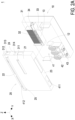
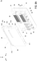
FIG. 1 is a perspective structural view illustrating a photovoltaic-inverter heat-dissipation assembly according to a first embodiment of the present disclosure; -
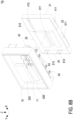
FIGS. 2A and2B are exploded views illustrating the photovoltaic-inverter heat-dissipation assembly according to the first embodiment of the present disclosure; -
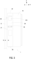
FIG. 3 is a lateral view illustrating the photovoltaic-inverter heat-dissipation assembly mounted on a wall according to the first embodiment of the present disclosure; -
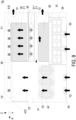
FIG. 4 is a schematic diagram showing the flow directions of the airflows in the rear chamber of the photovoltaic-inverter heat-dissipation assembly according to the first embodiment of the present disclosure; -
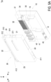
FIGS. 5A and5B are exploded views illustrating a photovoltaic-inverter heat-dissipation assembly according to a second embodiment of the present disclosure; -
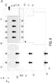
FIG. 6 is a schematic diagram showing the flow directions of the airflows in the rear chamber of the photovoltaic-inverter heat-dissipation assembly according to the second embodiment of the present disclosure; -
FIG. 7 is a perspective structural view illustrating a photovoltaic-inverter heat-dissipation assembly according to a third embodiment of the present disclosure; -
FIGS. 8A and8B are exploded views illustrating the photovoltaic-inverter heat-dissipation assembly according to the third embodiment of the present disclosure; -
FIG. 9 is a schematic diagram showing the flow directions of the airflows in the rear chamber of the photovoltaic-inverter heat-dissipation assembly according to the third embodiment of the present disclosure; -
FIGS. 10A and10B are exploded views illustrating a photovoltaic-inverter heat-dissipation assembly according to a fourth embodiment of the present disclosure; and -
FIG. 11 is a schematic diagram showing the flow directions of the airflows in the rear chamber of the photovoltaic-inverter heat-dissipation assembly according to the fourth embodiment of the present disclosure. - The present disclosure will now be described more specifically with reference to the following embodiments. It is to be noted that the following descriptions of preferred embodiments of this disclosure are presented herein for purpose of illustration and description only. It is not intended to be exhaustive or to be limited to the precise form disclosed. For example, the formation of a first feature over or on a second feature in the description that follows may include embodiments in which the first and second features are formed in direct contact, and may also include embodiments in which additional features may be formed between the first and second features, such that the first and second features may not be in direct contact. In addition, the present disclosure may repeat reference numerals and/or letters in the various examples. This repetition is for the purpose of simplicity and clarity and does not in itself dictate a relationship between the various embodiments and/or configurations discussed. Further, spatially relative terms, such as "top," "bottom," "front," "rear" and the like, may be used herein for ease of description to describe one element or feature's relationship to another element(s) or feature(s) as illustrated in the figures. The spatially relative terms are intended to encompass different orientations of the device in use or operation in addition to the orientation depicted in the figures. The apparatus may be otherwise oriented (rotated 90 degrees or at other orientations) and the spatially relative descriptors used herein may likewise be interpreted accordingly. When an element is referred to as being "connected," or "coupled," to another element, it can be directly connected or coupled to the other element or intervening elements may be present. Although the wide numerical ranges and parameters of the present disclosure are approximations, numerical values are set forth in the specific examples as precisely as possible. In addition, although the "first," "second," "third," and the like terms in the claims be used to describe the various elements can be appreciated, these elements should not be limited by these terms, and these elements are described in the respective embodiments are used to express the different reference numerals, these terms are only used to distinguish one element from another element. For example, a first element could be termed a second element, and, similarly, a second element could be termed a first element, without departing from the scope of example embodiments.
- Please refer to
FIG. 1 to FIG. 4 . A photovoltaic-inverter heat-dissipation assembly is illustrated according to a first embodiment of the present disclosure. In the embodiment, the photovoltaic-inverter heat-dissipation assembly 1 is provided and includes a front housing-base 10, arear cover 20, a first heat-generatingdevice 32, afirst fan 33, a second heat-generatingdevice 42 and asecond fan 43. The front housing-base 10 includes afront chamber 11, arear mounting surface 12 and apartition element 13. In the embodiment, thepartition element 13 is disposed on therear mounting surface 12. Therear cover 20 is combined with thepartition element 13 and therear mounting surface 12 of the front housing-base 10 to form a first heat-dissipation space 31 and a second heat-dissipation space 41 separated from each other. In the embodiment, therear cover 20 includes a first air-inlet 311, a second air-inlet 411 and at least one air-outlet. The first air-inlet 311 and the second air-inlet 411 are disposed separately from each other. Preferably but not exclusively, the at least one air-outlet includes a first air-outlet 312 and a second air-outlet 412 spatially corresponding to the first heat-dissipation space 31 and the second heat-dissipation space 41, respectively. In the embodiment, the first air-inlet 311 is in communication with the first air-outlet 312 through the first heat-dissipation space 31, and the second air-inlet 411 is in communication with the second air-outlet 412 through the second heat-dissipation space 41. In addition, the first heat-generatingdevice 32 is disposed on therear mounting surface 12 of the front housing-base 10 and accommodated in the first heat-dissipation space 31. Thefirst fan 33 is disposed adjacent to the first air-inlet 311, located between the first air-inlet 311 and the first heat-generatingdevice 32, and configured to generate a first airflow F1. Preferably but not exclusively, the first airflow F1 enters the first heat-dissipation space 311 through the first air-inlet 311, flows through the first heating-generatingdevice 32, and flows out through the first air-outlet 312. The second heat-generatingdevice 42 is disposed on therear mounting surface 12 of the front housing-base 10 and accommodated in the second heat-dissipation space 41. Thesecond fan 43 is disposed adjacent to the second air-inlet 411, located between the second air-inlet 411 and the second heat-generatingdevice 42, and configured to generate a second airflow F2. Preferably but not exclusively, the second airflow F2 enters the second heat-dissipation space 41 through the second air-inlet 411, flows through the second heat-generatingdevice 42, and flows out through the second air-outlet 412. - In the embodiment, the
rear cover 20 includes abackbone 21 spatially corresponding therear mounting surface 12 of the front housing-base 10. to a wall plane, and the photovoltaic-inverter heat-dissipation assembly is hung on the wall plane through the backbone. Preferably but not exclusively, thebackbone 21 is connected to the outer periphery of therear mounting surface 12 of the front housing-base 10 through atop plane 22, abottom plane 23 and alateral plane 24 of therear cover 20. In addition, thebackbone 21 of therear cover 20 is spatially corresponding to awall plane 9. The photovoltaic-inverter heat-dissipation assembly 1 is hung and fixed on thewall plane 9 through thebackbone 21 for use. In the embodiment, the first air-inlet 311 is disposed on thebackbone 21 of therear cover 20. The second air-inlet 411 is disposed on thebottom plane 23 of therear cover 20. Notably, when the front housing-base 10 and therear cover 20 of the photovoltaic-inverter heat-dissipation assembly 1 of the present disclosure, the space of the rear chamber between the front housing-base 10 and therear cover 20 is further divided according to the design of thepartition element 13, and divided into at least two independent spaces, such as the first heat-dissipation space 31 and the second heat-dissipation space 41 which are isolated from each other. The first heat-dissipation space 31 has thefirst fan 33 and the first air-inlet 311 disposed independently thereon, and the second heat-dissipation space 41 has thesecond fan 43 and the second air-inlet 411 disposed independently thereon. The first air-inlet 311 in communication with to the first heat-dissipation space 31 is disposed on thebackbone 21. Preferably but not exclusively, the first air-inlet 311 has an opening direction along the reverse Y axial direction. The second air-inlet 411 in communication with the second heat-dissipation space 41 is disposed on thebottom plane 23. Preferably but not exclusively, the second air-inlet 411 has an opening direction the reverse Z axial direction. - In the embodiment, when the
first fan 33 corresponding to the first heat-dissipation space 31 is activated, the first airflow F1 generated enters the firstheat dissipation space 31 through the first air-inlet 311 along the Y axial direction, then the first airflow F1 flows through the first heat-generatingdevice 32 along the Z axial direction, and finally the first airflow F1 flows out through the first air-outlet 312 along the reverse Y axial direction. In addition, when thesecond fan 43 corresponding to the second heat-dissipation space 41 is activated, the second airflow F2 generated enters the second heat-dissipation space 41 through the second air-inlet 411 along the Z axial direction, then the second airflow F2 flows through the second heat-generatingdevice 42 along the Z axial direction, and finally the second airflow F2 flows out through the second air-outlet 412 along the direction reverse Y axial direction. In the embodiment, the discharging flow directions (i.e., the reverse Y axial direction) of the first airflow F1 at the first air-outlet 312 and the second airflow F2 at the second air-outlet 412 are the same, but different from the suction flow direction (i.e., the Y axial direction) of the first airflow F1 at the first air-inlet 311. Moreover, the discharging flow directions (i.e., the reverse Y axial direction) of the first airflow F1 at the first air-outlet 312 and the second airflow F2 at the second air-outlet 412 are different from the suction flow direction (i.e., the Z axial direction) of the second airflow F2 at the second air-inlet 411. Furthermore, the opening direction of the first air-inlet 311 and the opening direction of the second air-inlet 411 are different. In this way, it facilitates to reduce the interference of thefirst airflow F 1 and the second airflow F2 during inflow. Thus, the stability of the air intake of each independent airflow is maintained. - In the embodiment, the
rear cover 20 further includes an auxiliary air-outlet 313 arranged on thelateral plane 24 of therear cover 20, and disposed adjacent to thetop plane 22 of therear cover 20. Preferably but not exclusively, the first air-inlet 311 is located between the auxiliary air-outlet 313 and the second air-inlet 411. After dissipating the heat of the first heat-generatingdevice 32 and the second heat-generatingdevice 42, the first airflow F1 and the second airflow F2 are discharged out through the first air-outlet 312, the second air-outlet 412 and the auxiliary air-outlet 313. The heat-dissipation performance of the first airflow F1 acting on the first heat-generatingdevice 32 and the heat-dissipation performance of the second airflow F2 acting on the second heat-generatingdevice 42 are not affected. Moreover, in the embodiment, thefirst fan 33 includes a plurality offirst fans 33, which are arranged in a row, detachably disposed therear cover 20 through anopening 314 on thelateral plane 24, and located between the first air-inlet 311 and the first-heat dissipation space 31. Thefirst fans 33 arranged in the row further include ahandle 34 disposed on one side of the plurality offirst fans 33, so as to facilitate the user to install or remove thefirst fans 33. Certainly, the present disclosure is not limited thereto. - In the embodiment, the
rear cover 20 further includes a retainingwall 25, which is arranged outside thebackbone 21. Preferably but not exclusively, the retainingwall 25 is extended laterally along the X axial direction between the twolateral planes 24, and configured to connect to thewall plane 9 in a direction (i.e., the reverse Y axial direction) from thebackbone 21 toward thewall plane 9. In the embodiment, the at least one air-outlet is disposed on thebackbone 21 and includes a first air-outlet 312 and a second air-outlet 412 extended along the X axial direction and adjacent to thetop plane 23 of therear cover 20. Preferably but not exclusively, the first air-outlet 312 and the second air-outlet 412 are in communication with each other. In other embodiments, the first air-outlet 312 and the second air-outlet 412 are connected and integrally formed into one piece, extended along the X axial direction and arranged adjacent to thetop plane 23. The type of the at least one air-out in the present disclosure is adjustable according to the practical requirements, and not limited thereto. Notably, the retainingwall 25 disposed outside thebackbone 21 is located between the first air-outlet 312, the second air-outlet 412 and the first air-inlet 311, so as to provide a function of compartmentalizing airflow. - In the embodiment, since the structure of retaining
wall 25 is disposed between the first air-inlet 311 and the first air-outlet 312 and between the second air-inlet 411 and the second air-outlet 412, when photovoltaic-inverter heat-dissipation assembly 1 is connected and fixed to thewall plane 9 through the retainingwall 25, thebackbone 21 and thewall plane 9 are arranged parallel to each other, and a spaced distance D, such as 40 mm, is maintained between thebackbone 21 and thewall plane 9. In that, a sufficient space is provided between thebackbone 21 and thewall plane 9 for air flow. Moreover, the structure of the retainingwall 25 is located between the first air-outlet 312 and the first air-inlet 311 and between the second air-outlet 412 and the second air-inlet 411, and it facilitates to prevent the airflow flowing through the upper air-outlet from flowing back to the lower air-inlet. In other words, cooperating with the retainingwall 25 arranged between the first air-outlet 312 and the first air-inlet 311 and between the second air-outlet 412 and the second air-inlet 411, the interference of the airflow is reduced, and the generation of heat-dissipation air backflow is avoided, so as to achieve the optimization of each independent airflow. - In the embodiment, the front housing-
base 10 further includes afront chamber 11, and therear mounting surface 12 is located between thefront chamber 11 and thepartition element 13. Preferably but not exclusively, the first heat-generatingdevice 32 is a first heat sink thermally coupled to the active component, such as aninverter module 320 accommodated in thefront chamber 11, through therear mounting surface 12. Preferably but not exclusively, the second heat-generating device 42 a choke device, such as an inverter choke. It should be noted that the heat-generating device mentioned in the present disclosure is not limited to generation through heat-transfer or self-heating, but refers to a heat-generating device that requires heat dissipation. The present disclosure is not limited thereto and not redundantly described herein. In the embodiment, since the heat of the first heat-generatingdevice 32 and the second heat-generatingdevice 42 is independently dissipated through the first heat-dissipatingspace 31 and the second heat-dissipatingspace 41 respectively, it helps to exert the best heat-dissipating performance. In other embodiments, thefront chamber 11 of the front housing-base 10 is used to accommodate the active components or the passive components with the requirements of waterproof and dustproof, and the active components or the passive components are further thermally coupled to the heat sink accommodated in the rear chamber to dissipate heat through the airflow. On the other hand, the active components or the passive components without the requirements of waterproof and dustproof are accommodated in the rear chamber to dissipate the heat through the airflow. Certainly, the arrangement of the first heat-generatingdevice 32 and the second heat-generatingdevice 42 are adjustable according to the practical requirements. The present disclosure is not limited thereto. -
FIG. 5A ,FIG. 5B andFIG. 6 illustrate a photovoltaic-inverter heat-dissipation assembly according to a second embodiment of the present disclosure. In the embodiment, the structures, elements and functions of the photovoltaic-inverter heat-dissipation assembly 1a are similar to those of the photovoltaic-inverter heat-dissipation assembly 1 ofFIG. 1 to FIG. 4 , and are not redundantly described herein. Different from the first embodiment where the second heat-generatingdevice 42 is disposed on a lower portion of the second heat-dissipation space 41, in the embodiment, the second heat-generatingdevice 42 is disposed on a upper portion of the second-heat dissipation space 41, located adjacent to thetop plane 22 and the second air-outlet 412 of therear cover 20, and arranged with the first heat-generatingdevice 32 side by side. The lower space of therear cover 20 can be used for arranging other device or be omitted, so as to improve the overall power density. Preferably but not exclusively, in the embodiment, the first heat-generatingdevice 32 is a heat sink and thermally coupled to aninverter module 320 accommodated in thefront chamber 11 through therear mounting surface 12. Preferably but not exclusively, the second heat-generatingdevice 42 is a choke device, such as an inverter choke. Since the first heat-dissipation space 31 and the second heat-dissipation space 4241 are independent and separated from each other, the first heat-generatingdevice 31 and the second heat-generating device 4142 can be arranged correspondingly and accommodated, respectively, to achieve the best heat dissipation performance and improve the overall power density at the same time. Certainly, the present disclosure is not limited thereto. -
FIG. 7 to FIG. 9 illustrate a photovoltaic-inverter heat-dissipation assembly according to a third embodiment of the present disclosure. In the embodiment, the structures, elements and functions of the photovoltaic-inverter heat-dissipation assembly 1a are similar to those of the photovoltaic-inverter heat-dissipation assembly 1 ofFIG. 1 to FIG. 4 , and are not redundantly described herein. In the embodiment, the photovoltaic-inverter heat-dissipation assembly 1b further includes a third heat-generating device, such as asecond heat sink 52 and aboost choke 54, and athird fan 53. Therear cover 20 is combined with thepartition element 13 and therear mounting surface 12 of the front housing-base 10 to form a first heat-dissipation space 31, a second heat-dissipation space 41 and a third heat-dissipation space 51, which are separated from each other. The first air-inlet 311 is disposed between the first heat-dissipation space 31 and the third heat-dissipation space 51. In addition, the first air-inlet 311 and the third heat-dissipation space 51 are isolated from each other and not in communication with each other. In the embodiment, therear cover 20 further includes a third air-inlet 511 and a third air-outlet 512. Thesecond heat sink 52 and theboost choke 54 served as the third heat-generating device are disposed on therear mounting surface 12 and accommodated in the third heat-dissipation space 51. Thethird fan 53 is disposed adjacent to the third air-inlet 511, located between the third air-inlet 511 and the third heat-generating device, and configured generate a third airflow F3, which enters the third heat-dissipation space 51 through the third air-inlet 511, flows through the third heat-generating device, and flows out through the third air-outlet 512. - In the embodiment, the first heat-
dissipation space 31, the second heat-dissipation space 41 and the third heat-dissipation space 51 are three independent heat-dissipation spaces, and the first heat-generatingdevice 32, the second heat-generatingdevice 42 and the third heat-generating device are accommodated in three independent heat-dissipation spaces, respectively. For the arrangement of many active components and passive components in the solar photovoltaic, the first heat-generatingdevice 32 is for example but not limited to the first heat sink accommodated in the first heat-dissipation space 31, and thermally coupled to aninverter module 320 accommodated in thefront chamber 11 through therear mounting surface 12. The second heat-generatingdevice 42 is for example but not limited to a choke device such as an inverter choke, disposed on therear mounting surface 12 and accommodated in the second heat-dissipation space 41. In addition, the active components such as the boost module, IGBT, and MOSFETF semiconductor switching device, or the passive components such as the capacitor, the boost choke and the resistor required by the photovoltaic inverters can be regarded as the third heat-generating device and arranged in to the third heat-dissipation space 51 correspondingly. Preferably but not exclusively, in the embodiment, the electronic components of thebooster module 520 is installed in thefront chamber 11 of the front housing-base 10 due to the requirement of waterproof and dustproof, and is thermally coupled to thesecond heat sink 52 through therear mounting surface 12, so as to dissipate the heat through the third airflow F3. In addition, theboost choke 54 can also be accommodated in the third heat-dissipation space 51 to dissipate the heat through the third airflow F3. When thefirst fan 33 corresponding to the first heat-dissipation space 31 is activated, the first airflow F1 generated enters the first heat-dissipation space 31 through the first air-inlet 311 along the Y axial direction, then the first airflow F1 flows through the first heat-generatingdevice 32 along the Z axial direction, and finally the first airflow F1 flows out through the first air-outlet 312 along the reverse Y axial direction. When thesecond fan 43 corresponding to the second heat-dissipation space 41 is activated, the second airflow F2 generated enters the second heat-dissipation space 41 through second air-inlet 411 along the Z axial direction, then the second airflow F2 flows through the second heat-generatingdevice 42 along the Z axial direction, and finally the second airflow F2 flows out through the second air-outlet 412 along the reverse Y axial direction. Moreover, when thethird fan 53 corresponding to the third heat-dissipation space 51 is activated, the third airflow F3 generated enters the third heat-dissipation space 51 through the third air-inlet 511 along the Z axial direction, then the third airflow F3 flows through the third heat-generating device such as thesecond heat sink 52 and theboost choke 54, and finally the third airflow F3 flows out through the third air-outlet 512 along the reverse X axial direction. The first airflow F1, the second airflow F2 and the third airflow F3 are independent, and the first airflow F1 and the third airflow F3 are more completely isolated and do not interfere with each other. In the embodiment, the second heat-dissipation space 41 is partially in communication with the third heat-dissipation space 51, and the second airflow F2 that completes the heat dissipation of the second heat-generatingdevice 42 and the third airflow F3 that completes the heat dissipation of the third heat-generating device are partially mixed. Then, the mixed airflow is discharged from the second air-outlet 412 without affecting the heat dissipation performance of the second airflow F2 acted on the second heat-generatingdevice 42 or the heat dissipation performance of the third airflow F3 acted on the third heat-generating device. -
FIG. 10A ,FIG. 10B andFIG. 11 illustrate a photovoltaic-inverter heat-dissipation assembly according to a fourth embodiment of the present disclosure. In the embodiment, the structures, elements and functions of the photovoltaic-inverter heat-dissipation assembly 1c are similar to those of the photovoltaic-inverter heat-dissipation assembly 1b ofFIG. 7 to FIG. 9 , and are not redundantly described herein. Preferably but not exclusively, in the embodiment, the first heat-generatingdevice 32 is a first heat sink and thermally coupled to aninverter module 320 accommodated in thefront chamber 11 through therear mounting surface 12. Preferably but not exclusively, the second heat-generatingdevice 42 is a choke device of an inverter choke, which is accommodated in the second heat-dissipation space 41 and disposed adjacent to thetop plane 22 and the second air-outlet 412 of therear cover 20. The second heat-generatingdevice 42 accommodated in the second heat-dissipation space 41 and the first heat-generatingdevice 32 accommodated in the first heat-dissipation space 31 are separated from each other left and right. Preferably but not exclusively, the third heat-generating device includes asecond heat sink 52 and aboost choke 54. The third heat-generating device accommodated in the third heat-dissipation space 41 and the first heat-generatingdevice 31 accommodated in the first heat-dissipation space 31 are isolated from each other up and down. The opening direction of the third air-outlet 512 is different from the opening direction of the first air-inlet 311 and also different from the opening direction of the second air-inlet 411. In this way, it is helpful to avoid the backflow of airflow for heat dissipation. Similarly, with the retainingwall 25 arranged between the first air-outlet 312 and the first air-inlet 311 and between the second air-outlet 412 and the second air-inlet 411, it also helps to reduce the interference of the airflows. At the same time, the generation of hot air backflow is avoided, and the optimization of each independent airflow is achieved. - Notably, in the present disclosure, when the front housing-
base 10 and therear cover 20 of the photovoltaic-inverter heat-dissipation assembly 1 are assembled, the space between the front housing-base 10 and therear cover 20 is divided according to the design of thepartition element 13. The rear chamber is divided into at least two heat-dissipation spaces that are isolated from each other. Preferably but not exclusively, the space is divided to form a horizontal isolation of the first heat-dissipation space 31 and the second heat-dissipation space 41, or the vertical isolation of the first heat-dissipation space 31 and the third heat-dissipation space 51. The arrangement of the isolated heat-dissipation spaces is adjustable according to the practical requirements. Each isolated heat dissipation space has an independent fan and an independent air-inlet. Cooperating with the adjustment of the opening directions of the air-inlet and air-outlet and the design of the retaining wall, the interference between the independent airflows is reduced and the backflow is avoided. On the other hand, for the main heat-generating devices such as the inverter module, the boost module, the inverter choke and the boost choke in the photovoltaic inverter, it allows to arrange them in at least two heat dissipation spaces divided from the rear chamber according to the heat dissipation requirements. The independent airflow in each heat-dissipation space is used to dissipate the heat, so that the occurrence of hot air dissipation or hot air backflow is avoided, the overall efficiency of heat-dissipation effectively is improved effectively, and the optimization of heat dissipation performance is achieved. Certainly, the arrangement of the heat-generating devices is not limited to the illustrated embodiments, and not redundantly described hereafter. - In summary, the present disclosure provides a photovoltaic-inverter heat-dissipation assembly. By assembling the front housing-base with the rear cover, the internal space of the rear chamber is divided into at least two heat-dissipation spaces, which are capable of dissipating the heat source through the independent airflow, respectively, so as to provide the better heat-dissipation performance, avoid the generation of hot air backflow from affecting the overall heat-dissipation performance. Each of the at least two heat-dissipation space has an independent fan and an independent air-inlet correspondingly disposed therein, so that at least two independent airflows are formed to effectively dissipate at least two heat-generating devices, respectively. The airflows for heat-dissipating in the at least two heat-dissipation space do not interfere with each other. After completing the heat-dissipation actions, the at least two independent airflows are discharged through at least one air-outlet on the top side, respectively, so as to exert a good heat-dissipation effect effectively. The space of the rear chamber is divided into at least two heat-dissipation spaces, which are isolated from each other, and include an independent fan and an independent air-inlet, respectively. The openings of the air-inlets of the at least two heat-dissipation spaces face different directions, so that the mutual interference is reduced and the stability of the independent airflow flowing through the corresponding air-inlet is maintained. In addition, the flow directions of the independent airflows at the air-outlets are also different from the flow directions of the independent airflows at the corresponding air-inlets. Cooperating with the retaining wall arranged between at least one air-outlet and each air-inlet, the interference of the airflow is reduced, and the generation of heat-dissipation air backflow is avoided at the same time, so as to achieve the optimization of each independent airflow. On the other hand, since the retaining wall is arranged between at least one air-outlet and the air-inlets, when the photovoltaic-inverter heat-dissipation assembly is fixed to a wall through the retaining wall and maintains a spaced distance, a sufficient space between the back panel and the wall is provided for air flow. Moreover, the retaining wall structure is located between the air-outlet and the air-inlet, and it facilitates to prevent the airflow flowing through the upper air-outlet from flowing back to the lower air-inlet. It allows to arrange the active components such as the boost module, the inverter module, IGBT, MOSFETF semiconductor switching devices or the passive components such as the capacitors, the boost choke, the inverter choke and the resistors of the PV inverter in the at least two heat-dissipation spaces according to the actual heat-dissipation requirements, so as to exert the best heat-dissipation performance. The active components or the passive components with the requirements of waterproof and dustproof are accommodated in the front chamber and thermally coupled to the heat sink in the rear chamber, so as to dissipate the heat through the airflow. The active components or the passive components without the requirements of waterproof and dustproof are accommodated in the rear chamber to dissipate the heat through the airflow. In other words, the at least two heat-dissipation spaces divided from the rear chamber are configured to accommodate different sets of heat sinks or chokes, and the independent airflow in each heat-dissipation space is used to dissipate the heat, so that the occurrence of hot air dissipation or hot air backflow is avoided, and the overall efficiency of heat-dissipation effectively is improved effectively.
Claims (15)
- A photovoltaic-inverter heat-dissipation assembly (1, 1a, 1b, 1c) characterized by comprising:a front housing-base (10) comprising a rear mounting surface (12) and a partition element (13), wherein the partition element (13) is disposed on the rear mounting surface (12);a rear cover (20) combined with the partition element (13) and the rear mounting surface (12) of the front housing-base (10) to form a first heat-dissipation space (31) and a second heat-dissipation space (41) separated from each other, and comprising a first air-inlet (311), a second air-inlet (411) and at least one air-outlet (312, 412), wherein the first air-inlet (311) and the second air-inlet (411) are in communication with the at least one air-outlet (312, 412) through the first heat-dissipation space (31) and the second heat-dissipation space (41), respectively;a first heat-generating device (32) disposed on the rear mounting surface (12), and accommodated in the first heat-dissipation space (31);a first fan (33) disposed adjacent to the first air-inlet (311), located between the first air-inlet (311) and the first heat-generating device (31), and configured to generate a first airflow (F1), which enters through the first air-inlet (311), flows through the first heating-generating device (32), and flows out through the at least one air-outlet (312);a second heat-generating device (42) disposed on the rear mounting surface (12), and accommodated in the second heat-dissipation space (41); anda second fan (43) disposed adjacent to the second air-inlet (411), located between the second air-inlet (411) and the second heat-generating device (42), and configured to generate a second airflow (F2), which enters through the second air-inlet (411), flows through the second heat-generating device (42), and flows out through the at least one air-outlet (412).
- The photovoltaic-inverter heat-dissipation assembly (1, 1a, 1b, 1c) according to claim 1, wherein the rear cover (20) comprises a backbone (21) spatially corresponding to a wall plane (9), and the photovoltaic-inverter heat-dissipation assembly (1, 1a, 1b, 1c) is hung on the wall plane (9) through the backbone (21).
- The photovoltaic-inverter heat-dissipation assembly (1, 1a, 1b, 1c) according to claim 2, wherein the rear cover (20) comprises a retaining wall (25) arranged outside the backbone (21), extended laterally, and configured to connect to the wall plane (9) in a direction from the backbone (21) toward the wall plane (9).
- The photovoltaic-inverter heat-dissipation assembly (1, 1a, 1b, 1c) according to claim 3, wherein the at least one air-outlet (312, 412) is arranged on the backbone (21) and disposed adjacent to a top plane (22) of the rear cover (20), wherein the first air-inlet (311) is arranged on the backbone (21).
- The photovoltaic-inverter heat-dissipation assembly (1, 1a, 1b, 1c) according to claim 4, wherein the second air-inlet (411) is disposed on a bottom plane (23) of the rear cover (20).
- The photovoltaic-inverter heat-dissipation assembly (1, 1a, 1b, 1c) according to claim 3, wherein the backbone (21) and the wall plane (9) are arranged parallel to each other, and connected to each other through the retaining wall (25), and a spaced distance (D) is maintained between the backbone (21) and the wall plane (9).
- The photovoltaic-inverter heat-dissipation assembly (1, 1a, 1b, 1c) according to claim 1, wherein the at least one air-outlet (312 412) comprises a first air-outlet (312) and a second air-outlet (412) spatially corresponding to the first heat-dissipation space (31) and the second heat-dissipation space (41), respectively, and disposed adjacent to a top plane (22) of the rear cover (20).
- The photovoltaic-inverter heat-dissipation assembly (1, 1a, 1b, 1c) according to claim 7, wherein the rear cover (20) further comprises an auxiliary air-outlet (313) arranged on a lateral plane (24) of the rear cover and disposed adjacent to the top plane (22) of the rear cover (20).
- The photovoltaic-inverter heat-dissipation assembly (1, 1a, 1b, 1c) according to claim 8, wherein the first fan (33) is detachably disposed on the rear cover (20) through an opening (314) on the lateral plane (24), and located between the first air-inlet (311) and the first heat-dissipation space (31).
- The photovoltaic-inverter heat-dissipation assembly (1b, 1c) according to claim 7, further comprising a third heat-generating device and a third fan (53), wherein the rear cover (20) is combined with the partition element (13) and the rear mounting surface (12) of the front housing-base (10) to form the first heat-dissipation space (31), the second heat-dissipation space (41) and a third heat-dissipation space (51) separated from each other, the first air-inlet (311) is arranged between the first heat-dissipation space (31) and the third heat-dissipation space (51), the first air-inlet (311) and the third heat-dissipation space (51) are isolated from each other, and the rear cover (20) further comprises a third air-inlet (511) and a third air-outlet (512), wherein the third heat-generating device is disposed on the rear mounting surface (12) and accommodated in the third heat-dissipation space (51), wherein the third fan (53) is disposed adjacent to the third air-inlet (511), located between the third air-inlet (511) and the third heat-generating device (51), and configured to generate a third airflow (F3), which enters through the third air-inlet (511), flows through the third heat-generating device, and flows out through the third air-outlet (512).
- The photovoltaic-inverter heat-dissipation assembly (1b, 1c) according to claim 10, wherein the third air-inlet (511) is disposed on a bottom plane (23) of the rear cover (20), and separated from the second air-inlet (411), and the third heat-dissipation space (51) is located between the third air-outlet (512) and the second heat-dissipation space (41).
- The photovoltaic-inverter heat-dissipation assembly (1b, 1c) according to claim 10, wherein the front housing-base (10) further comprises a front chamber (11), the rear mounting surface (12) is located between the front chamber (11) and the partition element (13), the first heat-generating device (32) comprises a first heat sink, and the first heat sink is thermally coupled to an inverter module (320) accommodated in the first chamber (11) through the rear mounting surface (12), wherein the second heat-generating device (42) comprises an inverter choke, the third heat-generating device comprises a second heat sink (52) and a boost choke (54), and the second heat sink (52) is thermally coupled to a booster module (520) accommodated in the first chamber (11) through the rear mounting surface (12).
- The photovoltaic-inverter heat-dissipation assembly (1, 1a, 1b, 1c) according to claim 1, wherein an opening direction of the first air-inlet (311) and an opening direction of the second air-inlet (411) are different from each other.
- The photovoltaic-inverter heat-dissipation assembly (1, 1a, 1b, 1c) according to claim 1, wherein the first airflow (F1) and the second airflow (F2) have a flow direction at the at least one air-outlet (312, 412) different from a flow direction of the first airflow (F1) at the first air-inlet (311), and different from a flow direction of the second airflow (F2) at the second air-inlet (411).
- The photovoltaic-inverter heat-dissipation assembly (1, 1a, 1b, 1c) according to claim 1, wherein the front housing-base (10) further comprises a front chamber (11), the rear mounting surface (12) is located between the front chamber (11) and the partition element (13), the first heat-generating device (32) and the second heat-generating device (42) comprise a heat sink and a choke device, respectively, the heat sink is thermally coupled to an active component or a passive component accommodated in the first chamber (11) through the rear mounting surface (12), and the choke device is a boost choke (54) or an inverter choke.
Applications Claiming Priority (1)
| Application Number | Priority Date | Filing Date | Title |
|---|---|---|---|
| CN202310549487.8A CN119012612A (en) | 2023-05-16 | 2023-05-16 | Radiating assembly structure of sunlight inverter |
Publications (2)
| Publication Number | Publication Date |
|---|---|
| EP4465779A1 true EP4465779A1 (en) | 2024-11-20 |
| EP4465779B1 EP4465779B1 (en) | 2026-03-18 |
Family
ID=87196395
Family Applications (1)
| Application Number | Title | Priority Date | Filing Date |
|---|---|---|---|
| EP23184141.2A Active EP4465779B1 (en) | 2023-05-16 | 2023-07-07 | Photovoltaic-inverter heat-dissipation assembly |
Country Status (3)
| Country | Link |
|---|---|
| US (1) | US12609652B2 (en) |
| EP (1) | EP4465779B1 (en) |
| CN (1) | CN119012612A (en) |
Families Citing this family (1)
| Publication number | Priority date | Publication date | Assignee | Title |
|---|---|---|---|---|
| USD1061439S1 (en) * | 2023-04-11 | 2025-02-11 | WeCo (Guangdong) Energy Storage Technology Co., Ltd. | Inverter |
Citations (5)
| Publication number | Priority date | Publication date | Assignee | Title |
|---|---|---|---|---|
| CN103260386A (en) * | 2013-05-15 | 2013-08-21 | 上海正泰电源系统有限公司 | Layout structure of high-power power electronic equipment |
| JP5730701B2 (en) * | 2011-07-25 | 2015-06-10 | 新電元工業株式会社 | Power conditioner device and photovoltaic power generation system |
| EP3668294A1 (en) * | 2018-12-10 | 2020-06-17 | Sungrow Power Supply Co., Ltd. | Power cabinet, grid-connected photovoltaic system and container |
| US20200367389A1 (en) * | 2019-05-14 | 2020-11-19 | Abb Schweiz Ag | Electrical apparatus |
| US20210391824A1 (en) * | 2020-06-15 | 2021-12-16 | Sungrow Power Supply Co., Ltd. | Photovoltaic Inverter |
Family Cites Families (7)
| Publication number | Priority date | Publication date | Assignee | Title |
|---|---|---|---|---|
| KR100445033B1 (en) | 2002-08-26 | 2004-08-18 | 삼성에스디아이 주식회사 | A case for covering electronic parts and a displaying apparatus having it |
| DE202009007413U1 (en) * | 2009-05-25 | 2009-08-20 | Sma Solar Technology Ag | Anti-theft device for an inverter |
| TWI505073B (en) | 2012-03-22 | 2015-10-21 | Compal Electronics Inc | Electronic device |
| TWI511655B (en) | 2013-03-14 | 2015-12-01 | Wistron Corp | Channel diversion device and related heat dissipating system |
| TWM493696U (en) | 2014-09-17 | 2015-01-11 | Antec Inc | Computer case having multiple independent wind flows |
| JP7047400B2 (en) | 2018-01-25 | 2022-04-05 | 富士電機株式会社 | Power converter |
| CN212677069U (en) | 2020-08-26 | 2021-03-09 | 深圳市英威腾光伏科技有限公司 | High-power photovoltaic group string type inverter |
-
2023
- 2023-05-16 CN CN202310549487.8A patent/CN119012612A/en active Pending
- 2023-07-07 EP EP23184141.2A patent/EP4465779B1/en active Active
- 2023-07-07 US US18/219,471 patent/US12609652B2/en active Active
Patent Citations (5)
| Publication number | Priority date | Publication date | Assignee | Title |
|---|---|---|---|---|
| JP5730701B2 (en) * | 2011-07-25 | 2015-06-10 | 新電元工業株式会社 | Power conditioner device and photovoltaic power generation system |
| CN103260386A (en) * | 2013-05-15 | 2013-08-21 | 上海正泰电源系统有限公司 | Layout structure of high-power power electronic equipment |
| EP3668294A1 (en) * | 2018-12-10 | 2020-06-17 | Sungrow Power Supply Co., Ltd. | Power cabinet, grid-connected photovoltaic system and container |
| US20200367389A1 (en) * | 2019-05-14 | 2020-11-19 | Abb Schweiz Ag | Electrical apparatus |
| US20210391824A1 (en) * | 2020-06-15 | 2021-12-16 | Sungrow Power Supply Co., Ltd. | Photovoltaic Inverter |
Also Published As
| Publication number | Publication date |
|---|---|
| CN119012612A (en) | 2024-11-22 |
| US20240388248A1 (en) | 2024-11-21 |
| US12609652B2 (en) | 2026-04-21 |
| EP4465779B1 (en) | 2026-03-18 |
Similar Documents
| Publication | Publication Date | Title |
|---|---|---|
| EP3668292B1 (en) | Inverter device having heat dissipation mechanism | |
| CN115413200B (en) | Power device and photovoltaic system | |
| JP4265505B2 (en) | Heat dissipation structure of electronic equipment | |
| WO2023143309A1 (en) | Heat dissipation system, power supply system, and charging pile | |
| CN212677069U (en) | High-power photovoltaic group string type inverter | |
| CN112311206B (en) | Heat exchange system and frequency converter | |
| US12609652B2 (en) | Photovoltaic-inverter heat-dissipation assembly | |
| JP4093479B2 (en) | Power supply | |
| CN118174515B (en) | Power conversion equipment and energy storage equipment | |
| CN215188051U (en) | Heat dissipation module, electronic equipment and energy storage equipment | |
| CN116232013B (en) | Inverter and electrical equipment | |
| CN110957775A (en) | A charging module and charging cabinet | |
| CN212970536U (en) | Converter modules and converter cabinets | |
| JPH07249885A (en) | Cooling structure | |
| CN206743092U (en) | High power density DC-to-DC power converter | |
| TWI847698B (en) | Photovoltaic-inverter heat-dissipation assembly | |
| CN118413979A (en) | Inverter | |
| CN112994329B (en) | Driving integrated double-effect cooling motor combined shell | |
| JP6575914B2 (en) | Power converter | |
| JP2019165549A (en) | Power conversion device and power storage system | |
| CN110225689A (en) | The radiator structure of electric component box | |
| CN111684209A (en) | Outdoor unit and air conditioner | |
| CN219181940U (en) | Heat abstractor and dc-to-ac converter of dc-to-ac converter | |
| CN219628226U (en) | Power inverter capable of improving heat dissipation efficiency | |
| CN222128573U (en) | A charging pile circuit board with heat dissipation structure |
Legal Events
| Date | Code | Title | Description |
|---|---|---|---|
| PUAI | Public reference made under article 153(3) epc to a published international application that has entered the european phase |
Free format text: ORIGINAL CODE: 0009012 |
|
| STAA | Information on the status of an ep patent application or granted ep patent |
Free format text: STATUS: REQUEST FOR EXAMINATION WAS MADE |
|
| 17P | Request for examination filed |
Effective date: 20240730 |
|
| AK | Designated contracting states |
Kind code of ref document: A1 Designated state(s): AL AT BE BG CH CY CZ DE DK EE ES FI FR GB GR HR HU IE IS IT LI LT LU LV MC ME MK MT NL NO PL PT RO RS SE SI SK SM TR |
|
| GRAP | Despatch of communication of intention to grant a patent |
Free format text: ORIGINAL CODE: EPIDOSNIGR1 |
|
| STAA | Information on the status of an ep patent application or granted ep patent |
Free format text: STATUS: GRANT OF PATENT IS INTENDED |
|
| INTG | Intention to grant announced |
Effective date: 20251008 |
|
| GRAS | Grant fee paid |
Free format text: ORIGINAL CODE: EPIDOSNIGR3 |
|
| GRAA | (expected) grant |
Free format text: ORIGINAL CODE: 0009210 |
|
| STAA | Information on the status of an ep patent application or granted ep patent |
Free format text: STATUS: THE PATENT HAS BEEN GRANTED |
|
| AK | Designated contracting states |
Kind code of ref document: B1 Designated state(s): AL AT BE BG CH CY CZ DE DK EE ES FI FR GB GR HR HU IE IS IT LI LT LU LV MC ME MK MT NL NO PL PT RO RS SE SI SK SM TR |
|
| REG | Reference to a national code |
Ref country code: CH Ref legal event code: F10 Free format text: ST27 STATUS EVENT CODE: U-0-0-F10-F00 (AS PROVIDED BY THE NATIONAL OFFICE) Effective date: 20260318 Ref country code: GB Ref legal event code: FG4D |
|
| REG | Reference to a national code |
Ref country code: DE Ref legal event code: R096 Ref document number: 602023013600 Country of ref document: DE |
|
| REG | Reference to a national code |
Ref country code: IE Ref legal event code: FG4D |