EP4465524A1 - System for estimating temperature of permanent magnet of rotor of motor - Google Patents
System for estimating temperature of permanent magnet of rotor of motor Download PDFInfo
- Publication number
- EP4465524A1 EP4465524A1 EP24173974.7A EP24173974A EP4465524A1 EP 4465524 A1 EP4465524 A1 EP 4465524A1 EP 24173974 A EP24173974 A EP 24173974A EP 4465524 A1 EP4465524 A1 EP 4465524A1
- Authority
- EP
- European Patent Office
- Prior art keywords
- temperature
- permanent magnet
- axis
- motor
- magnetic flux
- Prior art date
- Legal status (The legal status is an assumption and is not a legal conclusion. Google has not performed a legal analysis and makes no representation as to the accuracy of the status listed.)
- Granted
Links
Images



Classifications
-
- H—ELECTRICITY
- H02—GENERATION; CONVERSION OR DISTRIBUTION OF ELECTRIC POWER
- H02P—CONTROL OR REGULATION OF ELECTRIC MOTORS, ELECTRIC GENERATORS OR DYNAMO-ELECTRIC CONVERTERS; CONTROLLING TRANSFORMERS, REACTORS OR CHOKE COILS
- H02P29/00—Arrangements for regulating or controlling electric motors, appropriate for both AC and DC motors
- H02P29/60—Controlling or determining the temperature of the motor or of the drive
- H02P29/66—Controlling or determining the temperature of the rotor
- H02P29/662—Controlling or determining the temperature of the rotor the rotor having permanent magnets
-
- H—ELECTRICITY
- H02—GENERATION; CONVERSION OR DISTRIBUTION OF ELECTRIC POWER
- H02P—CONTROL OR REGULATION OF ELECTRIC MOTORS, ELECTRIC GENERATORS OR DYNAMO-ELECTRIC CONVERTERS; CONTROLLING TRANSFORMERS, REACTORS OR CHOKE COILS
- H02P21/00—Arrangements or methods for the control of electric machines by vector control, e.g. by control of field orientation
- H02P21/06—Rotor flux based control involving the use of rotor position or rotor speed sensors
-
- H—ELECTRICITY
- H02—GENERATION; CONVERSION OR DISTRIBUTION OF ELECTRIC POWER
- H02P—CONTROL OR REGULATION OF ELECTRIC MOTORS, ELECTRIC GENERATORS OR DYNAMO-ELECTRIC CONVERTERS; CONTROLLING TRANSFORMERS, REACTORS OR CHOKE COILS
- H02P21/00—Arrangements or methods for the control of electric machines by vector control, e.g. by control of field orientation
- H02P21/14—Estimation or adaptation of machine parameters, e.g. flux, current or voltage
-
- H—ELECTRICITY
- H02—GENERATION; CONVERSION OR DISTRIBUTION OF ELECTRIC POWER
- H02P—CONTROL OR REGULATION OF ELECTRIC MOTORS, ELECTRIC GENERATORS OR DYNAMO-ELECTRIC CONVERTERS; CONTROLLING TRANSFORMERS, REACTORS OR CHOKE COILS
- H02P2207/00—Indexing scheme relating to controlling arrangements characterised by the type of motor
- H02P2207/05—Synchronous machines, e.g. with permanent magnets or DC excitation
-
- Y—GENERAL TAGGING OF NEW TECHNOLOGICAL DEVELOPMENTS; GENERAL TAGGING OF CROSS-SECTIONAL TECHNOLOGIES SPANNING OVER SEVERAL SECTIONS OF THE IPC; TECHNICAL SUBJECTS COVERED BY FORMER USPC CROSS-REFERENCE ART COLLECTIONS [XRACs] AND DIGESTS
- Y10—TECHNICAL SUBJECTS COVERED BY FORMER USPC
- Y10S—TECHNICAL SUBJECTS COVERED BY FORMER USPC CROSS-REFERENCE ART COLLECTIONS [XRACs] AND DIGESTS
- Y10S388/00—Electricity: motor control systems
- Y10S388/90—Specific system operational feature
- Y10S388/902—Compensation
Definitions
- the present invention relates to a system for estimating a temperature of a permanent magnet of a rotor of a motor, and more specifically, to a system for estimating a temperature of a permanent magnet of a rotor for a motor, which may monitor the temperature of the permanent magnet attached to the rotor of the motor in real time.
- first method a method of assuming that a temperature of a stator coil and a temperature of a permanent magnet of a rotor are the same
- second method a method of estimating a temperature of a permanent of a rotor by generating a three-dimensional magnetic flux map for a speed, torque, and temperature of the rotor of a motor
- third method a method of estimating a temperature of a permanent magnet using a thermal resistance of a motor and the characteristics of a cooling system
- the first method among the above methods has a problem of low torque control precision because it is not based on the temperature of the permanent magnet of the rotor of the motor.
- the second method has a problem that a temperature estimation error increases according to a change in battery voltage (or a direct-current high voltage) because it does not consider a magnetic flux change according to a voltage change in a high-voltage battery.
- a four-dimensional magnetic flux map should be generated or three or more sets of three-dimensional magnetic flux maps should be generated, which has a problem that many CPU memories are occupied and it takes much time to develop the magnetic flux map.
- the third method may have the performance of the cooling system that changes according to a vehicle driving environment.
- thermal resistances of a rotor and a stator of the motor varies depending on a flow rate of a cooling medium.
- a system for estimating a temperature of a permanent magnet of a rotor of a motor including a first determination unit configured to determine whether a rotational speed of the rotor is greater than or equal to a reference speed, a second determination unit configured to determine a first condition, the first condition being whether a current flowing in a coil included in the motor is less than a reference current, and a second condition, the second condition being whether a magnitude of q-axis energy of the motor is less than a reference energy magnitude, when the rotational speed is greater than or equal to the reference speed, a magnetic flux map temperature estimation unit configured to estimate the temperature of the permanent magnet included in the rotor using a d-axis magnetic flux map of the motor responsive to one or more of the first condition and the second condition is satisfied in the second determination unit, and an energy map temperature estimation unit configured to estimate the temperature of the permanent magnet using a q-axis energy map of the motor responsive to one or more of the first condition and the second condition not being satisfied in the
- the magnetic flux map temperature estimation unit may include a first storage unit configured to store data on a d-axis current, q-axis current, and d-axis magnetic flux flowing in the coil of the motor for each temperature acquired through a previously performed test, a second storage unit configured to process the data stored in the first storage unit using a first-order equation of the d-axis magnetic flux to the temperature for each d-axis current and q-axis current, and to calculate data on a coefficient of a first-order term and a constant term for each d-axis current and q-axis current of the first-order equation, a first calculation unit configured to calculate a first corrected magnetic flux using the data stored in the second storage unit and an equation below, and a second calculation unit configured to remove errors from the first corrected magnetic flux and to calculate the estimated temperature of the permanent magnet, and when receiving a current command value of the motor, the first calculation unit inputs a coefficient of the first-order term and a constant term corresponding to the current command value and an estimated temperature of the
- the second calculation unit may include a reference magnetic flux generator configured to calculate a d-axis reference magnetic flux according to the current command value, a voltage command value, and an electric angular speed input into the motor, a first compensation value storage unit configured to store magnetic flux nonlinearity compensation value data for each DC input voltage, rotational speed, and torque of the motor and calculate a magnetic flux nonlinearity compensation value according to the DC input voltage, the rotational speed, and the torque of the motor, a first compensation applier configured to generate a second corrected magnetic flux by subtracting the magnetic flux nonlinearity compensation value from the d-axis reference magnetic flux and the first corrected magnetic flux, a first integral controller configured to receive and integrally control a value received from the first compensation applier, and a first temperature estimator configured to add a temperature measured value of the coil of the motor to an output of the first integral controller and to calculate the estimated temperature of the permanent magnet.
- a reference magnetic flux generator configured to calculate a d-axis reference magnetic flux according to the current command value, a voltage command
- the second calculation unit further may include a first output value limiter configured to filter the estimated temperature of the permanent magnet from the first temperature estimator or calculate the estimated temperature of the permanent magnet by limiting a change rate of the estimated temperature of the permanent magnet.
- a calculation of the magnetic flux nonlinearity compensation value data may include calculating a first d-axis magnetic flux according to the current command value, the voltage command value, and the electric angular speed input into the motor through a previously performed test, calculating a second d-axis magnetic flux by inputting an actually measured temperature of the permanent magnet into the first-order equation and inputting a coefficient of the first-order term and the constant term according to the d-axis current and q-axis current according to the current command value input into the motor and the actually measured temperature of the permanent magnet among the data stored in the second storage unit, and subtracting the second d-axis magnetic flux from the first d-axis magnetic flux.
- the energy map temperature estimation unit may include a third storage unit in which data on a d-axis current, q-axis current, and q-axis energy flowing in the coil of the motor for each temperature from a previously performed test is stored, a fourth storage unit configured to process the data stored in the third storage unit using a second-order equation of the q-axis energy to the temperature for each d-axis current and q-axis current, and to generate and store data on a coefficient of a second-order term, a coefficient of a first-order term, and a constant term for each d-axis current and q-axis current of the second-order equation, a third calculation unit configured to calculate a first corrected energy value using the data stored in the fourth storage unit and an equation below, and a fourth calculation unit configured to remove errors from the first corrected energy value and then calculate the estimated temperature of the permanent magnet, and when receiving a current command value of the motor, the third calculation unit inputs a coefficient of the second-order term, a coefficient of the first
- the fourth calculation unit may include a reference energy generator configured to calculate a q-axis reference energy according to the current command value, a voltage command value, and a speed input into the motor, a first compensation value storage configured to store energy nonlinearity compensation value data for each DC input voltage, rotational speed, and torque of the motor and calculate an energy nonlinearity compensation value according to the DC input voltage, the rotational speed, and the torque of the motor, a second compensation applier configured to generate second corrected energy by subtracting the energy nonlinearity compensation value from the q-axis reference energy and output the first corrected energy from the second corrected energy, a second integral controller configured to receive and integrally control an output value of the second compensation applier, and a second temperature estimator configured to add a temperature measured value of the coil of the motor to an output of the second integral controller and calculate the estimated temperature of the permanent magnet.
- a reference energy generator configured to calculate a q-axis reference energy according to the current command value, a voltage command value, and a speed input into the motor
- the fourth calculation unit further may include a second output value limiter configured to receive and filter the estimated temperature of the permanent magnet output from the second temperature estimator or to calculate the estimated temperature of the permanent magnet by limiting a change rate of the estimated temperature of the permanent magnet.
- a second output value limiter configured to receive and filter the estimated temperature of the permanent magnet output from the second temperature estimator or to calculate the estimated temperature of the permanent magnet by limiting a change rate of the estimated temperature of the permanent magnet.
- a calculation of the energy nonlinearity compensation value data may include calculating first q-axis energy according to the current command value, the voltage command value, and the electric angular speed input into the motor through a previously performed test, calculating second q-axis energy by inputting an actually measured temperature of the permanent magnet into the second-order equation and inputting a coefficient of the second-order term, a coefficient of the first-order term, and the constant term according to the d-axis current and q-axis current according to the current command value input into the motor and the actually measured temperature of the permanent magnet among the data stored in the fourth storage unit, and subtracting the second q-axis energy from the first q-axis energy.
- the system may include a basic permanent magnet temperature estimator configured to calculate a temperature measured value of a stator coil of the motor as the estimated temperature of the permanent magnet when the rotational speed of the rotor included in the motor is lower than the reference speed.
- a temperature estimation apparatus including one or more processors configured to execute instructions and a memory storing the instructions, wherein execution of the instructions configures the one or more processors to determine whether a rotational speed of a rotor of a motor is greater than or equal to a reference speed, determine a first condition, the first condition being whether a current flowing in a coil of the motor is less than a reference current, and a second condition, the second condition being whether a magnitude of q-axis energy of the motor is less than a reference energy magnitude, when the rotational speed is greater than or equal to the reference speed, estimate a magnetic flux map of the temperature of a permanent magnet of the rotor using a d-axis magnetic flux map of the motor responsive to one or more of the first condition and the second condition being satisfied, and estimate an energy map of the temperature of the permanent magnet using a q-axis energy map of the motor responsive to one or more of the first condition and the second condition not being satisfied.
- the processor may be further configured to calculate a d-axis reference magnetic flux according to the current command value, a voltage command value, and an electric angular speed input into the motor, store magnetic flux nonlinearity compensation value data for each DC input voltage, rotational speed, and torque of the motor and calculate a magnetic flux nonlinearity compensation value according to the DC input voltage, the rotational speed, and the torque of the motor, generate, via a first compensation applier, a second corrected magnetic flux by subtracting the magnetic flux nonlinearity compensation value from the d-axis reference magnetic flux and the first corrected magnetic flux, receive and integrally control a first value received from the first compensation applier, and add a temperature measured value of the coil of the motor to the first value and to calculate the estimated temperature of the permanent magnet.
- the processor may be further configured to filter the estimated temperature of the permanent magnet from or calculate the estimated temperature of the permanent magnet by limiting a change rate of the estimated temperature of the permanent magnet.
- a calculation of the magnetic flux nonlinearity compensation value data may include calculating a first d-axis magnetic flux according to the current command value, the voltage command value, and the electric angular speed input into the motor through a previously performed test, calculating a second d-axis magnetic flux by inputting an actually measured temperature of the permanent magnet into the first-order equation and inputting a coefficient of the first-order term and the constant term according to the d-axis current and q-axis current according to the current command value input into the motor and the actually measured temperature of the permanent magnet among the second data, and subtracting the second d-axis magnetic flux from the first d-axis magnetic flux.
- the estimation of the energy map may include storing third data on a d-axis current, q-axis current, and q-axis energy flowing in the coil of the motor for each temperature from a previously performed test is stored, processing the third data using a second-order equation of the q-axis energy to the temperature for each d-axis current and q-axis current, and to generate and store data on a coefficient of a second-order term, a coefficient of a first-order term, and a constant term for each d-axis current and q-axis current of the second-order equation, calculating a first corrected energy value using the fourth data and an equation below, and removing errors from the first corrected energy value and then calculate the estimated temperature of the permanent magnet, and, when receiving a current command value of the motor, inputting a coefficient of the second-order term, a coefficient of the first-order term, and a constant term corresponding to the current command value and an estimated temperature of the permanent magnet estimated before from among the fourth data into the equation, E
- the processor may be further configured to calculate a q-axis reference energy according to the current command value, a voltage command value, and a speed input into the motor, store energy nonlinearity compensation value data for each DC input voltage, rotational speed, and torque of the motor and calculate an energy nonlinearity compensation value according to the DC input voltage, the rotational speed, and the torque of the motor, generate, via a second compensation applier, second corrected energy by subtracting the energy nonlinearity compensation value from the q-axis reference energy and output the first corrected energy from the second corrected energy, receive and integrally control a second output value of the second compensation applier, and add a temperature measured value of the coil of the motor to the second output value and calculate the estimated temperature of the permanent magnet.
- the removing the errors from the first corrected energy may include filtering the estimated temperature of the permanent magnet or to calculate the estimated temperature of the permanent magnet by limiting a change rate of the estimated temperature of the permanent magnet.
- a calculation of the energy nonlinearity compensation value data may include calculating first q-axis energy according to the current command value, the voltage command value, and the electric angular speed input into the motor through a previously performed test, calculating second q-axis energy by inputting an actually measured temperature of the permanent magnet into the second-order equation and inputting a coefficient of the second-order term, a coefficient of the first-order term, and the constant term according to the d-axis current and q-axis current according to the current command value input into the motor and the actually measured temperature of the permanent magnet among the fourth data, and subtracting the second q-axis energy from the first q-axis energy.
- the processor may be further configured to calculate a temperature measured value of a stator coil of the motor as the estimated temperature of the permanent magnet when the rotational speed of the rotor included in the motor is lower than the reference speed.
- first, second, A, B, (a), (b) or the like may be used herein to describe components.
- Each of these terminologies is not used to define an essence, order or sequence of a corresponding component but used merely to distinguish the corresponding component from other component(s).
- a first component may be referred to as a second component, and similarly the second component may also be referred to as the first component.
- any one element in a case in which any one element is described as being formed on or under another element, such a description includes both a case in which the two elements are formed in direct contact with each other and a case in which the two elements are in indirect contact with each other with one or more other elements interposed between the two elements.
- such a description may include a case in which the one element is formed at an upper side or a lower side with respect to another element.
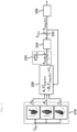
- FIG. 1 is a flowchart of a system for estimating a temperature of a permanent magnet of a rotor of a motor according to a first embodiment of the present invention.
- the system for estimating the temperature of the permanent magnet first determines whether a rotational speed of the rotor included in the motor is greater than or equal to a reference speed.
- ⁇ rpm denotes the rotational speed of the rotor
- ⁇ rpm CO denotes the reference speed.
- Comparison between magnitudes of ⁇ rpm and ⁇ rpm , CO in FIG. 1 is performed by a first determination unit (not illustrated) included in the present embodiment.
- the first determination unit may be implemented as an electronic element capable of calculation or device including the electronic element and may receive rotational speed command value information of the motor from a control device (e.g., an inverter) of the motor.
- a control device e.g., an inverter
- Components to be described below other than the first determination unit may be implemented as the electronic element capable of calculation or device including the electronic element.
- ⁇ rpm is smaller than ⁇ rpm , CO in the first determination unit, in the present invention, it is determined that the temperature of the permanent magnet of the rotor included in the motor is the same as a temperature of a stator of the motor or temperature of a stator coil, and an estimation temperature of the permanent magnet is output by a permanent magnet temperature estimation unit (not illustrated) under a condition of ⁇ rpm ⁇ ⁇ rpm , CO .
- a second determination unit included in the present embodiment determines whether a current flowing in a coil is smaller than a reference current and whether a magnitude of q-axis energy of the motor is smaller than reference energy.
- a current comparison is referred to as a first condition
- a magnitude comparison of the energy is referred to a second condition, in which the first condition can be expressed as I mag ⁇ I mag , CO , and the second condition can be expressed as
- I mag denotes the current flowing in the coil
- I mag,CO denotes the reference current
- E Q denotes the q-axis energy
- E Q CO denotes the reference energy
- a subscript CO in E Q , CO means change over, meaning that it serves as a reference for converting a method of estimating the temperature of the permanent magnet.
- the reference energy may be q-axis reference energy.
- the reference current I mag , CO used as the first condition may be 2 1000 ⁇ V qs R s (V qs denotes a q-axis voltage, and R s denotes a stator resistance), and E Q , CO used in the second condition may be 0.5 joule.
- the present invention does not limit I mag, CO and E Q , CO to the above specific values, and I mag , CO and E Q , CO may be changed as needed.
- an estimated temperature of the permanent magnet is output through a magnetic flux map temperature estimation unit, and when both the first condition and the second condition are not satisfied, in the present embodiment, the temperature of the permanent magnet is estimated and output through an energy map temperature estimation unit.
- FIG. 2 is a block diagram of a magnetic flux map temperature estimation unit of the system for estimating the temperature of the permanent magnet of the rotor of the motor according to the first embodiment of the present invention
- FIG. 3 is a detailed block diagram of the magnetic flux map temperature estimation unit of the system for estimating the temperature of the permanent magnet of the rotor of the motor according to the first embodiment of the present invention.
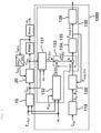
- a magnetic flux map temperature estimation unit 1000 of the system of estimating the temperature of the permanent magnet of the rotor of the motor according to the first embodiment of the present invention includes a 1-1 storage unit (not illustrated), a 1-2 storage unit 110, a 1-1 calculation unit 120, and a 1-2 calculation unit 130.
- the 1-1 storage unit stores data of a d-axis current, q-axis current, and d-axis magnetic flux flowing in the coil of the motor for each temperature acquired through a previously performed test.
- the d-axis magnetic flux at this time while changing the temperature, the d-axis current, and the q-axis current is calculated.
- the calculated d-axis magnetic flux may be calculated using an equation below.
- ⁇ d denotes the d-axis magnetic flux
- V qs denotes the q-axis voltage
- R s denotes the stator resistance
- I qs denotes the q-axis current
- ⁇ r denotes an electric angular speed (rad/s).
- the 1-2 storage unit 110 processes the data using a first-order equation of the d-axis magnetic flux to the temperature.
- the d-axis magnetic flux and temperature may have the linear relationship of the first-order equation, and the 1-2 storage units 110 may acquire data on a coefficient of a first-order term and a constant term in the first-order equation for each d-axis current and q-axis current.
- the coefficient of the first-order term of the first-order equation for each d-axis current and q-axis current can be expressed as A d
- the constant term can be expressed as B d .
- the 1-1 calculation unit 120 When receiving a current command value in controlling the motor, the 1-1 calculation unit 120 outputs a first corrected magnetic flux using the data stored in the 1-2 storage unit 110 and an equation below.
- ⁇ d , Adj A d T mag , Est + B d
- ⁇ d.Adj denotes the first corrected magnetic flux
- a d denotes the coefficient of the first-order term
- B d denotes the constant term
- T mag Est denotes the estimated temperature of the permanent magnet estimated immediately before by the 1-2 calculation unit
- the 1-1 calculation unit 120 calculates and outputs the first corrected magnetic flux ⁇ d.Adj by applying the current command values i ds ⁇ and i qs ⁇ and A d and B d corresponding to the temperature corresponding to T mag , Est output from the 1-2 calculation unit 130 among the data stored in the 1-2 storage unit 110 to the above equation and applying T mag , Est to the above equation.
- T mag , Est used in the above equation denotes the estimated temperature of the permanent magnet estimated immediately before by the 1-2 calculation unit 130. This means that in the present invention, the magnetic flux map temperature estimation unit 1000 repeatedly outputs the estimated temperature of the permanent magnet.
- the 1-2 calculation unit 130 is operated by using a signal output from the 1-1 calculation unit 120. Since the 1-1 calculation unit 120 uses an output signal of the 1-2 calculation unit 130, the 1-1 calculation unit 120 may be controlled in a closed loop.
- the inverter has nonlinearity. Since the nonlinearity of the inverter causes a drop in a voltage and an ON/OFF switching delay of a power semiconductor and changes in magnetic flux and energy caused by a voltage change due to a dead time, the nonlinearity causes errors in estimating the temperature of the permanent magnet. In order to solve this problem, the 1-2 calculation unit 130 removes the errors from the first corrected magnetic flux.
- the 1-2 calculation unit 130 includes a reference magnetic flux generator 131, a first compensation value storage 132, a first compensation applier 133, and a first integral controller 134 and a first temperature estimator 135.
- the reference magnetic flux generator 131 receives the current command value, voltage command value (DC input voltage), and electric angular speed input into the motor and calculates a d-axis reference magnetic flux.
- the current command value can be expressed as i dqs ⁇
- the voltage command value can be expressed as v dqs ⁇
- the electric angular speed can be expressed as ⁇ r
- the d-axis reference magnetic flux can be expressed as ⁇ d , Ref .
- the first compensation value storage 132 stores magnetic flux nonlinearity compensation value data for each DC input voltage, rotational speed, and torque of the motor.
- the DC input voltage can be expressed as v dqs ⁇ or V dc
- the rotational speed can be expressed as ⁇ rpm
- the torque can be expressed as T e ⁇ .
- the first compensation value storage 132 outputs a magnetic flux compensation value corresponding to the input v dqs ⁇ or V dc , ⁇ rpm , and T e ⁇ among the data stored therein.
- the output magnetic flux nonlinearity compensation value is denoted by ⁇ d , NL .
- the first compensation applier 133 subtracts ⁇ d , NL from ⁇ d , Ref and outputs a second corrected magnetic flux ⁇ d , Ref NLC .
- the first compensation applier 133 subtracts ⁇ d.Adj , which is the first corrected magnetic flux output from the 1-1 calculation unit 120, from the second corrected magnetic flux ⁇ d , Ref NLC and outputs ⁇ d , Ref NLC ⁇ ⁇ d , Adj .
- the first integral controller 134 integrally controls ⁇ d , Ref NLC ⁇ ⁇ d , Adj output from the first compensation applier 133.
- the first integral controller sets a bandwidth of a closed-loop system to about a predetermined Hz.
- the bandwidth set by the first integral controller 134 may be set in consideration of a change rate of the temperature of the permanent magnet of the rotor.
- the first temperature estimator 135 adds a temperature measured value of the coil of the motor to the output of the first integral controller 134 and outputs the estimated temperature of the permanent magnet.
- the temperature measured value of the coil of the motor can be expressed as T Sttr
- the estimated temperature of the permanent magnet output from the first temperature estimator 135 can be expressed as T mag , Est .
- T mag , Est output from the first temperature estimator 135 may be output toward the 1-1 calculation unit 120 included in the magnetic flux map temperature estimation unit 1000.
- the 1-2 calculation unit 130 may further include a first output value limiter 136.
- a low-pass filter and SR limiter are devices or circuits for limiting a speed (slew rate (SR)) at which a signal may change over time.
- the first output value limiter 136 serves to prevent distortion or other unwanted effects in the signal by preventing the input T mag , Est from exceeding a specific maximum change rate.
- the low-pass filter or SR limiter can be implemented in a method such as a diode or RC circuit.
- the magnetic flux nonlinearity compensation value data stored in the first compensation value storage 132 will be described.
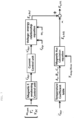
- FIG. 4 is a block diagram of a process of generating magnetic flux nonlinearity compensation value data of the system for estimating the temperature of the permanent magnet of the rotor of the motor according to the first embodiment of the present invention.
- the magnetic flux nonlinearity compensation value data may be obtained through the previously performed test, that is, a test performed offline. More specifically, as illustrated in FIG. 4 , the magnetic flux nonlinearity compensation value data are generated by calculating a first d-axis magnetic flux according to the current command value i dqs ⁇ , voltage command value v dqs ⁇ , and electric angular speed ⁇ r input into the motor, and current command magnetic flux nonlinearity compensation value data input into the motor among the data stored in the 1-2 storage unit 110 may be obtained through the previously tested test, that is, the test performed offline. More specifically, as illustrated in FIG.
- the magnetic flux nonlinearity compensation value data are generated by calculating the first d-axis magnetic flux according to the current command value i dqs ⁇ , voltage command value v dqs ⁇ , and electric angular speed ⁇ r input into the motor, and calculating a second d-axis magnetic flux by inputting a coefficient of the first-order term and constant term corresponding to the current command value i dqs ⁇ input into the motor and T mag , Meas , which is an actually measured temperature of the permanent magnet, into the first-order equation among the data stored in the 1-2 storage unit 110.
- the method of calculating each is the same, and thus the first d-axis magnetic flux is expressed as ⁇ d , Ref and the second d-axis magnetic flux is expressed as ⁇ d.Adj .
- T mag , Meas which is the actually measured temperature of the permanent magnet, may be any one of the temperature information stored in the 1-2 storage unit 110. Then, the magnetic flux nonlinearity compensation value data ⁇ d,NL are generated by subtracting the second d-axis magnetic flux from the first d-axis magnetic flux.
- the input current command value i dqs ⁇ is generated by being converted by a magnetic flux weakening control unit 10 receiving T e ⁇ , which is a torque command value of the motor, the DC voltage V dc , and the rotational speed ⁇ rpm . Therefore, the magnetic flux nonlinearity compensation value data may be obtained for each torque command value, DC voltage, and rotational speed.
- the magnetic flux nonlinearity compensation value data for each voltage value is not acquired, but the nonlinearity compensation value data may be acquired at a minimum DC voltage V DC _ min , a maximum DC voltage V DC_max , and middle DC voltage V DC _ mid .
- FIG. 5 is a block diagram of an energy map temperature estimation unit of the system for estimating the temperature of the permanent magnet of the rotor of the motor according to the first embodiment of the present invention
- FIG. 6 is a detailed block diagram of the energy map temperature estimation unit of the system for estimating the temperature of the permanent magnet of the rotor of the motor according to the first embodiment of the present invention.
- the energy map temperature estimation unit 2000 of the system of estimating the temperature of the permanent magnet of the rotor of the motor according to the first embodiment of the present invention estimates the temperature of the permanent magnet using a q-axis energy map of the motor when any of the first condition and the second condition is not satisfied in the second determination unit.
- the energy map temperature estimation unit 2000 includes a 2-1 storage unit (not illustrated), a 2-2 storage unit 210, a 2-1 calculation unit 220, and a 2-2 calculation unit 230.
- the 2-1 storage unit stores data of a d-axis current, q-axis current, and q-axis energy flowing in the coil of the motor for each temperature acquired through a previously performed test.
- the previously performed test for generating the data stored in the 2-1 storage unit will be described.
- the q-axis energy at this time while changing the temperature, the d-axis current, and the q-axis current is calculated.
- E q denotes the q-axis energy
- V qs denotes the q-axis voltage
- R s denotes the stator resistance
- I qs denotes the q-axis current
- ⁇ r denotes an electric angular speed (rad/s).
- the 2-2 storage unit 210 processes the data using a second-order equation of the q-axis energy to the temperature.
- the q-axis energy and temperature may have the linear relationship of the second-order equation, and the 2-2 storage units 210 may acquire data on a coefficient of a second-order term, a coefficient of a first-order term, and a constant term in the second-order equation for each d-axis current and q-axis current.
- the coefficient of the second-order term of the second-order equation for each d-axis current and q-axis current can be expressed as A e
- the coefficient of the first-order term can be expressed as B e
- the coefficient of the constant term can be expressed as C e .
- the 2-1 calculation unit 220 outputs first corrected energy using the data stored in the 2-2 storage unit 210 and an equation below.
- E q , Adj A e T mag , Est 2 + B e T mag , Est + C e
- E q,Adj denotes the first corrected energy
- a e denotes the coefficient of the second-order term
- B e denotes the coefficient of the first-order term
- C e denotes the constant term
- T mag , Est denotes the estimated temperature of the permanent magnet estimated immediately before by the 2-2 calculation unit
- T mag , Est used in the above equation denotes the estimated temperature of the permanent magnet estimated immediately before by the 2-2 calculation unit 230. This means that in the present invention, the energy map temperature estimation unit 2000 repeatedly outputs the estimated temperature of the permanent magnet.
- the 2-2 calculation unit 230 is operated by using a signal output from the 2-1 calculation unit 220. Since the 2-1 calculation unit 220 uses an output signal of the 2-2 calculation unit 230, the 2-1 calculation unit 220 may be controlled in a closed loop.
- the 2-2 calculation unit 230 removes the errors from the first corrected energy output from the 2-1 calculation unit 220.
- the 2-2 calculation unit 230 includes a reference energy generator 231, a second compensation value storage 232, a second compensation applier 233, and a second integral controller 234 and a second temperature estimator 235.
- the reference energy generator 231 receives the current command value, voltage command value, and electric angular speed input into the motor and calculates q-axis reference energy.
- the current command value can be expressed as i dqs ⁇
- the voltage command value can be expressed as v dqs ⁇
- the speed can be expressed as ⁇ r
- the q-axis reference energy can be expressed as E q , Ref .
- the second compensation value storage 232 stores energy nonlinearity compensation value data for each DC input voltage, rotational speed, and torque of the motor.
- the DC input voltage can be expressed as V dc
- the rotational speed can be expressed as ⁇ rpm
- the torque can be expressed as T e ⁇ .
- the second compensation value storage 232 When receiving V dc , ⁇ rpm , and T e ⁇ , the second compensation value storage 232 outputs energy nonlinearity compensation value corresponding to the input V dc , ⁇ rpm , and T e ⁇ among the data stored therein.
- the energy nonlinearity compensation value is E q , NL .
- the second compensation applier 233 subtracts E q,NL from E q , Ref and outputs a second corrected magnetic flux E q , Ref NLC .
- the second compensation applier 233 subtracts E q .
- Adj which is the first corrected energy output from the energy map temperature estimation unit 2000, from the second corrected energy E q , Ref NLC and outputs E q , Ref NLC ⁇ E q , Adj .
- the second integral controller 234 integrally controls E q , Ref NLC ⁇ E q , Adj output from the second compensation applier 233.
- the second integral controller sets a bandwidth of a closed-loop system to about a predetermined Hz.
- the bandwidth set by the second integral controller 234 may be set in consideration of a change rate of the temperature of the permanent magnet of the rotor.
- the second temperature estimator 235 adds a temperature measured value of the coil of the motor to the output of the second integral controller 234 and outputs the estimated temperature of the permanent magnet.
- the temperature measured value of the coil of the motor can be expressed as T Sttr
- the estimated temperature of the permanent magnet output from the second temperature estimator 235 can be expressed as T mag , Est .
- T mag , Est output from the second temperature estimator 235 may be output toward the 2-1 calculation unit 220 included in the energy map temperature estimation unit 2000.
- the 2-2 calculation unit 230 may further include a second output value limiter 236.
- the second output value limiter 236 can be implemented as a low-pass filter (LPF) or SR limiter.
- LPF low-pass filter
- SR limiter are devices or circuits for limiting a speed (slew rate (SR)) at which a signal may change over time.
- the second output value limiter 236 serves to prevent distortion or other unwanted effects in the signal by preventing the input T mag , Est from exceeding a specific maximum change rate.
- the low-pass filter or SR limiter can be implemented in a method such as a diode or RC circuit.
- the energy nonlinearity compensation value data stored in the second compensation value storage 232 will be described.
- FIG. 7 is a block diagram of a process of generating energy nonlinearity compensation value data of the system for estimating the temperature of the permanent magnet of the rotor of the motor according to the first embodiment of the present invention.
- the energy nonlinearity compensation value data may be obtained through the previously tested test, that is, a test performed offline. More specifically, as illustrated in FIG. 7 , the energy nonlinearity compensation value data is generated by calculating first d-axis energy according to the current command value i dqs ⁇ , voltage command value v dqs ⁇ , and electric angular speed ⁇ r input into the motor, and calculating second q-axis energy by inputting a coefficient of the second-order term, coefficient of the first-order term, and constant term corresponding to the current command value i dqs ⁇ input into the motor and T mag , Meas , which is an actually measured temperature of the permanent magnet, into the second-order equation.
- the method of calculating each is the same, and thus the first q-axis energy is expressed as E q , Ref and the second d-axis magnetic flux is expressed as E q , Adj .
- T mag , Meas which is the actually measured temperature of the permanent magnet, may be any one of the temperature information stored in the 2-2 storage unit 210.
- the energy nonlinearity compensation value data E q , NL are generated by subtracting the second q-axis energy from the first q-axis energy. As illustrated in FIG.
- the input current command value i dqs ⁇ is generated by being converted by a magnetic flux weakening control unit 10 receiving T e ⁇ , which is a torque command value of the motor, the DC voltage V dc , and the rotational speed ⁇ rpm . Therefore, the energy nonlinearity compensation value data may be obtained for each torque command value, DC voltage, and rotational speed.
- the magnetic flux nonlinearity compensation value data for each voltage value is not acquired, but the nonlinearity compensation value data may be acquired at a minimum DC voltage V DC_min , a maximum DC voltage V DC _ max , and middle DC voltage V DC _ mid .
- the system for estimating the temperature of the permanent magnet of the rotor of the motor according to the present invention may be continuously performed during operation. In other words, the system does not end with estimating the temperature of the permanent magnet of the rotor once, but determines a condition in each of the first determination unit and the second determination unit and then estimates the temperature of the permanent magnet of the rotor in a different manner as the condition changes.
- the present invention by estimating the temperature of the permanent magnet using the temperature of the stator coil, estimating the temperature of the permanent magnet using the magnetic flux map, or estimating the temperature of the permanent magnet using the energy map according to the conditions, it is possible to increase the temperature estimation accuracy of the permanent magnet.
- the system such as the system of the present invention is applied, it is possible to prevent the degradation in the performance of the motor by controlling the temperature of the permanent magnet to 180 to 200 °C or lower to prevent the permanent magnet from entering a high temperature at which irreversible demagnetization occurs.
- this system when this system is applied to electric vehicles, it is possible to increase driving distances of the electric vehicles by reducing a loss of a cooling system of the vehicle, and improve the efficiency of the entirety of the vehicle by reducing coolant or a flow rate of the coolant.
- the first integral controller 134 and the second integral controller 234 are positioned at a frontmost end in a signal processing direction.
- first integral controller 134 and the second integral controller 234 are implemented as the same device and are referred to as the first integral controller 134
- a change-over switch is provided between the first integral controller 134 and the first compensation applier 133 and between the first integral controller 134 and the second compensation applier 233 to connect the first integral controller 134 to the first compensation applier 133 when the magnetic flux map temperature estimating method is used or connect the first integral controller 134 to the second compensation applier 233 when the energy map temperature estimating method is used.
- the system for estimating the temperature of the permanent magnet of the rotor of the motor according to the present invention, by monitoring the temperature of the permanent magnet in real time, it is possible to prevent degradation the performance of the permanent magnet due to the high temperature and improve the output torque control precision and efficiency of the motor.
Landscapes
- Engineering & Computer Science (AREA)
- Power Engineering (AREA)
- Control Of Ac Motors In General (AREA)
Abstract
Description
- The present invention relates to a system for estimating a temperature of a permanent magnet of a rotor of a motor, and more specifically, to a system for estimating a temperature of a permanent magnet of a rotor for a motor, which may monitor the temperature of the permanent magnet attached to the rotor of the motor in real time.
- In a motor, since the magnetic characteristics of a permanent magnet included in the motor change depending on a temperature, it is necessary to estimate a temperature of the permanent magnet. In order to accurately measure a temperature of a permanent magnet included in a rotor of the motor, a separate sensor and communication module are required, resulting in an increase in prices of the motor and an inverter, and thus a problem that the price competitiveness of a product is degraded occurs.
- There are mainly three methods proposed to solve this problem: a method of assuming that a temperature of a stator coil and a temperature of a permanent magnet of a rotor are the same (hereinafter referred to as "first method"), a method of estimating a temperature of a permanent of a rotor by generating a three-dimensional magnetic flux map for a speed, torque, and temperature of the rotor of a motor (hereinafter referred to as "second method"), and a method of estimating a temperature of a permanent magnet using a thermal resistance of a motor and the characteristics of a cooling system (hereinafter referred to as "third method").
- The first method among the above methods has a problem of low torque control precision because it is not based on the temperature of the permanent magnet of the rotor of the motor.
- The second method has a problem that a temperature estimation error increases according to a change in battery voltage (or a direct-current high voltage) because it does not consider a magnetic flux change according to a voltage change in a high-voltage battery. In order to consider a change in battery voltage, a four-dimensional magnetic flux map should be generated or three or more sets of three-dimensional magnetic flux maps should be generated, which has a problem that many CPU memories are occupied and it takes much time to develop the magnetic flux map.
- The third method may have the performance of the cooling system that changes according to a vehicle driving environment. When the performance of the cooling system changes, thermal resistances of a rotor and a stator of the motor varies depending on a flow rate of a cooling medium. In order to solve this problem, it is necessary to identify the heating amount of the motor and model copper and iron losses of the stator according to a torque and a speed, and there is a problem that a development time is excessively required.
- This Summary is provided to introduce a selection of concepts in a simplified form that are further described below in the Detailed Description. This Summary is not intended to identify key features or essential features of the claimed subject matter, nor is it intended to be used as an aid in determining the scope of the claimed subject matter.
- In a general aspect, here is provided a system for estimating a temperature of a permanent magnet of a rotor of a motor including a first determination unit configured to determine whether a rotational speed of the rotor is greater than or equal to a reference speed, a second determination unit configured to determine a first condition, the first condition being whether a current flowing in a coil included in the motor is less than a reference current, and a second condition, the second condition being whether a magnitude of q-axis energy of the motor is less than a reference energy magnitude, when the rotational speed is greater than or equal to the reference speed, a magnetic flux map temperature estimation unit configured to estimate the temperature of the permanent magnet included in the rotor using a d-axis magnetic flux map of the motor responsive to one or more of the first condition and the second condition is satisfied in the second determination unit, and an energy map temperature estimation unit configured to estimate the temperature of the permanent magnet using a q-axis energy map of the motor responsive to one or more of the first condition and the second condition not being satisfied in the second determination unit.
- The magnetic flux map temperature estimation unit may include a first storage unit configured to store data on a d-axis current, q-axis current, and d-axis magnetic flux flowing in the coil of the motor for each temperature acquired through a previously performed test, a second storage unit configured to process the data stored in the first storage unit using a first-order equation of the d-axis magnetic flux to the temperature for each d-axis current and q-axis current, and to calculate data on a coefficient of a first-order term and a constant term for each d-axis current and q-axis current of the first-order equation, a first calculation unit configured to calculate a first corrected magnetic flux using the data stored in the second storage unit and an equation below, and a second calculation unit configured to remove errors from the first corrected magnetic flux and to calculate the estimated temperature of the permanent magnet, and when receiving a current command value of the motor, the first calculation unit inputs a coefficient of the first-order term and a constant term corresponding to the current command value and an estimated temperature of the permanent magnet estimated before by the second calculation unit among the data stored in the second storage unit into the equation,

in the equation, Ad.Adj denotes the first corrected magnetic flux, Ad denotes the coefficient of the first-order term, Bd denotes the constant term, and T mag,Est denotes the estimated temperature of the permanent magnet estimated before by the second calculation unit. - The second calculation unit may include a reference magnetic flux generator configured to calculate a d-axis reference magnetic flux according to the current command value, a voltage command value, and an electric angular speed input into the motor, a first compensation value storage unit configured to store magnetic flux nonlinearity compensation value data for each DC input voltage, rotational speed, and torque of the motor and calculate a magnetic flux nonlinearity compensation value according to the DC input voltage, the rotational speed, and the torque of the motor, a first compensation applier configured to generate a second corrected magnetic flux by subtracting the magnetic flux nonlinearity compensation value from the d-axis reference magnetic flux and the first corrected magnetic flux, a first integral controller configured to receive and integrally control a value received from the first compensation applier, and a first temperature estimator configured to add a temperature measured value of the coil of the motor to an output of the first integral controller and to calculate the estimated temperature of the permanent magnet.
- The second calculation unit further may include a first output value limiter configured to filter the estimated temperature of the permanent magnet from the first temperature estimator or calculate the estimated temperature of the permanent magnet by limiting a change rate of the estimated temperature of the permanent magnet.
- A calculation of the magnetic flux nonlinearity compensation value data may include calculating a first d-axis magnetic flux according to the current command value, the voltage command value, and the electric angular speed input into the motor through a previously performed test, calculating a second d-axis magnetic flux by inputting an actually measured temperature of the permanent magnet into the first-order equation and inputting a coefficient of the first-order term and the constant term according to the d-axis current and q-axis current according to the current command value input into the motor and the actually measured temperature of the permanent magnet among the data stored in the second storage unit, and subtracting the second d-axis magnetic flux from the first d-axis magnetic flux.
- The energy map temperature estimation unit may include a third storage unit in which data on a d-axis current, q-axis current, and q-axis energy flowing in the coil of the motor for each temperature from a previously performed test is stored, a fourth storage unit configured to process the data stored in the third storage unit using a second-order equation of the q-axis energy to the temperature for each d-axis current and q-axis current, and to generate and store data on a coefficient of a second-order term, a coefficient of a first-order term, and a constant term for each d-axis current and q-axis current of the second-order equation, a third calculation unit configured to calculate a first corrected energy value using the data stored in the fourth storage unit and an equation below, and a fourth calculation unit configured to remove errors from the first corrected energy value and then calculate the estimated temperature of the permanent magnet, and when receiving a current command value of the motor, the third calculation unit inputs a coefficient of the second-order term, a coefficient of the first-order term, and a constant term corresponding to the current command value and an estimated temperature of the permanent magnet estimated before by the fourth calculation unit among the data stored in the fourth storage unit into the equation,

and in the equation, Eq.Adj denotes the first corrected energy, Ae denotes the coefficient of the second-order term, Be denotes the coefficient of the first-order term, Ce denotes the constant term, and T mag,Est denotes the estimated temperature of the permanent magnet estimated before by the fourth calculation unit. - The fourth calculation unit may include a reference energy generator configured to calculate a q-axis reference energy according to the current command value, a voltage command value, and a speed input into the motor, a first compensation value storage configured to store energy nonlinearity compensation value data for each DC input voltage, rotational speed, and torque of the motor and calculate an energy nonlinearity compensation value according to the DC input voltage, the rotational speed, and the torque of the motor, a second compensation applier configured to generate second corrected energy by subtracting the energy nonlinearity compensation value from the q-axis reference energy and output the first corrected energy from the second corrected energy, a second integral controller configured to receive and integrally control an output value of the second compensation applier, and a second temperature estimator configured to add a temperature measured value of the coil of the motor to an output of the second integral controller and calculate the estimated temperature of the permanent magnet.
- The fourth calculation unit further may include a second output value limiter configured to receive and filter the estimated temperature of the permanent magnet output from the second temperature estimator or to calculate the estimated temperature of the permanent magnet by limiting a change rate of the estimated temperature of the permanent magnet.
- A calculation of the energy nonlinearity compensation value data may include calculating first q-axis energy according to the current command value, the voltage command value, and the electric angular speed input into the motor through a previously performed test, calculating second q-axis energy by inputting an actually measured temperature of the permanent magnet into the second-order equation and inputting a coefficient of the second-order term, a coefficient of the first-order term, and the constant term according to the d-axis current and q-axis current according to the current command value input into the motor and the actually measured temperature of the permanent magnet among the data stored in the fourth storage unit, and subtracting the second q-axis energy from the first q-axis energy.
- The system may include a basic permanent magnet temperature estimator configured to calculate a temperature measured value of a stator coil of the motor as the estimated temperature of the permanent magnet when the rotational speed of the rotor included in the motor is lower than the reference speed.
- In a general aspect, here is provided a temperature estimation apparatus including one or more processors configured to execute instructions and a memory storing the instructions, wherein execution of the instructions configures the one or more processors to determine whether a rotational speed of a rotor of a motor is greater than or equal to a reference speed, determine a first condition, the first condition being whether a current flowing in a coil of the motor is less than a reference current, and a second condition, the second condition being whether a magnitude of q-axis energy of the motor is less than a reference energy magnitude, when the rotational speed is greater than or equal to the reference speed, estimate a magnetic flux map of the temperature of a permanent magnet of the rotor using a d-axis magnetic flux map of the motor responsive to one or more of the first condition and the second condition being satisfied, and estimate an energy map of the temperature of the permanent magnet using a q-axis energy map of the motor responsive to one or more of the first condition and the second condition not being satisfied.
- The estimation of the magnetic flux map may include storing first data on a d-axis current, q-axis current, and d-axis magnetic flux flowing in the coil of the motor for each temperature acquired through a previously performed test, processing the first data using a first-order equation of the d-axis magnetic flux to the temperature for each d-axis current and q-axis current, and to calculate second data on a coefficient of a first-order term and a constant term for each d-axis current and q-axis current of the first-order equation, calculating a first corrected magnetic flux using the second data and an equation below, and removing errors from the first corrected magnetic flux and to calculate the estimated temperature of the permanent magnet, and, when receiving a current command value of the motor, inputting a coefficient of the first-order term and a constant term corresponding to the current command value and an estimated temperature of the permanent magnet estimated from among the second data into the equation,

in the equation, Ad.Adj denotes the first corrected magnetic flux, denotes the coefficient of the first-order term, Bd denotes the constant term, and T mag,Est denotes the estimated temperature of the permanent magnet. - The processor may be further configured to calculate a d-axis reference magnetic flux according to the current command value, a voltage command value, and an electric angular speed input into the motor, store magnetic flux nonlinearity compensation value data for each DC input voltage, rotational speed, and torque of the motor and calculate a magnetic flux nonlinearity compensation value according to the DC input voltage, the rotational speed, and the torque of the motor, generate, via a first compensation applier, a second corrected magnetic flux by subtracting the magnetic flux nonlinearity compensation value from the d-axis reference magnetic flux and the first corrected magnetic flux, receive and integrally control a first value received from the first compensation applier, and add a temperature measured value of the coil of the motor to the first value and to calculate the estimated temperature of the permanent magnet.
- The processor may be further configured to filter the estimated temperature of the permanent magnet from or calculate the estimated temperature of the permanent magnet by limiting a change rate of the estimated temperature of the permanent magnet.
- A calculation of the magnetic flux nonlinearity compensation value data may include calculating a first d-axis magnetic flux according to the current command value, the voltage command value, and the electric angular speed input into the motor through a previously performed test, calculating a second d-axis magnetic flux by inputting an actually measured temperature of the permanent magnet into the first-order equation and inputting a coefficient of the first-order term and the constant term according to the d-axis current and q-axis current according to the current command value input into the motor and the actually measured temperature of the permanent magnet among the second data, and subtracting the second d-axis magnetic flux from the first d-axis magnetic flux.
- The estimation of the energy map may include storing third data on a d-axis current, q-axis current, and q-axis energy flowing in the coil of the motor for each temperature from a previously performed test is stored, processing the third data using a second-order equation of the q-axis energy to the temperature for each d-axis current and q-axis current, and to generate and store data on a coefficient of a second-order term, a coefficient of a first-order term, and a constant term for each d-axis current and q-axis current of the second-order equation, calculating a first corrected energy value using the fourth data and an equation below, and removing errors from the first corrected energy value and then calculate the estimated temperature of the permanent magnet, and, when receiving a current command value of the motor, inputting a coefficient of the second-order term, a coefficient of the first-order term, and a constant term corresponding to the current command value and an estimated temperature of the permanent magnet estimated before from among the fourth data into the equation,

and in the equation, Eq.Adj denotes the first corrected energy, Ae denotes the coefficient of the second-order term, Be denotes the coefficient of the first-order term, Ce denotes the constant term, and T mag,Est denotes the estimated temperature of the permanent magnet. - The processor may be further configured to calculate a q-axis reference energy according to the current command value, a voltage command value, and a speed input into the motor,
store energy nonlinearity compensation value data for each DC input voltage, rotational speed, and torque of the motor and calculate an energy nonlinearity compensation value according to the DC input voltage, the rotational speed, and the torque of the motor, generate, via a second compensation applier, second corrected energy by subtracting the energy nonlinearity compensation value from the q-axis reference energy and output the first corrected energy from the second corrected energy, receive and integrally control a second output value of the second compensation applier, and add a temperature measured value of the coil of the motor to the second output value and calculate the estimated temperature of the permanent magnet. - The removing the errors from the first corrected energy may include filtering the estimated temperature of the permanent magnet or to calculate the estimated temperature of the permanent magnet by limiting a change rate of the estimated temperature of the permanent magnet.
- A calculation of the energy nonlinearity compensation value data may include calculating first q-axis energy according to the current command value, the voltage command value, and the electric angular speed input into the motor through a previously performed test, calculating second q-axis energy by inputting an actually measured temperature of the permanent magnet into the second-order equation and inputting a coefficient of the second-order term, a coefficient of the first-order term, and the constant term according to the d-axis current and q-axis current according to the current command value input into the motor and the actually measured temperature of the permanent magnet among the fourth data, and subtracting the second q-axis energy from the first q-axis energy.
- The processor may be further configured to calculate a temperature measured value of a stator coil of the motor as the estimated temperature of the permanent magnet when the rotational speed of the rotor included in the motor is lower than the reference speed.
-
-
FIG. 1 is a flowchart of a system for estimating a temperature of a permanent magnet of a rotor of a motor according to a first embodiment of the present invention. -
FIG. 2 is a block diagram of a magnetic flux map temperature estimation unit of the system for estimating the temperature of the permanent magnet of the rotor of the motor according to the first embodiment of the present invention. -
FIG. 3 is a detailed block diagram of the magnetic flux map temperature estimation unit of the system for estimating the temperature of the permanent magnet of the rotor of the motor according to the first embodiment of the present invention. -
FIG. 4 is a block diagram of a process of generating magnetic flux nonlinearity compensation value data of the system for estimating the temperature of the permanent magnet of the rotor of the motor according to the first embodiment of the present invention. -
FIG. 5 is a block diagram of an energy map temperature estimation unit of the system for estimating the temperature of the permanent magnet of the rotor of the motor according to the first embodiment of the present invention. -
FIG. 6 is a detailed block diagram of the energy map temperature estimation unit of the system for estimating the temperature of the permanent magnet of the rotor of the motor according to the first embodiment of the present invention. -
FIG. 7 is a block diagram of a process of generating energy nonlinearity compensation value data of the system for estimating the temperature of the permanent magnet of the rotor of the motor according to the first embodiment of the present invention. - Throughout the drawings and the detailed description, unless otherwise described or provided, the same, or like, drawing reference numerals may be understood to refer to the same, or like, elements, features, and structures. The drawings may not be to scale, and the relative size, proportions, and depiction of elements in the drawings may be exaggerated for clarity, illustration, and convenience.
- The following detailed description is provided to assist the reader in gaining a comprehensive understanding of the methods, apparatuses, and/or systems described herein. However, various changes, modifications, and equivalents of the methods, apparatuses, and/or systems described herein will be apparent after an understanding of the disclosure of this application. For example, the sequences of operations described herein are merely examples, and are not limited to those set forth herein, but may be changed as will be apparent after an understanding of the disclosure of this application, with the exception of operations necessarily occurring in a certain order.
- The features described herein may be embodied in different forms and are not to be construed as being limited to the examples described herein. Rather, the examples described herein have been provided merely to illustrate some of the many possible ways of implementing the methods, apparatuses, and/or systems described herein that will be apparent after an understanding of the disclosure of this application.
- Advantages and features of the present disclosure and methods of achieving the advantages and features will be clear with reference to embodiments described in detail below together with the accompanying drawings. However, the present disclosure is not limited to the embodiments disclosed herein but will be implemented in various forms. The embodiments of the present disclosure are provided so that the present disclosure is completely disclosed, and a person with ordinary skill in the art can fully understand the scope of the present disclosure. The present disclosure will be defined only by the scope of the appended claims. Meanwhile, the terms used in the present specification are for explaining the embodiments, not for limiting the present disclosure.
- Terms, such as first, second, A, B, (a), (b) or the like, may be used herein to describe components. Each of these terminologies is not used to define an essence, order or sequence of a corresponding component but used merely to distinguish the corresponding component from other component(s). For example, a first component may be referred to as a second component, and similarly the second component may also be referred to as the first component.
- Throughout the specification, when a component is described as being "connected to," or "coupled to" another component, it may be directly "connected to," or "coupled to" the other component, or there may be one or more other components intervening therebetween. In contrast, when an element is described as being "directly connected to," or "directly coupled to" another element, there can be no other elements intervening therebetween.
- In a description of the embodiment, in a case in which any one element is described as being formed on or under another element, such a description includes both a case in which the two elements are formed in direct contact with each other and a case in which the two elements are in indirect contact with each other with one or more other elements interposed between the two elements. In addition, when one element is described as being formed on or under another element, such a description may include a case in which the one element is formed at an upper side or a lower side with respect to another element.
- The singular forms "a", "an", and "the" are intended to include the plural forms as well, unless the context clearly indicates otherwise. It will be further understood that the terms "comprises/comprising" and/or "includes/including" when used herein, specify the presence of stated features, integers, steps, operations, elements, and/or components, but do not preclude the presence or addition of one or more other features, integers, steps, operations, elements, components and/or groups thereof.
-
FIG. 1 is a flowchart of a system for estimating a temperature of a permanent magnet of a rotor of a motor according to a first embodiment of the present invention. - As illustrated in
FIG. 1 , the system for estimating the temperature of the permanent magnet according to the first embodiment of the present invention first determines whether a rotational speed of the rotor included in the motor is greater than or equal to a reference speed. As illustrated inFIG. 1 , ωrpm denotes the rotational speed of the rotor, and ω rpm,CO denotes the reference speed. Comparison between magnitudes of ωrpm and ω rpm,CO inFIG. 1 is performed by a first determination unit (not illustrated) included in the present embodiment. To this end, the first determination unit may be implemented as an electronic element capable of calculation or device including the electronic element and may receive rotational speed command value information of the motor from a control device (e.g., an inverter) of the motor. Components to be described below other than the first determination unit may be implemented as the electronic element capable of calculation or device including the electronic element. - When ωrpm is smaller than ω rpm,CO in the first determination unit, in the present invention, it is determined that the temperature of the permanent magnet of the rotor included in the motor is the same as a temperature of a stator of the motor or temperature of a stator coil, and an estimation temperature of the permanent magnet is output by a permanent magnet temperature estimation unit (not illustrated) under a condition of ωrpm < ω rpm,CO .
- When a condition of ωrpm ≥ ω rpm,CO is satisfied in the first determination unit, a second determination unit (not illustrated) included in the present embodiment determines whether a current flowing in a coil is smaller than a reference current and whether a magnitude of q-axis energy of the motor is smaller than reference energy. A current comparison is referred to as a first condition, and a magnitude comparison of the energy is referred to a second condition, in which the first condition can be expressed as Imag < I mag,CO , and the second condition can be expressed as |EQ | < E Q, CO. In this case, Imag denotes the current flowing in the coil, Imag,CO denotes the reference current, EQ denotes the q-axis energy, and E Q,CO denotes the reference energy. A subscript CO in E Q,CO means change over, meaning that it serves as a reference for converting a method of estimating the temperature of the permanent magnet. The reference energy may be q-axis reference energy. In the present embodiment, the reference current I mag,CO used as the first condition may be

- In the present embodiment, when at least one of the first condition and the second condition is satisfied in the second determination unit, an estimated temperature of the permanent magnet is output through a magnetic flux map temperature estimation unit, and when both the first condition and the second condition are not satisfied, in the present embodiment, the temperature of the permanent magnet is estimated and output through an energy map temperature estimation unit. This is to increase the accuracy of the estimated temperature of the permanent magnet, and since there is a disadvantage in that a method using a magnetic flux map has a large influence of a resistance change when a current increases, and there is a disadvantage in that a method using an energy map may not be used for temperature estimation when a current is zero, it is possible to increase accuracy by selecting any one of the two methods according to situations and estimating the temperature of the permanent magnet.
- Hereinafter, a detailed method of estimating the temperature of the permanent magnet by the magnetic flux map temperature estimation unit among the magnetic flux map temperature estimation unit and the energy map temperature estimation unit will be first described.
-
FIG. 2 is a block diagram of a magnetic flux map temperature estimation unit of the system for estimating the temperature of the permanent magnet of the rotor of the motor according to the first embodiment of the present invention, andFIG. 3 is a detailed block diagram of the magnetic flux map temperature estimation unit of the system for estimating the temperature of the permanent magnet of the rotor of the motor according to the first embodiment of the present invention. - As illustrated in
FIGS. 2 and3 , a magnetic flux maptemperature estimation unit 1000 of the system of estimating the temperature of the permanent magnet of the rotor of the motor according to the first embodiment of the present invention includes a 1-1 storage unit (not illustrated), a 1-2storage unit 110, a 1-1calculation unit 120, and a 1-2calculation unit 130. - The 1-1 storage unit stores data of a d-axis current, q-axis current, and d-axis magnetic flux flowing in the coil of the motor for each temperature acquired through a previously performed test.
- The previously performed test for generating the data stored in the 1-1 storage unit will be described. First, the d-axis magnetic flux at this time while changing the temperature, the d-axis current, and the q-axis current is calculated. The calculated d-axis magnetic flux may be calculated using an equation below.

- In the above equation, λd denotes the d-axis magnetic flux, Vqs denotes the q-axis voltage, Rs denotes the stator resistance, Iqs denotes the q-axis current, and ωr denotes an electric angular speed (rad/s). When the test is performed using the above equation, magnetic flux data sets according to the d-axis current, q-axis current, and temperature are acquired.
- When the d-axis current and q-axis current are fixed by processing the data stored in the 1-1 storage unit, the 1-2
storage unit 110 processes the data using a first-order equation of the d-axis magnetic flux to the temperature. When the d-axis current and q-axis current are fixed, the d-axis magnetic flux and temperature may have the linear relationship of the first-order equation, and the 1-2storage units 110 may acquire data on a coefficient of a first-order term and a constant term in the first-order equation for each d-axis current and q-axis current. The coefficient of the first-order term of the first-order equation for each d-axis current and q-axis current can be expressed as Ad , and the constant term can be expressed as Bd . - When receiving a current command value in controlling the motor, the 1-1
calculation unit 120 outputs a first corrected magnetic flux using the data stored in the 1-2storage unit 110 and an equation below.

- (In the above equation, λd.Adj denotes the first corrected magnetic flux, Ad denotes the coefficient of the first-order term, Bd denotes the constant term, and T mag,Est denotes the estimated temperature of the permanent magnet estimated immediately before by the 1-2 calculation unit).
- More specifically, when

storage unit 110, the 1-1calculation unit 120 calculates and outputs the first corrected magnetic flux λd.Adj by applying the current command values

calculation unit 130 among the data stored in the 1-2storage unit 110 to the above equation and applying T mag,Est to the above equation. - T mag,Est used in the above equation denotes the estimated temperature of the permanent magnet estimated immediately before by the 1-2
calculation unit 130. This means that in the present invention, the magnetic flux maptemperature estimation unit 1000 repeatedly outputs the estimated temperature of the permanent magnet. - The 1-2
calculation unit 130 is operated by using a signal output from the 1-1calculation unit 120. Since the 1-1calculation unit 120 uses an output signal of the 1-2calculation unit 130, the 1-1calculation unit 120 may be controlled in a closed loop. - The inverter has nonlinearity. Since the nonlinearity of the inverter causes a drop in a voltage and an ON/OFF switching delay of a power semiconductor and changes in magnetic flux and energy caused by a voltage change due to a dead time, the nonlinearity causes errors in estimating the temperature of the permanent magnet. In order to solve this problem, the 1-2
calculation unit 130 removes the errors from the first corrected magnetic flux. - For the above operation, the 1-2
calculation unit 130 includes a referencemagnetic flux generator 131, a firstcompensation value storage 132, afirst compensation applier 133, and a firstintegral controller 134 and afirst temperature estimator 135. - The reference
magnetic flux generator 131 receives the current command value, voltage command value (DC input voltage), and electric angular speed input into the motor and calculates a d-axis reference magnetic flux. In this case, the current command value can be expressed as

- The first
compensation value storage 132 stores magnetic flux nonlinearity compensation value data for each DC input voltage, rotational speed, and torque of the motor. The DC input voltage can be expressed as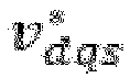

magnetic flux generator 131 receives

compensation value storage 132 outputs a magnetic flux compensation value corresponding to the input

- The
first compensation applier 133 subtracts λ d,NL from λ d,Ref and outputs a second corrected magnetic flux
first compensation applier 133 subtracts λd.Adj , which is the first corrected magnetic flux output from the 1-1calculation unit 120, from the second corrected magnetic flux

- The first
integral controller 134 integrally controls
first compensation applier 133. The first integral controller sets a bandwidth of a closed-loop system to about a predetermined Hz. The bandwidth set by the firstintegral controller 134 may be set in consideration of a change rate of the temperature of the permanent magnet of the rotor. - The
first temperature estimator 135 adds a temperature measured value of the coil of the motor to the output of the firstintegral controller 134 and outputs the estimated temperature of the permanent magnet. The temperature measured value of the coil of the motor can be expressed as TSttr , and the estimated temperature of the permanent magnet output from thefirst temperature estimator 135 can be expressed as T mag,Est . T mag,Est output from thefirst temperature estimator 135 may be output toward the 1-1calculation unit 120 included in the magnetic flux maptemperature estimation unit 1000. - As illustrated in
FIGS. 2 and3 , the 1-2calculation unit 130 may further include a firstoutput value limiter 136. - In the field of signal engineering, a low-pass filter and SR limiter are devices or circuits for limiting a speed (slew rate (SR)) at which a signal may change over time. In other words, the first
output value limiter 136 serves to prevent distortion or other unwanted effects in the signal by preventing the input T mag,Est from exceeding a specific maximum change rate. The low-pass filter or SR limiter can be implemented in a method such as a diode or RC circuit. - The magnetic flux nonlinearity compensation value data stored in the first
compensation value storage 132 will be described. -
FIG. 4 is a block diagram of a process of generating magnetic flux nonlinearity compensation value data of the system for estimating the temperature of the permanent magnet of the rotor of the motor according to the first embodiment of the present invention. - The magnetic flux nonlinearity compensation value data may be obtained through the previously performed test, that is, a test performed offline. More specifically, as illustrated in
FIG. 4 , the magnetic flux nonlinearity compensation value data are generated by calculating a first d-axis magnetic flux according to the current command value

storage unit 110 may be obtained through the previously tested test, that is, the test performed offline. More specifically, as illustrated inFIG. 4 , the magnetic flux nonlinearity compensation value data are generated by calculating the first d-axis magnetic flux according to the current command value


storage unit 110. Although the first d-axis magnetic flux and second d-axis magnetic flux calculated when the magnetic flux nonlinearity compensation value data is generated differ from the above-described d-axis reference magnetic flux and first corrected magnetic flux, the method of calculating each is the same, and thus the first d-axis magnetic flux is expressed as λ d,Ref and the second d-axis magnetic flux is expressed as λd.Adj . T mag,Meas , which is the actually measured temperature of the permanent magnet, may be any one of the temperature information stored in the 1-2storage unit 110. Then, the magnetic flux nonlinearity compensation value data λd,NL are generated by subtracting the second d-axis magnetic flux from the first d-axis magnetic flux. As illustrated inFIG. 4 , in order to calculate the first d-axis magnetic flux, the input current command value
weakening control unit 10 receiving
- Hereinafter, an operation of an energy map
temperature estimation unit 2000 will be described. -
FIG. 5 is a block diagram of an energy map temperature estimation unit of the system for estimating the temperature of the permanent magnet of the rotor of the motor according to the first embodiment of the present invention, andFIG. 6 is a detailed block diagram of the energy map temperature estimation unit of the system for estimating the temperature of the permanent magnet of the rotor of the motor according to the first embodiment of the present invention. - As illustrated in
FIGS. 5 and6 , the energy maptemperature estimation unit 2000 of the system of estimating the temperature of the permanent magnet of the rotor of the motor according to the first embodiment of the present invention estimates the temperature of the permanent magnet using a q-axis energy map of the motor when any of the first condition and the second condition is not satisfied in the second determination unit. As illustrated inFIGS. 5 and6 , the energy maptemperature estimation unit 2000 includes a 2-1 storage unit (not illustrated), a 2-2storage unit 210, a 2-1calculation unit 220, and a 2-2calculation unit 230. - The 2-1 storage unit stores data of a d-axis current, q-axis current, and q-axis energy flowing in the coil of the motor for each temperature acquired through a previously performed test.
- The previously performed test for generating the data stored in the 2-1 storage unit will be described. First, the q-axis energy at this time while changing the temperature, the d-axis current, and the q-axis current is calculated. The q-axis energy may be calculated using an equation below.
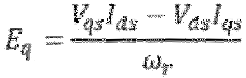
- In the above equation, Eq denotes the q-axis energy, Vqs denotes the q-axis voltage, Rs denotes the stator resistance, Iqs denotes the q-axis current, and ωr denotes an electric angular speed (rad/s). When the test is performed using the above equation, data sets of the q-axis energy according to the d-axis current, q-axis current, and temperature are acquired.
- When the d-axis current and q-axis current are fixed by processing the data stored in the 2-1 storage unit, the 2-2
storage unit 210 processes the data using a second-order equation of the q-axis energy to the temperature. When the d-axis current and q-axis current are fixed, the q-axis energy and temperature may have the linear relationship of the second-order equation, and the 2-2storage units 210 may acquire data on a coefficient of a second-order term, a coefficient of a first-order term, and a constant term in the second-order equation for each d-axis current and q-axis current. The coefficient of the second-order term of the second-order equation for each d-axis current and q-axis current can be expressed as Ae , the coefficient of the first-order term can be expressed as Be , and the coefficient of the constant term can be expressed as Ce . - The 2-1
calculation unit 220 outputs first corrected energy using the data stored in the 2-2storage unit 210 and an equation below.
- (In the above equation, Eq,Adj denotes the first corrected energy, Ae denotes the coefficient of the second-order term, Be denotes the coefficient of the first-order term, Ce denotes the constant term, and T mag,Est denotes the estimated temperature of the permanent magnet estimated immediately before by the 2-2 calculation unit).
- T mag,Est used in the above equation denotes the estimated temperature of the permanent magnet estimated immediately before by the 2-2
calculation unit 230. This means that in the present invention, the energy maptemperature estimation unit 2000 repeatedly outputs the estimated temperature of the permanent magnet. - The 2-2
calculation unit 230 is operated by using a signal output from the 2-1calculation unit 220. Since the 2-1calculation unit 220 uses an output signal of the 2-2calculation unit 230, the 2-1calculation unit 220 may be controlled in a closed loop. - Like the above description of the magnetic flux map
temperature estimation unit 1000, errors are included in the first corrected energy output from the 2-1calculation unit 220. The 2-2calculation unit 230 removes the errors from the first corrected energy output from the 2-1calculation unit 220. - For the above operation, the 2-2
calculation unit 230 includes areference energy generator 231, a secondcompensation value storage 232, asecond compensation applier 233, and a secondintegral controller 234 and asecond temperature estimator 235. - The
reference energy generator 231 receives the current command value, voltage command value, and electric angular speed input into the motor and calculates q-axis reference energy. In this case, the current command value can be expressed as

- The second
compensation value storage 232 stores energy nonlinearity compensation value data for each DC input voltage, rotational speed, and torque of the motor. The DC input voltage can be expressed as Vdc , the rotational speed can be expressed as ωrpm , and the torque can be expressed as

compensation value storage 232 outputs energy nonlinearity compensation value corresponding to the input Vdc , ωrpm , and
- The
second compensation applier 233 subtracts Eq,NL from E q,Ref and outputs a second corrected magnetic flux
second compensation applier 233 subtracts E q.Adj , which is the first corrected energy output from the energy maptemperature estimation unit 2000, from the second corrected energy

- The second
integral controller 234 integrally controls
second compensation applier 233. The second integral controller sets a bandwidth of a closed-loop system to about a predetermined Hz. The bandwidth set by the secondintegral controller 234 may be set in consideration of a change rate of the temperature of the permanent magnet of the rotor. - The
second temperature estimator 235 adds a temperature measured value of the coil of the motor to the output of the secondintegral controller 234 and outputs the estimated temperature of the permanent magnet. The temperature measured value of the coil of the motor can be expressed as TSttr , and the estimated temperature of the permanent magnet output from thesecond temperature estimator 235 can be expressed asT mag, Est. T mag,Est output from thesecond temperature estimator 235 may be output toward the 2-1calculation unit 220 included in the energy maptemperature estimation unit 2000. - The 2-2
calculation unit 230 may further include a secondoutput value limiter 236. - The second
output value limiter 236 can be implemented as a low-pass filter (LPF) or SR limiter. In the field of signal engineering, a low-pass filter and SR limiter are devices or circuits for limiting a speed (slew rate (SR)) at which a signal may change over time. In other words, the secondoutput value limiter 236 serves to prevent distortion or other unwanted effects in the signal by preventing the input T mag,Est from exceeding a specific maximum change rate. The low-pass filter or SR limiter can be implemented in a method such as a diode or RC circuit. - The energy nonlinearity compensation value data stored in the second
compensation value storage 232 will be described. -
FIG. 7 is a block diagram of a process of generating energy nonlinearity compensation value data of the system for estimating the temperature of the permanent magnet of the rotor of the motor according to the first embodiment of the present invention. - The energy nonlinearity compensation value data may be obtained through the previously tested test, that is, a test performed offline. More specifically, as illustrated in
FIG. 7 , the energy nonlinearity compensation value data is generated by calculating first d-axis energy according to the current command value


storage unit 210. Then, the energy nonlinearity compensation value data E q,NL are generated by subtracting the second q-axis energy from the first q-axis energy. As illustrated inFIG. 5 , in order to calculate the first q-axis energy, the input current command value
weakening control unit 10 receiving
- The system for estimating the temperature of the permanent magnet of the rotor of the motor according to the present invention may be continuously performed during operation. In other words, the system does not end with estimating the temperature of the permanent magnet of the rotor once, but determines a condition in each of the first determination unit and the second determination unit and then estimates the temperature of the permanent magnet of the rotor in a different manner as the condition changes.
- As described above, according to the present invention, by estimating the temperature of the permanent magnet using the temperature of the stator coil, estimating the temperature of the permanent magnet using the magnetic flux map, or estimating the temperature of the permanent magnet using the energy map according to the conditions, it is possible to increase the temperature estimation accuracy of the permanent magnet. When the system such as the system of the present invention is applied, it is possible to prevent the degradation in the performance of the motor by controlling the temperature of the permanent magnet to 180 to 200 °C or lower to prevent the permanent magnet from entering a high temperature at which irreversible demagnetization occurs. In addition, when this system is applied to electric vehicles, it is possible to increase driving distances of the electric vehicles by reducing a loss of a cooling system of the vehicle, and improve the efficiency of the entirety of the vehicle by reducing coolant or a flow rate of the coolant.
- As described above, among the components included in the magnetic flux map
temperature estimation unit 1000 and the energy maptemperature estimation unit 2000, there are some functionally identical components. Describing this in pair, there are the firstintegral controller 134 and the secondintegral controller 234, thefirst temperature estimator 135 and thesecond temperature estimator 235, the firstoutput value limiter 136, and the secondoutput value limiter 236. As described above, the functionally identical components can be implemented as the same device. Among the above pairs, the firstintegral controller 134 and the secondintegral controller 234 are positioned at a frontmost end in a signal processing direction. When the firstintegral controller 134 and the secondintegral controller 234 are implemented as the same device and are referred to as the firstintegral controller 134, there may also be provided an embodiment in which a change-over switch is provided between the firstintegral controller 134 and thefirst compensation applier 133 and between the firstintegral controller 134 and thesecond compensation applier 233 to connect the firstintegral controller 134 to thefirst compensation applier 133 when the magnetic flux map temperature estimating method is used or connect the firstintegral controller 134 to thesecond compensation applier 233 when the energy map temperature estimating method is used. - According to the system for estimating the temperature of the permanent magnet of the rotor of the motor according to the present invention, by monitoring the temperature of the permanent magnet in real time, it is possible to prevent degradation the performance of the permanent magnet due to the high temperature and improve the output torque control precision and efficiency of the motor.
- Various embodiments of the present disclosure do not list all available combinations but are for describing a representative aspect of the present disclosure, and descriptions of various embodiments may be applied independently or may be applied through a combination of two or more.
- A number of embodiments have been described above. Nevertheless, it will be understood that various modifications may be made. For example, suitable results may be achieved if the described techniques are performed in a different order and/or if components in a described system, architecture, device, or circuit are combined in a different manner and/or replaced or supplemented by other components or their equivalents. Accordingly, other implementations are within the scope of the following claims.
- While this disclosure includes specific examples, it will be apparent after an understanding of the disclosure of this application that various changes in form and details may be made in these examples without departing from the spirit and scope of the claims and their equivalents. The examples described herein are to be considered in a descriptive sense only, and not for purposes of limitation. Descriptions of features or aspects in each example are to be considered as being applicable to similar features or aspects in other examples. Suitable results may be achieved if the described techniques are performed in a different order, and/or if components in a described system, architecture, device, or circuit are combined in a different manner, and/or replaced or supplemented by other components or their equivalents. Therefore, the scope of the disclosure is defined not by the detailed description, but by the claims and their equivalents, and all variations within the scope of the claims and their equivalents are to be construed as being included in the disclosure.
Claims (10)
- A system for estimating a temperature of a permanent magnet of a rotor of a motor, comprising:a first determination unit configured to determine whether a rotational speed of the rotor is greater than or equal to a reference speed;a second determination unit configured to determine a first condition, the first condition being whether a current flowing in a coil included in the motor is less than a reference current, and a second condition, the second condition being whether a magnitude of q-axis energy of the motor is less than a reference energy magnitude, when the rotational speed is greater than or equal to the reference speed;a magnetic flux map temperature estimation unit configured to estimate the temperature of the permanent magnet included in the rotor using a d-axis magnetic flux map of the motor responsive to one or more of the first condition and the second condition is satisfied in the second determination unit; andan energy map temperature estimation unit configured to estimate the temperature of the permanent magnet using a q-axis energy map of the motor responsive to one or more of the first condition and the second condition not being satisfied in the second determination unit.
- The system of claim 1, wherein the magnetic flux map temperature estimation unit comprises:a first storage unit configured to store data on a d-axis current, q-axis current, and d-axis magnetic flux flowing in the coil of the motor for each temperature acquired through a previously performed test;a second storage unit configured to process the data stored in the first storage unit using a first-order equation of the d-axis magnetic flux to the temperature for each d-axis current and q-axis current, and to calculate data on a coefficient of a first-order term and a constant term for each d-axis current and q-axis current of the first-order equation;a first calculation unit configured to calculate a first corrected magnetic flux using the data stored in the second storage unit and an equation below; anda second calculation unit configured to remove errors from the first corrected magnetic flux and to calculate the estimated temperature of the permanent magnet, andwhen receiving a current command value of the motor, the first calculation unit inputs a coefficient of the first-order term and a constant term corresponding to the current command value and an estimated temperature of the permanent magnet estimated before by the second calculation unit among the data stored in the second storage unit into the equation,
 wherein, Ad.Adj denotes the first corrected magnetic flux, Ad denotes the coefficient of the first-order term, Bd denotes the constant term, and T mag,Est denotes the estimated temperature of the permanent magnet estimated before by the second calculation unit.
 - The system of claim 2, wherein the second calculation unit comprises:a reference magnetic flux generator configured to calculate a d-axis reference magnetic flux according to the current command value, a voltage command value, and an electric angular speed input into the motor;a first compensation value storage unit configured to store magnetic flux nonlinearity compensation value data for each DC input voltage, rotational speed, and torque of the motor and calculate a magnetic flux nonlinearity compensation value according to the DC input voltage, the rotational speed, and the torque of the motor;a first compensation applier configured to generate a second corrected magnetic flux by subtracting the magnetic flux nonlinearity compensation value from the d-axis reference magnetic flux and the first corrected magnetic flux;a first integral controller configured to receive and integrally control a value received from the first compensation applier; anda first temperature estimator configured to add a temperature measured value of the coil of the motor to an output of the first integral controller and to calculate the estimated temperature of the permanent magnet.
- The system of claim 3, wherein the second calculation unit further comprises a first output value limiter configured to filter the estimated temperature of the permanent magnet from the first temperature estimator or calculate the estimated temperature of the permanent magnet by limiting a change rate of the estimated temperature of the permanent magnet.
- The system of claim 3 or 4, wherein a calculation of the magnetic flux nonlinearity compensation value data comprises:calculating a first d-axis magnetic flux according to the current command value, the voltage command value, and the electric angular speed input into the motor through a previously performed test;calculating a second d-axis magnetic flux by inputting an actually measured temperature of the permanent magnet into the first-order equation and inputting a coefficient of the first-order term and the constant term according to the d-axis current and q-axis current according to the current command value input into the motor and the actually measured temperature of the permanent magnet among the data stored in the second storage unit; andsubtracting the second d-axis magnetic flux from the first d-axis magnetic flux.
- The system of any one of claims 1 to 5, wherein the energy map temperature estimation unit comprises:a third storage unit in which data on a d-axis current, q-axis current, and q-axis energy flowing in the coil of the motor for each temperature from a previously performed test is stored;a fourth storage unit configured to process the data stored in the third storage unit using a second-order equation of the q-axis energy to the temperature for each d-axis current and q-axis current, and to generate and store data on a coefficient of a second-order term, a coefficient of a first-order term, and a constant term for each d-axis current and q-axis current of the second-order equation;a third calculation unit configured to calculate a first corrected energy value using the data stored in the fourth storage unit and an equation below;a fourth calculation unit configured to remove errors from the first corrected energy value and then calculate the estimated temperature of the permanent magnet, andwhen receiving a current command value of the motor, the third calculation unit inputs a coefficient of the second-order term, a coefficient of the first-order term, and a constant term corresponding to the current command value and an estimated temperature of the permanent magnet estimated before by the fourth calculation unit among the data stored in the fourth storage unit into the equation,
 wherein Eq,Adj denotes the first corrected energy, Ae denotes the coefficient of the second-order term, Be denotes the coefficient of the first-order term, Ce denotes the constant term, and T mag,Est denotes the estimated temperature of the permanent magnet estimated before by the fourth calculation unit.
 - The system of claim 6, wherein the fourth calculation unit comprises:a reference energy generator configured to calculate a q-axis reference energy according to the current command value, a voltage command value, and a speed input into the motor;a first compensation value storage configured to store energy nonlinearity compensation value data for each DC input voltage, rotational speed, and torque of the motor and calculate an energy nonlinearity compensation value according to the DC input voltage, the rotational speed, and the torque of the motor;a second compensation applier configured to generate second corrected energy by subtracting the energy nonlinearity compensation value from the q-axis reference energy and output the first corrected energy from the second corrected energy;a second integral controller configured to receive and integrally control an output value of the second compensation applier; anda second temperature estimator configured to add a temperature measured value of the coil of the motor to an output of the second integral controller and calculate the estimated temperature of the permanent magnet.
- The system of claim 7, wherein the fourth calculation unit further comprises a second output value limiter configured to receive and filter the estimated temperature of the permanent magnet output from the second temperature estimator or to calculate the estimated temperature of the permanent magnet by limiting a change rate of the estimated temperature of the permanent magnet.
- The system of claim 7 or 8, wherein a calculation of the energy nonlinearity compensation value data comprises:calculating first q-axis energy according to the current command value, the voltage command value, and the electric angular speed input into the motor through a previously performed test;calculating second q-axis energy by inputting an actually measured temperature of the permanent magnet into the second-order equation and inputting a coefficient of the second-order term, a coefficient of the first-order term, and the constant term according to the d-axis current and q-axis current according to the current command value input into the motor and the actually measured temperature of the permanent magnet among the data stored in the fourth storage unit; andsubtracting the second q-axis energy from the first q-axis energy.
- The system of any one of claims 1 to 9, comprising a basic permanent magnet temperature estimator configured to calculate a temperature measured value of a stator coil of the motor as the estimated temperature of the permanent magnet when the rotational speed of the rotor included in the motor is lower than the reference speed.
Applications Claiming Priority (1)
| Application Number | Priority Date | Filing Date | Title |
|---|---|---|---|
| KR1020230065204A KR20240167320A (en) | 2023-05-19 | 2023-05-19 | System for estimating temperature of permanent magnet of rotor of motor |
Publications (2)
| Publication Number | Publication Date |
|---|---|
| EP4465524A1 true EP4465524A1 (en) | 2024-11-20 |
| EP4465524B1 EP4465524B1 (en) | 2025-12-03 |
Family
ID=91023144
Family Applications (1)
| Application Number | Title | Priority Date | Filing Date |
|---|---|---|---|
| EP24173974.7A Active EP4465524B1 (en) | 2023-05-19 | 2024-05-03 | System for estimating temperature of permanent magnet of rotor of motor |
Country Status (3)
| Country | Link |
|---|---|
| US (1) | US20240388238A1 (en) |
| EP (1) | EP4465524B1 (en) |
| KR (1) | KR20240167320A (en) |
Citations (2)
| Publication number | Priority date | Publication date | Assignee | Title |
|---|---|---|---|---|
| JP2006254521A (en) * | 2005-03-08 | 2006-09-21 | Yaskawa Electric Corp | Control device for synchronous machine |
| JP2022182027A (en) * | 2021-05-27 | 2022-12-08 | 株式会社豊田自動織機 | Temperature estimation device |
Family Cites Families (2)
| Publication number | Priority date | Publication date | Assignee | Title |
|---|---|---|---|---|
| US9160272B2 (en) * | 2012-01-20 | 2015-10-13 | Mitsubishi Electric Corporation | Control device and control method for permanent magnet motor |
| US20200313586A1 (en) * | 2019-03-26 | 2020-10-01 | GM Global Technology Operations LLC | Method of controlling current in an interior permanent magnet motor with thermal adaptation and powertrain with same |
-
2023
- 2023-05-19 KR KR1020230065204A patent/KR20240167320A/en active Pending
-
2024
- 2024-04-30 US US18/650,685 patent/US20240388238A1/en active Pending
- 2024-05-03 EP EP24173974.7A patent/EP4465524B1/en active Active
Patent Citations (2)
| Publication number | Priority date | Publication date | Assignee | Title |
|---|---|---|---|---|
| JP2006254521A (en) * | 2005-03-08 | 2006-09-21 | Yaskawa Electric Corp | Control device for synchronous machine |
| JP2022182027A (en) * | 2021-05-27 | 2022-12-08 | 株式会社豊田自動織機 | Temperature estimation device |
Also Published As
| Publication number | Publication date |
|---|---|
| KR20240167320A (en) | 2024-11-26 |
| EP4465524B1 (en) | 2025-12-03 |
| US20240388238A1 (en) | 2024-11-21 |
Similar Documents
| Publication | Publication Date | Title |
|---|---|---|
| EP1748544B1 (en) | Motor controller, washing machine, air conditioner and electric oil pump | |
| EP2787631B1 (en) | Sensorless vector control apparatus for induction motor | |
| CN104753423B (en) | The method and its system of torque estimating and compensation | |
| EP2770625B1 (en) | Magnet flux amount estimation device, abnormal demagnetize determination device, synchronous motor driving device, and electric motor car | |
| EP2320559B1 (en) | Parameter estimation system and method for an induction motor | |
| EP1852967A1 (en) | Apparatus for controlling high speed operation of motor and method thereof | |
| US9802642B2 (en) | Phase current measurement diagnostic | |
| US7230398B2 (en) | Brushless motor control apparatus and brushless motor control method | |
| US20240022194A1 (en) | Position estimation for permanent magnet synchronous machines via rotor flux space vector identification | |
| US8106621B2 (en) | Control device for induction motor | |
| US9024552B2 (en) | Current control gain adjusting method for PM motor, current control method, and control device | |
| EP2196378A1 (en) | Wheel diameter measuring instrument for electric vehicle | |
| CN103501150A (en) | Embedded permanent magnet synchronous motor parameter identification device and method | |
| CN105024605A (en) | Motor control apparatus | |
| US10756601B2 (en) | Control method and control system of motor rotation speed | |
| US10404197B2 (en) | Feedforward control of permanent magnet DC motors | |
| US20240388238A1 (en) | System for estimating temperature of permanent magnet of rotor of motor | |
| JPH11150996A (en) | Motor control device | |
| JP5288957B2 (en) | Electric motor control device with resistance compensation function | |
| Inomata et al. | Improvement of PMSM torque accuracy with on-line estimation of permanent magnet flux linkage and q-axis inductance | |
| US12231064B2 (en) | Method for estimating the electromagnetic torque of a synchronous electric machine | |
| JP2001069782A (en) | Control device for permanent magnet synchronous motor | |
| CN115516754A (en) | Motor control device and motor control method | |
| EP4708668A1 (en) | Linear parameter-varying observer for estimating phase current of an electric motor controller | |
| CN120034046A (en) | Torque limiting system and method for DC motor |
Legal Events
| Date | Code | Title | Description |
|---|---|---|---|
| PUAI | Public reference made under article 153(3) epc to a published international application that has entered the european phase |
Free format text: ORIGINAL CODE: 0009012 |
|
| STAA | Information on the status of an ep patent application or granted ep patent |
Free format text: STATUS: THE APPLICATION HAS BEEN PUBLISHED |
|
| AK | Designated contracting states |
Kind code of ref document: A1 Designated state(s): AL AT BE BG CH CY CZ DE DK EE ES FI FR GB GR HR HU IE IS IT LI LT LU LV MC ME MK MT NL NO PL PT RO RS SE SI SK SM TR |
|
| STAA | Information on the status of an ep patent application or granted ep patent |
Free format text: STATUS: REQUEST FOR EXAMINATION WAS MADE |
|
| 17P | Request for examination filed |
Effective date: 20250502 |
|
| GRAP | Despatch of communication of intention to grant a patent |
Free format text: ORIGINAL CODE: EPIDOSNIGR1 |
|
| STAA | Information on the status of an ep patent application or granted ep patent |
Free format text: STATUS: GRANT OF PATENT IS INTENDED |
|
| INTG | Intention to grant announced |
Effective date: 20250704 |
|
| GRAS | Grant fee paid |
Free format text: ORIGINAL CODE: EPIDOSNIGR3 |
|
| GRAA | (expected) grant |
Free format text: ORIGINAL CODE: 0009210 |
|
| STAA | Information on the status of an ep patent application or granted ep patent |
Free format text: STATUS: THE PATENT HAS BEEN GRANTED |
|
| P01 | Opt-out of the competence of the unified patent court (upc) registered |
Free format text: CASE NUMBER: UPC_APP_0010607_4465524/2025 Effective date: 20251022 |
|
| AK | Designated contracting states |
Kind code of ref document: B1 Designated state(s): AL AT BE BG CH CY CZ DE DK EE ES FI FR GB GR HR HU IE IS IT LI LT LU LV MC ME MK MT NL NO PL PT RO RS SE SI SK SM TR |
|
| REG | Reference to a national code |
Ref country code: CH Ref legal event code: F10 Free format text: ST27 STATUS EVENT CODE: U-0-0-F10-F00 (AS PROVIDED BY THE NATIONAL OFFICE) Effective date: 20251203 Ref country code: GB Ref legal event code: FG4D |
|
| REG | Reference to a national code |
Ref country code: DE Ref legal event code: R096 Ref document number: 602024001490 Country of ref document: DE |
|
| REG | Reference to a national code |
Ref country code: IE Ref legal event code: FG4D |
|
| REG | Reference to a national code |
Ref country code: NL Ref legal event code: MP Effective date: 20251203 |
|
| PG25 | Lapsed in a contracting state [announced via postgrant information from national office to epo] |
Ref country code: ES Free format text: LAPSE BECAUSE OF FAILURE TO SUBMIT A TRANSLATION OF THE DESCRIPTION OR TO PAY THE FEE WITHIN THE PRESCRIBED TIME-LIMIT Effective date: 20251203 |
|
| REG | Reference to a national code |
Ref country code: LT Ref legal event code: MG9D |
|
| PG25 | Lapsed in a contracting state [announced via postgrant information from national office to epo] |
Ref country code: NO Free format text: LAPSE BECAUSE OF FAILURE TO SUBMIT A TRANSLATION OF THE DESCRIPTION OR TO PAY THE FEE WITHIN THE PRESCRIBED TIME-LIMIT Effective date: 20260303 |
|
| PG25 | Lapsed in a contracting state [announced via postgrant information from national office to epo] |
Ref country code: FI Free format text: LAPSE BECAUSE OF FAILURE TO SUBMIT A TRANSLATION OF THE DESCRIPTION OR TO PAY THE FEE WITHIN THE PRESCRIBED TIME-LIMIT Effective date: 20251203 Ref country code: HR Free format text: LAPSE BECAUSE OF FAILURE TO SUBMIT A TRANSLATION OF THE DESCRIPTION OR TO PAY THE FEE WITHIN THE PRESCRIBED TIME-LIMIT Effective date: 20251203 |
|
| PG25 | Lapsed in a contracting state [announced via postgrant information from national office to epo] |
Ref country code: RS Free format text: LAPSE BECAUSE OF FAILURE TO SUBMIT A TRANSLATION OF THE DESCRIPTION OR TO PAY THE FEE WITHIN THE PRESCRIBED TIME-LIMIT Effective date: 20260303 |
|
| PGFP | Annual fee paid to national office [announced via postgrant information from national office to epo] |
Ref country code: FR Payment date: 20260323 Year of fee payment: 3 |
|
| PG25 | Lapsed in a contracting state [announced via postgrant information from national office to epo] |
Ref country code: PL Free format text: LAPSE BECAUSE OF FAILURE TO SUBMIT A TRANSLATION OF THE DESCRIPTION OR TO PAY THE FEE WITHIN THE PRESCRIBED TIME-LIMIT Effective date: 20251203 |
|
| PG25 | Lapsed in a contracting state [announced via postgrant information from national office to epo] |
Ref country code: LV Free format text: LAPSE BECAUSE OF FAILURE TO SUBMIT A TRANSLATION OF THE DESCRIPTION OR TO PAY THE FEE WITHIN THE PRESCRIBED TIME-LIMIT Effective date: 20251203 |
|
| PG25 | Lapsed in a contracting state [announced via postgrant information from national office to epo] |
Ref country code: BG Free format text: LAPSE BECAUSE OF FAILURE TO SUBMIT A TRANSLATION OF THE DESCRIPTION OR TO PAY THE FEE WITHIN THE PRESCRIBED TIME-LIMIT Effective date: 20251203 |
|
| REG | Reference to a national code |
Ref country code: AT Ref legal event code: MK05 Ref document number: 1864800 Country of ref document: AT Kind code of ref document: T Effective date: 20251203 |
|
| PG25 | Lapsed in a contracting state [announced via postgrant information from national office to epo] |
Ref country code: NL Free format text: LAPSE BECAUSE OF FAILURE TO SUBMIT A TRANSLATION OF THE DESCRIPTION OR TO PAY THE FEE WITHIN THE PRESCRIBED TIME-LIMIT Effective date: 20251203 |
|
| PG25 | Lapsed in a contracting state [announced via postgrant information from national office to epo] |
Ref country code: LT Free format text: LAPSE BECAUSE OF FAILURE TO SUBMIT A TRANSLATION OF THE DESCRIPTION OR TO PAY THE FEE WITHIN THE PRESCRIBED TIME-LIMIT Effective date: 20251203 |
|
| PG25 | Lapsed in a contracting state [announced via postgrant information from national office to epo] |
Ref country code: SM Free format text: LAPSE BECAUSE OF FAILURE TO SUBMIT A TRANSLATION OF THE DESCRIPTION OR TO PAY THE FEE WITHIN THE PRESCRIBED TIME-LIMIT Effective date: 20251203 |
|
| PG25 | Lapsed in a contracting state [announced via postgrant information from national office to epo] |
Ref country code: IT Free format text: LAPSE BECAUSE OF FAILURE TO SUBMIT A TRANSLATION OF THE DESCRIPTION OR TO PAY THE FEE WITHIN THE PRESCRIBED TIME-LIMIT Effective date: 20251203 |
|
| PGFP | Annual fee paid to national office [announced via postgrant information from national office to epo] |
Ref country code: DE Payment date: 20260323 Year of fee payment: 3 |
|
| PG25 | Lapsed in a contracting state [announced via postgrant information from national office to epo] |
Ref country code: AT Free format text: LAPSE BECAUSE OF FAILURE TO SUBMIT A TRANSLATION OF THE DESCRIPTION OR TO PAY THE FEE WITHIN THE PRESCRIBED TIME-LIMIT Effective date: 20251203 |
|
| PG25 | Lapsed in a contracting state [announced via postgrant information from national office to epo] |
Ref country code: EE Free format text: LAPSE BECAUSE OF FAILURE TO SUBMIT A TRANSLATION OF THE DESCRIPTION OR TO PAY THE FEE WITHIN THE PRESCRIBED TIME-LIMIT Effective date: 20251203 |
|
| PG25 | Lapsed in a contracting state [announced via postgrant information from national office to epo] |
Ref country code: PT Free format text: LAPSE BECAUSE OF FAILURE TO SUBMIT A TRANSLATION OF THE DESCRIPTION OR TO PAY THE FEE WITHIN THE PRESCRIBED TIME-LIMIT Effective date: 20260406 Ref country code: IS Free format text: LAPSE BECAUSE OF FAILURE TO SUBMIT A TRANSLATION OF THE DESCRIPTION OR TO PAY THE FEE WITHIN THE PRESCRIBED TIME-LIMIT Effective date: 20260403 |
|
| PG25 | Lapsed in a contracting state [announced via postgrant information from national office to epo] |
Ref country code: CZ Free format text: LAPSE BECAUSE OF FAILURE TO SUBMIT A TRANSLATION OF THE DESCRIPTION OR TO PAY THE FEE WITHIN THE PRESCRIBED TIME-LIMIT Effective date: 20251203 |
|
| PG25 | Lapsed in a contracting state [announced via postgrant information from national office to epo] |
Ref country code: SK Free format text: LAPSE BECAUSE OF FAILURE TO SUBMIT A TRANSLATION OF THE DESCRIPTION OR TO PAY THE FEE WITHIN THE PRESCRIBED TIME-LIMIT Effective date: 20251203 |
|
| PG25 | Lapsed in a contracting state [announced via postgrant information from national office to epo] |
Ref country code: SE Free format text: LAPSE BECAUSE OF FAILURE TO SUBMIT A TRANSLATION OF THE DESCRIPTION OR TO PAY THE FEE WITHIN THE PRESCRIBED TIME-LIMIT Effective date: 20251203 |