EP4465519A1 - Control method for permanent magnet synchronous motor, and control module - Google Patents
Control method for permanent magnet synchronous motor, and control module Download PDFInfo
- Publication number
- EP4465519A1 EP4465519A1 EP22920011.8A EP22920011A EP4465519A1 EP 4465519 A1 EP4465519 A1 EP 4465519A1 EP 22920011 A EP22920011 A EP 22920011A EP 4465519 A1 EP4465519 A1 EP 4465519A1
- Authority
- EP
- European Patent Office
- Prior art keywords
- rotational speed
- quadrature
- axis current
- direct
- axis
- Prior art date
- Legal status (The legal status is an assumption and is not a legal conclusion. Google has not performed a legal analysis and makes no representation as to the accuracy of the status listed.)
- Pending
Links
Images

Classifications
-
- H—ELECTRICITY
- H02—GENERATION; CONVERSION OR DISTRIBUTION OF ELECTRIC POWER
- H02P—CONTROL OR REGULATION OF ELECTRIC MOTORS, ELECTRIC GENERATORS OR DYNAMO-ELECTRIC CONVERTERS; CONTROLLING TRANSFORMERS, REACTORS OR CHOKE COILS
- H02P6/00—Arrangements for controlling synchronous motors or other dynamo-electric motors using electronic commutation dependent on the rotor position; Electronic commutators therefor
- H02P6/28—Arrangements for controlling current
-
- H—ELECTRICITY
- H02—GENERATION; CONVERSION OR DISTRIBUTION OF ELECTRIC POWER
- H02P—CONTROL OR REGULATION OF ELECTRIC MOTORS, ELECTRIC GENERATORS OR DYNAMO-ELECTRIC CONVERTERS; CONTROLLING TRANSFORMERS, REACTORS OR CHOKE COILS
- H02P21/00—Arrangements or methods for the control of electric machines by vector control, e.g. by control of field orientation
- H02P21/14—Estimation or adaptation of machine parameters, e.g. flux, current or voltage
- H02P21/18—Estimation of position or speed
-
- H—ELECTRICITY
- H02—GENERATION; CONVERSION OR DISTRIBUTION OF ELECTRIC POWER
- H02P—CONTROL OR REGULATION OF ELECTRIC MOTORS, ELECTRIC GENERATORS OR DYNAMO-ELECTRIC CONVERTERS; CONTROLLING TRANSFORMERS, REACTORS OR CHOKE COILS
- H02P21/00—Arrangements or methods for the control of electric machines by vector control, e.g. by control of field orientation
- H02P21/14—Estimation or adaptation of machine parameters, e.g. flux, current or voltage
- H02P21/20—Estimation of torque
-
- H—ELECTRICITY
- H02—GENERATION; CONVERSION OR DISTRIBUTION OF ELECTRIC POWER
- H02P—CONTROL OR REGULATION OF ELECTRIC MOTORS, ELECTRIC GENERATORS OR DYNAMO-ELECTRIC CONVERTERS; CONTROLLING TRANSFORMERS, REACTORS OR CHOKE COILS
- H02P21/00—Arrangements or methods for the control of electric machines by vector control, e.g. by control of field orientation
- H02P21/22—Current control, e.g. using a current control loop
-
- H—ELECTRICITY
- H02—GENERATION; CONVERSION OR DISTRIBUTION OF ELECTRIC POWER
- H02P—CONTROL OR REGULATION OF ELECTRIC MOTORS, ELECTRIC GENERATORS OR DYNAMO-ELECTRIC CONVERTERS; CONTROLLING TRANSFORMERS, REACTORS OR CHOKE COILS
- H02P25/00—Arrangements or methods for the control of AC motors characterised by the kind of AC motor or by structural details
- H02P25/02—Arrangements or methods for the control of AC motors characterised by the kind of AC motor or by structural details characterised by the kind of motor
- H02P25/022—Synchronous motors
-
- H—ELECTRICITY
- H02—GENERATION; CONVERSION OR DISTRIBUTION OF ELECTRIC POWER
- H02P—CONTROL OR REGULATION OF ELECTRIC MOTORS, ELECTRIC GENERATORS OR DYNAMO-ELECTRIC CONVERTERS; CONTROLLING TRANSFORMERS, REACTORS OR CHOKE COILS
- H02P2205/00—Indexing scheme relating to controlling arrangements characterised by the control loops
- H02P2205/01—Current loop, i.e. comparison of the motor current with a current reference
-
- H—ELECTRICITY
- H02—GENERATION; CONVERSION OR DISTRIBUTION OF ELECTRIC POWER
- H02P—CONTROL OR REGULATION OF ELECTRIC MOTORS, ELECTRIC GENERATORS OR DYNAMO-ELECTRIC CONVERTERS; CONTROLLING TRANSFORMERS, REACTORS OR CHOKE COILS
- H02P2207/00—Indexing scheme relating to controlling arrangements characterised by the type of motor
- H02P2207/05—Synchronous machines, e.g. with permanent magnets or DC excitation
Definitions
- the present invention relates to the field of torque control of permanent magnet synchronous motors, and in particular to a control method and control module for a permanent magnet synchronous motor.
- a direct-axis current id and a quadrature-axis current iq as well as a direct-axis voltage Ud and a quadrature-axis voltage Uq usually satisfy the following relational expressions (1) and (2):
- Ud Rs ⁇ id + Ld ⁇ p ⁇ id ⁇ ⁇ ⁇ Lq ⁇ iq
- Uq Rs ⁇ iq + Lq ⁇ p ⁇ iq + ⁇ ⁇ Ld ⁇ id + ⁇ ⁇ ⁇ f
- the direct-axis voltage Ud depends on the quadrature-axis current iq
- the quadrature-axis voltage Uq depends on the direct-axis current id.
- this tends to make it impossible to directly adjust the actual direct-axis current id and the actual quadrature-axis current iq and therefore they fluctuate, which further leads to a large deviation between the actual direct-axis current id and a target direct-axis current id_Ref as well as a large deviation between the actual quadrature-axis current iq and a target quadrature-axis current iq_Ref, consequently causing the motor to be unable to output a stable torque.
- the purpose of the present invention is to provide a control method and control module for a permanent magnet synchronous motor, which may directly control a direct-axis current id and a quadrature-axis current iq by taking into account a motor rotational speed, such that the fluctuation of an actual direct-axis current id and an actual quadrature-axis current iq at any motor rotational speed is low, and accordingly the deviation between the actual direct-axis current id and a target direct-axis current id_Ref as well as the deviation between the actual quadrature-axis current iq and a target quadrature-axis current iq_Ref are small, thereby enabling a motor to output a more stable torque.
- a control method for a permanent magnet synchronous motor comprising the following steps: obtaining a motor rotational speed, a first difference value between an actual quadrature-axis current iq and a target quadrature-axis current iq_Ref, and a second difference value between an actual direct-axis current id and a target direct-axis current id_Ref; determining whether or not the motor rotational speed is greater than or equal to a preset rotational speed threshold value; and adjusting a direct-axis voltage Ud according to the first difference value and adjusting a quadrature-axis voltage Uq according to the second difference value when the motor rotational speed is greater than or equal to the rotational speed threshold value.
- the direct-axis voltage Ud is reduced; otherwise the direct-axis voltage Ud is increased.
- the quadrature-axis voltage Uq is increased; otherwise the quadrature-axis voltage Uq is reduced.
- the quadrature-axis voltage Uq is adjusted according to the first difference value, and the direct-axis voltage Ud is adjusted according to the second difference value.
- the quadrature-axis voltage Uq is increased; otherwise the quadrature-axis voltage Uq is reduced.
- the direct-axis voltage Ud is increased; otherwise the direct-axis voltage Ud is reduced.
- the rotational speed threshold value is 5 times the ratio of a preset resistance to a preset inductance in the permanent magnet synchronous motor.
- a control module for a permanent magnet synchronous motor comprising a first controller module and a second controller module, wherein the first controller module is configured to: obtain a motor rotational speed and a first difference value between an actual quadrature-axis current iq and a target quadrature-axis current iq_Ref, determine whether or not the motor rotational speed is greater than or equal to a preset rotational speed threshold value; and adjust the direct-axis voltage Ud according to the first difference value when the motor rotational speed is greater than or equal to the rotational speed threshold value; and the second controller module is configured to: obtain the motor rotational speed and a second difference value between an actual direct-axis current id and a target direct-axis current id_Ref; determine whether or not the motor rotational speed is greater than or equal to the rotational speed threshold value; and adjust the quadrature-axis voltage Uq according to the second difference value when the motor rotational speed is greater than or equal to the rotational
- the first controller module is configured to: when the motor rotational speed is greater than or equal to the rotational speed threshold value, if the first difference value is less than 0, reduce the direct-axis voltage Ud, or otherwise increase the direct-axis voltage Ud; and the second controller module is configured to: when the motor rotational speed is greater than or equal to the rotational speed threshold value, if the second difference value is less than 0, increase the quadrature-axis voltage Uq, or otherwise reduce the quadrature-axis voltage Uq.
- the first controller module is configured to: adjust the quadrature-axis voltage Uq according to the first difference value when the motor rotational speed is less than the rotational speed threshold value; and the second controller module is configured to: adjust the direct-axis voltage Ud according to the second difference value.
- control method and control module may directly control the direct-axis voltage Ud and the quadrature-axis voltage Uq, respectively, by using different parameters, such that the deviation between the actual direct-axis current id and the target direct-axis current id_Ref as well as the deviation between the actual quadrature-axis current iq and the target quadrature-axis current iq_Ref are small, thereby facilitating the outputting of a more stable motor torque by the motor.
- FIG. 1 shows a structural schematic diagram of an FOC-based control system.
- This control system is used in particular for a permanent magnet synchronous motor. Therefore, a permanent magnet synchronous motor is taken as an example of all of the motors mentioned below.
- the control system comprises: a motor, a motor rotational speed sensor module, a rotor position sensor module, a Clark transform module, a Park transform module, a first feedback module, a second feedback module, a first controller module, a second controller module, an inverse Park transform module, and an inverse Clark transform module, wherein the first controller module and the second controller module constitute a control module 10 according to the present invention.
- An input end of the motor rotational speed sensor module is connected to the motor, and an output end of the motor rotational speed sensor module is connected to the first controller module and the second controller module, respectively. Therefore, the motor rotational speed sensor module may obtain a motor rotational speed of the motor, and output the same to the first controller module and the second controller module.
- An input end of the rotor position sensor module is connected to the motor, and an output end of the rotor position sensor module is connected to the Park transform module and the inverse Park transform module. Therefore, the rotor position sensor module may obtain an angular position of a rotor of the motor, and output the same to the Park transform module and the inverse Park transform module.
- An input end of the Clark transform module is connected to the motor, and may obtain three-phase stator currents ia, ib and ic of the motor.
- An output end of the Park transform module is connected to the first feedback module and the second feedback module, respectively, such that the actual quadrature-axis current iq and the actual direct-axis current id are output to the first feedback module and the second feedback module, respectively.
- an input end of the first feedback module is further connected to an external input to obtain a preset target quadrature-axis current iq_Ref, and therefore the first feedback module may compare the actual quadrature-axis current iq with the target quadrature-axis current iq_Ref, and can calculate a first difference value between the actual quadrature-axis current iq and the target quadrature-axis current iq_Ref.
- an input end of the second feedback module is also connected to the external input to obtain a preset target direct-axis current id_Ref, and therefore the second feedback module may compare the actual direct-axis current id with the target direct-axis current id_Ref, and can calculate a second difference value between the actual direct-axis current id and the target direct-axis current id_Ref.
- the first controller module and the second controller module are connected to the output end of the motor rotational speed sensor module, respectively, to obtain an actual motor rotational speed.
- the first controller module is connected to the first feedback module to receive the first difference value between the actual quadrature-axis current iq and the target quadrature-axis current iq_Ref
- the second controller module is connected to the second feedback module to receive the second difference value between the actual direct-axis current id and the target direct-axis current id_Ref.
- the first controller module and the second controller module constitute the control module 10 of the present invention.
- the first controller module After receiving the actual motor rotational speed, the first controller module first determines whether the motor rotational speed is greater than or equal to a preset rotational speed threshold value.
- the rotational speed threshold value here is generally greater than or equal to a flux weakening rotational speed, preferably equal to 5 times a ratio of a preset resistance to a preset inductance in the permanent magnet synchronous motor. Different motors have different rotational speed threshold values, and therefore the rotational speed threshold values may be preset at factories.
- the first controller module is configured to adjust a direct-axis voltage Ud according to the first difference value between the actual quadrature-axis current iq and the target quadrature-axis current iq_Ref.
- the first controller module may be a proportional-integral-derivative (PID) controller, which can perform proportional-integral iteration on the first difference value between the actual quadrature-axis current iq and the target quadrature-axis current iq_Ref from the first feedback module so as to adjust the direct-axis voltage Ud.
- PID proportional-integral-derivative
- the actual motor rotational speed is greater than or equal to the rotational speed threshold value
- the first difference value between the actual quadrature-axis current iq and the target quadrature-axis current iq_Ref is less than 0
- the first controller module is configured to reduce the direct-axis voltage Ud.
- the first controller module is configured such that the direct-axis voltage Ud is required to be increased.
- the first controller module is configured such that adjusting of the direct-axis voltage Ud is not required.
- the first controller module adjusts the quadrature-axis voltage Uq according to the quadrature-axis current iq.
- the first controller module may perform proportional-integral iteration on the first difference value between the actual quadrature-axis current iq and the target quadrature-axis current iq_Ref from the first feedback module so as to adjust the quadrature-axis voltage Uq.
- the actual motor rotational speed is less than the rotational speed threshold value
- the first difference value between the actual quadrature-axis current iq and the target quadrature-axis current iq_Ref is less than 0
- the first controller module is configured to increase the quadrature-axis voltage Uq.
- the first controller module is configured such that the quadrature-axis voltage Uq is required to be reduced.
- the second controller module after receiving the actual motor rotational speed, the second controller module also first determines whether the motor rotational speed is greater than or equal to the preset rotational speed threshold value. When the actual motor rotational speed is determined to be greater than or equal to the rotational speed threshold value, the second controller module is configured to adjust the quadrature-axis voltage Uq according to the second difference value between the actual direct-axis current id and the target direct-axis current id_Ref.
- the second controller module may be a PID controller, which can perform proportional-integral iteration on the second difference value between the actual direct-axis current id and the target direct-axis current id_Ref from the second feedback module so as to adjust the quadrature-axis voltage Uq.
- the quadrature-axis voltage Uq is required to be increased in order to increase the actual direct-axis current id.
- the second controller module is configured to increase the quadrature-axis voltage Uq.
- the second controller module is configured such that the quadrature-axis voltage Uq is required to be reduced.
- the second controller module is configured such that adjusting of the quadrature-axis voltage Uq is not required.
- the second difference value between the actual direct-axis current id and the target direct-axis current id_Ref is less than 0
- the second controller module is configured to increase the direct-axis voltage Ud.
- the second controller module is configured such that the direct-axis voltage Ud is required to be reduced.
- the first controller module and a second controller are connected to the inverse Park transform module, respectively, and therefore the adjusted direct-axis voltage Ud and quadrature-axis voltage Uq may be output to the inverse Park transform module.
- the inverse Park transform module is connected to the inverse Clark transform module, and therefore the voltage components U ⁇ and U ⁇ in the ⁇ coordinate system may be output to the inverse Clark transform module. Then, the inverse Clark transform module may transform the voltage components U ⁇ and U ⁇ in the ⁇ coordinate system into three-phase voltage values Ua, Ub and Uc in the natural coordinate system, and then output the three-phase voltage values Ua, Ub and Uc to the motor.
- the above-mentioned FOC-based control system may perform Clark transform, Park transform, PID control, inverse Park transform and inverse Clark transform on a current of the motor, respectively, such that the actual current of the motor is closer to a target current, thereby controlling the motor to output a constant electromagnetic torque, ensuring that the torque generated per unit stator current is maximized, and greatly improving motor efficiency.
- control module may directly control the direct-axis voltage Ud and the quadrature-axis voltage Uq for different motor rotational speed values, that is, when the motor rotational speed is greater than or equal to the preset rotational speed threshold value, the PID controller adjusts the direct-axis voltage Ud according to the quadrature-axis current iq and adjusts the quadrature-axis voltage Uq according to the direct-axis current id, and when the motor rotational speed is less than the rotational speed threshold value, the PID controller adjusts the quadrature-axis voltage Uq according to the quadrature-axis current iq and adjusts the direct-axis voltage Ud according to the direct-axis current id.
- the control module may more directly and quickly adjust the direct-axis voltage Ud and the quadrature-axis voltage Uq such that the direct-axis current id and quadrature-axis current iq output the next time by the motor are closer to the target direct-axis current id_Ref and the target quadrature-axis current iq_Ref, thereby ensuring that the direct-axis current id and quadrature-axis current iq output each time have low fluctuation at any motor speed, and thereby more effectively facilitating the outputting of a constant electromagnetic torque by the motor.
- control module according to the present invention may be implemented by computer software modules, and functional modules and module units comprised therein can all correspond to specific hardware circuits in an integrated circuit structure; and owing to this solving the corresponding technical problems and obtaining the corresponding technical effects involve not only improvements of the specific hardware circuits, but also applications of control software or computer programs, that is, the present invention may use improvements in the hardware circuit structures involved in these modules and units and improvements of corresponding computer programs to solve the technical problem to be solved and obtain the corresponding technical effects.
- step S210 the motor rotational speed, the first difference value between the actual quadrature-axis current iq and the target quadrature-axis current iq_Ref, and a second difference between the actual direct-axis current id and the target direct-axis current id_Ref are obtained.
- step S220 whether the motor rotational speed is greater than or equal to the preset rotational speed threshold value is determined.
- step S220 If it is determined in step S220 that the motor rotational speed is greater than or equal to the rotational speed threshold value, the direct-axis voltage Ud is adjusted by the first controller module according to the first difference value, and the quadrature-axis voltage Uq is adjusted by the second controller module according to the second difference value (i.e., step S230). If it is determined in step S220 that the motor rotational speed is less than the rotational speed threshold value, the quadrature-axis voltage Uq is adjusted by the first controller module according to the first difference value, and the direct-axis voltage Ud is adjusted by the second controller module according to the second difference value (i.e., step S240).
- the specific adjustment process refer to the above descriptions of the first controller module and the second controller module. The specifics thereof are omitted below.
- the control method according to the present invention may more directly and quickly adjust the direct-axis voltage Ud and the quadrature-axis voltage Uq such that the direct-axis current id and quadrature-axis current iq output the next time by the motor are closer to the target direct-axis current id_Ref and the target quadrature-axis current iq_Ref, thereby ensuring that the direct-axis current id and quadrature-axis current iq output each time have low fluctuation at any motor speed, and thereby more effectively facilitating the outputting of a constant electromagnetic torque by the motor.
Landscapes
- Engineering & Computer Science (AREA)
- Power Engineering (AREA)
- Control Of Ac Motors In General (AREA)
Abstract
Description
- The present application claims priority to
Chinese Patent Application No. 202210031645.6, filed on January 12, 2022 - The present invention relates to the field of torque control of permanent magnet synchronous motors, and in particular to a control method and control module for a permanent magnet synchronous motor.
- In the prior art, motors have high power consumption and low energy conversion efficiency. In recent years, field-oriented control (FOC) has become increasingly popular, as the cost required for implementing the technology is no longer a constraining factor. In FOC control in the prior art, for a dq coordinate system, a direct-axis current id and a quadrature-axis current iq as well as a direct-axis voltage Ud and a quadrature-axis voltage Uq usually satisfy the following relational expressions (1) and (2):


- When a motor is in a steady state, a proportional-integral operator p is 0, and therefore the above-mentioned expressions (1) and (2) may be expressed as the following expressions (3) and (4), respectively:


- If conversion is performed for the expressions (3) and (4), they may be converted into the following expressions (5) and (6):


- However, when a motor rotational speed is high, the motor is in a flux weakening state, the direct-axis current id is required to be less than 0, and ωLq and ωLd will be much greater than the resistance value Rs of the stator winding, and therefore the above-mentioned expressions (5) and (6) may be simplified to become the following expressions (7) and (8):


- It can be seen therefrom that when the motor rotational speed is high, the direct-axis voltage Ud depends on the quadrature-axis current iq, and the quadrature-axis voltage Uq depends on the direct-axis current id. In this case, if the quadrature-axis voltage Uq is still adjusted according to the quadrature-axis current iq and the direct-axis voltage Ud is still adjusted according to the direct-axis current id as in the prior art, this tends to make it impossible to directly adjust the actual direct-axis current id and the actual quadrature-axis current iq and therefore they fluctuate, which further leads to a large deviation between the actual direct-axis current id and a target direct-axis current id_Ref as well as a large deviation between the actual quadrature-axis current iq and a target quadrature-axis current iq_Ref, consequently causing the motor to be unable to output a stable torque.
- The purpose of the present invention is to provide a control method and control module for a permanent magnet synchronous motor, which may directly control a direct-axis current id and a quadrature-axis current iq by taking into account a motor rotational speed, such that the fluctuation of an actual direct-axis current id and an actual quadrature-axis current iq at any motor rotational speed is low, and accordingly the deviation between the actual direct-axis current id and a target direct-axis current id_Ref as well as the deviation between the actual quadrature-axis current iq and a target quadrature-axis current iq_Ref are small, thereby enabling a motor to output a more stable torque.
- According to an aspect of the present invention, provided is a control method for a permanent magnet synchronous motor is provided, comprising the following steps: obtaining a motor rotational speed, a first difference value between an actual quadrature-axis current iq and a target quadrature-axis current iq_Ref, and a second difference value between an actual direct-axis current id and a target direct-axis current id_Ref; determining whether or not the motor rotational speed is greater than or equal to a preset rotational speed threshold value; and adjusting a direct-axis voltage Ud according to the first difference value and adjusting a quadrature-axis voltage Uq according to the second difference value when the motor rotational speed is greater than or equal to the rotational speed threshold value.
- According to a preferred embodiment of the present invention, when the motor rotational speed is greater than or equal to the rotational speed threshold value, if the first difference value between the actual quadrature-axis current iq and the target quadrature-axis current iq_Ref is less than 0, the direct-axis voltage Ud is reduced; otherwise the direct-axis voltage Ud is increased.
- According to a preferred embodiment of the present invention, when the motor rotational speed is greater than or equal to the rotational speed threshold value, if the second difference value between the actual direct-axis current id and the target direct-axis current id_Ref is less than 0, the quadrature-axis voltage Uq is increased; otherwise the quadrature-axis voltage Uq is reduced.
- According to a preferred embodiment of the present invention, when the motor rotational speed is less than the rotational speed threshold value, the quadrature-axis voltage Uq is adjusted according to the first difference value, and the direct-axis voltage Ud is adjusted according to the second difference value.
- According to a preferred embodiment of the present invention, when the motor rotational speed is less than the rotational speed threshold value, if the first difference value between the actual quadrature-axis current iq and the target quadrature-axis current iq_Ref is less than 0, the quadrature-axis voltage Uq is increased; otherwise the quadrature-axis voltage Uq is reduced.
- According to a preferred embodiment of the present invention, when the motor rotational speed is less than the rotational speed threshold value, if the second difference value between the actual direct-axis current id and the target direct-axis current id_Ref is less than 0, the direct-axis voltage Ud is increased; otherwise the direct-axis voltage Ud is reduced.
- According to a preferred embodiment of the present invention, the rotational speed threshold value is 5 times the ratio of a preset resistance to a preset inductance in the permanent magnet synchronous motor.
- According to another aspect of the present invention, provided is a control module for a permanent magnet synchronous motor, comprising a first controller module and a second controller module, wherein the first controller module is configured to: obtain a motor rotational speed and a first difference value between an actual quadrature-axis current iq and a target quadrature-axis current iq_Ref, determine whether or not the motor rotational speed is greater than or equal to a preset rotational speed threshold value; and adjust the direct-axis voltage Ud according to the first difference value when the motor rotational speed is greater than or equal to the rotational speed threshold value; and the second controller module is configured to: obtain the motor rotational speed and a second difference value between an actual direct-axis current id and a target direct-axis current id_Ref; determine whether or not the motor rotational speed is greater than or equal to the rotational speed threshold value; and adjust the quadrature-axis voltage Uq according to the second difference value when the motor rotational speed is greater than or equal to the rotational speed threshold value.
- According to a preferred embodiment of the present invention, the first controller module is configured to: when the motor rotational speed is greater than or equal to the rotational speed threshold value, if the first difference value is less than 0, reduce the direct-axis voltage Ud, or otherwise increase the direct-axis voltage Ud; and the second controller module is configured to: when the motor rotational speed is greater than or equal to the rotational speed threshold value, if the second difference value is less than 0, increase the quadrature-axis voltage Uq, or otherwise reduce the quadrature-axis voltage Uq.
- According to a preferred embodiment of the present invention, the first controller module is configured to: adjust the quadrature-axis voltage Uq according to the first difference value when the motor rotational speed is less than the rotational speed threshold value; and the second controller module is configured to: adjust the direct-axis voltage Ud according to the second difference value.
- As stated above, for different motor rotational speeds, the control method and control module according to the present invention may directly control the direct-axis voltage Ud and the quadrature-axis voltage Uq, respectively, by using different parameters, such that the deviation between the actual direct-axis current id and the target direct-axis current id_Ref as well as the deviation between the actual quadrature-axis current iq and the target quadrature-axis current iq_Ref are small, thereby facilitating the outputting of a more stable motor torque by the motor.
- Features, advantages, and technical effects of exemplary embodiments of the present invention will be described below with reference to the accompanying drawings.
-
FIG. 1 shows a structural schematic diagram of an FOC-based control system; and -
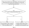
FIG. 2 shows a schematic flowchart of a control method according to the present invention. - The implementation of the present invention will be described in further detail below in combination with the accompanying drawings and embodiments. The detailed description of the following embodiments and the accompanying drawings are used to exemplarily illustrate the principles of the present invention, but cannot be used to limit the scope of the present invention, that is, the present invention is not limited to the described embodiments.
-
FIG. 1 shows a structural schematic diagram of an FOC-based control system. This control system is used in particular for a permanent magnet synchronous motor. Therefore, a permanent magnet synchronous motor is taken as an example of all of the motors mentioned below. As shown inFIG. 1 , the control system comprises: a motor, a motor rotational speed sensor module, a rotor position sensor module, a Clark transform module, a Park transform module, a first feedback module, a second feedback module, a first controller module, a second controller module, an inverse Park transform module, and an inverse Clark transform module, wherein the first controller module and the second controller module constitute acontrol module 10 according to the present invention. - An input end of the motor rotational speed sensor module is connected to the motor, and an output end of the motor rotational speed sensor module is connected to the first controller module and the second controller module, respectively. Therefore, the motor rotational speed sensor module may obtain a motor rotational speed of the motor, and output the same to the first controller module and the second controller module.
- An input end of the rotor position sensor module is connected to the motor, and an output end of the rotor position sensor module is connected to the Park transform module and the inverse Park transform module. Therefore, the rotor position sensor module may obtain an angular position of a rotor of the motor, and output the same to the Park transform module and the inverse Park transform module.
- An input end of the Clark transform module is connected to the motor, and may obtain three-phase stator currents ia, ib and ic of the motor. The three-phase stator currents ia, ib and ic are based on a natural coordinate system with a stator as a reference object, and satisfy the following relational expression according to Kirchhoff's current law:


- An output end of the Clark transform module is connected to an input end of the Park transform module, and therefore the Park transform module may transform the current components iα and iβ in the αβ coordinate system into an actual direct-axis current id and an actual quadrature-axis current iq in a dq coordinate system, which rotates relative to the stator but is stationary relative to the rotor, on the basis of a position angle θ of the rotor received from the rotor position sensor module and according to the following relational expressions:


- An output end of the Park transform module is connected to the first feedback module and the second feedback module, respectively, such that the actual quadrature-axis current iq and the actual direct-axis current id are output to the first feedback module and the second feedback module, respectively.
- In addition, an input end of the first feedback module is further connected to an external input to obtain a preset target quadrature-axis current iq_Ref, and therefore the first feedback module may compare the actual quadrature-axis current iq with the target quadrature-axis current iq_Ref, and can calculate a first difference value between the actual quadrature-axis current iq and the target quadrature-axis current iq_Ref.
- Similarly, an input end of the second feedback module is also connected to the external input to obtain a preset target direct-axis current id_Ref, and therefore the second feedback module may compare the actual direct-axis current id with the target direct-axis current id_Ref, and can calculate a second difference value between the actual direct-axis current id and the target direct-axis current id_Ref.
- The first controller module and the second controller module are connected to the output end of the motor rotational speed sensor module, respectively, to obtain an actual motor rotational speed. In addition, the first controller module is connected to the first feedback module to receive the first difference value between the actual quadrature-axis current iq and the target quadrature-axis current iq_Ref, and the second controller module is connected to the second feedback module to receive the second difference value between the actual direct-axis current id and the target direct-axis current id_Ref. The first controller module and the second controller module constitute the
control module 10 of the present invention. - After receiving the actual motor rotational speed, the first controller module first determines whether the motor rotational speed is greater than or equal to a preset rotational speed threshold value. The rotational speed threshold value here is generally greater than or equal to a flux weakening rotational speed, preferably equal to 5 times a ratio of a preset resistance to a preset inductance in the permanent magnet synchronous motor. Different motors have different rotational speed threshold values, and therefore the rotational speed threshold values may be preset at factories.
- When the actual motor rotational speed is determined to be greater than or equal to the rotational speed threshold value, the motor is in a flux weakening state, the first controller module is configured to adjust a direct-axis voltage Ud according to the first difference value between the actual quadrature-axis current iq and the target quadrature-axis current iq_Ref. Specifically, the first controller module may be a proportional-integral-derivative (PID) controller, which can perform proportional-integral iteration on the first difference value between the actual quadrature-axis current iq and the target quadrature-axis current iq_Ref from the first feedback module so as to adjust the direct-axis voltage Ud.
- For example, when the actual motor rotational speed is greater than or equal to the rotational speed threshold value, if the first difference value between the actual quadrature-axis current iq and the target quadrature-axis current iq_Ref is less than 0, this means that the actual quadrature-axis current iq is less than the target quadrature-axis current iq_Ref, so in this case, the actual quadrature-axis current iq is required to be increased; and since the actual quadrature-axis current iq satisfies the above-mentioned expression (7) when the motor is in a flux weakening state, the direct-axis voltage Ud is required to be reduced in order to increase the actual quadrature-axis current iq. Therefore, when the motor rotational speed is greater than or equal to the rotational speed threshold value, if the first difference value between the actual quadrature-axis current iq and the target quadrature-axis current iq_Ref is less than 0, the first controller module is configured to reduce the direct-axis voltage Ud. Conversely, when the motor rotational speed is greater than or equal to the rotational speed threshold value, if the first difference value between the actual quadrature-axis current iq and the target quadrature-axis current iq_Ref is greater than 0, this means that the actual quadrature-axis current iq is greater than the target quadrature-axis current iq_Ref, so in order to reduce the actual quadrature-axis current iq, it can be seen from the above-mentioned expression (7) that the first controller module is configured such that the direct-axis voltage Ud is required to be increased. Moreover, when the motor rotational speed is greater than or equal to the rotational speed threshold value, if the first difference value between the actual quadrature-axis current iq and the target quadrature-axis current iq_Ref is equal to 0, this means that the actual quadrature-axis current iq is equal to the target quadrature-axis current iq_Ref, so in this case, the first controller module is configured such that adjusting of the direct-axis voltage Ud is not required.
- Furthermore, when it is determined that the actual motor rotational speed is less than the rotational speed threshold value, the first controller module adjusts the quadrature-axis voltage Uq according to the quadrature-axis current iq. Similarly, the first controller module may perform proportional-integral iteration on the first difference value between the actual quadrature-axis current iq and the target quadrature-axis current iq_Ref from the first feedback module so as to adjust the quadrature-axis voltage Uq.
- For example, when the actual motor rotational speed is less than the rotational speed threshold value, if the first difference value between the actual quadrature-axis current iq and the target quadrature-axis current iq_Ref is less than 0, this means that the actual quadrature-axis current iq is less than the target quadrature-axis current iq_Ref, so in this case, the actual quadrature-axis current iq is required to be increased; and in this case, since the quadrature-axis current iq satisfies the above-mentioned expression (2), the quadrature-axis voltage Uq is required to be increased in order to increase the actual quadrature-axis current iq. Therefore, when the motor rotational speed is less than the rotational speed threshold value, if the first difference value between the actual quadrature-axis current iq and the target quadrature-axis current iq_Ref is less than 0, the first controller module is configured to increase the quadrature-axis voltage Uq. Conversely, when the motor rotational speed is less than the rotational speed threshold value, if the first difference value between the actual quadrature-axis current iq and the target quadrature-axis current iq_Ref is greater than 0, this means that the actual quadrature-axis current iq is greater than the target quadrature-axis current iq_Ref, so in order to reduce the actual quadrature-axis current iq, it can be seen from the above-mentioned expression (2) that the first controller module is configured such that the quadrature-axis voltage Uq is required to be reduced.
- Similarly, after receiving the actual motor rotational speed, the second controller module also first determines whether the motor rotational speed is greater than or equal to the preset rotational speed threshold value. When the actual motor rotational speed is determined to be greater than or equal to the rotational speed threshold value, the second controller module is configured to adjust the quadrature-axis voltage Uq according to the second difference value between the actual direct-axis current id and the target direct-axis current id_Ref. Specifically, the second controller module may be a PID controller, which can perform proportional-integral iteration on the second difference value between the actual direct-axis current id and the target direct-axis current id_Ref from the second feedback module so as to adjust the quadrature-axis voltage Uq.
- For example, when the actual motor rotational speed is greater than or equal to the rotational speed threshold value, if the second difference value between the actual direct-axis current id and the target direct-axis current id_Ref is less than 0, this means that the actual direct-axis current id is less than the target direct-axis current id_Ref, so in this case the actual direct-axis current id is required to be increased; and since the actual direct-axis current id satisfies the above-mentioned expression (8) when the motor is in a flux weakening state, the quadrature-axis voltage Uq is required to be increased in order to increase the actual direct-axis current id. Therefore, when the motor rotational speed is greater than or equal to the rotational speed threshold value, if the second difference value between the actual direct-axis current id and the target direct-axis current id_Ref is less than 0, the second controller module is configured to increase the quadrature-axis voltage Uq. Conversely, when the motor rotational speed is greater than or equal to the rotational speed threshold value, if the second difference value between the actual direct-axis current id and the target direct-axis current id_Ref is greater than 0, this means that the actual direct-axis current id is greater than the target direct-axis current id_Ref, so in order to reduce the actual direct-axis current id, it can be seen from the above-mentioned expression (8) that the second controller module is configured such that the quadrature-axis voltage Uq is required to be reduced. Moreover, when the motor rotational speed is greater than or equal to the rotational speed threshold value, if the second difference value between the actual direct-axis current id and the target direct-axis current id _Ref is equal to 0, this means that the actual direct-axis current id is equal to the target direct-axis current id_Ref, so in this case the second controller module is configured such that adjusting of the quadrature-axis voltage Uq is not required.
- Furthermore, when the actual motor rotational speed is determined to be less than the rotational speed threshold value, the second controller module adjusts the direct-axis voltage Ud according to the direct-axis current id. Similarly, the second controller module may perform proportional-integral iteration on the second difference value between the actual direct-axis current id and the target direct-axis current id_Ref from the second feedback module so as to adjust the direct-axis voltage Ud.
- For example, when the actual motor rotational speed is less than the rotational speed threshold value, if the second difference value between the actual direct-axis current id and the target direct-axis current id_Ref is less than 0, this means that the actual direct-axis current id is less than the target direct-axis current id_Ref, so in this case, the actual direct-axis current id is required to be increased; and in this case, since the direct-axis current id satisfies the above-mentioned expression (1), the direct-axis voltage Ud is required to be increased in order to increase the actual direct-axis current id. Therefore, when the motor rotational speed is less than the rotational speed threshold value, if the second difference value between the actual direct-axis current id and the target direct-axis current id_Ref is less than 0, the second controller module is configured to increase the direct-axis voltage Ud. Conversely, when the motor rotational speed is less than the rotational speed threshold value, if the second difference value between the actual direct-axis current id and the target direct-axis current id_Ref is greater than 0, this means that the actual quadrature-axis current iq is greater than the target quadrature-axis current iq_Ref, and it can be seen from the above-mentioned expression (1) that the second controller module is configured such that the direct-axis voltage Ud is required to be reduced.
- Subsequently, the first controller module and a second controller are connected to the inverse Park transform module, respectively, and therefore the adjusted direct-axis voltage Ud and quadrature-axis voltage Uq may be output to the inverse Park transform module. Then, the inverse Park transform module may transform the direct-axis voltage Ud and the quadrature-axis voltage Uq in the dq coordinate system to voltage components Uα and Uβ in the αβ coordinate system on the basis of the position angle θ of the rotor received from the rotor position sensor module and according to the following relational expressions:


- The inverse Park transform module is connected to the inverse Clark transform module, and therefore the voltage components Uα and Uβ in the αβ coordinate system may be output to the inverse Clark transform module. Then, the inverse Clark transform module may transform the voltage components Uα and Uβ in the αβ coordinate system into three-phase voltage values Ua, Ub and Uc in the natural coordinate system, and then output the three-phase voltage values Ua, Ub and Uc to the motor.
- After receiving the adjusted three-phase voltage values Ua, Ub and Uc, the motor outputs the three-phase stator currents ia, ib and ic again, and the control system may execute the above-mentioned control again according to the output three-phase stator currents ia, ib and ic again such that the difference value between the actual direct-axis current id and the target direct-axis current id_Ref and the difference value between the actual quadrature-axis current iq and the target quadrature-axis current iq_Ref are small, thereby facilitating the outputting of a more stable torque by the motor.
- Accordingly, the above-mentioned FOC-based control system may perform Clark transform, Park transform, PID control, inverse Park transform and inverse Clark transform on a current of the motor, respectively, such that the actual current of the motor is closer to a target current, thereby controlling the motor to output a constant electromagnetic torque, ensuring that the torque generated per unit stator current is maximized, and greatly improving motor efficiency.
- In particular, the control module according to the present invention may directly control the direct-axis voltage Ud and the quadrature-axis voltage Uq for different motor rotational speed values, that is, when the motor rotational speed is greater than or equal to the preset rotational speed threshold value, the PID controller adjusts the direct-axis voltage Ud according to the quadrature-axis current iq and adjusts the quadrature-axis voltage Uq according to the direct-axis current id, and when the motor rotational speed is less than the rotational speed threshold value, the PID controller adjusts the quadrature-axis voltage Uq according to the quadrature-axis current iq and adjusts the direct-axis voltage Ud according to the direct-axis current id. Accordingly, regardless of the motor rotational speed, the control module according to the present invention may more directly and quickly adjust the direct-axis voltage Ud and the quadrature-axis voltage Uq such that the direct-axis current id and quadrature-axis current iq output the next time by the motor are closer to the target direct-axis current id_Ref and the target quadrature-axis current iq_Ref, thereby ensuring that the direct-axis current id and quadrature-axis current iq output each time have low fluctuation at any motor speed, and thereby more effectively facilitating the outputting of a constant electromagnetic torque by the motor.
- Furthermore, the control module according to the present invention may be implemented by computer software modules, and functional modules and module units comprised therein can all correspond to specific hardware circuits in an integrated circuit structure; and owing to this solving the corresponding technical problems and obtaining the corresponding technical effects involve not only improvements of the specific hardware circuits, but also applications of control software or computer programs, that is, the present invention may use improvements in the hardware circuit structures involved in these modules and units and improvements of corresponding computer programs to solve the technical problem to be solved and obtain the corresponding technical effects.
- The control method according to the present invention is described below with reference to the flowchart in
FIG. 2 , wherein the control method is implemented by the above-mentionedcontrol module 10, which comprises the first controller module and the second controller module. As shown inFIG. 2 , in step S210, the motor rotational speed, the first difference value between the actual quadrature-axis current iq and the target quadrature-axis current iq_Ref, and a second difference between the actual direct-axis current id and the target direct-axis current id_Ref are obtained. In step S220, whether the motor rotational speed is greater than or equal to the preset rotational speed threshold value is determined. - If it is determined in step S220 that the motor rotational speed is greater than or equal to the rotational speed threshold value, the direct-axis voltage Ud is adjusted by the first controller module according to the first difference value, and the quadrature-axis voltage Uq is adjusted by the second controller module according to the second difference value (i.e., step S230). If it is determined in step S220 that the motor rotational speed is less than the rotational speed threshold value, the quadrature-axis voltage Uq is adjusted by the first controller module according to the first difference value, and the direct-axis voltage Ud is adjusted by the second controller module according to the second difference value (i.e., step S240). For the specific adjustment process, refer to the above descriptions of the first controller module and the second controller module. The specifics thereof are omitted below.
- Accordingly, regardless of the rotational speed at which the motor rotates, the control method according to the present invention may more directly and quickly adjust the direct-axis voltage Ud and the quadrature-axis voltage Uq such that the direct-axis current id and quadrature-axis current iq output the next time by the motor are closer to the target direct-axis current id_Ref and the target quadrature-axis current iq_Ref, thereby ensuring that the direct-axis current id and quadrature-axis current iq output each time have low fluctuation at any motor speed, and thereby more effectively facilitating the outputting of a constant electromagnetic torque by the motor.
- Although the present invention has been described with reference to the preferred embodiments, various improvements can be made and components therein may be replaced with equivalents without departing from the scope of the present invention, and in particular, as long as there is no structural conflict, the technical features mentioned in the embodiments may be combined in any way. The present invention is not limited to the specific embodiments disclosed herein, but shall include all technical solutions falling within the scope of the claims.
Claims (10)
- A control method for a permanent magnet synchronous motor, comprising the following steps:obtaining a motor rotational speed, a first difference value between an actual quadrature-axis current iq and a target quadrature-axis current iq_Ref, and a second difference value between an actual direct-axis current id and a target direct-axis current id_Ref;determining whether or not the motor rotational speed is greater than or equal to a preset rotational speed threshold value; andadjusting a direct-axis voltage Ud according to the first difference value and adjusting a quadrature-axis voltage Uq according to the second difference value when the motor rotational speed is greater than or equal to the rotational speed threshold value.
- The control method according to Claim 1, wherein,
when the motor rotational speed is greater than or equal to the rotational speed threshold value, if the first difference value between the actual quadrature-axis current iq and the target quadrature-axis current iq_Ref is less than 0, the direct-axis voltage Ud is reduced; otherwise the direct-axis voltage Ud is increased. - The control method according to Claim 1, wherein,
when the motor rotational speed is greater than or equal to the rotational speed threshold value, if the second difference value between the actual direct-axis current id and the target direct-axis current id_Ref is less than 0, the quadrature-axis voltage Uq is increased; otherwise the quadrature-axis voltage Uq is reduced. - The control method according to Claim 1, further comprising the following steps:
adjusting the quadrature-axis voltage Uq according to the first difference value and adjusting the direct-axis voltage Ud according to the second difference value when the motor rotational speed is less than the rotational speed threshold value. - The control method according to Claim 4, wherein,
when the motor rotational speed is less than the rotational speed threshold value, if the first difference value between the actual quadrature-axis current iq and the target quadrature-axis current iq_Ref is less than 0, the quadrature-axis voltage Uq is increased; otherwise the quadrature-axis voltage Uq is reduced. - The control method according to Claim 4, wherein,
when the motor rotational speed is less than the rotational speed threshold value, if the second difference value between the actual direct-axis current id and the target direct-axis current id_Ref is less than 0, the direct-axis voltage Ud is increased; otherwise the direct-axis voltage Ud is reduced. - The control method according to any one of Claims 1 to 6, wherein
the rotational speed threshold value is 5 times the ratio of a preset resistance to a preset inductance in the permanent magnet synchronous motor. - A control module for a permanent magnet synchronous motor, comprising a first controller module and a second controller module, wherein
the first controller module is configured to:obtain a motor rotational speed and a first difference value between an actual quadrature-axis current iq and a target quadrature-axis current iq_Ref;determine whether or not the motor rotational speed is greater than or equal to a preset rotational speed threshold value; andadjust the direct-axis voltage Ud according to the first difference value when the motor rotational speed is greater than or equal to the rotational speed threshold value; andthe second controller module is configured to:obtain the motor rotational speed and a second difference value between an actual direct-axis current id and a target direct-axis current id_Ref,determine whether or not the motor rotational speed is greater than or equal to the rotational speed threshold value; andadjust the quadrature-axis voltage Uq according to the second difference value when the motor rotational speed is greater than or equal to the rotational speed threshold value. - The control module according to Claim 8, whereinthe first controller module is configured to: when the motor rotational speed is greater than or equal to the rotational speed threshold value, if the first difference value is less than 0, reduce the direct-axis voltage Ud, or otherwise increase the direct-axis voltage Ud; andthe second controller module is configured to: when the motor rotational speed is greater than or equal to the rotational speed threshold value, if the second difference value is less than 0, increase the quadrature-axis voltage Uq, or otherwise reduce the quadrature-axis voltage Uq.
- The control module according to Claim 8 or 9, wherein
the first controller module is configured to: adjust the quadrature-axis voltage Uq according to the first difference value when the motor rotational speed is less than the rotational speed threshold value; and the second controller module is configured to: adjust the direct-axis voltage Ud according to the second difference value.
Applications Claiming Priority (2)
| Application Number | Priority Date | Filing Date | Title |
|---|---|---|---|
| CN202210031645.6A CN116470794A (en) | 2022-01-12 | 2022-01-12 | Control method and control module for permanent magnet synchronous motor |
| PCT/CN2022/138927 WO2023134379A1 (en) | 2022-01-12 | 2022-12-14 | Control method for permanent magnet synchronous motor, and control module |
Publications (2)
| Publication Number | Publication Date |
|---|---|
| EP4465519A1 true EP4465519A1 (en) | 2024-11-20 |
| EP4465519A4 EP4465519A4 (en) | 2026-01-07 |
Family
ID=87181179
Family Applications (1)
| Application Number | Title | Priority Date | Filing Date |
|---|---|---|---|
| EP22920011.8A Pending EP4465519A4 (en) | 2022-01-12 | 2022-12-14 | CONTROL METHOD FOR A PERMANENT MAGNETIC SYNC MOTOR AND CONTROL MODULE |
Country Status (4)
| Country | Link |
|---|---|
| US (1) | US20250070699A1 (en) |
| EP (1) | EP4465519A4 (en) |
| CN (1) | CN116470794A (en) |
| WO (1) | WO2023134379A1 (en) |
Families Citing this family (1)
| Publication number | Priority date | Publication date | Assignee | Title |
|---|---|---|---|---|
| CN117048364A (en) * | 2023-09-05 | 2023-11-14 | 中国第一汽车股份有限公司 | Torque control method, device, storage medium and electronic device for vehicle |
Family Cites Families (6)
| Publication number | Priority date | Publication date | Assignee | Title |
|---|---|---|---|---|
| JP4754378B2 (en) * | 2006-03-22 | 2011-08-24 | 本田技研工業株式会社 | Electric motor control device |
| CN107046386B (en) * | 2017-04-17 | 2020-04-07 | 南京越博动力系统股份有限公司 | Novel method for weak magnetic calibration of permanent magnet synchronous motor controller of pure electric vehicle |
| CN107404273A (en) * | 2017-06-20 | 2017-11-28 | 奥克斯空调股份有限公司 | A kind of permagnetic synchronous motor current decoupling control method |
| CN109873590A (en) * | 2019-04-09 | 2019-06-11 | 湘潭大学 | A field weakening speed expansion method of an embedded permanent magnet synchronous motor for electric vehicles |
| CN110518850A (en) * | 2019-09-12 | 2019-11-29 | 桂林电子科技大学 | Internal permanent magnet synchronous motor single neuron self-adaptive PID controller field weakening control method |
| CN113241987B (en) * | 2021-05-11 | 2022-12-20 | 广东美的白色家电技术创新中心有限公司 | A motor control method, control system and storage medium |
-
2022
- 2022-01-12 CN CN202210031645.6A patent/CN116470794A/en active Pending
- 2022-12-14 EP EP22920011.8A patent/EP4465519A4/en active Pending
- 2022-12-14 WO PCT/CN2022/138927 patent/WO2023134379A1/en not_active Ceased
- 2022-12-14 US US18/726,418 patent/US20250070699A1/en active Pending
Also Published As
| Publication number | Publication date |
|---|---|
| WO2023134379A1 (en) | 2023-07-20 |
| EP4465519A4 (en) | 2026-01-07 |
| CN116470794A (en) | 2023-07-21 |
| US20250070699A1 (en) | 2025-02-27 |
Similar Documents
| Publication | Publication Date | Title |
|---|---|---|
| EP1748550B1 (en) | Synchronous machine controller | |
| US6965212B1 (en) | Method and apparatus for field weakening control in an AC motor drive system | |
| US6407531B1 (en) | Method and system for controlling a synchronous machine over full operating range | |
| US6329781B1 (en) | Control apparatus of synchronous motors | |
| US8106618B2 (en) | Method and device for calibrating a position sensor placed on a shaft of a permanent magnet synchronous motor | |
| JP6008264B2 (en) | Magnetic pole position detection device for permanent magnet type synchronous motor | |
| CN100468946C (en) | Lead angle control method and device for permanent magnet synchronous motor operating in field weakening area | |
| US10411632B2 (en) | Alternator with harmonic compensation | |
| JP2008109850A (en) | Method and system for controlling synchronous motor drive system | |
| US6806676B2 (en) | Method for maximizing power output in permanent field synchronous motors | |
| Moazen et al. | Model-based predictive direct power control of brushless doubly fed reluctance generator for wind power applications | |
| US20220311367A1 (en) | Control method for vector flux weakening for vehicle permanent magnet synchronous motor | |
| US20250070699A1 (en) | Control method for permanent magnet synchronous motor, and control module | |
| US9240744B2 (en) | Methods, systems and apparatus for adjusting current and/or torque commands used to control operation of an asynchronous machine | |
| TW201817153A (en) | Synchronous motor control circuit and control method | |
| CN106849769A (en) | Motor driven systems based on sliding mode observer | |
| CN206712688U (en) | Motor driven systems based on sliding mode observer | |
| Liu et al. | Impact of Position Measurement Angle Error on Performance of PMSM Drives for Electric Power Steering in a Wide Speed Range | |
| Wang et al. | Direct look-up table method for field-weakening control of permanent magnet synchronous motor based on operation conditions | |
| Matic et al. | Voltage angle direct torque control of induction machine in field-weakening regime | |
| Matić et al. | Induction motor torque control in field weakening regime by voltage angle control | |
| US20250364933A1 (en) | Method, controller and computer program for operating an inverter, and inverter system | |
| US12261552B2 (en) | Method for controlling a rectifier connected to a permanent-magnet synchronous electric generator to provide a direct voltage, corresponding device and computer program | |
| CN111224595A (en) | Motor control method and device for improving safety, compressor and air conditioner | |
| CN115313948B (en) | Current hysteresis control method, device and electronic equipment for permanent magnet synchronous motor |
Legal Events
| Date | Code | Title | Description |
|---|---|---|---|
| STAA | Information on the status of an ep patent application or granted ep patent |
Free format text: STATUS: THE INTERNATIONAL PUBLICATION HAS BEEN MADE |
|
| PUAI | Public reference made under article 153(3) epc to a published international application that has entered the european phase |
Free format text: ORIGINAL CODE: 0009012 |
|
| STAA | Information on the status of an ep patent application or granted ep patent |
Free format text: STATUS: REQUEST FOR EXAMINATION WAS MADE |
|
| 17P | Request for examination filed |
Effective date: 20240812 |
|
| AK | Designated contracting states |
Kind code of ref document: A1 Designated state(s): AL AT BE BG CH CY CZ DE DK EE ES FI FR GB GR HR HU IE IS IT LI LT LU LV MC ME MK MT NL NO PL PT RO RS SE SI SK SM TR |
|
| DAV | Request for validation of the european patent (deleted) | ||
| DAX | Request for extension of the european patent (deleted) | ||
| REG | Reference to a national code |
Ref country code: DE Ref legal event code: R079 Free format text: PREVIOUS MAIN CLASS: H02P0006280000 Ipc: H02P0021180000 |
|
| A4 | Supplementary search report drawn up and despatched |
Effective date: 20251205 |
|
| RIC1 | Information provided on ipc code assigned before grant |
Ipc: H02P 21/18 20160101AFI20251201BHEP Ipc: H02P 25/022 20160101ALI20251201BHEP |