EP4465472A1 - Photovoltaic inverter and control method thereof, and photovoltaic system - Google Patents
Photovoltaic inverter and control method thereof, and photovoltaic system Download PDFInfo
- Publication number
- EP4465472A1 EP4465472A1 EP24167325.0A EP24167325A EP4465472A1 EP 4465472 A1 EP4465472 A1 EP 4465472A1 EP 24167325 A EP24167325 A EP 24167325A EP 4465472 A1 EP4465472 A1 EP 4465472A1
- Authority
- EP
- European Patent Office
- Prior art keywords
- power
- time period
- inverter
- inverter circuit
- output power
- Prior art date
- Legal status (The legal status is an assumption and is not a legal conclusion. Google has not performed a legal analysis and makes no representation as to the accuracy of the status listed.)
- Pending
Links
Images


Classifications
-
- H—ELECTRICITY
- H02—GENERATION; CONVERSION OR DISTRIBUTION OF ELECTRIC POWER
- H02J—ELECTRIC POWER NETWORKS; CIRCUIT ARRANGEMENTS OR SYSTEMS FOR SUPPLYING OR DISTRIBUTING ELECTRIC POWER; SYSTEMS FOR STORING ELECTRIC ENERGY
- H02J3/00—Circuit arrangements for AC mains or AC distribution networks
- H02J3/38—Arrangements for feeding a single network from two or more generators or sources in parallel; Arrangements for feeding already energised networks from additional generators or sources in parallel
-
- H—ELECTRICITY
- H02—GENERATION; CONVERSION OR DISTRIBUTION OF ELECTRIC POWER
- H02J—ELECTRIC POWER NETWORKS; CIRCUIT ARRANGEMENTS OR SYSTEMS FOR SUPPLYING OR DISTRIBUTING ELECTRIC POWER; SYSTEMS FOR STORING ELECTRIC ENERGY
- H02J3/00—Circuit arrangements for AC mains or AC distribution networks
- H02J3/38—Arrangements for feeding a single network from two or more generators or sources in parallel; Arrangements for feeding already energised networks from additional generators or sources in parallel
- H02J3/381—Dispersed generators
-
- H—ELECTRICITY
- H02—GENERATION; CONVERSION OR DISTRIBUTION OF ELECTRIC POWER
- H02J—ELECTRIC POWER NETWORKS; CIRCUIT ARRANGEMENTS OR SYSTEMS FOR SUPPLYING OR DISTRIBUTING ELECTRIC POWER; SYSTEMS FOR STORING ELECTRIC ENERGY
- H02J3/00—Circuit arrangements for AC mains or AC distribution networks
- H02J3/28—Arrangements for balancing of the load in networks by storage of energy
-
- H—ELECTRICITY
- H02—GENERATION; CONVERSION OR DISTRIBUTION OF ELECTRIC POWER
- H02J—ELECTRIC POWER NETWORKS; CIRCUIT ARRANGEMENTS OR SYSTEMS FOR SUPPLYING OR DISTRIBUTING ELECTRIC POWER; SYSTEMS FOR STORING ELECTRIC ENERGY
- H02J3/00—Circuit arrangements for AC mains or AC distribution networks
- H02J3/28—Arrangements for balancing of the load in networks by storage of energy
- H02J3/32—Arrangements for balancing of the load in networks by storage of energy using batteries or super capacitors with converting means
-
- H—ELECTRICITY
- H02—GENERATION; CONVERSION OR DISTRIBUTION OF ELECTRIC POWER
- H02J—ELECTRIC POWER NETWORKS; CIRCUIT ARRANGEMENTS OR SYSTEMS FOR SUPPLYING OR DISTRIBUTING ELECTRIC POWER; SYSTEMS FOR STORING ELECTRIC ENERGY
- H02J3/00—Circuit arrangements for AC mains or AC distribution networks
- H02J3/38—Arrangements for feeding a single network from two or more generators or sources in parallel; Arrangements for feeding already energised networks from additional generators or sources in parallel
- H02J3/46—Controlling the sharing of generated power between the generators, sources or networks
- H02J3/466—Scheduling or selectively controlling the operation of the generators or sources, e.g. connecting or disconnecting generators to meet a demand
-
- H—ELECTRICITY
- H02—GENERATION; CONVERSION OR DISTRIBUTION OF ELECTRIC POWER
- H02J—ELECTRIC POWER NETWORKS; CIRCUIT ARRANGEMENTS OR SYSTEMS FOR SUPPLYING OR DISTRIBUTING ELECTRIC POWER; SYSTEMS FOR STORING ELECTRIC ENERGY
- H02J7/00—Circuit arrangements for charging or discharging batteries or for supplying loads from batteries
- H02J7/34—Parallel operation in networks using both storage and other DC sources, e.g. providing buffering
- H02J7/35—Parallel operation in networks using both storage and other DC sources, e.g. providing buffering with light sensitive cells
-
- H—ELECTRICITY
- H02—GENERATION; CONVERSION OR DISTRIBUTION OF ELECTRIC POWER
- H02J—ELECTRIC POWER NETWORKS; CIRCUIT ARRANGEMENTS OR SYSTEMS FOR SUPPLYING OR DISTRIBUTING ELECTRIC POWER; SYSTEMS FOR STORING ELECTRIC ENERGY
- H02J7/00—Circuit arrangements for charging or discharging batteries or for supplying loads from batteries
- H02J7/865—Battery or charger load switching, e.g. concurrent charging and load supply
-
- H—ELECTRICITY
- H02—GENERATION; CONVERSION OR DISTRIBUTION OF ELECTRIC POWER
- H02M—APPARATUS FOR CONVERSION BETWEEN AC AND AC, BETWEEN AC AND DC, OR BETWEEN DC AND DC, AND FOR USE WITH MAINS OR SIMILAR POWER SUPPLY SYSTEMS; CONVERSION OF DC OR AC INPUT POWER INTO SURGE OUTPUT POWER; CONTROL OR REGULATION THEREOF
- H02M1/00—Details of apparatus for conversion
- H02M1/0067—Converter structures employing plural converter units, other than for parallel operation of the units on a single load
-
- H—ELECTRICITY
- H02—GENERATION; CONVERSION OR DISTRIBUTION OF ELECTRIC POWER
- H02M—APPARATUS FOR CONVERSION BETWEEN AC AND AC, BETWEEN AC AND DC, OR BETWEEN DC AND DC, AND FOR USE WITH MAINS OR SIMILAR POWER SUPPLY SYSTEMS; CONVERSION OF DC OR AC INPUT POWER INTO SURGE OUTPUT POWER; CONTROL OR REGULATION THEREOF
- H02M3/00—Conversion of DC power input into DC power output
- H02M3/02—Conversion of DC power input into DC power output without intermediate conversion into AC
- H02M3/04—Conversion of DC power input into DC power output without intermediate conversion into AC by static converters
-
- H—ELECTRICITY
- H02—GENERATION; CONVERSION OR DISTRIBUTION OF ELECTRIC POWER
- H02M—APPARATUS FOR CONVERSION BETWEEN AC AND AC, BETWEEN AC AND DC, OR BETWEEN DC AND DC, AND FOR USE WITH MAINS OR SIMILAR POWER SUPPLY SYSTEMS; CONVERSION OF DC OR AC INPUT POWER INTO SURGE OUTPUT POWER; CONTROL OR REGULATION THEREOF
- H02M7/00—Conversion of AC power input into DC power output; Conversion of DC power input into AC power output
- H02M7/42—Conversion of DC power input into AC power output without possibility of reversal
- H02M7/44—Conversion of DC power input into AC power output without possibility of reversal by static converters
-
- H—ELECTRICITY
- H02—GENERATION; CONVERSION OR DISTRIBUTION OF ELECTRIC POWER
- H02M—APPARATUS FOR CONVERSION BETWEEN AC AND AC, BETWEEN AC AND DC, OR BETWEEN DC AND DC, AND FOR USE WITH MAINS OR SIMILAR POWER SUPPLY SYSTEMS; CONVERSION OF DC OR AC INPUT POWER INTO SURGE OUTPUT POWER; CONTROL OR REGULATION THEREOF
- H02M7/00—Conversion of AC power input into DC power output; Conversion of DC power input into AC power output
- H02M7/42—Conversion of DC power input into AC power output without possibility of reversal
- H02M7/44—Conversion of DC power input into AC power output without possibility of reversal by static converters
- H02M7/48—Conversion of DC power input into AC power output without possibility of reversal by static converters using discharge tubes with control electrode or semiconductor devices with control electrode
- H02M7/483—Converters with outputs that each can have more than two voltages levels
-
- H—ELECTRICITY
- H02—GENERATION; CONVERSION OR DISTRIBUTION OF ELECTRIC POWER
- H02J—ELECTRIC POWER NETWORKS; CIRCUIT ARRANGEMENTS OR SYSTEMS FOR SUPPLYING OR DISTRIBUTING ELECTRIC POWER; SYSTEMS FOR STORING ELECTRIC ENERGY
- H02J2101/00—Supply or distribution of decentralised, dispersed or local electric power generation
- H02J2101/20—Dispersed power generation using renewable energy sources
- H02J2101/22—Solar energy
- H02J2101/24—Photovoltaics
-
- H—ELECTRICITY
- H02—GENERATION; CONVERSION OR DISTRIBUTION OF ELECTRIC POWER
- H02J—ELECTRIC POWER NETWORKS; CIRCUIT ARRANGEMENTS OR SYSTEMS FOR SUPPLYING OR DISTRIBUTING ELECTRIC POWER; SYSTEMS FOR STORING ELECTRIC ENERGY
- H02J2101/00—Supply or distribution of decentralised, dispersed or local electric power generation
- H02J2101/20—Dispersed power generation using renewable energy sources
- H02J2101/22—Solar energy
- H02J2101/24—Photovoltaics
- H02J2101/25—Photovoltaics involving maximum power point tracking control for photovoltaic sources
-
- Y—GENERAL TAGGING OF NEW TECHNOLOGICAL DEVELOPMENTS; GENERAL TAGGING OF CROSS-SECTIONAL TECHNOLOGIES SPANNING OVER SEVERAL SECTIONS OF THE IPC; TECHNICAL SUBJECTS COVERED BY FORMER USPC CROSS-REFERENCE ART COLLECTIONS [XRACs] AND DIGESTS
- Y02—TECHNOLOGIES OR APPLICATIONS FOR MITIGATION OR ADAPTATION AGAINST CLIMATE CHANGE
- Y02E—REDUCTION OF GREENHOUSE GAS [GHG] EMISSIONS, RELATED TO ENERGY GENERATION, TRANSMISSION OR DISTRIBUTION
- Y02E10/00—Energy generation through renewable energy sources
- Y02E10/50—Photovoltaic [PV] energy
- Y02E10/56—Power conversion systems, e.g. maximum power point trackers
Definitions
- This application relates to the field of power electronics technologies, and in particular, to a photovoltaic inverter and a control method thereof, and a photovoltaic system.
- an inverter circuit in a photovoltaic inverter is usually used to convert direct current electric energy into alternating current electric energy, so that the electric energy is transmitted between a power supply (for example, a photovoltaic module) and a load.
- a power supply for example, a photovoltaic module
- the photovoltaic inverter usually needs to adjust a supply power (for example, an output power) based on a power supply capability of the photovoltaic module, so that a voltage conversion circuit works at a maximum power point. This process is referred to as maximum power point tracking (Maximum Power Point Tracking, MPPT).
- MPPT Maximum Power Point Tracking
- the photovoltaic inverter may be further connected to an energy storage unit.
- the photovoltaic inverter herein may convert a part of direct current electric energy output by the photovoltaic module into alternating current electric energy, provide the alternating current electric energy for the load or a power grid to use, and store, in the energy storage unit, the other part of direct current electric energy output by the photovoltaic module.
- the conventional technology has the following disadvantages: when the photovoltaic inverter charges the energy storage unit at a full power or when the energy storage unit is in a full-charged state, if the photovoltaic inverter needs to increase an output power of the inverter circuit in a maximum power point tracking process, a charge power of the energy storage unit may be decreased or the energy storage unit may change from charging to discharging.
- the inverter or a control module of the inverter detects that the energy storage unit is charged at a lower power or the energy storage unit is in a discharge state, and decreases an output power of the inverter.
- This control method may cause the energy storage unit to repeatedly switch between a charge state and the discharge state, or cause a system grid-connected power to repeatedly fluctuate, and consequently, the inverter cannot stably work at a maximum power point. This increases power supply costs, and has poor adaptability.
- This application provides a photovoltaic inverter and a control method thereof, and a photovoltaic system, to prevent a decrease of a bus voltage in a process of increasing an output power of an inverter circuit by the photovoltaic system based on an excessively large step, improve stability of the bus voltage, stably increase an output power of the inverter while ensuring stable operation of the inverter and safe use of a power component, and improve power supply efficiency of the photovoltaic system.
- this application provides a photovoltaic inverter.
- the photovoltaic inverter includes a voltage conversion circuit, an inverter circuit, and a controller.
- one end of the voltage conversion circuit may be configured to connect to a photovoltaic module
- the other end of the voltage conversion circuit may be configured to connect to one end of the inverter circuit
- the other end of the inverter circuit may be configured to connect to a power grid
- the inverter circuit and the power grid are connected to a grid-connected point.
- the voltage conversion circuit herein may be configured to output, to the inverter circuit, a direct current input by the photovoltaic module.
- the inverter circuit herein is configured to: receive the direct current output by the voltage conversion circuit, convert the received direct current output by the voltage conversion circuit into an alternating current, and output the alternating current to the power grid.
- the controller herein may be configured to increase, based on an output power of the inverter circuit in a current time period and an output power of the inverter circuit in a first time period, an output power of the inverter circuit when the voltage conversion circuit does not work in a maximum power state.
- an increase of the output power of the inverter circuit may be referred to as an estimated power increment value of the inverter circuit, and the estimated power increment value of the inverter circuit is in direct proportion to a difference between the output power in the current time period and the output power in the first time period.
- being in direct proportion may be a linear function relationship, or may be a positive correlation relationship of a non-linear function.
- the first time period is before the current time period.
- the photovoltaic module (or a photovoltaic string including a plurality of photovoltaic modules) may be used as a power supply to connect to the power grid by using the photovoltaic inverter, and the photovoltaic inverter may convert direct current electric energy provided by the photovoltaic module into alternating current electric energy, and provide the alternating current electric energy for the power grid.
- the photovoltaic inverter may include the voltage conversion circuit and the inverter circuit.
- the voltage conversion circuit may convert an output voltage of the photovoltaic module into a direct current voltage that matches the inverter circuit, and transmit the direct current voltage to the inverter circuit.
- the inverter circuit may convert direct current electric energy into alternating current electric energy, so that electric energy output by the inverter circuit can adapt to an alternating current power grid.
- the photovoltaic inverter may supply power by using a maximum power point tracking (Maximum Power Point Tracking, MPPT) technology, that is, control an output power of the inverter, to enable the photovoltaic module to work at a maximum power point, so that the inverter can output electric energy to the power grid at a maximum output power.
- MPPT Maximum Power Point Tracking
- MPPT Maximum Power Point Tracking
- the output power of the inverter may need to be increased according to a scheduling instruction.
- the maximum output power of the inverter is unknown when the inverter is in the non-MPPT state. In this case, the output power of the inverter is increased too much. As a result, the output power of the inverter exceeds a power output capability of the inverter. This may cause system breakdown.
- the controller may adjust the output power of the inverter based on the estimated power increment value.
- the output power of the inverter is determined by the output power of the inverter circuit in the inverter, and the output power of the inverter circuit is limited by an output power of the previous-stage voltage conversion circuit.
- a power output capability of the previous-stage voltage conversion circuit needs to be considered for the increase of the output power of the inverter, and the estimated power increment value herein may be obtained based on the output power of the inverter circuit in the current time period and the output power of the inverter circuit in the first time period.
- the controller may evaluate a capability of outputting electric energy by the voltage conversion circuit in the current time period based on the output power of the inverter circuit in the current time period and the output power of the inverter circuit in the first time period, to obtain an estimated power increment value of an appropriate magnitude, and adjust the output power of the inverter based on the estimated power increment value.
- the controller may obtain an estimated power increment value of an appropriate magnitude based on an output power of the inverter circuit between the current time period and the first time period, and adjust the output power of the inverter based on the estimated power increment value.
- the other end of the voltage conversion circuit may be configured to connect to an energy storage unit, and is configured to output, to the energy storage unit, a direct current input by the photovoltaic module.
- the inverter circuit herein may be configured to: receive the direct current output by the energy storage unit, convert the received direct current output by the energy storage unit into an alternating current, and output the alternating current to the power grid.
- the power grid side may require the photovoltaic inverter to increase an output power (for example, an equivalent load on the power grid side is increased, or a grid-connected power corresponding to a grid-connected standard on the power grid side is increased, or an electric power consumption power of a local load is increased), to increase the input power of the inverter circuit. If the output power of the inverter circuit is adjusted based on the excessively large adjustment step, the bus voltage may be decreased.
- the system discharges to the inverter circuit by using the energy storage unit, to increase the output power of the inverter circuit, or a charge power of the energy storage unit is decreased. Therefore, when the photovoltaic inverter or another controller in the photovoltaic system detects that the energy storage unit discharges to the inverter circuit by using the inverter circuit, or detects that the charge power of the energy storage unit is decreased, or detects that the bus voltage is decreased, the photovoltaic inverter or the another controller in the photovoltaic system may further adjust the inverter circuit to decrease the output power.
- This may cause the energy storage unit to repeatedly switch between a charge state and a discharge state, or cause a system grid-connected power to repeatedly fluctuate, or cause the bus voltage to repeatedly fluctuate, or cause the voltage conversion circuit to fail to stably work in the maximum power state. If the output power of the inverter circuit is adjusted based on an excessively small adjustment step, the system may track the maximum power point too slowly. In this case, power supply efficiency of the photovoltaic system is reduced.
- the controller may evaluate the capability of outputting electric energy by the voltage conversion circuit in the current time period based on the output power of the inverter circuit in the current time period and the output power of the inverter circuit in the first time period, to obtain an estimated power increment value of an appropriate magnitude, and adjust the output power of the inverter based on the estimated power increment value.
- the controller may obtain an estimated power increment value of an appropriate magnitude based on an output power of the inverter circuit between the current time period and the first time period, and adjust the output power of the inverter based on the estimated power increment value.
- the controller may be configured to: when the voltage conversion circuit does not work in the maximum power state, if the difference between the output power of the inverter circuit in the current time period and the output power of the inverter circuit in the first time period is less than a first threshold, set the estimated power increment value of the inverter circuit to a first power increment value.
- the controller may evaluate a capability of outputting electric energy by the voltage conversion circuit in the current time period based on a magnitude relationship between the first threshold and the difference between the output power of the inverter circuit in the current time period and the output power of the inverter circuit in the first time period, to obtain an estimated power increment value of an appropriate magnitude, and adjust the output power of the inverter based on the estimated power increment value.
- the difference between the output power in the current time period and the output power in the first time period is less than the first threshold, it is estimated that the capability of outputting electric energy by the voltage conversion circuit in the current time period is weak, so that a small estimated power increment value (for example, the first power increment value) is obtained, and the output power of the inverter is adjusted based on the estimated power increment value. That is, in the current time period, if the output power of the inverter is adjusted based on an estimated power increment value greater than the first power increment value, the charge power of the energy storage unit needs to be decreased or the energy storage unit needs to discharge for compensation.
- a small estimated power increment value for example, the first power increment value
- the first power increment value may be calculated in real time based on the power supply parameter of the inverter, the energy storage parameter of the energy storage unit, and/or the grid-connected parameter of the power grid in the application scenario, or may be calculated in real time based on an estimated power increment value (or based on another parameter that can indicate the capability of outputting electric energy by the voltage conversion circuit) of the inverter circuit in a previous time period or several previous time periods (for example, the first time period), or may be calculated in real time based on the current environment (for example, the parameter like the light intensity or the temperature).
- the first power increment value herein may be a power increment value, may be a plurality of discrete power increment values, or may be a power increment interval formed including a plurality of discrete power increment values or continuous power increment values.
- energy storage efficiency of the energy storage unit can be avoided from being sacrificed in a process of increasing the output power of the inverter circuit by the photovoltaic system, stability of the voltage conversion circuit working in the maximum power state can be improved, and power supply efficiency of the photovoltaic system can be improved.
- a structure is simple, a method is simple, and applicability is high.
- the controller may be further configured to: when the voltage conversion circuit does not work in the maximum power state, if the difference between the output power of the inverter circuit in the current time period and the output power of the inverter circuit in the first time period is greater than or equal to the first threshold, and a difference between the output power of the inverter circuit in the current time period and an output power of the inverter circuit in a second time period is less than a second threshold, set the estimated power increment value of the inverter circuit to a second power increment value, where the second time period is before the first time period, and the second power increment value is greater than the first power increment value.
- the controller may preliminarily evaluate the capability of receiving electric energy by the voltage conversion circuit in the current time period based on the magnitude relationship between the first threshold and the difference between the output power of the inverter circuit in the current time period and the output power of the inverter circuit in the first time period.
- the capability of receiving electric energy by the voltage conversion circuit (or outputting electric energy by the photovoltaic module) in the current time period is further evaluated based on a magnitude relationship between the difference between the output power of the inverter circuit in the current time period and the output power of the inverter circuit in the second time period and the second threshold, to obtain an estimated power increment value of an appropriate size, and adjust the output power of the inverter based on the estimated power increment value.
- the difference between the output power in the current time period and the output power in the first time period is greater than or equal to the first threshold, it is preliminarily estimated that the capability of outputting electric energy by the voltage conversion circuit in the current time period is strong, and a capability of receiving electric energy by the voltage conversion circuit (or outputting electric energy by the photovoltaic module) in the current time period may be further evaluated.
- the difference between the output power of the inverter circuit in the current time period and the output power of the inverter circuit in the second time period is less than the second threshold, it is further evaluated that the capability of receiving electric energy by the voltage conversion circuit (or outputting electric energy by the photovoltaic module) in the current time period is strong, to obtain an estimated power increment value (for example, the second power increment value) greater than the first power increment value, and adjust the output power of the inverter based on the estimated power increment value.
- an estimated power increment value for example, the second power increment value
- the output power of the inverter is adjusted based on an estimated power increment value less than the second power increment value, the capability of receiving electric energy by the voltage conversion circuit in the current time period is not fully used, and more time needs to be spent to enable the inverter to work in the maximum power state.
- the inverter in the current time period, if the output power of the inverter is adjusted based on the second power increment value, the inverter can quickly work in the maximum power state while ensuring the charge power of the energy storage unit (or ensuring that the energy storage unit does not discharge), and more efficiently convert a part of the direct current electric energy generated by the power supply (for example, the photovoltaic module) into alternating current electric energy and provide the alternating current electric energy for the power grid.
- the second power increment value is greater than the first power increment value.
- the second power increment value may be calculated in real time based on the power supply parameter of the inverter, the energy storage parameter of the energy storage unit, and/or the grid-connected parameter of the power grid in the application scenario, or may be calculated in real time based on an estimated power increment value (or based on another parameter that can indicate the capability of outputting electric energy by the voltage conversion circuit) of the inverter circuit in a previous time period or several previous time periods (for example, the first time period and the second time period), or may be calculated in real time based on the current environment (for example, the parameter like the light intensity or the temperature).
- the second power increment value herein may be a power increment value, may be a plurality of discrete power increment values, or may be a power increment interval formed including a plurality of discrete power increment values or continuous power increment values.
- energy storage efficiency of the energy storage unit can be avoided from being sacrificed in the process of increasing the output power of the inverter circuit by the photovoltaic system, a speed of tracking the maximum power point by the voltage conversion circuit can be improved, stability of the voltage conversion circuit working in the maximum power state can be improved, and power supply efficiency of the photovoltaic system can be improved.
- a structure is simple, a method is simple, and applicability is high.
- the controller may preliminarily evaluate the capability of receiving electric energy by the voltage conversion circuit in the current time period based on the magnitude relationship between the first threshold and the difference between the output power of the inverter circuit in the current time period and the output power of the inverter circuit in the first time period.
- the capability of receiving electric energy by the voltage conversion circuit (or outputting electric energy by the photovoltaic module) in the current time period is further evaluated based on a magnitude relationship between the difference between the output power of the inverter circuit in the current time period and the output power of the inverter circuit in the second time period and the second threshold, to obtain an estimated power increment value of an appropriate size, and adjust the output power of the inverter based on the estimated power increment value.
- the difference between the output power in the current time period and the output power in the first time period is greater than or equal to the first threshold, it is preliminarily estimated that the capability of outputting electric energy by the voltage conversion circuit in the current time period is strong, and a capability of receiving electric energy by the voltage conversion circuit (or outputting electric energy by the photovoltaic module) in the current time period may be further evaluated.
- the difference between the output power of the inverter circuit in the current time period and the output power of the inverter circuit in the second time period is greater than or equal to the second threshold, it is further evaluated that the capability of receiving electric energy by the voltage conversion circuit (or outputting electric energy by the photovoltaic module) in the current time period is stronger, to obtain an estimated power increment value (for example, the third power increment value) greater than the second power increment value, and adjust the output power of the inverter based on the estimated power increment value.
- an estimated power increment value for example, the third power increment value
- the output power of the inverter is adjusted based on an estimated power increment value less than the third power increment value, the capability of receiving electric energy by the voltage conversion circuit in the current time period is not fully used, and more time needs to be spent to enable the inverter to work in the maximum power state.
- the inverter in the current time period, if the output power of the inverter is adjusted based on the third power increment value, the inverter can quickly work in the maximum power state while ensuring the charge power of the energy storage unit (or ensuring that the energy storage unit does not discharge), and more efficiently convert a part of the direct current electric energy generated by the power supply (for example, the photovoltaic module) into alternating current electric energy and provide the alternating current electric energy for the power grid.
- the third power increment value is greater than the second power increment value.
- the third power increment value herein may be a power increment value, may be a plurality of discrete power increment values, or may be a power increment interval formed including a plurality of discrete power increment values or continuous power increment values.
- energy storage efficiency of the energy storage unit can be avoided from being sacrificed in the process of increasing the output power of the inverter circuit by the photovoltaic system, a speed of tracking the maximum power point by the voltage conversion circuit can be further improved, stability of the voltage conversion circuit working in the maximum power state can be improved, and power supply efficiency of the photovoltaic system can be improved.
- a structure is simple, a method is simple, and applicability is high.
- the controller may be configured to set the estimated power increment value of the inverter circuit to a fourth power increment value when the voltage conversion circuit switches from the maximum power state to a non-maximum power state.
- the fourth power increment value is less than the second power increment value.
- the controller when the voltage conversion circuit switches from the maximum power state to the non-maximum power state, the controller is at a state switching moment (or time point), and the controller may first adjust the output power of the inverter based on a small estimated power increment value (for example, the fourth power increment value).
- the output power of the inverter when the voltage conversion circuit switches from the maximum power state to the non-maximum power state, if the output power of the inverter is adjusted based on an estimated small power increment value (for example, the fourth power increment value), it can be ensured that the inverter converts a part of the direct current electric energy generated by the power supply (for example, the photovoltaic module) into alternating current electric energy and provides the alternating current electric energy for the power grid, and there is no need to decrease the charge power of the energy storage unit or discharge the energy storage unit for compensation.
- the fourth power increment value is less than the second power increment value, and may be equal to the first power increment value in some scenarios.
- the fourth power increment value may be preset based on the power supply parameter of the inverter, the energy storage parameter of the energy storage unit, and/or the grid-connected parameter of the power grid in the application scenario, or may be calculated based on the estimated power increment value of the inverter circuit (or may be calculated based on another parameter that can indicate the capability of outputting electric energy by the voltage conversion circuit) in a previous (for example, when the voltage conversion circuit is in the non-maximum power state last time) time period or several previous time periods (for example, the first time period and the second time period corresponding to a case in which the voltage conversion circuit is in the non-maximum power state last time), or may be calculated in real time based on the current environment (for example, the parameter like the light intensity or the temperature).
- the controller may be further configured to obtain a running status signal of the voltage conversion circuit.
- the running status signal may indicate whether the voltage conversion circuit works in a maximum power state.
- the voltage conversion circuit (or the inverter circuit) in the photovoltaic inverter may output the running status signal based on a current working status of the voltage conversion circuit.
- a control loop or another control circuit that takes effect (or plays a main role) in the voltage conversion circuit or the inverter circuit is a non-limiting power control loop
- the photovoltaic inverter may output a running status signal indicating that the voltage conversion circuit is in the maximum power state.
- the controller may be configured to set the estimated power increment value of the inverter circuit to zero when the voltage conversion circuit works in the maximum power state. According to this application, stability of the voltage conversion circuit working in the maximum power state can be improved, and power supply efficiency of the photovoltaic system can be improved. A structure is simple, a method is simple, and applicability is high.
- the controller may further output a power adjustment signal to the inverter circuit and/or the voltage conversion circuit based on the estimated power increment value, and control the output power of the inverter circuit by using the power adjustment signal.
- the controller may further generate the power adjustment signal based on the estimated power increment value (for example, generate a modulation signal based on the estimated power increment value as the power adjustment signal), and control the inverter circuit and/or the voltage conversion circuit (for example, control the inverter circuit and/or a switching transistor in the voltage conversion circuit) by using the power adjustment signal, to adjust the output power of the inverter circuit, so as to correspondingly adjust the input power of the inverter circuit.
- a structure is simple, and a control method is simple.
- the photovoltaic system may include a plurality of photovoltaic inverters according to any one of the first aspect or the possible implementations of the first aspect.
- One end of each of the plurality of photovoltaic inverters herein may be configured to connect to a photovoltaic module.
- the other ends of the plurality of photovoltaic inverters may be configured to connect to a power grid after being connected in parallel.
- the plurality of photovoltaic inverters reuses one controller or several controllers, or controllers in the plurality of photovoltaic inverters are integrated into one control module.
- each of the controllers (or the control module) in the plurality of photovoltaic inverters may correspondingly obtain at least one appropriate estimated power increment value based on an output power of at least one inverter circuit between a current time period and a first time period, and adjust the output power of the at least one inverter circuit based on the corresponding estimated power increment value.
- energy storage efficiency of an energy storage unit can be avoided from being sacrificed in a process of increasing the output power of the inverter circuit by the photovoltaic system, a speed of tracking a maximum power point by a voltage conversion circuit can be improved, stability of the voltage conversion circuit working in a maximum power state can be improved, and power supply efficiency of the photovoltaic system can be improved.
- a structure is simple, a method is simple, and applicability is high.
- this application provides a control method of a photovoltaic inverter.
- the control method is applicable to a photovoltaic inverter, and the photovoltaic inverter includes a voltage conversion circuit, an inverter circuit, and a controller.
- one end of the voltage conversion circuit may be configured to connect to a photovoltaic module
- the other end of the voltage conversion circuit may be configured to connect to one end of the inverter circuit
- the other end of the inverter circuit may be configured to connect to a load and a power grid
- the inverter circuit and the power grid are connected to a grid-connected point.
- the voltage conversion circuit herein may be configured to output, to the inverter circuit, a direct current input by the photovoltaic module.
- the inverter circuit herein is configured to: receive the direct current output by the voltage conversion circuit, convert the received direct current output by the voltage conversion circuit into an alternating current, and output the alternating current to the power grid.
- the method includes: increasing, based on an output power of the inverter circuit in the current time period and an output power of the inverter circuit in the first time period, the output power of the inverter circuit when the voltage conversion circuit does not work in a maximum power state.
- an increase of the output power of the inverter circuit may be represented as an estimated power increment value of the inverter circuit, and the estimated power increment value of the inverter circuit is in direct proportion to a difference between the output power in the current time period and the output power in the first time period.
- being in direct proportion may be a linear function relationship, or may be a positive correlation relationship of a non-linear function.
- the first time period is before the current time period.
- the photovoltaic module (or a photovoltaic string including a plurality of photovoltaic modules) may be used as a power supply to connect to the power grid by using the photovoltaic inverter, and the photovoltaic inverter may convert direct current electric energy provided by the photovoltaic module into alternating current electric energy, and provide the alternating current electric energy for the power grid.
- the photovoltaic inverter may include the voltage conversion circuit and the inverter circuit.
- the voltage conversion circuit may convert an output voltage of the photovoltaic module into a direct current voltage that matches the inverter circuit, and transmit the direct current voltage to the inverter circuit.
- the inverter circuit may convert direct current electric energy into alternating current electric energy, so that electric energy output by the inverter circuit can adapt to an alternating current power grid.
- the photovoltaic inverter may supply power by using an MPPT technology, that is, control an output power of the inverter, to enable the photovoltaic module to work at a maximum power point, so that the inverter can output electric energy to the power grid at a maximum output power.
- the output power of the inverter also needs to be controlled to be in a non-MPPT state, that is, the inverter does not work in a maximum power state.
- the output power of the inverter may need to be increased according to a scheduling instruction.
- the maximum output power of the inverter is unknown when the inverter is in the non-MPPT state. In this case, the output power of the inverter is increased too much. As a result, the output power of the inverter exceeds a power output capability of the inverter. This may cause system breakdown.
- the controller may adjust the output power of the inverter based on the estimated power increment value.
- the output power of the inverter is determined by the output power of the inverter circuit in the inverter, and the output power of the inverter circuit is limited by an output power of the previous-stage voltage conversion circuit.
- a power output capability of the previous-stage voltage conversion circuit needs to be considered for the increase of the output power of the inverter, and the estimated power increment value herein may be obtained based on the output power of the inverter circuit in the current time period and the output power of the inverter circuit in the first time period.
- the controller may evaluate a capability of outputting electric energy by the voltage conversion circuit in the current time period based on the output power of the inverter circuit in the current time period and the output power of the inverter circuit in the first time period, to obtain an estimated power increment value of an appropriate magnitude, and adjust the output power of the inverter based on the estimated power increment value.
- the controller may obtain an estimated power increment value of an appropriate magnitude based on an output power of the inverter circuit between the current time period and the first time period, and adjust the output power of the inverter based on the estimated power increment value.
- the other end of the voltage conversion circuit may be configured to connect to an energy storage unit, and is configured to output, to the energy storage unit, a direct current input by the photovoltaic module.
- the inverter circuit herein may be configured to: receive the direct current output by the energy storage unit, convert the received direct current output by the energy storage unit into an alternating current, and output the alternating current to the power grid.
- the photovoltaic inverter may further be connected to the energy storage unit (for example, connected to the energy storage unit by using the voltage conversion circuit), to store, in the energy storage unit, a part of direct current electric energy output by the photovoltaic module, convert the other part of the direct current electric energy output by the photovoltaic module into alternating current electric energy, and transmit the alternating current electric energy to the power grid.
- the photovoltaic inverter (for example, the inverter circuit in the photovoltaic inverter) may further be connected to the power grid at the grid-connected point after being connected to a local load.
- the power grid side may require the inverter circuit to increase an output power (for example, an equivalent load on the power grid side is increased, or a grid-connected power corresponding to a grid-connected standard on the power grid side is increased, or an electric power consumption power of the local load is increased), to increase an input power of the inverter circuit. If the output power of the inverter circuit is adjusted based on the excessively large adjustment step, the bus voltage may be decreased.
- the system discharges to the inverter circuit by using the energy storage unit, to increase the output power of the inverter circuit, or a charge power of the energy storage unit is decreased. Therefore, when the photovoltaic inverter or another controller in the photovoltaic system detects that the energy storage unit discharges to the inverter circuit by using the inverter circuit, or detects that the charge power of the energy storage unit is decreased, or detects that the bus voltage is decreased, the photovoltaic inverter or the another controller in the photovoltaic system may further adjust the inverter circuit to decrease the output power.
- This may cause the energy storage unit to repeatedly switch between a charge state and a discharge state, or cause a system grid-connected power to repeatedly fluctuate, or cause the bus voltage to repeatedly fluctuate, or cause the voltage conversion circuit to fail to stably work in the maximum power state. If the output power of the inverter circuit is adjusted based on an excessively small adjustment step, the system may track the maximum power point too slowly. In this case, power supply efficiency of the photovoltaic system is reduced.
- the controller may evaluate the capability of outputting electric energy by the voltage conversion circuit in the current time period based on the output power of the inverter circuit in the current time period and the output power of the inverter circuit in the first time period, to obtain an estimated power increment value of an appropriate magnitude, and adjust the output power of the inverter based on the estimated power increment value.
- the controller may obtain an estimated power increment value of an appropriate magnitude based on an output power of the inverter circuit between the current time period and the first time period, and adjust the output power of the inverter based on the estimated power increment value.
- the increasing, based on an output power of the inverter circuit in the current time period and an output power of the inverter circuit in the first time period, the output power of the inverter circuit when the voltage conversion circuit does not work in a maximum power state includes: when the voltage conversion circuit does not work in the maximum power state, if the difference between the output power of the inverter circuit in the current time period and the output power of the inverter circuit in the first time period is less than a first threshold, setting the estimated power increment value of the inverter circuit to a first power increment value.
- the controller may evaluate a capability of outputting electric energy by the voltage conversion circuit in the current time period based on a magnitude relationship between the first threshold and the difference between the output power of the inverter circuit in the current time period and the output power of the inverter circuit in the first time period, to obtain an estimated power increment value of an appropriate magnitude, and adjust the output power of the inverter based on the estimated power increment value.
- the difference between the output power in the current time period and the output power in the first time period is less than the first threshold, it is estimated that the capability of outputting electric energy by the voltage conversion circuit in the current time period is weak, so that a small estimated power increment value (for example, the first power increment value) is obtained, and the output power of the inverter is adjusted based on the estimated power increment value. That is, in the current time period, if the output power of the inverter is adjusted based on an estimated power increment value greater than the first power increment value, the charge power of the energy storage unit needs to be decreased or the energy storage unit needs to discharge for compensation.
- a small estimated power increment value for example, the first power increment value
- the inverter may convert a part of direct current electric energy generated by a power supply (for example, a photovoltaic module) into alternating current electric energy, and provide the alternating current electric energy for the power grid, and there is no need to decrease the charge power of the energy storage unit or discharge the energy storage unit for compensation.
- a power supply for example, a photovoltaic module
- the first power increment value herein may be a power increment value, may be a plurality of discrete power increment values, or may be a power increment interval formed including a plurality of discrete power increment values or continuous power increment values.
- energy storage efficiency of the energy storage unit can be avoided from being sacrificed in a process of increasing the output power of the inverter circuit by the photovoltaic system, stability of the voltage conversion circuit working in the maximum power state can be improved, and power supply efficiency of the photovoltaic system can be improved.
- a structure is simple, a method is simple, and applicability is high.
- the increasing, based on an output power of the inverter circuit in the current time period and an output power of the inverter circuit in the first time period, the output power of the inverter circuit when the voltage conversion circuit does not work in a maximum power state includes: when the voltage conversion circuit does not work in the maximum power state, if the difference between the output power of the inverter circuit in the current time period and the output power of the inverter circuit in the first time period is greater than or equal to the first threshold, and a difference between the output power of the inverter circuit in the current time period and an output power of the inverter circuit in a second time period is less than a second threshold, setting the estimated power increment value of the inverter circuit to a second power increment value, where the second time period is before the first time period, and the second power increment value is greater than the first power increment value.
- the controller may preliminarily evaluate the capability of receiving electric energy by the voltage conversion circuit in the current time period based on the magnitude relationship between the first threshold and the difference between the output power of the inverter circuit in the current time period and the output power of the inverter circuit in the first time period.
- the capability of receiving electric energy by the voltage conversion circuit (or outputting electric energy by the photovoltaic module) in the current time period is further evaluated based on a magnitude relationship between the difference between the output power of the inverter circuit in the current time period and the output power of the inverter circuit in the second time period and the second threshold, to obtain an estimated power increment value of an appropriate size, and adjust the output power of the inverter based on the estimated power increment value.
- the difference between the output power in the current time period and the output power in the first time period is greater than or equal to the first threshold, it is preliminarily estimated that the capability of outputting electric energy by the voltage conversion circuit in the current time period is strong, and a capability of receiving electric energy by the voltage conversion circuit (or outputting electric energy by the photovoltaic module) in the current time period may be further evaluated.
- the difference between the output power of the inverter circuit in the current time period and the output power of the inverter circuit in the second time period is less than the second threshold, it is further evaluated that the capability of receiving electric energy by the voltage conversion circuit (or outputting electric energy by the photovoltaic module) in the current time period is strong, to obtain an estimated power increment value (for example, the second power increment value) greater than the first power increment value, and adjust the output power of the inverter based on the estimated power increment value.
- an estimated power increment value for example, the second power increment value
- the output power of the inverter is adjusted based on an estimated power increment value less than the second power increment value, the capability of receiving electric energy by the voltage conversion circuit in the current time period is not fully used, and more time needs to be spent to enable the inverter to work in the maximum power state.
- the inverter in the current time period, if the output power of the inverter is adjusted based on the second power increment value, the inverter can quickly work in the maximum power state while ensuring the charge power of the energy storage unit (or ensuring that the energy storage unit does not discharge), and more efficiently convert a part of the direct current electric energy generated by the power supply (for example, the photovoltaic module) into alternating current electric energy and provide the alternating current electric energy for the power grid.
- the second power increment value is greater than the first power increment value.
- the second power increment value may be calculated in real time based on the power supply parameter of the inverter, the energy storage parameter of the energy storage unit, and/or the grid-connected parameter of the power grid in the application scenario, or may be calculated in real time based on an estimated power increment value (or based on another parameter that can indicate the capability of outputting electric energy by the voltage conversion circuit) of the inverter circuit in a previous time period or several previous time periods (for example, the first time period and the second time period), or may be calculated in real time based on the current environment (for example, the parameter like the light intensity or the temperature).
- the second power increment value herein may be a power increment value, may be a plurality of discrete power increment values, or may be a power increment interval formed including a plurality of discrete power increment values or continuous power increment values.
- energy storage efficiency of the energy storage unit can be avoided from being sacrificed in the process of increasing the output power of the inverter circuit by the photovoltaic system, a speed of tracking the maximum power point by the voltage conversion circuit can be improved, stability of the voltage conversion circuit working in the maximum power state can be improved, and power supply efficiency of the photovoltaic system can be improved.
- a structure is simple, a method is simple, and applicability is high.
- the increasing, based on an output power of the inverter circuit in the current time period and an output power of the inverter circuit in the first time period, the output power of the inverter circuit when the voltage conversion circuit does not work in a maximum power state includes: when the voltage conversion circuit does not work in the maximum power state, if the difference between the output power of the inverter circuit in the current time period and the output power of the inverter circuit in the first time period is greater than or equal to the first threshold, and the difference between the output power of the inverter circuit in the current time period and the output power of the inverter circuit in the second time period is greater than or equal to the second threshold, setting the estimated power increment value of the inverter circuit to a third power increment value, where the third power increment value is greater than the second power increment value.
- the controller may preliminarily evaluate the capability of receiving electric energy by the voltage conversion circuit in the current time period based on the magnitude relationship between the first threshold and the difference between the output power of the inverter circuit in the current time period and the output power of the inverter circuit in the first time period.
- the capability of receiving electric energy by the voltage conversion circuit (or outputting electric energy by the photovoltaic module) in the current time period is further evaluated based on a magnitude relationship between the difference between the output power of the inverter circuit in the current time period and the output power of the inverter circuit in the second time period and the second threshold, to obtain an estimated power increment value of an appropriate size, and adjust the output power of the inverter based on the estimated power increment value.
- the difference between the output power in the current time period and the output power in the first time period is greater than or equal to the first threshold, it is preliminarily estimated that the capability of outputting electric energy by the voltage conversion circuit in the current time period is strong, and a capability of receiving electric energy by the voltage conversion circuit (or outputting electric energy by the photovoltaic module) in the current time period may be further evaluated.
- the difference between the output power of the inverter circuit in the current time period and the output power of the inverter circuit in the second time period is greater than or equal to the second threshold, it is further evaluated that the capability of receiving electric energy by the voltage conversion circuit (or outputting electric energy by the photovoltaic module) in the current time period is stronger, to obtain an estimated power increment value (for example, the third power increment value) greater than the second power increment value, and adjust the output power of the inverter based on the estimated power increment value.
- an estimated power increment value for example, the third power increment value
- the output power of the inverter is adjusted based on an estimated power increment value less than the third power increment value, the capability of receiving electric energy by the voltage conversion circuit in the current time period is not fully used, and more time needs to be spent to enable the inverter to work in the maximum power state.
- the inverter in the current time period, if the output power of the inverter is adjusted based on the third power increment value, the inverter can quickly work in the maximum power state while ensuring the charge power of the energy storage unit (or ensuring that the energy storage unit does not discharge), and more efficiently convert a part of the direct current electric energy generated by the power supply (for example, the photovoltaic module) into alternating current electric energy and provide the alternating current electric energy for the power grid.
- the third power increment value is greater than the second power increment value.
- the third power increment value may be calculated in real time based on the power supply parameter of the inverter, the energy storage parameter of the energy storage unit, and/or the grid-connected parameter of the power grid in the application scenario, or may be calculated in real time based on an estimated power increment value (or based on another parameter that can indicate the capability of outputting electric energy by the voltage conversion circuit) of the inverter circuit in a previous time period or several previous time periods (for example, the first time period and the second time period), or may be calculated in real time based on the current environment (for example, the parameter like the light intensity or the temperature).
- the third power increment value herein may be a power increment value, may be a plurality of discrete power increment values, or may be a power increment interval formed including a plurality of discrete power increment values or continuous power increment values.
- energy storage efficiency of the energy storage unit can be avoided from being sacrificed in the process of increasing the output power of the inverter circuit by the photovoltaic system, a speed of tracking the maximum power point by the voltage conversion circuit can be further improved, stability of the voltage conversion circuit working in the maximum power state can be improved, and power supply efficiency of the photovoltaic system can be improved.
- a structure is simple, a method is simple, and applicability is high.
- the method further includes: setting the estimated power increment value of the inverter circuit to a fourth power increment value when the voltage conversion circuit switches from the maximum power state to a non-maximum power state, where the fourth power increment value is less than the second power increment value.
- the controller may first adjust the output power of the inverter based on a small estimated power increment value (for example, the fourth power increment value ⁇ P4). That is, when the voltage conversion circuit switches from the maximum power state to the non-maximum power state, if the output power of the inverter is adjusted based on an estimated power increment value greater than the fourth power increment value, the charge power of the energy storage unit may need to be decreased or the energy storage unit may discharge for compensation.
- a small estimated power increment value for example, the fourth power increment value ⁇ P4
- the output power of the inverter when the voltage conversion circuit switches from the maximum power state to the non-maximum power state, if the output power of the inverter is adjusted based on an estimated small power increment value (for example, the fourth power increment value), it can be ensured that the inverter converts a part of the direct current electric energy generated by the power supply (for example, the photovoltaic module) into alternating current electric energy and provides the alternating current electric energy for the power grid, and there is no need to decrease the charge power of the energy storage unit or discharge the energy storage unit for compensation.
- the fourth power increment value is less than the second power increment value, and may be equal to the first power increment value in some scenarios.
- the fourth power increment value may be preset based on the power supply parameter of the inverter, the energy storage parameter of the energy storage unit, and/or the grid-connected parameter of the power grid in the application scenario, or may be calculated based on the estimated power increment value of the inverter circuit (or may be calculated based on another parameter that can indicate the capability of outputting electric energy by the voltage conversion circuit) in a previous (for example, when the voltage conversion circuit is in the non-maximum power state last time) time period or several previous time periods (for example, the first time period and the second time period corresponding to a case in which the voltage conversion circuit is in the non-maximum power state last time), or may be calculated in real time based on the current environment (for example, the parameter like the light intensity or the temperature).
- the fourth power increment value herein may be a power increment value, may be a plurality of discrete power increment values, or may be a power increment interval formed including a plurality of discrete power increment values or continuous power increment values.
- the method further includes: setting the estimated power increment value of the inverter circuit to zero when the voltage conversion circuit works in the maximum power state. According to this application, stability of the voltage conversion circuit working in the maximum power state can be improved, and power supply efficiency of the photovoltaic system can be improved. A structure is simple, a method is simple, and applicability is high.
- the method further includes: outputting a power adjustment signal the voltage conversion circuit based on the estimated power increment value, and controlling the output power of the inverter circuit by using the power adjustment signal.
- the controller may further generate the power adjustment signal based on the estimated power increment value (for example, generate a modulation signal based on the estimated power increment value as the power adjustment signal), and control the inverter circuit and/or the voltage conversion circuit (for example, control the inverter circuit and/or a switching transistor in the voltage conversion circuit) by using the power adjustment signal, to adjust the output power of the inverter circuit, so as to correspondingly adjust the input power of the inverter circuit.
- a structure is simple, and a control method is simple.
- a photovoltaic inverter provided in this application is used in a plurality of application fields such as the field of power generation using renewable energy, the field of peak shaving and frequency modulation in conventional power generation, and the field of supplying power to an important device. This may be specifically determined based on an actual application scenario, and is not limited herein.
- a photovoltaic system provided in this application is applicable to different scenarios such as a large photovoltaic power station, industrial and commercial photovoltaic power generation, and household photovoltaic power generation. This is not limited herein.
- the following uses an application scenario in which an inverter in a photovoltaic power supply environment is controlled as an example for description. Details are not described below again.
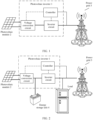
- FIG. 1 is a schematic diagram of an application scenario of a photovoltaic inverter according to an embodiment of this application.
- a power supply system includes a photovoltaic inverter 1, a power supply (namely, a photovoltaic module 2 or a photovoltaic string including a plurality of photovoltaic modules), and a power grid 3.
- the photovoltaic inverter 1 includes a voltage conversion circuit, an inverter circuit, and a controller.
- one end of the voltage conversion circuit may be configured to connect to the photovoltaic module 2, the other end of the voltage conversion circuit may be configured to connect to one end of the inverter circuit, the other end of the inverter circuit may be configured to connect to the power grid 3, and the inverter circuit and the power grid 3 are connected to a grid-connected point.
- the controller may be connected (for example, through a communication connection or an electrical connection) to the grid-connected point, the inverter circuit, and/or the voltage conversion circuit (as shown by dashed lines in the figure).
- the photovoltaic inverter 1 may convert direct current electric energy provided by the photovoltaic module 2 into alternating current electric energy, and provide the alternating current electric energy to the power grid 3.
- the photovoltaic inverter 1 may include the voltage conversion circuit and the inverter circuit.
- the voltage conversion circuit may output, to the inverter circuit, a direct current input by the photovoltaic module 2.
- the inverter circuit may receive the direct current output by the voltage conversion circuit, convert the received direct current output by the voltage conversion circuit into an alternating current, and output the alternating current to the power grid 3.
- the photovoltaic module 2 (or the photovoltaic string including the plurality of photovoltaic modules, or another direct current photovoltaic power supply) provided in this application is applicable to an application scenario of supplying power to a plurality of types of electrical devices, for example, supplying power to a base station device in a remote area without a mains supply or with a poor mains supply, or supplying power to a household device (for example, a refrigerator or an air conditioner). This may be specifically determined based on an actual application scenario, and is not limited herein.
- the power grid 3 in FIG. 1 may include an electrical device or an electric transmission device, for example, a transmission line, an electric transfer station, a communication base station, or a household device.
- a photovoltaic inverter may supply power by using a maximum power point tracking (Maximum Power Point Tracking, MPPT) technology, that is, control an output power of an inverter, to enable the photovoltaic module to work at a maximum power point, so that the inverter can output electric energy to a power grid at a maximum output power.
- MPPT Maximum Power Point Tracking
- MPPT Maximum Power Point Tracking
- the output power of the inverter also needs to be controlled to be in a non-MPPT state, that is, the inverter does not work in a maximum power state.
- the output power of the inverter may need to be increased according to a scheduling instruction.
- the maximum output power of the inverter is unknown when the inverter is in the non-MPPT state. In this case, the output power of the inverter is increased too much. As a result, the output power of the inverter exceeds a power output capability of the inverter. This may cause system breakdown.
- the controller herein may be configured to increase, based on an output power of the inverter circuit in a current time period and an output power of the inverter circuit in a first time period, an output power of the inverter circuit when the voltage conversion circuit does not work in a maximum power state.
- an increase of the output power of the inverter circuit may be referred to as an estimated power increment value of the inverter circuit, and the estimated power increment value of the inverter circuit is in direct proportion to a difference between the output power in the current time period and the output power in the first time period.
- being in direct proportion may be a linear function relationship, or may be a positive correlation relationship of a non-linear function.
- the first time period is before the current time period.
- the controller may adjust the output power of the inverter circuit in the photovoltaic inverter 1 based on the estimated power increment value.
- an output power of the photovoltaic inverter 1 is determined by the output power of the inverter circuit in the photovoltaic inverter 1, and the output power of the inverter circuit is limited by an output power of the previous-stage voltage conversion circuit.
- a power output capability of the previous-stage voltage conversion circuit needs to be considered for the increase of the output power of the inverter, and the estimated power increment value herein may be obtained based on the output power of the inverter circuit in the current time period and the output power of the inverter circuit in the first time period.
- the controller may evaluate a capability of outputting electric energy by the voltage conversion circuit in the current time period based on the output power of the inverter circuit in the current time period and the output power of the inverter circuit in the first time period, to obtain an estimated power increment value of an appropriate magnitude, and adjust the output power of the inverter based on the estimated power increment value.
- the controller may obtain an estimated power increment value of an appropriate magnitude based on an output power of the inverter circuit between the current time period and the first time period, and adjust the output power of the inverter based on the estimated power increment value.
- FIG. 2 is a schematic diagram of another application scenario of the photovoltaic inverter according to an embodiment of this application.
- the other end of the voltage conversion circuit in the photovoltaic inverter 1 may be configured to connect to an energy storage unit 4, and is configured to output, to the energy storage unit 4, a direct current input by the photovoltaic module 2.
- the inverter circuit herein may be configured to: receive the direct current output by the energy storage unit 4, convert the received direct current output by the energy storage unit 4 into an alternating current, and output the alternating current to a power grid.
- the photovoltaic inverter 1 (for example, the inverter circuit in the photovoltaic inverter 1) may further be connected to the power grid at a grid-connected point after being connected to a local load.
- the local load herein may further include a load (an electrical apparatus or an electric power transmission apparatus) connected between the grid-connected point and the inverter circuit, for example, a motor and a rectifier device.
- a photovoltaic inverter may supply power by using a maximum power point tracking (Maximum Power Point Tracking, MPPT) technology, that is, control an input power (or output power) of an inverter, to enable the photovoltaic module to work at a maximum power point, so that the inverter can output electric energy to the power grid at a maximum output power.
- MPPT Maximum Power Point Tracking
- MPPT Maximum Power Point Tracking
- the output power of the inverter also needs to be controlled to be in a non-MPPT state, that is, the inverter does not work in a maximum power state.
- the output power of the inverter may need to be increased according to a scheduling instruction.
- the maximum output power of the inverter is unknown when the inverter is in the non-MPPT state. In this case, the output power of the inverter is increased too much. As a result, the output power of the inverter exceeds a power output capability of the inverter. This may cause system breakdown.
- the power grid 3 side (or an alternating current end of the photovoltaic inverter 1) may require the inverter circuit to increase an output power (for example, an equivalent load on the power grid 3 side is increased, or a grid-connected power corresponding to a grid-connected standard on the power grid 3 side is increased, or an electric power consumption power of the local load is increased), to increase an input power of the photovoltaic inverter 1. If an output power of the photovoltaic inverter 1 is adjusted based on an excessively large adjustment step, a bus voltage may be decreased.
- the system discharges to the inverter circuit by using the energy storage unit 4, to increase an output power of the inverter circuit, or a charge power of the energy storage unit 4 is decreased. Therefore, when the photovoltaic inverter 1 or another controller in the photovoltaic system detects that the energy storage unit 4 discharges to the power grid 3 side by using the inverter circuit, or detects that the charge power of the energy storage unit 4 is decreased, or detects that the bus voltage is decreased, the photovoltaic inverter 1 or the another controller in the photovoltaic system may further adjust the inverter circuit to decrease the output power.
- This may cause the energy storage unit 4 to repeatedly switch between a charge state and a discharge state, or cause a system grid-connected power to repeatedly fluctuate, or cause the bus voltage to repeatedly fluctuate, or cause the voltage conversion circuit to fail to stably work in the maximum power state. If the output power of the inverter circuit is adjusted based on an excessively small adjustment step, the system may track the maximum power point too slowly. In this case, power supply efficiency of the photovoltaic system is reduced.
- the controller may evaluate a capability of outputting electric energy by the voltage conversion circuit in a current time period based on an output power of the inverter circuit in the current time period and an output power of the inverter circuit in a first time period, to obtain an estimated power increment value of an appropriate magnitude, and adjust the output power of the inverter based on the estimated power increment value.
- the controller may obtain an estimated power increment value of an appropriate magnitude based on an output power of the inverter circuit between the current time period and the first time period, and adjust the output power of the inverter based on the estimated power increment value.
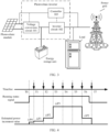
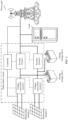
- a structure is simple, a method is simple, and applicability is high. The following uses examples to describe the photovoltaic inverter provided in this application and a working principle of the photovoltaic inverter with reference to FIG. 3 to FIG. 8 .
- FIG. 3 is a schematic diagram of a structure of a photovoltaic inverter according to an embodiment of this application.
- the photovoltaic inverter includes a voltage conversion circuit 101, an inverter circuit 102, and a controller 103.
- one end of the voltage conversion circuit 101 may be configured to connect to a photovoltaic module
- the other end of the voltage conversion circuit 101 may be configured to connect to an energy storage unit and one end of the inverter circuit 102
- the other end of the inverter circuit 102 may be configured to connect to a power grid
- the inverter circuit 102 and the power grid are connected to a grid-connected point.
- the controller 103 herein may be configured to increase, based on an output power of the inverter circuit in a current time period and an output power of the inverter circuit in a first time period, an output power of the inverter circuit when the voltage conversion circuit does not work in a maximum power state.
- an increase of the output power of the inverter circuit may be referred to as an estimated power increment value of the inverter circuit, and the estimated power increment value of the inverter circuit is in direct proportion to a difference between the output power in the current time period and the output power in the first time period.
- the first time period is before the current time period.
- FIG. 4 is a schematic diagram of a waveform of the estimated power increment value of the inverter circuit according to an embodiment of this application.
- a time axis shown in FIG. 4 is used as an example.
- the current time period may be a time period (or a moment) in which the controller 103 performs adjustment (or detection, control, or the like) on the output power of the inverter circuit this time.
- the current time period may be a time period between Tn and Tn+1 or a moment Tn+1 (where n is a natural number).
- the first time period may be a time period (or a moment) in which the controller 103 performs adjustment (or detection, control, or the like) on the output power of the inverter circuit last time (or previous time) or several times before (or several previous times).
- the first time period may be a time period between Tm and Tm+1 or a moment Tm+1 (where m is a natural number and m is less than or equal to n). It may be understood that the first time period herein may be set to any time period (or moment) before the current time period based on an application scenario, and does not necessarily need to be adjacent to the current time period.
- an output power of the inverter circuit in a time period may be an average output power (or a power value that can indicate a capability of outputting electric energy by the voltage conversion circuit, for example, a maximum/minimum output power or a weighted output power) in the time period, or may be an instantaneous output power at a specific moment (for example, a start moment, an end moment, or a sampling moment) in the time period, or may be an average output power (or a power value that can indicate a capability of outputting electric energy by the voltage conversion circuit, for example, a maximum/minimum output power or a weighted output power) at several moments (for example, a plurality of sampling moments) in the time period.
- the controller 103 may be further configured to obtain a running status signal of the voltage conversion circuit 101.
- the running status signal may indicate whether the voltage conversion circuit works in a maximum power state.
- the voltage conversion circuit 101 (or the inverter circuit 102) in the photovoltaic inverter may output the running status signal based on a current working status of the voltage conversion circuit 101.
- a control loop (or another control circuit) that takes effect (or plays a main role) in the voltage conversion circuit 101 or the inverter circuit 102 is a non-limiting power control loop
- the voltage conversion circuit 101 may output a running status signal (for example, a low-level running status signal) indicating that the voltage conversion circuit is in the maximum power state.
- a control loop (or another control circuit) that takes effect (or plays a main role) in the voltage conversion circuit 101 or the inverter circuit 102 is not a non-limiting power control loop (for example, a current or voltage control loop)
- a control loop or another control circuit that takes effect (or plays a main role) in the voltage conversion circuit 101 or the inverter circuit 102
- the voltage conversion circuit 101 may output a running status signal (for example, a high-level running status signal) indicating that the voltage conversion circuit is not in the maximum power state.
- the power grid side may require the photovoltaic inverter to increase an output power (for example, an equivalent load on the power grid side is increased, or a grid-connected power corresponding to a grid-connected standard on the power grid side is increased, or an electric power consumption power of a local load is increased), to increase an input power of the inverter circuit.
- an output power for example, an equivalent load on the power grid side is increased, or a grid-connected power corresponding to a grid-connected standard on the power grid side is increased, or an electric power consumption power of a local load is increased
- a system may discharge to the inverter circuit 102 by using the energy storage unit, to improve the output power of the inverter circuit, or a charge power of the energy storage unit may be decreased.
- the photovoltaic inverter or another controller in the photovoltaic system may further adjust the inverter circuit to decrease the output power. This may cause the energy storage unit to repeatedly switch between a charge state and a discharge state, or cause a system grid-connected power to repeatedly fluctuate, or cause the voltage conversion circuit to fail to stably work in the maximum power state. If the output power of the inverter circuit is adjusted based on an excessively small adjustment step, the system may track a maximum power point too slowly. In this case, power supply efficiency of the photovoltaic system is reduced.
- the controller 103 may obtain an estimated power increment value of an appropriate magnitude based on an output power of the inverter circuit between the current time period and the first time period, and adjust the output power of the inverter based on the estimated power increment value. This can avoid sacrificing energy storage efficiency of the energy storage unit in a process of increasing the output power of the inverter circuit by the photovoltaic system, and can also improve a speed of tracking the maximum power point by the voltage conversion circuit, improve stability of the voltage conversion circuit in a case in which the voltage conversion circuit works in the maximum power state, and improve power supply efficiency of the photovoltaic system.
- a structure is simple, a method is simple, and applicability is high.
- the controller 103 may be configured to: when the voltage conversion circuit does not work in the maximum power state, obtain the output power of the inverter circuit in the current time period (for example, a moment T1) and the output power of the inverter circuit in the first time period (for example, a moment T0).
- the current time period may be a time period (or a moment) in which the controller 103 performs adjustment (or detection, control, or the like) on the output power of the inverter circuit this time
- the first time period may be a time period (or a moment) in which the controller 103 performs adjustment (or detection, control, or the like) on the output power of the inverter circuit last time (or previous time) or several times before (or several previous times).
- the first time period herein may be set to any time period (or moment) before the current time period based on an application scenario, and does not necessarily need to be adjacent to the current time period.
- the output power of the inverter circuit in a time period may be an average output power (or a power value that can indicate a capability of outputting electric energy by the voltage conversion circuit, for example, a maximum/minimum output power or a weighted output power) in the time period, or may be an instantaneous output power at a specific moment (for example, a start moment, an end moment, or a sampling moment) in the time period, or may be an average output power (or a power value that can indicate a capability of outputting electric energy by the voltage conversion circuit, for example, a maximum/minimum output power or a weighted output power) at several moments (for example, a plurality of sampling moments) in the time period.
- the controller 103 herein may be further configured to: when the voltage conversion circuit does not work in the maximum power state, if the difference between the output power of the inverter circuit in the current time period and the output power of the inverter circuit in the first time period is less than a first threshold, set the estimated power increment value of the inverter circuit to a first power increment value ⁇ P1.
- the first threshold may be preset based on a power supply parameter of the inverter, an energy storage parameter of the energy storage unit, and/or a grid-connected parameter of the power grid in the application scenario, or may be calculated in real time based on an estimated power increment value of the inverter circuit in the first time period (or based on another parameter that can indicate the capability of outputting electric energy by the voltage conversion circuit) (for example, the first threshold may be obtained by multiplying the estimated power increment value in the first time period by a coefficient greater than 0.5 and less than 1), or may be calculated in real time based on a current environment (for example, a parameter like light intensity or a temperature).
- the first threshold herein may be a power value, may be a plurality of discrete power values, or may be a power interval including a plurality of discrete power values or continuous power values.
- the controller 103 may evaluate a capability of outputting electric energy by the voltage conversion circuit in the current time period based on a magnitude relationship between the first threshold and the difference between the output power of the inverter circuit in the current time period and the output power of the inverter circuit in the first time period, to obtain an estimated power increment value of an appropriate magnitude, and adjust the output power of the inverter based on the estimated power increment value.
- the difference between the output power in the current time period and the output power in the first time period is less than the first threshold, it is estimated that the capability of outputting electric energy by the voltage conversion circuit in the current time period is weak, so that a small estimated power increment value (for example, the first power increment value ⁇ P1) is obtained, and the output power of the inverter is adjusted based on the estimated power increment value. That is, in the current time period, if the output power of the inverter is adjusted based on an estimated power increment value greater than the first power increment value, the charge power of the energy storage unit needs to be decreased or the energy storage unit needs to discharge for compensation.
- a small estimated power increment value for example, the first power increment value ⁇ P1
- the inverter may convert a part of direct current electric energy generated by a power supply (for example, a photovoltaic module) into alternating current electric energy, and provide the alternating current electric energy for the power grid, and there is no need to decrease the charge power of the energy storage unit or discharge the energy storage unit for compensation.
- a power supply for example, a photovoltaic module
- the first power increment value may be calculated in real time based on the power supply parameter of the inverter, the energy storage parameter of the energy storage unit, and/or the grid-connected parameter of the power grid in the application scenario, or may be calculated in real time based on an estimated power increment value (or based on another parameter that can indicate the capability of outputting electric energy by the voltage conversion circuit) of the inverter circuit in a previous time period or several previous time periods (for example, the first time period), or may be calculated in real time based on the current environment (for example, the parameter like the light intensity or the temperature).
- the first power increment value herein may be a power increment value, may be a plurality of discrete power increment values, or may be a power increment interval formed including a plurality of discrete power increment values or continuous power increment values.
- energy storage efficiency of the energy storage unit can be avoided from being sacrificed in a process of increasing the output power of the inverter circuit by the photovoltaic system, stability of the voltage conversion circuit working in the maximum power state can be improved, and power supply efficiency of the photovoltaic system can be improved.
- a structure is simple, a method is simple, and applicability is high.
- the controller 103 may be further configured to: when the voltage conversion circuit does not work in the maximum power state, if the difference between the output power of the inverter circuit in the current time period (for example, a moment T2) and the output power of the inverter circuit in the first time period (for example, the moment T1) is greater than or equal to the first threshold, further increase the output power of the inverter circuit based on the output power of the inverter circuit in the current time period (for example, the moment T2) and an output power of the inverter circuit in a second time period (for example, the moment Tl or T0).
- the second time period is before the first time period.
- the current time period may be a time period (or a moment) in which the controller 103 performs adjustment (or detection, control, or the like) on the output power of the inverter circuit this time
- the second time period may be a time period (or a moment) in which the controller 103 performs adjustment (or detection, control, or the like) on the output power of the inverter circuit last time (or previous time) or several times before (or several previous times).
- the second time period herein may be set to any time period (or moment) before the current time period based on an application scenario, and does not necessarily need to be adjacent to the current time period.
- the time period (or the moment) indicated by the second time period may be the same as or different from the first time period.
- the output power of the inverter circuit in a time period may be an average output power (or a power value that can indicate a capability of receiving electric energy by the voltage conversion circuit (or outputting electric energy by the photovoltaic module), for example, a maximum/minimum output power or a weighted output power) in the time period, or may be an instantaneous output power at a specific moment (for example, a start moment, an end moment, or a sampling moment) in the time period, or may be an average output power (or a power value that can indicate a capability of receiving electric energy by the voltage conversion circuit (or outputting electric energy by the photovoltaic module), for example, a maximum/minimum output power or a weighted output power) at several moments (for example, a plurality of sampling moments) in the time period.
- an average output power or a power value that can indicate a capability of receiving electric energy by the voltage conversion circuit (or outputting electric energy by the photovoltaic module) in the time period
- the controller 103 herein may be further configured to: when the difference between the output power of the inverter circuit in the current time period (for example, the moment T2) and the output power of the inverter circuit in the first time period (for example, the moment T1) is greater than or equal to the first threshold, and a difference between the output power of the inverter circuit in the current time period (for example, the moment T2) and the output power of the inverter circuit in the second time period (for example, the moment T 1 or the moment T0) is less than a second threshold, set the estimated power increment value of the inverter circuit to a second estimated power increment value ⁇ P2.
- the second power increment value ⁇ P2 is greater than the first power increment value ⁇ P1.
- the second threshold may be preset based on the power supply parameter of the inverter, the energy storage parameter of the energy storage unit, and/or the grid-connected parameter of the power grid in the application scenario, or may be calculated in real time based on an estimated power increment value of the inverter circuit in the second time period (or based on another parameter that can indicate the capability of receiving electric energy by the voltage conversion circuit (or outputting electric energy by the photovoltaic module)) (for example, the second threshold may be obtained by multiplying the estimated power increment in the second time period by a coefficient, or the second threshold may be obtained by multiplying an estimated power increment in a previous time period of the second time period by a coefficient), or may be calculated in real time based on the current environment (for example, the parameter like the light intensity or the temperature).
- the second threshold herein may be a power value, may be a plurality of discrete power values, or may be a power interval including a plurality of discrete power values or continuous power values.
- the controller 103 may preliminarily evaluate a capability of receiving electric energy by the voltage conversion circuit in the current time period based on a magnitude relationship between the first threshold and the difference between the output power of the inverter circuit in the current time period and the output power of the inverter circuit in the first time period.
- the capability of receiving electric energy by the voltage conversion circuit (or outputting electric energy by the photovoltaic module) in the current time period is further evaluated based on a magnitude relationship between the difference between the output power of the inverter circuit in the current time period and the output power of the inverter circuit in the second time period and the second threshold, to obtain an estimated power increment value of an appropriate size, and adjust the output power of the inverter based on the estimated power increment value.
- the difference between the output power in the current time period and the output power in the first time period is greater than or equal to the first threshold, it is preliminarily estimated that the capability of outputting electric energy by the voltage conversion circuit in the current time period is strong, and the capability of receiving electric energy by the voltage conversion circuit (or outputting electric energy by the photovoltaic module) in the current time period may be further evaluated.
- the difference between the output power of the inverter circuit in the current time period and the output power of the inverter circuit in the second time period is less than the second threshold, it is further evaluated that the capability of receiving electric energy by the voltage conversion circuit (or outputting electric energy by the photovoltaic module) in the current time period is strong, to obtain an estimated power increment value (for example, the second power increment value ⁇ P2) greater than the first power increment value, and adjust the output power of the inverter based on the estimated power increment value.
- an estimated power increment value for example, the second power increment value ⁇ P2
- the output power of the inverter is adjusted based on an estimated power increment value less than the second power increment value, the capability of receiving electric energy by the voltage conversion circuit in the current time period is not fully used, and more time needs to be spent to enable the inverter to work in the maximum power state.
- the inverter in the current time period, if the output power of the inverter is adjusted based on the second power increment value, the inverter can quickly work in the maximum power state while ensuring the charge power of the energy storage unit (or ensuring that the energy storage unit does not discharge), and more efficiently convert a part of the direct current electric energy generated by the power supply (for example, the photovoltaic module) into alternating current electric energy and provide the alternating current electric energy for the power grid.
- the second power increment value is greater than the first power increment value.
- the second power increment value may be calculated in real time based on the power supply parameter of the inverter, the energy storage parameter of the energy storage unit, and/or the grid-connected parameter of the power grid in the application scenario, or may be calculated in real time based on an estimated power increment value (or based on another parameter that can indicate the capability of outputting electric energy by the voltage conversion circuit) of the inverter circuit in a previous time period or several previous time periods (for example, the first time period and the second time period), or may be calculated in real time based on the current environment (for example, the parameter like the light intensity or the temperature).
- the second power increment value herein may be a power increment value, may be a plurality of discrete power increment values, or may be a power increment interval formed including a plurality of discrete power increment values or continuous power increment values.
- energy storage efficiency of the energy storage unit can be avoided from being sacrificed in the process of increasing the output power of the inverter circuit by the photovoltaic system, a speed of tracking the maximum power point by the voltage conversion circuit can be improved, stability of the voltage conversion circuit working in the maximum power state can be improved, and power supply efficiency of the photovoltaic system can be improved.
- a structure is simple, a method is simple, and applicability is high.
- the controller 103 may be further configured to: when the voltage conversion circuit does not work in the maximum power state, if the difference between the output power of the inverter circuit in the current time period (for example, a moment T3) and the output power of the inverter circuit in the first time period (for example, the moment T2) is greater than or equal to the first threshold, and the difference between the output power of the inverter circuit in the current time period (for example, the moment T3) and the output power of the inverter circuit in the second time period (for example, the moment T2) is greater than or equal to the second threshold, set the estimated power increment value of the inverter circuit to a third power increment value ⁇ P3.
- the third power increment value ⁇ P3 is greater than the second power increment value ⁇ P2.
- the magnitude of the estimated power increment value (for example, ⁇ P1, ⁇ P2, and ⁇ P3) of the inverter circuit is in direct proportion to the difference (for example, x1, x2, and x3) between the output power in the current time period and the output power in the first time period.
- the controller 103 may preliminarily evaluate the capability of receiving electric energy by the voltage conversion circuit in the current time period based on the magnitude relationship between the first threshold and the difference between the output power of the inverter circuit in the current time period and the output power of the inverter circuit in the first time period.
- the capability of receiving electric energy by the voltage conversion circuit (or outputting electric energy by the photovoltaic module) in the current time period is further evaluated based on a magnitude relationship between the difference between the output power of the inverter circuit in the current time period and the output power of the inverter circuit in the second time period and the second threshold, to obtain an estimated power increment value of an appropriate size, and adjust the output power of the inverter based on the estimated power increment value.
- the difference between the output power in the current time period and the output power in the first time period is greater than or equal to the first threshold, it is preliminarily estimated that the capability of outputting electric energy by the voltage conversion circuit in the current time period is strong, and the capability of receiving electric energy by the voltage conversion circuit (or outputting electric energy by the photovoltaic module) in the current time period may be further evaluated.
- the difference between the output power of the inverter circuit in the current time period and the output power of the inverter circuit in the second time period is greater than or equal to the second threshold, it is further evaluated that the capability of receiving electric energy by the voltage conversion circuit (or outputting electric energy by the photovoltaic module) in the current time period is stronger, to obtain an estimated power increment value (for example, the third power increment value ⁇ P3) greater than the second power increment value, and adjust the output power of the inverter based on the estimated power increment value.
- an estimated power increment value for example, the third power increment value ⁇ P3
- the output power of the inverter is adjusted based on an estimated power increment value less than the third power increment value, the capability of receiving electric energy by the voltage conversion circuit in the current time period is not fully used, and more time needs to be spent to enable the inverter to work in the maximum power state.
- the inverter in the current time period, if the output power of the inverter is adjusted based on the third power increment value, the inverter can quickly work in the maximum power state while ensuring the charge power of the energy storage unit (or ensuring that the energy storage unit does not discharge), and more efficiently convert a part of the direct current electric energy generated by the power supply (for example, the photovoltaic module) into alternating current electric energy and provide the alternating current electric energy for the power grid.
- the third power increment value ⁇ P3 is greater than the second power increment value ⁇ P2.
- the third power increment value may be calculated in real time based on the power supply parameter of the inverter, the energy storage parameter of the energy storage unit, and/or the grid-connected parameter of the power grid in the application scenario, or may be calculated in real time based on an estimated power increment value (or based on another parameter that can indicate the capability of outputting electric energy by the voltage conversion circuit) of the inverter circuit in a previous time period or several previous time periods (for example, the first time period and the second time period), or may be calculated in real time based on the current environment (for example, the parameter like the light intensity or the temperature).
- the third power increment value herein may be a power increment value, may be a plurality of discrete power increment values, or may be a power increment interval formed including a plurality of discrete power increment values or continuous power increment values.
- energy storage efficiency of the energy storage unit can be avoided from being sacrificed in the process of increasing the output power of the inverter circuit by the photovoltaic system, a speed of tracking the maximum power point by the voltage conversion circuit can be further improved, stability of the voltage conversion circuit working in the maximum power state can be improved, and power supply efficiency of the photovoltaic system can be improved.
- a structure is simple, a method is simple, and applicability is high.
- the controller 103 may be configured to set the estimated power increment value of the inverter circuit to a fourth power increment value ⁇ P4 when the voltage conversion circuit switches from the maximum power state to a non-maximum power state (for example, at the moment T0).
- the fourth power increment value is less than the second power increment value.
- the controller 103 when the voltage conversion circuit switches from the maximum power state to the non-maximum power state, the controller 103 is at a state switching moment (or time point), and the controller 103 may first adjust the output power of the inverter based on a small estimated power increment value (for example, the fourth power increment value ⁇ P4).
- the charge power of the energy storage unit may need to be decreased or the energy storage unit may discharge for compensation.
- the output power of the inverter is adjusted based on an estimated small power increment value (for example, the fourth power increment value ⁇ P4), it can be ensured that the inverter converts a part of the direct current electric energy generated by the power supply (for example, the photovoltaic module) into alternating current electric energy and provides the alternating current electric energy for the power grid, and there is no need to decrease the charge power of the energy storage unit or discharge the energy storage unit for compensation.
- the fourth power increment value is less than the second power increment value, and may be equal to the first power increment value in some scenarios.
- the fourth power increment value may be preset based on the power supply parameter of the inverter, the energy storage parameter of the energy storage unit, and/or the grid-connected parameter of the power grid in the application scenario, or may be calculated based on the estimated power increment value of the inverter circuit (or may be calculated based on another parameter that can indicate the capability of outputting electric energy by the voltage conversion circuit) in a previous (for example, when the voltage conversion circuit is in the non-maximum power state last time) time period or several previous time periods (for example, the first time period and the second time period corresponding to a case in which the voltage conversion circuit is in the non-maximum power state last time), or may be calculated in real time based on the current environment (for example, the parameter like the light intensity or the temperature).
- the fourth power increment value herein may be a power increment value, may be a plurality of discrete power increment values, or may be a power increment interval formed including a plurality of discrete power increment values or continuous power increment values.
- the controller 103 may be configured to set the estimated power increment value of the inverter circuit to zero when the voltage conversion circuit works in the maximum power state. According to this application, stability of the voltage conversion circuit working in the maximum power state can be improved, and power supply efficiency of the photovoltaic system can be improved. A structure is simple, a method is simple, and applicability is high.
- the controller 103 may further output a power adjustment signal to the inverter circuit 102 and/or the voltage conversion circuit 101 based on the estimated power increment value, and control the output power of the inverter circuit by using the power adjustment signal.
- the controller 103 may further generate the power adjustment signal based on the estimated power increment value (for example, generate a modulation signal based on the estimated power increment value as the power adjustment signal), and control the inverter circuit 102 and/or the voltage conversion circuit 101 (for example, control the inverter circuit 102 and/or a switching transistor in the voltage conversion circuit 101) by using the power adjustment signal, to adjust the output power of the inverter circuit, so as to correspondingly adjust the input power of the inverter circuit.
- a structure is simple, and a control method is simple.
- any photovoltaic inverter shown in FIG. 1 to FIG. 4 may determine a different estimated power increment value based on a power supply capability of the photovoltaic system, and adjust the output power of the inverter based on the estimated power increment value, to improve a speed of tracking the maximum power point by the voltage conversion circuit, improve stability of the voltage conversion circuit in a case in which the voltage conversion circuit works in the maximum power state, and improve power supply efficiency of the photovoltaic system.
- a structure is simple, a method is simple, and applicability is strong.
- the photovoltaic system may include a plurality of photovoltaic inverters, where the photovoltaic inverter is any photovoltaic inverter shown in FIG. 1 to FIG. 4 .
- FIG. 5 is a schematic diagram of a structure of the photovoltaic system according to an embodiment of this application. As shown in FIG. 5 , one end of each of the plurality of photovoltaic inverters (for example, an input end of each of a voltage conversion circuit a to a voltage conversion circuit n) herein may be connected to a photovoltaic module (for example, each of a photovoltaic module a to a photovoltaic module n) in a one-to-one correspondence.
- a photovoltaic module for example, each of a photovoltaic module a to a photovoltaic module n
- the other ends (for example, output ends of an inverter circuit a to an inverter circuit n) of the plurality of photovoltaic inverters may be configured to connect to a power grid after being connected in parallel (or may be connected, by using a load, to a power grid after being connected in parallel).
- the output ends of the voltage conversion circuit a to the voltage conversion circuit n may be respectively connected to the input ends of the inverter circuit a to the inverter circuit n in a one-to-one correspondence.
- An energy storage unit a to an energy storage unit n may be respectively connected between the voltage conversion circuit a to the voltage conversion circuit n and the inverter circuit a to the inverter circuit n in a one-to-one correspondence, for example, the energy storage unit a is connected between the voltage conversion circuit a and the inverter circuit a, and the energy storage unit n is connected between the voltage conversion circuit n and the inverter circuit n.
- the plurality of photovoltaic inverters may reuse one controller (or several controllers), or controllers in the plurality of photovoltaic inverters are integrated into one control module (not shown in the figure).
- each of the controllers (or the control module) in the plurality of photovoltaic inverters may correspondingly obtain at least one appropriate estimated power increment value based on an output power of at least one inverter circuit between a current time period and a first time period, and adjust the output power of the at least one inverter circuit based on the corresponding estimated power increment value.
- energy storage efficiency of the energy storage unit can be avoided from being sacrificed in a process of increasing the output power of the inverter circuit by the photovoltaic system, a speed of tracking a maximum power point by the voltage conversion circuit can be improved, stability of the voltage conversion circuit working in a maximum power state can be improved, and power supply efficiency of the photovoltaic system can be improved.
- a structure is simple, a method is simple, and applicability is high.
- FIG. 6 is a schematic diagram of another structure of the photovoltaic system according to an embodiment of this application.
- one end of each of the plurality of photovoltaic inverters (for example, an input end of each of a voltage conversion circuit a to a voltage conversion circuit n) herein may be connected to a photovoltaic module.
- the other ends (for example, output ends of an inverter circuit a to an inverter circuit n) of the plurality of photovoltaic inverters may be configured to connect to a power grid after being connected in parallel (or may be connected, by using a load, to a power grid after being connected in parallel).
- the output ends of the voltage conversion circuit a to the voltage conversion circuit n may be respectively connected to the input ends of the inverter circuit a to the inverter circuit n in a one-to-one correspondence.
- An energy storage unit may be connected between the voltage conversion circuit a and the inverter circuit a and between the voltage conversion circuit n and the inverter circuit n.
- the plurality of photovoltaic inverters may reuse one controller (or several controllers), or controllers in the plurality of photovoltaic inverters are integrated into one control module (not shown in the figure).
- each of the controllers (or the control module) in the plurality of photovoltaic inverters may correspondingly obtain at least one appropriate estimated power increment value based on an output power of at least one inverter circuit between a current time period and a first time period, and adjust the output power of the at least one inverter circuit based on the corresponding estimated power increment value.
- energy storage efficiency of the energy storage unit can be avoided from being sacrificed in a process of increasing the output power of the inverter circuit by the photovoltaic system, a speed of tracking a maximum power point by the voltage conversion circuit can be improved, stability of the voltage conversion circuit working in a maximum power state can be improved, and power supply efficiency of the photovoltaic system can be improved.
- a structure is simple, a method is simple, and applicability is high.
- any photovoltaic inverter shown in FIG. 1 to FIG. 6 may determine a different estimated power increment value based on a power supply capability of the photovoltaic system, and adjust the output power of the inverter based on the estimated power increment value, to improve a speed of tracking the maximum power point by the voltage conversion circuit, improve stability of the voltage conversion circuit in a case in which the voltage conversion circuit works in the maximum power state, and improve power supply efficiency of the photovoltaic system.
- a structure is simple, a method is simple, and applicability is strong. For ease of description, the following uses the structure of the photovoltaic inverter shown in FIG. 1 as an example to describe a control method provided in embodiments of this application.
- FIG. 7 is a schematic flowchart of a control method according to this application.
- the control method provided in this application is applicable to a photovoltaic inverter, and the photovoltaic inverter includes a voltage conversion circuit, an inverter circuit, and a controller.
- one end of the voltage conversion circuit may be configured to connect to a photovoltaic module
- the other end of the voltage conversion circuit may be configured to connect to one end of the inverter circuit
- the other end of the inverter circuit may be configured to connect to a load and a power grid
- the inverter circuit and the power grid are connected to a grid-connected point.
- the voltage conversion circuit herein may be configured to output, to the inverter circuit, a direct current input by the photovoltaic module.
- the inverter circuit herein is configured to: receive the direct current output by the voltage conversion circuit, convert the received direct current output by the voltage conversion circuit into an alternating current, and output the alternating current to the power grid.
- the control method provided in this application includes the following steps.
- S801 Increase, based on an output power of the inverter circuit in a current time period and an output power of the inverter circuit in a first time period, an output power of the inverter circuit when the voltage conversion circuit does not work in a maximum power state.
- the output power of the inverter circuit is increased based on the output power of the inverter circuit in the current time period and the output power of the inverter circuit in the first time period.
- an increase of the output power of the inverter circuit may be represented as an estimated power increment value of the inverter circuit, and the estimated power increment value of the inverter circuit is in direct proportion to a difference between the output power in the current time period and the output power in the first time period.
- being in direct proportion may be a linear function relationship, or may be a positive correlation relationship of a non-linear function.
- the first time period is before the current time period
- the current time period may be a time period (or a moment) in which the controller performs adjustment (or detection, control, or the like) on the output power of the inverter circuit this time
- the first time period may be a time period (or a moment) in which the controller performs adjustment (or detection, control, or the like) on the output power of the inverter circuit last time (or previous time) or several times before (or several previous times).
- the first time period herein may be set to any time period (or moment) before the current time period based on an application scenario, and does not necessarily need to be adjacent to the current time period.
- an output power of the inverter circuit in a time period may be an average output power (or a power value that can indicate a capability of outputting electric energy by the voltage conversion circuit, for example, a maximum/minimum output power or a weighted output power) in the time period, or may be an instantaneous output power at a specific moment (for example, a start moment, an end moment, or a sampling moment) in the time period, or may be an average output power (or a power value that can indicate a capability of outputting electric energy by the voltage conversion circuit, for example, a maximum/minimum output power or a weighted output power) at several moments (for example, a plurality of sampling moments) in the time period.
- the photovoltaic module (or a photovoltaic string including a plurality of photovoltaic modules) may be used as a power supply to connect to the power grid by using the photovoltaic inverter, and the photovoltaic inverter may convert direct current electric energy provided by the photovoltaic module into alternating current electric energy, and provide the alternating current electric energy for the power grid.
- the photovoltaic inverter may include the voltage conversion circuit and the inverter circuit.
- the voltage conversion circuit may convert an output voltage of the photovoltaic module into a direct current voltage that matches the inverter circuit, and transmit the direct current voltage to the inverter circuit.
- the inverter circuit may convert direct current electric energy into alternating current electric energy, so that electric energy output by the inverter circuit can adapt to an alternating current power grid.
- the photovoltaic inverter may supply power by using an MPPT technology, that is, control an output power of the inverter, to enable the photovoltaic module to work at a maximum power point, so that the inverter can output electric energy to the power grid at a maximum output power.
- the output power of the inverter also needs to be controlled to be in a non-MPPT state, that is, the inverter does not work in a maximum power state.
- the output power of the inverter may need to be increased according to a scheduling instruction.
- the maximum output power of the inverter is unknown when the inverter is in the non-MPPT state. In this case, the output power of the inverter is increased too much. As a result, the output power of the inverter exceeds a power output capability of the inverter. This may cause system breakdown.
- the controller may adjust the output power of the inverter based on the estimated power increment value.
- the output power of the inverter is determined by the output power of the inverter circuit in the inverter, and the output power of the inverter circuit is limited by an output power of the previous-stage voltage conversion circuit.
- a power output capability of the previous-stage voltage conversion circuit needs to be considered for the increase of the output power of the inverter, and the estimated power increment value herein may be obtained based on the output power of the inverter circuit in the current time period and the output power of the inverter circuit in the first time period.
- the controller may evaluate a capability of outputting electric energy by the voltage conversion circuit in the current time period based on the output power of the inverter circuit in the current time period and the output power of the inverter circuit in the first time period, to obtain an estimated power increment value of an appropriate magnitude, and adjust the output power of the inverter based on the estimated power increment value.
- the controller may obtain an estimated power increment value of an appropriate magnitude based on an output power of the inverter circuit between the current time period and the first time period, and adjust the output power of the inverter based on the estimated power increment value.
- the other end of the voltage conversion circuit may be configured to connect to the energy storage unit, and is configured to output, to the energy storage unit, a direct current input by the photovoltaic module.
- the inverter circuit herein may be configured to: receive the direct current output by the energy storage unit, convert the received direct current output by the energy storage unit into an alternating current, and output the alternating current to the power grid.
- the photovoltaic inverter may further be connected to the energy storage unit (for example, connected to the energy storage unit by using the voltage conversion circuit), to store, in the energy storage unit, a part of direct current electric energy output by the photovoltaic module, convert the other part of the direct current electric energy output by the photovoltaic module into alternating current electric energy, and transmit the alternating current electric energy to the power grid.
- the photovoltaic inverter (for example, the inverter circuit in the photovoltaic inverter) may further be connected to the power grid at the grid-connected point after being connected to a local load.
- the power grid side may require the inverter circuit to increase an output power (for example, an equivalent load on the power grid side is increased, or a grid-connected power corresponding to a grid-connected standard on the power grid side is increased, or an electric power consumption power of the local load is increased), to increase an input power of the inverter circuit. If the output power of the inverter circuit is adjusted based on an excessively large adjustment step, the bus voltage may be decreased.
- the system discharges to the inverter circuit by using the energy storage unit, to increase the output power of the inverter circuit, or a charge power of the energy storage unit is decreased, or it is detected that the bus voltage is decreased.
- the photovoltaic inverter or another controller in the photovoltaic system may further adjust the inverter circuit to decrease the output power.
- This may cause the energy storage unit to repeatedly switch between a charge state and a discharge state, or cause a system grid-connected power to repeatedly fluctuate, or cause the bus voltage to repeatedly fluctuate, or cause the voltage conversion circuit to fail to stably work in the maximum power state. If the output power of the inverter circuit is adjusted based on an excessively small adjustment step, the system may track the maximum power point too slowly. In this case, power supply efficiency of the photovoltaic system is reduced.
- the controller may evaluate the capability of outputting electric energy by the voltage conversion circuit in the current time period based on the output power of the inverter circuit in the current time period and the output power of the inverter circuit in the first time period, to obtain an estimated power increment value of an appropriate magnitude, and adjust the output power of the inverter based on the estimated power increment value.
- the controller may obtain an estimated power increment value of an appropriate magnitude based on the output power of the inverter circuit between the current time period and the first time period, and adjust the output power of the inverter based on the estimated power increment value.
- This can avoid sacrificing energy storage efficiency of the energy storage unit in the process of increasing the output power of the inverter circuit by the photovoltaic system, and can also improve a speed of tracking the maximum power point by the voltage conversion circuit, improve stability of the voltage conversion circuit in a case in which the voltage conversion circuit works in the maximum power state, improve stability of the bus voltage, improve the output power of the inverter while ensuring stable running of the inverter and safe use of the power component, and improve power supply efficiency of the photovoltaic system.
- FIG. 8 is another schematic flowchart of the control method according to this application.
- the increasing, based on an output power of the inverter circuit in a current time period and an output power of the inverter circuit in a first time period, an output power of the inverter circuit when the voltage conversion circuit does not work in a maximum power state may further include the following steps.
- step S901 When the voltage conversion circuit does not work in the maximum power state, determine whether a difference between the output power of the inverter circuit in the current time period and the output power of the inverter circuit in the first time period is greater than or equal to a first threshold. If a determining result is no, step S902 is performed. If a determining result is yes, step S903 is performed.
- S902 Set the estimated power increment value of the inverter circuit to a first power increment value.
- the current time period may be a time period (or a moment) in which the controller performs adjustment (or detection, control, or the like) on the output power of the inverter circuit this time
- the first time period may be a time period (or a moment) in which the controller performs adjustment (or detection, control, or the like) on the output power of the inverter circuit last time (or previous time) or several times before (or previous several times).
- the first time period herein may be set to any time period (or moment) before the current time period based on an application scenario, and does not necessarily need to be adjacent to the current time period.
- an output power of the inverter circuit in a time period may be an average output power (or a power value that can indicate a capability of outputting electric energy by the voltage conversion circuit, for example, a maximum/minimum output power or a weighted output power) in the time period, or may be an instantaneous output power at a specific moment (for example, a start moment, an end moment, or a sampling moment) in the time period, or may be an average output power (or a power value that can indicate a capability of outputting electric energy by the voltage conversion circuit, for example, a maximum/minimum output power or a weighted output power) at several moments (for example, a plurality of sampling moments) in the time period.
- the first threshold may be preset based on a power supply parameter of the inverter, an energy storage parameter of the energy storage unit, and/or a grid-connected parameter of the power grid in the application scenario, or may be calculated in real time based on an estimated power increment value of the inverter circuit in the first time period (or based on another parameter that can indicate the capability of outputting electric energy by the voltage conversion circuit) (for example, the first threshold may be obtained by multiplying the estimated power increment value in the first time period by a coefficient greater than 0.5 and less than 1), or may be calculated in real time based on a current environment (for example, a parameter like light intensity or a temperature).
- the first threshold herein may be a power value, may be a plurality of discrete power values, or may be a power interval including a plurality of discrete power values or continuous power values.
- the controller may evaluate a capability of outputting electric energy by the voltage conversion circuit in the current time period based on a magnitude relationship between the first threshold and the difference between the output power of the inverter circuit in the current time period and the output power of the inverter circuit in the first time period, to obtain an estimated power increment value of an appropriate magnitude, and adjust the output power of the inverter based on the estimated power increment value.
- the difference between the output power in the current time period and the output power in the first time period is less than the first threshold, it is estimated that the capability of outputting electric energy by the voltage conversion circuit in the current time period is weak, so that a small estimated power increment value (for example, the first power increment value ⁇ P1) is obtained, and the output power of the inverter is adjusted based on the estimated power increment value. That is, in the current time period, if the output power of the inverter is adjusted based on an estimated power increment value greater than the first power increment value, the charge power of the energy storage unit needs to be decreased or the energy storage unit needs to discharge for compensation.
- a small estimated power increment value for example, the first power increment value ⁇ P1
- the inverter may convert a part of direct current electric energy generated by a power supply (for example, a photovoltaic module) into alternating current electric energy, and provide the alternating current electric energy for the power grid, and there is no need to decrease the charge power of the energy storage unit or discharge the energy storage unit for compensation.
- a power supply for example, a photovoltaic module
- the first power increment value may be preset based on the power supply parameter of the inverter, the energy storage parameter of the energy storage unit, and/or the grid-connected parameter of the power grid in the application scenario, or may be calculated in real time based on an estimated power increment value (or based on another parameter that can indicate the capability of outputting electric energy by the voltage conversion circuit) of the inverter circuit in a previous time period or several previous time periods (for example, the first time period) (for example, the first power increment value may be obtained by multiplying an estimated power increment in a second time period by a coefficient, or the first power increment value may be obtained by multiplying an estimated power increment in a previous time period of a second time period by a coefficient), or may be calculated in real time based on the current environment (for example, the parameter like the light intensity or the temperature).
- the first power increment value herein may be a power increment value, may be a plurality of discrete power increment values, or may be a power increment interval formed including a plurality of discrete power increment values or continuous power increment values.
- energy storage efficiency of the energy storage unit can be avoided from being sacrificed in a process of increasing the output power of the inverter circuit by the photovoltaic system, stability of the voltage conversion circuit working in the maximum power state can be improved, and power supply efficiency of the photovoltaic system can be improved.
- a structure is simple, a method is simple, and applicability is high.
- step S903 Determine whether a difference between the output power of the inverter circuit in the current time period and an output power of the inverter circuit in the second time period is greater than or equal to a second threshold. If a determining result is no, step S904 is performed. If a determining result is yes, step S905 is performed.
- S904 Set the estimated power increment value of the inverter circuit to a second power increment value.
- the current time period may be a time period (or a moment) in which the controller performs adjustment (or detection, control, or the like) on the output power of the inverter circuit this time
- the second time period may be a time period (or a moment) in which the controller performs adjustment (or detection, control, or the like) on the output power of the inverter circuit last time (or previous time) or several times before (or previous several times).
- the second time period herein may be set to any time period (or moment) before the current time period based on an application scenario, and does not necessarily need to be adjacent to the current time period.
- the time period (or the moment) indicated by the second time period may be the same as or different from the first time period.
- the output power of the inverter circuit in a time period may be an average output power (or a power value that can indicate a capability of receiving electric energy by the voltage conversion circuit (or outputting electric energy by the photovoltaic module), for example, a maximum/minimum output power or a weighted output power) in the time period, or may be an instantaneous output power at a specific moment (for example, a start moment, an end moment, or a sampling moment) in the time period, or may be an average output power (or a power value that can indicate a capability of receiving electric energy by the voltage conversion circuit (or outputting electric energy by the photovoltaic module), for example, a maximum/minimum output power or a weighted output power) at several moments (for example, a plurality of sampling moments) in the time period.
- an average output power or a power value that can indicate a capability of receiving electric energy by the voltage conversion circuit (or outputting electric energy by the photovoltaic module) in the time period
- the second threshold may be preset based on the power supply parameter of the inverter, the energy storage parameter of the energy storage unit, and/or the grid-connected parameter of the power grid in the application scenario, or may be calculated in real time based on the estimated power increment value of the inverter circuit in the second time period (or based on another parameter that can indicate the capability of receiving electric energy by the voltage conversion circuit (or outputting electric energy by the photovoltaic module)), or may be calculated in real time based on the current environment (for example, the parameter like the light intensity or the temperature).
- the second threshold herein may be a power value, may be a plurality of discrete power values, or may be a power interval including a plurality of discrete power values or continuous power values.
- the controller may preliminarily evaluate the capability of receiving electric energy by the voltage conversion circuit in the current time period based on the magnitude relationship between the first threshold and the difference between the output power of the inverter circuit in the current time period and the output power of the inverter circuit in the first time period.
- the capability of receiving electric energy by the voltage conversion circuit (or outputting electric energy by the photovoltaic module) in the current time period is further evaluated based on a magnitude relationship between the difference between the output power of the inverter circuit in the current time period and the output power of the inverter circuit in the second time period and the second threshold, to obtain an estimated power increment value of an appropriate size, and adjust the output power of the inverter based on the estimated power increment value.
- the difference between the output power in the current time period and the output power in the first time period is greater than or equal to the first threshold, it is preliminarily estimated that the capability of outputting electric energy by the voltage conversion circuit in the current time period is strong, and a capability of receiving electric energy by the voltage conversion circuit (or outputting electric energy by the photovoltaic module) in the current time period may be further evaluated.
- the difference between the output power of the inverter circuit in the current time period and the output power of the inverter circuit in the second time period is less than the second threshold, it is further evaluated that the capability of receiving electric energy by the voltage conversion circuit (or outputting electric energy by the photovoltaic module) in the current time period is strong, to obtain an estimated power increment value (for example, the second power increment value ⁇ P2) greater than the first power increment value, and adjust the output power of the inverter based on the estimated power increment value.
- an estimated power increment value for example, the second power increment value ⁇ P2
- the output power of the inverter is adjusted based on an estimated power increment value less than the second power increment value, the capability of receiving electric energy by the voltage conversion circuit in the current time period is not fully used, and more time needs to be spent to enable the inverter to work in the maximum power state.
- the inverter in the current time period, if the output power of the inverter is adjusted based on the second power increment value, the inverter can quickly work in the maximum power state while ensuring the charge power of the energy storage unit (or ensuring that the energy storage unit does not discharge), and more efficiently convert a part of the direct current electric energy generated by the power supply (for example, the photovoltaic module) into alternating current electric energy and provide the alternating current electric energy for the power grid.
- the second power increment value is greater than the first power increment value.
- the second power increment value may be calculated in real time based on the power supply parameter of the inverter, the energy storage parameter of the energy storage unit, and/or the grid-connected parameter of the power grid in the application scenario, or may be calculated in real time based on an estimated power increment value (or based on another parameter that can indicate the capability of outputting electric energy by the voltage conversion circuit) of the inverter circuit in a previous time period or several previous time periods (for example, the first time period and the second time period), or may be calculated in real time based on the current environment (for example, the parameter like the light intensity or the temperature).
- the second power increment value herein may be a power increment value, may be a plurality of discrete power increment values, or may be a power increment interval formed including a plurality of discrete power increment values or continuous power increment values.
- energy storage efficiency of the energy storage unit can be avoided from being sacrificed in the process of increasing the output power of the inverter circuit by the photovoltaic system, a speed of tracking the maximum power point by the voltage conversion circuit can be improved, stability of the voltage conversion circuit working in the maximum power state can be improved, and power supply efficiency of the photovoltaic system can be improved.
- a structure is simple, a method is simple, and applicability is high.
- S905 Set the estimated power increment value of the inverter circuit to a third power increment value.
- the controller may preliminarily evaluate the capability of receiving electric energy by the voltage conversion circuit in the current time period based on the magnitude relationship between the first threshold and the difference between the output power of the inverter circuit in the current time period and the output power of the inverter circuit in the first time period.
- the capability of receiving electric energy by the voltage conversion circuit (or outputting electric energy by the photovoltaic module) in the current time period is further evaluated based on a magnitude relationship between the difference between the output power of the inverter circuit in the current time period and the output power of the inverter circuit in the second time period and the second threshold, to obtain an estimated power increment value of an appropriate size, and adjust the output power of the inverter based on the estimated power increment value.
- the difference between the output power in the current time period and the output power in the first time period is greater than or equal to the first threshold, it is preliminarily estimated that the capability of outputting electric energy by the voltage conversion circuit in the current time period is strong, and a capability of receiving electric energy by the voltage conversion circuit (or outputting electric energy by the photovoltaic module) in the current time period may be further evaluated.
- the difference between the output power of the inverter circuit in the current time period and the output power of the inverter circuit in the second time period is greater than or equal to the second threshold, it is further evaluated that the capability of receiving electric energy by the voltage conversion circuit (or outputting electric energy by the photovoltaic module) in the current time period is stronger, to obtain an estimated power increment value (for example, the third power increment value ⁇ P3) greater than the second power increment value, and adjust the output power of the inverter based on the estimated power increment value.
- an estimated power increment value for example, the third power increment value ⁇ P3
- the output power of the inverter is adjusted based on an estimated power increment value less than the third power increment value, the capability of receiving electric energy by the voltage conversion circuit in the current time period is not fully used, and more time needs to be spent to enable the inverter to work in the maximum power state.
- the inverter in the current time period, if the output power of the inverter is adjusted based on the third power increment value, the inverter can quickly work in the maximum power state while ensuring the charge power of the energy storage unit (or ensuring that the energy storage unit does not discharge), and more efficiently convert a part of the direct current electric energy generated by the power supply (for example, the photovoltaic module) into alternating current electric energy and provide the alternating current electric energy for the power grid.
- the third power increment value is greater than the second power increment value.
- the third power increment value may be calculated in real time based on the power supply parameter of the inverter, the energy storage parameter of the energy storage unit, and/or the grid-connected parameter of the power grid in the application scenario, or may be calculated in real time based on an estimated power increment value (or based on another parameter that can indicate the capability of outputting electric energy by the voltage conversion circuit) of the inverter circuit in a previous time period or several previous time periods (for example, the first time period and the second time period), or may be calculated in real time based on the current environment (for example, the parameter like the light intensity or the temperature).
- the third power increment value herein may be a power increment value, may be a plurality of discrete power increment values, or may be a power increment interval formed including a plurality of discrete power increment values or continuous power increment values.
- energy storage efficiency of the energy storage unit can be avoided from being sacrificed in the process of increasing the output power of the inverter circuit by the photovoltaic system, a speed of tracking the maximum power point by the voltage conversion circuit can be further improved, stability of the voltage conversion circuit working in the maximum power state can be improved, and power supply efficiency of the photovoltaic system can be improved.
- a structure is simple, a method is simple, and applicability is high.
- the method further includes: setting the estimated power increment value of the inverter circuit to a fourth power increment value when the voltage conversion circuit switches from the maximum power state to a non-maximum power state, where the fourth power increment value is less than the second power increment value.
- the controller when the voltage conversion circuit switches from the maximum power state to the non-maximum power state, the controller is at a state switching moment (or time point), and the controller may first adjust the output power of the inverter based on a small estimated power increment value (for example, the fourth power increment value ⁇ P4). That is, when the voltage conversion circuit switches from the maximum power state to the non-maximum power state, if the output power of the inverter is adjusted based on an estimated power increment value greater than the fourth power increment value, the charge power of the energy storage unit may need to be decreased or the energy storage unit may discharge for compensation.
- a small estimated power increment value for example, the fourth power increment value ⁇ P4
- the output power of the inverter when the voltage conversion circuit switches from the maximum power state to the non-maximum power state, if the output power of the inverter is adjusted based on an estimated small power increment value (for example, the fourth power increment value), it can be ensured that the inverter converts a part of the direct current electric energy generated by the power supply (for example, the photovoltaic module) into alternating current electric energy and provides the alternating current electric energy for the power grid, and there is no need to decrease the charge power of the energy storage unit or discharge the energy storage unit for compensation.
- the fourth power increment value is less than the second power increment value, and may be equal to the first power increment value in some scenarios.
- the fourth power increment value may be preset based on the power supply parameter of the inverter, the energy storage parameter of the energy storage unit, and/or the grid-connected parameter of the power grid in the application scenario, or may be calculated based on the estimated power increment value of the inverter circuit (or may be calculated based on another parameter that can indicate the capability of outputting electric energy by the voltage conversion circuit) in a previous (for example, when the voltage conversion circuit is in the non-maximum power state last time) time period or several previous time periods (for example, the first time period and the second time period corresponding to a case in which the voltage conversion circuit is in the non-maximum power state last time), or may be calculated in real time based on the current environment (for example, the parameter like the light intensity or the temperature).
- the fourth power increment value herein may be a power increment value, may be a plurality of discrete power increment values, or may be a power increment interval formed including a plurality of discrete power increment values or continuous power increment values.
- the method further includes: setting the estimated power increment value of the inverter circuit to zero when the voltage conversion circuit works in the maximum power state. According to this application, stability of the voltage conversion circuit working in the maximum power state can be improved, and power supply efficiency of the photovoltaic system can be improved. A structure is simple, a method is simple, and applicability is high.
- the method further includes: outputting a power adjustment signal the voltage conversion circuit based on the estimated power increment value, and controlling the output power of the inverter circuit by using the power adjustment signal.
- the controller may further generate the power adjustment signal based on the estimated power increment value (for example, generate a modulation signal based on the estimated power increment value as the power adjustment signal), and control the inverter circuit and/or the voltage conversion circuit (for example, control the inverter circuit and/or a switching transistor in the voltage conversion circuit) by using the power adjustment signal, to adjust the output power of the inverter circuit, so as to correspondingly adjust the input power of the inverter circuit.
- a structure is simple, and a control method is simple.
- the photovoltaic inverter may determine a different estimated power increment value based on a power supply capability of the photovoltaic system, and adjust the output power of the inverter based on the estimated power increment value, to improve a speed of tracking the maximum power point by the voltage conversion circuit, improve stability of the voltage conversion circuit in a case in which the voltage conversion circuit works in the maximum power state, and improve power supply efficiency of the photovoltaic system.
- a structure is simple, a method is simple, and applicability is strong.
Landscapes
- Engineering & Computer Science (AREA)
- Power Engineering (AREA)
- Inverter Devices (AREA)
- Supply And Distribution Of Alternating Current (AREA)
- Charge And Discharge Circuits For Batteries Or The Like (AREA)
Abstract
This application provides a photovoltaic inverter and a control method thereof, and a photovoltaic system. The photovoltaic inverter system includes a voltage conversion circuit, an inverter circuit, and a controller. The controller is configured to increase, based on an output power of the inverter circuit in a current time period and an output power of the inverter circuit in a first time period, an output power of the inverter circuit when the voltage conversion circuit does not work in a maximum power state. An increase of the output power of the inverter circuit is an estimated power increment value of the inverter circuit. According to this application, the inverter can avoid a decrease of a bus voltage that is caused in a process of increasing the output power of the inverter circuit by the photovoltaic system based on an excessively large step, improve stability of the bus voltage, stably increase an output power of the inverter while ensuring stable operation of the inverter and safe use of a power component, and improve power supply efficiency of the photovoltaic system.
Description
- This application relates to the field of power electronics technologies, and in particular, to a photovoltaic inverter and a control method thereof, and a photovoltaic system.
- In the field of power electronics technologies, an inverter circuit in a photovoltaic inverter is usually used to convert direct current electric energy into alternating current electric energy, so that the electric energy is transmitted between a power supply (for example, a photovoltaic module) and a load. In such a photovoltaic system, the photovoltaic inverter usually needs to adjust a supply power (for example, an output power) based on a power supply capability of the photovoltaic module, so that a voltage conversion circuit works at a maximum power point. This process is referred to as maximum power point tracking (Maximum Power Point Tracking, MPPT). Generally, in actual application, the photovoltaic inverter may be further connected to an energy storage unit. The photovoltaic inverter herein may convert a part of direct current electric energy output by the photovoltaic module into alternating current electric energy, provide the alternating current electric energy for the load or a power grid to use, and store, in the energy storage unit, the other part of direct current electric energy output by the photovoltaic module. In a research and practice process, the conventional technology has the following disadvantages: when the photovoltaic inverter charges the energy storage unit at a full power or when the energy storage unit is in a full-charged state, if the photovoltaic inverter needs to increase an output power of the inverter circuit in a maximum power point tracking process, a charge power of the energy storage unit may be decreased or the energy storage unit may change from charging to discharging. As a result, the inverter or a control module of the inverter detects that the energy storage unit is charged at a lower power or the energy storage unit is in a discharge state, and decreases an output power of the inverter. This control method may cause the energy storage unit to repeatedly switch between a charge state and the discharge state, or cause a system grid-connected power to repeatedly fluctuate, and consequently, the inverter cannot stably work at a maximum power point. This increases power supply costs, and has poor adaptability.
- This application provides a photovoltaic inverter and a control method thereof, and a photovoltaic system, to prevent a decrease of a bus voltage in a process of increasing an output power of an inverter circuit by the photovoltaic system based on an excessively large step, improve stability of the bus voltage, stably increase an output power of the inverter while ensuring stable operation of the inverter and safe use of a power component, and improve power supply efficiency of the photovoltaic system.
- According to a first aspect, this application provides a photovoltaic inverter. The photovoltaic inverter includes a voltage conversion circuit, an inverter circuit, and a controller. Herein, one end of the voltage conversion circuit may be configured to connect to a photovoltaic module, the other end of the voltage conversion circuit may be configured to connect to one end of the inverter circuit, the other end of the inverter circuit may be configured to connect to a power grid, and the inverter circuit and the power grid are connected to a grid-connected point. The voltage conversion circuit herein may be configured to output, to the inverter circuit, a direct current input by the photovoltaic module. The inverter circuit herein is configured to: receive the direct current output by the voltage conversion circuit, convert the received direct current output by the voltage conversion circuit into an alternating current, and output the alternating current to the power grid. The controller herein may be configured to increase, based on an output power of the inverter circuit in a current time period and an output power of the inverter circuit in a first time period, an output power of the inverter circuit when the voltage conversion circuit does not work in a maximum power state. Herein, an increase of the output power of the inverter circuit may be referred to as an estimated power increment value of the inverter circuit, and the estimated power increment value of the inverter circuit is in direct proportion to a difference between the output power in the current time period and the output power in the first time period. Herein, being in direct proportion may be a linear function relationship, or may be a positive correlation relationship of a non-linear function. For example, if the difference between the output power of the inverter circuit in the current time period and the output power of the inverter circuit in the first time period is x, the estimated power increment value ΔP of the inverter circuit may be calculated according to a formula △P=k×x+A, where k and A are coefficients or parameters designed based on a specific application scenario. The first time period is before the current time period.
- In this application, the photovoltaic module (or a photovoltaic string including a plurality of photovoltaic modules) may be used as a power supply to connect to the power grid by using the photovoltaic inverter, and the photovoltaic inverter may convert direct current electric energy provided by the photovoltaic module into alternating current electric energy, and provide the alternating current electric energy for the power grid. Herein, the photovoltaic inverter may include the voltage conversion circuit and the inverter circuit. The voltage conversion circuit may convert an output voltage of the photovoltaic module into a direct current voltage that matches the inverter circuit, and transmit the direct current voltage to the inverter circuit. The inverter circuit may convert direct current electric energy into alternating current electric energy, so that electric energy output by the inverter circuit can adapt to an alternating current power grid.
- In a photovoltaic power supply scenario, to maximize use of electric energy generated by the photovoltaic module, the photovoltaic inverter may supply power by using a maximum power point tracking (Maximum Power Point Tracking, MPPT) technology, that is, control an output power of the inverter, to enable the photovoltaic module to work at a maximum power point, so that the inverter can output electric energy to the power grid at a maximum output power. However, in some cases, for example, if an output power required by the power grid (including a load) is low, the output power of the inverter also needs to be controlled to be in a non-MPPT state, that is, the inverter does not work in a maximum power state. In the non-MPPT state, the output power of the inverter may need to be increased according to a scheduling instruction. However, the maximum output power of the inverter is unknown when the inverter is in the non-MPPT state. In this case, the output power of the inverter is increased too much. As a result, the output power of the inverter exceeds a power output capability of the inverter. This may cause system breakdown.
- In this application, a concept of the estimated power increment value is introduced. The controller may adjust the output power of the inverter based on the estimated power increment value. It should be understood that the output power of the inverter is determined by the output power of the inverter circuit in the inverter, and the output power of the inverter circuit is limited by an output power of the previous-stage voltage conversion circuit. In other words, a power output capability of the previous-stage voltage conversion circuit needs to be considered for the increase of the output power of the inverter, and the estimated power increment value herein may be obtained based on the output power of the inverter circuit in the current time period and the output power of the inverter circuit in the first time period. It may be understood that the controller may evaluate a capability of outputting electric energy by the voltage conversion circuit in the current time period based on the output power of the inverter circuit in the current time period and the output power of the inverter circuit in the first time period, to obtain an estimated power increment value of an appropriate magnitude, and adjust the output power of the inverter based on the estimated power increment value. In other words, the controller may obtain an estimated power increment value of an appropriate magnitude based on an output power of the inverter circuit between the current time period and the first time period, and adjust the output power of the inverter based on the estimated power increment value. This can avoid a decrease of a bus voltage that is caused in a process of increasing the output power of the inverter circuit by the photovoltaic system based on an excessively large step, improve stability of the bus voltage, stably increase the output power of the inverter while ensuring stable operation of the inverter and safe use of a power component, and improve power supply efficiency of the photovoltaic system.
- With reference to the first aspect, in a first possible implementation, the other end of the voltage conversion circuit may be configured to connect to an energy storage unit, and is configured to output, to the energy storage unit, a direct current input by the photovoltaic module. The inverter circuit herein may be configured to: receive the direct current output by the energy storage unit, convert the received direct current output by the energy storage unit into an alternating current, and output the alternating current to the power grid.
- It may be understood that, when the photovoltaic inverter does not work in the maximum power state, the power grid side (or an alternating current end of the photovoltaic inverter) may require the photovoltaic inverter to increase an output power (for example, an equivalent load on the power grid side is increased, or a grid-connected power corresponding to a grid-connected standard on the power grid side is increased, or an electric power consumption power of a local load is increased), to increase the input power of the inverter circuit. If the output power of the inverter circuit is adjusted based on the excessively large adjustment step, the bus voltage may be decreased. As a result, the system discharges to the inverter circuit by using the energy storage unit, to increase the output power of the inverter circuit, or a charge power of the energy storage unit is decreased. Therefore, when the photovoltaic inverter or another controller in the photovoltaic system detects that the energy storage unit discharges to the inverter circuit by using the inverter circuit, or detects that the charge power of the energy storage unit is decreased, or detects that the bus voltage is decreased, the photovoltaic inverter or the another controller in the photovoltaic system may further adjust the inverter circuit to decrease the output power. This may cause the energy storage unit to repeatedly switch between a charge state and a discharge state, or cause a system grid-connected power to repeatedly fluctuate, or cause the bus voltage to repeatedly fluctuate, or cause the voltage conversion circuit to fail to stably work in the maximum power state. If the output power of the inverter circuit is adjusted based on an excessively small adjustment step, the system may track the maximum power point too slowly. In this case, power supply efficiency of the photovoltaic system is reduced.
- In this application, the controller may evaluate the capability of outputting electric energy by the voltage conversion circuit in the current time period based on the output power of the inverter circuit in the current time period and the output power of the inverter circuit in the first time period, to obtain an estimated power increment value of an appropriate magnitude, and adjust the output power of the inverter based on the estimated power increment value. In other words, the controller may obtain an estimated power increment value of an appropriate magnitude based on an output power of the inverter circuit between the current time period and the first time period, and adjust the output power of the inverter based on the estimated power increment value. This can avoid sacrificing energy storage efficiency of the energy storage unit in a process of increasing the output power of the inverter circuit by the photovoltaic system, and can also improve a speed of tracking the maximum power point by the voltage conversion circuit, improve stability of the voltage conversion circuit in a case in which the voltage conversion circuit works in a maximum power state, improve stability of the bus voltage, and improve the output power of the inverter while ensuring stable running of the inverter and safe use of a power component, and improve power supply efficiency of the photovoltaic system. A structure is simple, a method is simple, and applicability is high.
- With reference to the first aspect or the first possible implementation of the first aspect, in a second possible implementation, the controller may be configured to: when the voltage conversion circuit does not work in the maximum power state, if the difference between the output power of the inverter circuit in the current time period and the output power of the inverter circuit in the first time period is less than a first threshold, set the estimated power increment value of the inverter circuit to a first power increment value.
- In this application, the controller may evaluate a capability of outputting electric energy by the voltage conversion circuit in the current time period based on a magnitude relationship between the first threshold and the difference between the output power of the inverter circuit in the current time period and the output power of the inverter circuit in the first time period, to obtain an estimated power increment value of an appropriate magnitude, and adjust the output power of the inverter based on the estimated power increment value. For example, when the difference between the output power in the current time period and the output power in the first time period is less than the first threshold, it is estimated that the capability of outputting electric energy by the voltage conversion circuit in the current time period is weak, so that a small estimated power increment value (for example, the first power increment value) is obtained, and the output power of the inverter is adjusted based on the estimated power increment value. That is, in the current time period, if the output power of the inverter is adjusted based on an estimated power increment value greater than the first power increment value, the charge power of the energy storage unit needs to be decreased or the energy storage unit needs to discharge for compensation. In other words, in the current time period, if the output power of the inverter is adjusted based on the first power increment value, the inverter may convert a part of direct current electric energy generated by a power supply (for example, a photovoltaic module) into alternating current electric energy, and provide the alternating current electric energy for the power grid, and there is no need to decrease the charge power of the energy storage unit or discharge the energy storage unit for compensation. Herein, the first power increment value may be calculated in real time based on the power supply parameter of the inverter, the energy storage parameter of the energy storage unit, and/or the grid-connected parameter of the power grid in the application scenario, or may be calculated in real time based on an estimated power increment value (or based on another parameter that can indicate the capability of outputting electric energy by the voltage conversion circuit) of the inverter circuit in a previous time period or several previous time periods (for example, the first time period), or may be calculated in real time based on the current environment (for example, the parameter like the light intensity or the temperature). The first power increment value herein may be a power increment value, may be a plurality of discrete power increment values, or may be a power increment interval formed including a plurality of discrete power increment values or continuous power increment values. According to this application, energy storage efficiency of the energy storage unit can be avoided from being sacrificed in a process of increasing the output power of the inverter circuit by the photovoltaic system, stability of the voltage conversion circuit working in the maximum power state can be improved, and power supply efficiency of the photovoltaic system can be improved. A structure is simple, a method is simple, and applicability is high.
- With reference to the second possible implementation of the first aspect, in a third possible implementation, the controller may be further configured to: when the voltage conversion circuit does not work in the maximum power state, if the difference between the output power of the inverter circuit in the current time period and the output power of the inverter circuit in the first time period is greater than or equal to the first threshold, and a difference between the output power of the inverter circuit in the current time period and an output power of the inverter circuit in a second time period is less than a second threshold, set the estimated power increment value of the inverter circuit to a second power increment value, where the second time period is before the first time period, and the second power increment value is greater than the first power increment value.
- In this application, the controller may preliminarily evaluate the capability of receiving electric energy by the voltage conversion circuit in the current time period based on the magnitude relationship between the first threshold and the difference between the output power of the inverter circuit in the current time period and the output power of the inverter circuit in the first time period. When the difference between the output power in the current time period and the output power in the first time period is greater than or equal to the first threshold, the capability of receiving electric energy by the voltage conversion circuit (or outputting electric energy by the photovoltaic module) in the current time period is further evaluated based on a magnitude relationship between the difference between the output power of the inverter circuit in the current time period and the output power of the inverter circuit in the second time period and the second threshold, to obtain an estimated power increment value of an appropriate size, and adjust the output power of the inverter based on the estimated power increment value. For example, when the difference between the output power in the current time period and the output power in the first time period is greater than or equal to the first threshold, it is preliminarily estimated that the capability of outputting electric energy by the voltage conversion circuit in the current time period is strong, and a capability of receiving electric energy by the voltage conversion circuit (or outputting electric energy by the photovoltaic module) in the current time period may be further evaluated. When the difference between the output power of the inverter circuit in the current time period and the output power of the inverter circuit in the second time period is less than the second threshold, it is further evaluated that the capability of receiving electric energy by the voltage conversion circuit (or outputting electric energy by the photovoltaic module) in the current time period is strong, to obtain an estimated power increment value (for example, the second power increment value) greater than the first power increment value, and adjust the output power of the inverter based on the estimated power increment value.
- That is, in the current time period, if the output power of the inverter is adjusted based on an estimated power increment value less than the second power increment value, the capability of receiving electric energy by the voltage conversion circuit in the current time period is not fully used, and more time needs to be spent to enable the inverter to work in the maximum power state. In other words, in the current time period, if the output power of the inverter is adjusted based on the second power increment value, the inverter can quickly work in the maximum power state while ensuring the charge power of the energy storage unit (or ensuring that the energy storage unit does not discharge), and more efficiently convert a part of the direct current electric energy generated by the power supply (for example, the photovoltaic module) into alternating current electric energy and provide the alternating current electric energy for the power grid. Herein, the second power increment value is greater than the first power increment value. The second power increment value may be calculated in real time based on the power supply parameter of the inverter, the energy storage parameter of the energy storage unit, and/or the grid-connected parameter of the power grid in the application scenario, or may be calculated in real time based on an estimated power increment value (or based on another parameter that can indicate the capability of outputting electric energy by the voltage conversion circuit) of the inverter circuit in a previous time period or several previous time periods (for example, the first time period and the second time period), or may be calculated in real time based on the current environment (for example, the parameter like the light intensity or the temperature). The second power increment value herein may be a power increment value, may be a plurality of discrete power increment values, or may be a power increment interval formed including a plurality of discrete power increment values or continuous power increment values. According to this application, energy storage efficiency of the energy storage unit can be avoided from being sacrificed in the process of increasing the output power of the inverter circuit by the photovoltaic system, a speed of tracking the maximum power point by the voltage conversion circuit can be improved, stability of the voltage conversion circuit working in the maximum power state can be improved, and power supply efficiency of the photovoltaic system can be improved. A structure is simple, a method is simple, and applicability is high.
- With reference to the third possible implementation of the first aspect, in a fourth possible implementation, the controller may be further configured to: when the voltage conversion circuit does not work in the maximum power state, if the difference between the output power of the inverter circuit in the current time period and the output power of the inverter circuit in the first time period is greater than or equal to the first threshold, and the difference between the output power of the inverter circuit in the current time period and the output power of the inverter circuit in the second time period is greater than or equal to the second threshold, set the estimated power increment value of the inverter circuit to a third power increment value, where the third power increment value is greater than the second power increment value.
- In this application, the controller may preliminarily evaluate the capability of receiving electric energy by the voltage conversion circuit in the current time period based on the magnitude relationship between the first threshold and the difference between the output power of the inverter circuit in the current time period and the output power of the inverter circuit in the first time period. When the difference between the output power in the current time period and the output power in the first time period is greater than or equal to the first threshold, the capability of receiving electric energy by the voltage conversion circuit (or outputting electric energy by the photovoltaic module) in the current time period is further evaluated based on a magnitude relationship between the difference between the output power of the inverter circuit in the current time period and the output power of the inverter circuit in the second time period and the second threshold, to obtain an estimated power increment value of an appropriate size, and adjust the output power of the inverter based on the estimated power increment value. For example, when the difference between the output power in the current time period and the output power in the first time period is greater than or equal to the first threshold, it is preliminarily estimated that the capability of outputting electric energy by the voltage conversion circuit in the current time period is strong, and a capability of receiving electric energy by the voltage conversion circuit (or outputting electric energy by the photovoltaic module) in the current time period may be further evaluated. When the difference between the output power of the inverter circuit in the current time period and the output power of the inverter circuit in the second time period is greater than or equal to the second threshold, it is further evaluated that the capability of receiving electric energy by the voltage conversion circuit (or outputting electric energy by the photovoltaic module) in the current time period is stronger, to obtain an estimated power increment value (for example, the third power increment value) greater than the second power increment value, and adjust the output power of the inverter based on the estimated power increment value.
- That is, in the current time period, if the output power of the inverter is adjusted based on an estimated power increment value less than the third power increment value, the capability of receiving electric energy by the voltage conversion circuit in the current time period is not fully used, and more time needs to be spent to enable the inverter to work in the maximum power state. In other words, in the current time period, if the output power of the inverter is adjusted based on the third power increment value, the inverter can quickly work in the maximum power state while ensuring the charge power of the energy storage unit (or ensuring that the energy storage unit does not discharge), and more efficiently convert a part of the direct current electric energy generated by the power supply (for example, the photovoltaic module) into alternating current electric energy and provide the alternating current electric energy for the power grid. Herein, the third power increment value is greater than the second power increment value. The third power increment value may be calculated in real time based on the power supply parameter of the inverter, the energy storage parameter of the energy storage unit, and/or the grid-connected parameter of the power grid in the application scenario, or may be calculated in real time based on an estimated power increment value (or based on another parameter that can indicate the capability of outputting electric energy by the voltage conversion circuit) of the inverter circuit in a previous time period or several previous time periods (for example, the first time period and the second time period), or may be calculated in real time based on the current environment (for example, the parameter like the light intensity or the temperature). The third power increment value herein may be a power increment value, may be a plurality of discrete power increment values, or may be a power increment interval formed including a plurality of discrete power increment values or continuous power increment values. According to this application, energy storage efficiency of the energy storage unit can be avoided from being sacrificed in the process of increasing the output power of the inverter circuit by the photovoltaic system, a speed of tracking the maximum power point by the voltage conversion circuit can be further improved, stability of the voltage conversion circuit working in the maximum power state can be improved, and power supply efficiency of the photovoltaic system can be improved. A structure is simple, a method is simple, and applicability is high.
- With reference to the third or the fourth possible implementation of the first aspect, in a fifth possible implementation, the controller may be configured to set the estimated power increment value of the inverter circuit to a fourth power increment value when the voltage conversion circuit switches from the maximum power state to a non-maximum power state. The fourth power increment value is less than the second power increment value. Herein, when the voltage conversion circuit switches from the maximum power state to the non-maximum power state, the controller is at a state switching moment (or time point), and the controller may first adjust the output power of the inverter based on a small estimated power increment value (for example, the fourth power increment value). That is, when the voltage conversion circuit switches from the maximum power state to the non-maximum power state, if the output power of the inverter is adjusted based on an estimated power increment value greater than the fourth power increment value, the charge power of the energy storage unit may need to be decreased or the energy storage unit may discharge for compensation. In other words, when the voltage conversion circuit switches from the maximum power state to the non-maximum power state, if the output power of the inverter is adjusted based on an estimated small power increment value (for example, the fourth power increment value), it can be ensured that the inverter converts a part of the direct current electric energy generated by the power supply (for example, the photovoltaic module) into alternating current electric energy and provides the alternating current electric energy for the power grid, and there is no need to decrease the charge power of the energy storage unit or discharge the energy storage unit for compensation. Herein, the fourth power increment value is less than the second power increment value, and may be equal to the first power increment value in some scenarios. The fourth power increment value may be preset based on the power supply parameter of the inverter, the energy storage parameter of the energy storage unit, and/or the grid-connected parameter of the power grid in the application scenario, or may be calculated based on the estimated power increment value of the inverter circuit (or may be calculated based on another parameter that can indicate the capability of outputting electric energy by the voltage conversion circuit) in a previous (for example, when the voltage conversion circuit is in the non-maximum power state last time) time period or several previous time periods (for example, the first time period and the second time period corresponding to a case in which the voltage conversion circuit is in the non-maximum power state last time), or may be calculated in real time based on the current environment (for example, the parameter like the light intensity or the temperature). The fourth power increment value herein may be a power increment value, may be a plurality of discrete power increment values, or may be a power increment interval formed including a plurality of discrete power increment values or continuous power increment values. According to this application, a case in which the photovoltaic system sacrifices energy storage efficiency of the energy storage unit when the voltage conversion circuit switches from the maximum power state to the non-maximum power state can be avoided, stability of the voltage conversion circuit working in the maximum power state can be improved, and power supply efficiency of the photovoltaic system can be improved. A structure is simple, a method is simple, and applicability is high.
- With reference to any one of the first aspect or the possible implementations of the first aspect, in a sixth possible implementation, the controller may be further configured to obtain a running status signal of the voltage conversion circuit. The running status signal may indicate whether the voltage conversion circuit works in a maximum power state. Herein, the voltage conversion circuit (or the inverter circuit) in the photovoltaic inverter may output the running status signal based on a current working status of the voltage conversion circuit. For example, when a control loop (or another control circuit) that takes effect (or plays a main role) in the voltage conversion circuit or the inverter circuit is a non-limiting power control loop, it may be determined that the voltage conversion circuit currently works in the maximum power state, and the photovoltaic inverter may output a running status signal indicating that the voltage conversion circuit is in the maximum power state.
- With reference to any one of the first aspect or the possible implementations of the first aspect, in a seventh possible implementation, the controller may be configured to set the estimated power increment value of the inverter circuit to zero when the voltage conversion circuit works in the maximum power state. According to this application, stability of the voltage conversion circuit working in the maximum power state can be improved, and power supply efficiency of the photovoltaic system can be improved. A structure is simple, a method is simple, and applicability is high.
- With reference to any one of the first aspect or the possible implementations of the first aspect, in an eighth possible implementation, the controller may further output a power adjustment signal to the inverter circuit and/or the voltage conversion circuit based on the estimated power increment value, and control the output power of the inverter circuit by using the power adjustment signal. Herein, the controller may further generate the power adjustment signal based on the estimated power increment value (for example, generate a modulation signal based on the estimated power increment value as the power adjustment signal), and control the inverter circuit and/or the voltage conversion circuit (for example, control the inverter circuit and/or a switching transistor in the voltage conversion circuit) by using the power adjustment signal, to adjust the output power of the inverter circuit, so as to correspondingly adjust the input power of the inverter circuit. A structure is simple, and a control method is simple.
- According to a second aspect, this application provides a photovoltaic system. The photovoltaic system may include a plurality of photovoltaic inverters according to any one of the first aspect or the possible implementations of the first aspect. One end of each of the plurality of photovoltaic inverters herein may be configured to connect to a photovoltaic module. The other ends of the plurality of photovoltaic inverters may be configured to connect to a power grid after being connected in parallel. The plurality of photovoltaic inverters reuses one controller or several controllers, or controllers in the plurality of photovoltaic inverters are integrated into one control module. According to this application, each of the controllers (or the control module) in the plurality of photovoltaic inverters may correspondingly obtain at least one appropriate estimated power increment value based on an output power of at least one inverter circuit between a current time period and a first time period, and adjust the output power of the at least one inverter circuit based on the corresponding estimated power increment value. In this way, energy storage efficiency of an energy storage unit can be avoided from being sacrificed in a process of increasing the output power of the inverter circuit by the photovoltaic system, a speed of tracking a maximum power point by a voltage conversion circuit can be improved, stability of the voltage conversion circuit working in a maximum power state can be improved, and power supply efficiency of the photovoltaic system can be improved. A structure is simple, a method is simple, and applicability is high.
- According to a third aspect, this application provides a control method of a photovoltaic inverter. The control method is applicable to a photovoltaic inverter, and the photovoltaic inverter includes a voltage conversion circuit, an inverter circuit, and a controller. Herein, one end of the voltage conversion circuit may be configured to connect to a photovoltaic module, the other end of the voltage conversion circuit may be configured to connect to one end of the inverter circuit, the other end of the inverter circuit may be configured to connect to a load and a power grid, and the inverter circuit and the power grid are connected to a grid-connected point. The voltage conversion circuit herein may be configured to output, to the inverter circuit, a direct current input by the photovoltaic module. The inverter circuit herein is configured to: receive the direct current output by the voltage conversion circuit, convert the received direct current output by the voltage conversion circuit into an alternating current, and output the alternating current to the power grid. The method includes:
increasing, based on an output power of the inverter circuit in the current time period and an output power of the inverter circuit in the first time period, the output power of the inverter circuit when the voltage conversion circuit does not work in a maximum power state. Herein, an increase of the output power of the inverter circuit may be represented as an estimated power increment value of the inverter circuit, and the estimated power increment value of the inverter circuit is in direct proportion to a difference between the output power in the current time period and the output power in the first time period. Herein, being in direct proportion may be a linear function relationship, or may be a positive correlation relationship of a non-linear function. For example, if the difference between the output power of the inverter circuit in the current time period and the output power of the inverter circuit in the first time period is x, the estimated power increment value ΔP of the inverter circuit may be calculated according to a formula △P=k×x+A, where k and A are coefficients or parameters designed based on a specific application scenario. The first time period is before the current time period. - In this application, the photovoltaic module (or a photovoltaic string including a plurality of photovoltaic modules) may be used as a power supply to connect to the power grid by using the photovoltaic inverter, and the photovoltaic inverter may convert direct current electric energy provided by the photovoltaic module into alternating current electric energy, and provide the alternating current electric energy for the power grid. Herein, the photovoltaic inverter may include the voltage conversion circuit and the inverter circuit. The voltage conversion circuit may convert an output voltage of the photovoltaic module into a direct current voltage that matches the inverter circuit, and transmit the direct current voltage to the inverter circuit. The inverter circuit may convert direct current electric energy into alternating current electric energy, so that electric energy output by the inverter circuit can adapt to an alternating current power grid. In a photovoltaic power supply scenario, to maximize use of electric energy generated by the photovoltaic module, the photovoltaic inverter may supply power by using an MPPT technology, that is, control an output power of the inverter, to enable the photovoltaic module to work at a maximum power point, so that the inverter can output electric energy to the power grid at a maximum output power. However, in some cases, for example, if an output power required by the power grid (including a load) is low, the output power of the inverter also needs to be controlled to be in a non-MPPT state, that is, the inverter does not work in a maximum power state. In the non-MPPT state, the output power of the inverter may need to be increased according to a scheduling instruction. However, the maximum output power of the inverter is unknown when the inverter is in the non-MPPT state. In this case, the output power of the inverter is increased too much. As a result, the output power of the inverter exceeds a power output capability of the inverter. This may cause system breakdown.
- In this application, a concept of the estimated power increment value is introduced. The controller may adjust the output power of the inverter based on the estimated power increment value. It should be understood that the output power of the inverter is determined by the output power of the inverter circuit in the inverter, and the output power of the inverter circuit is limited by an output power of the previous-stage voltage conversion circuit. In other words, a power output capability of the previous-stage voltage conversion circuit needs to be considered for the increase of the output power of the inverter, and the estimated power increment value herein may be obtained based on the output power of the inverter circuit in the current time period and the output power of the inverter circuit in the first time period. It may be understood that the controller may evaluate a capability of outputting electric energy by the voltage conversion circuit in the current time period based on the output power of the inverter circuit in the current time period and the output power of the inverter circuit in the first time period, to obtain an estimated power increment value of an appropriate magnitude, and adjust the output power of the inverter based on the estimated power increment value. In other words, the controller may obtain an estimated power increment value of an appropriate magnitude based on an output power of the inverter circuit between the current time period and the first time period, and adjust the output power of the inverter based on the estimated power increment value. This can avoid a decrease of a bus voltage that is caused in a process of increasing the output power of the inverter circuit by the photovoltaic system based on an excessively large step, improve stability of the bus voltage, stably increase the output power of the inverter while ensuring stable operation of the inverter and safe use of a power component, and improve power supply efficiency of the photovoltaic system.
- With reference to the third aspect, in a first possible implementation, the other end of the voltage conversion circuit may be configured to connect to an energy storage unit, and is configured to output, to the energy storage unit, a direct current input by the photovoltaic module. The inverter circuit herein may be configured to: receive the direct current output by the energy storage unit, convert the received direct current output by the energy storage unit into an alternating current, and output the alternating current to the power grid.
- Herein, the photovoltaic inverter may further be connected to the energy storage unit (for example, connected to the energy storage unit by using the voltage conversion circuit), to store, in the energy storage unit, a part of direct current electric energy output by the photovoltaic module, convert the other part of the direct current electric energy output by the photovoltaic module into alternating current electric energy, and transmit the alternating current electric energy to the power grid. In some application scenarios, the photovoltaic inverter (for example, the inverter circuit in the photovoltaic inverter) may further be connected to the power grid at the grid-connected point after being connected to a local load. It may be understood that, when the voltage conversion circuit does not work in the maximum power state, the power grid side (or an alternating current end of the photovoltaic inverter) may require the inverter circuit to increase an output power (for example, an equivalent load on the power grid side is increased, or a grid-connected power corresponding to a grid-connected standard on the power grid side is increased, or an electric power consumption power of the local load is increased), to increase an input power of the inverter circuit. If the output power of the inverter circuit is adjusted based on the excessively large adjustment step, the bus voltage may be decreased. As a result, the system discharges to the inverter circuit by using the energy storage unit, to increase the output power of the inverter circuit, or a charge power of the energy storage unit is decreased. Therefore, when the photovoltaic inverter or another controller in the photovoltaic system detects that the energy storage unit discharges to the inverter circuit by using the inverter circuit, or detects that the charge power of the energy storage unit is decreased, or detects that the bus voltage is decreased, the photovoltaic inverter or the another controller in the photovoltaic system may further adjust the inverter circuit to decrease the output power. This may cause the energy storage unit to repeatedly switch between a charge state and a discharge state, or cause a system grid-connected power to repeatedly fluctuate, or cause the bus voltage to repeatedly fluctuate, or cause the voltage conversion circuit to fail to stably work in the maximum power state. If the output power of the inverter circuit is adjusted based on an excessively small adjustment step, the system may track the maximum power point too slowly. In this case, power supply efficiency of the photovoltaic system is reduced.
- In this application, the controller may evaluate the capability of outputting electric energy by the voltage conversion circuit in the current time period based on the output power of the inverter circuit in the current time period and the output power of the inverter circuit in the first time period, to obtain an estimated power increment value of an appropriate magnitude, and adjust the output power of the inverter based on the estimated power increment value. In other words, the controller may obtain an estimated power increment value of an appropriate magnitude based on an output power of the inverter circuit between the current time period and the first time period, and adjust the output power of the inverter based on the estimated power increment value. This can avoid sacrificing energy storage efficiency of the energy storage unit in a process of increasing the output power of the inverter circuit by the photovoltaic system, and can also improve a speed of tracking the maximum power point by the voltage conversion circuit, improve stability of the voltage conversion circuit in a case in which the voltage conversion circuit works in a maximum power state, improve stability of the bus voltage, and improve the output power of the inverter while ensuring stable running of the inverter and safe use of a power component, and improve power supply efficiency of the photovoltaic system. A structure is simple, a method is simple, and applicability is high.
- With reference to the third aspect or the first possible implementation of the third aspect, in a second possible implementation, the increasing, based on an output power of the inverter circuit in the current time period and an output power of the inverter circuit in the first time period, the output power of the inverter circuit when the voltage conversion circuit does not work in a maximum power state includes:
when the voltage conversion circuit does not work in the maximum power state, if the difference between the output power of the inverter circuit in the current time period and the output power of the inverter circuit in the first time period is less than a first threshold, setting the estimated power increment value of the inverter circuit to a first power increment value. - In this application, the controller may evaluate a capability of outputting electric energy by the voltage conversion circuit in the current time period based on a magnitude relationship between the first threshold and the difference between the output power of the inverter circuit in the current time period and the output power of the inverter circuit in the first time period, to obtain an estimated power increment value of an appropriate magnitude, and adjust the output power of the inverter based on the estimated power increment value. For example, when the difference between the output power in the current time period and the output power in the first time period is less than the first threshold, it is estimated that the capability of outputting electric energy by the voltage conversion circuit in the current time period is weak, so that a small estimated power increment value (for example, the first power increment value) is obtained, and the output power of the inverter is adjusted based on the estimated power increment value. That is, in the current time period, if the output power of the inverter is adjusted based on an estimated power increment value greater than the first power increment value, the charge power of the energy storage unit needs to be decreased or the energy storage unit needs to discharge for compensation. In other words, in the current time period, if the output power of the inverter is adjusted based on the first power increment value, the inverter may convert a part of direct current electric energy generated by a power supply (for example, a photovoltaic module) into alternating current electric energy, and provide the alternating current electric energy for the power grid, and there is no need to decrease the charge power of the energy storage unit or discharge the energy storage unit for compensation. Herein, the first power increment value may be calculated in real time based on the power supply parameter of the inverter, the energy storage parameter of the energy storage unit, and/or the grid-connected parameter of the power grid in the application scenario, or may be calculated in real time based on an estimated power increment value (or based on another parameter that can indicate the capability of outputting electric energy by the voltage conversion circuit) of the inverter circuit in a previous time period or several previous time periods (for example, the first time period), or may be calculated in real time based on a current environment (for example, a parameter like a light intensity or a temperature). The first power increment value herein may be a power increment value, may be a plurality of discrete power increment values, or may be a power increment interval formed including a plurality of discrete power increment values or continuous power increment values. According to this application, energy storage efficiency of the energy storage unit can be avoided from being sacrificed in a process of increasing the output power of the inverter circuit by the photovoltaic system, stability of the voltage conversion circuit working in the maximum power state can be improved, and power supply efficiency of the photovoltaic system can be improved. A structure is simple, a method is simple, and applicability is high.
- With reference to the second possible implementation of the third aspect, in a third possible implementation, the increasing, based on an output power of the inverter circuit in the current time period and an output power of the inverter circuit in the first time period, the output power of the inverter circuit when the voltage conversion circuit does not work in a maximum power state includes:
when the voltage conversion circuit does not work in the maximum power state, if the difference between the output power of the inverter circuit in the current time period and the output power of the inverter circuit in the first time period is greater than or equal to the first threshold, and a difference between the output power of the inverter circuit in the current time period and an output power of the inverter circuit in a second time period is less than a second threshold, setting the estimated power increment value of the inverter circuit to a second power increment value, where the second time period is before the first time period, and the second power increment value is greater than the first power increment value. - In this application, the controller may preliminarily evaluate the capability of receiving electric energy by the voltage conversion circuit in the current time period based on the magnitude relationship between the first threshold and the difference between the output power of the inverter circuit in the current time period and the output power of the inverter circuit in the first time period. When the difference between the output power in the current time period and the output power in the first time period is greater than or equal to the first threshold, the capability of receiving electric energy by the voltage conversion circuit (or outputting electric energy by the photovoltaic module) in the current time period is further evaluated based on a magnitude relationship between the difference between the output power of the inverter circuit in the current time period and the output power of the inverter circuit in the second time period and the second threshold, to obtain an estimated power increment value of an appropriate size, and adjust the output power of the inverter based on the estimated power increment value. For example, when the difference between the output power in the current time period and the output power in the first time period is greater than or equal to the first threshold, it is preliminarily estimated that the capability of outputting electric energy by the voltage conversion circuit in the current time period is strong, and a capability of receiving electric energy by the voltage conversion circuit (or outputting electric energy by the photovoltaic module) in the current time period may be further evaluated. When the difference between the output power of the inverter circuit in the current time period and the output power of the inverter circuit in the second time period is less than the second threshold, it is further evaluated that the capability of receiving electric energy by the voltage conversion circuit (or outputting electric energy by the photovoltaic module) in the current time period is strong, to obtain an estimated power increment value (for example, the second power increment value) greater than the first power increment value, and adjust the output power of the inverter based on the estimated power increment value.
- That is, in the current time period, if the output power of the inverter is adjusted based on an estimated power increment value less than the second power increment value, the capability of receiving electric energy by the voltage conversion circuit in the current time period is not fully used, and more time needs to be spent to enable the inverter to work in the maximum power state. In other words, in the current time period, if the output power of the inverter is adjusted based on the second power increment value, the inverter can quickly work in the maximum power state while ensuring the charge power of the energy storage unit (or ensuring that the energy storage unit does not discharge), and more efficiently convert a part of the direct current electric energy generated by the power supply (for example, the photovoltaic module) into alternating current electric energy and provide the alternating current electric energy for the power grid. Herein, the second power increment value is greater than the first power increment value. The second power increment value may be calculated in real time based on the power supply parameter of the inverter, the energy storage parameter of the energy storage unit, and/or the grid-connected parameter of the power grid in the application scenario, or may be calculated in real time based on an estimated power increment value (or based on another parameter that can indicate the capability of outputting electric energy by the voltage conversion circuit) of the inverter circuit in a previous time period or several previous time periods (for example, the first time period and the second time period), or may be calculated in real time based on the current environment (for example, the parameter like the light intensity or the temperature). The second power increment value herein may be a power increment value, may be a plurality of discrete power increment values, or may be a power increment interval formed including a plurality of discrete power increment values or continuous power increment values. According to this application, energy storage efficiency of the energy storage unit can be avoided from being sacrificed in the process of increasing the output power of the inverter circuit by the photovoltaic system, a speed of tracking the maximum power point by the voltage conversion circuit can be improved, stability of the voltage conversion circuit working in the maximum power state can be improved, and power supply efficiency of the photovoltaic system can be improved. A structure is simple, a method is simple, and applicability is high.
- With reference to the third possible implementation of the third aspect, in a fourth possible implementation, the increasing, based on an output power of the inverter circuit in the current time period and an output power of the inverter circuit in the first time period, the output power of the inverter circuit when the voltage conversion circuit does not work in a maximum power state includes:
when the voltage conversion circuit does not work in the maximum power state, if the difference between the output power of the inverter circuit in the current time period and the output power of the inverter circuit in the first time period is greater than or equal to the first threshold, and the difference between the output power of the inverter circuit in the current time period and the output power of the inverter circuit in the second time period is greater than or equal to the second threshold, setting the estimated power increment value of the inverter circuit to a third power increment value, where the third power increment value is greater than the second power increment value. - In this application, the controller may preliminarily evaluate the capability of receiving electric energy by the voltage conversion circuit in the current time period based on the magnitude relationship between the first threshold and the difference between the output power of the inverter circuit in the current time period and the output power of the inverter circuit in the first time period. When the difference between the output power in the current time period and the output power in the first time period is greater than or equal to the first threshold, the capability of receiving electric energy by the voltage conversion circuit (or outputting electric energy by the photovoltaic module) in the current time period is further evaluated based on a magnitude relationship between the difference between the output power of the inverter circuit in the current time period and the output power of the inverter circuit in the second time period and the second threshold, to obtain an estimated power increment value of an appropriate size, and adjust the output power of the inverter based on the estimated power increment value. For example, when the difference between the output power in the current time period and the output power in the first time period is greater than or equal to the first threshold, it is preliminarily estimated that the capability of outputting electric energy by the voltage conversion circuit in the current time period is strong, and a capability of receiving electric energy by the voltage conversion circuit (or outputting electric energy by the photovoltaic module) in the current time period may be further evaluated. When the difference between the output power of the inverter circuit in the current time period and the output power of the inverter circuit in the second time period is greater than or equal to the second threshold, it is further evaluated that the capability of receiving electric energy by the voltage conversion circuit (or outputting electric energy by the photovoltaic module) in the current time period is stronger, to obtain an estimated power increment value (for example, the third power increment value) greater than the second power increment value, and adjust the output power of the inverter based on the estimated power increment value.
- That is, in the current time period, if the output power of the inverter is adjusted based on an estimated power increment value less than the third power increment value, the capability of receiving electric energy by the voltage conversion circuit in the current time period is not fully used, and more time needs to be spent to enable the inverter to work in the maximum power state. In other words, in the current time period, if the output power of the inverter is adjusted based on the third power increment value, the inverter can quickly work in the maximum power state while ensuring the charge power of the energy storage unit (or ensuring that the energy storage unit does not discharge), and more efficiently convert a part of the direct current electric energy generated by the power supply (for example, the photovoltaic module) into alternating current electric energy and provide the alternating current electric energy for the power grid. Herein, the third power increment value is greater than the second power increment value. The third power increment value may be calculated in real time based on the power supply parameter of the inverter, the energy storage parameter of the energy storage unit, and/or the grid-connected parameter of the power grid in the application scenario, or may be calculated in real time based on an estimated power increment value (or based on another parameter that can indicate the capability of outputting electric energy by the voltage conversion circuit) of the inverter circuit in a previous time period or several previous time periods (for example, the first time period and the second time period), or may be calculated in real time based on the current environment (for example, the parameter like the light intensity or the temperature). The third power increment value herein may be a power increment value, may be a plurality of discrete power increment values, or may be a power increment interval formed including a plurality of discrete power increment values or continuous power increment values. According to this application, energy storage efficiency of the energy storage unit can be avoided from being sacrificed in the process of increasing the output power of the inverter circuit by the photovoltaic system, a speed of tracking the maximum power point by the voltage conversion circuit can be further improved, stability of the voltage conversion circuit working in the maximum power state can be improved, and power supply efficiency of the photovoltaic system can be improved. A structure is simple, a method is simple, and applicability is high.
- With reference to any one of the third aspect or the possible implementations of the third aspect, in a fifth possible implementation, the method further includes:
setting the estimated power increment value of the inverter circuit to a fourth power increment value when the voltage conversion circuit switches from the maximum power state to a non-maximum power state, where the fourth power increment value is less than the second power increment value. - Herein, when the voltage conversion circuit switches from the maximum power state to the non-maximum power state, the controller may first adjust the output power of the inverter based on a small estimated power increment value (for example, the fourth power increment value ΔP4). That is, when the voltage conversion circuit switches from the maximum power state to the non-maximum power state, if the output power of the inverter is adjusted based on an estimated power increment value greater than the fourth power increment value, the charge power of the energy storage unit may need to be decreased or the energy storage unit may discharge for compensation. In other words, when the voltage conversion circuit switches from the maximum power state to the non-maximum power state, if the output power of the inverter is adjusted based on an estimated small power increment value (for example, the fourth power increment value), it can be ensured that the inverter converts a part of the direct current electric energy generated by the power supply (for example, the photovoltaic module) into alternating current electric energy and provides the alternating current electric energy for the power grid, and there is no need to decrease the charge power of the energy storage unit or discharge the energy storage unit for compensation. Herein, the fourth power increment value is less than the second power increment value, and may be equal to the first power increment value in some scenarios. The fourth power increment value may be preset based on the power supply parameter of the inverter, the energy storage parameter of the energy storage unit, and/or the grid-connected parameter of the power grid in the application scenario, or may be calculated based on the estimated power increment value of the inverter circuit (or may be calculated based on another parameter that can indicate the capability of outputting electric energy by the voltage conversion circuit) in a previous (for example, when the voltage conversion circuit is in the non-maximum power state last time) time period or several previous time periods (for example, the first time period and the second time period corresponding to a case in which the voltage conversion circuit is in the non-maximum power state last time), or may be calculated in real time based on the current environment (for example, the parameter like the light intensity or the temperature). The fourth power increment value herein may be a power increment value, may be a plurality of discrete power increment values, or may be a power increment interval formed including a plurality of discrete power increment values or continuous power increment values. According to this application, a case in which the photovoltaic system sacrifices energy storage efficiency of the energy storage unit when the voltage conversion circuit switches from the maximum power state to the non-maximum power state can be avoided, stability of the voltage conversion circuit working in the maximum power state can be improved, and power supply efficiency of the photovoltaic system can be improved. A structure is simple, a method is simple, and applicability is high.
- With reference to any one of the third aspect or the possible implementations of the third aspect, in a sixth possible implementation, the method further includes:
setting the estimated power increment value of the inverter circuit to zero when the voltage conversion circuit works in the maximum power state. According to this application, stability of the voltage conversion circuit working in the maximum power state can be improved, and power supply efficiency of the photovoltaic system can be improved. A structure is simple, a method is simple, and applicability is high. - With reference to any one of the third aspect or the possible implementations of the third aspect, in a seventh possible implementation, the method further includes:
outputting a power adjustment signal the voltage conversion circuit based on the estimated power increment value, and controlling the output power of the inverter circuit by using the power adjustment signal. Herein, the controller may further generate the power adjustment signal based on the estimated power increment value (for example, generate a modulation signal based on the estimated power increment value as the power adjustment signal), and control the inverter circuit and/or the voltage conversion circuit (for example, control the inverter circuit and/or a switching transistor in the voltage conversion circuit) by using the power adjustment signal, to adjust the output power of the inverter circuit, so as to correspondingly adjust the input power of the inverter circuit. A structure is simple, and a control method is simple. -
-
FIG. 1 is a schematic diagram of an application scenario of a photovoltaic inverter according to an embodiment of this application; -
FIG. 2 is a schematic diagram of another application scenario of a photovoltaic inverter according to an embodiment of this application; -
FIG. 3 is a schematic diagram of a structure of a photovoltaic inverter according to an embodiment of this application; -
FIG. 4 is a schematic diagram of a waveform of an estimated power increment value of an inverter circuit according to an embodiment of this application; -
FIG. 5 is a schematic diagram of a structure of a photovoltaic system according to an embodiment of this application; -
FIG. 6 is a schematic diagram of another structure of a photovoltaic system according to an embodiment of this application; -
FIG. 7 is a schematic flowchart of a control method according to an embodiment of this application; and -
FIG. 8 is another schematic flowchart of a control method according to an embodiment of this application. - A photovoltaic inverter provided in this application is used in a plurality of application fields such as the field of power generation using renewable energy, the field of peak shaving and frequency modulation in conventional power generation, and the field of supplying power to an important device. This may be specifically determined based on an actual application scenario, and is not limited herein. A photovoltaic system provided in this application is applicable to different scenarios such as a large photovoltaic power station, industrial and commercial photovoltaic power generation, and household photovoltaic power generation. This is not limited herein. The following uses an application scenario in which an inverter in a photovoltaic power supply environment is controlled as an example for description. Details are not described below again.
-
FIG. 1 is a schematic diagram of an application scenario of a photovoltaic inverter according to an embodiment of this application. In a photovoltaic power supply system, as shown inFIG. 1 , a power supply system includes aphotovoltaic inverter 1, a power supply (namely, aphotovoltaic module 2 or a photovoltaic string including a plurality of photovoltaic modules), and apower grid 3. Thephotovoltaic inverter 1 includes a voltage conversion circuit, an inverter circuit, and a controller. Herein, one end of the voltage conversion circuit may be configured to connect to thephotovoltaic module 2, the other end of the voltage conversion circuit may be configured to connect to one end of the inverter circuit, the other end of the inverter circuit may be configured to connect to thepower grid 3, and the inverter circuit and thepower grid 3 are connected to a grid-connected point. The controller may be connected (for example, through a communication connection or an electrical connection) to the grid-connected point, the inverter circuit, and/or the voltage conversion circuit (as shown by dashed lines in the figure). In some feasible implementations, thephotovoltaic inverter 1 may convert direct current electric energy provided by thephotovoltaic module 2 into alternating current electric energy, and provide the alternating current electric energy to thepower grid 3. Herein, thephotovoltaic inverter 1 may include the voltage conversion circuit and the inverter circuit. The voltage conversion circuit may output, to the inverter circuit, a direct current input by thephotovoltaic module 2. The inverter circuit may receive the direct current output by the voltage conversion circuit, convert the received direct current output by the voltage conversion circuit into an alternating current, and output the alternating current to thepower grid 3. It may be understood that the photovoltaic module 2 (or the photovoltaic string including the plurality of photovoltaic modules, or another direct current photovoltaic power supply) provided in this application is applicable to an application scenario of supplying power to a plurality of types of electrical devices, for example, supplying power to a base station device in a remote area without a mains supply or with a poor mains supply, or supplying power to a household device (for example, a refrigerator or an air conditioner). This may be specifically determined based on an actual application scenario, and is not limited herein. Further, it may be understood that thepower grid 3 inFIG. 1 may include an electrical device or an electric transmission device, for example, a transmission line, an electric transfer station, a communication base station, or a household device. In a photovoltaic power supply scenario, to maximize use of electric energy generated by a photovoltaic module, a photovoltaic inverter may supply power by using a maximum power point tracking (Maximum Power Point Tracking, MPPT) technology, that is, control an output power of an inverter, to enable the photovoltaic module to work at a maximum power point, so that the inverter can output electric energy to a power grid at a maximum output power. However, in some cases, for example, if an output power required by the power grid (including a load) is low, the output power of the inverter also needs to be controlled to be in a non-MPPT state, that is, the inverter does not work in a maximum power state. In the non-MPPT state, the output power of the inverter may need to be increased according to a scheduling instruction. However, the maximum output power of the inverter is unknown when the inverter is in the non-MPPT state. In this case, the output power of the inverter is increased too much. As a result, the output power of the inverter exceeds a power output capability of the inverter. This may cause system breakdown. - The controller herein may be configured to increase, based on an output power of the inverter circuit in a current time period and an output power of the inverter circuit in a first time period, an output power of the inverter circuit when the voltage conversion circuit does not work in a maximum power state. Herein, an increase of the output power of the inverter circuit may be referred to as an estimated power increment value of the inverter circuit, and the estimated power increment value of the inverter circuit is in direct proportion to a difference between the output power in the current time period and the output power in the first time period. Herein, being in direct proportion may be a linear function relationship, or may be a positive correlation relationship of a non-linear function. For example, if the difference between the output power of the inverter circuit in the current time period and the output power of the inverter circuit in the first time period is x, the estimated power increment value ΔP of the inverter circuit may be calculated according to a formula △P=k×x+A, where k and A are coefficients or parameters designed based on a specific application scenario. The first time period is before the current time period.
- In this application, a concept of the estimated power increment value is introduced. The controller may adjust the output power of the inverter circuit in the
photovoltaic inverter 1 based on the estimated power increment value. It should be understood that an output power of thephotovoltaic inverter 1 is determined by the output power of the inverter circuit in thephotovoltaic inverter 1, and the output power of the inverter circuit is limited by an output power of the previous-stage voltage conversion circuit. In other words, a power output capability of the previous-stage voltage conversion circuit needs to be considered for the increase of the output power of the inverter, and the estimated power increment value herein may be obtained based on the output power of the inverter circuit in the current time period and the output power of the inverter circuit in the first time period. It may be understood that the controller may evaluate a capability of outputting electric energy by the voltage conversion circuit in the current time period based on the output power of the inverter circuit in the current time period and the output power of the inverter circuit in the first time period, to obtain an estimated power increment value of an appropriate magnitude, and adjust the output power of the inverter based on the estimated power increment value. In other words, the controller may obtain an estimated power increment value of an appropriate magnitude based on an output power of the inverter circuit between the current time period and the first time period, and adjust the output power of the inverter based on the estimated power increment value. This can avoid a decrease of a bus voltage that is caused in a process of increasing the output power of the inverter circuit by the photovoltaic system based on an excessively large step, improve stability of the bus voltage, stably increase the output power of the inverter while ensuring stable operation of the inverter and safe use of a power component, and improve power supply efficiency of the photovoltaic system. - In some application scenarios,
FIG. 2 is a schematic diagram of another application scenario of the photovoltaic inverter according to an embodiment of this application. As shown inFIG. 2 , the other end of the voltage conversion circuit in thephotovoltaic inverter 1 may be configured to connect to anenergy storage unit 4, and is configured to output, to theenergy storage unit 4, a direct current input by thephotovoltaic module 2. The inverter circuit herein may be configured to: receive the direct current output by theenergy storage unit 4, convert the received direct current output by theenergy storage unit 4 into an alternating current, and output the alternating current to a power grid. - Refer to
FIG. 2 again. In some application scenarios, the photovoltaic inverter 1 (for example, the inverter circuit in the photovoltaic inverter 1) may further be connected to the power grid at a grid-connected point after being connected to a local load. The local load herein may further include a load (an electrical apparatus or an electric power transmission apparatus) connected between the grid-connected point and the inverter circuit, for example, a motor and a rectifier device. In a photovoltaic power supply scenario, to maximize use of electric energy generated by a photovoltaic module, a photovoltaic inverter may supply power by using a maximum power point tracking (Maximum Power Point Tracking, MPPT) technology, that is, control an input power (or output power) of an inverter, to enable the photovoltaic module to work at a maximum power point, so that the inverter can output electric energy to the power grid at a maximum output power. However, in some cases, for example, if an output power required by the power grid (including the load) is low, the output power of the inverter also needs to be controlled to be in a non-MPPT state, that is, the inverter does not work in a maximum power state. In the non-MPPT state, the output power of the inverter may need to be increased according to a scheduling instruction. However, the maximum output power of the inverter is unknown when the inverter is in the non-MPPT state. In this case, the output power of the inverter is increased too much. As a result, the output power of the inverter exceeds a power output capability of the inverter. This may cause system breakdown. - It may be understood that, when the
photovoltaic inverter 1 does not work in a maximum power state, thepower grid 3 side (or an alternating current end of the photovoltaic inverter 1) may require the inverter circuit to increase an output power (for example, an equivalent load on thepower grid 3 side is increased, or a grid-connected power corresponding to a grid-connected standard on thepower grid 3 side is increased, or an electric power consumption power of the local load is increased), to increase an input power of thephotovoltaic inverter 1. If an output power of thephotovoltaic inverter 1 is adjusted based on an excessively large adjustment step, a bus voltage may be decreased. As a result, the system discharges to the inverter circuit by using theenergy storage unit 4, to increase an output power of the inverter circuit, or a charge power of theenergy storage unit 4 is decreased. Therefore, when thephotovoltaic inverter 1 or another controller in the photovoltaic system detects that theenergy storage unit 4 discharges to thepower grid 3 side by using the inverter circuit, or detects that the charge power of theenergy storage unit 4 is decreased, or detects that the bus voltage is decreased, thephotovoltaic inverter 1 or the another controller in the photovoltaic system may further adjust the inverter circuit to decrease the output power. This may cause theenergy storage unit 4 to repeatedly switch between a charge state and a discharge state, or cause a system grid-connected power to repeatedly fluctuate, or cause the bus voltage to repeatedly fluctuate, or cause the voltage conversion circuit to fail to stably work in the maximum power state. If the output power of the inverter circuit is adjusted based on an excessively small adjustment step, the system may track the maximum power point too slowly. In this case, power supply efficiency of the photovoltaic system is reduced. - In this application, the controller may evaluate a capability of outputting electric energy by the voltage conversion circuit in a current time period based on an output power of the inverter circuit in the current time period and an output power of the inverter circuit in a first time period, to obtain an estimated power increment value of an appropriate magnitude, and adjust the output power of the inverter based on the estimated power increment value. In other words, the controller may obtain an estimated power increment value of an appropriate magnitude based on an output power of the inverter circuit between the current time period and the first time period, and adjust the output power of the inverter based on the estimated power increment value. This can avoid sacrificing energy storage efficiency of the energy storage unit in a process of increasing the output power of the inverter circuit by the photovoltaic system, and can also improve a speed of tracking the maximum power point by the voltage conversion circuit, improve stability of the voltage conversion circuit in a case in which the voltage conversion circuit works in a maximum power state, improve stability of the bus voltage, improve the output power of the inverter while ensuring stable running of the inverter and safe use of a power component, and improve power supply efficiency of the photovoltaic system. A structure is simple, a method is simple, and applicability is high. The following uses examples to describe the photovoltaic inverter provided in this application and a working principle of the photovoltaic inverter with reference to
FIG. 3 to FIG. 8 . - In some feasible implementations,
FIG. 3 is a schematic diagram of a structure of a photovoltaic inverter according to an embodiment of this application. As shown inFIG. 3 , the photovoltaic inverter includes avoltage conversion circuit 101, aninverter circuit 102, and acontroller 103. Herein, one end of thevoltage conversion circuit 101 may be configured to connect to a photovoltaic module, the other end of thevoltage conversion circuit 101 may be configured to connect to an energy storage unit and one end of theinverter circuit 102, the other end of theinverter circuit 102 may be configured to connect to a power grid, and theinverter circuit 102 and the power grid are connected to a grid-connected point. Thecontroller 103 herein may be configured to increase, based on an output power of the inverter circuit in a current time period and an output power of the inverter circuit in a first time period, an output power of the inverter circuit when the voltage conversion circuit does not work in a maximum power state. Herein, an increase of the output power of the inverter circuit may be referred to as an estimated power increment value of the inverter circuit, and the estimated power increment value of the inverter circuit is in direct proportion to a difference between the output power in the current time period and the output power in the first time period. The first time period is before the current time period. - Specifically,
FIG. 4 is a schematic diagram of a waveform of the estimated power increment value of the inverter circuit according to an embodiment of this application. A time axis shown inFIG. 4 is used as an example. The current time period may be a time period (or a moment) in which thecontroller 103 performs adjustment (or detection, control, or the like) on the output power of the inverter circuit this time. For example, the current time period may be a time period between Tn and Tn+1 or a moment Tn+1 (where n is a natural number). The first time period may be a time period (or a moment) in which thecontroller 103 performs adjustment (or detection, control, or the like) on the output power of the inverter circuit last time (or previous time) or several times before (or several previous times). For example, the first time period may be a time period between Tm and Tm+1 or a moment Tm+1 (where m is a natural number and m is less than or equal to n). It may be understood that the first time period herein may be set to any time period (or moment) before the current time period based on an application scenario, and does not necessarily need to be adjacent to the current time period. Herein, an output power of the inverter circuit in a time period (for example, the current time period or the first time period) may be an average output power (or a power value that can indicate a capability of outputting electric energy by the voltage conversion circuit, for example, a maximum/minimum output power or a weighted output power) in the time period, or may be an instantaneous output power at a specific moment (for example, a start moment, an end moment, or a sampling moment) in the time period, or may be an average output power (or a power value that can indicate a capability of outputting electric energy by the voltage conversion circuit, for example, a maximum/minimum output power or a weighted output power) at several moments (for example, a plurality of sampling moments) in the time period. - In some feasible implementations, the
controller 103 may be further configured to obtain a running status signal of thevoltage conversion circuit 101. The running status signal may indicate whether the voltage conversion circuit works in a maximum power state. Herein, the voltage conversion circuit 101 (or the inverter circuit 102) in the photovoltaic inverter may output the running status signal based on a current working status of thevoltage conversion circuit 101. For example, when a control loop (or another control circuit) that takes effect (or plays a main role) in thevoltage conversion circuit 101 or theinverter circuit 102 is a non-limiting power control loop, it may be determined that the voltage conversion circuit works in the maximum power state currently, and thevoltage conversion circuit 101 may output a running status signal (for example, a low-level running status signal) indicating that the voltage conversion circuit is in the maximum power state. For another example, when a control loop (or another control circuit) that takes effect (or plays a main role) in thevoltage conversion circuit 101 or theinverter circuit 102 is not a non-limiting power control loop (for example, a current or voltage control loop), it may be determined that thevoltage conversion circuit 101 does not work in the maximum power state currently, and the voltage conversion circuit 101 (or another signal generation circuit in the photovoltaic inverter) may output a running status signal (for example, a high-level running status signal) indicating that the voltage conversion circuit is not in the maximum power state. - It may be understood that, when the
voltage conversion circuit 101 does not work in the maximum power state, the power grid side (or an alternating current end of the photovoltaic inverter) may require the photovoltaic inverter to increase an output power (for example, an equivalent load on the power grid side is increased, or a grid-connected power corresponding to a grid-connected standard on the power grid side is increased, or an electric power consumption power of a local load is increased), to increase an input power of the inverter circuit. If the output power of the inverter circuit is adjusted based on an excessively large adjustment step, a system may discharge to theinverter circuit 102 by using the energy storage unit, to improve the output power of the inverter circuit, or a charge power of the energy storage unit may be decreased. In this way, when the photovoltaic inverter or another controller in the photovoltaic system detects that the energy storage unit discharges to theinverter circuit 102 by using the inverter circuit, or detects that the charge power of the energy storage unit is decreased, the photovoltaic inverter or another controller in the photovoltaic system may further adjust the inverter circuit to decrease the output power. This may cause the energy storage unit to repeatedly switch between a charge state and a discharge state, or cause a system grid-connected power to repeatedly fluctuate, or cause the voltage conversion circuit to fail to stably work in the maximum power state. If the output power of the inverter circuit is adjusted based on an excessively small adjustment step, the system may track a maximum power point too slowly. In this case, power supply efficiency of the photovoltaic system is reduced. - According to this application, the
controller 103 may obtain an estimated power increment value of an appropriate magnitude based on an output power of the inverter circuit between the current time period and the first time period, and adjust the output power of the inverter based on the estimated power increment value. This can avoid sacrificing energy storage efficiency of the energy storage unit in a process of increasing the output power of the inverter circuit by the photovoltaic system, and can also improve a speed of tracking the maximum power point by the voltage conversion circuit, improve stability of the voltage conversion circuit in a case in which the voltage conversion circuit works in the maximum power state, and improve power supply efficiency of the photovoltaic system. A structure is simple, a method is simple, and applicability is high. - In some feasible implementations, the
controller 103 may be configured to: when the voltage conversion circuit does not work in the maximum power state, obtain the output power of the inverter circuit in the current time period (for example, a moment T1) and the output power of the inverter circuit in the first time period (for example, a moment T0). Herein, the current time period may be a time period (or a moment) in which thecontroller 103 performs adjustment (or detection, control, or the like) on the output power of the inverter circuit this time, and the first time period may be a time period (or a moment) in which thecontroller 103 performs adjustment (or detection, control, or the like) on the output power of the inverter circuit last time (or previous time) or several times before (or several previous times). It may be understood that the first time period herein may be set to any time period (or moment) before the current time period based on an application scenario, and does not necessarily need to be adjacent to the current time period. Herein, the output power of the inverter circuit in a time period (for example, the current time period or the first time period) may be an average output power (or a power value that can indicate a capability of outputting electric energy by the voltage conversion circuit, for example, a maximum/minimum output power or a weighted output power) in the time period, or may be an instantaneous output power at a specific moment (for example, a start moment, an end moment, or a sampling moment) in the time period, or may be an average output power (or a power value that can indicate a capability of outputting electric energy by the voltage conversion circuit, for example, a maximum/minimum output power or a weighted output power) at several moments (for example, a plurality of sampling moments) in the time period. - The
controller 103 herein may be further configured to: when the voltage conversion circuit does not work in the maximum power state, if the difference between the output power of the inverter circuit in the current time period and the output power of the inverter circuit in the first time period is less than a first threshold, set the estimated power increment value of the inverter circuit to a first power increment value △P1. For example, if the difference between the output power of the inverter circuit in the current time period and the output power of the inverter circuit in the first time period is x1, the estimated power increment value △P1 of the inverter circuit may be calculated according to a formula △P1=k×x1+A, where k and A are coefficients or parameters designed based on a specific application scenario. Herein, the first threshold may be preset based on a power supply parameter of the inverter, an energy storage parameter of the energy storage unit, and/or a grid-connected parameter of the power grid in the application scenario, or may be calculated in real time based on an estimated power increment value of the inverter circuit in the first time period (or based on another parameter that can indicate the capability of outputting electric energy by the voltage conversion circuit) (for example, the first threshold may be obtained by multiplying the estimated power increment value in the first time period by a coefficient greater than 0.5 and less than 1), or may be calculated in real time based on a current environment (for example, a parameter like light intensity or a temperature). The first threshold herein may be a power value, may be a plurality of discrete power values, or may be a power interval including a plurality of discrete power values or continuous power values. - In this application, the
controller 103 may evaluate a capability of outputting electric energy by the voltage conversion circuit in the current time period based on a magnitude relationship between the first threshold and the difference between the output power of the inverter circuit in the current time period and the output power of the inverter circuit in the first time period, to obtain an estimated power increment value of an appropriate magnitude, and adjust the output power of the inverter based on the estimated power increment value. For example, when the difference between the output power in the current time period and the output power in the first time period is less than the first threshold, it is estimated that the capability of outputting electric energy by the voltage conversion circuit in the current time period is weak, so that a small estimated power increment value (for example, the first power increment value △P1) is obtained, and the output power of the inverter is adjusted based on the estimated power increment value. That is, in the current time period, if the output power of the inverter is adjusted based on an estimated power increment value greater than the first power increment value, the charge power of the energy storage unit needs to be decreased or the energy storage unit needs to discharge for compensation. In other words, in the current time period, if the output power of the inverter is adjusted based on the first power increment value, the inverter may convert a part of direct current electric energy generated by a power supply (for example, a photovoltaic module) into alternating current electric energy, and provide the alternating current electric energy for the power grid, and there is no need to decrease the charge power of the energy storage unit or discharge the energy storage unit for compensation. Herein, the first power increment value may be calculated in real time based on the power supply parameter of the inverter, the energy storage parameter of the energy storage unit, and/or the grid-connected parameter of the power grid in the application scenario, or may be calculated in real time based on an estimated power increment value (or based on another parameter that can indicate the capability of outputting electric energy by the voltage conversion circuit) of the inverter circuit in a previous time period or several previous time periods (for example, the first time period), or may be calculated in real time based on the current environment (for example, the parameter like the light intensity or the temperature). The first power increment value herein may be a power increment value, may be a plurality of discrete power increment values, or may be a power increment interval formed including a plurality of discrete power increment values or continuous power increment values. According to this application, energy storage efficiency of the energy storage unit can be avoided from being sacrificed in a process of increasing the output power of the inverter circuit by the photovoltaic system, stability of the voltage conversion circuit working in the maximum power state can be improved, and power supply efficiency of the photovoltaic system can be improved. A structure is simple, a method is simple, and applicability is high. - In some feasible implementations, the
controller 103 may be further configured to: when the voltage conversion circuit does not work in the maximum power state, if the difference between the output power of the inverter circuit in the current time period (for example, a moment T2) and the output power of the inverter circuit in the first time period (for example, the moment T1) is greater than or equal to the first threshold, further increase the output power of the inverter circuit based on the output power of the inverter circuit in the current time period (for example, the moment T2) and an output power of the inverter circuit in a second time period (for example, the moment Tl or T0). The second time period is before the first time period. Herein, the current time period may be a time period (or a moment) in which thecontroller 103 performs adjustment (or detection, control, or the like) on the output power of the inverter circuit this time, and the second time period may be a time period (or a moment) in which thecontroller 103 performs adjustment (or detection, control, or the like) on the output power of the inverter circuit last time (or previous time) or several times before (or several previous times). It may be understood that the second time period herein may be set to any time period (or moment) before the current time period based on an application scenario, and does not necessarily need to be adjacent to the current time period. The time period (or the moment) indicated by the second time period may be the same as or different from the first time period. Herein, the output power of the inverter circuit in a time period (for example, the current time period or the second time period) may be an average output power (or a power value that can indicate a capability of receiving electric energy by the voltage conversion circuit (or outputting electric energy by the photovoltaic module), for example, a maximum/minimum output power or a weighted output power) in the time period, or may be an instantaneous output power at a specific moment (for example, a start moment, an end moment, or a sampling moment) in the time period, or may be an average output power (or a power value that can indicate a capability of receiving electric energy by the voltage conversion circuit (or outputting electric energy by the photovoltaic module), for example, a maximum/minimum output power or a weighted output power) at several moments (for example, a plurality of sampling moments) in the time period. - The
controller 103 herein may be further configured to: when the difference between the output power of the inverter circuit in the current time period (for example, the moment T2) and the output power of the inverter circuit in the first time period (for example, the moment T1) is greater than or equal to the first threshold, and a difference between the output power of the inverter circuit in the current time period (for example, the moment T2) and the output power of the inverter circuit in the second time period (for example, themoment T 1 or the moment T0) is less than a second threshold, set the estimated power increment value of the inverter circuit to a second estimated power increment value ΔP2. For example, if the difference between the output power of the inverter circuit in the current time period and the output power of the inverter circuit in the first time period is x2, the estimated power increment value ΔP2 of the inverter circuit may be calculated according to a formula △P2=k×x2+A. The second power increment value ΔP2 is greater than the first power increment value ΔP1. Herein, the second threshold may be preset based on the power supply parameter of the inverter, the energy storage parameter of the energy storage unit, and/or the grid-connected parameter of the power grid in the application scenario, or may be calculated in real time based on an estimated power increment value of the inverter circuit in the second time period (or based on another parameter that can indicate the capability of receiving electric energy by the voltage conversion circuit (or outputting electric energy by the photovoltaic module)) (for example, the second threshold may be obtained by multiplying the estimated power increment in the second time period by a coefficient, or the second threshold may be obtained by multiplying an estimated power increment in a previous time period of the second time period by a coefficient), or may be calculated in real time based on the current environment (for example, the parameter like the light intensity or the temperature). The second threshold herein may be a power value, may be a plurality of discrete power values, or may be a power interval including a plurality of discrete power values or continuous power values. - In this application, the
controller 103 may preliminarily evaluate a capability of receiving electric energy by the voltage conversion circuit in the current time period based on a magnitude relationship between the first threshold and the difference between the output power of the inverter circuit in the current time period and the output power of the inverter circuit in the first time period. When the difference between the output power in the current time period and the output power in the first time period is greater than or equal to the first threshold, the capability of receiving electric energy by the voltage conversion circuit (or outputting electric energy by the photovoltaic module) in the current time period is further evaluated based on a magnitude relationship between the difference between the output power of the inverter circuit in the current time period and the output power of the inverter circuit in the second time period and the second threshold, to obtain an estimated power increment value of an appropriate size, and adjust the output power of the inverter based on the estimated power increment value. For example, when the difference between the output power in the current time period and the output power in the first time period is greater than or equal to the first threshold, it is preliminarily estimated that the capability of outputting electric energy by the voltage conversion circuit in the current time period is strong, and the capability of receiving electric energy by the voltage conversion circuit (or outputting electric energy by the photovoltaic module) in the current time period may be further evaluated. When the difference between the output power of the inverter circuit in the current time period and the output power of the inverter circuit in the second time period is less than the second threshold, it is further evaluated that the capability of receiving electric energy by the voltage conversion circuit (or outputting electric energy by the photovoltaic module) in the current time period is strong, to obtain an estimated power increment value (for example, the second power increment value ΔP2) greater than the first power increment value, and adjust the output power of the inverter based on the estimated power increment value. - That is, in the current time period, if the output power of the inverter is adjusted based on an estimated power increment value less than the second power increment value, the capability of receiving electric energy by the voltage conversion circuit in the current time period is not fully used, and more time needs to be spent to enable the inverter to work in the maximum power state. In other words, in the current time period, if the output power of the inverter is adjusted based on the second power increment value, the inverter can quickly work in the maximum power state while ensuring the charge power of the energy storage unit (or ensuring that the energy storage unit does not discharge), and more efficiently convert a part of the direct current electric energy generated by the power supply (for example, the photovoltaic module) into alternating current electric energy and provide the alternating current electric energy for the power grid. Herein, the second power increment value is greater than the first power increment value. The second power increment value may be calculated in real time based on the power supply parameter of the inverter, the energy storage parameter of the energy storage unit, and/or the grid-connected parameter of the power grid in the application scenario, or may be calculated in real time based on an estimated power increment value (or based on another parameter that can indicate the capability of outputting electric energy by the voltage conversion circuit) of the inverter circuit in a previous time period or several previous time periods (for example, the first time period and the second time period), or may be calculated in real time based on the current environment (for example, the parameter like the light intensity or the temperature). The second power increment value herein may be a power increment value, may be a plurality of discrete power increment values, or may be a power increment interval formed including a plurality of discrete power increment values or continuous power increment values. According to this application, energy storage efficiency of the energy storage unit can be avoided from being sacrificed in the process of increasing the output power of the inverter circuit by the photovoltaic system, a speed of tracking the maximum power point by the voltage conversion circuit can be improved, stability of the voltage conversion circuit working in the maximum power state can be improved, and power supply efficiency of the photovoltaic system can be improved. A structure is simple, a method is simple, and applicability is high.
- In some feasible implementations, the
controller 103 may be further configured to: when the voltage conversion circuit does not work in the maximum power state, if the difference between the output power of the inverter circuit in the current time period (for example, a moment T3) and the output power of the inverter circuit in the first time period (for example, the moment T2) is greater than or equal to the first threshold, and the difference between the output power of the inverter circuit in the current time period (for example, the moment T3) and the output power of the inverter circuit in the second time period (for example, the moment T2) is greater than or equal to the second threshold, set the estimated power increment value of the inverter circuit to a third power increment value ΔP3. For example, if the difference between the output power of the inverter circuit in the current time period and the output power of the inverter circuit in the first time period is x3, the estimated power increment value ΔP3 of the inverter circuit may be calculated according to a formula △P3=k×x3+A. The third power increment value ΔP3 is greater than the second power increment value ΔP2. - With reference to
FIG. 4 again, it can be seen that the magnitude of the estimated power increment value (for example, ΔP1, ΔP2, and ΔP3) of the inverter circuit is in direct proportion to the difference (for example, x1, x2, and x3) between the output power in the current time period and the output power in the first time period. Herein, being in direct proportion may be a linear function relationship of △P=k×x+A, or certainly, may be a preset value of a positive correlation relationship of a non-linear function that is preset in advance based on an experiment test in a specific scenario. - In this application, the
controller 103 may preliminarily evaluate the capability of receiving electric energy by the voltage conversion circuit in the current time period based on the magnitude relationship between the first threshold and the difference between the output power of the inverter circuit in the current time period and the output power of the inverter circuit in the first time period. When the difference between the output power in the current time period and the output power in the first time period is greater than or equal to the first threshold, the capability of receiving electric energy by the voltage conversion circuit (or outputting electric energy by the photovoltaic module) in the current time period is further evaluated based on a magnitude relationship between the difference between the output power of the inverter circuit in the current time period and the output power of the inverter circuit in the second time period and the second threshold, to obtain an estimated power increment value of an appropriate size, and adjust the output power of the inverter based on the estimated power increment value. For example, when the difference between the output power in the current time period and the output power in the first time period is greater than or equal to the first threshold, it is preliminarily estimated that the capability of outputting electric energy by the voltage conversion circuit in the current time period is strong, and the capability of receiving electric energy by the voltage conversion circuit (or outputting electric energy by the photovoltaic module) in the current time period may be further evaluated. When the difference between the output power of the inverter circuit in the current time period and the output power of the inverter circuit in the second time period is greater than or equal to the second threshold, it is further evaluated that the capability of receiving electric energy by the voltage conversion circuit (or outputting electric energy by the photovoltaic module) in the current time period is stronger, to obtain an estimated power increment value (for example, the third power increment value ΔP3) greater than the second power increment value, and adjust the output power of the inverter based on the estimated power increment value. - That is, in the current time period, if the output power of the inverter is adjusted based on an estimated power increment value less than the third power increment value, the capability of receiving electric energy by the voltage conversion circuit in the current time period is not fully used, and more time needs to be spent to enable the inverter to work in the maximum power state. In other words, in the current time period, if the output power of the inverter is adjusted based on the third power increment value, the inverter can quickly work in the maximum power state while ensuring the charge power of the energy storage unit (or ensuring that the energy storage unit does not discharge), and more efficiently convert a part of the direct current electric energy generated by the power supply (for example, the photovoltaic module) into alternating current electric energy and provide the alternating current electric energy for the power grid. Herein, the third power increment value ΔP3 is greater than the second power increment value ΔP2. The third power increment value may be calculated in real time based on the power supply parameter of the inverter, the energy storage parameter of the energy storage unit, and/or the grid-connected parameter of the power grid in the application scenario, or may be calculated in real time based on an estimated power increment value (or based on another parameter that can indicate the capability of outputting electric energy by the voltage conversion circuit) of the inverter circuit in a previous time period or several previous time periods (for example, the first time period and the second time period), or may be calculated in real time based on the current environment (for example, the parameter like the light intensity or the temperature). The third power increment value herein may be a power increment value, may be a plurality of discrete power increment values, or may be a power increment interval formed including a plurality of discrete power increment values or continuous power increment values. According to this application, energy storage efficiency of the energy storage unit can be avoided from being sacrificed in the process of increasing the output power of the inverter circuit by the photovoltaic system, a speed of tracking the maximum power point by the voltage conversion circuit can be further improved, stability of the voltage conversion circuit working in the maximum power state can be improved, and power supply efficiency of the photovoltaic system can be improved. A structure is simple, a method is simple, and applicability is high.
- In some feasible implementations, the
controller 103 may be configured to set the estimated power increment value of the inverter circuit to a fourth power increment value ΔP4 when the voltage conversion circuit switches from the maximum power state to a non-maximum power state (for example, at the moment T0). The fourth power increment value is less than the second power increment value. Herein, when the voltage conversion circuit switches from the maximum power state to the non-maximum power state, thecontroller 103 is at a state switching moment (or time point), and thecontroller 103 may first adjust the output power of the inverter based on a small estimated power increment value (for example, the fourth power increment value ΔP4). That is, when the voltage conversion circuit switches from the maximum power state to the non-maximum power state, if the output power of the inverter is adjusted based on an estimated power increment value greater than the fourth power increment value, the charge power of the energy storage unit may need to be decreased or the energy storage unit may discharge for compensation. In other words, when the voltage conversion circuit switches from the maximum power state to the non-maximum power state, if the output power of the inverter is adjusted based on an estimated small power increment value (for example, the fourth power increment value ΔP4), it can be ensured that the inverter converts a part of the direct current electric energy generated by the power supply (for example, the photovoltaic module) into alternating current electric energy and provides the alternating current electric energy for the power grid, and there is no need to decrease the charge power of the energy storage unit or discharge the energy storage unit for compensation. Herein, the fourth power increment value is less than the second power increment value, and may be equal to the first power increment value in some scenarios. The fourth power increment value may be preset based on the power supply parameter of the inverter, the energy storage parameter of the energy storage unit, and/or the grid-connected parameter of the power grid in the application scenario, or may be calculated based on the estimated power increment value of the inverter circuit (or may be calculated based on another parameter that can indicate the capability of outputting electric energy by the voltage conversion circuit) in a previous (for example, when the voltage conversion circuit is in the non-maximum power state last time) time period or several previous time periods (for example, the first time period and the second time period corresponding to a case in which the voltage conversion circuit is in the non-maximum power state last time), or may be calculated in real time based on the current environment (for example, the parameter like the light intensity or the temperature). The fourth power increment value herein may be a power increment value, may be a plurality of discrete power increment values, or may be a power increment interval formed including a plurality of discrete power increment values or continuous power increment values. According to this application, a case in which the photovoltaic system sacrifices energy storage efficiency of the energy storage unit when the voltage conversion circuit switches from the maximum power state to the non-maximum power state can be avoided, stability of the voltage conversion circuit working in the maximum power state can be improved, and power supply efficiency of the photovoltaic system can be improved. A structure is simple, a method is simple, and applicability is high. - In some feasible implementations, the
controller 103 may be configured to set the estimated power increment value of the inverter circuit to zero when the voltage conversion circuit works in the maximum power state. According to this application, stability of the voltage conversion circuit working in the maximum power state can be improved, and power supply efficiency of the photovoltaic system can be improved. A structure is simple, a method is simple, and applicability is high. - In some feasible implementations, the
controller 103 may further output a power adjustment signal to theinverter circuit 102 and/or thevoltage conversion circuit 101 based on the estimated power increment value, and control the output power of the inverter circuit by using the power adjustment signal. Herein, thecontroller 103 may further generate the power adjustment signal based on the estimated power increment value (for example, generate a modulation signal based on the estimated power increment value as the power adjustment signal), and control theinverter circuit 102 and/or the voltage conversion circuit 101 (for example, control theinverter circuit 102 and/or a switching transistor in the voltage conversion circuit 101) by using the power adjustment signal, to adjust the output power of the inverter circuit, so as to correspondingly adjust the input power of the inverter circuit. A structure is simple, and a control method is simple. - In this application, functional modules in the photovoltaic inverter have various and flexible composition manners, and can adapt to different application scenarios, to improve diversity of application scenarios of the photovoltaic inverter, and enhance adaptability of the photovoltaic inverter. In addition, any photovoltaic inverter shown in
FIG. 1 to FIG. 4 may determine a different estimated power increment value based on a power supply capability of the photovoltaic system, and adjust the output power of the inverter based on the estimated power increment value, to improve a speed of tracking the maximum power point by the voltage conversion circuit, improve stability of the voltage conversion circuit in a case in which the voltage conversion circuit works in the maximum power state, and improve power supply efficiency of the photovoltaic system. A structure is simple, a method is simple, and applicability is strong. - This application further provides a photovoltaic system. The photovoltaic system may include a plurality of photovoltaic inverters, where the photovoltaic inverter is any photovoltaic inverter shown in
FIG. 1 to FIG. 4 .FIG. 5 is a schematic diagram of a structure of the photovoltaic system according to an embodiment of this application. As shown inFIG. 5 , one end of each of the plurality of photovoltaic inverters (for example, an input end of each of a voltage conversion circuit a to a voltage conversion circuit n) herein may be connected to a photovoltaic module (for example, each of a photovoltaic module a to a photovoltaic module n) in a one-to-one correspondence. The other ends (for example, output ends of an inverter circuit a to an inverter circuit n) of the plurality of photovoltaic inverters may be configured to connect to a power grid after being connected in parallel (or may be connected, by using a load, to a power grid after being connected in parallel). The output ends of the voltage conversion circuit a to the voltage conversion circuit n may be respectively connected to the input ends of the inverter circuit a to the inverter circuit n in a one-to-one correspondence. An energy storage unit a to an energy storage unit n may be respectively connected between the voltage conversion circuit a to the voltage conversion circuit n and the inverter circuit a to the inverter circuit n in a one-to-one correspondence, for example, the energy storage unit a is connected between the voltage conversion circuit a and the inverter circuit a, and the energy storage unit n is connected between the voltage conversion circuit n and the inverter circuit n. The plurality of photovoltaic inverters may reuse one controller (or several controllers), or controllers in the plurality of photovoltaic inverters are integrated into one control module (not shown in the figure). According to this application, each of the controllers (or the control module) in the plurality of photovoltaic inverters may correspondingly obtain at least one appropriate estimated power increment value based on an output power of at least one inverter circuit between a current time period and a first time period, and adjust the output power of the at least one inverter circuit based on the corresponding estimated power increment value. In this way, energy storage efficiency of the energy storage unit can be avoided from being sacrificed in a process of increasing the output power of the inverter circuit by the photovoltaic system, a speed of tracking a maximum power point by the voltage conversion circuit can be improved, stability of the voltage conversion circuit working in a maximum power state can be improved, and power supply efficiency of the photovoltaic system can be improved. A structure is simple, a method is simple, and applicability is high. - In some feasible implementations,
FIG. 6 is a schematic diagram of another structure of the photovoltaic system according to an embodiment of this application. As shown inFIG. 6 , one end of each of the plurality of photovoltaic inverters (for example, an input end of each of a voltage conversion circuit a to a voltage conversion circuit n) herein may be connected to a photovoltaic module. The other ends (for example, output ends of an inverter circuit a to an inverter circuit n) of the plurality of photovoltaic inverters may be configured to connect to a power grid after being connected in parallel (or may be connected, by using a load, to a power grid after being connected in parallel). The output ends of the voltage conversion circuit a to the voltage conversion circuit n may be respectively connected to the input ends of the inverter circuit a to the inverter circuit n in a one-to-one correspondence. An energy storage unit may be connected between the voltage conversion circuit a and the inverter circuit a and between the voltage conversion circuit n and the inverter circuit n. The plurality of photovoltaic inverters may reuse one controller (or several controllers), or controllers in the plurality of photovoltaic inverters are integrated into one control module (not shown in the figure). According to this application, each of the controllers (or the control module) in the plurality of photovoltaic inverters may correspondingly obtain at least one appropriate estimated power increment value based on an output power of at least one inverter circuit between a current time period and a first time period, and adjust the output power of the at least one inverter circuit based on the corresponding estimated power increment value. In this way, energy storage efficiency of the energy storage unit can be avoided from being sacrificed in a process of increasing the output power of the inverter circuit by the photovoltaic system, a speed of tracking a maximum power point by the voltage conversion circuit can be improved, stability of the voltage conversion circuit working in a maximum power state can be improved, and power supply efficiency of the photovoltaic system can be improved. A structure is simple, a method is simple, and applicability is high. - In this application, the photovoltaic system and functional modules in the photovoltaic inverter have various and flexible composition manners, and can adapt to different application scenarios, to improve diversity of application scenarios of the photovoltaic inverter, and enhance adaptability of the photovoltaic inverter. In addition, any photovoltaic inverter shown in
FIG. 1 to FIG. 6 may determine a different estimated power increment value based on a power supply capability of the photovoltaic system, and adjust the output power of the inverter based on the estimated power increment value, to improve a speed of tracking the maximum power point by the voltage conversion circuit, improve stability of the voltage conversion circuit in a case in which the voltage conversion circuit works in the maximum power state, and improve power supply efficiency of the photovoltaic system. A structure is simple, a method is simple, and applicability is strong. For ease of description, the following uses the structure of the photovoltaic inverter shown inFIG. 1 as an example to describe a control method provided in embodiments of this application. -
FIG. 7 is a schematic flowchart of a control method according to this application. The control method provided in this application is applicable to a photovoltaic inverter, and the photovoltaic inverter includes a voltage conversion circuit, an inverter circuit, and a controller. Herein, one end of the voltage conversion circuit may be configured to connect to a photovoltaic module, the other end of the voltage conversion circuit may be configured to connect to one end of the inverter circuit, the other end of the inverter circuit may be configured to connect to a load and a power grid, and the inverter circuit and the power grid are connected to a grid-connected point. The voltage conversion circuit herein may be configured to output, to the inverter circuit, a direct current input by the photovoltaic module. The inverter circuit herein is configured to: receive the direct current output by the voltage conversion circuit, convert the received direct current output by the voltage conversion circuit into an alternating current, and output the alternating current to the power grid. As shown inFIG. 7 , the control method provided in this application includes the following steps. - S801: Increase, based on an output power of the inverter circuit in a current time period and an output power of the inverter circuit in a first time period, an output power of the inverter circuit when the voltage conversion circuit does not work in a maximum power state.
- When the voltage conversion circuit does not work in the maximum power state, the output power of the inverter circuit is increased based on the output power of the inverter circuit in the current time period and the output power of the inverter circuit in the first time period. Herein, an increase of the output power of the inverter circuit may be represented as an estimated power increment value of the inverter circuit, and the estimated power increment value of the inverter circuit is in direct proportion to a difference between the output power in the current time period and the output power in the first time period. Herein, being in direct proportion may be a linear function relationship, or may be a positive correlation relationship of a non-linear function. For example, if the difference between the output power of the inverter circuit in the current time period and the output power of the inverter circuit in the first time period is x, the estimated power increment value ΔP of the inverter circuit may be calculated according to a formula △P=k×x+A, where k and A are coefficients or parameters designed based on a specific application scenario.
- Herein, the first time period is before the current time period, the current time period may be a time period (or a moment) in which the controller performs adjustment (or detection, control, or the like) on the output power of the inverter circuit this time, and the first time period may be a time period (or a moment) in which the controller performs adjustment (or detection, control, or the like) on the output power of the inverter circuit last time (or previous time) or several times before (or several previous times). It may be understood that the first time period herein may be set to any time period (or moment) before the current time period based on an application scenario, and does not necessarily need to be adjacent to the current time period. Herein, an output power of the inverter circuit in a time period (for example, the current time period or the first time period) may be an average output power (or a power value that can indicate a capability of outputting electric energy by the voltage conversion circuit, for example, a maximum/minimum output power or a weighted output power) in the time period, or may be an instantaneous output power at a specific moment (for example, a start moment, an end moment, or a sampling moment) in the time period, or may be an average output power (or a power value that can indicate a capability of outputting electric energy by the voltage conversion circuit, for example, a maximum/minimum output power or a weighted output power) at several moments (for example, a plurality of sampling moments) in the time period.
- In this application, the photovoltaic module (or a photovoltaic string including a plurality of photovoltaic modules) may be used as a power supply to connect to the power grid by using the photovoltaic inverter, and the photovoltaic inverter may convert direct current electric energy provided by the photovoltaic module into alternating current electric energy, and provide the alternating current electric energy for the power grid. Herein, the photovoltaic inverter may include the voltage conversion circuit and the inverter circuit. The voltage conversion circuit may convert an output voltage of the photovoltaic module into a direct current voltage that matches the inverter circuit, and transmit the direct current voltage to the inverter circuit. The inverter circuit may convert direct current electric energy into alternating current electric energy, so that electric energy output by the inverter circuit can adapt to an alternating current power grid. In a photovoltaic power supply scenario, to maximize use of electric energy generated by the photovoltaic module, the photovoltaic inverter may supply power by using an MPPT technology, that is, control an output power of the inverter, to enable the photovoltaic module to work at a maximum power point, so that the inverter can output electric energy to the power grid at a maximum output power. However, in some cases, for example, if an output power required by the power grid (including the load) is low, the output power of the inverter also needs to be controlled to be in a non-MPPT state, that is, the inverter does not work in a maximum power state. In the non-MPPT state, the output power of the inverter may need to be increased according to a scheduling instruction. However, the maximum output power of the inverter is unknown when the inverter is in the non-MPPT state. In this case, the output power of the inverter is increased too much. As a result, the output power of the inverter exceeds a power output capability of the inverter. This may cause system breakdown.
- In this application, a concept of the estimated power increment value is introduced. The controller may adjust the output power of the inverter based on the estimated power increment value. It should be understood that the output power of the inverter is determined by the output power of the inverter circuit in the inverter, and the output power of the inverter circuit is limited by an output power of the previous-stage voltage conversion circuit. In other words, a power output capability of the previous-stage voltage conversion circuit needs to be considered for the increase of the output power of the inverter, and the estimated power increment value herein may be obtained based on the output power of the inverter circuit in the current time period and the output power of the inverter circuit in the first time period. It may be understood that the controller may evaluate a capability of outputting electric energy by the voltage conversion circuit in the current time period based on the output power of the inverter circuit in the current time period and the output power of the inverter circuit in the first time period, to obtain an estimated power increment value of an appropriate magnitude, and adjust the output power of the inverter based on the estimated power increment value. In other words, the controller may obtain an estimated power increment value of an appropriate magnitude based on an output power of the inverter circuit between the current time period and the first time period, and adjust the output power of the inverter based on the estimated power increment value. This can avoid a decrease of a bus voltage that is caused in a process of increasing the output power of the inverter circuit by the photovoltaic system based on an excessively large step, improve stability of the bus voltage, stably increase the output power of the inverter while ensuring stable operation of the inverter and safe use of a power component, and improve power supply efficiency of the photovoltaic system.
- In some feasible implementations, the other end of the voltage conversion circuit may be configured to connect to the energy storage unit, and is configured to output, to the energy storage unit, a direct current input by the photovoltaic module. The inverter circuit herein may be configured to: receive the direct current output by the energy storage unit, convert the received direct current output by the energy storage unit into an alternating current, and output the alternating current to the power grid.
- Herein, the photovoltaic inverter may further be connected to the energy storage unit (for example, connected to the energy storage unit by using the voltage conversion circuit), to store, in the energy storage unit, a part of direct current electric energy output by the photovoltaic module, convert the other part of the direct current electric energy output by the photovoltaic module into alternating current electric energy, and transmit the alternating current electric energy to the power grid. In some application scenarios, the photovoltaic inverter (for example, the inverter circuit in the photovoltaic inverter) may further be connected to the power grid at the grid-connected point after being connected to a local load.
- It may be understood that, when the voltage conversion circuit does not work in the maximum power state, the power grid side (or an alternating current end of the photovoltaic inverter) may require the inverter circuit to increase an output power (for example, an equivalent load on the power grid side is increased, or a grid-connected power corresponding to a grid-connected standard on the power grid side is increased, or an electric power consumption power of the local load is increased), to increase an input power of the inverter circuit. If the output power of the inverter circuit is adjusted based on an excessively large adjustment step, the bus voltage may be decreased. As a result, the system discharges to the inverter circuit by using the energy storage unit, to increase the output power of the inverter circuit, or a charge power of the energy storage unit is decreased, or it is detected that the bus voltage is decreased. In this way, when the photovoltaic inverter or another controller in the photovoltaic system detects that the energy storage unit discharges to the inverter circuit by using the inverter circuit, or detects that the charge power of the energy storage unit is decreased, the photovoltaic inverter or another controller in the photovoltaic system may further adjust the inverter circuit to decrease the output power. This may cause the energy storage unit to repeatedly switch between a charge state and a discharge state, or cause a system grid-connected power to repeatedly fluctuate, or cause the bus voltage to repeatedly fluctuate, or cause the voltage conversion circuit to fail to stably work in the maximum power state. If the output power of the inverter circuit is adjusted based on an excessively small adjustment step, the system may track the maximum power point too slowly. In this case, power supply efficiency of the photovoltaic system is reduced.
- In this application, the controller may evaluate the capability of outputting electric energy by the voltage conversion circuit in the current time period based on the output power of the inverter circuit in the current time period and the output power of the inverter circuit in the first time period, to obtain an estimated power increment value of an appropriate magnitude, and adjust the output power of the inverter based on the estimated power increment value. In other words, the controller may obtain an estimated power increment value of an appropriate magnitude based on the output power of the inverter circuit between the current time period and the first time period, and adjust the output power of the inverter based on the estimated power increment value. This can avoid sacrificing energy storage efficiency of the energy storage unit in the process of increasing the output power of the inverter circuit by the photovoltaic system, and can also improve a speed of tracking the maximum power point by the voltage conversion circuit, improve stability of the voltage conversion circuit in a case in which the voltage conversion circuit works in the maximum power state, improve stability of the bus voltage, improve the output power of the inverter while ensuring stable running of the inverter and safe use of the power component, and improve power supply efficiency of the photovoltaic system.
- In some feasible implementations,
FIG. 8 is another schematic flowchart of the control method according to this application. As shown inFIG. 8 , the increasing, based on an output power of the inverter circuit in a current time period and an output power of the inverter circuit in a first time period, an output power of the inverter circuit when the voltage conversion circuit does not work in a maximum power state may further include the following steps. - S901: When the voltage conversion circuit does not work in the maximum power state, determine whether a difference between the output power of the inverter circuit in the current time period and the output power of the inverter circuit in the first time period is greater than or equal to a first threshold. If a determining result is no, step S902 is performed. If a determining result is yes, step S903 is performed.
- S902: Set the estimated power increment value of the inverter circuit to a first power increment value.
- Herein, the current time period may be a time period (or a moment) in which the controller performs adjustment (or detection, control, or the like) on the output power of the inverter circuit this time, and the first time period may be a time period (or a moment) in which the controller performs adjustment (or detection, control, or the like) on the output power of the inverter circuit last time (or previous time) or several times before (or previous several times). It may be understood that the first time period herein may be set to any time period (or moment) before the current time period based on an application scenario, and does not necessarily need to be adjacent to the current time period. Herein, an output power of the inverter circuit in a time period (for example, the current time period or the first time period) may be an average output power (or a power value that can indicate a capability of outputting electric energy by the voltage conversion circuit, for example, a maximum/minimum output power or a weighted output power) in the time period, or may be an instantaneous output power at a specific moment (for example, a start moment, an end moment, or a sampling moment) in the time period, or may be an average output power (or a power value that can indicate a capability of outputting electric energy by the voltage conversion circuit, for example, a maximum/minimum output power or a weighted output power) at several moments (for example, a plurality of sampling moments) in the time period.
- Herein, the first threshold may be preset based on a power supply parameter of the inverter, an energy storage parameter of the energy storage unit, and/or a grid-connected parameter of the power grid in the application scenario, or may be calculated in real time based on an estimated power increment value of the inverter circuit in the first time period (or based on another parameter that can indicate the capability of outputting electric energy by the voltage conversion circuit) (for example, the first threshold may be obtained by multiplying the estimated power increment value in the first time period by a coefficient greater than 0.5 and less than 1), or may be calculated in real time based on a current environment (for example, a parameter like light intensity or a temperature). The first threshold herein may be a power value, may be a plurality of discrete power values, or may be a power interval including a plurality of discrete power values or continuous power values.
- In this application, the controller may evaluate a capability of outputting electric energy by the voltage conversion circuit in the current time period based on a magnitude relationship between the first threshold and the difference between the output power of the inverter circuit in the current time period and the output power of the inverter circuit in the first time period, to obtain an estimated power increment value of an appropriate magnitude, and adjust the output power of the inverter based on the estimated power increment value. For example, when the difference between the output power in the current time period and the output power in the first time period is less than the first threshold, it is estimated that the capability of outputting electric energy by the voltage conversion circuit in the current time period is weak, so that a small estimated power increment value (for example, the first power increment value △P1) is obtained, and the output power of the inverter is adjusted based on the estimated power increment value. That is, in the current time period, if the output power of the inverter is adjusted based on an estimated power increment value greater than the first power increment value, the charge power of the energy storage unit needs to be decreased or the energy storage unit needs to discharge for compensation. In other words, in the current time period, if the output power of the inverter is adjusted based on the first power increment value, the inverter may convert a part of direct current electric energy generated by a power supply (for example, a photovoltaic module) into alternating current electric energy, and provide the alternating current electric energy for the power grid, and there is no need to decrease the charge power of the energy storage unit or discharge the energy storage unit for compensation. Herein, the first power increment value may be preset based on the power supply parameter of the inverter, the energy storage parameter of the energy storage unit, and/or the grid-connected parameter of the power grid in the application scenario, or may be calculated in real time based on an estimated power increment value (or based on another parameter that can indicate the capability of outputting electric energy by the voltage conversion circuit) of the inverter circuit in a previous time period or several previous time periods (for example, the first time period) (for example, the first power increment value may be obtained by multiplying an estimated power increment in a second time period by a coefficient, or the first power increment value may be obtained by multiplying an estimated power increment in a previous time period of a second time period by a coefficient), or may be calculated in real time based on the current environment (for example, the parameter like the light intensity or the temperature). The first power increment value herein may be a power increment value, may be a plurality of discrete power increment values, or may be a power increment interval formed including a plurality of discrete power increment values or continuous power increment values. According to this application, energy storage efficiency of the energy storage unit can be avoided from being sacrificed in a process of increasing the output power of the inverter circuit by the photovoltaic system, stability of the voltage conversion circuit working in the maximum power state can be improved, and power supply efficiency of the photovoltaic system can be improved. A structure is simple, a method is simple, and applicability is high.
- S903: Determine whether a difference between the output power of the inverter circuit in the current time period and an output power of the inverter circuit in the second time period is greater than or equal to a second threshold. If a determining result is no, step S904 is performed. If a determining result is yes, step S905 is performed.
- S904: Set the estimated power increment value of the inverter circuit to a second power increment value.
- Herein, the current time period may be a time period (or a moment) in which the controller performs adjustment (or detection, control, or the like) on the output power of the inverter circuit this time, and the second time period may be a time period (or a moment) in which the controller performs adjustment (or detection, control, or the like) on the output power of the inverter circuit last time (or previous time) or several times before (or previous several times). It may be understood that the second time period herein may be set to any time period (or moment) before the current time period based on an application scenario, and does not necessarily need to be adjacent to the current time period. The time period (or the moment) indicated by the second time period may be the same as or different from the first time period. Herein, the output power of the inverter circuit in a time period (for example, the current time period or the second time period) may be an average output power (or a power value that can indicate a capability of receiving electric energy by the voltage conversion circuit (or outputting electric energy by the photovoltaic module), for example, a maximum/minimum output power or a weighted output power) in the time period, or may be an instantaneous output power at a specific moment (for example, a start moment, an end moment, or a sampling moment) in the time period, or may be an average output power (or a power value that can indicate a capability of receiving electric energy by the voltage conversion circuit (or outputting electric energy by the photovoltaic module), for example, a maximum/minimum output power or a weighted output power) at several moments (for example, a plurality of sampling moments) in the time period. Herein, the second threshold may be preset based on the power supply parameter of the inverter, the energy storage parameter of the energy storage unit, and/or the grid-connected parameter of the power grid in the application scenario, or may be calculated in real time based on the estimated power increment value of the inverter circuit in the second time period (or based on another parameter that can indicate the capability of receiving electric energy by the voltage conversion circuit (or outputting electric energy by the photovoltaic module)), or may be calculated in real time based on the current environment (for example, the parameter like the light intensity or the temperature). The second threshold herein may be a power value, may be a plurality of discrete power values, or may be a power interval including a plurality of discrete power values or continuous power values.
- In this application, the controller may preliminarily evaluate the capability of receiving electric energy by the voltage conversion circuit in the current time period based on the magnitude relationship between the first threshold and the difference between the output power of the inverter circuit in the current time period and the output power of the inverter circuit in the first time period. When the difference between the output power in the current time period and the output power in the first time period is greater than or equal to the first threshold, the capability of receiving electric energy by the voltage conversion circuit (or outputting electric energy by the photovoltaic module) in the current time period is further evaluated based on a magnitude relationship between the difference between the output power of the inverter circuit in the current time period and the output power of the inverter circuit in the second time period and the second threshold, to obtain an estimated power increment value of an appropriate size, and adjust the output power of the inverter based on the estimated power increment value. For example, when the difference between the output power in the current time period and the output power in the first time period is greater than or equal to the first threshold, it is preliminarily estimated that the capability of outputting electric energy by the voltage conversion circuit in the current time period is strong, and a capability of receiving electric energy by the voltage conversion circuit (or outputting electric energy by the photovoltaic module) in the current time period may be further evaluated. When the difference between the output power of the inverter circuit in the current time period and the output power of the inverter circuit in the second time period is less than the second threshold, it is further evaluated that the capability of receiving electric energy by the voltage conversion circuit (or outputting electric energy by the photovoltaic module) in the current time period is strong, to obtain an estimated power increment value (for example, the second power increment value ΔP2) greater than the first power increment value, and adjust the output power of the inverter based on the estimated power increment value.
- That is, in the current time period, if the output power of the inverter is adjusted based on an estimated power increment value less than the second power increment value, the capability of receiving electric energy by the voltage conversion circuit in the current time period is not fully used, and more time needs to be spent to enable the inverter to work in the maximum power state. In other words, in the current time period, if the output power of the inverter is adjusted based on the second power increment value, the inverter can quickly work in the maximum power state while ensuring the charge power of the energy storage unit (or ensuring that the energy storage unit does not discharge), and more efficiently convert a part of the direct current electric energy generated by the power supply (for example, the photovoltaic module) into alternating current electric energy and provide the alternating current electric energy for the power grid. Herein, the second power increment value is greater than the first power increment value. The second power increment value may be calculated in real time based on the power supply parameter of the inverter, the energy storage parameter of the energy storage unit, and/or the grid-connected parameter of the power grid in the application scenario, or may be calculated in real time based on an estimated power increment value (or based on another parameter that can indicate the capability of outputting electric energy by the voltage conversion circuit) of the inverter circuit in a previous time period or several previous time periods (for example, the first time period and the second time period), or may be calculated in real time based on the current environment (for example, the parameter like the light intensity or the temperature). The second power increment value herein may be a power increment value, may be a plurality of discrete power increment values, or may be a power increment interval formed including a plurality of discrete power increment values or continuous power increment values. According to this application, energy storage efficiency of the energy storage unit can be avoided from being sacrificed in the process of increasing the output power of the inverter circuit by the photovoltaic system, a speed of tracking the maximum power point by the voltage conversion circuit can be improved, stability of the voltage conversion circuit working in the maximum power state can be improved, and power supply efficiency of the photovoltaic system can be improved. A structure is simple, a method is simple, and applicability is high.
- S905: Set the estimated power increment value of the inverter circuit to a third power increment value.
- In this application, the controller may preliminarily evaluate the capability of receiving electric energy by the voltage conversion circuit in the current time period based on the magnitude relationship between the first threshold and the difference between the output power of the inverter circuit in the current time period and the output power of the inverter circuit in the first time period. When the difference between the output power in the current time period and the output power in the first time period is greater than or equal to the first threshold, the capability of receiving electric energy by the voltage conversion circuit (or outputting electric energy by the photovoltaic module) in the current time period is further evaluated based on a magnitude relationship between the difference between the output power of the inverter circuit in the current time period and the output power of the inverter circuit in the second time period and the second threshold, to obtain an estimated power increment value of an appropriate size, and adjust the output power of the inverter based on the estimated power increment value. For example, when the difference between the output power in the current time period and the output power in the first time period is greater than or equal to the first threshold, it is preliminarily estimated that the capability of outputting electric energy by the voltage conversion circuit in the current time period is strong, and a capability of receiving electric energy by the voltage conversion circuit (or outputting electric energy by the photovoltaic module) in the current time period may be further evaluated. When the difference between the output power of the inverter circuit in the current time period and the output power of the inverter circuit in the second time period is greater than or equal to the second threshold, it is further evaluated that the capability of receiving electric energy by the voltage conversion circuit (or outputting electric energy by the photovoltaic module) in the current time period is stronger, to obtain an estimated power increment value (for example, the third power increment value ΔP3) greater than the second power increment value, and adjust the output power of the inverter based on the estimated power increment value.
- That is, in the current time period, if the output power of the inverter is adjusted based on an estimated power increment value less than the third power increment value, the capability of receiving electric energy by the voltage conversion circuit in the current time period is not fully used, and more time needs to be spent to enable the inverter to work in the maximum power state. In other words, in the current time period, if the output power of the inverter is adjusted based on the third power increment value, the inverter can quickly work in the maximum power state while ensuring the charge power of the energy storage unit (or ensuring that the energy storage unit does not discharge), and more efficiently convert a part of the direct current electric energy generated by the power supply (for example, the photovoltaic module) into alternating current electric energy and provide the alternating current electric energy for the power grid. Herein, the third power increment value is greater than the second power increment value. The third power increment value may be calculated in real time based on the power supply parameter of the inverter, the energy storage parameter of the energy storage unit, and/or the grid-connected parameter of the power grid in the application scenario, or may be calculated in real time based on an estimated power increment value (or based on another parameter that can indicate the capability of outputting electric energy by the voltage conversion circuit) of the inverter circuit in a previous time period or several previous time periods (for example, the first time period and the second time period), or may be calculated in real time based on the current environment (for example, the parameter like the light intensity or the temperature). The third power increment value herein may be a power increment value, may be a plurality of discrete power increment values, or may be a power increment interval formed including a plurality of discrete power increment values or continuous power increment values. According to this application, energy storage efficiency of the energy storage unit can be avoided from being sacrificed in the process of increasing the output power of the inverter circuit by the photovoltaic system, a speed of tracking the maximum power point by the voltage conversion circuit can be further improved, stability of the voltage conversion circuit working in the maximum power state can be improved, and power supply efficiency of the photovoltaic system can be improved. A structure is simple, a method is simple, and applicability is high.
- In some feasible implementations, the method further includes:
setting the estimated power increment value of the inverter circuit to a fourth power increment value when the voltage conversion circuit switches from the maximum power state to a non-maximum power state, where the fourth power increment value is less than the second power increment value. - Herein, when the voltage conversion circuit switches from the maximum power state to the non-maximum power state, the controller is at a state switching moment (or time point), and the controller may first adjust the output power of the inverter based on a small estimated power increment value (for example, the fourth power increment value ΔP4). That is, when the voltage conversion circuit switches from the maximum power state to the non-maximum power state, if the output power of the inverter is adjusted based on an estimated power increment value greater than the fourth power increment value, the charge power of the energy storage unit may need to be decreased or the energy storage unit may discharge for compensation. In other words, when the voltage conversion circuit switches from the maximum power state to the non-maximum power state, if the output power of the inverter is adjusted based on an estimated small power increment value (for example, the fourth power increment value), it can be ensured that the inverter converts a part of the direct current electric energy generated by the power supply (for example, the photovoltaic module) into alternating current electric energy and provides the alternating current electric energy for the power grid, and there is no need to decrease the charge power of the energy storage unit or discharge the energy storage unit for compensation. Herein, the fourth power increment value is less than the second power increment value, and may be equal to the first power increment value in some scenarios. The fourth power increment value may be preset based on the power supply parameter of the inverter, the energy storage parameter of the energy storage unit, and/or the grid-connected parameter of the power grid in the application scenario, or may be calculated based on the estimated power increment value of the inverter circuit (or may be calculated based on another parameter that can indicate the capability of outputting electric energy by the voltage conversion circuit) in a previous (for example, when the voltage conversion circuit is in the non-maximum power state last time) time period or several previous time periods (for example, the first time period and the second time period corresponding to a case in which the voltage conversion circuit is in the non-maximum power state last time), or may be calculated in real time based on the current environment (for example, the parameter like the light intensity or the temperature). The fourth power increment value herein may be a power increment value, may be a plurality of discrete power increment values, or may be a power increment interval formed including a plurality of discrete power increment values or continuous power increment values. According to this application, a case in which the photovoltaic system sacrifices energy storage efficiency of the energy storage unit when the voltage conversion circuit switches from the maximum power state to the non-maximum power state can be avoided, stability of the voltage conversion circuit working in the maximum power state can be improved, and power supply efficiency of the photovoltaic system can be improved. A structure is simple, a method is simple, and applicability is high.
- In some feasible implementations, the method further includes:
setting the estimated power increment value of the inverter circuit to zero when the voltage conversion circuit works in the maximum power state. According to this application, stability of the voltage conversion circuit working in the maximum power state can be improved, and power supply efficiency of the photovoltaic system can be improved. A structure is simple, a method is simple, and applicability is high. - In some feasible implementations, the method further includes:
outputting a power adjustment signal the voltage conversion circuit based on the estimated power increment value, and controlling the output power of the inverter circuit by using the power adjustment signal. Herein, the controller may further generate the power adjustment signal based on the estimated power increment value (for example, generate a modulation signal based on the estimated power increment value as the power adjustment signal), and control the inverter circuit and/or the voltage conversion circuit (for example, control the inverter circuit and/or a switching transistor in the voltage conversion circuit) by using the power adjustment signal, to adjust the output power of the inverter circuit, so as to correspondingly adjust the input power of the inverter circuit. A structure is simple, and a control method is simple. - In this application, the photovoltaic inverter may determine a different estimated power increment value based on a power supply capability of the photovoltaic system, and adjust the output power of the inverter based on the estimated power increment value, to improve a speed of tracking the maximum power point by the voltage conversion circuit, improve stability of the voltage conversion circuit in a case in which the voltage conversion circuit works in the maximum power state, and improve power supply efficiency of the photovoltaic system. A structure is simple, a method is simple, and applicability is strong.
- The foregoing descriptions are merely specific implementations of the present invention, but the protection scope of the present invention is not limited thereto. Any variation or replacement readily figured out by a person skilled in the art within the technical scope disclosed in the present invention shall fall within the protection scope of the present invention. Therefore, the protection scope of the present invention shall be subject to the protection scope of the claims.
Claims (13)
- A photovoltaic inverter, wherein the photovoltaic inverter comprises a voltage conversion circuit, an inverter circuit, and a controller, one end of the voltage conversion circuit is configured to connect to a photovoltaic module, the other end of the voltage conversion circuit is configured to connect to one end of the inverter circuit, the other end of the inverter circuit is configured to connect to a power grid, and the inverter circuit and the power grid are connected to a grid-connected point;the voltage conversion circuit is configured to output, to the inverter circuit, a direct current input by the photovoltaic module;the inverter circuit is configured to: receive the direct current output by the voltage conversion circuit, convert the received direct current output by the voltage conversion circuit into an alternating current, and output the alternating current to the power grid; andthe controller is configured to increase, based on an output power of the inverter circuit in a current time period and an output power of the inverter circuit in a first time period, an output power of the inverter circuit when the voltage conversion circuit does not work in a maximum power state, wherein an increase in the output power of the inverter circuit is an estimated power increment value of the inverter circuit, the estimated power increment value of the inverter circuit is in direct proportion to a difference between the output power in the current time period and the output power in the first time period, and the first time period is before the current time period.
- The photovoltaic inverter according to claim 1, wherein the other end of the voltage conversion circuit is configured to connect to an energy storage unit, and is configured to output, to the energy storage unit, the direct current input by the photovoltaic module; and
the inverter circuit is configured to receive the direct current output by the energy storage unit, and is configured to: convert the received direct current output by the energy storage unit into an alternating current, and output the alternating current to the power grid. - The photovoltaic inverter according to claim 1 or 2, wherein the controller is configured to: when the voltage conversion circuit does not work in the maximum power state, if the difference between the output power of the inverter circuit in the current time period and the output power of the inverter circuit in the first time period is less than a first threshold, set the estimated power increment value of the inverter circuit to a first power increment value.
- The photovoltaic inverter according to claim 3, wherein the controller is further configured to: when the voltage conversion circuit does not work in the maximum power state, if the difference between the output power of the inverter circuit in the current time period and the output power of the inverter circuit in the first time period is greater than or equal to the first threshold, and a difference between the output power of the inverter circuit in the current time period and an output power of the inverter circuit in a second time period is less than a second threshold, set the estimated power increment value of the inverter circuit to a second power increment value, wherein the second time period is before the first time period, and the second power increment value is greater than the first power increment value.
- The photovoltaic inverter according to claim 4, wherein the controller is further configured to: when the voltage conversion circuit does not work in the maximum power state, if the difference between the output power of the inverter circuit in the current time period and the output power of the inverter circuit in the first time period is greater than or equal to the first threshold, and the difference between the output power of the inverter circuit in the current time period and the output power of the inverter circuit in the second time period is greater than or equal to the second threshold, set the estimated power increment value of the inverter circuit to a third power increment value, wherein the third power increment value is greater than the second power increment value.
- The photovoltaic inverter according to claim 4 or 5, wherein the controller is configured to set the estimated power increment value of the inverter circuit to a fourth power increment value when the voltage conversion circuit switches from the maximum power state to a non-maximum power state, wherein the fourth power increment value is less than the second power increment value.
- A photovoltaic system, wherein the photovoltaic system comprises one or more photovoltaic inverters according to any one of claims 1 to 5, one end of the photovoltaic inverter is configured to connect to a photovoltaic module, and the other end of the photovoltaic inverter is configured to connect to a power grid.
- A control method of a photovoltaic inverter, wherein the control method is applicable to a photovoltaic inverter, and the photovoltaic inverter comprises a voltage conversion circuit, an inverter circuit, and a controller;one end of the voltage conversion circuit is configured to connect to a photovoltaic module, the other end of the voltage conversion circuit is configured to connect to one end of the inverter circuit, the other end of the inverter circuit is configured to connect to a load and a power grid, and the inverter circuit and the power grid are connected to a grid-connected point;the voltage conversion circuit is configured to output, to the inverter circuit, a direct current input by the photovoltaic module; andthe inverter circuit is configured to: receive the direct current output by the voltage conversion circuit, convert the received direct current output by the voltage conversion circuit into an alternating current, and output the alternating current to the power grid; andthe method comprises:
increasing, based on an output power of the inverter circuit in a current time period and an output power of the inverter circuit in a first time period, an output power of the inverter circuit when the voltage conversion circuit does not work in a maximum power state, wherein an increase in the output power of the inverter circuit is an estimated power increment value of the inverter circuit, the estimated power increment value of the inverter circuit is in direct proportion to a difference between the output power in the current time period and the output power in the first time period, and the first time period is before the current time period. - The control method according to claim 8, wherein the other end of the voltage conversion circuit is configured to connect to an energy storage unit, and is configured to output, to the energy storage unit, the direct current input by the photovoltaic module; and
the inverter circuit is configured to receive the direct current output by the energy storage unit, and is configured to: convert the received direct current output by the energy storage unit into an alternating current, and output the alternating current to the power grid. - The control method according to claim 8 or 9, wherein the increasing, based on an output power of the inverter circuit in a current time period and an output power of the inverter circuit in a first time period, an output power of the inverter circuit when the voltage conversion circuit does not work in a maximum power state comprises:
when the voltage conversion circuit does not work in the maximum power state, if the difference between the output power of the inverter circuit in the current time period and the output power of the inverter circuit in the first time period is less than a first threshold, setting the estimated power increment value of the inverter circuit to a first power increment value. - The control method according to claim 10, wherein the increasing, based on an output power of the inverter circuit in a current time period and an output power of the inverter circuit in a first time period, an output power of the inverter circuit when the voltage conversion circuit does not work in a maximum power state comprises:
when the voltage conversion circuit does not work in the maximum power state, if the difference between the output power of the inverter circuit in the current time period and the output power of the inverter circuit in the first time period is greater than or equal to the first threshold, and a difference between the output power of the inverter circuit in the current time period and an output power of the inverter circuit in a second time period is less than a second threshold, setting the estimated power increment value of the inverter circuit to a second power increment value, wherein the second time period is before the first time period, and the second power increment value is greater than the first power increment value. - The control method according to claim 11, wherein the increasing, based on an output power of the inverter circuit in a current time period and an output power of the inverter circuit in a first time period, an output power of the inverter circuit when the voltage conversion circuit does not work in a maximum power state comprises:
when the voltage conversion circuit does not work in the maximum power state, if the difference between the output power of the inverter circuit in the current time period and the output power of the inverter circuit in the first time period is greater than or equal to the first threshold, and the difference between the output power of the inverter circuit in the current time period and the output power of the inverter circuit in the second time period is greater than or equal to the second threshold, setting the estimated power increment value of the inverter circuit to a third power increment value, wherein the third power increment value is greater than the second power increment value. - The control method according to claim 11 or 12, wherein the method further comprises:
setting the estimated power increment value of the inverter circuit to a fourth power increment value when the voltage conversion circuit switches from the maximum power state to a non-maximum power state, wherein the fourth power increment value is less than the second power increment value.
Applications Claiming Priority (1)
| Application Number | Priority Date | Filing Date | Title |
|---|---|---|---|
| CN202310533497.2A CN116742696A (en) | 2023-05-11 | 2023-05-11 | Photovoltaic inverter, photovoltaic system and control method thereof |
Publications (1)
| Publication Number | Publication Date |
|---|---|
| EP4465472A1 true EP4465472A1 (en) | 2024-11-20 |
Family
ID=87906943
Family Applications (1)
| Application Number | Title | Priority Date | Filing Date |
|---|---|---|---|
| EP24167325.0A Pending EP4465472A1 (en) | 2023-05-11 | 2024-03-28 | Photovoltaic inverter and control method thereof, and photovoltaic system |
Country Status (3)
| Country | Link |
|---|---|
| US (1) | US12562575B2 (en) |
| EP (1) | EP4465472A1 (en) |
| CN (1) | CN116742696A (en) |
Families Citing this family (2)
| Publication number | Priority date | Publication date | Assignee | Title |
|---|---|---|---|---|
| CN117639081B (en) * | 2024-01-23 | 2024-04-30 | 深圳市德兰明海新能源股份有限公司 | Photovoltaic energy storage inversion parallel operation system and photovoltaic energy scheduling method thereof |
| CN119448340B (en) * | 2025-01-10 | 2025-03-25 | 温州丰宝客电子有限公司 | Photovoltaic inverter intelligent frequency modulation method, system and storage medium |
Citations (3)
| Publication number | Priority date | Publication date | Assignee | Title |
|---|---|---|---|---|
| WO2015011781A1 (en) * | 2013-07-23 | 2015-01-29 | 東芝三菱電機産業システム株式会社 | Control device for solar power generation inverter |
| US9698710B2 (en) * | 2013-08-22 | 2017-07-04 | Sharp Kabushiki Kaisha | Solar energy utilization system |
| US10705551B2 (en) * | 2012-05-25 | 2020-07-07 | Solaredge Technologies Ltd. | Circuit for interconnected direct current power sources |
Family Cites Families (15)
| Publication number | Priority date | Publication date | Assignee | Title |
|---|---|---|---|---|
| US5327335A (en) * | 1992-09-28 | 1994-07-05 | Sundstrand Corporation | Harmonic feedback control for an inverter |
| CN102422242A (en) * | 2009-04-30 | 2012-04-18 | 夏普株式会社 | Control device and control method |
| WO2011093362A1 (en) * | 2010-01-27 | 2011-08-04 | 三洋電機株式会社 | Power supply method, computer readable recording medium, and power generation system |
| US9450515B2 (en) * | 2014-02-26 | 2016-09-20 | Fsp Technology Inc. | Method for controlling inverter apparatus by detecting primary-side output and inverter apparatus thereof |
| CN104113079B (en) | 2014-07-03 | 2016-07-06 | 珠海格力电器股份有限公司 | MPPT control method and system |
| CN109478786A (en) * | 2016-09-28 | 2019-03-15 | Abb瑞士股份有限公司 | Control system and method thereof, and photovoltaic system and microgrid using the same |
| CN107330566A (en) | 2017-07-19 | 2017-11-07 | 桑夏太阳能股份有限公司 | The predictor method and system of photovoltaic array power output |
| US10749446B2 (en) * | 2019-01-02 | 2020-08-18 | General Electric Company | Virtual synchronous generator system and method with virtual inertia control |
| CN110034570B (en) | 2019-05-16 | 2021-06-11 | 阳光电源股份有限公司 | Control method and device of energy storage equipment and photovoltaic power station |
| KR102161812B1 (en) * | 2019-06-18 | 2020-10-05 | 연세대학교 산학협력단 | System and Method for Controlling MPPT of Photovoltaic System Using Active Power Control |
| CN112531771B (en) | 2020-11-25 | 2023-07-21 | 江苏为恒智能科技有限公司 | Hybrid energy storage inverter off-grid MPPT control device and method |
| US20230187994A1 (en) * | 2021-12-13 | 2023-06-15 | Nidec Motor Corporation | Electric motor with fibrous composite insulation for reducing bearing arcing |
| US12456870B2 (en) * | 2023-04-27 | 2025-10-28 | Enphase Energy, Inc. | Microinverters for PV applications |
| CN117318136A (en) * | 2023-08-16 | 2023-12-29 | 华为数字能源技术有限公司 | A power converter, energy storage power supply system and power output method of the power converter |
| CN117175575B (en) * | 2023-09-11 | 2025-08-12 | 浙江大学 | Photovoltaic grid system fault current limiting control method and device |
-
2023
- 2023-05-11 CN CN202310533497.2A patent/CN116742696A/en active Pending
-
2024
- 2024-03-28 US US18/619,287 patent/US12562575B2/en active Active
- 2024-03-28 EP EP24167325.0A patent/EP4465472A1/en active Pending
Patent Citations (3)
| Publication number | Priority date | Publication date | Assignee | Title |
|---|---|---|---|---|
| US10705551B2 (en) * | 2012-05-25 | 2020-07-07 | Solaredge Technologies Ltd. | Circuit for interconnected direct current power sources |
| WO2015011781A1 (en) * | 2013-07-23 | 2015-01-29 | 東芝三菱電機産業システム株式会社 | Control device for solar power generation inverter |
| US9698710B2 (en) * | 2013-08-22 | 2017-07-04 | Sharp Kabushiki Kaisha | Solar energy utilization system |
Also Published As
| Publication number | Publication date |
|---|---|
| US12562575B2 (en) | 2026-02-24 |
| US20240380212A1 (en) | 2024-11-14 |
| CN116742696A (en) | 2023-09-12 |
Similar Documents
| Publication | Publication Date | Title |
|---|---|---|
| EP4465472A1 (en) | Photovoltaic inverter and control method thereof, and photovoltaic system | |
| US11462933B2 (en) | Power storage module and power supply system | |
| EP1047179B1 (en) | Method of operating a power supply system having parallel-connected inverters, and power converting system | |
| EP2393153A1 (en) | Energy storage system | |
| US20240396472A1 (en) | Inverter and control method thereof | |
| EP3937363A1 (en) | Inverter of photovoltaic grid-connected power generation system, starting device and method, and system | |
| CN102549902A (en) | Power distribution system | |
| JP2009110510A (en) | Method and apparatus for power conversion using maximum power point tracking and burst mode functions | |
| US20130257152A1 (en) | Dc power supply system | |
| EP4395103A1 (en) | Power supply system and grid-connected control method | |
| US20130286698A1 (en) | Power converting apparatus, operating method thereof, and solar power generation system | |
| EP4312331A2 (en) | Power supply system and grid-connected control method | |
| JP4369450B2 (en) | Power supply system | |
| US20120025763A1 (en) | Charging system of mobile vehicle and method for operating the same | |
| JP2013165624A (en) | Power conditioner for power storage device and power storage device | |
| KR20150085227A (en) | The control device and method for Energy Storage System | |
| KR20170020579A (en) | System for Solar cell Power and method for controlling the same | |
| KR20190062812A (en) | An energy storage system | |
| WO2018070037A1 (en) | Power conversion system, power supply system, and power conversion apparatus | |
| JP7255408B2 (en) | Power converter and power generation system | |
| US12095274B2 (en) | Vehicle having power synchronization method using onecord power plug | |
| CN103329386B (en) | High voltage dc power source and the power device for high-voltage electric power system | |
| KR102057121B1 (en) | Apparatus and method for reducing peak power consumption of wind power generation system and wind power generation system using the same | |
| CN112838583A (en) | Static generator power supply system and control method thereof | |
| CN115296517B (en) | Power supply system and its power supply method |
Legal Events
| Date | Code | Title | Description |
|---|---|---|---|
| PUAI | Public reference made under article 153(3) epc to a published international application that has entered the european phase |
Free format text: ORIGINAL CODE: 0009012 |
|
| STAA | Information on the status of an ep patent application or granted ep patent |
Free format text: STATUS: REQUEST FOR EXAMINATION WAS MADE |
|
| 17P | Request for examination filed |
Effective date: 20240328 |
|
| AK | Designated contracting states |
Kind code of ref document: A1 Designated state(s): AL AT BE BG CH CY CZ DE DK EE ES FI FR GB GR HR HU IE IS IT LI LT LU LV MC ME MK MT NL NO PL PT RO RS SE SI SK SM TR |