EP4465450A1 - Connector, connector assembly, and wearing article - Google Patents
Connector, connector assembly, and wearing article Download PDFInfo
- Publication number
- EP4465450A1 EP4465450A1 EP24166131.3A EP24166131A EP4465450A1 EP 4465450 A1 EP4465450 A1 EP 4465450A1 EP 24166131 A EP24166131 A EP 24166131A EP 4465450 A1 EP4465450 A1 EP 4465450A1
- Authority
- EP
- European Patent Office
- Prior art keywords
- connector
- contact
- counter
- sheet member
- contacts
- Prior art date
- Legal status (The legal status is an assumption and is not a legal conclusion. Google has not performed a legal analysis and makes no representation as to the accuracy of the status listed.)
- Granted
Links
Images




Classifications
-
- H—ELECTRICITY
- H01—ELECTRIC ELEMENTS
- H01R—ELECTRICALLY-CONDUCTIVE CONNECTIONS; STRUCTURAL ASSOCIATIONS OF A PLURALITY OF MUTUALLY-INSULATED ELECTRICAL CONNECTING ELEMENTS; COUPLING DEVICES; CURRENT COLLECTORS
- H01R12/00—Structural associations of a plurality of mutually-insulated electrical connecting elements, specially adapted for printed circuits, e.g. printed circuit boards [PCB], flat or ribbon cables, or like generally planar structures, e.g. terminal strips, terminal blocks; Coupling devices specially adapted for printed circuits, flat or ribbon cables, or like generally planar structures; Terminals specially adapted for contact with, or insertion into, printed circuits, flat or ribbon cables, or like generally planar structures
- H01R12/50—Fixed connections
- H01R12/59—Fixed connections for flexible printed circuits, flat or ribbon cables or like structures
- H01R12/592—Fixed connections for flexible printed circuits, flat or ribbon cables or like structures connections to contact elements
-
- H—ELECTRICITY
- H01—ELECTRIC ELEMENTS
- H01R—ELECTRICALLY-CONDUCTIVE CONNECTIONS; STRUCTURAL ASSOCIATIONS OF A PLURALITY OF MUTUALLY-INSULATED ELECTRICAL CONNECTING ELEMENTS; COUPLING DEVICES; CURRENT COLLECTORS
- H01R12/00—Structural associations of a plurality of mutually-insulated electrical connecting elements, specially adapted for printed circuits, e.g. printed circuit boards [PCB], flat or ribbon cables, or like generally planar structures, e.g. terminal strips, terminal blocks; Coupling devices specially adapted for printed circuits, flat or ribbon cables, or like generally planar structures; Terminals specially adapted for contact with, or insertion into, printed circuits, flat or ribbon cables, or like generally planar structures
- H01R12/70—Coupling devices
- H01R12/77—Coupling devices for flexible printed circuits, flat or ribbon cables or like structures
- H01R12/777—Coupling parts carrying pins, blades or analogous contacts
-
- H—ELECTRICITY
- H01—ELECTRIC ELEMENTS
- H01R—ELECTRICALLY-CONDUCTIVE CONNECTIONS; STRUCTURAL ASSOCIATIONS OF A PLURALITY OF MUTUALLY-INSULATED ELECTRICAL CONNECTING ELEMENTS; COUPLING DEVICES; CURRENT COLLECTORS
- H01R13/00—Details of coupling devices of the kinds covered by groups H01R12/70 or H01R24/00 - H01R33/00
- H01R13/02—Contact members
-
- H—ELECTRICITY
- H01—ELECTRIC ELEMENTS
- H01R—ELECTRICALLY-CONDUCTIVE CONNECTIONS; STRUCTURAL ASSOCIATIONS OF A PLURALITY OF MUTUALLY-INSULATED ELECTRICAL CONNECTING ELEMENTS; COUPLING DEVICES; CURRENT COLLECTORS
- H01R13/00—Details of coupling devices of the kinds covered by groups H01R12/70 or H01R24/00 - H01R33/00
- H01R13/02—Contact members
- H01R13/33—Contact members made of resilient wire
-
- H—ELECTRICITY
- H01—ELECTRIC ELEMENTS
- H01R—ELECTRICALLY-CONDUCTIVE CONNECTIONS; STRUCTURAL ASSOCIATIONS OF A PLURALITY OF MUTUALLY-INSULATED ELECTRICAL CONNECTING ELEMENTS; COUPLING DEVICES; CURRENT COLLECTORS
- H01R13/00—Details of coupling devices of the kinds covered by groups H01R12/70 or H01R24/00 - H01R33/00
- H01R13/40—Securing contact members in or to a base or case; Insulating of contact members
-
- H—ELECTRICITY
- H01—ELECTRIC ELEMENTS
- H01R—ELECTRICALLY-CONDUCTIVE CONNECTIONS; STRUCTURAL ASSOCIATIONS OF A PLURALITY OF MUTUALLY-INSULATED ELECTRICAL CONNECTING ELEMENTS; COUPLING DEVICES; CURRENT COLLECTORS
- H01R13/00—Details of coupling devices of the kinds covered by groups H01R12/70 or H01R24/00 - H01R33/00
- H01R13/73—Means for mounting coupling parts to apparatus or structures, e.g. to a wall
-
- H—ELECTRICITY
- H05—ELECTRIC TECHNIQUES NOT OTHERWISE PROVIDED FOR
- H05K—PRINTED CIRCUITS; CASINGS OR CONSTRUCTIONAL DETAILS OF ELECTRIC APPARATUS; MANUFACTURE OF ASSEMBLAGES OF ELECTRICAL COMPONENTS
- H05K1/00—Printed circuits
- H05K1/02—Details
- H05K1/11—Printed elements for providing electric connections to or between printed circuits
- H05K1/118—Printed elements for providing electric connections to or between printed circuits specially for flexible printed circuits, e.g. using folded portions
-
- H—ELECTRICITY
- H05—ELECTRIC TECHNIQUES NOT OTHERWISE PROVIDED FOR
- H05K—PRINTED CIRCUITS; CASINGS OR CONSTRUCTIONAL DETAILS OF ELECTRIC APPARATUS; MANUFACTURE OF ASSEMBLAGES OF ELECTRICAL COMPONENTS
- H05K1/00—Printed circuits
- H05K1/18—Printed circuits structurally associated with non-printed electric components
- H05K1/189—Printed circuits structurally associated with non-printed electric components characterised by the use of flexible or folded printed circuits
-
- A—HUMAN NECESSITIES
- A41—WEARING APPAREL
- A41D—OUTERWEAR; PROTECTIVE GARMENTS; ACCESSORIES
- A41D1/00—Garments
- A41D1/002—Garments adapted to accommodate electronic equipment
- A41D1/005—Garments adapted to accommodate electronic equipment with embedded cable or connector
Definitions
- FIG. 1 shows a garment G on which a connector 11 according to Embodiment 1 is attached.
- the garment G is a top such as a shirt worn by a user.
- the connector 11 used as a garment-side connector is disposed on a tubular circumferential portion G1 constituted of a body part in which a torso of a user is inserted.
- a plurality of electrodes G2 constituting terminal members are attached on an inner peripheral surface of the circumferential portion G1 of the garment G, that is, the inner surface of the garment G that faces the body of the user when the user wears the garment G.
- the second connector member 31 is disposed on the -X direction side of the first connector member 21 when the garment G is seen from the front.
- the first connector member 21 includes an insulating first sheet member 22 extending from the +X direction toward the -X direction along an XY plane.
- the circumferential portion G1 of the garment G is provided with a slit G3 corresponding to the first connector member 21 and extending in the Y direction.
- the +X directional portion of the first connector member 21 is placed on the inner peripheral surface side of the circumferential portion G1 of the garment G, while the -X directional portion of the first connector member 21 is placed on the outer peripheral surface side of the circumferential portion G1 of the garment G.
- the first sheet member 22 extending from the +X direction toward the -X direction includes: a mounting portion MP that is defined at a base end of the first sheet member 22 on the +X direction side and is to be mounted on the garment G; and a fitting portion FP that is defined at a distal end of the first sheet member 22 on the -X direction side and is to be fitted to a counter connector 12.
- the first sheet member 22 is provided with an embroidery pattern 23 made by sewing an embroidery thread.
- the embroidery pattern 23 extends from the mounting portion MP to the fitting portion FP.
- a conductive thread is used as the embroidery thread forming the embroidery pattern 23, so that a plurality of first flexible conductors 24 having electric conductivity are formed.
- Each first flexible conductor 24 includes: a linear first connection portion 24A disposed in the fitting portion FP of the first sheet member 22 and extending in the X direction; a rectangular second connection portion 24B disposed in the mounting portion MP of the first sheet member 22; and a joint portion 24C joining the first connection portion 24A and the second connection portion 24B to each other in the X direction.
- the first connector member 21 includes a plurality of first contacts 25 attached to the fitting portion FP of the first sheet member 22 and electrically connected to the first connection portions 24A of the first flexible conductors 24.
- the first contacts 25 are aligned in the Y direction in the fitting portion FP to form a contact row R2 extending in the Y direction.
- Each first contact 25 is a conductive member having a ring shape, more specifically, a donut shape, made of metal or the like, and is attached to a peripheral portion of a sheet through hole 22Athat is formed in the first sheet member 22 in a place where the first connection portion 24A of the corresponding first flexible conductor 24 is disposed.
- a ring-shaped metal fitting called a grommet may be used, for instance.
- the first sheet member 22 is made of, for example, insulating cloth, knitted fabric, or rubber material and is a flexible member that is stretchable at least in the X direction.
- the first contacts 25 situated in the contact row R2 can be displaced in the -X direction when a tensile force in the -X direction is exerted on the distal end of the first sheet member 22 on the -X direction side, as illustrated by the two-dot-dash line in FIG. 4 .
- An amount of displacement dL of the first contacts 25 varies depending on the tensile force acting on the first sheet member 22, and a shrinking force according to the amount of displacement dL is generated at the first sheet member 22 elastically stretched in the X direction.
- the first flexible conductors 24 are made of the embroidery thread, the first flexible conductors 24 extending in the X direction are also configured to be stretchable in the X direction.
- the base end of the first connector member 21 on the +X direction side is situated on the inner peripheral surface side of the circumferential portion G1 of the garment G.
- the second connection portions 24B of the first flexible conductors 24 are electrically connected to the corresponding first wiring portions W1 and further to the corresponding electrodes G2 via the first wiring portions W1 on the inner peripheral surface side of the circumferential portion G1.
- the distal end of the first connector member 21 on the -X direction side is situated on the outer peripheral surface side of the circumferential portion G1 of the garment G, so that the first contacts 25 are exposed on the outer peripheral surface side of the circumferential portion G1.
- the second connector member 31 includes an insulating second sheet member 32 extending from the -X direction toward the +X direction along an XY plane.
- the circumferential portion G1 of the garment G is provided with a slit G4 corresponding to the second connector member 31 and extending in the Y direction.
- the -X directional portion of the second connector member 31 is placed on the inner peripheral surface side of the circumferential portion G1 of the garment G, while the +X directional portion of the second connector member 31 is placed on the outer peripheral surface side of the circumferential portion G1 of the garment G.
- the second connector member 31 has a configuration similar to the first connector member 21.
- the second sheet member 32 extending from the -X direction toward the +X direction includes: a mounting portion MP that is defined at a base end of the second sheet member 32 on the -X direction side and is to be mounted on the garment G; and a fitting portion FP that is defined at a distal end of the second sheet member 32 on the +X direction side and is to be fitted to the counter connector 12.
- the second sheet member 32 is provided with an embroidery pattern 33 made by sewing an embroidery thread, and a plurality of second flexible conductors 34 having electric conductivity are formed by the embroidery pattern 33.
- Each second flexible conductor 34 includes: a linear first connection portion 34A disposed in the fitting portion FP of the second sheet member 32 and extending in the X direction; a rectangular second connection portion 34B disposed in the mounting portion MP of the second sheet member 32; and a joint portion 34C joining the first connection portion 34A and the second connection portion 34B to each other in the X direction.
- the second connector member 31 includes a plurality of second contacts 35 attached to the fitting portion FP of the second sheet member 32 and electrically connected to the first connection portions 34A of the second flexible conductors 34.
- the second contacts 35 are aligned in the Y direction in the fitting portion FP to form a contact row R3 extending in the Y direction.
- Each second contact 35 is a donut-shaped conductive member having the same configuration as the first contact 25 of the first connector member 21 and is attached to a peripheral portion of a sheet through hole 32A formed in the second sheet member 32.
- the first and second contacts 25 and 35 of donut shape have the same inner diameter.
- the second sheet member 32 is made of, for example, insulating cloth, knitted fabric, or rubber material and is a flexible member that is stretchable at least in the X direction, similarly to the first sheet member 22 of the first connector member 21.
- the second contacts 35 situated in the contact row R3 are displaced when a tensile force in the +X direction is exerted on the distal end of the second sheet member 32 on the +X direction side, and an X-directional shrinking force is generated at the second sheet member 32 elastically stretched in the X direction.
- the second flexible conductors 34 are made of the embroidery thread, the second flexible conductors 34 extending in the X direction are also configured to be stretchable in the X direction.
- the base end of the second connector member 31 on the -X direction side is situated on the inner peripheral surface side of the circumferential portion G1 of the garment G.
- the second connection portions 34B of the second flexible conductors 34 are electrically connected to the corresponding second wiring portions W2 and further to the corresponding electrodes G2 via the second wiring portions W2 on the inner peripheral surface side of the circumferential portion G1.
- the distal end of the second connector member 31 on the +X direction side is situated on the outer peripheral surface side of the circumferential portion G1 of the garment G, so that the second contacts 35 are exposed on the outer peripheral surface side of the circumferential portion G1.
- the contact row R2 of the first connector member 21 and the contact row R3 of the second connector member 31 both exposed on the outer peripheral surface side of the circumferential portion G1 of the garment G are spaced from each other in the X direction by a distance L1, as shown in FIG. 7 .
- the electrodes G2 attached on the inner peripheral surface of the circumferential portion G1 of the garment G shown in FIG. 1 are used to acquire biological data of the user who is wearing the garment G and can be made of a metal material but may also be formed by weaving-in of a conductive thread; alternatively, use may be made of the electrode G2 having a conductive layer formed by printing or the like on a surface of an insulating resin film.
- Fiber wiring formed by weaving-in of a conductive thread may be used for the first wiring portions W1 connecting the second connection portions 24B of the first flexible conductors 24 of the first connector member 21 to the corresponding electrodes G2 and the second wiring portions W2 connecting the second connection portions 34B of the second flexible conductors 34 of the second connector member 31 to the corresponding electrodes G2 on the inner peripheral surface of the circumferential portion G1 of the garment G.
- wiring having a conductive layer formed by printing or the like on a surface of an insulating resin film may be used for the first wiring portions W1 and the second wiring portions W2.
- FIG. 8 shows the counter connector 12 to be fitted to the connector 11.
- the counter connector 12 includes: an insulating housing 13 having rigidity; and a plurality of counter first contacts 14 and a plurality of counter second contacts 15 both retained by the housing 13.
- the counter connector 12 is used as a module-side connector.
- the housing 13 has a connector opposing surface 13A of flat shape that extends along an XY plane and faces in the +Z direction.
- the counter first contacts 14 and the counter second contacts 15 protrude in the +Z direction from the connector opposing surface 13A.
- the counter first contacts 14 are aligned in the Y direction in a +X directional portion of the housing 13 to form a contact row R11 extending in the Y direction.
- the counter second contacts 15 are aligned in the Y direction in a -X directional portion of the housing 13 to form a contact row R12 extending in the Y direction at a position spaced from the contact row R11 formed of the counter first contacts 14 in the -X direction by a distance L2.
- the distance L2 in the X direction between the contact rows R11 and R12 is set to be shorter than the distance L1 in the X direction between the contact row R2 of the first connector member 21 and the contact row R3 of the second connector member 31 in the state where no external force other than gravity acts on the garment G and the connector 11.
- the counter first contacts 14 and the counter second contacts 15 have the same configuration and, as shown in FIG. 9 , each include a tubular portion S1 of cylindrical shape extending in the +Z direction and a flange S2 extending along an XY plane from the -Z directional end of the tubular portion S1.
- the tubular portion S1 is provided at its +Z directional end with a guide portion S3 of conical shape that tapers toward the +Z direction, and the guide portion S3 is provided at its -Z directional end with an overhanging portion S4 of annular shape that protrudes in the radial direction with respect to the tubular portion S1.
- the outer diameter of the overhanging portion S4 is set to be smaller than the inner diameter of the donut-shaped first contact 25 of the first connector member 21 and the inner diameter of the donut-shaped second contact 35 of the second connector member 31, and the tubular portion S1 and the guide portion S3 are formed to be insertable into the donut-shaped first and second contacts 25 and 35.
- the -X directional end of the first sheet member 22 of the first connector member 21 and the +X directional end of the second sheet member 32 of the second connector member 31 that are exposed on the outer peripheral surface side of the circumferential portion G1 of the garment G are pulled to approach each other, whereby the first sheet member 22 and the second sheet member 32 are stretched in the X direction to the position where the first contacts 25 of the first connector member 21 are situated on the +Z direction side of the counter first contacts 14 of the counter connector 12 and the second contacts 35 of the second connector member 31 are situated on the +Z direction side of the counter second contacts 15 of the counter connector 12.
- the first contacts 25 of the first connector member 21 are electrically connected to the counter first contacts 14 of the counter connector 12 separately, and the second contacts 35 of the second connector member 31 are electrically connected to the counter second contacts 15 of the counter connector 12 separately.
- the second connection portions 24B of the first flexible conductors 24 of the first connector member 21 are electrically connected to the corresponding electrodes G2 via the first wiring portions W1 of the garment G, separately.
- the second connection portions 34B of the second flexible conductors 34 of the second connector member 31 are electrically connected to the corresponding electrodes G2 via the second wiring portions W2 of the garment G, separately.
- the user's biological data acquired through the electrodes G2 can be measured by the electronic circuit or transmitted from the electronic circuit to a remote measurement device.
- the first sheet member 22 and the second sheet member 32 are each in a state of being stretched in the X direction in the connector 11 fitted to the counter connector 12.
- This configuration makes it possible to cause the electrodes G2 disposed on the inner peripheral surface side of the circumferential portion G1 of the garment G to be closely attached to the body of the user who is wearing the garment G.
- the second connection portions 24B of the first flexible conductors 24 of the first sheet member 22 and the second connection portions 34B of the second flexible conductors 34 of the second sheet member 32 are electrically connected to the corresponding first and second wiring portions W1 and W2 on the inner peripheral surface side of the circumferential portion G1 of the garment G, respectively; however, the invention is not limited thereto.
- the second connection portions 24B of the first flexible conductors 24 of the first sheet member 22 and the second connection portions 34B of the second flexible conductors 34 of the second sheet member 32 may be disposed on the outer peripheral surface side of the circumferential portion G1 of the garment G and electrically connected to the corresponding first and second wiring portions W1 and W2 disposed on the inner peripheral surface side of the circumferential portion G1 by sewing with a conductive thread.
- This configuration eliminates the need of the slits G3 and G4 formed in the circumferential portion G1 of the garment G.
- FIG. 13 shows a first connector member 51 used in a connector 41 according to Embodiment 2.
- the first connector member 51 includes an insulating first sheet member 52 extending along an XY plane.
- the first sheet member 52 includes: a mounting portion MP defined at a base end of the first sheet member 52 on the +X direction side; and a fitting portion FP defined at a distal end of the first sheet member 52 on the -X direction side.
- the first sheet member 52 is provided with an embroidery pattern 53 made by sewing an embroidery thread, and a conductive thread is used as the embroidery thread forming the embroidery pattern 53, so that a plurality of first flexible conductors 54 having electric conductivity are formed.
- Each first flexible conductor 54 includes a first connection portion 54A disposed in the fitting portion FP of the first sheet member 52, a second connection portion 54B disposed in the mounting portion MP of the first sheet member 52, and a joint portion 54C joining the first connection portion 54A and the second connection portion 54B to each other, as with the first flexible conductor 24 in Embodiment 1.
- the first connector member 51 includes a plurality of first contacts 55 that correspond to the first flexible conductors 54 and that are attached to the fitting portion FP of the first sheet member 52.
- Each first contact 55 includes two first contact parts 55A aligned at an interval along the X direction, and those two first contact parts 55A are both electrically connected to the first connection portion 54A of the corresponding first flexible conductor 54.
- the first contact parts 55A disposed on the -X direction side in the first contacts 55 form a first contact row R51 aligned in the Y direction and extending in the Y direction
- the first contact parts 55A disposed on the +X direction side in the first contacts 55 form a second contact row R52 aligned in the Y direction and extending in the Y direction.
- FIG. 14 shows a second connector member 61 used in the connector 41 according to Embodiment 2.
- the second connector member 61 includes an insulating second sheet member 62 extending along an XY plane.
- the second sheet member 62 includes: a mounting portion MP defined at a base end of the second sheet member 62 on the -X direction side; and a fitting portion FP defined at a distal end of the second sheet member 62 on the +X direction side.
- the second sheet member 62 is provided with an embroidery pattern 63 made by sewing an embroidery thread, and a conductive thread is used as the embroidery thread forming the embroidery pattern 63, so that a plurality of second flexible conductors 64 having electric conductivity are formed.
- Each second flexible conductor 64 includes a first connection portion 64A disposed in the fitting portion FP of the second sheet member 62, a second connection portion 64B disposed in the mounting portion MP of the second sheet member 62, and a j oint portion 64C joining the first connection portion 64A and the second connection portion 64B to each other, as with the second flexible conductor 34 in Embodiment 1.
- the second connector member 61 includes a plurality of second contacts 65 that correspond to the second flexible conductors 64 and that are attached to the fitting portion FP of the second sheet member 62.
- Each second contact 65 includes two second contact parts 65A aligned at an interval along the X direction, and those two second contact parts 65A are both electrically connected to the first connection portion 64A of the corresponding second flexible conductor 64.
- the second contact parts 65A disposed on the +X direction side in the second contacts 65 form a first contact row R61 aligned in the Y direction and extending in the Y direction
- the second contact parts 65A disposed on the -X direction side in the second contacts 65 form a second contact row R62 aligned in the Y direction and extending in the Y direction.
- the first sheet member 52 and the second sheet member 62 are made of, for example, insulating cloth, knitted fabric, or rubber material and are flexible members stretchable at least in the X direction, as with the first and second sheet members 22 and 32 in Embodiment 1.
- the two first contact parts 55A of each first contact 55 and the two second contact parts 65A of each second contact 65 are conductive members having a ring shape, more specifically, a donut shape, made of metal or the like, and may be formed of a ring-shaped metal fitting called a grommet for instance, similarly to the first contact 25 and the second contact 35 in Embodiment 1.
- the first contact part 55A is attached to a peripheral portion of a sheet through hole 52Athat is formed in the first sheet member 52 in a place where the first connection portion 54A of the corresponding first flexible conductor 54 is situated, and the second contact part 65A is attached to a peripheral portion of a sheet through hole 62Athat is formed in the second sheet member 62 in a place where the first connection portion 64A of the corresponding second flexible conductor 64 is situated.
- FIG. 15 shows a counter connector 42 to be fitted to the connector 41.
- the counter connector 42 has the same structure as the counter connector 12 in Embodiment 1 except for its shape elongated in the X direction.
- the counter connector 42 includes: an insulating housing 43 having rigidity; and a plurality of counter first contacts 44 and a plurality of counter second contacts 45 protruding in the +Z direction from a connector opposing surface 43A of the housing 43, the connector opposing surface 43A extending along an XY plane and facing the +Z direction.
- the counter first contacts 44 are aligned in the Y direction in a +X directional portion of the housing 43 to form a contact row R41 extending in the Y direction
- the counter second contacts 45 are aligned in the Y direction in a -X directional portion of the housing 43 to form a contact row R42 extending in the Y direction.
- the counter first contacts 44 and the counter second contacts 45 have the same structure as the counter first contacts 14 and the counter second contacts 15 used in Embodiment 1 and shown in FIG. 9 .
- the first sheet member 52 of the first connector member 51 and the second sheet member 62 of the second connector member 61 are stretched in the X direction, and in this state, the counter first contacts 44 of the counter connector 42 are fitted to the first contacts 55 of the first connector member 51, while the counter second contacts 45 of the counter connector 42 are fitted to the second contacts 65 of the second connector member 61, as with the connector 11 of Embodiment 1.
- the first contacts 55 of the first connector member 51 each have the two first contact parts 55A aligned at an interval along the X direction, so that the first contact row R51 and the second contact row R52 are formed. Therefore, a shrinking force generated at the first sheet member 52 when the connector 41 is fitted to the counter connector 42 varies depending on, into the first contact parts 55 A of which row, the first contact row R51 or the second contact row R52, the counter first contacts 44 of the counter connector 42 are inserted.
- the second contacts 65 of the second connector member 61 each have the two second contact parts 65A aligned at an interval along the X direction, so that the first contact row R61 and the second contact row R62 are formed. Therefore, a shrinking force generated at the second sheet member 62 when the connector 41 is fitted to the counter connector 42 varies depending on, into the second contact parts 65A of which row, the first contact row R61 or the second contact row R62, the counter second contacts 45 of the counter connector 42 are inserted.
- the counter connector 42 can be fitted to the connector 41 by fitting the counter first contacts 44 forming the contact row R41 of the counter connector 42 to the first contact parts 55 A forming the first contact row R51 of the first connector member 51 and fitting the counter second contacts 45 forming the contact row R42 of the counter connector 42 to the second contact parts 65A forming the first contact row R61 of the second connector member 61, as shown in FIG. 16 .
- the X-directional stretching amounts of the first sheet member 52 and the second sheet member 62 are relatively small, and hence, the shrinking forces generated at the first sheet member 52 and the second sheet member 62 are relatively weak.
- the first contact parts 55A and the second contact parts 65A make contact with the counter first contacts 44 and the counter second contacts 45 with relatively weak forces, respectively, so that a relatively weak tightening force acts on the circumferential portion G1 of the garment G.
- the counter connector 42 can be fitted to the connector 41 also by, for example, fitting the counter first contacts 44 forming the contact row R41 of the counter connector 42 to the first contact parts 55A forming the second contact row R52 of the first connector member 51 and fitting the counter second contacts 45 forming the contact row R42 of the counter connector 42 to the second contact parts 65A forming the second contact row R62 of the second connector member 61, as shown in FIG. 17 .
- the X-directional stretching amounts of the first sheet member 52b and the second sheet member 62 are relatively large, and hence, the shrinking forces generated at the first sheet member 52 and the second sheet member 62 are relatively strong.
- the first contact parts 55A and the second contact parts 65A make contact with the counter first contacts 44 and the counter second contacts 45 with relatively strong forces, respectively, so that a relatively strong tightening force acts on the circumferential portion G1 of the garment G.
- one of the first contact row R51 and the second contact row R52 of the first connector member 51 and one of the first contact row R61 and the second contact row R62 of the second connector member 61 are selected depending on the body frame of the user who wears the garment G, and then the counter connector 42 is fitted to the connector 41, thus adjusting the contact forces and tightening force imparted.
- the first connector member 51 has the first contact row R51 and the second contact row R52
- the second connector member 61 has the first contact row R61 and the second contact row R62; however, each of the first and second connector members 51 and 61 may have three or more contact rows.
- the number of contact rows of the first connector member 51 may be the same as or different from the number of contact rows of the second connector member 61.
- the counter connector 12 is fitted to the connector 11 in the state where the housing 13 of the counter connector 12 is disposed on the -Z direction side of the -X directional portion of the first sheet member 22 where the first contacts 25 are exposed and the +X directional portion of the second sheet member 32 where the second contacts 35 are exposed, that is, disposed on the side closer to the garment G, as shown in FIGS. 10 and 11 ; however, the invention is not limited thereto.
- the counter connector 12 may be disposed on the +Z direction side of the -X directional portion of the first sheet member 22 and the +X directional portion of the second sheet member 32, that is, on the opposite side from the garment G, to fit the counter connector 12 to the connector 11.
- the counter connector 12 is fitted to the connector 11 from the +Z direction with its position being turned over in the Z direction such that the counter first contacts 14 and the counter second contacts 15 protrude in the -Z direction.
- the first contacts 25 are retained by the stretchable first sheet member 22 of the first connector member 21, and the second contacts 35 are retained by the stretchable second sheet member 32 of the second connector member 31; however, the invention is not limited thereto.
- FIG. 19 shows a garment G on which a connector 11A according to Embodiment 4 is attached.
- the garment G is the same as that used in Embodiment 1.
- the electrodes G2 and the first and second wiring portions W1 and W2 are disposed on the inner peripheral surface of the tubular circumferential portion G1.
- the connector 11A is a connector corresponding to the connector 11 according to Embodiment 1 but, of the first and second connector members 21 and 31, the second connector member 31 is omitted, and the second contacts 35 are retained on the circumferential portion G1 of the garment G.
- the second contacts 35 are directly connected to the second wiring portions W2 on the inner peripheral surface side of the circumferential portion G1 of the garment G.
- the first sheet member 22 is stretched in the X direction by pulling the -X directional end of the first sheet member 22 of the first connector member 21 in the -X direction, and in this state, the counter first contacts 14 of the counter connector 12 are fitted to the first contacts 25 of the first connector member 21, while the counter second contacts 15 of the counter connector 12 are fitted to the second contacts 35 retained on the circumferential portion G1 of the garment G, as shown in FIG. 20 .
- the first connector member 21 may be omitted with the first contacts 25 being retained on the circumferential portion G1 of the garment G.
- the counter first contacts 14 of the counter connector 12 are inserted into the first contacts 25 retained on the circumferential portion G1 of the garment G, and the counter second contacts 15 of the counter connector 12 are inserted into the second contacts 35 of the second connector member 31.
- the first contacts 25, the second contacts 35, the first contact parts 55A of the first contacts 55, and the second contact parts 65A of the second contacts 65 all have a so-called donut shape; however, the shape is not limited to a donut shape, and for example, a conductive member of flat plate and ring shape made of metal or the like may also be used.
- FIG. 21 shows a fitting state between a connector 71 according to Embodiment 5 and a counter connector 72.
- the connector 71 includes a first connector member 81 having a plurality of first contacts 85 protruding in the +Z direction and a second connector member 91 having a plurality of second contacts 95 protruding in the +Z direction.
- the first connector member 81 has an insulating first sheet member 82 extending in an XY plane, and the first sheet member 82 is provided with a plurality of first flexible conductors 84 formed using a conductive thread.
- the first contacts 85 are retained by the first sheet member 82 and connected to the first flexible conductors 84.
- the second connector member 91 has an insulating second sheet member 92 extending in an XY plane, and the second sheet member 92 is provided with a plurality of second flexible conductors 94 formed using a conductive thread.
- the second contacts 95 are retained by the second sheet member 92 and connected to the second flexible conductors 94.
- the first sheet member 82 and the second sheet member 92 are made of, for example, insulating cloth, knitted fabric, or rubber material and are flexible members stretchable at least in the X direction, as with the first and second sheet members 22 and 32 in Embodiment 1.
- the first contacts 85 and the second contacts 95 each include a tubular portion T1 of cylindrical shape extending in the +Z direction and a flange T2 extending along an XY plane from the -Z directional end of the tubular portion T1, as shown in FIG. 22 .
- the first contacts 85 and the second contacts 95 are retained by the first sheet member 82 and the second sheet member 92 by partially inserting their flanges T2 through the first sheet member 82 and the second sheet member 92 and bending the inserted parts to the -Z direction side, and are thereby electrically connected to the corresponding first flexible conductors 84 and the corresponding second flexible conductors 94, respectively.
- the tubular portion T1 is provided at its +Z directional end with a guide portion T3 of conical shape that tapers toward the +Z direction.
- the counter connector 72 includes: an insulating housing 73 having rigidity; and a plurality of counter first contacts 74 and a plurality of counter second contacts 75 both retained by the housing 73.
- the housing 73 has a connector opposing surface 73A of flat shape that extends along an XY plane and faces in the -Z direction.
- the counter first contacts 74 and the counter second contacts 75 are retained by the housing 73 so as to be exposed in the -Z direction from the connector opposing surface 73A.
- the counter first contacts 74 are aligned in the Y direction in a +X directional portion of the housing 73 to form a contact row R8 extending in the Y direction
- the counter second contacts 75 are aligned in the Y direction in a -X directional portion of the housing 73 to form a contact row R9 extending in the Y direction.
- the counter first contacts 74 and the counter second contacts 75 are conductive members of flat ring shape made of metal or the like. Each of the counter first contacts 74 and the counter second contacts 75 is provided at its center with an insertion hole that allows insertion of the tubular portion T1 and the guide portion T3 of the corresponding one of the first contacts 85 and the second contacts 95.
- tubular portions T1 and the guide portions T3 of the first contacts 85 of the first connector member 81 are inserted into the ring-shaped counter first contacts 74 of the counter connector 72, and the tubular portions T1 and the guide portions T3 of the second contacts 95 of the second connector member 91 are inserted into the ring-shaped counter second contacts 75 of the counter connector 72.
- FIG. 24 shows the connector 71 and the counter connector 72 thus fitted together.
- an outer peripheral portion, on the +X direction side, of the tubular portion T1 of the first contact 85 of the first connector member 81 makes contact with an inner peripheral portion, on the +X direction side, of the ring-shaped counter first contact 74 of the counter connector 72 at a predetermined contact pressure
- an outer peripheral portion, on the -X direction side, of the tubular portion T1 of the second contact 95 of the second connector member 91 makes contact with an inner peripheral portion, on the -X direction side, of the ring-shaped counter second contact 75 of the counter connector 72 at a predetermined contact pressure.
- the first contacts 85 of the first connector member 81 and the second contacts 95 of the second connector member 91 can be electrically connected to the counter first contacts 74 and the counter second contacts 75 of the counter connector 72, respectively.
- the number of the first contacts 25, 55, 85 and the number of the second contacts 35, 65, 95 in the connector 11, 11A, 41, 71 as well as the number of the counter first contacts 14, 44, 74 and the number of the counter second contacts 15, 45, 75 in the counter connector 12, 42, 72 are not particularly limited, and it suffices if one or more first contacts and one or more second contacts of the connector are respectively connected to one or more counter first contacts and one or more counter second contacts of the counter connector.
- Electrodes G2 attached on the inner peripheral surface of the circumferential portion G1 of the garment G are, as the terminal member, connected to the connector 11, 1 1A, 41, 71 in Embodiments 1 to 5 above, various sensors used to acquire user's biological data may serve as the terminal member. Fitting the counter connector 12, 42, 72 to the connector 11, 11A, 41, 71 allows a tightening force to act on the circumferential portion G1 of the garment G, whereby the sensors serving as the terminal member can be closely attached to the user's body, thus acquiring the user's biological data with high accuracy.
- the mounting object is not limited to the garment G, and the connector 11, 11A, 41, 71 may be mounted on various types of mounting objects.
- the mounting object use may be made of a wearing article having a tubular or ring-shaped circumferential portion into which a part of a user's body is inserted, such as a belly band, a head band, and a wrist band.
- a wearing article having a tubular or ring-shaped circumferential portion into which a part of a user's body is inserted, such as a belly band, a head band, and a wrist band.
- a tightening force can be effectively exerted such that the terminal member attached to the wearing article are closely attached to the user's body.
- the mounting object may be a shoe worn by a user's foot, and the connector 11, 11A, 41, 71 may be mounted on the shoe to effectively exert a tightening force around the instep of the foot.
Landscapes
- Engineering & Computer Science (AREA)
- Microelectronics & Electronic Packaging (AREA)
- Coupling Device And Connection With Printed Circuit (AREA)
- Undergarments, Swaddling Clothes, Handkerchiefs Or Underwear Materials (AREA)
Abstract
Description
- The present invention relates to a connector, particularly to a connector mounted on a mounting object such as a garment and fitted to a counter connector.
- The present invention also relates to a connector assembly composed of such a connector and a counter connector.
- The present invention also relates to a wearing article as a mounting object on which a connector is mounted.
- In recent years, attention has been drawn to so-called smart clothes that can obtain user's biological data such as the heart rate and the body temperature only by being worn by the user. Such smart clothes have an electrode disposed at a measurement site, and when a wearable device serving as a measurement device is electrically connected to the electrode, biological data can be transmitted to the wearable device.
- The electrode and the wearable device can be interconnected by, for instance, use of a connector connected to a wiring portion drawn from the electrode.
- In the smart clothes as above, the electrode needs to be closely attached to the body of the user to acquire the user's biological data with high accuracy.
- To cope with it, for example,
JP 2019-123959 A FIGS. 25 and 26 . The tightening device includes: a band type self-adherent tape 2 attached to each of the right and left lateral portions on the outer side of afront body 1 of the garment as shown inFIG. 25 ; and sheet type self-adherent tapes 4 and 5 attached to each of the right and left lateral portions on the outer side of aback body 3 of the garment as shown inFIG. 26 . - Although not shown, electrodes are disposed on the inner side of the
front body 1. When the band type self-adherent tapes 2 of thefront body 1 are, while being pulled, connected to the self-adherent tapes 4 or 5 of theback body 3, the garment is tightened so that the electrodes can be closely attached to the body of the user. - However, in the garment to which the tightening device of
JP 2019-123959 A - The present invention has been made to solve the conventional problem as above and aims at providing a connector that is mounted on a mounting object and is capable of both tightening of the mounting object and establishment of electric connection only by being fitted to a counter connector.
- The present invention also aims at providing a connector assembly composed of the connector and a counter connector.
- The present invention also aims at providing a wearing article on which the connector is mounted.
- A connector according to the present invention is one that is configured to be mounted on a mounting object and fitted to a counter connector in which a counter first contact and a counter second contact are retained by a housing having rigidity and an insulating property, the connector comprising:
- a first contact and a second contact that are spaced from each other in a predetermined direction and are configured to be respectively fitted to the counter first contact and the counter second contact when the connector is fitted to the counter connector; and
- a first sheet member that has flexibility and an insulating property and is stretchable at least in the predetermined direction, a base end of the first sheet member in the predetermined direction being mounted on the mounting object at a position opposite from the second contact with respect to the first contact, and a distal end of the first sheet member in the predetermined direction having the first contact retained therein,
- wherein the second contact is configured to be retained by the mounting object via a second sheet member having flexibility and an insulating property or directly retained by the mounting object, and
- with at least the first sheet member being elastically stretched in the predetermined direction, the connector is fitted to the counter connector, and due to a shrinking force generated at the first sheet member, the first contact and the second contact are electrically connected to the counter first contact and the counter second contact, respectively.
- A connector assembly according to the present invention comprises:
- the foregoing connector; and
- the counter connector to which the connector is fitted.
- A wearing article according to the present invention serves as the mounting object on which the foregoing connector is mounted.
-
-
FIG. 1 is a view showing a garment on which a connector according toEmbodiment 1 is mounted. -
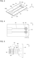
FIG. 2 is a view showing a first connector member of the connector according to Embodiment 1 mounted on the garment. -
FIG. 3 is a perspective view showing the first connector member used inEmbodiment 1. -
FIG. 4 is a plan view showing the first connector member used inEmbodiment 1. -
FIG. 5 is a view showing a second connector member of the connector according to Embodiment 1 mounted on the garment. -
FIG. 6 is a perspective view showing the second connector member used inEmbodiment 1. -
FIG. 7 is a view showing portions of the connector according toEmbodiment 1, the portions being exposed on an outer surface of the garment. -
FIG. 8 is a perspective view showing a counter connector used inEmbodiment 1. -
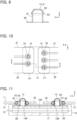
FIG. 9 is a cross-sectional view showing a counter first contact and a counter second contact of the counter connector used inEmbodiment 1. -
FIG. 10 is a partial plan view showing a fitting state between the connector according toEmbodiment 1 and the counter connector. -
FIG. 11 is a cross-sectional view taken along line A-A inFIG. 10 . -
FIG. 12 is a view showing the garment with the connector according to Embodiment 1 being mounted thereon and fitted with the counter connector. -
FIG. 13 is a perspective view showing a first connector member used inEmbodiment 2. -
FIG. 14 is a perspective view showing a second connector member used inEmbodiment 2. -
FIG. 15 is a perspective view showing a counter connector used inEmbodiment 2. -
FIG. 16 is a plan view showing a first fitting state between a connector and the counter connector inEmbodiment 2. -
FIG. 17 is a plan view showing a second fitting state between the connector and the counter connector inEmbodiment 2. -
FIG. 18 is a partial plan view showing a fitting state between a connector and a counter connector inEmbodiment 3. -
FIG. 19 is a view showing a garment on which a connector according to Embodiment 4 is mounted. -
FIG. 20 is a partial plan view showing a fitting state between the connector and a counter connector in Embodiment 4. -
FIG. 21 is a partial plan view showing a fitting state between a connector and a counter connector in Embodiment 5. -
FIG. 22 is a perspective view showing a first contact and a second contact used in Embodiment 5. -
FIG. 23 is a perspective view showing the counter connector used in Embodiment 5. -
FIG. 24 is a cross-sectional view taken along line B-B inFIG. 21 . -
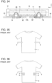
FIG. 25 is a front view showing a garment to which a conventional tightening device is attached. -
FIG. 26 is a back view showing the garment to which the conventional tightening device is attached. - Embodiments of the present invention are described below based on the accompanying drawings.
-
FIG. 1 shows a garment G on which aconnector 11 according toEmbodiment 1 is attached. The garment G is a top such as a shirt worn by a user. Theconnector 11 used as a garment-side connector is disposed on a tubular circumferential portion G1 constituted of a body part in which a torso of a user is inserted. - The
connector 11 is attached to a front body of the garment G and is composed of afirst connector member 21 and asecond connector member 31 that are spaced from each other at an interval in the circumferential direction of the circumferential portion G1. - A plurality of electrodes G2 constituting terminal members are attached on an inner peripheral surface of the circumferential portion G1 of the garment G, that is, the inner surface of the garment G that faces the body of the user when the user wears the garment G.
- In addition, a plurality of first wiring portions W1 and a plurality of second wiring portions W2 are respectively disposed between electrodes G2 and the
first connector member 21 and between electrodes G2 and thesecond connector member 31 on the inner peripheral surface of the circumferential portion G1. Specifically, of the electrodes G2, some are connected to thefirst connector member 21 via the first wiring portions W1 and the others are connected to thesecond connector member 31 via the second wiring portions W2. - For convenience, the front body of the garment G in
FIG. 1 is defined as extending along an XY plane, thefirst connector member 21 and thesecond connector member 31 are defined as being spaced in an X direction, and the direction that is perpendicular to an XY plane and is directed from the front body toward the front of the garment G is defined as a +Z direction. - The
second connector member 31 is disposed on the -X direction side of thefirst connector member 21 when the garment G is seen from the front. - As shown in
FIG. 2 , thefirst connector member 21 includes an insulatingfirst sheet member 22 extending from the +X direction toward the -X direction along an XY plane. The circumferential portion G1 of the garment G is provided with a slit G3 corresponding to thefirst connector member 21 and extending in the Y direction. By passing thefirst sheet member 22 through the slit G3, the +X directional portion of thefirst connector member 21 is placed on the inner peripheral surface side of the circumferential portion G1 of the garment G, while the -X directional portion of thefirst connector member 21 is placed on the outer peripheral surface side of the circumferential portion G1 of the garment G. - As shown in
FIG. 3 , thefirst sheet member 22 extending from the +X direction toward the -X direction includes: a mounting portion MP that is defined at a base end of thefirst sheet member 22 on the +X direction side and is to be mounted on the garment G; and a fitting portion FP that is defined at a distal end of thefirst sheet member 22 on the -X direction side and is to be fitted to acounter connector 12. - The
first sheet member 22 is provided with anembroidery pattern 23 made by sewing an embroidery thread. Theembroidery pattern 23 extends from the mounting portion MP to the fitting portion FP. A conductive thread is used as the embroidery thread forming theembroidery pattern 23, so that a plurality of firstflexible conductors 24 having electric conductivity are formed. - Each first
flexible conductor 24 includes: a linearfirst connection portion 24A disposed in the fitting portion FP of thefirst sheet member 22 and extending in the X direction; a rectangularsecond connection portion 24B disposed in the mounting portion MP of thefirst sheet member 22; and ajoint portion 24C joining thefirst connection portion 24A and thesecond connection portion 24B to each other in the X direction. - The
first connector member 21 includes a plurality offirst contacts 25 attached to the fitting portion FP of thefirst sheet member 22 and electrically connected to thefirst connection portions 24A of the firstflexible conductors 24. Thefirst contacts 25 are aligned in the Y direction in the fitting portion FP to form a contact row R2 extending in the Y direction. - Each
first contact 25 is a conductive member having a ring shape, more specifically, a donut shape, made of metal or the like, and is attached to a peripheral portion of a sheet through hole 22Athat is formed in thefirst sheet member 22 in a place where thefirst connection portion 24A of the corresponding firstflexible conductor 24 is disposed. For thefirst contact 25, a ring-shaped metal fitting called a grommet may be used, for instance. - The
first sheet member 22 is made of, for example, insulating cloth, knitted fabric, or rubber material and is a flexible member that is stretchable at least in the X direction. Thefirst contacts 25 situated in the contact row R2 can be displaced in the -X direction when a tensile force in the -X direction is exerted on the distal end of thefirst sheet member 22 on the -X direction side, as illustrated by the two-dot-dash line inFIG. 4 . An amount of displacement dL of thefirst contacts 25 varies depending on the tensile force acting on thefirst sheet member 22, and a shrinking force according to the amount of displacement dL is generated at thefirst sheet member 22 elastically stretched in the X direction. - Since the first
flexible conductors 24 are made of the embroidery thread, the firstflexible conductors 24 extending in the X direction are also configured to be stretchable in the X direction. - As shown in
FIG. 2 , the base end of thefirst connector member 21 on the +X direction side is situated on the inner peripheral surface side of the circumferential portion G1 of the garment G. Thesecond connection portions 24B of the firstflexible conductors 24 are electrically connected to the corresponding first wiring portions W1 and further to the corresponding electrodes G2 via the first wiring portions W1 on the inner peripheral surface side of the circumferential portion G1. - The distal end of the
first connector member 21 on the -X direction side is situated on the outer peripheral surface side of the circumferential portion G1 of the garment G, so that thefirst contacts 25 are exposed on the outer peripheral surface side of the circumferential portion G1. - As shown in
FIG. 5 , thesecond connector member 31 includes an insulatingsecond sheet member 32 extending from the -X direction toward the +X direction along an XY plane. The circumferential portion G1 of the garment G is provided with a slit G4 corresponding to thesecond connector member 31 and extending in the Y direction. By passing thesecond sheet member 32 through the slit G4, the -X directional portion of thesecond connector member 31 is placed on the inner peripheral surface side of the circumferential portion G1 of the garment G, while the +X directional portion of thesecond connector member 31 is placed on the outer peripheral surface side of the circumferential portion G1 of the garment G. - The
second connector member 31 has a configuration similar to thefirst connector member 21. To be more specific, as shown inFIG. 6 , thesecond sheet member 32 extending from the -X direction toward the +X direction includes: a mounting portion MP that is defined at a base end of thesecond sheet member 32 on the -X direction side and is to be mounted on the garment G; and a fitting portion FP that is defined at a distal end of thesecond sheet member 32 on the +X direction side and is to be fitted to thecounter connector 12. - The
second sheet member 32 is provided with anembroidery pattern 33 made by sewing an embroidery thread, and a plurality of secondflexible conductors 34 having electric conductivity are formed by theembroidery pattern 33. - Each second
flexible conductor 34 includes: a linearfirst connection portion 34A disposed in the fitting portion FP of thesecond sheet member 32 and extending in the X direction; a rectangularsecond connection portion 34B disposed in the mounting portion MP of thesecond sheet member 32; and ajoint portion 34C joining thefirst connection portion 34A and thesecond connection portion 34B to each other in the X direction. - The
second connector member 31 includes a plurality ofsecond contacts 35 attached to the fitting portion FP of thesecond sheet member 32 and electrically connected to thefirst connection portions 34A of the secondflexible conductors 34. Thesecond contacts 35 are aligned in the Y direction in the fitting portion FP to form a contact row R3 extending in the Y direction. - Each
second contact 35 is a donut-shaped conductive member having the same configuration as thefirst contact 25 of thefirst connector member 21 and is attached to a peripheral portion of a sheet throughhole 32A formed in thesecond sheet member 32. - The first and
second contacts - The
second sheet member 32 is made of, for example, insulating cloth, knitted fabric, or rubber material and is a flexible member that is stretchable at least in the X direction, similarly to thefirst sheet member 22 of thefirst connector member 21. Thesecond contacts 35 situated in the contact row R3 are displaced when a tensile force in the +X direction is exerted on the distal end of thesecond sheet member 32 on the +X direction side, and an X-directional shrinking force is generated at thesecond sheet member 32 elastically stretched in the X direction. - Since the second
flexible conductors 34 are made of the embroidery thread, the secondflexible conductors 34 extending in the X direction are also configured to be stretchable in the X direction. - As shown in
FIG. 5 , the base end of thesecond connector member 31 on the -X direction side is situated on the inner peripheral surface side of the circumferential portion G1 of the garment G. Thesecond connection portions 34B of the secondflexible conductors 34 are electrically connected to the corresponding second wiring portions W2 and further to the corresponding electrodes G2 via the second wiring portions W2 on the inner peripheral surface side of the circumferential portion G1. - The distal end of the
second connector member 31 on the +X direction side is situated on the outer peripheral surface side of the circumferential portion G1 of the garment G, so that thesecond contacts 35 are exposed on the outer peripheral surface side of the circumferential portion G1. - In the state where no external force other than gravity acts on the garment G and the
connector 11, the contact row R2 of thefirst connector member 21 and the contact row R3 of thesecond connector member 31 both exposed on the outer peripheral surface side of the circumferential portion G1 of the garment G are spaced from each other in the X direction by a distance L1, as shown inFIG. 7 . - The electrodes G2 attached on the inner peripheral surface of the circumferential portion G1 of the garment G shown in
FIG. 1 are used to acquire biological data of the user who is wearing the garment G and can be made of a metal material but may also be formed by weaving-in of a conductive thread; alternatively, use may be made of the electrode G2 having a conductive layer formed by printing or the like on a surface of an insulating resin film. - Fiber wiring formed by weaving-in of a conductive thread may be used for the first wiring portions W1 connecting the
second connection portions 24B of the firstflexible conductors 24 of thefirst connector member 21 to the corresponding electrodes G2 and the second wiring portions W2 connecting thesecond connection portions 34B of the secondflexible conductors 34 of thesecond connector member 31 to the corresponding electrodes G2 on the inner peripheral surface of the circumferential portion G1 of the garment G. Alternatively, wiring having a conductive layer formed by printing or the like on a surface of an insulating resin film may be used for the first wiring portions W1 and the second wiring portions W2. -
FIG. 8 shows thecounter connector 12 to be fitted to theconnector 11. Thecounter connector 12 includes: an insulatinghousing 13 having rigidity; and a plurality of counterfirst contacts 14 and a plurality of countersecond contacts 15 both retained by thehousing 13. Thecounter connector 12 is used as a module-side connector. - The
housing 13 has aconnector opposing surface 13A of flat shape that extends along an XY plane and faces in the +Z direction. The counterfirst contacts 14 and the countersecond contacts 15 protrude in the +Z direction from theconnector opposing surface 13A. - The counter
first contacts 14 are aligned in the Y direction in a +X directional portion of thehousing 13 to form a contact row R11 extending in the Y direction. The countersecond contacts 15 are aligned in the Y direction in a -X directional portion of thehousing 13 to form a contact row R12 extending in the Y direction at a position spaced from the contact row R11 formed of the counterfirst contacts 14 in the -X direction by a distance L2. - The distance L2 in the X direction between the contact rows R11 and R12 is set to be shorter than the distance L1 in the X direction between the contact row R2 of the
first connector member 21 and the contact row R3 of thesecond connector member 31 in the state where no external force other than gravity acts on the garment G and theconnector 11. - The counter
first contacts 14 and the countersecond contacts 15 have the same configuration and, as shown inFIG. 9 , each include a tubular portion S1 of cylindrical shape extending in the +Z direction and a flange S2 extending along an XY plane from the -Z directional end of the tubular portion S1. The tubular portion S1 is provided at its +Z directional end with a guide portion S3 of conical shape that tapers toward the +Z direction, and the guide portion S3 is provided at its -Z directional end with an overhanging portion S4 of annular shape that protrudes in the radial direction with respect to the tubular portion S1. The outer diameter of the overhanging portion S4 is set to be smaller than the inner diameter of the donut-shapedfirst contact 25 of thefirst connector member 21 and the inner diameter of the donut-shapedsecond contact 35 of thesecond connector member 31, and the tubular portion S1 and the guide portion S3 are formed to be insertable into the donut-shaped first andsecond contacts - When the
connector 11 is fitted to thecounter connector 12, first, a user puts on the garment G, and thecounter connector 12 is positioned between thefirst connector member 21 and thesecond connector member 31. - Next, the -X directional end of the
first sheet member 22 of thefirst connector member 21 and the +X directional end of thesecond sheet member 32 of thesecond connector member 31 that are exposed on the outer peripheral surface side of the circumferential portion G1 of the garment G are pulled to approach each other, whereby thefirst sheet member 22 and thesecond sheet member 32 are stretched in the X direction to the position where thefirst contacts 25 of thefirst connector member 21 are situated on the +Z direction side of the counterfirst contacts 14 of thecounter connector 12 and thesecond contacts 35 of thesecond connector member 31 are situated on the +Z direction side of the countersecond contacts 15 of thecounter connector 12. - In this state, the fitting portion FP of the
first sheet member 22 of thefirst connector member 21 and the fitting portion FP of thesecond sheet member 32 of thesecond connector member 31 are moved in the -Z direction toward theconnector opposing surface 13A of thehousing 13 of thecounter connector 12 from the +Z direction. Consequently, as shown inFIG. 10 , the counterfirst contacts 14 of thecounter connector 12 are separately inserted into and fitted to the corresponding donut-shapedfirst contacts 25 of thefirst connector member 21, and the countersecond contacts 15 of thecounter connector 12 are separately inserted into and fitted to the corresponding donut-shapedsecond contacts 35 of thesecond connector member 31. - Then, when X-directional tensile forces acting on the
first sheet member 22 of thefirst connector member 21 and thesecond sheet member 32 of thesecond connector member 31 are released, thefirst sheet member 22 and thesecond sheet member 32 shrink in the X direction, thefirst contacts 25 of thefirst connector member 21 and thesecond contacts 35 of thesecond connector member 31 are electrically connected to the counterfirst contacts 14 and the countersecond contacts 15 of thecounter connector 12, respectively, and theconnector 11 is fitted to thecounter connector 12. -
FIG. 11 shows theconnector 11 and thecounter connector 12 thus fitted together. Thehousing 13 of thecounter connector 12 has amodule substrate 17 therein, and the flanges S2 of the counterfirst contacts 14 and the flanges S2 of the countersecond contacts 15 are mounted on themodule substrate 17. - In the state where the tubular portion S1 and the guide portion S3 of the counter
first contact 14 protrude in the +Z direction from theconnector opposing surface 13A via a through-hole 13B of thehousing 13 and are inserted in the corresponding donut-shapedfirst contact 25 of thefirst connector member 21, a shrinking force is generated at thefirst sheet member 22 due to release of the tensile force acting on thefirst sheet member 22. - Likewise, in the state where the tubular portion S1 and the guide portion S3 of the counter
second contact 15 protrude in the +Z direction from theconnector opposing surface 13A via a through-hole 13B of thehousing 13 and are inserted in the corresponding donut-shapedsecond contact 35 of thesecond connector member 31, a shrinking force is generated at thesecond sheet member 32 due to release of the tensile force acting on thesecond sheet member 32. - Consequently, an inner peripheral portion, on the -X direction side, of the
first contact 25 of thefirst connector member 21 makes contact with an outer peripheral portion, on the -X direction side, of the counterfirst contact 14 of thecounter connector 12 at a predetermined contact pressure, and an inner peripheral portion, on the +X direction side, of thesecond contact 35 of thesecond connector member 31 makes contact with an outer peripheral portion, on the +X direction side, of the countersecond contact 15 of thecounter connector 12 at a predetermined contact pressure. - As a result, the
first contacts 25 of thefirst connector member 21 are electrically connected to the counterfirst contacts 14 of thecounter connector 12 separately, and thesecond contacts 35 of thesecond connector member 31 are electrically connected to the countersecond contacts 15 of thecounter connector 12 separately. - As shown in
FIG. 2 , thesecond connection portions 24B of the firstflexible conductors 24 of thefirst connector member 21 are electrically connected to the corresponding electrodes G2 via the first wiring portions W1 of the garment G, separately. - Likewise, as shown in
FIG. 5 , thesecond connection portions 34B of the secondflexible conductors 34 of thesecond connector member 31 are electrically connected to the corresponding electrodes G2 via the second wiring portions W2 of the garment G, separately. - Therefore, it is possible to, via the
first contacts 25 and thesecond contacts 35 of theconnector 11, electrically connect the counterfirst contacts 14 and the countersecond contacts 15 of thecounter connector 12 separately to the electrodes G2 disposed on the inner peripheral surface side of the circumferential portion G1 of the garment G. - Hence, by mounting a predetermined electronic circuit on the
module substrate 17 housed in thecounter connector 12, the user's biological data acquired through the electrodes G2 can be measured by the electronic circuit or transmitted from the electronic circuit to a remote measurement device. - Since the distance L2 in the X direction between the contact rows R11 and R12 of the
counter connector 12 is set to be shorter than the distance L1 in the X direction between the contact row R2 of thefirst connector member 21 and the contact row R3 of thesecond connector member 31 with no external force other than gravity acting on the garment G and theconnector 11, thefirst sheet member 22 and thesecond sheet member 32 are each in a state of being stretched in the X direction in theconnector 11 fitted to thecounter connector 12. - Accordingly, X-directional shrinking forces act on the
first sheet member 22 and thesecond sheet member 32, and this tightens the circumferential portion G1 of the garment G to which thefirst connector member 21 and thesecond connector member 31 are attached, thus making the circumferential length of the circumferential portion G1 shorter as shown inFIG. 12 . - This configuration makes it possible to cause the electrodes G2 disposed on the inner peripheral surface side of the circumferential portion G1 of the garment G to be closely attached to the body of the user who is wearing the garment G.
- Thus, it is possible to carry out both establishment of electric connection of the electrodes G2 attached to the garment G to the counter
first contacts 14 and the countersecond contacts 15 of thecounter connector 12 and tightening of the garment G only by mounting theconnector 11 according toEmbodiment 1 on the garment G and fitting thecounter connector 12 to theconnector 11. In other words, it is possible to acquire biological data of the user who is wearing the garment G with high accuracy and perform electric processing by use of thecounter connector 12 that is the module-side connector. - When acquisition of the user's biological data is not carried out, the
counter connector 12 may be detached from the garment G to release the fitting between theconnector 11 and thecounter connector 12, whereby the garment G returns to the initial condition shown inFIG. 1 , which is loose clothes without a feel of tightness. - In
Embodiment 1 above, thesecond connection portions 24B of the firstflexible conductors 24 of thefirst sheet member 22 and thesecond connection portions 34B of the secondflexible conductors 34 of thesecond sheet member 32 are electrically connected to the corresponding first and second wiring portions W1 and W2 on the inner peripheral surface side of the circumferential portion G1 of the garment G, respectively; however, the invention is not limited thereto. - For example, the
second connection portions 24B of the firstflexible conductors 24 of thefirst sheet member 22 and thesecond connection portions 34B of the secondflexible conductors 34 of thesecond sheet member 32 may be disposed on the outer peripheral surface side of the circumferential portion G1 of the garment G and electrically connected to the corresponding first and second wiring portions W1 and W2 disposed on the inner peripheral surface side of the circumferential portion G1 by sewing with a conductive thread. This configuration eliminates the need of the slits G3 and G4 formed in the circumferential portion G1 of the garment G. - In the
connector 11 according toEmbodiment 1, only by mounting theconnector 11 on the garment G and fitting the same to thecounter connector 12, contact forces are imparted between thefirst contacts 25 and the counterfirst contacts 14 of thecounter connector 12 and between thesecond contacts 35 and the countersecond contacts 15 of thecounter connector 12, and also a tightening force is imparted to the circumferential portion G1 of the garment G. In this respect, the contact forces and tightening force imparted can be configured to be adjustable. -
FIG. 13 shows afirst connector member 51 used in aconnector 41 according toEmbodiment 2. Thefirst connector member 51 includes an insulatingfirst sheet member 52 extending along an XY plane. Thefirst sheet member 52 includes: a mounting portion MP defined at a base end of thefirst sheet member 52 on the +X direction side; and a fitting portion FP defined at a distal end of thefirst sheet member 52 on the -X direction side. - The
first sheet member 52 is provided with anembroidery pattern 53 made by sewing an embroidery thread, and a conductive thread is used as the embroidery thread forming theembroidery pattern 53, so that a plurality of firstflexible conductors 54 having electric conductivity are formed. Each firstflexible conductor 54 includes afirst connection portion 54A disposed in the fitting portion FP of thefirst sheet member 52, asecond connection portion 54B disposed in the mounting portion MP of thefirst sheet member 52, and ajoint portion 54C joining thefirst connection portion 54A and thesecond connection portion 54B to each other, as with the firstflexible conductor 24 inEmbodiment 1. - The
first connector member 51 includes a plurality offirst contacts 55 that correspond to the firstflexible conductors 54 and that are attached to the fitting portion FP of thefirst sheet member 52. Eachfirst contact 55 includes twofirst contact parts 55A aligned at an interval along the X direction, and those twofirst contact parts 55A are both electrically connected to thefirst connection portion 54A of the corresponding firstflexible conductor 54. - The
first contact parts 55A disposed on the -X direction side in thefirst contacts 55 form a first contact row R51 aligned in the Y direction and extending in the Y direction, and thefirst contact parts 55A disposed on the +X direction side in thefirst contacts 55 form a second contact row R52 aligned in the Y direction and extending in the Y direction. -
FIG. 14 shows asecond connector member 61 used in theconnector 41 according toEmbodiment 2. Thesecond connector member 61 includes an insulatingsecond sheet member 62 extending along an XY plane. Thesecond sheet member 62 includes: a mounting portion MP defined at a base end of thesecond sheet member 62 on the -X direction side; and a fitting portion FP defined at a distal end of thesecond sheet member 62 on the +X direction side. - The
second sheet member 62 is provided with anembroidery pattern 63 made by sewing an embroidery thread, and a conductive thread is used as the embroidery thread forming theembroidery pattern 63, so that a plurality of secondflexible conductors 64 having electric conductivity are formed. Each secondflexible conductor 64 includes afirst connection portion 64A disposed in the fitting portion FP of thesecond sheet member 62, asecond connection portion 64B disposed in the mounting portion MP of thesecond sheet member 62, and a j ointportion 64C joining thefirst connection portion 64A and thesecond connection portion 64B to each other, as with the secondflexible conductor 34 inEmbodiment 1. - The
second connector member 61 includes a plurality ofsecond contacts 65 that correspond to the secondflexible conductors 64 and that are attached to the fitting portion FP of thesecond sheet member 62. Eachsecond contact 65 includes twosecond contact parts 65A aligned at an interval along the X direction, and those twosecond contact parts 65A are both electrically connected to thefirst connection portion 64A of the corresponding secondflexible conductor 64. - The
second contact parts 65A disposed on the +X direction side in thesecond contacts 65 form a first contact row R61 aligned in the Y direction and extending in the Y direction, and thesecond contact parts 65A disposed on the -X direction side in thesecond contacts 65 form a second contact row R62 aligned in the Y direction and extending in the Y direction. - The
first sheet member 52 and thesecond sheet member 62 are made of, for example, insulating cloth, knitted fabric, or rubber material and are flexible members stretchable at least in the X direction, as with the first andsecond sheet members Embodiment 1. - The two
first contact parts 55A of eachfirst contact 55 and the twosecond contact parts 65A of eachsecond contact 65 are conductive members having a ring shape, more specifically, a donut shape, made of metal or the like, and may be formed of a ring-shaped metal fitting called a grommet for instance, similarly to thefirst contact 25 and thesecond contact 35 inEmbodiment 1. - The
first contact part 55A is attached to a peripheral portion of a sheet through hole 52Athat is formed in thefirst sheet member 52 in a place where thefirst connection portion 54A of the corresponding firstflexible conductor 54 is situated, and thesecond contact part 65A is attached to a peripheral portion of a sheet through hole 62Athat is formed in thesecond sheet member 62 in a place where thefirst connection portion 64A of the corresponding secondflexible conductor 64 is situated. -
FIG. 15 shows acounter connector 42 to be fitted to theconnector 41. Thecounter connector 42 has the same structure as thecounter connector 12 inEmbodiment 1 except for its shape elongated in the X direction. Specifically, thecounter connector 42 includes: an insulatinghousing 43 having rigidity; and a plurality of counterfirst contacts 44 and a plurality of countersecond contacts 45 protruding in the +Z direction from aconnector opposing surface 43A of thehousing 43, theconnector opposing surface 43A extending along an XY plane and facing the +Z direction. - The counter
first contacts 44 are aligned in the Y direction in a +X directional portion of thehousing 43 to form a contact row R41 extending in the Y direction, and the countersecond contacts 45 are aligned in the Y direction in a -X directional portion of thehousing 43 to form a contact row R42 extending in the Y direction. - The counter
first contacts 44 and the countersecond contacts 45 have the same structure as the counterfirst contacts 14 and the countersecond contacts 15 used inEmbodiment 1 and shown inFIG. 9 . - Also in the
connector 41 according toEmbodiment 2, thefirst sheet member 52 of thefirst connector member 51 and thesecond sheet member 62 of thesecond connector member 61 are stretched in the X direction, and in this state, the counterfirst contacts 44 of thecounter connector 42 are fitted to thefirst contacts 55 of thefirst connector member 51, while the countersecond contacts 45 of thecounter connector 42 are fitted to thesecond contacts 65 of thesecond connector member 61, as with theconnector 11 ofEmbodiment 1. - Subsequently, X-directional tensile forces acting on the
first sheet member 52 of thefirst connector member 51 and thesecond sheet member 62 of thesecond connector member 61 are released, whereupon thecounter connector 42 is fitted to theconnector 41. - In the meantime, the
first contacts 55 of thefirst connector member 51 each have the twofirst contact parts 55A aligned at an interval along the X direction, so that the first contact row R51 and the second contact row R52 are formed. Therefore, a shrinking force generated at thefirst sheet member 52 when theconnector 41 is fitted to thecounter connector 42 varies depending on, into thefirst contact parts 55 A of which row, the first contact row R51 or the second contact row R52, the counterfirst contacts 44 of thecounter connector 42 are inserted. - Likewise, the
second contacts 65 of thesecond connector member 61 each have the twosecond contact parts 65A aligned at an interval along the X direction, so that the first contact row R61 and the second contact row R62 are formed. Therefore, a shrinking force generated at thesecond sheet member 62 when theconnector 41 is fitted to thecounter connector 42 varies depending on, into thesecond contact parts 65A of which row, the first contact row R61 or the second contact row R62, the countersecond contacts 45 of thecounter connector 42 are inserted. - For instance, the
counter connector 42 can be fitted to theconnector 41 by fitting the counterfirst contacts 44 forming the contact row R41 of thecounter connector 42 to thefirst contact parts 55 A forming the first contact row R51 of thefirst connector member 51 and fitting the countersecond contacts 45 forming the contact row R42 of thecounter connector 42 to thesecond contact parts 65A forming the first contact row R61 of thesecond connector member 61, as shown inFIG. 16 . - In this case, the X-directional stretching amounts of the
first sheet member 52 and thesecond sheet member 62 are relatively small, and hence, the shrinking forces generated at thefirst sheet member 52 and thesecond sheet member 62 are relatively weak. As a consequence, thefirst contact parts 55A and thesecond contact parts 65A make contact with the counterfirst contacts 44 and the countersecond contacts 45 with relatively weak forces, respectively, so that a relatively weak tightening force acts on the circumferential portion G1 of the garment G. - On the other hand, the
counter connector 42 can be fitted to theconnector 41 also by, for example, fitting the counterfirst contacts 44 forming the contact row R41 of thecounter connector 42 to thefirst contact parts 55A forming the second contact row R52 of thefirst connector member 51 and fitting the countersecond contacts 45 forming the contact row R42 of thecounter connector 42 to thesecond contact parts 65A forming the second contact row R62 of thesecond connector member 61, as shown inFIG. 17 . - In this case, the X-directional stretching amounts of the first sheet member 52b and the
second sheet member 62 are relatively large, and hence, the shrinking forces generated at thefirst sheet member 52 and thesecond sheet member 62 are relatively strong. As a consequence, thefirst contact parts 55A and thesecond contact parts 65A make contact with the counterfirst contacts 44 and the countersecond contacts 45 with relatively strong forces, respectively, so that a relatively strong tightening force acts on the circumferential portion G1 of the garment G. - Thus, one of the first contact row R51 and the second contact row R52 of the
first connector member 51 and one of the first contact row R61 and the second contact row R62 of thesecond connector member 61 are selected depending on the body frame of the user who wears the garment G, and then thecounter connector 42 is fitted to theconnector 41, thus adjusting the contact forces and tightening force imparted. - In
Embodiment 2 above, thefirst connector member 51 has the first contact row R51 and the second contact row R52, and thesecond connector member 61 has the first contact row R61 and the second contact row R62; however, each of the first andsecond connector members - The number of contact rows of the
first connector member 51 may be the same as or different from the number of contact rows of thesecond connector member 61. - In
Embodiment 1, thecounter connector 12 is fitted to theconnector 11 in the state where thehousing 13 of thecounter connector 12 is disposed on the -Z direction side of the -X directional portion of thefirst sheet member 22 where thefirst contacts 25 are exposed and the +X directional portion of thesecond sheet member 32 where thesecond contacts 35 are exposed, that is, disposed on the side closer to the garment G, as shown inFIGS. 10 and 11 ; however, the invention is not limited thereto. - For instance, as shown in
FIG. 18 , thecounter connector 12 may be disposed on the +Z direction side of the -X directional portion of thefirst sheet member 22 and the +X directional portion of thesecond sheet member 32, that is, on the opposite side from the garment G, to fit thecounter connector 12 to theconnector 11. - It should be noted that, in this case, the
counter connector 12 is fitted to theconnector 11 from the +Z direction with its position being turned over in the Z direction such that the counterfirst contacts 14 and the countersecond contacts 15 protrude in the -Z direction. - In
Embodiment 1, thefirst contacts 25 are retained by the stretchablefirst sheet member 22 of thefirst connector member 21, and thesecond contacts 35 are retained by the stretchablesecond sheet member 32 of thesecond connector member 31; however, the invention is not limited thereto. -
FIG. 19 shows a garment G on which aconnector 11A according to Embodiment 4 is attached. The garment G is the same as that used inEmbodiment 1. The electrodes G2 and the first and second wiring portions W1 and W2 are disposed on the inner peripheral surface of the tubular circumferential portion G1. - The
connector 11A is a connector corresponding to theconnector 11 according toEmbodiment 1 but, of the first andsecond connector members second connector member 31 is omitted, and thesecond contacts 35 are retained on the circumferential portion G1 of the garment G. - The
second contacts 35 are directly connected to the second wiring portions W2 on the inner peripheral surface side of the circumferential portion G1 of the garment G. - In the
connector 11A of Embodiment 4, thefirst sheet member 22 is stretched in the X direction by pulling the -X directional end of thefirst sheet member 22 of thefirst connector member 21 in the -X direction, and in this state, the counterfirst contacts 14 of thecounter connector 12 are fitted to thefirst contacts 25 of thefirst connector member 21, while the countersecond contacts 15 of thecounter connector 12 are fitted to thesecond contacts 35 retained on the circumferential portion G1 of the garment G, as shown inFIG. 20 . - Subsequently, an X-directional tensile force acting on the
first sheet member 22 of thefirst connector member 21 is released, whereupon thecounter connector 12 is fitted to theconnector 11A. - Even when the
second contacts 35 are retained by the garment G, a shrinking force is generated at thefirst sheet member 22 stretched in the X direction, and this makes it possible to bring thefirst contacts 25 and thesecond contacts 35 into contact with the counterfirst contacts 14 and the countersecond contacts 15 of thecounter connector 12 at a predetermined contact pressure, respectively, and to allow a tightening force to act on the circumferential portion G1 of the garment G where theconnector 11A is disposed. - It should be noted that, of the first and
second connector members Embodiment 1, thefirst connector member 21 may be omitted with thefirst contacts 25 being retained on the circumferential portion G1 of the garment G. In this case, the counterfirst contacts 14 of thecounter connector 12 are inserted into thefirst contacts 25 retained on the circumferential portion G1 of the garment G, and the countersecond contacts 15 of thecounter connector 12 are inserted into thesecond contacts 35 of thesecond connector member 31. - In
Embodiments 1 to 4 above, thefirst contacts 25, thesecond contacts 35, thefirst contact parts 55A of thefirst contacts 55, and thesecond contact parts 65A of thesecond contacts 65 all have a so-called donut shape; however, the shape is not limited to a donut shape, and for example, a conductive member of flat plate and ring shape made of metal or the like may also be used. -
FIG. 21 shows a fitting state between aconnector 71 according to Embodiment 5 and acounter connector 72. Theconnector 71 includes afirst connector member 81 having a plurality offirst contacts 85 protruding in the +Z direction and asecond connector member 91 having a plurality ofsecond contacts 95 protruding in the +Z direction. - The
first connector member 81 has an insulatingfirst sheet member 82 extending in an XY plane, and thefirst sheet member 82 is provided with a plurality of first flexible conductors 84 formed using a conductive thread. Thefirst contacts 85 are retained by thefirst sheet member 82 and connected to the first flexible conductors 84. - The
second connector member 91 has an insulatingsecond sheet member 92 extending in an XY plane, and thesecond sheet member 92 is provided with a plurality of secondflexible conductors 94 formed using a conductive thread. Thesecond contacts 95 are retained by thesecond sheet member 92 and connected to the secondflexible conductors 94. - The
first sheet member 82 and thesecond sheet member 92 are made of, for example, insulating cloth, knitted fabric, or rubber material and are flexible members stretchable at least in the X direction, as with the first andsecond sheet members Embodiment 1. - The
first contacts 85 and thesecond contacts 95 each include a tubular portion T1 of cylindrical shape extending in the +Z direction and a flange T2 extending along an XY plane from the -Z directional end of the tubular portion T1, as shown inFIG. 22 . Thefirst contacts 85 and thesecond contacts 95 are retained by thefirst sheet member 82 and thesecond sheet member 92 by partially inserting their flanges T2 through thefirst sheet member 82 and thesecond sheet member 92 and bending the inserted parts to the -Z direction side, and are thereby electrically connected to the corresponding first flexible conductors 84 and the corresponding secondflexible conductors 94, respectively. - The tubular portion T1 is provided at its +Z directional end with a guide portion T3 of conical shape that tapers toward the +Z direction.
- As shown in
FIG. 23 , thecounter connector 72 includes: an insulatinghousing 73 having rigidity; and a plurality of counterfirst contacts 74 and a plurality of countersecond contacts 75 both retained by thehousing 73. - The
housing 73 has aconnector opposing surface 73A of flat shape that extends along an XY plane and faces in the -Z direction. The counterfirst contacts 74 and the countersecond contacts 75 are retained by thehousing 73 so as to be exposed in the -Z direction from theconnector opposing surface 73A. - The counter
first contacts 74 are aligned in the Y direction in a +X directional portion of thehousing 73 to form a contact row R8 extending in the Y direction, and the countersecond contacts 75 are aligned in the Y direction in a -X directional portion of thehousing 73 to form a contact row R9 extending in the Y direction. - The counter
first contacts 74 and the countersecond contacts 75 are conductive members of flat ring shape made of metal or the like. Each of the counterfirst contacts 74 and the countersecond contacts 75 is provided at its center with an insertion hole that allows insertion of the tubular portion T1 and the guide portion T3 of the corresponding one of thefirst contacts 85 and thesecond contacts 95. - When the
connector 71 is fitted to thecounter connector 72, first, the -X directional end of thefirst sheet member 82 of thefirst connector member 81 and the +X directional end of thesecond sheet member 92 of thesecond connector member 91 are pulled to approach each other, whereby thefirst sheet member 82 and thesecond sheet member 92 are stretched in the X direction, as withEmbodiment 1. - In this state, the tubular portions T1 and the guide portions T3 of the
first contacts 85 of thefirst connector member 81 are inserted into the ring-shaped counterfirst contacts 74 of thecounter connector 72, and the tubular portions T1 and the guide portions T3 of thesecond contacts 95 of thesecond connector member 91 are inserted into the ring-shaped countersecond contacts 75 of thecounter connector 72. - Then, when X-directional tensile forces acting on the
first sheet member 82 of thefirst connector member 81 and thesecond sheet member 92 of thesecond connector member 91 are released, thefirst sheet member 82 and thesecond sheet member 92 shrink in the X direction, thefirst contacts 85 of thefirst connector member 81 and thesecond contacts 95 of thesecond connector member 91 are electrically connected to the counterfirst contacts 74 and the countersecond contacts 75 of thecounter connector 72, respectively, and theconnector 71 is fitted to thecounter connector 72. -
FIG. 24 shows theconnector 71 and thecounter connector 72 thus fitted together. Upon shrinking of the first andsecond sheet members first contact 85 of thefirst connector member 81 makes contact with an inner peripheral portion, on the +X direction side, of the ring-shaped counterfirst contact 74 of thecounter connector 72 at a predetermined contact pressure, and an outer peripheral portion, on the -X direction side, of the tubular portion T1 of thesecond contact 95 of thesecond connector member 91 makes contact with an inner peripheral portion, on the -X direction side, of the ring-shaped countersecond contact 75 of thecounter connector 72 at a predetermined contact pressure. - As a result, the
first contacts 85 of thefirst connector member 81 and thesecond contacts 95 of thesecond connector member 91 can be electrically connected to the counterfirst contacts 74 and the countersecond contacts 75 of thecounter connector 72, respectively. - In addition, upon shrinking of the first and
second sheet members connector 71 is disposed. - Thus, even when the
first contacts 85 and thesecond contacts 95 that protrude in the +Z direction are attached to the stretchablefirst sheet member 82 of thefirst connector member 81 and the stretchablesecond sheet member 92 of thesecond connector member 91, respectively, and the ring-shaped counterfirst contacts 74 and the ring-shaped countersecond contacts 75 are disposed in therigid housing 73 of thecounter connector 72, the same effects as those of theconnector 11 ofEmbodiment 1 can be obtained. - In
Embodiments 1 to 5 above, the number of thefirst contacts second contacts connector first contacts second contacts counter connector - While the electrodes G2 attached on the inner peripheral surface of the circumferential portion G1 of the garment G are, as the terminal member, connected to the
connector Embodiments 1 to 5 above, various sensors used to acquire user's biological data may serve as the terminal member. Fitting thecounter connector connector - While the
connector Embodiments 1 to 5 above, the mounting object is not limited to the garment G, and theconnector - For the mounting object, use may be made of a wearing article having a tubular or ring-shaped circumferential portion into which a part of a user's body is inserted, such as a belly band, a head band, and a wrist band. When the
connector connector
Claims (21)
- A connector (11, 11A, 41, 71) that is configured to be mounted on a mounting object (G) and fitted to a counter connector (12, 42, 72) in which a counter first contact (14, 44, 74) and a counter second contact (15, 45, 75) are retained by a housing (13, 43, 73) having rigidity and an insulating property, the connector comprising:a first contact (25, 55, 85) and a second contact (35, 65, 95) that are spaced from each other in a predetermined direction and are configured to be respectively fitted to the counter first contact and the counter second contact when the connector is fitted to the counter connector; anda first sheet member (22, 52, 82) that has flexibility and an insulating property and is stretchable at least in the predetermined direction, a base end of the first sheet member in the predetermined direction being mounted on the mounting object at a position opposite from the second contact with respect to the first contact, and a distal end of the first sheet member in the predetermined direction having the first contact retained therein,wherein the second contact (35, 65, 95) is configured to be retained by the mounting object via a second sheet member (32, 62, 92) having flexibility and an insulating property or directly retained by the mounting object, andwith at least the first sheet member being elastically stretched in the predetermined direction, the connector is fitted to the counter connector, and due to a shrinking force generated at the first sheet member, the first contact and the second contact are electrically connected to the counter first contact and the counter second contact, respectively.
- The connector according to claim 1 comprising the second sheet member (32, 62, 92),wherein the second sheet member is stretchable at least in the predetermined direction, a base end of the second sheet member in the predetermined direction being configured to be mounted on the mounting object (G) at a position opposite from the first contact with respect to the second contact, and a distal end of the second sheet member in the predetermined direction having the second contact (35, 65, 95) retained therein, andwith each of the first sheet member (22, 52, 82) and the second sheet member (32, 62, 92) being elastically stretched in the predetermined direction, the connector is fitted to the counter connector, and due to shrinking forces generated at the first sheet member and the second sheet member, the first contact and the second contact are electrically connected to the counter first contact and the counter second contact, respectively.
- The connector according to claim 1 comprising a first flexible conductor (24, 54, 84) disposed on the first sheet member (22, 52, 82) and is configured to electrically connect the first contact (25, 55, 85) to a first wiring portion (W1) of the mounting object.
- The connector according to claim 2 comprising a second flexible conductor (34, 64, 94) disposed on the second sheet member (32, 62, 92) and is configured to electrically connect the second contact (35, 65, 95) to a second wiring portion (W2) of the mounting object.
- The connector according to claim 3,wherein the first contact (55) includes a plurality of first contact parts (55A) aligned at intervals along the predetermined direction and electrically connected to one another, andone of the plurality of first contact parts is selectively fitted to the counter first contact.
- The connector according to claim 4,wherein the second contact (65) includes a plurality of second contact parts (65A) aligned at intervals along the predetermined direction and electrically connected to one another, andone of the plurality of second contact parts is selectively fitted to the counter second contact.
- The connector according to any one of claims 1, 3 and 5,
wherein the second contact (35) is configured to be retained by the mounting object (G) and directly connected to a second wiring portion (W2) of the mounting object. - The connector according to claim 3 or 5 comprising a plurality of the first contacts (25, 55, 85) and a plurality of the first flexible conductors (24, 54, 84) both aligned in a direction perpendicular to the predetermined direction,
wherein the plurality of the first contacts are electrically connected to a plurality of the counter first contacts of the counter connector, separately. - The connector according to claim 4 or 6 comprising a plurality of the second contacts (35, 65, 95) and a plurality of the second flexible conductors (34, 64, 94) both aligned in a direction perpendicular to the predetermined direction,
wherein the plurality of the second contacts are electrically connected to a plurality of the counter second contacts of the counter connector, separately. - The connector according to any one of claims 3, 5 and 8,wherein the first sheet member (22, 52, 82) includes a fitting portion (FP) disposed in the distal end and overlapping with the counter connector when the connector is fitted to the counter connector, and a mounting portion (MP) disposed in the base end and configured to be mounted on the mounting object,the first contact (25, 55, 85) is retained in the fitting portion (FP) of the first sheet member, andthe first flexible conductor (24, 54, 84) includes a first connection portion (24A, 54A) disposed in the fitting portion and electrically connected to the first contact, a second connection portion (24B, 54B) disposed in the mounting portion and configured to be electrically connected to the first wiring portion of the mounting object, and a joint portion (24C, 54C) joining the first connection portion and the second connection portion to each other.
- The connector according to any one of claims 4, 6 and 9,wherein the second sheet member (32, 62, 92) includes a fitting portion (FP) disposed in the distal end and overlapping with the counter connector when the connector is fitted to the counter connector, and a mounting portion (MP) disposed in the base end and configured to be mounted on the mounting object,the second contact (35, 65, 95) is retained in the fitting portion (FP) of the second sheet member, andthe second flexible conductor (34, 64, 94) includes a first connection portion (34A, 64A) disposed in the fitting portion and electrically connected to the second contact, a second connection portion (34B, 64B) disposed in the mounting portion and configured to be electrically connected to the second wiring portion of the mounting object, and a joint portion (34C, 64C) joining the first connection portion and the second connection portion to each other.
- The connector according to any one of claims 3, 5, 8 and 10,wherein the first sheet member (22, 52, 82) is made of cloth, knitted fabric, or a rubber material, andthe first flexible conductor (24, 54, 84) is formed of a conductive thread embroidered on or woven into the first sheet member.
- The connector according to any one of claims 4, 6, 9 and 11,wherein the second sheet member (32, 62, 92) is made of cloth, knitted fabric, or a rubber material, andthe second flexible conductor (34, 64, 94) is formed of a conductive thread embroidered on or woven into the second sheet member.
- The connector according to any one of claims 1-13,wherein the counter first contact (14, 44) and the counter second contact (15, 45) each have a tubular portion (S1) of cylindrical shape protruding in the fitting direction,the first contact (25, 55) and the second contact (35, 65) are each formed of a conductive member of ring shape, andan inner peripheral portion of the conductive member makes contact with an outer peripheral portion of the tubular portion corresponding to the conductive member due to the shrinking force generated at the first sheet member.
- The connector according to any one of claims 1-13,wherein the first contact (85) and the second contact (95) each have a tubular portion of cylindrical shape protruding in the fitting direction,the counter first contact (74) and the counter second contact (75) are each formed of a conductive member of ring shape, andan outer peripheral portion of the tubular portion makes contact with an inner peripheral portion of the conductive member corresponding to the tubular portion due to the shrinking force generated at the first sheet member.
- A connector assembly comprising:the connector (11, 11A, 41, 71) according to any one of claims 1-15; andthe counter connector (12, 42, 72) to which the connector is fitted.
- A wearing article serving as the mounting object on which the connector (11, 11A, 41, 71) according to any one of claims 1-15 is mounted.
- The wearing article according to claim 17,wherein the wearing article has a circumferential portion (G1) of tubular shape or ring shape into which a part of a user's body is inserted, andthe connector (11, 11A, 41, 71) is mounted on the circumferential portion with taking a circumferential direction of the circumferential portion as the predetermined direction.
- The wearing article according to claim 18,
wherein the wearing article has a slit (G3, G4) that allows the first sheet member (22, 52, 82) to be passed therethrough from an inner peripheral surface of the circumferential portion (G1) to an outer peripheral surface thereof. - The wearing article according to claim 18 or 19,
wherein the wearing article is provided with a plurality of terminal members disposed on an inner peripheral surface of the circumferential portion (G1) and connected to the first contact and the second contact of the connector. - The wearing article according to claim 20, wherein each of the plurality of terminal members is constituted of an electrode (G2) or a sensor.
Applications Claiming Priority (1)
| Application Number | Priority Date | Filing Date | Title |
|---|---|---|---|
| JP2023082241A JP2024165760A (en) | 2023-05-18 | 2023-05-18 | Connector, connector assembly and wearing article |
Publications (2)
| Publication Number | Publication Date |
|---|---|
| EP4465450A1 true EP4465450A1 (en) | 2024-11-20 |
| EP4465450B1 EP4465450B1 (en) | 2025-04-16 |
Family
ID=90469773
Family Applications (1)
| Application Number | Title | Priority Date | Filing Date |
|---|---|---|---|
| EP24166131.3A Active EP4465450B1 (en) | 2023-05-18 | 2024-03-26 | Connector, connector assembly, and wearing article |
Country Status (4)
| Country | Link |
|---|---|
| US (1) | US20240388026A1 (en) |
| EP (1) | EP4465450B1 (en) |
| JP (1) | JP2024165760A (en) |
| CN (1) | CN119009527A (en) |
Families Citing this family (1)
| Publication number | Priority date | Publication date | Assignee | Title |
|---|---|---|---|---|
| JP7897987B1 (en) * | 2025-06-16 | 2026-07-30 | Nok株式会社 | wiring structure |
Citations (2)
| Publication number | Priority date | Publication date | Assignee | Title |
|---|---|---|---|---|
| JP2019123959A (en) | 2018-01-15 | 2019-07-25 | 東洋紡株式会社 | clothing |
| WO2020165546A1 (en) * | 2019-02-14 | 2020-08-20 | Genius Objects | Monitoring system |
Family Cites Families (9)
| Publication number | Priority date | Publication date | Assignee | Title |
|---|---|---|---|---|
| JP7232143B2 (en) * | 2019-07-19 | 2023-03-02 | 日本航空電子工業株式会社 | connector |
| JP7348016B2 (en) * | 2019-10-01 | 2023-09-20 | 日本航空電子工業株式会社 | connector |
| JP7807994B2 (en) * | 2022-06-27 | 2026-01-28 | 日本航空電子工業株式会社 | Sheet-shaped conductive member and connector |
| JP2024076024A (en) * | 2022-11-24 | 2024-06-05 | 日本航空電子工業株式会社 | connector |
| JP2024094608A (en) * | 2022-12-28 | 2024-07-10 | 日本航空電子工業株式会社 | Connectors and connection methods |
| JP2024165753A (en) * | 2023-05-18 | 2024-11-28 | 日本航空電子工業株式会社 | Connector, connector assembly, connection structure, and connection method |
| JP2025024378A (en) * | 2023-08-07 | 2025-02-20 | 日本航空電子工業株式会社 | connector |
| JP2025073238A (en) * | 2023-10-26 | 2025-05-13 | 日本航空電子工業株式会社 | Connector assembly and connector |
| JP2025132682A (en) * | 2024-02-29 | 2025-09-10 | 日本航空電子工業株式会社 | connector |
-
2023
- 2023-05-18 JP JP2023082241A patent/JP2024165760A/en active Pending
-
2024
- 2024-02-21 US US18/583,023 patent/US20240388026A1/en active Pending
- 2024-02-28 CN CN202410225519.3A patent/CN119009527A/en active Pending
- 2024-03-26 EP EP24166131.3A patent/EP4465450B1/en active Active
Patent Citations (2)
| Publication number | Priority date | Publication date | Assignee | Title |
|---|---|---|---|---|
| JP2019123959A (en) | 2018-01-15 | 2019-07-25 | 東洋紡株式会社 | clothing |
| WO2020165546A1 (en) * | 2019-02-14 | 2020-08-20 | Genius Objects | Monitoring system |
Also Published As
| Publication number | Publication date |
|---|---|
| CN119009527A (en) | 2024-11-22 |
| EP4465450B1 (en) | 2025-04-16 |
| JP2024165760A (en) | 2024-11-28 |
| US20240388026A1 (en) | 2024-11-21 |
Similar Documents
| Publication | Publication Date | Title |
|---|---|---|
| US20240277266A1 (en) | Sensor holder device for invasive biosensors | |
| US9259182B2 (en) | Portable electronic device | |
| EP4465450B1 (en) | Connector, connector assembly, and wearing article | |
| US8750959B2 (en) | Wearing apparel with a sensor for measuring a physiological signal | |
| EP4465451A1 (en) | Connector, connector assembly, connecting structure, and connecting method | |
| US7753686B2 (en) | Velcro connector | |
| CN110249714A (en) | Printed circuit board biosensing garment connector | |
| US11996663B2 (en) | Bonding device, bonding structure for wearable device and node device for forming sensing point on signal connecting line thereof | |
| US20150119675A1 (en) | Garment | |
| KR101897216B1 (en) | Clothe having Physiological signal sensing system | |
| US10548219B2 (en) | Stress relaxation substrate and textile type device | |
| EP4311031B1 (en) | Garment on which a connector is mounted, and method for assembling such a garment | |
| EP4311032B1 (en) | Method of manufacturing sheet type conductive member, sheet type conductive member, connector, garment, and connector mounting method | |
| EP4395474B1 (en) | Connector and connector assembly | |
| US20250141140A1 (en) | Connector assembly and connector | |
| EP4311033B1 (en) | Sheet type conductive member, connector, garment, and connector mounting method | |
| US10310558B2 (en) | Apparatus and method for computing node and seat connection for conductive fabric | |
| CN113164086B (en) | Blood pressure measuring device charging connector | |
| EP4451477A1 (en) | Connector assembly, garment, and electrical device with pad | |
| JP2018050650A (en) | Connection component for wearable apparatus and wearable apparatus | |
| KR101961728B1 (en) | Smart clothe having Physiological signal sensing function | |
| JP2022500189A (en) | Textile equipment configured to work with electronic devices | |
| EP4447231B1 (en) | Connecting method, wiring member, and garment | |
| WO2019155238A1 (en) | Textile electronic contact | |
| WO2021205188A1 (en) | Electronic unit for a garment |
Legal Events
| Date | Code | Title | Description |
|---|---|---|---|
| PUAI | Public reference made under article 153(3) epc to a published international application that has entered the european phase |
Free format text: ORIGINAL CODE: 0009012 |
|
| STAA | Information on the status of an ep patent application or granted ep patent |
Free format text: STATUS: REQUEST FOR EXAMINATION WAS MADE |
|
| 17P | Request for examination filed |
Effective date: 20240326 |
|
| AK | Designated contracting states |
Kind code of ref document: A1 Designated state(s): AL AT BE BG CH CY CZ DE DK EE ES FI FR GB GR HR HU IE IS IT LI LT LU LV MC ME MK MT NL NO PL PT RO RS SE SI SK SM TR |
|
| GRAP | Despatch of communication of intention to grant a patent |
Free format text: ORIGINAL CODE: EPIDOSNIGR1 |
|
| STAA | Information on the status of an ep patent application or granted ep patent |
Free format text: STATUS: GRANT OF PATENT IS INTENDED |
|
| INTG | Intention to grant announced |
Effective date: 20250122 |
|
| GRAS | Grant fee paid |
Free format text: ORIGINAL CODE: EPIDOSNIGR3 |
|
| GRAA | (expected) grant |
Free format text: ORIGINAL CODE: 0009210 |
|
| STAA | Information on the status of an ep patent application or granted ep patent |
Free format text: STATUS: THE PATENT HAS BEEN GRANTED |
|
| AK | Designated contracting states |
Kind code of ref document: B1 Designated state(s): AL AT BE BG CH CY CZ DE DK EE ES FI FR GB GR HR HU IE IS IT LI LT LU LV MC ME MK MT NL NO PL PT RO RS SE SI SK SM TR |
|
| REG | Reference to a national code |
Ref country code: GB Ref legal event code: FG4D |
|
| REG | Reference to a national code |
Ref country code: CH Ref legal event code: EP Ref country code: DE Ref legal event code: R096 Ref document number: 602024000064 Country of ref document: DE |
|
| REG | Reference to a national code |
Ref country code: IE Ref legal event code: FG4D |
|
| REG | Reference to a national code |
Ref country code: NL Ref legal event code: MP Effective date: 20250416 |
|
| PG25 | Lapsed in a contracting state [announced via postgrant information from national office to epo] |
Ref country code: NL Free format text: LAPSE BECAUSE OF FAILURE TO SUBMIT A TRANSLATION OF THE DESCRIPTION OR TO PAY THE FEE WITHIN THE PRESCRIBED TIME-LIMIT Effective date: 20250416 |
|
| REG | Reference to a national code |
Ref country code: AT Ref legal event code: MK05 Ref document number: 1786460 Country of ref document: AT Kind code of ref document: T Effective date: 20250416 |
|
| PG25 | Lapsed in a contracting state [announced via postgrant information from national office to epo] |
Ref country code: FI Free format text: LAPSE BECAUSE OF FAILURE TO SUBMIT A TRANSLATION OF THE DESCRIPTION OR TO PAY THE FEE WITHIN THE PRESCRIBED TIME-LIMIT Effective date: 20250416 Ref country code: ES Free format text: LAPSE BECAUSE OF FAILURE TO SUBMIT A TRANSLATION OF THE DESCRIPTION OR TO PAY THE FEE WITHIN THE PRESCRIBED TIME-LIMIT Effective date: 20250416 Ref country code: PT Free format text: LAPSE BECAUSE OF FAILURE TO SUBMIT A TRANSLATION OF THE DESCRIPTION OR TO PAY THE FEE WITHIN THE PRESCRIBED TIME-LIMIT Effective date: 20250818 |
|
| REG | Reference to a national code |
Ref country code: LT Ref legal event code: MG9D |
|
| PG25 | Lapsed in a contracting state [announced via postgrant information from national office to epo] |
Ref country code: GR Free format text: LAPSE BECAUSE OF FAILURE TO SUBMIT A TRANSLATION OF THE DESCRIPTION OR TO PAY THE FEE WITHIN THE PRESCRIBED TIME-LIMIT Effective date: 20250717 Ref country code: NO Free format text: LAPSE BECAUSE OF FAILURE TO SUBMIT A TRANSLATION OF THE DESCRIPTION OR TO PAY THE FEE WITHIN THE PRESCRIBED TIME-LIMIT Effective date: 20250716 |
|
| PG25 | Lapsed in a contracting state [announced via postgrant information from national office to epo] |
Ref country code: PL Free format text: LAPSE BECAUSE OF FAILURE TO SUBMIT A TRANSLATION OF THE DESCRIPTION OR TO PAY THE FEE WITHIN THE PRESCRIBED TIME-LIMIT Effective date: 20250416 |
|
| PG25 | Lapsed in a contracting state [announced via postgrant information from national office to epo] |
Ref country code: BG Free format text: LAPSE BECAUSE OF FAILURE TO SUBMIT A TRANSLATION OF THE DESCRIPTION OR TO PAY THE FEE WITHIN THE PRESCRIBED TIME-LIMIT Effective date: 20250416 |
|
| PG25 | Lapsed in a contracting state [announced via postgrant information from national office to epo] |
Ref country code: HR Free format text: LAPSE BECAUSE OF FAILURE TO SUBMIT A TRANSLATION OF THE DESCRIPTION OR TO PAY THE FEE WITHIN THE PRESCRIBED TIME-LIMIT Effective date: 20250416 |
|
| PG25 | Lapsed in a contracting state [announced via postgrant information from national office to epo] |
Ref country code: AT Free format text: LAPSE BECAUSE OF FAILURE TO SUBMIT A TRANSLATION OF THE DESCRIPTION OR TO PAY THE FEE WITHIN THE PRESCRIBED TIME-LIMIT Effective date: 20250416 |
|
| PG25 | Lapsed in a contracting state [announced via postgrant information from national office to epo] |
Ref country code: RS Free format text: LAPSE BECAUSE OF FAILURE TO SUBMIT A TRANSLATION OF THE DESCRIPTION OR TO PAY THE FEE WITHIN THE PRESCRIBED TIME-LIMIT Effective date: 20250716 |
|
| PG25 | Lapsed in a contracting state [announced via postgrant information from national office to epo] |
Ref country code: IS Free format text: LAPSE BECAUSE OF FAILURE TO SUBMIT A TRANSLATION OF THE DESCRIPTION OR TO PAY THE FEE WITHIN THE PRESCRIBED TIME-LIMIT Effective date: 20250816 |
|
| PG25 | Lapsed in a contracting state [announced via postgrant information from national office to epo] |
Ref country code: LV Free format text: LAPSE BECAUSE OF FAILURE TO SUBMIT A TRANSLATION OF THE DESCRIPTION OR TO PAY THE FEE WITHIN THE PRESCRIBED TIME-LIMIT Effective date: 20250416 |
|
| PG25 | Lapsed in a contracting state [announced via postgrant information from national office to epo] |
Ref country code: DK Free format text: LAPSE BECAUSE OF FAILURE TO SUBMIT A TRANSLATION OF THE DESCRIPTION OR TO PAY THE FEE WITHIN THE PRESCRIBED TIME-LIMIT Effective date: 20250416 Ref country code: SM Free format text: LAPSE BECAUSE OF FAILURE TO SUBMIT A TRANSLATION OF THE DESCRIPTION OR TO PAY THE FEE WITHIN THE PRESCRIBED TIME-LIMIT Effective date: 20250416 |
|
| REG | Reference to a national code |
Ref country code: DE Ref legal event code: R097 Ref document number: 602024000064 Country of ref document: DE |
|
| PG25 | Lapsed in a contracting state [announced via postgrant information from national office to epo] |
Ref country code: CZ Free format text: LAPSE BECAUSE OF FAILURE TO SUBMIT A TRANSLATION OF THE DESCRIPTION OR TO PAY THE FEE WITHIN THE PRESCRIBED TIME-LIMIT Effective date: 20250416 |
|
| PG25 | Lapsed in a contracting state [announced via postgrant information from national office to epo] |
Ref country code: EE Free format text: LAPSE BECAUSE OF FAILURE TO SUBMIT A TRANSLATION OF THE DESCRIPTION OR TO PAY THE FEE WITHIN THE PRESCRIBED TIME-LIMIT Effective date: 20250416 |
|
| PG25 | Lapsed in a contracting state [announced via postgrant information from national office to epo] |
Ref country code: SK Free format text: LAPSE BECAUSE OF FAILURE TO SUBMIT A TRANSLATION OF THE DESCRIPTION OR TO PAY THE FEE WITHIN THE PRESCRIBED TIME-LIMIT Effective date: 20250416 |
|
| PG25 | Lapsed in a contracting state [announced via postgrant information from national office to epo] |
Ref country code: IT Free format text: LAPSE BECAUSE OF FAILURE TO SUBMIT A TRANSLATION OF THE DESCRIPTION OR TO PAY THE FEE WITHIN THE PRESCRIBED TIME-LIMIT Effective date: 20250416 |
|
| PLBE | No opposition filed within time limit |
Free format text: ORIGINAL CODE: 0009261 |
|
| STAA | Information on the status of an ep patent application or granted ep patent |
Free format text: STATUS: NO OPPOSITION FILED WITHIN TIME LIMIT |
|
| REG | Reference to a national code |
Ref country code: CH Ref legal event code: L10 Free format text: ST27 STATUS EVENT CODE: U-0-0-L10-L00 (AS PROVIDED BY THE NATIONAL OFFICE) Effective date: 20260225 |
|
| 26N | No opposition filed |
Effective date: 20260119 |
|
| PGFP | Annual fee paid to national office [announced via postgrant information from national office to epo] |
Ref country code: DE Payment date: 20260128 Year of fee payment: 3 |
|
| PGFP | Annual fee paid to national office [announced via postgrant information from national office to epo] |
Ref country code: FR Payment date: 20260209 Year of fee payment: 3 |
|
| PG25 | Lapsed in a contracting state [announced via postgrant information from national office to epo] |
Ref country code: LT Free format text: LAPSE BECAUSE OF FAILURE TO SUBMIT A TRANSLATION OF THE DESCRIPTION OR TO PAY THE FEE WITHIN THE PRESCRIBED TIME-LIMIT Effective date: 20250416 |
|
| PG25 | Lapsed in a contracting state [announced via postgrant information from national office to epo] |
Ref country code: SE Free format text: LAPSE BECAUSE OF FAILURE TO SUBMIT A TRANSLATION OF THE DESCRIPTION OR TO PAY THE FEE WITHIN THE PRESCRIBED TIME-LIMIT Effective date: 20250416 |