EP4465430A1 - Battery block - Google Patents
Battery block Download PDFInfo
- Publication number
- EP4465430A1 EP4465430A1 EP23898211.0A EP23898211A EP4465430A1 EP 4465430 A1 EP4465430 A1 EP 4465430A1 EP 23898211 A EP23898211 A EP 23898211A EP 4465430 A1 EP4465430 A1 EP 4465430A1
- Authority
- EP
- European Patent Office
- Prior art keywords
- battery block
- cell array
- battery
- coupling
- plate
- Prior art date
- Legal status (The legal status is an assumption and is not a legal conclusion. Google has not performed a legal analysis and makes no representation as to the accuracy of the status listed.)
- Pending
Links
Images




Classifications
-
- H—ELECTRICITY
- H01—ELECTRIC ELEMENTS
- H01M—PROCESSES OR MEANS, e.g. BATTERIES, FOR THE DIRECT CONVERSION OF CHEMICAL ENERGY INTO ELECTRICAL ENERGY
- H01M50/00—Constructional details or processes of manufacture of the non-active parts of electrochemical cells other than fuel cells, e.g. hybrid cells
- H01M50/20—Mountings; Secondary casings or frames; Racks, modules or packs; Suspension devices; Shock absorbers; Transport or carrying devices; Holders
- H01M50/258—Modular batteries; Casings provided with means for assembling
-
- H—ELECTRICITY
- H01—ELECTRIC ELEMENTS
- H01M—PROCESSES OR MEANS, e.g. BATTERIES, FOR THE DIRECT CONVERSION OF CHEMICAL ENERGY INTO ELECTRICAL ENERGY
- H01M50/00—Constructional details or processes of manufacture of the non-active parts of electrochemical cells other than fuel cells, e.g. hybrid cells
- H01M50/20—Mountings; Secondary casings or frames; Racks, modules or packs; Suspension devices; Shock absorbers; Transport or carrying devices; Holders
- H01M50/204—Racks, modules or packs for multiple batteries or multiple cells
- H01M50/207—Racks, modules or packs for multiple batteries or multiple cells characterised by their shape
- H01M50/209—Racks, modules or packs for multiple batteries or multiple cells characterised by their shape adapted for prismatic or rectangular cells
-
- H—ELECTRICITY
- H01—ELECTRIC ELEMENTS
- H01M—PROCESSES OR MEANS, e.g. BATTERIES, FOR THE DIRECT CONVERSION OF CHEMICAL ENERGY INTO ELECTRICAL ENERGY
- H01M50/00—Constructional details or processes of manufacture of the non-active parts of electrochemical cells other than fuel cells, e.g. hybrid cells
- H01M50/20—Mountings; Secondary casings or frames; Racks, modules or packs; Suspension devices; Shock absorbers; Transport or carrying devices; Holders
- H01M50/204—Racks, modules or packs for multiple batteries or multiple cells
-
- H—ELECTRICITY
- H01—ELECTRIC ELEMENTS
- H01M—PROCESSES OR MEANS, e.g. BATTERIES, FOR THE DIRECT CONVERSION OF CHEMICAL ENERGY INTO ELECTRICAL ENERGY
- H01M50/00—Constructional details or processes of manufacture of the non-active parts of electrochemical cells other than fuel cells, e.g. hybrid cells
- H01M50/20—Mountings; Secondary casings or frames; Racks, modules or packs; Suspension devices; Shock absorbers; Transport or carrying devices; Holders
- H01M50/262—Mountings; Secondary casings or frames; Racks, modules or packs; Suspension devices; Shock absorbers; Transport or carrying devices; Holders with fastening means, e.g. locks
-
- H—ELECTRICITY
- H01—ELECTRIC ELEMENTS
- H01M—PROCESSES OR MEANS, e.g. BATTERIES, FOR THE DIRECT CONVERSION OF CHEMICAL ENERGY INTO ELECTRICAL ENERGY
- H01M50/00—Constructional details or processes of manufacture of the non-active parts of electrochemical cells other than fuel cells, e.g. hybrid cells
- H01M50/20—Mountings; Secondary casings or frames; Racks, modules or packs; Suspension devices; Shock absorbers; Transport or carrying devices; Holders
- H01M50/262—Mountings; Secondary casings or frames; Racks, modules or packs; Suspension devices; Shock absorbers; Transport or carrying devices; Holders with fastening means, e.g. locks
- H01M50/264—Mountings; Secondary casings or frames; Racks, modules or packs; Suspension devices; Shock absorbers; Transport or carrying devices; Holders with fastening means, e.g. locks for cells or batteries, e.g. straps, tie rods or peripheral frames
-
- H—ELECTRICITY
- H01—ELECTRIC ELEMENTS
- H01M—PROCESSES OR MEANS, e.g. BATTERIES, FOR THE DIRECT CONVERSION OF CHEMICAL ENERGY INTO ELECTRICAL ENERGY
- H01M2220/00—Batteries for particular applications
- H01M2220/10—Batteries in stationary systems, e.g. emergency power source in plant
-
- H—ELECTRICITY
- H01—ELECTRIC ELEMENTS
- H01M—PROCESSES OR MEANS, e.g. BATTERIES, FOR THE DIRECT CONVERSION OF CHEMICAL ENERGY INTO ELECTRICAL ENERGY
- H01M2220/00—Batteries for particular applications
- H01M2220/20—Batteries in motive systems, e.g. vehicle, ship, plane
-
- Y—GENERAL TAGGING OF NEW TECHNOLOGICAL DEVELOPMENTS; GENERAL TAGGING OF CROSS-SECTIONAL TECHNOLOGIES SPANNING OVER SEVERAL SECTIONS OF THE IPC; TECHNICAL SUBJECTS COVERED BY FORMER USPC CROSS-REFERENCE ART COLLECTIONS [XRACs] AND DIGESTS
- Y02—TECHNOLOGIES OR APPLICATIONS FOR MITIGATION OR ADAPTATION AGAINST CLIMATE CHANGE
- Y02E—REDUCTION OF GREENHOUSE GAS [GHG] EMISSIONS, RELATED TO ENERGY GENERATION, TRANSMISSION OR DISTRIBUTION
- Y02E60/00—Enabling technologies; Technologies with a potential or indirect contribution to GHG emissions mitigation
- Y02E60/10—Energy storage using batteries
Definitions
- the present invention relates to a battery block that can simplify the structure of a battery pack to improve space utilization and reduce production costs and can be easily expanded to various specifications to match the capacity of the battery pack.
- secondary batteries can be recharged and have been researched and developed in recent years due to their potential for miniaturization and large capacity.
- the demand for the secondary battery as an energy source is increasing rapidly due to the technological development and increasing demand for mobile devices, electric vehicles, and energy storage systems, which are emerging in response to the need for environmental protection.
- Secondary batteries are categorized into coin batteries, cylindrical batteries, prismatic batteries, and pouch batteries based on the shape of the battery case.
- the electrode assembly mounted inside the battery case is a charging and discharging power generation element consisting of a stacked structure of electrodes and separators.
- Secondary batteries are a form of battery pack, where a plurality of battery cells can form one group.
- Battery packs increase energy density and can be used in devices that require high energy, such as in electric vehicles.
- Battery packs electrically connect a plurality of battery cells to produce a specified power output, cool the battery cells that increase in temperature during operation, and have various safety devices to respond to emergencies such as ignition, etc.
- the present invention is directed to provide a battery block that can simplify the structure of a battery pack to improve space utilization and reduce production costs, and that can be easily expanded to various specifications to match the capacity of the battery pack.
- the present invention relates to a battery block, characterized in one example by including a cell array comprising a plurality of prismatic cells arranged in a row; a pair of side plates disposed on two sides of the cell array, respectively; and a pair of end plates disposed on a front surface and rear surface of the cell array, respectively, wherein both ends of the end plates in a wide direction both end plates are fixed against side brackets provided at both ends of the side plates in a length direction, and the interconnection of the end plates and the side plates constrains the cell array into one block.
- the side plates may comprise a single plate bent in an " U" shape with an open top to form a space therein.
- the side plate may comprise concave surfaces on both sides of the bent plate and may be provided at least one bonding rib formed by mutually bonding the concave surfaces facing each other along the length direction.
- the top of the side plate may have a bent upper flange that contacts a top surface of the cell array.
- the side bracket may comprise a coupling groove into which a welding bolt protruding from the end plate is inserted, and the welding bolt and the coupling groove may be interconnected by welding.
- the welding bolts and the coupling grooves may be provided in pairs up and down, with reference to the center in the height direction of the cell array.
- the side bracket may be provided with the coupling grooves on both the left and right sides with reference to the center in the width direction of the side plate.
- another cell array arranged along the width direction may share the side plate, and a plurality of cell arrays may extend along the width direction by fixing welding bolts provided in a pair of end plates disposed at the front surface and rear surface of the another cell array, respectively, with respect to the coupling grooves of the side bracket.
- the end plate may include an end bracket that is fixed to the pack case.
- the side bracket may comprise an end bracket fixed to the pack case.
- the end bracket may comprise a coupling surface parallel to the width direction, and the coupling surface may comprise one or more coupling holes formed therein.
- the end bracket may comprise a reinforcing rib perpendicular to the coupling surface.
- the battery block of the present invention having the configuration as described above has a simple structure in which the end plates, which are joined through side brackets provided on the side plates, constrain the front, rear and sides of a cell array of a plurality of prismatic cells into a single block.
- the space utilization rate of the battery pack can be improved, and the production cost can be reduced.
- the battery block of the present invention is lightweight and exhibits excellent mechanical strength as the side plates are made of a single plate bent in an " U" shape, and the side plates of such a battery block replace the configuration of cross beams in conventional battery packs.
- a battery pack with the battery block of the present invention can further increase the energy density in the same volume due to the elimination of the cross beam structure.
- the battery block of the present invention has a structure in which a plurality of battery blocks is connected such that neighboring cell arrays share a single side plate, the total number of side plates only needs to be one more than the number of cell arrays, further improving the space efficiency of a battery pack mounting the battery block of the present invention.
- the present invention relates to a battery block, which, in one example, includes a cell array comprising a plurality of prismatic cells arranged in a row; a pair of side plates disposed on both sides of the cell array, respectively; and a pair of end plates disposed on the front and rear surfaces of the cell array, respectively.
- the both ends of the end plates in a width direction are fixed against side brackets provided at both ends of the side plates in a length direction, and by such interconnection of the end plates and the side plates, the cell array is constrained as a block.
- the side plate may comprise a single plate bent in the form of an " U " with an open top to form a space therein.
- the battery block of the present invention with the configuration as described above has a simple structure in which the end plates, which are joined through side brackets provided on the side plates, constrain the front, rear and sides of a cell array of a plurality of prismatic cells into a single block.
- the space utilization rate of the battery pack can be improved, and the production cost can be reduced.
- the battery block of the present invention is lightweight and exhibits excellent mechanical strength as the side plates are made of a single plate bent into an " U " shape, and the side plates of the battery block replace the configuration of cross beams in conventional battery packs.
- battery packs with the battery block of the present invention will be able to further increase the energy density in the same volume due to the elimination of the cross beam structure.
- FIG. 1 is a drawing illustrating a battery block according to one embodiment of the present invention.
- FIG. 2 is an exploded perspective view of the battery block of FIG. 1 .
- a battery block 10 of the present invention includes a pair of side plates 200 and a pair of end plates 300 that are joined thereto to form a parallelepiped-shaped space, and a cell array 100 accommodated in the parallelepiped space.
- the cell array 100 refers to one group of cells comprising a plurality of prismatic cells 110 arranged in a row.
- Each prismatic cell 110 is a finished prismatic secondary battery capable of charging and discharging independently, and in the embodiment shown, 12 prismatic cells 110 are shown together to form a single cell array 100. All of the prismatic cells 110 are typically constructed to the same specifications, and the prismatic cells 110 aligned in a row have the overall shape of a parallelepiped.
- the illustrated prismatic cell 110 corresponds to a unidirectional prismatic cell 110 having both positive and negative electrode terminals 112 disposed on the upper surface, and also having a venting device 114 between the pair of electrode terminals 112.
- the venting device 114 is a safety valve that ruptures to relieve the pressure inside the prismatic cell 110 when anexceed level of pressure is applied, and may comprise, for example, a notched rupture disk made of a thin plate-like member of a metal material.
- the pressure inside the enclosed prismatic cell 110 rises, the pressure causes tensile deformation across the thin plate and tears the less strong notch portions, releasing the pressure inside the prismatic cell 110.
- the electrode terminals 112 of the prismatic cells 110 on the cell array 100 may be arranged to have the same polarity in a series of rows or alternating opposite polarities to facilitate electrical connections in parallel or series.
- alignment of the plurality of prismatic cells 110 in a row does not necessarily mean alignment of the polarity of the electrode terminals 112 in a row.
- a pair of side plates 200 are disposed on two sides of the cell array 100, respectively, and a pair of end plates 300 are disposed on the front and rear surfaces of the cell array 100, respectively. Both ends of the end plates 300 in the width direction (W) are fixed against side brackets 210 provided at both ends of the side plates 200 in a length direction (L), and the interconnection of the end plates 300 and the side plates 200 constrains the cell array 100 as one block.
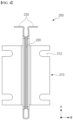
- FIG. 3 is a drawing illustrating side plate 200
- FIG. 4 is a cross-sectional view through an incision along line "A-A" in FIG. 3 .
- the illustrated side plate 200 comprises a single plate bent into an " U " shape with an open top to form a space within. By bending a single plate into an " U " shape with an open top, the side plate 200 is lightweight and exhibits excellent mechanical strength.
- the side plate 200 has concave surfaces 222 on both sides of the bent plate, and the facing concave surfaces 222 are interjoined to form bonding ribs 220.
- These bonding ribs 220 are provided at least one along the length direction L of the side plate 200, and in the embodiment shown, a total of three bonding ribs 220 are formed at both ends and in the center of the side plate 200.
- a single plate bent in an " U " shape may have excellent durability and strength against compression and tension in the length direction L due to the bending structure, but may be relatively weak against forces in the height direction (H).
- the bonding ribs 220 improve the stiffness of the side plate 200 against the height direction (H) force by connecting the concave surface 222 and the concave surface 222 on both sides of the side plate 200 by welding, riveting, or the like.
- the side plate 200 By such a structure of the side plate 200, namely, a single plate structure bent in the form of an " U " and a structure of concave surface 222 interconnected with each other, the side plate 200 has a light weight and strong mechanical strength. Accordingly, in the battery block 10 of the present invention, the side plate 200 replaces the configuration of the cross beam conventionally provided in the battery pack, and the simplified structure of the battery pack enables the space utilization rate of the battery pack to be improved, further increasing the energy density in the same volume, and reducing the production cost.
- the top of the side plate 200 is formed with a bent upper flange 230 that contacts the top surface of the cell array 100.
- the upper flange 230 creates a downward fixation force that presses the cell array 100 to the bottom when the battery block 10 is installed in the pack case 600.
- the structure by which the battery block 10 of the present invention is installed in the pack case 600 will be described in more detail later with reference to FIGS. 8 and 9 .
- FIG. 5 is an enlarged view of the coupling structure between the side plate 200 and the end plate 300.
- a side bracket 210 provided on the side plate 200 has a coupling groove 212 into which a welding bolt 310 protruding from the end plate 300 is inserted, and the welding bolt 310 and the coupling groove 212 are joined to each other by welding.
- the welding bolts 310 and the coupling grooves 212 may be provided in an up-down pair with respect to the center of the height direction H of the cell array 100.
- the end bracket 400 provided on the end plate 300 and the side plate 200 has a coupling surface 410 parallel to the width direction W, and one or more coupling holes 412 are formed on the coupling surface 410 of the end bracket 400.
- the coupling surface 410 of the end bracket 400 engages a mounting portion 640 provided in the pack case 600 (see FIG. 9 ), and the battery block 10 is fixed to the pack case 600 by joining or binding the end bracket 400 to the mounting portion 640 of the pack case 600 through the coupling holes 412.
- the end bracket 400 may include reinforcing ribs 420, such as in the form of a right triangle perpendicular to the coupling surface 410, to provide additional strength to height direction H loading.
- one or more concave surfaces 320 similar to the concave surfaces 222 of the side plates 200, may be bent and formed to reinforce the rigidity of the end plate 300 itself, and the top of the end plate 300 may also be provided with an upper flange 330 for stable fixation of the cell array 100.
- the battery block 10 of the present invention has a simple structure in which the end plates 300, which are coupled through side brackets 210 provided on the side plates 200, constrain the front and rear and sides of the cell array 100 comprising a plurality of prismatic cells 110 as a single block.
- the simplified structure of the battery block 10 can improve the space utilization of the battery pack and reduce production costs.
- the battery block 10 of the present invention is lightweight and exhibits good mechanical strength as the side plates 200 are made of a single plate bent in an " U" shape, and the side plates 200 of the battery block 10 replace the configuration of cross beams conventionally provided in battery packs.
- FIG. 6 is a drawing of a battery block 10 according to another embodiment of the present invention
- FIG. 7 is a drawing of a structure in which the battery block 10 of FIG. 4 extends in the width direction W.
- the battery block 10 of the present invention is expandable by any number of cell arrays 100 along the width direction W through the side plates 200 and side brackets 210.
- a second embodiment of the present invention describes an embodiment of such expansion of the battery block 10.
- FIGS. 8 and 9 are exemplary drawings illustrating a structure for fixing a battery block 10 of the present invention to a pack case 600.
- the pack case 600 in which the plurality of battery blocks 10 are installed includes a base plate 610 forming a bottom surface, side frames 620 forming walls along all sides of the base plate 610, and a top cover 630 enclosing the top surface of the pack case 600.
- the pack case 600 shown illustrates an example of two battery modules 500 with side plates 200 and end plates 300 joined together in a grid configuration to form a row of three cell arrays 100 (one assembly of a plurality of connected battery blocks according to a first embodiment will be referred to herein as a battery module).
- One battery module 500 in which the three cell arrays 100 are aligned in a row, has end brackets 400 exposed along the end plates 300 at the front and rear, and one end bracket 400 also exposed on the side brackets 210 between the end plates 300.
- the pack case 600 is provided with rail-shaped mounting portions 640 corresponding to the coupling surfaces 410 of the end brackets 400 that project to the front and rear of the battery module 500.
- the mounting portion 640 includes a pair of side mounting portions 642 coupled to or integrally formed with the side frame 620, and a center mounting portion 644 arranged across the center of the base plate 610.
- the coupling surfaces 410 of the end brackets 400 face the mounting portions 640 of the pack case 600, and all of the battery blocks 10 are fixed to the pack case 600 by joining or binding the end brackets 400 to the mounting portions 640 of the pack case 600 through the coupling holes 412.
- the side plates 200, and by extension, the upper flanges 230, 330, which are bent and formed on the top of the end plates 300, automatically generate a downward fixation force that presses the cell array 100 against the base plate 610, thereby ensuring that the cell array 100 is firmly pressed to the base plate 610.
- the contact between the cell array 100 and the base plate 610 plays an important role in facilitating the transfer of heat generated by the cell array 100 to the base plate 610. Therefore, it would be advantageous for the upper flanges 230, 330 to generate sufficient downward fixation force if the tolerances are managed in such a way that there is a small amount of gap between the coupling surface 410 of the end bracket 400 and the mounting portion 640 when the battery block 10, or battery module 500, is placed in the pack case 600.
Landscapes
- Chemical & Material Sciences (AREA)
- Chemical Kinetics & Catalysis (AREA)
- Electrochemistry (AREA)
- General Chemical & Material Sciences (AREA)
- Battery Mounting, Suspending (AREA)
Abstract
Description
- The present invention relates to a battery block that can simplify the structure of a battery pack to improve space utilization and reduce production costs and can be easily expanded to various specifications to match the capacity of the battery pack.
- This application claims the benefit of priority based on
Korean Patent Application No. 10-2022-0163083, filed on November 29, 2022 - Unlike primary batteries, secondary batteries can be recharged and have been researched and developed in recent years due to their potential for miniaturization and large capacity. The demand for the secondary battery as an energy source is increasing rapidly due to the technological development and increasing demand for mobile devices, electric vehicles, and energy storage systems, which are emerging in response to the need for environmental protection.
- Secondary batteries are categorized into coin batteries, cylindrical batteries, prismatic batteries, and pouch batteries based on the shape of the battery case. In the secondary battery, the electrode assembly mounted inside the battery case is a charging and discharging power generation element consisting of a stacked structure of electrodes and separators.
- Secondary batteries are a form of battery pack, where a plurality of battery cells can form one group. Battery packs increase energy density and can be used in devices that require high energy, such as in electric vehicles. Battery packs electrically connect a plurality of battery cells to produce a specified power output, cool the battery cells that increase in temperature during operation, and have various safety devices to respond to emergencies such as ignition, etc.
- Increasing the energy density per unit volume is a major challenge for battery packs, which in turn comes down to how efficiently the space inside the battery pack can be utilized. This means more battery cells need to be able to mount into the same pack space, and making the structure of the battery pack as simple as possible is a valid way to do this.
- In addition, it is advantageous to simplify the structure of the battery pack in order to reduce the production cost of the battery pack, and it is also necessary to design a structure that can be easily expanded to battery packs of various capacities.
- The present invention is directed to provide a battery block that can simplify the structure of a battery pack to improve space utilization and reduce production costs, and that can be easily expanded to various specifications to match the capacity of the battery pack.
- However, the technical problem to be solved by the present invention is not limited to the above-described problem, and other problems not mentioned can be clearly understood by a person skilled in the art from the description of the invention described below.
- The present invention relates to a battery block, characterized in one example by including a cell array comprising a plurality of prismatic cells arranged in a row; a pair of side plates disposed on two sides of the cell array, respectively; and a pair of end plates disposed on a front surface and rear surface of the cell array, respectively, wherein both ends of the end plates in a wide direction both end plates are fixed against side brackets provided at both ends of the side plates in a length direction, and the interconnection of the end plates and the side plates constrains the cell array into one block.
- In one embodiment of the present invention, the side plates may comprise a single plate bent in an " U" shape with an open top to form a space therein.
- Further, the side plate may comprise concave surfaces on both sides of the bent plate and may be provided at least one bonding rib formed by mutually bonding the concave surfaces facing each other along the length direction.
- Also, the top of the side plate may have a bent upper flange that contacts a top surface of the cell array.
- In one embodiment of the present invention, the side bracket may comprise a coupling groove into which a welding bolt protruding from the end plate is inserted, and the welding bolt and the coupling groove may be interconnected by welding.
- The welding bolts and the coupling grooves may be provided in pairs up and down, with reference to the center in the height direction of the cell array.
- According to one embodiment of the present invention, the side bracket may be provided with the coupling grooves on both the left and right sides with reference to the center in the width direction of the side plate.
- Accordingly, another cell array arranged along the width direction may share the side plate, and a plurality of cell arrays may extend along the width direction by fixing welding bolts provided in a pair of end plates disposed at the front surface and rear surface of the another cell array, respectively, with respect to the coupling grooves of the side bracket.
- Further, the end plate may include an end bracket that is fixed to the pack case.
- In addition, the side bracket may comprise an end bracket fixed to the pack case.
- Wherein, the end bracket may comprise a coupling surface parallel to the width direction, and the coupling surface may comprise one or more coupling holes formed therein.
- Also, the end bracket may comprise a reinforcing rib perpendicular to the coupling surface.
- The battery block of the present invention having the configuration as described above has a simple structure in which the end plates, which are joined through side brackets provided on the side plates, constrain the front, rear and sides of a cell array of a plurality of prismatic cells into a single block. Thus, by simplifying the structure of the battery block, the space utilization rate of the battery pack can be improved, and the production cost can be reduced.
- Further, the battery block of the present invention is lightweight and exhibits excellent mechanical strength as the side plates are made of a single plate bent in an " U" shape, and the side plates of such a battery block replace the configuration of cross beams in conventional battery packs. In such a way, a battery pack with the battery block of the present invention can further increase the energy density in the same volume due to the elimination of the cross beam structure.
- Moreover, since the battery block of the present invention has a structure in which a plurality of battery blocks is connected such that neighboring cell arrays share a single side plate, the total number of side plates only needs to be one more than the number of cell arrays, further improving the space efficiency of a battery pack mounting the battery block of the present invention.
- However, the technical effects that can be obtained through the present invention is not limited to the above-described effects, and other effects not mentioned can be clearly understood by a person skilled in the art from the description of the invention described below.
- Because the following drawings attached to the present specification illustrate exemplary embodiments of the present invention and serve to facilitate understanding of the technical idea of the present invention together with the detailed description of the invention described below, the present invention should not be limitedly interpreted on the basis of the drawings.
-
FIG. 1 is a drawing illustrating a battery block according to one embodiment of the present invention. -
FIG. 2 is an exploded perspective view of the battery block ofFIG. 1 . -
FIG. 3 is a drawing illustrating a side plate. -
FIG. 4 is a cross-sectional view through an incision along line "A-A" ofFIG. 3 . -
FIG. 5 is an enlarged view of the coupling structure between the side plate and the end plate. -
FIG. 6 is a drawing illustrating a battery block according to another embodiment of the present invention. -
FIG. 7 is a drawing illustrating a structure in which the battery block ofFIG. 1 extends in the width direction. -
FIGS. 8 and9 illustrate an exemplary structure for securing the battery block of the present invention to a pack case. - The present invention may have various modifications and various embodiments, and thus specific embodiments thereof will be described in detail below.
- However, it should be understood that the present invention is not limited to the specific embodiments, and includes all modifications, equivalents, or alternatives within the spirit and technical scope of the present invention.
- The terms "comprise," "include," and "have" used herein designate the presence of characteristics, numbers, steps, actions, components, or members described in the specification or a combination thereof, and it should be understood that the possibility of the presence or addition of one or more other characteristics, numbers, steps, actions, components, members, or a combination thereof is not excluded in advance.
- In addition, in the present invention, when a part of a layer, film, region, plate, or the like is disposed "on" another part, this includes not only a case in which one part is disposed "directly on" another part, but a case in which still another part is interposed therebetween. In contrast, when a part of a layer, film, region, plate, or the like is disposed "under" another part, this includes not only a case in which one part is disposed "directly under" another part, but a case in which still another part is interposed therebetween. In addition, in the present application, "on" may include not only a case of being disposed on an upper portion but also a case of being disposed on a lower portion.
- The present invention relates to a battery block, which, in one example, includes a cell array comprising a plurality of prismatic cells arranged in a row; a pair of side plates disposed on both sides of the cell array, respectively; and a pair of end plates disposed on the front and rear surfaces of the cell array, respectively.
- The both ends of the end plates in a width direction are fixed against side brackets provided at both ends of the side plates in a length direction, and by such interconnection of the end plates and the side plates, the cell array is constrained as a block.
- Further, the side plate may comprise a single plate bent in the form of an " U " with an open top to form a space therein.
- The battery block of the present invention with the configuration as described above has a simple structure in which the end plates, which are joined through side brackets provided on the side plates, constrain the front, rear and sides of a cell array of a plurality of prismatic cells into a single block. Thus, by simplifying the structure of the battery block, the space utilization rate of the battery pack can be improved, and the production cost can be reduced.
- In addition, the battery block of the present invention is lightweight and exhibits excellent mechanical strength as the side plates are made of a single plate bent into an " U " shape, and the side plates of the battery block replace the configuration of cross beams in conventional battery packs. As such, battery packs with the battery block of the present invention will be able to further increase the energy density in the same volume due to the elimination of the cross beam structure.
- Hereinafter, specific embodiments of a secondary battery of the present invention will be described in detail with reference to the accompanying drawings.For reference, the directions of front, back, up, down, left, and right used in the following description to designate relative positions are for the purpose of understanding the invention and refer to the directions shown in the drawings unless otherwise specified.
-
FIG. 1 is a drawing illustrating a battery block according to one embodiment of the present invention.FIG. 2 is an exploded perspective view of the battery block ofFIG. 1 . - Referring to the attached
FIGS. 1 and2 , abattery block 10 of the present invention includes a pair ofside plates 200 and a pair ofend plates 300 that are joined thereto to form a parallelepiped-shaped space, and acell array 100 accommodated in the parallelepiped space. - The
cell array 100 refers to one group of cells comprising a plurality ofprismatic cells 110 arranged in a row. Eachprismatic cell 110 is a finished prismatic secondary battery capable of charging and discharging independently, and in the embodiment shown, 12prismatic cells 110 are shown together to form asingle cell array 100. All of theprismatic cells 110 are typically constructed to the same specifications, and theprismatic cells 110 aligned in a row have the overall shape of a parallelepiped. - For reference, the illustrated
prismatic cell 110 corresponds to a unidirectionalprismatic cell 110 having both positive andnegative electrode terminals 112 disposed on the upper surface, and also having aventing device 114 between the pair ofelectrode terminals 112. Theventing device 114 is a safety valve that ruptures to relieve the pressure inside theprismatic cell 110 when anexceed level of pressure is applied, and may comprise, for example, a notched rupture disk made of a thin plate-like member of a metal material. When the pressure inside the enclosedprismatic cell 110 rises, the pressure causes tensile deformation across the thin plate and tears the less strong notch portions, releasing the pressure inside theprismatic cell 110. - Further, the
electrode terminals 112 of theprismatic cells 110 on thecell array 100 may be arranged to have the same polarity in a series of rows or alternating opposite polarities to facilitate electrical connections in parallel or series. In other words, alignment of the plurality ofprismatic cells 110 in a row does not necessarily mean alignment of the polarity of theelectrode terminals 112 in a row. - A pair of
side plates 200 are disposed on two sides of thecell array 100, respectively, and a pair ofend plates 300 are disposed on the front and rear surfaces of thecell array 100, respectively. Both ends of theend plates 300 in the width direction (W) are fixed againstside brackets 210 provided at both ends of theside plates 200 in a length direction (L), and the interconnection of theend plates 300 and theside plates 200 constrains thecell array 100 as one block. -
FIG. 3 is a drawing illustratingside plate 200, andFIG. 4 is a cross-sectional view through an incision along line "A-A" inFIG. 3 . The illustratedside plate 200 comprises a single plate bent into an " U " shape with an open top to form a space within. By bending a single plate into an " U " shape with an open top, theside plate 200 is lightweight and exhibits excellent mechanical strength. - In addition, as shown in
FIGS. 3 and4 , theside plate 200 hasconcave surfaces 222 on both sides of the bent plate, and the facingconcave surfaces 222 are interjoined to formbonding ribs 220. Thesebonding ribs 220 are provided at least one along the length direction L of theside plate 200, and in the embodiment shown, a total of threebonding ribs 220 are formed at both ends and in the center of theside plate 200. - A single plate bent in an " U " shape may have excellent durability and strength against compression and tension in the length direction L due to the bending structure, but may be relatively weak against forces in the height direction (H). The
bonding ribs 220 improve the stiffness of theside plate 200 against the height direction (H) force by connecting theconcave surface 222 and theconcave surface 222 on both sides of theside plate 200 by welding, riveting, or the like. - By such a structure of the
side plate 200, namely, a single plate structure bent in the form of an " U " and a structure ofconcave surface 222 interconnected with each other, theside plate 200 has a light weight and strong mechanical strength. Accordingly, in thebattery block 10 of the present invention, theside plate 200 replaces the configuration of the cross beam conventionally provided in the battery pack, and the simplified structure of the battery pack enables the space utilization rate of the battery pack to be improved, further increasing the energy density in the same volume, and reducing the production cost. - Further, the top of the
side plate 200 is formed with a bentupper flange 230 that contacts the top surface of thecell array 100. Theupper flange 230 creates a downward fixation force that presses thecell array 100 to the bottom when thebattery block 10 is installed in thepack case 600. The structure by which thebattery block 10 of the present invention is installed in thepack case 600 will be described in more detail later with reference toFIGS. 8 and9 . -
FIG. 5 is an enlarged view of the coupling structure between theside plate 200 and theend plate 300. Aside bracket 210 provided on theside plate 200 has acoupling groove 212 into which awelding bolt 310 protruding from theend plate 300 is inserted, and thewelding bolt 310 and thecoupling groove 212 are joined to each other by welding. - Welding
bolts 310 provided on a pair ofend plates 300 disposed on the front and rear of thecell array 100, respectively, provide a coupling point for theside brackets 210, andcoupling grooves 212 are engaged in thewelding bolts 310 to assume the assembly position of theside plates 200 andend plates 300. For a stable and robust connection of theside plate 200 and theend plate 300, and for strong constraint to thecell array 100, thewelding bolts 310 and thecoupling grooves 212 may be provided in an up-down pair with respect to the center of the height direction H of thecell array 100. - Further, referring to
FIGS. 1 to 3 and5 , theend plate 300 includes anend bracket 400 that is fixed to thepack case 600. Additionally, theside bracket 210 also includesend bracket 400 that is fixed to thepack case 600. - The
end bracket 400 provided on theend plate 300 and theside plate 200 has acoupling surface 410 parallel to the width direction W, and one or more coupling holes 412 are formed on thecoupling surface 410 of theend bracket 400. Thecoupling surface 410 of theend bracket 400 engages a mountingportion 640 provided in the pack case 600 (seeFIG. 9 ), and thebattery block 10 is fixed to thepack case 600 by joining or binding theend bracket 400 to the mountingportion 640 of thepack case 600 through the coupling holes 412. - Further, the
end bracket 400 may include reinforcingribs 420, such as in the form of a right triangle perpendicular to thecoupling surface 410, to provide additional strength to height direction H loading. Additionally, one or moreconcave surfaces 320, similar to theconcave surfaces 222 of theside plates 200, may be bent and formed to reinforce the rigidity of theend plate 300 itself, and the top of theend plate 300 may also be provided with anupper flange 330 for stable fixation of thecell array 100. - As such, the
battery block 10 of the present invention has a simple structure in which theend plates 300, which are coupled throughside brackets 210 provided on theside plates 200, constrain the front and rear and sides of thecell array 100 comprising a plurality ofprismatic cells 110 as a single block. Thus, the simplified structure of thebattery block 10 can improve the space utilization of the battery pack and reduce production costs. - In addition, the
battery block 10 of the present invention is lightweight and exhibits good mechanical strength as theside plates 200 are made of a single plate bent in an " U" shape, and theside plates 200 of thebattery block 10 replace the configuration of cross beams conventionally provided in battery packs. -
FIG. 6 is a drawing of abattery block 10 according to another embodiment of the present invention, andFIG. 7 is a drawing of a structure in which thebattery block 10 ofFIG. 4 extends in the width direction W. - The
battery block 10 of the present invention is expandable by any number ofcell arrays 100 along the width direction W through theside plates 200 andside brackets 210. A second embodiment of the present invention describes an embodiment of such expansion of thebattery block 10. - Referring to
FIG. 6 , theside brackets 210 are provided withcoupling grooves 212 on each of the left and right sides with respect to the center of the width direction W of theside plates 200. Thus, for oneside plate 200, it is possible to connect oneend plate 300 on each side of the width direction W thereof. - As shown in
FIG. 7 , anothercell array 100 arranged along the width direction W shares asingle side plate 200 in the center, and a plurality ofcell arrays 100 may extend along the width direction W by means of weldingbolts 310 provided in a pair ofend plates 300 disposed at the front surface and rear surface of theother cell array 100, respectively, being fixed againstcoupling grooves 212 in theside brackets 210. - In this way, as the
side brackets 210 are provided withcoupling grooves 212 on both the left and right sides, respectively, oneend plate 300 can be combined with each side of oneside plate 200, and asadjacent cell arrays 100 share oneside plate 200, the total number ofside plates 200 in a structure in which a plurality of battery blocks 10 are connected requires only one more than the number ofcell arrays 100. Thus, the space efficiency of a battery pack carrying the battery blocks 10 of the present invention is further improved. - Further,
FIGS. 8 and9 are exemplary drawings illustrating a structure for fixing abattery block 10 of the present invention to apack case 600. - The
pack case 600 in which the plurality of battery blocks 10 are installed includes abase plate 610 forming a bottom surface, side frames 620 forming walls along all sides of thebase plate 610, and atop cover 630 enclosing the top surface of thepack case 600. Thepack case 600 shown illustrates an example of twobattery modules 500 withside plates 200 andend plates 300 joined together in a grid configuration to form a row of three cell arrays 100 (one assembly of a plurality of connected battery blocks according to a first embodiment will be referred to herein as a battery module). - One
battery module 500, in which the threecell arrays 100 are aligned in a row, hasend brackets 400 exposed along theend plates 300 at the front and rear, and oneend bracket 400 also exposed on theside brackets 210 between theend plates 300. - Referring to the cross-sectional view of
FIG. 9 , thepack case 600 is provided with rail-shaped mountingportions 640 corresponding to the coupling surfaces 410 of theend brackets 400 that project to the front and rear of thebattery module 500. The mountingportion 640 includes a pair ofside mounting portions 642 coupled to or integrally formed with theside frame 620, and acenter mounting portion 644 arranged across the center of thebase plate 610. - When the
battery modules 500 are inserted into the space between theside mounting portions 642 and thecenter mounting portions 644, the coupling surfaces 410 of theend brackets 400 face the mountingportions 640 of thepack case 600, and all of the battery blocks 10 are fixed to thepack case 600 by joining or binding theend brackets 400 to the mountingportions 640 of thepack case 600 through the coupling holes 412. - Here, when the
end brackets 400 of eachbattery block 10 are engaged and fixed to the mountingportions 640 of thepack case 600, theside plates 200, and by extension, theupper flanges end plates 300, automatically generate a downward fixation force that presses thecell array 100 against thebase plate 610, thereby ensuring that thecell array 100 is firmly pressed to thebase plate 610. - The contact between the
cell array 100 and thebase plate 610 plays an important role in facilitating the transfer of heat generated by thecell array 100 to thebase plate 610. Therefore, it would be advantageous for theupper flanges coupling surface 410 of theend bracket 400 and the mountingportion 640 when thebattery block 10, orbattery module 500, is placed in thepack case 600. - As above, the present invention has been described in more detail through the drawings and embodiments. However, since the configuration described in the drawings or embodiments described herein is merely one embodiment of the present invention and do not represent the overall technical spirit of the invention, it should be understood that the invention covers various equivalents, modifications, and substitutions at the time of filing of this application.
-
- 10: battery block
- 100: cell array
- 110: prismatic cell
- 112: electrode terminal
- 114: venting device
- 200: side plate
- 210: side bracket
- 212: coupling groove
- 220: bonding rib
- 222: concave surface
- 230: upper flange
- 300: end plate
- 310: welding bolt
- 320: concave surface
- 330: upper flange
- 400: end bracket
- 410: coupling surface
- 412: coupling hole
- 420: reinforcing rib
- 500: battery module
- 600: pack case
- 610: base plate
- 620: side frame
- 630: upper cover
- 640: mounting portion
- 642: side mounting portion
- 644: center mounting portion
- W: width direction
- L: length direction
- H: height direction
Claims (12)
- A battery block, comprising: a cell array comprising a plurality of prismatic cells arranged in a row;a pair of side plates disposed on two sides of the cell array, respectively; anda pair of end plates disposed on a front surface and rear surface of the cell array, respectively,wherein both ends of the end plates in a wide direction are fixed against side brackets provided at both ends of the side plates in a length direction, and the interconnection of the end plates and the side plates constrains the cell array into one block.
- The battery block of claim 1, wherein the side plates comprise a single plate bent in an " U" shape with an open top to form a space therein.
- The battery block of claim 2, wherein the side plate comprises concave surfaces on both sides of the bent plate and is provided with at least one bonding rib formed by mutually bonding the concave surfaces facing each other along the length direction.
- The battery block of claim 2, wherein a top of the side plate have a bent upper flange that contacts a top surface of the cell array.
- The battery block of claim 1, wherein the side bracket comprise a coupling groove into which a welding bolt protruding from the end plate is inserted, and the welding bolt and the coupling groove is interconnected by welding.
- The battery block of claim 5, wherein the welding bolts and the coupling grooves are provided in pairs up and down, with reference to the center in the height direction of the cell array.
- The battery block of claim 5, wherein the side bracket are provided with the coupling grooves on both left and right sides with reference to the center in the width direction of the side plate.
- The battery block of claim 7, wherein another cell array arranged along a width direction share the side plate, and a plurality of cell arrays extend along the width direction by fixing welding bolts provided in a pair of end plates disposed at the front surface and rear surface of the another cell array, respectively, with respect to the coupling grooves of the side bracket.
- The battery block of claim 8, wherein the end plate comprises an end bracket that is fixed to the pack case.
- The battery block of claim 9, wherein the side bracket comprises the end bracket fixed to the pack case.
- The battery block of claim 9 or claim 10, wherein the end bracket comprises a coupling surface parallel to the width direction, and the coupling surface comprises one or more coupling holes formed therein.
- The battery block of claim 11, wherein the end bracket comprises a reinforcing rib perpendicular to the coupling surface.
Applications Claiming Priority (2)
| Application Number | Priority Date | Filing Date | Title |
|---|---|---|---|
| KR1020220163083A KR20240079790A (en) | 2022-11-29 | 2022-11-29 | Battery block |
| PCT/KR2023/019080 WO2024117680A1 (en) | 2022-11-29 | 2023-11-24 | Battery block |
Publications (2)
| Publication Number | Publication Date |
|---|---|
| EP4465430A1 true EP4465430A1 (en) | 2024-11-20 |
| EP4465430A4 EP4465430A4 (en) | 2025-05-21 |
Family
ID=91324414
Family Applications (1)
| Application Number | Title | Priority Date | Filing Date |
|---|---|---|---|
| EP23898211.0A Pending EP4465430A4 (en) | 2022-11-29 | 2023-11-24 | Battery block |
Country Status (6)
| Country | Link |
|---|---|
| US (1) | US20250167360A1 (en) |
| EP (1) | EP4465430A4 (en) |
| JP (1) | JP7821310B2 (en) |
| KR (1) | KR20240079790A (en) |
| CN (1) | CN118743090A (en) |
| WO (1) | WO2024117680A1 (en) |
Families Citing this family (1)
| Publication number | Priority date | Publication date | Assignee | Title |
|---|---|---|---|---|
| CN119786855A (en) * | 2024-12-11 | 2025-04-08 | 湖北省云康时代新能源科技有限公司 | A lithium battery module integral fixing installation mechanism |
Family Cites Families (15)
| Publication number | Priority date | Publication date | Assignee | Title |
|---|---|---|---|---|
| US20130183571A1 (en) * | 2010-09-30 | 2013-07-18 | Sanyo Electric Co., Ltd. | Battery pack and vehicle including the same |
| JP6310989B1 (en) * | 2016-10-26 | 2018-04-11 | 本田技研工業株式会社 | Battery module fixing structure |
| WO2019031175A1 (en) * | 2017-08-10 | 2019-02-14 | パナソニックIpマネジメント株式会社 | Battery pack and production method therefor |
| JP7178266B2 (en) * | 2018-03-30 | 2022-11-25 | 本田技研工業株式会社 | BATTERY MODULE AND END PLATE MANUFACTURING METHOD |
| JP7137778B2 (en) * | 2018-06-22 | 2022-09-15 | 株式会社Gsユアサ | power storage device |
| CN209087957U (en) * | 2018-12-29 | 2019-07-09 | 宁德时代新能源科技股份有限公司 | battery pack |
| JP7366636B2 (en) * | 2019-08-07 | 2023-10-23 | 三洋電機株式会社 | Power supply device, electric vehicle equipped with this power supply device, and power storage device |
| CN210467931U (en) * | 2019-09-29 | 2020-05-05 | 宁德时代新能源科技股份有限公司 | Battery module assemblies, battery packs and devices |
| KR20210133788A (en) | 2020-04-29 | 2021-11-08 | 주식회사 엘지에너지솔루션 | A battery pack having space efficiency and structure stability of a cooling path and a vehicle including the same |
| KR20220001228A (en) * | 2020-06-29 | 2022-01-05 | 주식회사 엘지에너지솔루션 | Battery Module Having Barrier and Insulation Layer For Fire Suppression |
| CN213026399U (en) * | 2020-09-25 | 2021-04-20 | 比亚迪股份有限公司 | A battery module and a vehicle with the battery module |
| KR20220149425A (en) * | 2021-04-30 | 2022-11-08 | 주식회사 엘지에너지솔루션 | Heat dissipation member and battery pack including the same |
| KR20220163083A (en) | 2021-06-02 | 2022-12-09 | 대한민국(농촌진흥청장) | Method of preparing Meat Analogue comprising Ganoderma lucidum Mycelium |
| CN113764809A (en) * | 2021-07-22 | 2021-12-07 | 江苏塔菲尔新能源科技股份有限公司 | Composite end plate, battery module comprising same and energy storage equipment |
| CN216958298U (en) * | 2022-01-28 | 2022-07-12 | 湖北亿纬动力有限公司 | Coupling assembling and battery module |
-
2022
- 2022-11-29 KR KR1020220163083A patent/KR20240079790A/en active Pending
-
2023
- 2023-11-24 WO PCT/KR2023/019080 patent/WO2024117680A1/en not_active Ceased
- 2023-11-24 JP JP2024548451A patent/JP7821310B2/en active Active
- 2023-11-24 US US18/841,001 patent/US20250167360A1/en active Pending
- 2023-11-24 EP EP23898211.0A patent/EP4465430A4/en active Pending
- 2023-11-24 CN CN202380023212.9A patent/CN118743090A/en active Pending
Also Published As
| Publication number | Publication date |
|---|---|
| KR20240079790A (en) | 2024-06-05 |
| JP2025506523A (en) | 2025-03-11 |
| CN118743090A (en) | 2024-10-01 |
| WO2024117680A1 (en) | 2024-06-06 |
| JP7821310B2 (en) | 2026-02-26 |
| US20250167360A1 (en) | 2025-05-22 |
| EP4465430A4 (en) | 2025-05-21 |
Similar Documents
| Publication | Publication Date | Title |
|---|---|---|
| EP4224604A1 (en) | Cell assembly to which longitudinal extension structure of pouch-type battery cell is applied, and battery pack comprising same | |
| US8968901B2 (en) | Middle or large-sized battery module | |
| KR101749189B1 (en) | Battery module having middle support | |
| EP2575191B1 (en) | Battery module | |
| JP2018006314A (en) | Battery submodule carrier, battery submodule, battery system, and vehicle | |
| US20240413470A1 (en) | Battery pack | |
| US20250149713A1 (en) | Battery Pack | |
| KR102861694B1 (en) | A cell assembly to which a longitudinal extension structure of a pouch battery cell is applied and a battery pack including the same | |
| US20250158205A1 (en) | Battery module and battery pack | |
| KR20200108714A (en) | Inter connect board assembly and battery module including the same | |
| US20250167360A1 (en) | Battery Block | |
| JP7149253B2 (en) | power storage device | |
| KR20240079910A (en) | Battery pack | |
| CN114402477B (en) | Battery pack and vehicle including the battery pack | |
| US20250226498A1 (en) | Battery Pack | |
| US20250174804A1 (en) | Battery Pack | |
| CN117730448A (en) | Battery module with enhanced safety | |
| EP4475308A1 (en) | Battery pack and vehicle comprising same | |
| EP4675802A1 (en) | Battery module and battery pack and vehicle including same | |
| EP4730542A1 (en) | Battery module and battery pack including same | |
| EP4708508A1 (en) | Battery pack and vehicle including same | |
| KR20250158505A (en) | Cell assembly and battery pack containing same | |
| CN120476508A (en) | Battery pack and vehicle including the same | |
| KR20250065156A (en) | Battery module | |
| KR20240012297A (en) | Battery pack and vehicle including the same |
Legal Events
| Date | Code | Title | Description |
|---|---|---|---|
| STAA | Information on the status of an ep patent application or granted ep patent |
Free format text: STATUS: THE INTERNATIONAL PUBLICATION HAS BEEN MADE |
|
| PUAI | Public reference made under article 153(3) epc to a published international application that has entered the european phase |
Free format text: ORIGINAL CODE: 0009012 |
|
| STAA | Information on the status of an ep patent application or granted ep patent |
Free format text: STATUS: REQUEST FOR EXAMINATION WAS MADE |
|
| 17P | Request for examination filed |
Effective date: 20240812 |
|
| AK | Designated contracting states |
Kind code of ref document: A1 Designated state(s): AL AT BE BG CH CY CZ DE DK EE ES FI FR GB GR HR HU IE IS IT LI LT LU LV MC ME MK MT NL NO PL PT RO RS SE SI SK SM TR |
|
| A4 | Supplementary search report drawn up and despatched |
Effective date: 20250417 |
|
| RIC1 | Information provided on ipc code assigned before grant |
Ipc: H01M 50/264 20210101ALI20250411BHEP Ipc: H01M 50/262 20210101ALI20250411BHEP Ipc: H01M 50/209 20210101ALI20250411BHEP Ipc: H01M 50/204 20210101ALI20250411BHEP Ipc: H01M 50/258 20210101AFI20250411BHEP |
|
| DAV | Request for validation of the european patent (deleted) | ||
| DAX | Request for extension of the european patent (deleted) | ||
| GRAP | Despatch of communication of intention to grant a patent |
Free format text: ORIGINAL CODE: EPIDOSNIGR1 |
|
| STAA | Information on the status of an ep patent application or granted ep patent |
Free format text: STATUS: GRANT OF PATENT IS INTENDED |