EP4465429A1 - Battery module, and battery pack and vehicle comprising the battery module - Google Patents
Battery module, and battery pack and vehicle comprising the battery module Download PDFInfo
- Publication number
- EP4465429A1 EP4465429A1 EP23812218.8A EP23812218A EP4465429A1 EP 4465429 A1 EP4465429 A1 EP 4465429A1 EP 23812218 A EP23812218 A EP 23812218A EP 4465429 A1 EP4465429 A1 EP 4465429A1
- Authority
- EP
- European Patent Office
- Prior art keywords
- plate
- sub
- flange portion
- battery module
- battery
- Prior art date
- Legal status (The legal status is an assumption and is not a legal conclusion. Google has not performed a legal analysis and makes no representation as to the accuracy of the status listed.)
- Granted
Links
Images





Classifications
-
- H—ELECTRICITY
- H01—ELECTRIC ELEMENTS
- H01M—PROCESSES OR MEANS, e.g. BATTERIES, FOR THE DIRECT CONVERSION OF CHEMICAL ENERGY INTO ELECTRICAL ENERGY
- H01M50/00—Constructional details or processes of manufacture of the non-active parts of electrochemical cells other than fuel cells, e.g. hybrid cells
- H01M50/20—Mountings; Secondary casings or frames; Racks, modules or packs; Suspension devices; Shock absorbers; Transport or carrying devices; Holders
- H01M50/233—Mountings; Secondary casings or frames; Racks, modules or packs; Suspension devices; Shock absorbers; Transport or carrying devices; Holders characterised by physical properties of casings or racks, e.g. dimensions
- H01M50/242—Mountings; Secondary casings or frames; Racks, modules or packs; Suspension devices; Shock absorbers; Transport or carrying devices; Holders characterised by physical properties of casings or racks, e.g. dimensions adapted for protecting batteries against vibrations, collision impact or swelling
-
- H—ELECTRICITY
- H01—ELECTRIC ELEMENTS
- H01M—PROCESSES OR MEANS, e.g. BATTERIES, FOR THE DIRECT CONVERSION OF CHEMICAL ENERGY INTO ELECTRICAL ENERGY
- H01M50/00—Constructional details or processes of manufacture of the non-active parts of electrochemical cells other than fuel cells, e.g. hybrid cells
- H01M50/20—Mountings; Secondary casings or frames; Racks, modules or packs; Suspension devices; Shock absorbers; Transport or carrying devices; Holders
- H01M50/204—Racks, modules or packs for multiple batteries or multiple cells
-
- H—ELECTRICITY
- H01—ELECTRIC ELEMENTS
- H01M—PROCESSES OR MEANS, e.g. BATTERIES, FOR THE DIRECT CONVERSION OF CHEMICAL ENERGY INTO ELECTRICAL ENERGY
- H01M50/00—Constructional details or processes of manufacture of the non-active parts of electrochemical cells other than fuel cells, e.g. hybrid cells
- H01M50/20—Mountings; Secondary casings or frames; Racks, modules or packs; Suspension devices; Shock absorbers; Transport or carrying devices; Holders
- H01M50/204—Racks, modules or packs for multiple batteries or multiple cells
- H01M50/207—Racks, modules or packs for multiple batteries or multiple cells characterised by their shape
- H01M50/209—Racks, modules or packs for multiple batteries or multiple cells characterised by their shape adapted for prismatic or rectangular cells
-
- H—ELECTRICITY
- H01—ELECTRIC ELEMENTS
- H01M—PROCESSES OR MEANS, e.g. BATTERIES, FOR THE DIRECT CONVERSION OF CHEMICAL ENERGY INTO ELECTRICAL ENERGY
- H01M50/00—Constructional details or processes of manufacture of the non-active parts of electrochemical cells other than fuel cells, e.g. hybrid cells
- H01M50/20—Mountings; Secondary casings or frames; Racks, modules or packs; Suspension devices; Shock absorbers; Transport or carrying devices; Holders
- H01M50/204—Racks, modules or packs for multiple batteries or multiple cells
- H01M50/207—Racks, modules or packs for multiple batteries or multiple cells characterised by their shape
- H01M50/211—Racks, modules or packs for multiple batteries or multiple cells characterised by their shape adapted for pouch cells
-
- H—ELECTRICITY
- H01—ELECTRIC ELEMENTS
- H01M—PROCESSES OR MEANS, e.g. BATTERIES, FOR THE DIRECT CONVERSION OF CHEMICAL ENERGY INTO ELECTRICAL ENERGY
- H01M50/00—Constructional details or processes of manufacture of the non-active parts of electrochemical cells other than fuel cells, e.g. hybrid cells
- H01M50/20—Mountings; Secondary casings or frames; Racks, modules or packs; Suspension devices; Shock absorbers; Transport or carrying devices; Holders
- H01M50/218—Mountings; Secondary casings or frames; Racks, modules or packs; Suspension devices; Shock absorbers; Transport or carrying devices; Holders characterised by the material
- H01M50/22—Mountings; Secondary casings or frames; Racks, modules or packs; Suspension devices; Shock absorbers; Transport or carrying devices; Holders characterised by the material of the casings or racks
-
- H—ELECTRICITY
- H01—ELECTRIC ELEMENTS
- H01M—PROCESSES OR MEANS, e.g. BATTERIES, FOR THE DIRECT CONVERSION OF CHEMICAL ENERGY INTO ELECTRICAL ENERGY
- H01M50/00—Constructional details or processes of manufacture of the non-active parts of electrochemical cells other than fuel cells, e.g. hybrid cells
- H01M50/20—Mountings; Secondary casings or frames; Racks, modules or packs; Suspension devices; Shock absorbers; Transport or carrying devices; Holders
- H01M50/244—Secondary casings; Racks; Suspension devices; Carrying devices; Holders characterised by their mounting method
-
- H—ELECTRICITY
- H01—ELECTRIC ELEMENTS
- H01M—PROCESSES OR MEANS, e.g. BATTERIES, FOR THE DIRECT CONVERSION OF CHEMICAL ENERGY INTO ELECTRICAL ENERGY
- H01M50/00—Constructional details or processes of manufacture of the non-active parts of electrochemical cells other than fuel cells, e.g. hybrid cells
- H01M50/20—Mountings; Secondary casings or frames; Racks, modules or packs; Suspension devices; Shock absorbers; Transport or carrying devices; Holders
- H01M50/249—Mountings; Secondary casings or frames; Racks, modules or packs; Suspension devices; Shock absorbers; Transport or carrying devices; Holders specially adapted for aircraft or vehicles, e.g. cars or trains
-
- H—ELECTRICITY
- H01—ELECTRIC ELEMENTS
- H01M—PROCESSES OR MEANS, e.g. BATTERIES, FOR THE DIRECT CONVERSION OF CHEMICAL ENERGY INTO ELECTRICAL ENERGY
- H01M50/00—Constructional details or processes of manufacture of the non-active parts of electrochemical cells other than fuel cells, e.g. hybrid cells
- H01M50/20—Mountings; Secondary casings or frames; Racks, modules or packs; Suspension devices; Shock absorbers; Transport or carrying devices; Holders
- H01M50/258—Modular batteries; Casings provided with means for assembling
-
- H—ELECTRICITY
- H01—ELECTRIC ELEMENTS
- H01M—PROCESSES OR MEANS, e.g. BATTERIES, FOR THE DIRECT CONVERSION OF CHEMICAL ENERGY INTO ELECTRICAL ENERGY
- H01M50/00—Constructional details or processes of manufacture of the non-active parts of electrochemical cells other than fuel cells, e.g. hybrid cells
- H01M50/20—Mountings; Secondary casings or frames; Racks, modules or packs; Suspension devices; Shock absorbers; Transport or carrying devices; Holders
- H01M50/262—Mountings; Secondary casings or frames; Racks, modules or packs; Suspension devices; Shock absorbers; Transport or carrying devices; Holders with fastening means, e.g. locks
- H01M50/264—Mountings; Secondary casings or frames; Racks, modules or packs; Suspension devices; Shock absorbers; Transport or carrying devices; Holders with fastening means, e.g. locks for cells or batteries, e.g. straps, tie rods or peripheral frames
-
- H—ELECTRICITY
- H01—ELECTRIC ELEMENTS
- H01M—PROCESSES OR MEANS, e.g. BATTERIES, FOR THE DIRECT CONVERSION OF CHEMICAL ENERGY INTO ELECTRICAL ENERGY
- H01M50/00—Constructional details or processes of manufacture of the non-active parts of electrochemical cells other than fuel cells, e.g. hybrid cells
- H01M50/20—Mountings; Secondary casings or frames; Racks, modules or packs; Suspension devices; Shock absorbers; Transport or carrying devices; Holders
- H01M50/271—Lids or covers for the racks or secondary casings
-
- H—ELECTRICITY
- H01—ELECTRIC ELEMENTS
- H01M—PROCESSES OR MEANS, e.g. BATTERIES, FOR THE DIRECT CONVERSION OF CHEMICAL ENERGY INTO ELECTRICAL ENERGY
- H01M2220/00—Batteries for particular applications
- H01M2220/20—Batteries in motive systems, e.g. vehicle, ship, plane
-
- Y—GENERAL TAGGING OF NEW TECHNOLOGICAL DEVELOPMENTS; GENERAL TAGGING OF CROSS-SECTIONAL TECHNOLOGIES SPANNING OVER SEVERAL SECTIONS OF THE IPC; TECHNICAL SUBJECTS COVERED BY FORMER USPC CROSS-REFERENCE ART COLLECTIONS [XRACs] AND DIGESTS
- Y02—TECHNOLOGIES OR APPLICATIONS FOR MITIGATION OR ADAPTATION AGAINST CLIMATE CHANGE
- Y02E—REDUCTION OF GREENHOUSE GAS [GHG] EMISSIONS, RELATED TO ENERGY GENERATION, TRANSMISSION OR DISTRIBUTION
- Y02E60/00—Enabling technologies; Technologies with a potential or indirect contribution to GHG emissions mitigation
- Y02E60/10—Energy storage using batteries
Definitions
- the present disclosure relates to a battery module, and a battery pack and a vehicle including the same, and more specifically, to a battery module having a side plate with a flange portion for connection of the battery module on the side of the battery module, and a battery pack and a vehicle including the same.
- the present application claims priority to Korean Patent Application No. 10-2022-0065674 filed on May 27, 2022 and Korean Patent Application No. 10-2022-0064703 filed on May 26, 2022 , the disclosures of which are incorporated herein by reference.
- Secondary batteries have high applicability according to product groups and electrical characteristics such as high energy density, and thus are commonly applied not only to portable devices but also to electric vehicles (EVs) or hybrid electric vehicles (HEVs) driven by electric power sources.
- EVs electric vehicles
- HEVs hybrid electric vehicles
- Such secondary batteries are attracting attention as a new energy source to improve eco-friendliness and energy efficiency in that they have not only a primary advantage of dramatically reducing the use of fossil fuels, but also no by-products generated from the use of energy.
- Secondary batteries widely used at present include lithium-ion batteries, lithium polymer batteries, nickel cadmium batteries, nickel hydrogen batteries, nickel zinc batteries and the like.
- An operating voltage of the unit secondary battery cell namely a unit battery cell, is about 2.5 V to 4.5 V. Therefore, if a higher output voltage is required, a plurality of battery cells may be connected in series to configure a battery pack. In addition, depending on the charge/discharge capacity required for the battery pack, a plurality of battery cells may be connected in parallel to configure a battery pack. Thus, the number of battery cells included in the battery pack may be variously set according to the required output voltage or the demanded charge/discharge capacity.
- a battery module including at least one battery cell when a plurality of battery cells are connected in series/parallel to configure a battery pack, it is common to first configure a battery module including at least one battery cell and then use this at least one battery module to configure a battery pack by adding other components.
- a side plate covering the battery cell from the side plays a role of controlling the swelling of the battery cell and fixing the module, thereby having the most complicated shape among other components and being necessarily obliged to satisfy the required rigidity. Therefore, it is preferable to configure a battery module including a side plate capable of satisfying rigidity required for easier manufacturing.
- the first sub-plate and the second sub-plate are coupled to each other by laser welding.
- the second sub-plate is located further outward than the first sub-plate, and the first flange portion passes through the second sub-plate and overlaps the second flange portion.
- the second flange portion has a shape in which a portion of the second sub-plate is cut and bent in a direction toward the outside of the second sub-plate.
- the first flange portion passes through the second sub-plate through an opening formed by cutting and bending the second sub-plate and is disposed to overlap the second flange portion.
- the first flange portion has a shape in which a portion of the first sub-plate is cut and bent in a direction toward the outside of the first sub-plate.
- a bending direction of the first flange portion and a bending direction of the second flange portion may be opposite to each other.
- the battery module includes a band member coupled to the pair of side plates.
- the band member is disposed on top of the battery module.
- At least one end of both ends of the band member is interposed between the first sub-plate and the second sub-plate.
- a battery pack according to the present disclosure includes a battery module according to the present disclosure.
- a vehicle according to the present disclosure includes a battery module according to the present disclosure.
- the flange portion has a shape in which a portion of the side plate is cut and bent. Therefore, in a secondary battery where energy density is important, energy density may be increased by reducing the weight of the flange portion member, a separate bonding process for the flange portion member may be omitted, and only a sub-plate having the same shape needs to be produced, thereby facilitating manufacturing and increasing production efficiency.
- a single bent portion may be vulnerable to stress in a bending direction and in the opposite direction due to bending, but this may be supplemented to each other by coupling.
- the cell assembly may be covered without a separate module cover through the band member.
- the band member is interposed between the sub-plates, thereby enabling more stable coupling compared to being simply interposed outside of the side plate.
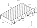
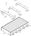
- FIG. 1 is a perspective view schematically showing a battery module 10 according to an embodiment of the present disclosure.
- FIG. 2 is an exploded perspective view schematically showing a state in which components of a battery module 10 according to an embodiment of the present disclosure are separated.
- a battery module 10 includes a cell assembly 100, a module tray 200, and a pair of side plates 300.
- the cell assembly 100 may include one or more battery cells.
- each battery cell may mean a secondary battery.
- a secondary battery may include an electrode assembly, an electrolyte, and a battery case.
- other types of the secondary battery such as a cylindrical battery or a prismatic battery, may also be employed in the cell assembly 100 of the present disclosure.
- the cell assembly 100 may be coupled to, for example, a bus bar frame assembly including a bus bar and a bus bar frame fixing the bus bar, and each of the battery cells included in the cell assembly 100 may be electrically connected by the bus bar.
- the module tray 200 may be configured to support the cell assembly 100. It is preferable that the module tray 200 is made of a material capable of absorbing impact so that the cell assembly 100 accommodated therein is not damaged during transportation.
- the pair of side plates 300 may be configured to cover one side and the other side (extension direction of the X-axis) of the cell assembly 100, respectively. At least one of the pair of side plates 300 includes a first sub-plate 300a and a second sub-plate 300b. The second sub-plate 300b overlaps and is coupled to the first sub-plate 300a.
- the first sub-plate 300a has a first flange portion 310a protruding outward, that is, in a direction opposite to the direction toward the cell assembly 100.
- the second sub-plate 300b has a second flange portion 310b protruding outward, that is, in a direction opposite to the direction toward the cell assembly 100.
- the second flange portion 310b is disposed to overlap the first flange portion 310a.
- the side plate 300 may be coupled to the module tray 200 substantially perpendicular thereto to cover the cell assembly 100.
- the first flange portion 310a protruding outward from the side plate 300 positioned substantially perpendicular to the module tray 200 and the second flange portion 310b disposed to overlap the first flange portion 310a may be used for fixing the battery module 10.
- the side plate 300 including the first sub-plate 300a and the second sub-plate 300b may have greater rigidity compared to the side plate 300 formed of a single member. Therefore, by applying such a side plate 300 structure, the rigidity of the battery module 10 itself may be improved, and on top of that, the swelling control of the battery cell may be effectively performed.
- the rigidity of the module flange 310 may be improved due to the overlapping structure of the first flange portion 310a and the second flange portion 310b.
- the rigidity of the fixing portion when the battery module 10 is fixed to a structure such as a pack tray, it is possible to secure the rigidity of the fixing portion.
- the module flange 310 of the side plate 300 may be configured to protrude in a direction away from the cell assembly 100 (in the X-axis direction) at a height 0.51 equal to half of the corresponding height or at a height lower than the height 0.51 equal to half thereof based on the height l of the cell assembly 100 (or the height of the side plate 300).
- the battery module 10 may include a front cover 210 and a rear cover 220 for covering both sides of the cell assembly 100 in the longitudinal direction (extension direction of the Y axis).
- the front cover 210 may cover the front of the cell assembly 100 (positive direction of the Y-axis), and the rear cover 220 may cover the rear of the cell assembly 100 (negative direction of the Y-axis).
- the front cover 210 and the rear cover 220 may be coupled to the module tray 200 substantially perpendicular thereto to cover the cell assembly 100.
- the front cover 210 and the rear cover 220 may also be coupled to the side plate 300 to cover the cell assembly 100.
- the front cover 210 and/or the rear cover 220 may also be integrally formed with the module tray 200.
- the battery module 10 may further include a thermal interface material (TIM) layer between the cell assembly 100 and the module tray 200 and/or between the cell assembly 100 and the front cover 210 and/or between the cell assembly 100 and the rear cover 220.
- the TIM layer may include various thermally conductive materials such as metal, polymer, or ceramic, and the TIM layer may be formed of a gel type or a phase change material.
- the module tray 200 and/or the front cover 210 and/or the rear cover 220 are made of a thermally conductive material and may serve as a heat sink for the corresponding battery module 10.
- the module tray 200 and/or the front cover 210 and/or the rear cover 220 may have a plurality of through holes A formed in a lattice shape.
- the plurality of through holes A may be filled with a thermal interface material (TIM) inside each through hole.
- the TIM may include various thermally conductive materials such as metal, polymer, or ceramic, and may be formed of a gel type or a phase change material.
- the battery module 10 and the battery pack 20 including the same may be further reduced in weight.
- the first flange portion 310a and the second flange portion 310b may have a flange hole H for fixing through a fixing member such as a pin or a bolt.
- a fixing member such as a pin or a bolt.
- the flange hole H is shown in a circular shape, but the present disclosure is not necessarily limited to such a shape and number of the flange hole H.
- FIG. 3 is a view showing an exemplary shape of a side plate 300 according to another embodiment of the present disclosure.
- At least one of the pair of side plates 300 may further include at least one third sub-plate 300c in addition to the first sub-plate 300a and the second sub-plate 300b.
- the third sub-plate 300c may overlap and be coupled to the first sub-plate 300a and the second sub-plate 300b.
- the third sub-plate 300c may include a third flange portion 310c disposed to overlap the first flange portion 310a and the second flange portion 310b.
- the at least one third sub-plate 300c may be interposed between the first sub-plate 300a and the second sub-plate 300b to constitute the side plate 300.
- the plurality of third flange portions 310c may be disposed to overlap each other, and may also be disposed to overlap the first flange portion 310a and the second flange portion 310b.
- the stiffness of the side plate 300 required in the design of the battery module 10 is insufficient due to the coupling of the first sub-plate 300a and the second sub-plate 300b, it is easy to produce the customized side plate 300 by adding the number of third sub-plates 300c according to the required stiffness.
- the first sub-plate 300a and the second sub-plate 300b may be coupled to each other by laser welding.
- various coupling methods such as bolting coupling, ultrasonic welding, and the like may be used.
- the first flange portion 310a and the second flange portion 310b may also be coupled by laser welding or the like. In this case, the rigidity of the flange portion may be further improved compared to the case where no separate coupling is performed.
- all the sub-plates 300a, 300b, 300c may be coupled to each other by laser welding or the like.
- all the flange portions 3 10a, 3 10b, 310c may also be coupled to each other by laser welding or the like.
- FIG. 4 is a view showing a changing state of an exemplary shape of a side plate 300 according to an embodiment of the present disclosure.
- the second sub-plate 300b may be positioned further outward than the first sub-plate 300a, and in this case, the first flange portion 310a may pass through the second sub-plate 300b and overlap the second flange portion 310b.
- the first flange portion 310a provided in the first sub-plate 300a may pass through the opening O formed in the second sub-plate 300b and be seated on the second flange portion 310b to overlap.
- the present disclosure is not limited to the shapes of the flange portions 310a, 310b shown in FIG. 4 and the specific opening O.
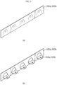
- FIG. 5 is a view showing an exemplary shape of sub-plates 300a, 300b according to an embodiment of the present disclosure.
- the second flange portion 310b may have a shape in which a portion of the second sub-plate 300b is cut and bent in a direction toward the outside of the second sub-plate 300b.
- the first flange portion 310a may be disposed to pass through the second sub-plate 300b through the opening O formed by cutting and bending the second sub-plate 300b and overlap the second flange portion 310b.
- the first flange portion 310a may have a shape in which a portion of the first sub-plate 300a is cut and bent in a direction toward the outside of the first sub-plate 300a.
- a portion of the sub-plates 300a, 300b is cut in the shape of the flange portions 310a, 310b by laser processing or press processing as shown in FIG. 5 (a) , and then the flange portions 310a, 310b may be formed by bending as shown in FIG. 5 (b) . Thereafter, as shown in FIG. 4 (a) , the first sub-plate 300a and the second sub-plate 300b may be coupled after the first flange portion 310a of the first sub-plate 300a passes through the second sub-plate 300b through the opening O formed by cutting and bending the second sub-plate 300b and is disposed to overlap the second flange portion 310b.
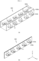
- FIG. 6 is a view showing a changing state of an exemplary shape of a side plate 300 according to still another embodiment of the present disclosure.
- the embodiment shown in FIG. 6 differs from the embodiments shown in FIGS. 4 and 5 in that the bending directions of the first flange portion 310a and the second flange portion 310b are opposite to each other, and the other matters are substantially the same. Therefore, in the following description, portions with differences will be mainly described, and overlapping descriptions will be omitted.
- the bending direction of the first flange portion 310a and the bending direction of the second flange portion 310b may be opposite to each other.
- a portion of the first sub-plate 300a may be cut and then bent upward to form the first flange portion 310a, as shown in FIG. 6 (a) .
- a portion of the second sub-plate 300b may be cut and then bent downward to form the second flange portion 310b.
- the first flange portion 310a may pass through the second sub-plate 300b and overlap the second flange portion 310b, as shown in FIG. 6 (b) .
- the present disclosure is not limited by these cutting and bending methods.
- a member bent in one direction is vulnerable to a force acting in a direction opposite to the bending direction, and thus may be easily deformed. Therefore, as described above, it is possible to complement each other by overlapping the first flange portion 310a and the second flange portion 310b formed by bending in opposite directions.
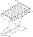
- FIG. 7 is a view showing an exemplary shape of a battery module 10 according to still another embodiment of the present disclosure.
- the battery module 10 may include a band member 400 coupled to a pair of side plates 300.
- the band member 400 may cover the cell assembly 100 without a separate module cover.
- the band member 400 may be disposed on top of the battery module 10.
- the band member 400 may be configured to support a pair of side plates 300, with one end in close contact with the side plate 300 covering one side of the cell assembly 100 and the other end in close contact with the side plate 300 covering the other side of the cell assembly 100.
- the battery module 10 may include one or two or more band members 300.
- the band member 400 may be made of a metal material having elasticity and rigidity.
- FIG. 8 is a view showing a band member included in the battery module of the present disclosure.
- the band member may include a support portion 410 and a pressing portion 420.
- the support portion 410 may be configured to have a predetermined width and extend to have a length corresponding to the distance between the pair of side plates.
- the pressing portion 420 may be configured to extend from both ends of the support portion 410 in the longitudinal direction and be in close contact with the corresponding side plate among the pair of side plates, respectively.
- the pressing portion 420 may be coupled to the corresponding side plate in various ways.
- the pressing portion 420 may be coupled to the corresponding side plate in a snap-fit manner, coupled using a separate fastening member, or coupled through welding, adhesion, or the like.
- FIG. 9 is a view showing an exemplary shape of a battery module according to still another embodiment of the present disclosure.
- the pressing portion 420 may be interposed between the first sub-plate 300a and the second sub-plate 300b.
- one side pressing portion 420 of the band member 400 may be positioned between the first sub-plate 300a and the second sub-plate 300b of the side plate 300 covering one side of the cell assembly 100 and coupled, and the other side pressing portion 420 thereof may be positioned between the first sub-plate 300a and the second sub-plate 300b of the side plate 300 covering the other side of the cell assembly 100 and coupled.
- the present disclosure is not limited to this arrangement and coupling method of the band member 400 and the side plate 300.
- the battery module 10 may further include an insulating sheet (not shown) interposed between the cell assembly 100 and the band member 400.
- the battery module 10 may further include a buffer pad (not shown) interposed between the cell assembly 100 and the band member 400 to prevent damage to the cell assembly 100 due to contact with the band member 400.
- FIG. 10 is a view showing an exemplary shape of a battery module according to still another embodiment of the present disclosure.
- the band member 400 may include a coupling portion 430.
- the coupling portion 430 extends from the pressing portion 420, and may be configured to extend toward the module flange 310 side of the corresponding side plate 300 with which the pressing portion 420 is in close contact to be coupled to a fixing portion 520 of a pack tray 500 to be described later, together with the module flange 310.
- the band member 400 may be interposed between the sub-plates 300a, 300b, thereby enabling more stable coupling compared to simply being interposed on the outer side of the side plate 300.
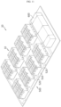
- FIG. 11 is a view showing an exemplary shape of a battery pack according to an embodiment of the present disclosure.
- the battery pack may include a pack tray 500 on which the battery module 10 is seated.
- the pack tray 500 may be formed of a metal material, a carbon material, a polymer synthetic resin, or a combination of two or more thereof having rigidity capable of supporting the corresponding battery modules 10 under the load of the battery modules 10.
- the pack tray 200 may include a seating portion 510 and a fixing portion 520.
- the seating portion 510 may be configured to have a seating surface on which the battery module 10 is seated.
- the seating portion 510 may be made of a thermally conductive metal material including Al.
- the fixing portion 520 may protrude from the upper surface of the pack tray 500 to a predetermined height.
- the fixing portion 520 may be configured to protrude to a predetermined height from each of both sides of the seating surface on which the battery module 10 is seated and have a step with the corresponding seating surface.
- the fixing portion 520 may protrude to a height lower than the height of the battery module 10 seated on the corresponding seating surface.
- the fixing portion 520 may protrude to a height lower than half of the height of the battery module 10 seated on the corresponding seating surface.
- the fixing portion 520 may be made of a metal material including Al.
- the fixing portion 520 may be configured in the form of an extended square beam or square pipe with a certain width and thickness and coupled to the seating portion 510.
- the fixing portion 520 may have a hollow tube structure.
- the seating portion 510 and the fixing portion 520 of the pack tray 500 may be integrally formed.
- the pack tray 500 is manufactured integrally by applying a casting, sheet metal, or press process to a plastic material, and may be manufactured such that a relatively concave seating portion 510 and a relatively convex fixing portion 520 are formed alternately and repeatedly in one direction on the bottom surface thereof.
- the fixing portion 520 may be coupled to the module flanges 310 protruding from each of the side plates 300 on both sides of the battery module 10 seated on the seating surface of the seating portion 510, thereby fixing the battery module 10.
- the fixing portion 520 may be coupled respectively to the battery module 10 on both sides of the battery module 10 to fix the corresponding battery module 10, thereby mitigating the corresponding impact even when an impact is applied to the battery pack 20, resulting in protecting the battery module 10 disposed inside the battery pack 20.
- the free space secured at the top of the fixing portion 520 may prevent collision between the battery modules 10 even if structural deformation occurs in the battery pack 20, thereby minimizing damage to the battery cells constituting each battery module 10.
- the electric unit 600 may include various electronic components that control the charge/discharge operation of the battery modules accommodated in the pack tray 500 or monitor the state of charge (SOC), the state of health (SOH) and the like of each battery module or the battery cells constituting each battery module, and may be accommodated and fixed in the pack tray 500 together with the battery modules.
- SOC state of charge
- SOH state of health
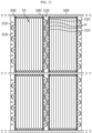
- FIG. 12 is a view showing an exemplary shape of a battery pack according to another embodiment of the present disclosure.
- the battery pack may include a pack tray 500 on which the battery module 10 is seated.
- a fixing portion 520 protruding to a predetermined height may be provided on the upper surface of the pack tray 500.
- the battery module 10 may be coupled to the fixing portion 520 through the module flange 310 formed by overlapping the first flange portion 310a and the second flange portion 310b.
- the module flange 310 and the fixing portion 520 may be coupled to the flange hole H through a fastening member such as a pin, a bolt, or the like.
- the module flanges 310 of the side plate 300 on one side may be located between the module flanges 310 of the side plate 300 on the other side.
- energy density may be increased by increasing space efficiency in a secondary battery where energy density is important.
- the battery pack 20 may include one or more battery modules 10 according to the present disclosure described above. Also, the battery pack 20 according to the present disclosure may further include other various components in addition to the battery module 10, for example, components of the battery pack known at the time of filing of the present disclosure, such as a BMS, bus bar, pack case, relay, current sensor, and the like.
- FIG. 13 is a view schematically showing a vehicle including a battery module according to an embodiment of the present disclosure.
- a vehicle 30 according to an embodiment of the present disclosure may include one or more battery modules 10 according to the present disclosure described above. Also, the vehicle 30 according to the present disclosure may further include other various components included in the vehicle 30 in addition to the battery module 10 or the battery pack 20. For example, the vehicle 30 according to the present disclosure may further include a vehicle body, a motor, and a control device such as an electronic control unit (ECU), and the like, in addition to the battery module according to the present disclosure.
- ECU electronice control unit
Landscapes
- Chemical & Material Sciences (AREA)
- Chemical Kinetics & Catalysis (AREA)
- Electrochemistry (AREA)
- General Chemical & Material Sciences (AREA)
- Engineering & Computer Science (AREA)
- Aviation & Aerospace Engineering (AREA)
- Battery Mounting, Suspending (AREA)
Abstract
Description
- The present disclosure relates to a battery module, and a battery pack and a vehicle including the same, and more specifically, to a battery module having a side plate with a flange portion for connection of the battery module on the side of the battery module, and a battery pack and a vehicle including the same. The present application claims priority to
Korean Patent Application No. 10-2022-0065674 filed on May 27, 2022 Korean Patent Application No. 10-2022-0064703 filed on May 26, 2022 - Secondary batteries have high applicability according to product groups and electrical characteristics such as high energy density, and thus are commonly applied not only to portable devices but also to electric vehicles (EVs) or hybrid electric vehicles (HEVs) driven by electric power sources. Such secondary batteries are attracting attention as a new energy source to improve eco-friendliness and energy efficiency in that they have not only a primary advantage of dramatically reducing the use of fossil fuels, but also no by-products generated from the use of energy.
- Secondary batteries widely used at present include lithium-ion batteries, lithium polymer batteries, nickel cadmium batteries, nickel hydrogen batteries, nickel zinc batteries and the like. An operating voltage of the unit secondary battery cell, namely a unit battery cell, is about 2.5 V to 4.5 V. Therefore, if a higher output voltage is required, a plurality of battery cells may be connected in series to configure a battery pack. In addition, depending on the charge/discharge capacity required for the battery pack, a plurality of battery cells may be connected in parallel to configure a battery pack. Thus, the number of battery cells included in the battery pack may be variously set according to the required output voltage or the demanded charge/discharge capacity.
- Meanwhile, when a plurality of battery cells are connected in series/parallel to configure a battery pack, it is common to first configure a battery module including at least one battery cell and then use this at least one battery module to configure a battery pack by adding other components. Among them, a side plate covering the battery cell from the side plays a role of controlling the swelling of the battery cell and fixing the module, thereby having the most complicated shape among other components and being necessarily obliged to satisfy the required rigidity. Therefore, it is preferable to configure a battery module including a side plate capable of satisfying rigidity required for easier manufacturing.
- The present disclosure is designed to solve the problems of the related art, and therefore the present disclosure is directed to providing a battery module including a side plate that is easy to manufacture and easily satisfies the required rigidity.
- Other objects and advantages of the present disclosure may be understood from the following description and will be more clearly understood by the embodiments of the present disclosure. Also, it will be easily understood that the objects and advantages of the present disclosure may be realized by the means shown in the appended claims and combinations thereof.
- A battery module according to one aspect of the present disclosure for achieving the above-described object includes a cell assembly having a plurality of battery cells; a module tray configured to support the cell assembly; and a pair of side plates configured to cover one side and the other side of the cell assembly, respectively, wherein at least one of the pair of side plates includes a first sub-plate having a first flange portion protruding outward; and a second sub-plate that has a second flange portion protruding outward and disposed to overlap the first flange portion and is coupled by overlapping the first sub-plate.
- At least one of the pair of side plates further includes at least one third sub-plate that is coupled by overlapping the first sub-plate and the second sub-plate and has a third flange portion disposed to overlap the first flange portion and the second flange portion.
- In at least one of the pair of side plates, the first sub-plate and the second sub-plate are coupled to each other by laser welding.
- The second sub-plate is located further outward than the first sub-plate, and the first flange portion passes through the second sub-plate and overlaps the second flange portion.
- The second flange portion has a shape in which a portion of the second sub-plate is cut and bent in a direction toward the outside of the second sub-plate.
- The first flange portion passes through the second sub-plate through an opening formed by cutting and bending the second sub-plate and is disposed to overlap the second flange portion.
- The first flange portion has a shape in which a portion of the first sub-plate is cut and bent in a direction toward the outside of the first sub-plate.
- A bending direction of the first flange portion and a bending direction of the second flange portion may be opposite to each other.
- The battery module includes a band member coupled to the pair of side plates.
- The band member is disposed on top of the battery module.
- At least one end of both ends of the band member is interposed between the first sub-plate and the second sub-plate.
- A battery pack according to the present disclosure includes a battery module according to the present disclosure.
- A vehicle according to the present disclosure includes a battery module according to the present disclosure.
- According to one aspect of the present disclosure, it is possible to ensure more excellent rigidity so as to cover the cell assembly and fix the module effectively compared to the side plate made of a single member. Therefore, effective cell swelling control and module fixing are possible.
- According to another aspect of the present disclosure, without the need to couple a separate member corresponding to the flange portion for fixing the battery module to the side plate, the flange portion has a shape in which a portion of the side plate is cut and bent. Therefore, in a secondary battery where energy density is important, energy density may be increased by reducing the weight of the flange portion member, a separate bonding process for the flange portion member may be omitted, and only a sub-plate having the same shape needs to be produced, thereby facilitating manufacturing and increasing production efficiency.
- According to still another aspect of the present disclosure, a single bent portion may be vulnerable to stress in a bending direction and in the opposite direction due to bending, but this may be supplemented to each other by coupling.
- According to still another aspect of the present disclosure, the cell assembly may be covered without a separate module cover through the band member.
- According to still another aspect of the present disclosure, the band member is interposed between the sub-plates, thereby enabling more stable coupling compared to being simply interposed outside of the side plate.
- In addition, several other additional effects may be achieved by various embodiments of the present disclosure. These various effects of the present disclosure will be described in detail in each embodiment, or descriptions of effects that may be easily understood by those skilled in the art will be omitted.
- The accompanying drawings illustrate a preferred embodiment of the present disclosure and together with the foregoing disclosure, serve to provide further understanding of the technical features of the present disclosure, and thus the present disclosure is not construed as being limited to the drawing.
-
FIG. 1 is a perspective view showing the appearance of a battery module according to an embodiment of the present disclosure. -
FIG. 2 is an exploded perspective view showing a battery module according to an embodiment of the present disclosure. -
FIG. 3 is a view showing an exemplary shape of a side plate according to another embodiment of the present disclosure. -
FIG. 4 is a view showing a changing state of an exemplary shape of a side plate according to an embodiment of the present disclosure. -
FIG. 5 is a view showing a changing state of an exemplary shape of a sub-plate according to an embodiment of the present disclosure. -
FIG. 6 is a view showing a changing state of an exemplary shape of a side plate according to still another embodiment of the present disclosure. -
FIG. 7 is a view showing an exemplary shape of a battery module according to still another embodiment of the present disclosure. -
FIG. 8 is a view showing a band member included in the battery module of the present disclosure. -
FIG. 9 is a view showing an exemplary shape of a battery module according to still another embodiment of the present disclosure. -
FIG. 10 is a view showing an exemplary shape of a battery module according to still another embodiment of the present disclosure. -
FIG. 11 is a view showing an exemplary shape of a battery pack according to an embodiment of the present disclosure. -
FIG. 12 is a view showing an exemplary shape of a battery pack according to another embodiment of the present disclosure. -
FIG. 13 is a view schematically showing a vehicle including a battery module according to an embodiment of the present disclosure. - The present disclosure will become more apparent by describing preferred embodiments of the present disclosure in detail with reference to the accompanying drawings. The embodiments described herein are shown by way of example to help understanding of the present disclosure, and it should be understood that the present disclosure may be variously modified and implemented differently from the embodiments described herein. In addition, to help understanding of the present disclosure, the accompanying drawings are not illustrated on an actual scale, but the dimensions of some components may be exaggerated.
- Although the preferred embodiments of the present disclosure have been shown and described above, the present disclosure is not limited to the above-described specific embodiments, and it is a matter of course that various modifications may be implemented by those who skilled in the art to which the present disclosure appertains without departing from the gist of the present disclosure claimed in the claims, wherein these modifications should not be individually understood from the technical idea or prospect of the present disclosure.
-
FIG. 1 is a perspective view schematically showing abattery module 10 according to an embodiment of the present disclosure. And,FIG. 2 is an exploded perspective view schematically showing a state in which components of abattery module 10 according to an embodiment of the present disclosure are separated. - Referring to
FIGS. 1 and2 , abattery module 10 according to an embodiment of the present disclosure includes acell assembly 100, amodule tray 200, and a pair ofside plates 300. - Specifically, the
cell assembly 100 may include one or more battery cells. Here, each battery cell may mean a secondary battery. A secondary battery may include an electrode assembly, an electrolyte, and a battery case. However, other types of the secondary battery, such as a cylindrical battery or a prismatic battery, may also be employed in thecell assembly 100 of the present disclosure. Thecell assembly 100 may be coupled to, for example, a bus bar frame assembly including a bus bar and a bus bar frame fixing the bus bar, and each of the battery cells included in thecell assembly 100 may be electrically connected by the bus bar. - The
module tray 200 may be configured to support thecell assembly 100. It is preferable that themodule tray 200 is made of a material capable of absorbing impact so that thecell assembly 100 accommodated therein is not damaged during transportation. - The pair of
side plates 300 may be configured to cover one side and the other side (extension direction of the X-axis) of thecell assembly 100, respectively. At least one of the pair ofside plates 300 includes a first sub-plate 300a and a second sub-plate 300b. The second sub-plate 300b overlaps and is coupled to the first sub-plate 300a. The first sub-plate 300a has afirst flange portion 310a protruding outward, that is, in a direction opposite to the direction toward thecell assembly 100. The second sub-plate 300b has asecond flange portion 310b protruding outward, that is, in a direction opposite to the direction toward thecell assembly 100. Thesecond flange portion 310b is disposed to overlap thefirst flange portion 310a. - The
side plate 300 may be coupled to themodule tray 200 substantially perpendicular thereto to cover thecell assembly 100. Thefirst flange portion 310a protruding outward from theside plate 300 positioned substantially perpendicular to themodule tray 200 and thesecond flange portion 310b disposed to overlap thefirst flange portion 310a may be used for fixing thebattery module 10. As such, theside plate 300 including the first sub-plate 300a and the second sub-plate 300b may have greater rigidity compared to theside plate 300 formed of a single member. Therefore, by applying such aside plate 300 structure, the rigidity of thebattery module 10 itself may be improved, and on top of that, the swelling control of the battery cell may be effectively performed. In addition, according to the above-described embodiment, the rigidity of the module flange 310 (seeFIG. 12 ) may be improved due to the overlapping structure of thefirst flange portion 310a and thesecond flange portion 310b. Thus, when thebattery module 10 is fixed to a structure such as a pack tray, it is possible to secure the rigidity of the fixing portion. - The
module flange 310 of theside plate 300 may be configured to protrude in a direction away from the cell assembly 100 (in the X-axis direction) at a height 0.51 equal to half of the corresponding height or at a height lower than the height 0.51 equal to half thereof based on the height l of the cell assembly 100 (or the height of the side plate 300). - Referring to
FIGS. 1 and2 , thebattery module 10 may include afront cover 210 and arear cover 220 for covering both sides of thecell assembly 100 in the longitudinal direction (extension direction of the Y axis). Thefront cover 210 may cover the front of the cell assembly 100 (positive direction of the Y-axis), and therear cover 220 may cover the rear of the cell assembly 100 (negative direction of the Y-axis). Thefront cover 210 and therear cover 220 may be coupled to themodule tray 200 substantially perpendicular thereto to cover thecell assembly 100. In addition, thefront cover 210 and therear cover 220 may also be coupled to theside plate 300 to cover thecell assembly 100. Meanwhile, thefront cover 210 and/or therear cover 220 may also be integrally formed with themodule tray 200. - Meanwhile, the
battery module 10 may further include a thermal interface material (TIM) layer between thecell assembly 100 and themodule tray 200 and/or between thecell assembly 100 and thefront cover 210 and/or between thecell assembly 100 and therear cover 220. The TIM layer may include various thermally conductive materials such as metal, polymer, or ceramic, and the TIM layer may be formed of a gel type or a phase change material. - In this case, the
module tray 200 and/or thefront cover 210 and/or therear cover 220 are made of a thermally conductive material and may serve as a heat sink for thecorresponding battery module 10. - In particular, the
module tray 200 and/or thefront cover 210 and/or therear cover 220 may have a plurality of through holes A formed in a lattice shape. In this case, the plurality of through holes A may be filled with a thermal interface material (TIM) inside each through hole. The TIM may include various thermally conductive materials such as metal, polymer, or ceramic, and may be formed of a gel type or a phase change material. - As such, by applying the
module tray 200 and/or thefront cover 210 and/or therear cover 220 having a lattice structure to thebattery module 10, thebattery module 10 and thebattery pack 20 including the same may be further reduced in weight. - The
first flange portion 310a and thesecond flange portion 310b may have a flange hole H for fixing through a fixing member such as a pin or a bolt. InFIG. 1 , the flange hole H is shown in a circular shape, but the present disclosure is not necessarily limited to such a shape and number of the flange hole H. -
FIG. 3 is a view showing an exemplary shape of aside plate 300 according to another embodiment of the present disclosure. - Referring to
FIG. 3 , at least one of the pair ofside plates 300 may further include at least one third sub-plate 300c in addition to the first sub-plate 300a and the second sub-plate 300b. The third sub-plate 300c may overlap and be coupled to the first sub-plate 300a and the second sub-plate 300b. The third sub-plate 300c may include athird flange portion 310c disposed to overlap thefirst flange portion 310a and thesecond flange portion 310b. The at least one third sub-plate 300c may be interposed between the first sub-plate 300a and the second sub-plate 300b to constitute theside plate 300. When a plurality of third sub-plates 300c are provided, the plurality ofthird flange portions 310c may be disposed to overlap each other, and may also be disposed to overlap thefirst flange portion 310a and thesecond flange portion 310b. - According to this embodiment of the present disclosure, when the stiffness of the
side plate 300 required in the design of thebattery module 10 is insufficient due to the coupling of the first sub-plate 300a and the second sub-plate 300b, it is easy to produce the customizedside plate 300 by adding the number of third sub-plates 300c according to the required stiffness. - In at least one of the pair of
side plates 300, the first sub-plate 300a and the second sub-plate 300b may be coupled to each other by laser welding. In the present disclosure, as a coupling method between components, not only laser welding, but also various coupling methods such as bolting coupling, ultrasonic welding, and the like may be used. In this case, compared to the case where no separate coupling is performed, it is possible to secure more excellent rigidity to control battery cell swelling and fix the module effectively through the coupling. Thefirst flange portion 310a and thesecond flange portion 310b may also be coupled by laser welding or the like. In this case, the rigidity of the flange portion may be further improved compared to the case where no separate coupling is performed. - Meanwhile, when at least one of the pair of
side plates 300 further includes at least one third sub-plate 300c in addition to the first sub-plate 300a and the second sub-plate 300b, all the sub-plates 300a, 300b, 300c may be coupled to each other by laser welding or the like. Similarly, all the flange portions 3 10a, 3 10b, 310c may also be coupled to each other by laser welding or the like. -
FIG. 4 is a view showing a changing state of an exemplary shape of aside plate 300 according to an embodiment of the present disclosure. - Referring to
FIG. 4 , the second sub-plate 300b may be positioned further outward than the first sub-plate 300a, and in this case, thefirst flange portion 310a may pass through the second sub-plate 300b and overlap thesecond flange portion 310b. For example, thefirst flange portion 310a provided in the first sub-plate 300a may pass through the opening O formed in the second sub-plate 300b and be seated on thesecond flange portion 310b to overlap. However, the present disclosure is not limited to the shapes of theflange portions FIG. 4 and the specific opening O. -
FIG. 5 is a view showing an exemplary shape of sub-plates 300a, 300b according to an embodiment of the present disclosure. - Referring to
FIGS. 4 and5 , thesecond flange portion 310b may have a shape in which a portion of the second sub-plate 300b is cut and bent in a direction toward the outside of the second sub-plate 300b. Thefirst flange portion 310a may be disposed to pass through the second sub-plate 300b through the opening O formed by cutting and bending the second sub-plate 300b and overlap thesecond flange portion 310b. Thefirst flange portion 310a may have a shape in which a portion of the first sub-plate 300a is cut and bent in a direction toward the outside of the first sub-plate 300a. For example, a portion of the sub-plates 300a, 300b is cut in the shape of theflange portions FIG. 5 (a) , and then theflange portions FIG. 5 (b) . Thereafter, as shown inFIG. 4 (a) , the first sub-plate 300a and the second sub-plate 300b may be coupled after thefirst flange portion 310a of the first sub-plate 300a passes through the second sub-plate 300b through the opening O formed by cutting and bending the second sub-plate 300b and is disposed to overlap thesecond flange portion 310b. In this case, for smooth coupling between the first sub-plate 300a and the second sub-plate 300b and for accurate overlapping of thefirst flange portion 310a and thesecond flange portion 310b, the cut length in the height direction (extension direction of the Z-axis) for forming thefirst flange portion 310a may be longer than the cut length in the height direction (extension direction of the Z-axis) for forming thesecond flange portion 310b by approximately the thickness of the second sub-plate 300b. In this case, the flange holes H formed in each of thefirst flange portion 310a and thesecond flange portion 310b may exactly overlap each other. However, the present disclosure is not limited by these cutting and bending methods. - According to this configuration of the present disclosure, there is no need to couple a separate member corresponding to the
flange portions battery module 10 to theside plate 300. Therefore, manufacturing of the battery module is facilitated, and production efficiency may be increased. -
FIG. 6 is a view showing a changing state of an exemplary shape of aside plate 300 according to still another embodiment of the present disclosure. The embodiment shown inFIG. 6 differs from the embodiments shown inFIGS. 4 and5 in that the bending directions of thefirst flange portion 310a and thesecond flange portion 310b are opposite to each other, and the other matters are substantially the same. Therefore, in the following description, portions with differences will be mainly described, and overlapping descriptions will be omitted. - Referring to
FIG. 6 , the bending direction of thefirst flange portion 310a and the bending direction of thesecond flange portion 310b may be opposite to each other. For example, referring toFIG. 6 , a portion of the first sub-plate 300a may be cut and then bent upward to form thefirst flange portion 310a, as shown inFIG. 6 (a) . Similarly, a portion of the second sub-plate 300b may be cut and then bent downward to form thesecond flange portion 310b. Thefirst flange portion 310a may pass through the second sub-plate 300b and overlap thesecond flange portion 310b, as shown inFIG. 6 (b) . However, the present disclosure is not limited by these cutting and bending methods. - A member bent in one direction is vulnerable to a force acting in a direction opposite to the bending direction, and thus may be easily deformed. Therefore, as described above, it is possible to complement each other by overlapping the
first flange portion 310a and thesecond flange portion 310b formed by bending in opposite directions. -
FIG. 7 is a view showing an exemplary shape of abattery module 10 according to still another embodiment of the present disclosure. - Referring to
FIG. 7 , thebattery module 10 may include aband member 400 coupled to a pair ofside plates 300. In this case, theband member 400 may cover thecell assembly 100 without a separate module cover. For example, theband member 400 may be disposed on top of thebattery module 10. - The
band member 400 may be configured to support a pair ofside plates 300, with one end in close contact with theside plate 300 covering one side of thecell assembly 100 and the other end in close contact with theside plate 300 covering the other side of thecell assembly 100. To this end, thebattery module 10 may include one or two ormore band members 300. - The
band member 400 may be made of a metal material having elasticity and rigidity. -
FIG. 8 is a view showing a band member included in the battery module of the present disclosure. - Referring to
FIG. 8 , the band member may include asupport portion 410 and apressing portion 420. - The
support portion 410 may be configured to have a predetermined width and extend to have a length corresponding to the distance between the pair of side plates. - The
pressing portion 420 may be configured to extend from both ends of thesupport portion 410 in the longitudinal direction and be in close contact with the corresponding side plate among the pair of side plates, respectively. In this case, thepressing portion 420 may be coupled to the corresponding side plate in various ways. For example, thepressing portion 420 may be coupled to the corresponding side plate in a snap-fit manner, coupled using a separate fastening member, or coupled through welding, adhesion, or the like. -
FIG. 9 is a view showing an exemplary shape of a battery module according to still another embodiment of the present disclosure. - Referring to
FIG. 9 , thepressing portion 420 may be interposed between the first sub-plate 300a and the second sub-plate 300b. For example, oneside pressing portion 420 of theband member 400 may be positioned between the first sub-plate 300a and the second sub-plate 300b of theside plate 300 covering one side of thecell assembly 100 and coupled, and the other sidepressing portion 420 thereof may be positioned between the first sub-plate 300a and the second sub-plate 300b of theside plate 300 covering the other side of thecell assembly 100 and coupled. However, the present disclosure is not limited to this arrangement and coupling method of theband member 400 and theside plate 300. - The
battery module 10 may further include an insulating sheet (not shown) interposed between thecell assembly 100 and theband member 400. In another embodiment, thebattery module 10 may further include a buffer pad (not shown) interposed between thecell assembly 100 and theband member 400 to prevent damage to thecell assembly 100 due to contact with theband member 400. -
FIG. 10 is a view showing an exemplary shape of a battery module according to still another embodiment of the present disclosure. - Referring to
FIG. 10 , theband member 400 may include acoupling portion 430. - The
coupling portion 430 extends from thepressing portion 420, and may be configured to extend toward themodule flange 310 side of thecorresponding side plate 300 with which thepressing portion 420 is in close contact to be coupled to a fixingportion 520 of apack tray 500 to be described later, together with themodule flange 310. According to this configuration of the present disclosure, theband member 400 may be interposed between the sub-plates 300a, 300b, thereby enabling more stable coupling compared to simply being interposed on the outer side of theside plate 300. -
FIG. 11 is a view showing an exemplary shape of a battery pack according to an embodiment of the present disclosure. - Referring to
FIG. 11 , the battery pack may include apack tray 500 on which thebattery module 10 is seated. - The
pack tray 500 may be formed of a metal material, a carbon material, a polymer synthetic resin, or a combination of two or more thereof having rigidity capable of supporting the correspondingbattery modules 10 under the load of thebattery modules 10. - The
pack tray 200 may include aseating portion 510 and a fixingportion 520. - The
seating portion 510 may be configured to have a seating surface on which thebattery module 10 is seated. Theseating portion 510 may be made of a thermally conductive metal material including Al. - The fixing
portion 520 may protrude from the upper surface of thepack tray 500 to a predetermined height. The fixingportion 520 may be configured to protrude to a predetermined height from each of both sides of the seating surface on which thebattery module 10 is seated and have a step with the corresponding seating surface. The fixingportion 520 may protrude to a height lower than the height of thebattery module 10 seated on the corresponding seating surface. The fixingportion 520 may protrude to a height lower than half of the height of thebattery module 10 seated on the corresponding seating surface. The fixingportion 520 may be made of a metal material including Al. - The fixing
portion 520 may be configured in the form of an extended square beam or square pipe with a certain width and thickness and coupled to theseating portion 510. The fixingportion 520 may have a hollow tube structure. - The
seating portion 510 and the fixingportion 520 of thepack tray 500 may be integrally formed. Thepack tray 500 is manufactured integrally by applying a casting, sheet metal, or press process to a plastic material, and may be manufactured such that a relativelyconcave seating portion 510 and a relativelyconvex fixing portion 520 are formed alternately and repeatedly in one direction on the bottom surface thereof. - The fixing
portion 520 may be coupled to themodule flanges 310 protruding from each of theside plates 300 on both sides of thebattery module 10 seated on the seating surface of theseating portion 510, thereby fixing thebattery module 10. - The fixing
portion 520 may be coupled respectively to thebattery module 10 on both sides of thebattery module 10 to fix thecorresponding battery module 10, thereby mitigating the corresponding impact even when an impact is applied to thebattery pack 20, resulting in protecting thebattery module 10 disposed inside thebattery pack 20. - The free space secured at the top of the fixing
portion 520 may prevent collision between thebattery modules 10 even if structural deformation occurs in thebattery pack 20, thereby minimizing damage to the battery cells constituting eachbattery module 10. - The
electric unit 600 may include various electronic components that control the charge/discharge operation of the battery modules accommodated in thepack tray 500 or monitor the state of charge (SOC), the state of health (SOH) and the like of each battery module or the battery cells constituting each battery module, and may be accommodated and fixed in thepack tray 500 together with the battery modules. -
FIG. 12 is a view showing an exemplary shape of a battery pack according to another embodiment of the present disclosure. - Referring to
FIG. 12 , the battery pack may include apack tray 500 on which thebattery module 10 is seated. A fixingportion 520 protruding to a predetermined height may be provided on the upper surface of thepack tray 500. Thebattery module 10 may be coupled to the fixingportion 520 through themodule flange 310 formed by overlapping thefirst flange portion 310a and thesecond flange portion 310b. Themodule flange 310 and the fixingportion 520 may be coupled to the flange hole H through a fastening member such as a pin, a bolt, or the like. By making a difference in the number and position of themodule flanges 310 of theside plates 300 on both sides of thebattery module 10, themodule flanges 310 of theside plate 300 on one side may be located between themodule flanges 310 of theside plate 300 on the other side. In this case, energy density may be increased by increasing space efficiency in a secondary battery where energy density is important. - Referring to
FIG. 12 , thebattery pack 20 according to an embodiment of the present disclosure may include one ormore battery modules 10 according to the present disclosure described above. Also, thebattery pack 20 according to the present disclosure may further include other various components in addition to thebattery module 10, for example, components of the battery pack known at the time of filing of the present disclosure, such as a BMS, bus bar, pack case, relay, current sensor, and the like. -
FIG. 13 is a view schematically showing a vehicle including a battery module according to an embodiment of the present disclosure. - Referring to
FIG. 13 , avehicle 30 according to an embodiment of the present disclosure may include one ormore battery modules 10 according to the present disclosure described above. Also, thevehicle 30 according to the present disclosure may further include other various components included in thevehicle 30 in addition to thebattery module 10 or thebattery pack 20. For example, thevehicle 30 according to the present disclosure may further include a vehicle body, a motor, and a control device such as an electronic control unit (ECU), and the like, in addition to the battery module according to the present disclosure. - As described above, the present disclosure has been described mainly with preferred embodiments with reference to the accompanying drawings, but it is apparent to those skilled in the art that many and various obvious modifications are possible from this description without departing from the scope of the present disclosure. Therefore, the scope of the present disclosure should be construed by the claims which are written to include examples of such many modifications.
-
- battery module (10)
- battery pack (20)
- vehicle (30)
- cell assembly (100)
- module tray (200)
- front cover (210)
- rear cover (220)
- through hole (A)
- side plate (300)
- first sub-plate (300a)
- second sub-plate (300b)
- third sub-plate (300c)
- module flange (310)
- first flange portion (310a)
- second flange portion (310b)
- third flange portion (310c)
- band member (400)
- support portion (410)
- pressing portion (420)
- coupling portion (430)
- pack tray (500)
- seating portion (510)
- fixing portion (520)
- electric unit (600)
- flange hole (H)
- opening (O)
Claims (15)
- A battery module, comprising:a cell assembly having a plurality of battery cells;a module tray configured to support the cell assembly; anda pair of side plates configured to cover one side and the other side of the cell assembly, respectively,wherein at least one of the pair of side plates comprises:a first sub-plate having a first flange portion protruding outward; anda second sub-plate having a second flange portion protruding outward and disposed to overlap the first flange portion and is coupled by overlapping the first sub-plate.
- The battery module according to claim 1,
wherein the at least one of the pair of side plates further comprises at least one third sub-plate that is coupled by overlapping the first sub-plate and the second sub-plate and has a third flange portion disposed to overlap the first flange portion and the second flange portion. - The battery module according to claim 1,
wherein in the at least one of the pair of side plates, the first sub-plate and the second sub-plate are coupled to each other by laser welding. - The battery module according to claim 1,
wherein the second sub-plate is located further outward than the first sub-plate, and the first flange portion passes through the second sub-plate and overlaps with the second flange portion. - The battery module according to claim 4,
wherein the second flange portion has a shape in which a portion of the second sub-plate is cut and bent in a direction toward the outside of the second sub-plate. - The battery module according to claim 5,
wherein the first flange portion passes through the second sub-plate through an opening formed by cutting and bending the second sub-plate and is disposed to overlap the second flange portion. - The battery module according to claim 5,
wherein the first flange portion has a shape in which a portion of the first sub-plate is cut and bent in a direction toward the outside of the first sub-plate. - The battery module according to claim 7,
wherein a bending direction of the first flange portion and a bending direction of the second flange portion are opposite to each other. - The battery module according to claim 1, further comprising:
a band member coupled to the pair of side plates. - The battery module according to claim 9,
wherein the band member is disposed on top of the battery module. - The battery module according to claim 10,
wherein at least one end of both ends of the band member is interposed between the first sub-plate and the second sub-plate. - A battery pack, comprising:
at least one battery module according to any one of claims 1 to 11. - The battery pack according to claim 12, further comprising:
a pack tray on which the at least one battery module is seated. - The battery pack according to claim 13, further comprising:a mounting beam protruding to a predetermined height provided on an upper surface of the pack tray,wherein the battery module is coupled to the mounting beam through a module flange formed by overlapping the first flange portion and the second flange portion.
- A vehicle, comprising:
at least one battery pack according to claim 12.
Applications Claiming Priority (3)
| Application Number | Priority Date | Filing Date | Title |
|---|---|---|---|
| KR20220064703 | 2022-05-26 | ||
| KR20220065674 | 2022-05-27 | ||
| PCT/KR2023/007330 WO2023229444A1 (en) | 2022-05-26 | 2023-05-26 | Battery module, and battery pack and vehicle comprising the battery module |
Publications (3)
| Publication Number | Publication Date |
|---|---|
| EP4465429A1 true EP4465429A1 (en) | 2024-11-20 |
| EP4465429A4 EP4465429A4 (en) | 2025-05-07 |
| EP4465429B1 EP4465429B1 (en) | 2026-04-08 |
Family
ID=88919825
Family Applications (1)
| Application Number | Title | Priority Date | Filing Date |
|---|---|---|---|
| EP23812218.8A Active EP4465429B1 (en) | 2022-05-26 | 2023-05-26 | Battery module, and battery pack and vehicle including the same |
Country Status (5)
| Country | Link |
|---|---|
| US (1) | US20250309434A1 (en) |
| EP (1) | EP4465429B1 (en) |
| JP (1) | JP7753555B2 (en) |
| KR (1) | KR20230165155A (en) |
| WO (1) | WO2023229444A1 (en) |
Families Citing this family (3)
| Publication number | Priority date | Publication date | Assignee | Title |
|---|---|---|---|---|
| KR20250158416A (en) | 2024-04-30 | 2025-11-06 | 주식회사 엘지에너지솔루션 | Battery pack |
| KR20250176471A (en) * | 2024-06-12 | 2025-12-19 | 주식회사 엘지에너지솔루션 | Battery pack and vehicle including the same |
| KR20260022093A (en) * | 2024-08-07 | 2026-02-19 | 주식회사 엘지에너지솔루션 | Battery pack and method of manufaturing the same |
Family Cites Families (7)
| Publication number | Priority date | Publication date | Assignee | Title |
|---|---|---|---|---|
| KR100919390B1 (en) * | 2006-02-13 | 2009-09-29 | 주식회사 엘지화학 | Medium and Large Size Battery Module of Vertical Stacking Structure |
| KR101913866B1 (en) * | 2012-12-27 | 2018-12-28 | 에스케이이노베이션 주식회사 | Secondary Battery Module |
| KR20200111988A (en) * | 2019-03-20 | 2020-10-05 | 주식회사 성우하이텍 | Manufacturing method of battery module case for electric vehicle |
| WO2021024775A1 (en) | 2019-08-03 | 2021-02-11 | 三洋電機株式会社 | Power supply device, and electric vehicle and power storage device equipped with this power supply device |
| KR102410520B1 (en) * | 2020-08-20 | 2022-06-20 | 현대자동차주식회사 | Structure for mounting battery on body |
| KR20220064703A (en) | 2020-11-12 | 2022-05-19 | 김정의 | Tray with cotton fablic |
| EP4002017B1 (en) | 2020-11-13 | 2026-02-25 | Comadur S.A. | Anti-corrosion protection for timepiece magnets, in particular neodymium-iron-boron |
-
2023
- 2023-05-26 US US18/863,329 patent/US20250309434A1/en active Pending
- 2023-05-26 JP JP2024541066A patent/JP7753555B2/en active Active
- 2023-05-26 EP EP23812218.8A patent/EP4465429B1/en active Active
- 2023-05-26 WO PCT/KR2023/007330 patent/WO2023229444A1/en not_active Ceased
- 2023-05-26 KR KR1020230068710A patent/KR20230165155A/en active Pending
Also Published As
| Publication number | Publication date |
|---|---|
| US20250309434A1 (en) | 2025-10-02 |
| WO2023229444A1 (en) | 2023-11-30 |
| JP7753555B2 (en) | 2025-10-14 |
| KR20230165155A (en) | 2023-12-05 |
| EP4465429B1 (en) | 2026-04-08 |
| EP4465429A4 (en) | 2025-05-07 |
| JP2025503629A (en) | 2025-02-04 |
Similar Documents
| Publication | Publication Date | Title |
|---|---|---|
| EP4465429B1 (en) | Battery module, and battery pack and vehicle including the same | |
| US11196120B2 (en) | Battery module, and battery pack and vehicle comprising same | |
| JP7038942B2 (en) | battery pack | |
| JP7136998B2 (en) | Battery packs and electronic devices including cover structures and automobiles | |
| EP3561902B1 (en) | Battery module, battery pack comprising battery module, and vehicle comprising battery pack | |
| KR20200064761A (en) | Battery Pack Having Battery Module | |
| KR20130069468A (en) | Battery module assembly of improved reliability and battery pack employed with the same | |
| KR101799565B1 (en) | Battery Pack of Improved Safety | |
| KR20120055451A (en) | Battery pack of compact structure | |
| CN112272884B (en) | Battery pack and vehicle provided with same | |
| JP7350152B2 (en) | Battery packs with fixing rods, electronic devices and automobiles containing them | |
| EP3780140A1 (en) | Power supply device and vehicle provided with power supply device | |
| JP7592758B2 (en) | Battery pack and automobile including same | |
| JP2010040295A (en) | Battery device | |
| WO2020059296A1 (en) | Power supply device, vehicle having power supply device, and power storage device | |
| EP4604294A1 (en) | Battery pack and energy storage system comprising same | |
| JP7532066B2 (en) | Power supply device, vehicle equipped with same, and power storage device | |
| CN118489184A (en) | Battery module, battery pack including the same, and vehicle | |
| US20250364692A1 (en) | Spring, ccu carrier and a battery system | |
| KR20250040390A (en) | Battery pack and vehicle including the same | |
| KR102845900B1 (en) | Cell Module Having High Energy Density and High-Efficiency of Radiating Heat | |
| KR102906703B1 (en) | Battery module having step contact surface and battery module assembly thereof | |
| KR20210074817A (en) | Cell Module With a Simple Assembly Structure |
Legal Events
| Date | Code | Title | Description |
|---|---|---|---|
| STAA | Information on the status of an ep patent application or granted ep patent |
Free format text: STATUS: THE INTERNATIONAL PUBLICATION HAS BEEN MADE |
|
| PUAI | Public reference made under article 153(3) epc to a published international application that has entered the european phase |
Free format text: ORIGINAL CODE: 0009012 |
|
| STAA | Information on the status of an ep patent application or granted ep patent |
Free format text: STATUS: REQUEST FOR EXAMINATION WAS MADE |
|
| 17P | Request for examination filed |
Effective date: 20240816 |
|
| AK | Designated contracting states |
Kind code of ref document: A1 Designated state(s): AL AT BE BG CH CY CZ DE DK EE ES FI FR GB GR HR HU IE IS IT LI LT LU LV MC ME MK MT NL NO PL PT RO RS SE SI SK SM TR |
|
| A4 | Supplementary search report drawn up and despatched |
Effective date: 20250407 |
|
| RIC1 | Information provided on ipc code assigned before grant |
Ipc: H01M 50/22 20210101ALI20250401BHEP Ipc: H01M 50/211 20210101ALI20250401BHEP Ipc: H01M 50/204 20210101ALI20250401BHEP Ipc: H01M 50/264 20210101ALI20250401BHEP Ipc: H01M 50/244 20210101ALI20250401BHEP Ipc: H01M 50/242 20210101ALI20250401BHEP Ipc: H01M 50/249 20210101AFI20250401BHEP |
|
| DAV | Request for validation of the european patent (deleted) | ||
| DAX | Request for extension of the european patent (deleted) | ||
| GRAP | Despatch of communication of intention to grant a patent |
Free format text: ORIGINAL CODE: EPIDOSNIGR1 |
|
| STAA | Information on the status of an ep patent application or granted ep patent |
Free format text: STATUS: GRANT OF PATENT IS INTENDED |
|
| INTG | Intention to grant announced |
Effective date: 20251117 |
|
| GRAS | Grant fee paid |
Free format text: ORIGINAL CODE: EPIDOSNIGR3 |
|
| GRAA | (expected) grant |
Free format text: ORIGINAL CODE: 0009210 |
|
| STAA | Information on the status of an ep patent application or granted ep patent |
Free format text: STATUS: THE PATENT HAS BEEN GRANTED |
|
| P01 | Opt-out of the competence of the unified patent court (upc) registered |
Free format text: CASE NUMBER: UPC_APP_0005019_4465429/2026 Effective date: 20260211 |
|
| AK | Designated contracting states |
Kind code of ref document: B1 Designated state(s): AL AT BE BG CH CY CZ DE DK EE ES FI FR GB GR HR HU IE IS IT LI LT LU LV MC ME MK MT NL NO PL PT RO RS SE SI SK SM TR |
|
| REG | Reference to a national code |
Ref country code: CH Ref legal event code: F10 Free format text: ST27 STATUS EVENT CODE: U-0-0-F10-F00 (AS PROVIDED BY THE NATIONAL OFFICE) Effective date: 20260408 Ref country code: GB Ref legal event code: FG4D |
|
| REG | Reference to a national code |
Ref country code: DE Ref legal event code: R096 Ref document number: 602023015082 Country of ref document: DE |