EP4465424A2 - Cell stack assembly, and battery pack comprising cell stack assembly - Google Patents
Cell stack assembly, and battery pack comprising cell stack assembly Download PDFInfo
- Publication number
- EP4465424A2 EP4465424A2 EP23796804.5A EP23796804A EP4465424A2 EP 4465424 A2 EP4465424 A2 EP 4465424A2 EP 23796804 A EP23796804 A EP 23796804A EP 4465424 A2 EP4465424 A2 EP 4465424A2
- Authority
- EP
- European Patent Office
- Prior art keywords
- cell stack
- holes
- coupled
- support blocks
- battery pack
- Prior art date
- Legal status (The legal status is an assumption and is not a legal conclusion. Google has not performed a legal analysis and makes no representation as to the accuracy of the status listed.)
- Pending
Links
Images




Classifications
-
- H—ELECTRICITY
- H01—ELECTRIC ELEMENTS
- H01M—PROCESSES OR MEANS, e.g. BATTERIES, FOR THE DIRECT CONVERSION OF CHEMICAL ENERGY INTO ELECTRICAL ENERGY
- H01M50/00—Constructional details or processes of manufacture of the non-active parts of electrochemical cells other than fuel cells, e.g. hybrid cells
- H01M50/20—Mountings; Secondary casings or frames; Racks, modules or packs; Suspension devices; Shock absorbers; Transport or carrying devices; Holders
- H01M50/289—Mountings; Secondary casings or frames; Racks, modules or packs; Suspension devices; Shock absorbers; Transport or carrying devices; Holders characterised by spacing elements or positioning means within frames, racks or packs
-
- H—ELECTRICITY
- H01—ELECTRIC ELEMENTS
- H01M—PROCESSES OR MEANS, e.g. BATTERIES, FOR THE DIRECT CONVERSION OF CHEMICAL ENERGY INTO ELECTRICAL ENERGY
- H01M50/00—Constructional details or processes of manufacture of the non-active parts of electrochemical cells other than fuel cells, e.g. hybrid cells
- H01M50/20—Mountings; Secondary casings or frames; Racks, modules or packs; Suspension devices; Shock absorbers; Transport or carrying devices; Holders
- H01M50/204—Racks, modules or packs for multiple batteries or multiple cells
-
- H—ELECTRICITY
- H01—ELECTRIC ELEMENTS
- H01M—PROCESSES OR MEANS, e.g. BATTERIES, FOR THE DIRECT CONVERSION OF CHEMICAL ENERGY INTO ELECTRICAL ENERGY
- H01M50/00—Constructional details or processes of manufacture of the non-active parts of electrochemical cells other than fuel cells, e.g. hybrid cells
- H01M50/20—Mountings; Secondary casings or frames; Racks, modules or packs; Suspension devices; Shock absorbers; Transport or carrying devices; Holders
- H01M50/233—Mountings; Secondary casings or frames; Racks, modules or packs; Suspension devices; Shock absorbers; Transport or carrying devices; Holders characterised by physical properties of casings or racks, e.g. dimensions
- H01M50/242—Mountings; Secondary casings or frames; Racks, modules or packs; Suspension devices; Shock absorbers; Transport or carrying devices; Holders characterised by physical properties of casings or racks, e.g. dimensions adapted for protecting batteries against vibrations, collision impact or swelling
-
- H—ELECTRICITY
- H01—ELECTRIC ELEMENTS
- H01M—PROCESSES OR MEANS, e.g. BATTERIES, FOR THE DIRECT CONVERSION OF CHEMICAL ENERGY INTO ELECTRICAL ENERGY
- H01M50/00—Constructional details or processes of manufacture of the non-active parts of electrochemical cells other than fuel cells, e.g. hybrid cells
- H01M50/20—Mountings; Secondary casings or frames; Racks, modules or packs; Suspension devices; Shock absorbers; Transport or carrying devices; Holders
- H01M50/271—Lids or covers for the racks or secondary casings
-
- H—ELECTRICITY
- H01—ELECTRIC ELEMENTS
- H01M—PROCESSES OR MEANS, e.g. BATTERIES, FOR THE DIRECT CONVERSION OF CHEMICAL ENERGY INTO ELECTRICAL ENERGY
- H01M50/00—Constructional details or processes of manufacture of the non-active parts of electrochemical cells other than fuel cells, e.g. hybrid cells
- H01M50/50—Current conducting connections for cells or batteries
- H01M50/502—Interconnectors for connecting terminals of adjacent batteries; Interconnectors for connecting cells outside a battery casing
-
- H—ELECTRICITY
- H01—ELECTRIC ELEMENTS
- H01M—PROCESSES OR MEANS, e.g. BATTERIES, FOR THE DIRECT CONVERSION OF CHEMICAL ENERGY INTO ELECTRICAL ENERGY
- H01M50/00—Constructional details or processes of manufacture of the non-active parts of electrochemical cells other than fuel cells, e.g. hybrid cells
- H01M50/50—Current conducting connections for cells or batteries
- H01M50/502—Interconnectors for connecting terminals of adjacent batteries; Interconnectors for connecting cells outside a battery casing
- H01M50/507—Interconnectors for connecting terminals of adjacent batteries; Interconnectors for connecting cells outside a battery casing comprising an arrangement of two or more busbars within a container structure, e.g. busbar modules
-
- H—ELECTRICITY
- H01—ELECTRIC ELEMENTS
- H01M—PROCESSES OR MEANS, e.g. BATTERIES, FOR THE DIRECT CONVERSION OF CHEMICAL ENERGY INTO ELECTRICAL ENERGY
- H01M50/00—Constructional details or processes of manufacture of the non-active parts of electrochemical cells other than fuel cells, e.g. hybrid cells
- H01M50/50—Current conducting connections for cells or batteries
- H01M50/502—Interconnectors for connecting terminals of adjacent batteries; Interconnectors for connecting cells outside a battery casing
- H01M50/514—Methods for interconnecting adjacent batteries or cells
- H01M50/517—Methods for interconnecting adjacent batteries or cells by fixing means, e.g. screws, rivets or bolts
-
- H—ELECTRICITY
- H01—ELECTRIC ELEMENTS
- H01M—PROCESSES OR MEANS, e.g. BATTERIES, FOR THE DIRECT CONVERSION OF CHEMICAL ENERGY INTO ELECTRICAL ENERGY
- H01M10/00—Secondary cells; Manufacture thereof
- H01M10/04—Construction or manufacture in general
- H01M10/0468—Compression means for stacks of electrodes and separators
-
- H—ELECTRICITY
- H01—ELECTRIC ELEMENTS
- H01M—PROCESSES OR MEANS, e.g. BATTERIES, FOR THE DIRECT CONVERSION OF CHEMICAL ENERGY INTO ELECTRICAL ENERGY
- H01M50/00—Constructional details or processes of manufacture of the non-active parts of electrochemical cells other than fuel cells, e.g. hybrid cells
- H01M50/20—Mountings; Secondary casings or frames; Racks, modules or packs; Suspension devices; Shock absorbers; Transport or carrying devices; Holders
- H01M50/204—Racks, modules or packs for multiple batteries or multiple cells
- H01M50/207—Racks, modules or packs for multiple batteries or multiple cells characterised by their shape
- H01M50/209—Racks, modules or packs for multiple batteries or multiple cells characterised by their shape adapted for prismatic or rectangular cells
-
- H—ELECTRICITY
- H01—ELECTRIC ELEMENTS
- H01M—PROCESSES OR MEANS, e.g. BATTERIES, FOR THE DIRECT CONVERSION OF CHEMICAL ENERGY INTO ELECTRICAL ENERGY
- H01M50/00—Constructional details or processes of manufacture of the non-active parts of electrochemical cells other than fuel cells, e.g. hybrid cells
- H01M50/20—Mountings; Secondary casings or frames; Racks, modules or packs; Suspension devices; Shock absorbers; Transport or carrying devices; Holders
- H01M50/204—Racks, modules or packs for multiple batteries or multiple cells
- H01M50/207—Racks, modules or packs for multiple batteries or multiple cells characterised by their shape
- H01M50/211—Racks, modules or packs for multiple batteries or multiple cells characterised by their shape adapted for pouch cells
-
- Y—GENERAL TAGGING OF NEW TECHNOLOGICAL DEVELOPMENTS; GENERAL TAGGING OF CROSS-SECTIONAL TECHNOLOGIES SPANNING OVER SEVERAL SECTIONS OF THE IPC; TECHNICAL SUBJECTS COVERED BY FORMER USPC CROSS-REFERENCE ART COLLECTIONS [XRACs] AND DIGESTS
- Y02—TECHNOLOGIES OR APPLICATIONS FOR MITIGATION OR ADAPTATION AGAINST CLIMATE CHANGE
- Y02E—REDUCTION OF GREENHOUSE GAS [GHG] EMISSIONS, RELATED TO ENERGY GENERATION, TRANSMISSION OR DISTRIBUTION
- Y02E60/00—Enabling technologies; Technologies with a potential or indirect contribution to GHG emissions mitigation
- Y02E60/10—Energy storage using batteries
Definitions
- the present invention relates to a cell stack assembly comprising a plurality of battery cells stacked together, and a battery pack comprising the cell stack assembly, and more specifically, the present invention is characterized by removing from the battery pack a partition wall for compartmentalizing the cell stack assembly, and by utilizing a support block configuration that can replace the partition wall to increase space utilization within the battery pack.
- the types of secondary batteries that are currently widely used include lithium-ion batteries, lithium-polymer batteries, nickel-cadmium batteries, nickel-metal hydride batteries, nickel-zinc batteries, etc.
- the operating voltage of these individual secondary battery cells i.e., unit cells, is approximately 2.5V to 4.5V. Therefore, when a higher output voltage is required, a plurality of battery cells may be connected in series to form a battery pack. Additionally, depending on the required charging and discharging capacity of the battery pack, a battery pack may be formed by connecting a plurality of battery cells in parallel. Thus, the number of battery cells included in the battery pack may be varied depending on the required output voltage or charging/discharging capacity.
- a battery pack by connecting a plurality battery cells in series or parallel, it is common to first create a battery module that includes at least one battery cell, and then add other components using the at least one battery module to construct a battery pack.
- conventional battery modules typically, there is at least one cell stack containing battery cells and a box-shaped metal housing structure, such as a module frame, that accommodates at least one of these cell stacks.
- a box-shaped metal housing structure such as a module frame
- the energy density of the entire battery pack is reduced due to the weight or volume of the module frame itself, and there is a problem of the weight of the entire battery pack being increased.
- FIG. 1 is a perspective view of a cell stack assembly that excludes a module frame and includes a cell stack, a busbar frame, and an end plate.
- a cell stack assembly of the structure shown in FIG. 1 is difficult to handle and is not easily fixed inside a battery pack.
- the present invention aims to increase the space utilization inside the battery pack by excluding the traditional module frame.
- the present invention aims to provide a structure that supports a cell stack of a plurality of battery cells stacked without a module frame, and for coupling and fixing the cell stack to a battery pack.
- the present invention aims to provide a structure for connecting and fixing a plurality of cell stacks, respectively.
- a cell stack assembly includes: a cell stack in which a plurality of battery cells are stacked; busbar frames including a busbar electrically connected to the cell stack and respectively coupled to a front and a rear of the cell stack; end plates coupled to the busbar frames to cover the busbar; and support blocks respectively coupled to sides of the end plates to cover sides of outermost battery cells of the cell stack, wherein the support blocks include fastening holes at an upper part and a lower part of the support blocks.
- the fastening holes can be spaced along a longitudinal direction of each support block.
- the fastening holes of the support blocks on opposites sides of the cell stack are aligned with each other.
- the cell stack assembly further includes a cover that is coupled to the support blocks to cover at least one of an upper part and a lower part of the cell stack, wherein the cover may include through holes corresponding to the fastening holes of the support blocks where the cover contacts and is coupled to the support block.
- the support blocks and the cover may be screw coupled to each other by bolts which are inserted through the through holes and into the fastening holes.
- the battery pack includes a plurality of cell stack assemblies mentioned above, and a pack case in which the plurality of cell stack assemblies are disposed, wherein the plurality of cell stack assemblies are arranged such that a support block on at least one side of each cell stack assembly faces a support block on a side of a neighboring cell stack assembly.
- the pack case includes bottom holes passing through a bottom of the pack case at locations corresponding to the fastening holes formed at the lower part of the support blocks, wherein the plurality of cell stack assemblies may be coupled to the pack case by bolts inserted into the fastening holes and the bottom holes.
- the pack case further includes a fixing member coupled to the support blocks of at least two cell stack assemblies of the plurality of cell stack assemblies, wherein the fixing member includes fixing holes at a location corresponding the fastening holes in each of the at least two cell stack assemblies, and wherein the fixing member may be screw coupled to the support blocks by bolts inserted into the fastening holes corresponding to the fixing holes.
- the fixing members may be coupled at each end to two adjacent support blocks to fix a pair of cell stack assemblies of the at least two cell stack assemblies.
- the fixing member extends along a longitudinal direction of two adjacent support blocks of the at least two cell stack assemblies, wherein the fixing holes are spaced apart along a longitudinal direction of the fixing member to correspond to the fastening holes of the two adjacent support blocks.
- the fixing member is coupled to at least four support blocks of the at least two cell stack assemblies.
- the fixing member extends across a cell stack included in the of the at least two cell stack assemblies to support an upper part of the cell stack.
- the pack case includes: a bottom plate supporting a lower part of the plurality of cell stack assemblies disposed in the pack case; and side walls extending along edges of the bottom plate to laterally surround the plurality of cell stack assemblies, wherein an inner surface of the side walls comprises a seating portion protruding toward the plurality of cell stack assemblies, wherein each support block of the plurality of cell stack assemblies comprises a protrusion protruding from at least one of a front side and a rear side of the plurality of cell stack assemblies, and wherein each protrusion is seated on the seating portion of the side wall.
- the seating portion includes seating holes at an upper part of the seating portion, each protrusion includes a protruding hole, and the plurality of cell stack assemblies may be screw coupled to the side walls by bolts inserted into the protruding holes and the seating holes.
- the energy density of the battery pack can be increased by improving the utilization of space inside the battery pack.
- the present invention relates to a cell stack assembly and a battery pack comprising the cell stack assembly.
- the cell stack assembly according to an embodiment of the present invention will be described with reference to FIGS. 2 through 6
- the battery pack according to an embodiment of the present invention will be described with reference to FIGS. 7 through 17 .
- FIG. 2 is an exploded perspective view of a cell stack assembly 100 according to an embodiment of the present invention
- FIG. 3 is a perspective view of a cell stack assembly 100 according to an embodiment of the present invention.
- the cell stack assembly 100 of the embodiment comprises a cell stack 110, a busbar frame 120, an end plate 130, and a support block 140.
- the cell stack 110 includes a plurality of stacked battery cells 111.
- Each of the battery cells 111 includes an electrode assembly therein, a pair of electrode leads electrically connected to the electrode assembly, and a battery case enclosing the electrode assembly such that the electrode leads are drawn outwardly.
- the electrode leads may be drawn out from both sides of the battery case.
- the busbar frame 120 includes a busbar (not shown) electrically connected to the battery cell 111.
- the busbar frame 120 may be tightly coupled to the cell stack 110 at the front side and rear side of the cell stack 110 such that the electrode leads of each battery cell 111 included in the cell stack 110 are connected to the busbar.
- the end plate 130 is coupled with the busbar frame 120 covering the busbar 121 to protect the busbar 121 and electrode leads and the like from external impact.
- the end plate 130 collectively fixes each of the battery cells 111 included in the cell stack 110.
- the support blocks 140 are coupled to both sides of the end plate 130, as shown in FIG. 3 , to cover corresponding sides of the battery cell 111 located at the outermost edge of the cell stack 110.
- the support block 140 may include the same material as a partition wall that is conventionally installed to partition the interior of the battery pack 1000 and isolate each battery module.
- the support block 140 may preferably include a flame retardant material and/or a heat resistant material.
- the support block 140 may be screw coupled to the end plate 130, or may be coupled to the end plate 130 by methods such as adhesion and heat-sealing.
- the support blocks 140 while being coupled with the end plate 130, are in close contact with the battery cells 111 located at the outermost edge of the cell stack 110, thereby protecting the cell stack 110.
- the support block 140 includes a fastening hole 141 into which bolts B can be inserted in the upper and lower parts, as shown in FIG. 2 .
- a plurality of the fastening holes 141 may be formed at predetermined spacings along the longitudinal direction of the support block 140.
- the fastening holes 141 formed in each of the support blocks 140 may be provided in positions opposite to each other with the cell stack 110 intervening therebetween.
- the fastening hole 141 may include an upper fastening hole 141a on an upper part of the support block 140 and a lower fastening hole 141b on a lower part of the support block 140.
- the upper fastening hole 141a and the lower fastening hole 141b on the upper and lower parts of the support block 140, respectively, may be separated from each other, or may be connected to each other by penetrating the support block 140 in the thickness direction.
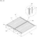
- FIG. 4 illustrates a cell stack assembly 100 and a cover 150 that can be coupled to the cell stack assembly 100 according to an embodiment of the present invention.
- the cell stack assembly 100 may further include a cover 150.
- the cover 150 can be coupled to the support block 140 to cover at least one of upper and lower parts of the cell stack 110 that are open to the outside.
- the cover 150 may include through holes corresponding to the fastening holes 141 of the support block 140 in the area where it abuts and couples to the support block 140. That is, the cover 150 may include through holes perforated on both edges for bolts B to pass through.
- the cover 150 may include an upper cover 151 coupled to the support block 140 at an upper part of the cell stack assembly 100, and a lower cover 152 coupled to the support block 140 at a lower part of the cell stack assembly 100.
- FIG. 5 is a perspective view of a cell stack assembly 100 with an upper cover 151 and a lower cover 152 coupled to a support block 140 according to an embodiment of the present invention.
- the upper cover 151 is coupled to an upper surface of the support block 140
- the lower cover 152 is coupled to a lower surface of the support block 140.
- the upper cover 151 and the lower cover 152 may be screw coupled to the support block 140 by bolts B inserted through the through holes and into fastening holes 141 formed in the upper and lower parts of the support block 140, respectively.
- the cover 150 may be temporarily used to protect the cell stack 110 when it is open to the outside, and may be separated from the cell stack assembly 100 at any time as needed.
- FIG. 6 is a cross-sectional view of the cell stack assembly 100 of FIG. 5 .
- the lower cover 152 may be coupled with the support block 140 at the lower part of the cell stack 110 to support the lower part of the cell stack 110 so as to prevent the cell stack 110 from sagging downward. Furthermore, the cell stack 110 may be enclosed and protected from the outside by the support block 140 covering two sides, end plates 130 covering the front and back, and a cover 150 covering the upper and lower parts.
- a battery pack 1000 according to an embodiment of the present invention includes a cell stack assembly 100 according to embodiments of the present invention, and a pack case 200 in which the cell stack assembly 100 is disposed.
- the battery pack 1000 according to the embodiment of the present invention may further include a pack case cover (not shown) coupled to the pack case 200 to cover an upper part of the cell stack assembly 100 at an upper part of the pack case 200, as needed.
- FIG. 7 illustrates a battery pack 1000 according to the embodiment of the present invention, with a plurality of cell stack assemblies 100 disposed within the pack case 200.
- the pack case 200 includes a lower plate 210 supporting a lower part of the disposed cell stack assembly 100 and side walls 220 along edges of the lower plate 210 to laterally surround the plurality of the cell stack assembles 100.
- the plurality of the cell stack assemblies 100 may be disposed within the pack case 200 such that at least one support block 140 of a cell stack assembly 100 faces a support block 140 of another cell stack assembly 100 neighboring thereto.
- the pack case 200 may include a center partition wall 230 across its center, and the cell stack assembly 100 may be disposed symmetrically about the center partition wall 230 as shown in FIG. 7 .
- FIG. 8 is a perspective and partial cross-sectional view of a pair of cell stack assemblies 100 disposed adjacent to each other within the pack case 200.
- the support blocks 140 of neighboring cell stack assemblies 100 preferably have fastening holes 141 formed in corresponding positions to each other. That is, fastening holes 141 included in the neighboring support blocks 140 are formed in the same position along the longitudinal direction of the support blocks 140.
- the cell stack assemblies 100 disposed in the pack case 200 may be coupled and secured with the pack case 200.
- FIG. 9 is a perspective view of a battery pack 1000 from a lower side according to an embodiment of the present invention.
- the pack case 200 may include a bottom hole 211 passing through the bottom at locations corresponding to the fastening holes 141 formed in the lower part of the cell stack assembly 100.
- the bottom hole 211 may pass through the lower plate 210 of the pack case 200 at a location corresponding to a lower fastening hole 141b formed in the lower part of a support block 140 in the cell stack assembly 100 disposed in the pack case 200.
- Each cell stack assembly 100 disposed in the pack case 200 may be fixed to the pack case 200 by bolts B passing through bottom holes 211 of the pack case 200 and inserted into the fastening holes 141 formed in the support block 140, as shown in FIG. 9 .
- the bolts B may also be inserted into bottom holes 211 of the bottom plate 210 by passing through the upper fastening holes 141a and the lower fastening holes 141b of the support block 140 to fix the cell stack assembly 100 to the pack case 200.
- the support block 140 may include protrusions 142 protruding from at least one of a front side and a rear side of the cell stack assembly 100. Additionally, an inner surface of the side wall 220 in the pack case 200 may include a seating portion 221 protruding toward the cell stack assembly 100.
- FIG. 10 illustrates the support block 140 according to the embodiment of the present invention, more specifically a partial cross-sectional view of a pack case 200 including the seating portion 221 and a cell stack assembly 100 disposed in the pack case 200.
- the cell stack assembly 100 is disposed in the pack case 200 such that the protrusion 142 is seated on the seating portion 221 of the side wall 220.
- FIG. 11 illustrates a cell stack assembly 100 having protrusions 142 formed on one or both sides of the support block 140 and a part of a pack case 200
- FIG. 12 is a plan view of a battery pack 1000 in which the cell stack assembly 100 of FIG. 1 1(a) is disposed within the pack case 200.
- the cell stack assembly 100 may be provided with the protrusions 142 protruding at one side of the support block 140 toward the side wall 220 of the pack case 200 ( FIG. 1 1(a) ), or with the protrusions 142 protruding at both sides of the support block 140 ( FIG. 11(b) ).
- each cell stack assembly 100 is disposed within the pack case 200 with the protrusions 142 facing the side wall 220.
- the cell stack assembly 100 may be fixed to the pack case 200 in a manner that a protrusion 142 of the support block 140 is screw coupled with a seating portion 221 of the side wall 220.
- the seating portion 221 may include a seating hole 221a into which a bolt B can be inserted at the upper part, as shown, and the protrusion 142 may include a protruding hole 142a into which a bolt B can penetrate and be coupled.
- the cell stack assembly 100 may be screw coupled with the side wall 220 by bolts B inserted into the protruding holes 142a and seating holes 221a.
- the battery pack 1000 may further include a fixing member 300 coupled to the support blocks 140 of the cell stack assembly 100 to fix at least two or more cell stack assemblies 100 disposed in the pack case 200. More specifically, the fixing member 300 may include fixing holes 300a at locations corresponding to the fastening holes 141 of each of the support blocks 140. Furthermore, the fixing member 300 may be screw coupled with the support blocks 140 by bolts B inserted into the fixing holes 300a and into the fastening holes 141 corresponding to the fixing holes 300a.
- each cell stack assembly 100 is fixedly connected to each other.
- the battery pack 1000 according to embodiments of the present invention can be modified based on the shape of the fixing member 300.
- the fixing member 300 in the battery pack 1000 may be coupled at both ends to two adjacent support blocks 140.
- FIG. 13 illustrates a configuration of a pair of neighboring cell stack assemblies 100 and a fixing member 300 of the battery pack 1000 according to the first embodiment
- FIG. 14 is a perspective view of a pair of cell stack assemblies 100 coupled by the fixing member 300 of FIG. 13
- FIG. 15 is a plan view of a battery pack 1000 with each cell stack assembly 100 connected by the fixing member 300 of FIG. 13 and disposed within the pack case 200.
- the fixing member 300 in the battery pack 1000 according to the first embodiment of the present invention may include a pair of fixing holes 300a perforated for bolts B to pass through.
- the fixing member 300 is positioned on the support blocks 140 such that each of the fixing holes 300a corresponds to a respective fastening hole 141 in two adjacent support blocks 140, as shown in FIG. 14 , and is screw coupled to each support block 140 by bolts B inserted into the fixing holes 300a and fastening holes 141.
- Adjacent pairs of cell stack assemblies 100 are coupled to each other as the fixing members 300 are screwed with each support block 140.
- the fixing member 300 in the battery pack 1000 according to the second embodiment of the present invention may extend along the longitudinal direction of the support blocks 140 and is coupled at both ends to two adjacent support blocks 140.
- FIG. 16 illustrates a configuration of a pair of neighboring cell stack assemblies 100 and the fixing member 300 of the battery pack 1000 according to the second embodiment.
- the fixing member 300 in the battery pack 1000 according to the second embodiment of the present invention may include a plurality of fixing holes 300a for the bolt B to penetrate.
- the fixing member 300 may extend along the longitudinal direction of the support blocks 140 as shown in FIG. 16 and include a plurality of fixing holes 300a to correspond to the fastening holes 141 of each support block 140 along the extending direction. That is, the fixing holes 300a are spaced apart one another at predetermined spacings along the longitudinal direction of the fixing member 300 to correspond to the fastening holes 141 of each support block 140.
- the fixing member 300 may firmly fix the pair of cell stack assemblies 100 by means of a plurality of bolts B inserted into the fixing holes 300a formed to correspond to the fastening holes 141.
- the fixing member 300 in the battery pack 1000 may extend in a direction across the cell stack 110 included in the cell stack assembly 100.
- the fixing member 300 may be coupled to a plurality of support blocks 140. More specifically, the fixing member 300 may extend to be coupled with at least four or more support blocks 140.
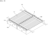
- FIG. 17 illustrates a configuration of a pair of neighboring cell stack assemblies 100 and a fixing member 300 of a battery pack 1000 according to the third embodiment.
- the fixing member 300 in the battery pack 1000 according to the third embodiment of the present invention may include a plurality of fixing holes 300a for the bolt B to penetrate.
- the fixing member 300 may extend in a direction across the cell stack 110 and the support blocks 140 as shown in FIG. 17 , and include a plurality of fixing holes 300a arranged along the extending direction corresponding to the fastening holes 141 of each support block 140. That is, the fixing holes 300a are spaced apart one another at predetermined spacings along the longitudinal direction of the fixing member 300 to correspond to the fastening holes 141 of each support block 140.
- the fixing member 300 can fix a plurality of cell stack assemblies 100 by a plurality of bolts B inserted into the fixing holes 300a formed to correspond to the fastening holes 141, and can also support an upper part of a cell stack 110 received in the fixed cell stack assemblies 100.
- the fixing members 300 in the battery pack 1000 may be mixedly employed within a single battery pack 1000 as desired.
Landscapes
- Chemical & Material Sciences (AREA)
- Chemical Kinetics & Catalysis (AREA)
- Electrochemistry (AREA)
- General Chemical & Material Sciences (AREA)
- Engineering & Computer Science (AREA)
- Manufacturing & Machinery (AREA)
- Battery Mounting, Suspending (AREA)
- Connection Of Batteries Or Terminals (AREA)
Abstract
Description
- The present invention relates to a cell stack assembly comprising a plurality of battery cells stacked together, and a battery pack comprising the cell stack assembly, and more specifically, the present invention is characterized by removing from the battery pack a partition wall for compartmentalizing the cell stack assembly, and by utilizing a support block configuration that can replace the partition wall to increase space utilization within the battery pack.
- This application claims the benefit of priority based on
Korean Patent Applications No. 10-2022-0053655, filed on April 29, 2022 - The types of secondary batteries that are currently widely used include lithium-ion batteries, lithium-polymer batteries, nickel-cadmium batteries, nickel-metal hydride batteries, nickel-zinc batteries, etc. The operating voltage of these individual secondary battery cells, i.e., unit cells, is approximately 2.5V to 4.5V. Therefore, when a higher output voltage is required, a plurality of battery cells may be connected in series to form a battery pack. Additionally, depending on the required charging and discharging capacity of the battery pack, a battery pack may be formed by connecting a plurality of battery cells in parallel. Thus, the number of battery cells included in the battery pack may be varied depending on the required output voltage or charging/discharging capacity.
- Meanwhile, when constructing a battery pack by connecting a plurality battery cells in series or parallel, it is common to first create a battery module that includes at least one battery cell, and then add other components using the at least one battery module to construct a battery pack.
- In conventional battery modules, typically, there is at least one cell stack containing battery cells and a box-shaped metal housing structure, such as a module frame, that accommodates at least one of these cell stacks. In such conventional battery module structures, the energy density of the entire battery pack is reduced due to the weight or volume of the module frame itself, and there is a problem of the weight of the entire battery pack being increased.
- In an attempt to address the aforementioned issues, the conventional module frame structure that wraps and protects the cell stack has been excluded. Instead, in the cell stack, a method of storing and disposing it in a battery pack was attempted only in a configuration coupling a busbar frame and an end plate on the front and back sides, respectively, where the electrode leads are formed.
-
FIG. 1 is a perspective view of a cell stack assembly that excludes a module frame and includes a cell stack, a busbar frame, and an end plate. However, a cell stack assembly of the structure shown inFIG. 1 is difficult to handle and is not easily fixed inside a battery pack. - Therefore, there is a need to explore solutions for providing a cell stack assembly that can further increase energy density by reducing overall weight through lightweighting and that is easy to fix and handle, and a battery pack including the cell stack assembly.
- Thus, the present invention aims to increase the space utilization inside the battery pack by excluding the traditional module frame.
- Furthermore, the present invention aims to provide a structure that supports a cell stack of a plurality of battery cells stacked without a module frame, and for coupling and fixing the cell stack to a battery pack.
- Furthermore, the present invention aims to provide a structure for connecting and fixing a plurality of cell stacks, respectively.
- Other objectives and advantages of the present invention will be understood from the following description and will become more apparent through the embodiments of the present invention. Additionally, the objectives and advantages of the present invention can be easily understood by the means and combinations thereof as expressed in the claims of the patent.
- According to an aspect of the present invention, a cell stack assembly includes: a cell stack in which a plurality of battery cells are stacked; busbar frames including a busbar electrically connected to the cell stack and respectively coupled to a front and a rear of the cell stack; end plates coupled to the busbar frames to cover the busbar; and support blocks respectively coupled to sides of the end plates to cover sides of outermost battery cells of the cell stack, wherein the support blocks include fastening holes at an upper part and a lower part of the support blocks.
- The fastening holes can be spaced along a longitudinal direction of each support block.
- The fastening holes of the support blocks on opposites sides of the cell stack are aligned with each other.
- The cell stack assembly further includes a cover that is coupled to the support blocks to cover at least one of an upper part and a lower part of the cell stack, wherein the cover may include through holes corresponding to the fastening holes of the support blocks where the cover contacts and is coupled to the support block.
- The support blocks and the cover may be screw coupled to each other by bolts which are inserted through the through holes and into the fastening holes.
- According to another aspect of the present invention, the battery pack includes a plurality of cell stack assemblies mentioned above, and a pack case in which the plurality of cell stack assemblies are disposed, wherein the plurality of cell stack assemblies are arranged such that a support block on at least one side of each cell stack assembly faces a support block on a side of a neighboring cell stack assembly.
- The pack case includes bottom holes passing through a bottom of the pack case at locations corresponding to the fastening holes formed at the lower part of the support blocks, wherein the plurality of cell stack assemblies may be coupled to the pack case by bolts inserted into the fastening holes and the bottom holes.
- In addition, the pack case further includes a fixing member coupled to the support blocks of at least two cell stack assemblies of the plurality of cell stack assemblies, wherein the fixing member includes fixing holes at a location corresponding the fastening holes in each of the at least two cell stack assemblies, and wherein the fixing member may be screw coupled to the support blocks by bolts inserted into the fastening holes corresponding to the fixing holes.
- The fixing members may be coupled at each end to two adjacent support blocks to fix a pair of cell stack assemblies of the at least two cell stack assemblies.
- The fixing member extends along a longitudinal direction of two adjacent support blocks of the at least two cell stack assemblies, wherein the fixing holes are spaced apart along a longitudinal direction of the fixing member to correspond to the fastening holes of the two adjacent support blocks.
- The fixing member is coupled to at least four support blocks of the at least two cell stack assemblies.
- The fixing member extends across a cell stack included in the of the at least two cell stack assemblies to support an upper part of the cell stack.
- The pack case includes: a bottom plate supporting a lower part of the plurality of cell stack assemblies disposed in the pack case; and side walls extending along edges of the bottom plate to laterally surround the plurality of cell stack assemblies, wherein an inner surface of the side walls comprises a seating portion protruding toward the plurality of cell stack assemblies, wherein each support block of the plurality of cell stack assemblies comprises a protrusion protruding from at least one of a front side and a rear side of the plurality of cell stack assemblies, and wherein each protrusion is seated on the seating portion of the side wall.
- The seating portion includes seating holes at an upper part of the seating portion, each protrusion includes a protruding hole, and the plurality of cell stack assemblies may be screw coupled to the side walls by bolts inserted into the protruding holes and the seating holes.
- According to the present invention, the energy density of the battery pack can be increased by improving the utilization of space inside the battery pack.
-
-
FIG. 1 shows a conventional cell stack assembly. -
FIG. 2 is an exploded perspective view of a cell stack assembly according to an embodiment of the present invention. -
FIG. 3 is a perspective view of a cell stack assembly according to an embodiment of the present invention. -
FIG. 4 is a perspective view of a cover and a cell stack assembly according to an embodiment of the present invention. -
FIG. 5 is a perspective view of a cell stack assembly with an upper cover and a lower cover coupled to a support block according to an embodiment of the present invention. -
FIG. 6 is a cross-sectional view of the cell stack assembly ofFIG. 5 . -
FIG. 7 is a perspective view of a battery pack according to an embodiment of the present invention. -
FIG. 8 is a perspective view of a pair of cell stack assemblies disposed adjacent to each other according to an embodiment of the present invention. -
FIG. 9 is a perspective view of a pack case from a lower side according to an embodiment of the present invention. -
FIG. 10 illustrates a support block according to an embodiment of the present invention. -
FIG. 11 illustrates a cell stack assembly and pack case in which the support block ofFIG. 10 is applied. -
FIG. 12 is a plan view of a battery pack including a cell stack assembly with the support block ofFIG. 1 1(a) and a pack case in which the cell stack assembly is disposed. -
FIG. 13 illustrates a fixing member and cell stack assembly included in a battery pack according to an embodiment of the present invention. -
FIG. 14 is a perspective view of a pair of cell stack assemblies with the fixing member ofFIG. 13 . -
FIG. 15 is a plan view of a battery pack including the cell stack assembly ofFIG. 13 with the fixing member, and a pack case in which the cell stack assembly is disposed. -
FIG. 16 illustrates a fixing member and cell stack assemblies in a battery pack according to another embodiment of the present invention. -
FIG. 17 illustrates a fixing member and cell stack assemblies in a battery pack according to still another embodiment of the present invention. - Hereinafter, preferred embodiments of the present invention will be described in detail with reference to the accompanying drawings. Before doing so, it should be noted that the terms and words used in this specification and claims are not to be construed in their ordinary or dictionary sense, but rather in a sense and concept consistent with the technical idea of the invention, based on the principle that the inventor may properly define the concept of a term to best describe his invention.
- Accordingly, it is to be understood that the embodiments described herein and the configurations illustrated in the drawings are only the most preferred embodiments of the present invention and do not represent all of the technical ideas of the present invention, and that there may be various equivalents and modifications that may be substituted for them at the time of filing.
- Furthermore, in describing the present invention, where it is deemed that a detailed description of relevant prior art configurations or features would obscure the essence of the present invention, such detailed description is omitted.
- Since the embodiments of the present invention are provided to more fully illustrate the invention to those of ordinary skill in the art, the shapes and sizes of the components in the drawings may be exaggerated, omitted, or shown schematically for clarity. Accordingly, the dimensions or proportions of each component are not intended to be entirely representative of actual dimensions or proportions.
- The present invention relates to a cell stack assembly and a battery pack comprising the cell stack assembly. Hereinafter, the cell stack assembly according to an embodiment of the present invention will be described with reference to
FIGS. 2 through 6 , and the battery pack according to an embodiment of the present invention will be described with reference toFIGS. 7 through 17 . -
FIG. 2 is an exploded perspective view of acell stack assembly 100 according to an embodiment of the present invention, andFIG. 3 is a perspective view of acell stack assembly 100 according to an embodiment of the present invention. - Referring to
FIGS. 2 and 3 , thecell stack assembly 100 of the embodiment comprises acell stack 110, abusbar frame 120, anend plate 130, and asupport block 140. - The
cell stack 110 includes a plurality of stackedbattery cells 111. Each of thebattery cells 111 includes an electrode assembly therein, a pair of electrode leads electrically connected to the electrode assembly, and a battery case enclosing the electrode assembly such that the electrode leads are drawn outwardly. In this case, the electrode leads may be drawn out from both sides of the battery case. - The
busbar frame 120 includes a busbar (not shown) electrically connected to thebattery cell 111. - The
busbar frame 120 may be tightly coupled to thecell stack 110 at the front side and rear side of thecell stack 110 such that the electrode leads of eachbattery cell 111 included in thecell stack 110 are connected to the busbar. - The
end plate 130 is coupled with thebusbar frame 120 covering the busbar 121 to protect the busbar 121 and electrode leads and the like from external impact. - Furthermore, the
end plate 130 collectively fixes each of thebattery cells 111 included in thecell stack 110. - The support blocks 140 are coupled to both sides of the
end plate 130, as shown inFIG. 3 , to cover corresponding sides of thebattery cell 111 located at the outermost edge of thecell stack 110. - The
support block 140 may include the same material as a partition wall that is conventionally installed to partition the interior of thebattery pack 1000 and isolate each battery module. Thesupport block 140 may preferably include a flame retardant material and/or a heat resistant material. - The
support block 140 may be screw coupled to theend plate 130, or may be coupled to theend plate 130 by methods such as adhesion and heat-sealing. - The support blocks 140, while being coupled with the
end plate 130, are in close contact with thebattery cells 111 located at the outermost edge of thecell stack 110, thereby protecting thecell stack 110. - The
support block 140 includes afastening hole 141 into which bolts B can be inserted in the upper and lower parts, as shown inFIG. 2 . - A plurality of the fastening holes 141 may be formed at predetermined spacings along the longitudinal direction of the
support block 140. - The fastening holes 141 formed in each of the support blocks 140 may be provided in positions opposite to each other with the
cell stack 110 intervening therebetween. - The
fastening hole 141 may include anupper fastening hole 141a on an upper part of thesupport block 140 and alower fastening hole 141b on a lower part of thesupport block 140. - The
upper fastening hole 141a and thelower fastening hole 141b on the upper and lower parts of thesupport block 140, respectively, may be separated from each other, or may be connected to each other by penetrating thesupport block 140 in the thickness direction. -
FIG. 4 illustrates acell stack assembly 100 and a cover 150 that can be coupled to thecell stack assembly 100 according to an embodiment of the present invention. - As shown in
FIG. 4 , thecell stack assembly 100 according to the embodiment may further include a cover 150. The cover 150 can be coupled to thesupport block 140 to cover at least one of upper and lower parts of thecell stack 110 that are open to the outside. - The cover 150 may include through holes corresponding to the fastening holes 141 of the
support block 140 in the area where it abuts and couples to thesupport block 140. That is, the cover 150 may include through holes perforated on both edges for bolts B to pass through. - The cover 150 may include an
upper cover 151 coupled to thesupport block 140 at an upper part of thecell stack assembly 100, and alower cover 152 coupled to thesupport block 140 at a lower part of thecell stack assembly 100. -
FIG. 5 is a perspective view of acell stack assembly 100 with anupper cover 151 and alower cover 152 coupled to asupport block 140 according to an embodiment of the present invention. - As shown in
FIG. 5 , theupper cover 151 is coupled to an upper surface of thesupport block 140, and thelower cover 152 is coupled to a lower surface of thesupport block 140. - The
upper cover 151 and thelower cover 152 may be screw coupled to thesupport block 140 by bolts B inserted through the through holes and intofastening holes 141 formed in the upper and lower parts of thesupport block 140, respectively. - In the
cell stack assembly 100, the cover 150 may be temporarily used to protect thecell stack 110 when it is open to the outside, and may be separated from thecell stack assembly 100 at any time as needed. -
FIG. 6 is a cross-sectional view of thecell stack assembly 100 ofFIG. 5 . - The
lower cover 152 may be coupled with thesupport block 140 at the lower part of thecell stack 110 to support the lower part of thecell stack 110 so as to prevent thecell stack 110 from sagging downward. Furthermore, thecell stack 110 may be enclosed and protected from the outside by thesupport block 140 covering two sides,end plates 130 covering the front and back, and a cover 150 covering the upper and lower parts. - A
battery pack 1000 according to an embodiment of the present invention includes acell stack assembly 100 according to embodiments of the present invention, and apack case 200 in which thecell stack assembly 100 is disposed. In addition, thebattery pack 1000 according to the embodiment of the present invention may further include a pack case cover (not shown) coupled to thepack case 200 to cover an upper part of thecell stack assembly 100 at an upper part of thepack case 200, as needed. -
FIG. 7 illustrates abattery pack 1000 according to the embodiment of the present invention, with a plurality ofcell stack assemblies 100 disposed within thepack case 200. - Specifically, the
pack case 200 includes alower plate 210 supporting a lower part of the disposedcell stack assembly 100 andside walls 220 along edges of thelower plate 210 to laterally surround the plurality of the cell stack assembles 100. - The plurality of the
cell stack assemblies 100 may be disposed within thepack case 200 such that at least onesupport block 140 of acell stack assembly 100 faces asupport block 140 of anothercell stack assembly 100 neighboring thereto. - The
pack case 200 may include acenter partition wall 230 across its center, and thecell stack assembly 100 may be disposed symmetrically about thecenter partition wall 230 as shown inFIG. 7 . -
FIG. 8 is a perspective and partial cross-sectional view of a pair ofcell stack assemblies 100 disposed adjacent to each other within thepack case 200. - As shown in
FIG. 8 , the support blocks 140 of neighboringcell stack assemblies 100 preferably havefastening holes 141 formed in corresponding positions to each other. That is, fastening holes 141 included in the neighboring support blocks 140 are formed in the same position along the longitudinal direction of the support blocks 140. - The
cell stack assemblies 100 disposed in thepack case 200 may be coupled and secured with thepack case 200. -
FIG. 9 is a perspective view of abattery pack 1000 from a lower side according to an embodiment of the present invention. - The
pack case 200 according to the embodiment of the present invention may include abottom hole 211 passing through the bottom at locations corresponding to the fastening holes 141 formed in the lower part of thecell stack assembly 100. Specifically, thebottom hole 211 may pass through thelower plate 210 of thepack case 200 at a location corresponding to alower fastening hole 141b formed in the lower part of asupport block 140 in thecell stack assembly 100 disposed in thepack case 200. - Each
cell stack assembly 100 disposed in thepack case 200 may be fixed to thepack case 200 by bolts B passing throughbottom holes 211 of thepack case 200 and inserted into the fastening holes 141 formed in thesupport block 140, as shown inFIG. 9 . - Although not illustrated, for convenience, the bolts B may also be inserted into
bottom holes 211 of thebottom plate 210 by passing through theupper fastening holes 141a and thelower fastening holes 141b of thesupport block 140 to fix thecell stack assembly 100 to thepack case 200. - The
support block 140 according to an embodiment of the present invention may includeprotrusions 142 protruding from at least one of a front side and a rear side of thecell stack assembly 100. Additionally, an inner surface of theside wall 220 in thepack case 200 may include aseating portion 221 protruding toward thecell stack assembly 100. -
FIG. 10 illustrates thesupport block 140 according to the embodiment of the present invention, more specifically a partial cross-sectional view of apack case 200 including theseating portion 221 and acell stack assembly 100 disposed in thepack case 200. - Referring to
FIG. 10 , thecell stack assembly 100 is disposed in thepack case 200 such that theprotrusion 142 is seated on theseating portion 221 of theside wall 220. -
FIG. 11 illustrates acell stack assembly 100 havingprotrusions 142 formed on one or both sides of thesupport block 140 and a part of apack case 200, andFIG. 12 is a plan view of abattery pack 1000 in which thecell stack assembly 100 ofFIG. 1 1(a) is disposed within thepack case 200. - Referring to
FIG. 11 , thecell stack assembly 100 may be provided with theprotrusions 142 protruding at one side of thesupport block 140 toward theside wall 220 of the pack case 200 (FIG. 1 1(a) ), or with theprotrusions 142 protruding at both sides of the support block 140 (FIG. 11(b) ). - Referring to
FIG. 12 , eachcell stack assembly 100 is disposed within thepack case 200 with theprotrusions 142 facing theside wall 220. - The
cell stack assembly 100 may be fixed to thepack case 200 in a manner that aprotrusion 142 of thesupport block 140 is screw coupled with aseating portion 221 of theside wall 220. Specifically, theseating portion 221 may include aseating hole 221a into which a bolt B can be inserted at the upper part, as shown, and theprotrusion 142 may include a protrudinghole 142a into which a bolt B can penetrate and be coupled. - The
cell stack assembly 100 may be screw coupled with theside wall 220 by bolts B inserted into the protrudingholes 142a andseating holes 221a. - The
battery pack 1000 may further include a fixingmember 300 coupled to the support blocks 140 of thecell stack assembly 100 to fix at least two or morecell stack assemblies 100 disposed in thepack case 200. More specifically, the fixingmember 300 may include fixingholes 300a at locations corresponding to the fastening holes 141 of each of the support blocks 140. Furthermore, the fixingmember 300 may be screw coupled with the support blocks 140 by bolts B inserted into the fixingholes 300a and into the fastening holes 141 corresponding to the fixingholes 300a. - By the coupling, each
cell stack assembly 100 is fixedly connected to each other. - The
battery pack 1000 according to embodiments of the present invention can be modified based on the shape of the fixingmember 300. - Hereinafter, the
battery pack 1000 according to embodiments of the present invention will be described with reference toFIGS. 13 through 17 . - The fixing
member 300 in thebattery pack 1000 according to a first embodiment of the present invention may be coupled at both ends to two adjacent support blocks 140. -
FIG. 13 illustrates a configuration of a pair of neighboringcell stack assemblies 100 and a fixingmember 300 of thebattery pack 1000 according to the first embodiment,FIG. 14 is a perspective view of a pair ofcell stack assemblies 100 coupled by the fixingmember 300 ofFIG. 13 , andFIG. 15 is a plan view of abattery pack 1000 with eachcell stack assembly 100 connected by the fixingmember 300 ofFIG. 13 and disposed within thepack case 200. - The fixing
member 300 in thebattery pack 1000 according to the first embodiment of the present invention may include a pair of fixingholes 300a perforated for bolts B to pass through. - The fixing
member 300 is positioned on the support blocks 140 such that each of the fixingholes 300a corresponds to arespective fastening hole 141 in two adjacent support blocks 140, as shown inFIG. 14 , and is screw coupled to each support block 140 by bolts B inserted into the fixingholes 300a and fastening holes 141. - Adjacent pairs of
cell stack assemblies 100 are coupled to each other as the fixingmembers 300 are screwed with eachsupport block 140. - The fixing
member 300 in thebattery pack 1000 according to the second embodiment of the present invention may extend along the longitudinal direction of the support blocks 140 and is coupled at both ends to two adjacent support blocks 140. -
FIG. 16 illustrates a configuration of a pair of neighboringcell stack assemblies 100 and the fixingmember 300 of thebattery pack 1000 according to the second embodiment. - The fixing
member 300 in thebattery pack 1000 according to the second embodiment of the present invention may include a plurality of fixingholes 300a for the bolt B to penetrate. - The fixing
member 300 may extend along the longitudinal direction of the support blocks 140 as shown inFIG. 16 and include a plurality of fixingholes 300a to correspond to the fastening holes 141 of each support block 140 along the extending direction. That is, the fixingholes 300a are spaced apart one another at predetermined spacings along the longitudinal direction of the fixingmember 300 to correspond to the fastening holes 141 of eachsupport block 140. - The fixing
member 300 may firmly fix the pair ofcell stack assemblies 100 by means of a plurality of bolts B inserted into the fixingholes 300a formed to correspond to the fastening holes 141. - The fixing
member 300 in thebattery pack 1000 according to a third embodiment of the present invention may extend in a direction across thecell stack 110 included in thecell stack assembly 100. The fixingmember 300 may be coupled to a plurality of support blocks 140. More specifically, the fixingmember 300 may extend to be coupled with at least four or more support blocks 140. -
FIG. 17 illustrates a configuration of a pair of neighboringcell stack assemblies 100 and a fixingmember 300 of abattery pack 1000 according to the third embodiment. - The fixing
member 300 in thebattery pack 1000 according to the third embodiment of the present invention may include a plurality of fixingholes 300a for the bolt B to penetrate. - The fixing
member 300 may extend in a direction across thecell stack 110 and the support blocks 140 as shown inFIG. 17 , and include a plurality of fixingholes 300a arranged along the extending direction corresponding to the fastening holes 141 of eachsupport block 140. That is, the fixingholes 300a are spaced apart one another at predetermined spacings along the longitudinal direction of the fixingmember 300 to correspond to the fastening holes 141 of eachsupport block 140. - The fixing
member 300 can fix a plurality ofcell stack assemblies 100 by a plurality of bolts B inserted into the fixingholes 300a formed to correspond to the fastening holes 141, and can also support an upper part of acell stack 110 received in the fixedcell stack assemblies 100. - The fixing
members 300 in thebattery pack 1000 according to the above three embodiments may be mixedly employed within asingle battery pack 1000 as desired. - The present invention has been described in more detail above with reference to the drawings and embodiments. However, it is to be understood that the configurations shown in the drawings or embodiments described herein are only one embodiment of the invention and do not represent all of the technical ideas of the invention, and that there may be various equivalents and modifications that may replace them at the time of filing the present application.
Claims (14)
- A cell stack assembly comprising:a cell stack in which a plurality of battery cells are stacked;busbar frames comprising a busbar electrically connected to the cell stack and respectively coupled to a front and a rear of the cell stack;end plates coupled to the busbar frames to cover the busbar; andsupport blocks respectively coupled to sides of the end plates to cover sides of outermost battery cells of the cell stack,wherein the support blocks comprise fastening holes at an upper part and a lower part of the support blocks.
- The cell stack assembly of claim 1, wherein the fastening holes are spaced along a longitudinal direction of each support block.
- The cell stack assembly of claim 1, wherein the fastening holes of the support blocks on opposites sides of the cell stack are aligned with each other.
- The cell stack assembly of claim 1, further comprising:a cover that is coupled to the support blocks to cover at least one of an upper part and a lower part of the cell stack,wherein the cover comprises through holes corresponding to the fastening holes of the support blocks where the cover contacts and is coupled to the support blocks.
- The cell stack assembly of claim 4, wherein the support blocks and the cover are screw coupled to each other by bolts which are inserted through the through holes and into the fastening holes.
- A battery pack comprising:a plurality of cell stack assemblies of claim 1; anda pack case in which the plurality of cell stack assemblies are disposed,wherein the plurality of cell stack assemblies are arranged such that a support block on at least one side of each cell stack assembly faces a support block on a side of a neighboring cell stack assembly.
- The battery pack of claim 6, wherein the pack case comprises bottom holes passing through a bottom of the pack case at locations corresponding to the fastening holes formed at the lower part of the support blocks, and
wherein the plurality of cell stack assemblies are coupled to the pack case by bolts inserted into the fastening holes and the bottom holes. - The battery pack of claim 6, further comprising:a fixing member coupled to the support blocks of at least two cell stack assemblies of the plurality of cell stack assemblies,wherein the fixing member comprises fixing holes at a location corresponding to the fastening holes in each of the at least two cell stack assemblies, andwherein the fixing member is screw coupled to the support blocks by bolts inserted into the fastening holes corresponding to the fixing holes.
- The battery pack of claim 8, wherein the fixing member is coupled at each end to two adjacent support blocks to fix a pair of cell stack assemblies of the at least two cell stack assemblies.
- The battery pack of claim 8, wherein the fixing member extends along a longitudinal direction of two adjacent support blocks of the at least two cell stack assemblies, and
wherein the fixing holes are spaced apart along a longitudinal direction of the fixing member to correspond to the fastening holes of the two adjacent support blocks. - The battery pack of claim 8, wherein the fixing member is coupled to at least four support blocks of the at least two cell stack assemblies.
- The battery pack of claim 11, wherein the fixing member extends across a cell stack included in the at least two cell stack assemblies to support an upper part of the cell stack.
- The battery pack of claim 6, wherein the pack case comprises:a bottom plate supporting a lower part of the plurality of cell stack assemblies disposed in the pack case; andside walls extending along edges of the bottom plate to laterally surround the plurality of cell stack assemblies,wherein an inner surface of the side walls comprises a seating portion protruding toward the plurality of cell stack assemblies,wherein each support block of the plurality of cell stack assemblies comprises a protrusion protruding from at least one of a front side and a rear side of the plurality of cell stack assemblies, andwherein each protrusion is seated on the seating portion of the side wall.
- The battery pack of claim 13, wherein the seating portion comprises seating holes at an upper part of the seating portion,wherein each protrusion comprises a protruding hole, andwherein the plurality of cell stack assemblies are screw coupled to the side walls by bolts inserted into the protruding holes and the seating holes.
Applications Claiming Priority (2)
| Application Number | Priority Date | Filing Date | Title |
|---|---|---|---|
| KR1020220053655A KR102695974B1 (en) | 2022-04-29 | 2022-04-29 | A cell stack assembly and a battery pack comprising the cell stack assembly |
| PCT/KR2023/005717 WO2023211161A2 (en) | 2022-04-29 | 2023-04-27 | Cell stack assembly, and battery pack comprising cell stack assembly |
Publications (2)
| Publication Number | Publication Date |
|---|---|
| EP4465424A2 true EP4465424A2 (en) | 2024-11-20 |
| EP4465424A4 EP4465424A4 (en) | 2025-07-02 |
Family
ID=88519206
Family Applications (1)
| Application Number | Title | Priority Date | Filing Date |
|---|---|---|---|
| EP23796804.5A Pending EP4465424A4 (en) | 2022-04-29 | 2023-04-27 | CELL STACK ARRANGEMENT AND BATTERY PACK WITH THE CELL STACK ARRANGEMENT |
Country Status (6)
| Country | Link |
|---|---|
| US (1) | US20250158206A1 (en) |
| EP (1) | EP4465424A4 (en) |
| KR (1) | KR102695974B1 (en) |
| CN (1) | CN118743085A (en) |
| CA (1) | CA3244594A1 (en) |
| WO (1) | WO2023211161A2 (en) |
Families Citing this family (5)
| Publication number | Priority date | Publication date | Assignee | Title |
|---|---|---|---|---|
| KR20250101718A (en) * | 2023-12-27 | 2025-07-04 | 주식회사 엘지에너지솔루션 | Battery pack |
| CN222126799U (en) * | 2024-01-15 | 2024-12-06 | 惠州亿纬锂能股份有限公司 | End plate and end plate assembly |
| KR20250142680A (en) * | 2024-03-22 | 2025-09-30 | 주식회사 엘지에너지솔루션 | Battery pack |
| KR20250146661A (en) * | 2024-04-02 | 2025-10-13 | 주식회사 엘지에너지솔루션 | Battery pack |
| KR20250158416A (en) * | 2024-04-30 | 2025-11-06 | 주식회사 엘지에너지솔루션 | Battery pack |
Family Cites Families (11)
| Publication number | Priority date | Publication date | Assignee | Title |
|---|---|---|---|---|
| JP2015057759A (en) * | 2013-08-09 | 2015-03-26 | 住友電気工業株式会社 | Battery module, battery module unit and battery pack |
| KR101805652B1 (en) * | 2015-08-28 | 2017-12-06 | 삼성에스디아이 주식회사 | Rechargeable battery pack |
| US10516145B2 (en) * | 2016-01-26 | 2019-12-24 | Ford Global Technologies, Llc | Battery pack array retention |
| DE102017208754A1 (en) * | 2017-05-23 | 2018-11-29 | Mahle International Gmbh | Battery system for an electric vehicle |
| KR102319537B1 (en) * | 2017-12-20 | 2021-10-29 | 주식회사 엘지에너지솔루션 | Battery module, battery pack and vehicle comprising the same |
| KR101953351B1 (en) * | 2018-08-01 | 2019-03-04 | 주식회사 이테스 | Non-welding type battery module and battery module assembly using it |
| KR102770325B1 (en) * | 2019-08-02 | 2025-02-18 | 주식회사 엘지에너지솔루션 | Battery pack and vehicle comprising the battery pack |
| KR102744712B1 (en) | 2019-10-08 | 2024-12-18 | 주식회사 엘지에너지솔루션 | Battery pack and vehicle comprising the same |
| US11833419B2 (en) | 2020-03-16 | 2023-12-05 | Tencent America LLC | Method and apparatus for cloud gaming |
| KR102802106B1 (en) * | 2020-07-28 | 2025-05-02 | 에스케이온 주식회사 | Battery pack |
| CN113067107A (en) * | 2021-03-23 | 2021-07-02 | 远景动力技术(江苏)有限公司 | Busbar subassembly, battery module and vehicle |
-
2022
- 2022-04-29 KR KR1020220053655A patent/KR102695974B1/en active Active
-
2023
- 2023-04-27 US US18/837,751 patent/US20250158206A1/en active Pending
- 2023-04-27 EP EP23796804.5A patent/EP4465424A4/en active Pending
- 2023-04-27 CA CA3244594A patent/CA3244594A1/en active Pending
- 2023-04-27 WO PCT/KR2023/005717 patent/WO2023211161A2/en not_active Ceased
- 2023-04-27 CN CN202380022939.5A patent/CN118743085A/en active Pending
Also Published As
| Publication number | Publication date |
|---|---|
| CN118743085A (en) | 2024-10-01 |
| CA3244594A1 (en) | 2025-02-03 |
| EP4465424A4 (en) | 2025-07-02 |
| WO2023211161A2 (en) | 2023-11-02 |
| JP2025506050A (en) | 2025-03-05 |
| KR20230153789A (en) | 2023-11-07 |
| US20250158206A1 (en) | 2025-05-15 |
| WO2023211161A3 (en) | 2024-01-11 |
| KR102695974B1 (en) | 2024-08-19 |
Similar Documents
| Publication | Publication Date | Title |
|---|---|---|
| EP4465424A2 (en) | Cell stack assembly, and battery pack comprising cell stack assembly | |
| US9112202B2 (en) | Battery module | |
| KR20230134660A (en) | Battery module and battery pack including the same | |
| KR102639410B1 (en) | Battery pack | |
| EP4475309A1 (en) | Battery pack | |
| CN216750213U (en) | Battery pack unit, battery pack and mobile energy storage power supply | |
| KR20240077246A (en) | Battery pack | |
| KR20230160094A (en) | Battery modules and battery packs | |
| KR20250164677A (en) | Logical cell, secondary battery module and secondary battery pack including the same | |
| KR20240073552A (en) | Battery module and battery pack including same | |
| EP4560793A1 (en) | Cell assembly and battery pack comprising same | |
| JP2025521021A (en) | Cell assembly and battery pack including same | |
| JP7678215B2 (en) | Battery pack | |
| EP4456285A1 (en) | Logical cell, secondary battery module, and secondary battery pack comprising same | |
| CN215644729U (en) | Battery module for battery pack and battery pack | |
| CN113451694A (en) | Electricity storage device | |
| KR101936414B1 (en) | Battery cell having a structure for simultaneous storage and battery pack using the battery cell | |
| JP7850284B2 (en) | Cell stack assembly and battery pack including the above cell stack assembly | |
| KR102953462B1 (en) | Battery pack | |
| CN119856331A (en) | Battery pack | |
| EP4629359A1 (en) | Battery pack and energy storage device including same | |
| KR20240166897A (en) | Battery assembly and battery pack including the same | |
| CN121688299A (en) | Battery pack | |
| KR20240083050A (en) | Battery pack | |
| JP2025527906A (en) | Battery pack |
Legal Events
| Date | Code | Title | Description |
|---|---|---|---|
| STAA | Information on the status of an ep patent application or granted ep patent |
Free format text: STATUS: THE INTERNATIONAL PUBLICATION HAS BEEN MADE |
|
| PUAI | Public reference made under article 153(3) epc to a published international application that has entered the european phase |
Free format text: ORIGINAL CODE: 0009012 |
|
| STAA | Information on the status of an ep patent application or granted ep patent |
Free format text: STATUS: REQUEST FOR EXAMINATION WAS MADE |
|
| 17P | Request for examination filed |
Effective date: 20240813 |
|
| AK | Designated contracting states |
Kind code of ref document: A2 Designated state(s): AL AT BE BG CH CY CZ DE DK EE ES FI FR GB GR HR HU IE IS IT LI LT LU LV MC ME MK MT NL NO PL PT RO RS SE SI SK SM TR |
|
| A4 | Supplementary search report drawn up and despatched |
Effective date: 20250602 |
|
| RIC1 | Information provided on ipc code assigned before grant |
Ipc: H01M 10/04 20060101ALI20250526BHEP Ipc: H01M 50/502 20210101ALI20250526BHEP Ipc: H01M 50/289 20210101ALI20250526BHEP Ipc: H01M 50/271 20210101ALI20250526BHEP Ipc: H01M 50/204 20210101AFI20250526BHEP |
|
| DAV | Request for validation of the european patent (deleted) | ||
| DAX | Request for extension of the european patent (deleted) | ||
| STAA | Information on the status of an ep patent application or granted ep patent |
Free format text: STATUS: EXAMINATION IS IN PROGRESS |
|
| 17Q | First examination report despatched |
Effective date: 20260217 |