EP4465422A1 - Pouch-type battery cell and battery module comprising same - Google Patents
Pouch-type battery cell and battery module comprising same Download PDFInfo
- Publication number
- EP4465422A1 EP4465422A1 EP23863312.7A EP23863312A EP4465422A1 EP 4465422 A1 EP4465422 A1 EP 4465422A1 EP 23863312 A EP23863312 A EP 23863312A EP 4465422 A1 EP4465422 A1 EP 4465422A1
- Authority
- EP
- European Patent Office
- Prior art keywords
- pouch
- battery cell
- case
- shaped battery
- pair
- Prior art date
- Legal status (The legal status is an assumption and is not a legal conclusion. Google has not performed a legal analysis and makes no representation as to the accuracy of the status listed.)
- Pending
Links
Images




Classifications
-
- H—ELECTRICITY
- H01—ELECTRIC ELEMENTS
- H01M—PROCESSES OR MEANS, e.g. BATTERIES, FOR THE DIRECT CONVERSION OF CHEMICAL ENERGY INTO ELECTRICAL ENERGY
- H01M50/00—Constructional details or processes of manufacture of the non-active parts of electrochemical cells other than fuel cells, e.g. hybrid cells
- H01M50/10—Primary casings; Jackets or wrappings
- H01M50/102—Primary casings; Jackets or wrappings characterised by their shape or physical structure
- H01M50/105—Pouches or flexible bags
-
- B—PERFORMING OPERATIONS; TRANSPORTING
- B29—WORKING OF PLASTICS; WORKING OF SUBSTANCES IN A PLASTIC STATE IN GENERAL
- B29C—SHAPING OR JOINING OF PLASTICS; SHAPING OF MATERIAL IN A PLASTIC STATE, NOT OTHERWISE PROVIDED FOR; AFTER-TREATMENT OF THE SHAPED PRODUCTS, e.g. REPAIRING
- B29C65/00—Joining or sealing of preformed parts, e.g. welding of plastics materials; Apparatus therefor
- B29C65/02—Joining or sealing of preformed parts, e.g. welding of plastics materials; Apparatus therefor by heating, with or without pressure
- B29C65/18—Joining or sealing of preformed parts, e.g. welding of plastics materials; Apparatus therefor by heating, with or without pressure using heated tools
-
- B—PERFORMING OPERATIONS; TRANSPORTING
- B29—WORKING OF PLASTICS; WORKING OF SUBSTANCES IN A PLASTIC STATE IN GENERAL
- B29C—SHAPING OR JOINING OF PLASTICS; SHAPING OF MATERIAL IN A PLASTIC STATE, NOT OTHERWISE PROVIDED FOR; AFTER-TREATMENT OF THE SHAPED PRODUCTS, e.g. REPAIRING
- B29C66/00—General aspects of processes or apparatus for joining preformed parts
- B29C66/01—General aspects dealing with the joint area or with the area to be joined
- B29C66/03—After-treatments in the joint area
- B29C66/032—Mechanical after-treatments
- B29C66/0324—Reforming or reshaping the joint, e.g. folding over
-
- B—PERFORMING OPERATIONS; TRANSPORTING
- B29—WORKING OF PLASTICS; WORKING OF SUBSTANCES IN A PLASTIC STATE IN GENERAL
- B29C—SHAPING OR JOINING OF PLASTICS; SHAPING OF MATERIAL IN A PLASTIC STATE, NOT OTHERWISE PROVIDED FOR; AFTER-TREATMENT OF THE SHAPED PRODUCTS, e.g. REPAIRING
- B29C66/00—General aspects of processes or apparatus for joining preformed parts
- B29C66/40—General aspects of joining substantially flat articles, e.g. plates, sheets or web-like materials; Making flat seams in tubular or hollow articles; Joining single elements to substantially flat surfaces
- B29C66/41—Joining substantially flat articles ; Making flat seams in tubular or hollow articles
- B29C66/43—Joining a relatively small portion of the surface of said articles
- B29C66/433—Casing-in, i.e. enclosing an element between two sheets by an outlined seam
- B29C66/4332—Casing-in, i.e. enclosing an element between two sheets by an outlined seam by folding a sheet over
-
- H—ELECTRICITY
- H01—ELECTRIC ELEMENTS
- H01M—PROCESSES OR MEANS, e.g. BATTERIES, FOR THE DIRECT CONVERSION OF CHEMICAL ENERGY INTO ELECTRICAL ENERGY
- H01M10/00—Secondary cells; Manufacture thereof
- H01M10/04—Construction or manufacture in general
- H01M10/049—Processes for forming or storing electrodes in the battery container
-
- H—ELECTRICITY
- H01—ELECTRIC ELEMENTS
- H01M—PROCESSES OR MEANS, e.g. BATTERIES, FOR THE DIRECT CONVERSION OF CHEMICAL ENERGY INTO ELECTRICAL ENERGY
- H01M50/00—Constructional details or processes of manufacture of the non-active parts of electrochemical cells other than fuel cells, e.g. hybrid cells
- H01M50/10—Primary casings; Jackets or wrappings
- H01M50/116—Primary casings; Jackets or wrappings characterised by the material
- H01M50/124—Primary casings; Jackets or wrappings characterised by the material having a layered structure
- H01M50/126—Primary casings; Jackets or wrappings characterised by the material having a layered structure comprising three or more layers
- H01M50/129—Primary casings; Jackets or wrappings characterised by the material having a layered structure comprising three or more layers with two or more layers of only organic material
-
- H—ELECTRICITY
- H01—ELECTRIC ELEMENTS
- H01M—PROCESSES OR MEANS, e.g. BATTERIES, FOR THE DIRECT CONVERSION OF CHEMICAL ENERGY INTO ELECTRICAL ENERGY
- H01M50/00—Constructional details or processes of manufacture of the non-active parts of electrochemical cells other than fuel cells, e.g. hybrid cells
- H01M50/10—Primary casings; Jackets or wrappings
- H01M50/172—Arrangements of electric connectors penetrating the casing
- H01M50/174—Arrangements of electric connectors penetrating the casing adapted for the shape of the cells
-
- H—ELECTRICITY
- H01—ELECTRIC ELEMENTS
- H01M—PROCESSES OR MEANS, e.g. BATTERIES, FOR THE DIRECT CONVERSION OF CHEMICAL ENERGY INTO ELECTRICAL ENERGY
- H01M50/00—Constructional details or processes of manufacture of the non-active parts of electrochemical cells other than fuel cells, e.g. hybrid cells
- H01M50/10—Primary casings; Jackets or wrappings
- H01M50/172—Arrangements of electric connectors penetrating the casing
- H01M50/174—Arrangements of electric connectors penetrating the casing adapted for the shape of the cells
- H01M50/178—Arrangements of electric connectors penetrating the casing adapted for the shape of the cells for pouch or flexible bag cells
-
- H—ELECTRICITY
- H01—ELECTRIC ELEMENTS
- H01M—PROCESSES OR MEANS, e.g. BATTERIES, FOR THE DIRECT CONVERSION OF CHEMICAL ENERGY INTO ELECTRICAL ENERGY
- H01M50/00—Constructional details or processes of manufacture of the non-active parts of electrochemical cells other than fuel cells, e.g. hybrid cells
- H01M50/10—Primary casings; Jackets or wrappings
- H01M50/183—Sealing members
- H01M50/184—Sealing members characterised by their shape or structure
-
- H—ELECTRICITY
- H01—ELECTRIC ELEMENTS
- H01M—PROCESSES OR MEANS, e.g. BATTERIES, FOR THE DIRECT CONVERSION OF CHEMICAL ENERGY INTO ELECTRICAL ENERGY
- H01M50/00—Constructional details or processes of manufacture of the non-active parts of electrochemical cells other than fuel cells, e.g. hybrid cells
- H01M50/10—Primary casings; Jackets or wrappings
- H01M50/183—Sealing members
- H01M50/186—Sealing members characterised by the disposition of the sealing members
-
- H—ELECTRICITY
- H01—ELECTRIC ELEMENTS
- H01M—PROCESSES OR MEANS, e.g. BATTERIES, FOR THE DIRECT CONVERSION OF CHEMICAL ENERGY INTO ELECTRICAL ENERGY
- H01M50/00—Constructional details or processes of manufacture of the non-active parts of electrochemical cells other than fuel cells, e.g. hybrid cells
- H01M50/10—Primary casings; Jackets or wrappings
- H01M50/183—Sealing members
- H01M50/19—Sealing members characterised by the material
- H01M50/198—Sealing members characterised by the material characterised by physical properties, e.g. adhesiveness or hardness
-
- H—ELECTRICITY
- H01—ELECTRIC ELEMENTS
- H01M—PROCESSES OR MEANS, e.g. BATTERIES, FOR THE DIRECT CONVERSION OF CHEMICAL ENERGY INTO ELECTRICAL ENERGY
- H01M50/00—Constructional details or processes of manufacture of the non-active parts of electrochemical cells other than fuel cells, e.g. hybrid cells
- H01M50/20—Mountings; Secondary casings or frames; Racks, modules or packs; Suspension devices; Shock absorbers; Transport or carrying devices; Holders
- H01M50/204—Racks, modules or packs for multiple batteries or multiple cells
- H01M50/207—Racks, modules or packs for multiple batteries or multiple cells characterised by their shape
- H01M50/211—Racks, modules or packs for multiple batteries or multiple cells characterised by their shape adapted for pouch cells
-
- B—PERFORMING OPERATIONS; TRANSPORTING
- B29—WORKING OF PLASTICS; WORKING OF SUBSTANCES IN A PLASTIC STATE IN GENERAL
- B29L—INDEXING SCHEME ASSOCIATED WITH SUBCLASS B29C, RELATING TO PARTICULAR ARTICLES
- B29L2031/00—Other particular articles
- B29L2031/34—Electrical apparatus, e.g. sparking plugs or parts thereof
- B29L2031/3468—Batteries, accumulators or fuel cells
-
- H—ELECTRICITY
- H01—ELECTRIC ELEMENTS
- H01M—PROCESSES OR MEANS, e.g. BATTERIES, FOR THE DIRECT CONVERSION OF CHEMICAL ENERGY INTO ELECTRICAL ENERGY
- H01M50/00—Constructional details or processes of manufacture of the non-active parts of electrochemical cells other than fuel cells, e.g. hybrid cells
- H01M50/10—Primary casings; Jackets or wrappings
- H01M50/116—Primary casings; Jackets or wrappings characterised by the material
- H01M50/124—Primary casings; Jackets or wrappings characterised by the material having a layered structure
-
- Y—GENERAL TAGGING OF NEW TECHNOLOGICAL DEVELOPMENTS; GENERAL TAGGING OF CROSS-SECTIONAL TECHNOLOGIES SPANNING OVER SEVERAL SECTIONS OF THE IPC; TECHNICAL SUBJECTS COVERED BY FORMER USPC CROSS-REFERENCE ART COLLECTIONS [XRACs] AND DIGESTS
- Y02—TECHNOLOGIES OR APPLICATIONS FOR MITIGATION OR ADAPTATION AGAINST CLIMATE CHANGE
- Y02E—REDUCTION OF GREENHOUSE GAS [GHG] EMISSIONS, RELATED TO ENERGY GENERATION, TRANSMISSION OR DISTRIBUTION
- Y02E60/00—Enabling technologies; Technologies with a potential or indirect contribution to GHG emissions mitigation
- Y02E60/10—Energy storage using batteries
Definitions
- the present invention relates to a pouch-shaped battery cell and a battery module including the same, and more particularly to a pouch-shaped battery cell capable of preventing or delaying gas venting, thereby contributing to extension of the lifespan thereof, and a battery module including the same.
- Secondary batteries which are capable of being charged and discharged, are intimately used in daily life.
- secondary batteries are used in mobile devices, electric vehicles, and hybrid electric vehicles.
- a lower case and an upper case are prepared using a laminated sheet constituted by an inner resin layer, a metal layer, and an outer resin layer, and the lower case and the upper case are thermally fused to each other in the state in which the lower case and the upper case face each other such that the lower case and the upper case are joined to each other.
- the pouch-shaped battery cell When the pouch-shaped battery cell is used at high temperatures or during charging and discharging of the pouch-shaped battery cell, however, gas is generated, whereby a swelling phenomenon in which the case swells occurs (see FIG. 1 ). In this case, the thermally fused parts are separated from each other, whereby an electrolytic solution in the case leaks to the outside, and therefore a risk of ignition is increased and the lifespan of the battery cell is shortened.
- Patent Document 1 Korean Patent Application Publication No. 2019-0110349 (published on September 30, 2019 )
- the present invention has been made in view of the above problems, and it is an object of the present invention to provide a pouch-shaped battery cell having a structure capable of preventing or delaying gas venting and a battery module including the same.
- the reinforcement portion (133) may be provided on each of a pair of terrace portions (132), wherein each of the pair of terrace portions (132) is disposed so as to face each other.
- the reinforcement portion (133) may be provided in the vicinity of an edge of each of the pair of terrace portions (132).
- the reinforcement portion (133) may be provided in the vicinity of each of opposite edges of each of the pair of terrace portions (132).
- the reinforcement portions (133) may be provided at opposite sides in the state in which the electrode lead (300) is located therebetween.
- the wing portion (131) may be configured to ben toward the side of the pouch case (100) in the overall length direction.
- the reinforcement portion (133) may be configured to bend toward the side of the pouch case (100) in the overall width direction.
- the pouch-shaped battery cell according to the present invention may further include a fixing member (600) located at an outer surface of the reinforcement portion (133) so as to maintain the bent state of the reinforcement portion (133).
- the fixing member (600) may be a belt-shaped tape with an adhesive applied to one surface thereof and may be located so as to wrap the reinforcement portion (133), and one end of the fixing member may be fixed to the lower case (110) and the other end of the fixing member may be fixed to the upper case (120).
- a method of manufacturing a pouch-shaped battery cell includes a first step of cutting a laminate sheet having an inner resin layer, a metal layer, and an outer resin layer to a predetermined shape and size; a second step of forming a pair of receiving spaces in the cut laminate sheet, wherein the pair of receiving spaces are located so as to face each other when the cut laminate sheet is folded to prepare a pouch case; a third step of receiving an electrode assembly in the pair of receiving spaces of the pouch case; and a fourth step of folding the pouch case and thermally fusing edges of the pair of receiving spaces to form a sealed portion, wherein the sealed portion includes a wing portion, a terrace portion, and a reinforcement portion, wherein the wing portion extends along an overall length direction of the pouch case, wherein the terrace portion extends along an overall width direction of the pouch case, and wherein the reinforcement portion has a predetermined shape and area extending outwardly from the terrace portion and is configured to inhibit or delay a gas venting of the pouch-shaped battery cell,
- the method according to the present invention may further include bending the wing portion toward the side of the pouch case in the overall length direction after the fourth step.
- the method according to the present invention may further include bending the reinforcement portion toward the side of the pouch case (100) in the overall width direction after the fourth step.
- the method according to the present invention may further include fixing an outer surface of the reinforcement portion and an outer surface of the pouch case with a tape so as to maintain the bent state of the reinforcement portion.
- the present invention provides a battery module including the pouch-shaped battery cell.
- a reinforcement portion is provided at a sealed portion of the terrace portion, which is vulnerable to venting gas pressure, whereby it is possible to inhibit or delay gas venting, which may contribute to extension of the lifespan of the battery cell.
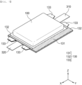
- FIG. 2 is an exploded perspective view of a pouch-shaped battery cell according to a first preferred embodiment of the present invention
- FIG. 3 is a perspective view of the pouch-shaped battery cell according to the first preferred embodiment of the present invention in a sealed state
- FIG. 4 is a plan view of the pouch-shaped battery cell shown in FIG. 3 .
- FIG. 5 is a perspective view of the pouch-shaped battery cell according to the first preferred embodiment of the present invention
- FIG. 6 is a sectional view of the pouch-shaped battery cell taken along line B-B' of FIG. 5 .
- the pouch-shaped battery cell according to the present invention may comprise a pouch case 100, an electrode assembly 200, an electrode lead 300, a protective tape 400, a lead film 500, and a fixing member 600.
- the pouch case 100 may be constituted by a lower case 110 and an upper case 120, and has a pocket type receiving space S configured to receive the electrode assembly 200.
- the pouch case 100 is made of a laminate sheet constituted by an outer resin layer, a metal layer, and an inner resin layer.
- the lower case 110 may be constituted by a first inner resin layer 111 located at the innermost side, a first metal layer 112 located at the center, and a first outer resin layer 113 located at the outermost side.
- a second inner resin layer 121 is located at the innermost side
- a second metal layer 122 is located in the center
- a second outer resin layer 123 is located at the outermost side.
- Each of the first outer resin layer 113 and the second outer resin layer 123 located at an outer side of the pouch case 100 may be made of a heat-resistant polymer that exhibits excellent tensile strength, resistance to moisture permeation, and resistance to air transmission such that the first outer resin layer and the second outer resin layer exhibit high heat resistance and chemical resistance while protecting the electrode assembly 200.
- each of the first outer resin layer and the second outer resin layer may be made of nylon or polyethylene terephthalate; however, the present invention is not limited thereto.
- Each of the metal layers which abut the outer resin layers, i.e. each of the first metal layer 112 and the second metal layer 122 located at the center of the pouch case 100, corresponds to a barrier layer configured to prevent moisture or various kinds of gas from permeating into the battery from the outside.
- An aluminum thin film which is lightweight and easily shapeable, may be used as a preferred material for each metal layer.
- each of the first inner resin layer 111 and the second inner resin layer 121 located at the innermost side of the pouch case 100 is disposed in direct contact with the electrode assembly 200, and therefore each of the first inner resin layer and the second inner resin layer must exhibit high insulation properties and high resistance to an electrolytic solution.
- each of the first inner resin layer and the second inner resin layer must exhibit high sealability in order to hermetically isolate the pouch case from the outside, i.e. a thermally-bonded sealed portion between inner layers must exhibit excellent thermal bonding strength.
- Each of the first inner resin layer 111 and the second inner resin layer 121 may be made of a material selected from among a polyolefin-based resin, such as polypropylene, polyethylene, polyethylene acrylic acid, or polybutylene, a polyurethane resin, and a polyimide resin, which exhibit excellent chemical resistance and high sealability; however, the present invention is not limited thereto, and polypropylene, which exhibits excellent mechanical properties, such as tensile strength, rigidity, surface hardness, and impact resistance, and excellent chemical resistance, is the most preferably used.
- a polyolefin-based resin such as polypropylene, polyethylene, polyethylene acrylic acid, or polybutylene, a polyurethane resin, and a polyimide resin, which exhibit excellent chemical resistance and high sealability
- polypropylene which exhibits excellent mechanical properties, such as tensile strength, rigidity, surface hardness, and impact resistance, and excellent chemical resistance, is the most preferably used.
- the receiving space is shown as being provided in each of the lower case 110 and the upper case 120 in FIGs. 2 and 3 , the receiving space may be provided in any one of the cases.
- thermally-fused sealed portion 130 is provided along edges of the lower case 110 and the upper case 120 that face each other in order to prevent moisture or air from entering the receiving space S of the lower case 110 and the upper case 120.
- the sealed portion 130 is constituted by a wing portion 131 located in an overall length direction (X-axis direction) of the pouch case 100, a terrace portion 132 located in an overall width direction (Y-axis direction) of the pouch case 100, and a reinforcement portion 133 extending from the terrace portion 132.
- the reinforcement portion 133 which inhibits or delays venting of gas generated in the pouch case 100, thereby increasing the lifespan of the battery cell, is located alongside the electrode lead.
- the reinforcement portion it is preferable for the reinforcement portion to be provided at each of a pair of terrace portions 132 located so as to face each other, it is more preferable for the reinforcement portion to be provided at an edge of one side of the terrace portion spaced apart from the electrode lead 300 by a predetermined distance, and it is most preferable for the reinforcement portion to be provided at an edge of the terrace portion 132 located adjacent to the wing portion 131.
- the terrace portion 132 is located so as not to overlap line A-A' such that the terrace portion 132 is not bent with the wing portion 131.
- the shape or area of the reinforcement portion 133 is not particularly limited; however, the reinforcement portion may be trapezoidal in shape to increase the sealing force of the terrace portion 132 while having a small area. At this time, it is preferable for a long side of the reinforcement portion to be connected to the terrace portion 132, and it is more preferable for the reinforcement portion 133 to have a height such that the reinforcement portion does not protrude above the upper case when bent toward the side of the pouch case 100 in the overall width direction.
- the part of the pouch-shaped battery cell on which stress caused by gas generation is concentrated, whereby the seal is easily broken is the terrace portion 132 from which the electrode lead 300 protrudes.
- the edge of the terrace portion spaced apart from the electrode lead 300 by a predetermined distance is the most vulnerable.
- the width W1 of the wing portion which constitutes the sealed portion of the pouch-shaped battery cell, is longer than the width W2 of the terrace portion and the wing portion is fixed in the state in which the wing portion is bent toward the side of the pouch case in the overall width direction, whereby it is possible to maintain high sealing force.
- the terrace portion 132 cannot be bent because the electrode lead is located therein, and there is a disadvantage in that energy density decreases when the width W2 of the terrace portion is increased to increase the sealing force.
- the width W2 of the terrace portion in the vicinity of the electrode lead 300 is also small; however, it is difficult for gas to vent in the vicinity of the electrode lead 300 since the lead part is supported or fixed by a general structure of a module in which the pouch-shaped battery cell is used.
- the reinforcement portion is provided at the edge of one side of the terrace portion spaced apart from the electrode lead 300, as in the present invention, it is possible to increase the sealing force of the terrace portion, whereby it is possible to inhibit or delay gas venting, and therefore it is possible to increase the lifespan of the battery cell.
- the sealing force is further increased.
- the electrode assembly 200 which is seated in the receiving space of the pouch case 100, may be a jelly-roll type electrode assembly, which is configured to have a structure in which a long sheet type negative electrode and a long sheet type positive electrode are wound in the state in which a separator is interposed therebetween, a stacked type electrode assembly including unit cells, each of which is configured to have a structure in which a rectangular positive electrode and a rectangular negative electrode are stacked in the state in which a separator is interposed therebetween, a stacked and folded type electrode assembly, which is configured to have a structure in which unit cells are wound using a long separation film, or a laminated and stacked type electrode assembly, which is configured to have a structure in which unit cells are stacked in the state in which a separator is interposed therebetween and are then attached to each other; however, the present invention is not limited thereto.
- the negative electrode is manufactured by applying a slurry mixture of a negative electrode active material and a binder to a negative electrode current collector.
- the negative electrode active material for example, there may be used carbon, such as a non-graphitizing carbon or a graphite-based carbon; a metal composite oxide, such as Li x Fe 2 O 3 (0 ⁇ x ⁇ 1), Li x WO 2 (0 ⁇ x ⁇ 1), Sn x Me 1-x Me' y O z (Me: Mn, Fe, Pb, Ge; Me': Al, B, P, Si, Group 1, 2, and 3 elements of the periodic table, halogen; 0 ⁇ x ⁇ 1; 1 ⁇ y ⁇ 3; 1 ⁇ z ⁇ 8); lithium metal; a lithium alloy; a silicon-based alloy; a tin-based alloy; a metal oxide, such as SnO, SnO 2 , PbO, PbO 2 , Pb 2 O 3 , Pb 3 O 4 , Sb 2 O 3 , Sb 2 O 4 , Sb 2 O 5 , GeO, GeO 2 , Bi 2 O 3 , Bi 2 O 4 , or Bi 2 O 5 ;
- the positive electrode is manufactured by applying a slurry mixture of a positive electrode active material and a binder to a positive electrode current collector.
- each of the negative electrode current collector and the positive electrode current collector is constituted by a portion to which the slurry including the active material is applied and an uncoated portion to which no slurry is applied.
- the uncoated portion is cut or a separate conductive member is connected to the uncoated portion by ultrasonic welding to form a pair of electrode tabs, i.e. a positive electrode tab 210 and a negative electrode tab 220.
- a pair of electrode leads 300 constituted by a positive electrode lead 310 and a negative electrode lead 320 is electrically connected to the positive electrode tab 210 and the negative electrode tab 220, respectively, and is then exposed out of the pouch case 100.
- each of the pair of electrode tabs and a corresponding one of the pair of electrode leads 300 may be electrically connected to each other by welding, more specifically ultrasonic welding. Coupling by ultrasonic welding is performed according to the principle by which high-frequency vibration generated by an ultrasonic wave of about 20 kHz is applied, and vibration energy is converted into thermal energy due to friction at the interface between the electrode tab and the electrode lead as the result of operation of a horn and an anvil, whereby welding is rapidly performed.
- the protective tape 400 is disposed so as to wrap the part at which the electrode tab and electrode lead 300 overlap each other, i.e. a weld thereof.
- the surfaces of the electrode tab and the electrode lead 300 may not be smooth, leading to poor insulation.
- the inner resin layer is peeled off when the weld and the pouch case 100 come into contact with each other due to impact, whereby the metal layer is exposed, and therefore poor insulation occurs. Consequently, it is preferable to wrap the weld using the protective tape 400 in order to prevent poor insulation.
- the protective tape 400 may be made of an insulating material, such as polypropylene, polyethylene, polyester, or polyimide.
- the material for the protective tape is not limited thereto as long as it is possible to wrap the weld and to maintain the insulated state when in contact with the pouch case 100.
- the lead film 500 which is constituted by a first lead film 510 and a second lead film 520, is spaced apart from the protective tape 400 by a predetermined distance and is located at the sealed portion 130 at which the upper case 120 and the lower case 110, which constitute the pouch case 100, are thermally fused, thereby fixing the electrode lead 300 to the pouch case 100. Consequently, electricity generated by the electrode assembly 200 is prevented from flowing to the pouch case 100 via the electrode lead 300 while the seal of the pouch case 100 is maintained.
- the lead film 500 is made of a non-conductive material that does not conduct electricity well, and an insulating tape that is easily attached to the electrode lead 300 and relatively thin is generally used; however, the present invention is not limited thereto.
- the lead film 500 may be made of any one material or two or more materials selected from the group consisting of polyimide (PI), polypropylene (PP), polyethylene (PE), polyethylene terephthalate (PET), and polyvinyl chloride (PVC), high density polyethylene (HDPE), and an epoxy resin, and the lead film is bonded to the inner resin layer of the pouch case by thermal fusion using heat and pressure.
- PI polyimide
- PP polypropylene
- PE polyethylene
- PET polyethylene terephthalate
- PVC polyvinyl chloride
- HDPE high density polyethylene
- epoxy resin epoxy resin
- the fixing member 600 is configured to fix the reinforcement portion.
- the fixing member 600 is a belt-shaped tape with an adhesive applied to one surface thereof and is located so as to wrap the reinforcement portion 133. That is, one end of the fixing member is fixed to the lower case 110, and the other end of the fixing member is fixed to the upper case 120, whereby the bent state of the reinforcement portion 132 may be maintained.
- FIG. 7 is a perspective view of a pouch-shaped battery cell according to a second preferred embodiment of the present invention in a sealed state
- FIG. 8 is a plan view of the pouch-shaped battery cell shown in FIG. 7
- FIG. 9 is a perspective view of the pouch-shaped battery cell according to the second preferred embodiment of the present invention.
- the second preferred embodiment of the present invention is identical in other configurations to the first preferred embodiment of the present invention except for reinforcement portions, and therefore only the reinforcement portions will hereinafter be described.
- the reinforcement portions according to the second embodiment are located in a pair of terraced portions 132 facing each other and are provided in the vicinity of opposite edges of each terraced portion 132, i.e. opposite sides of the terraced portion in the state in which an electrode lead 300 is located between the reinforcement portions.
- FIG. 10 is a flowchart illustrating the method of manufacturing the pouch-shaped battery cell according to the present invention.
- a method of manufacturing a pouch-type battery cell of the present invention may include a first step of cutting a laminate sheet constituted by an inner resin layer, a metal layer, and an outer resin layer to a predetermined shape and size, a second step of forming a pair of receiving spaces such that the cut laminate sheet is located so as to face the receiving spaces when folded to prepare a pouch case, a third step of receiving an electrode assembly in the receiving spaces of the pouch case, and a fourth step of folding the pouch case and thermally fusing edges of the receiving spaces to form a sealed portion.
- the laminate sheet must be cut in the first step such that a reinforcement portion can be formed.
- the sealed portion is formed by the thermal fusion process in the fourth step, wherein the sealed portion is constituted by a wing portion located in an overall length direction of the pouch case, a terrace portion located in an overall width direction of the pouch case, and a reinforcement portion extending outwardly from the terrace portion.
- the receiving spaces are formed such that the width of the wing portion is greater than the width of the terrace portion after thermal fusion.
- a step of bending the wing portion toward the side of the pouch case in the overall length direction and a step of bending the reinforcement portion toward the side of the pouch case in the overall width direction may be further included after the fourth step, wherein these steps may be simultaneously performed.
- the present invention provides a battery module including the pouch-shaped battery cell and a battery pack including the battery module.
Landscapes
- Chemical & Material Sciences (AREA)
- Chemical Kinetics & Catalysis (AREA)
- Electrochemistry (AREA)
- General Chemical & Material Sciences (AREA)
- Engineering & Computer Science (AREA)
- Mechanical Engineering (AREA)
- Manufacturing & Machinery (AREA)
- Sealing Battery Cases Or Jackets (AREA)
Abstract
Description
- This application claims the benefit of priority to
Korean Patent Application No. 2022-0113985 filed on September 8, 2022 - The present invention relates to a pouch-shaped battery cell and a battery module including the same, and more particularly to a pouch-shaped battery cell capable of preventing or delaying gas venting, thereby contributing to extension of the lifespan thereof, and a battery module including the same.
- With recent development of alternative energies due to air pollution and energy depletion caused as the result of use of fossil fuels, demand for secondary batteries capable of storing electrical energy that is produced has increased. Secondary batteries, which are capable of being charged and discharged, are intimately used in daily life. For example, secondary batteries are used in mobile devices, electric vehicles, and hybrid electric vehicles.
- Required capacities of secondary batteries used as energy sources of various kinds of electronic devices inevitably used in modern society have been increased due to an increase in usage of mobile devices, increasing complexity of the mobile devices, and development of electric vehicles. In order to satisfy demand of users, a plurality of battery cells is disposed in a small-sized device, whereas a battery module including a plurality of battery cells electrically connected to each other or a battery pack including a plurality of battery modules is used in a vehicle, etc.
- Meanwhile, for a pouch-shaped battery cell, a lower case and an upper case are prepared using a laminated sheet constituted by an inner resin layer, a metal layer, and an outer resin layer, and the lower case and the upper case are thermally fused to each other in the state in which the lower case and the upper case face each other such that the lower case and the upper case are joined to each other.
- When the pouch-shaped battery cell is used at high temperatures or during charging and discharging of the pouch-shaped battery cell, however, gas is generated, whereby a swelling phenomenon in which the case swells occurs (see
FIG. 1 ). In this case, the thermally fused parts are separated from each other, whereby an electrolytic solution in the case leaks to the outside, and therefore a risk of ignition is increased and the lifespan of the battery cell is shortened. - (Patent Document 1)
Korean Patent Application Publication No. 2019-0110349 (published on September 30, 2019 - The present invention has been made in view of the above problems, and it is an object of the present invention to provide a pouch-shaped battery cell having a structure capable of preventing or delaying gas venting and a battery module including the same.
- A pouch-shaped battery cell according to the present invention to accomplish the above object includes a pouch case (100) including a lower case (110), an upper case (120), and a sealed portion (130), wherein the lower case (110) has a receiving space, the upper case (120) is located on the lower case (110), and the sealed portion (130) is a thermally-fused three-sided sealed portion located at edges of the lower case (110) and the upper case (120) that face each other; an electrode assembly (200) received in the pouch case (100), the electrode assembly including a positive electrode, a negative electrode, a separator, and a pair of electrode tabs provided at one side or opposite sides thereof; and a pair of electrode leads (300) connected to the pair of electrode tabs, the pair of electrode leads protruding out of the pouch case (100), wherein the sealed portion (130) includes a wing portion (131), a terrace portion (132), and a reinforcement portion (133), wherein the wing portion (131) extends along an overall length direction of the pouch case (100), wherein the terrace portion (132) extends along an overall width direction of the pouch case (100), and wherein the reinforcement portion (133) has a predetermined shape and area extending outwardly from the terrace portion (132) and is configure to inhibit or delay a gas venting of the pouch-shaped battery cell, and wherein the width of the wing portion is greater than the width of the terrace portion.
- Also, in the pouch-shaped battery cell according to the present invention, the reinforcement portion (133) may be provided on each of a pair of terrace portions (132), wherein each of the pair of terrace portions (132) is disposed so as to face each other.
- Also, in the pouch-shaped battery cell according to the present invention, the reinforcement portion (133) may be provided in the vicinity of an edge of each of the pair of terrace portions (132).
- Also, in the pouch-shaped battery cell according to the present invention, the reinforcement portion (133) may be provided in the vicinity of each of opposite edges of each of the pair of terrace portions (132).
- Also, in the pouch-shaped battery cell according to the present invention, the reinforcement portions (133) may be provided at opposite sides in the state in which the electrode lead (300) is located therebetween.
- Also, in the pouch-shaped battery cell according to the present invention, the wing portion (131) may be configured to ben toward the side of the pouch case (100) in the overall length direction.
- Also, in the pouch-shaped battery cell according to the present invention, the reinforcement portion (133) may be configured to bend toward the side of the pouch case (100) in the overall width direction.
- Also, the pouch-shaped battery cell according to the present invention may further include a fixing member (600) located at an outer surface of the reinforcement portion (133) so as to maintain the bent state of the reinforcement portion (133).
- Also, in the pouch-shaped battery cell according to the present invention, the fixing member (600) may be a belt-shaped tape with an adhesive applied to one surface thereof and may be located so as to wrap the reinforcement portion (133), and one end of the fixing member may be fixed to the lower case (110) and the other end of the fixing member may be fixed to the upper case (120).
- In addition, a method of manufacturing a pouch-shaped battery cell according to the present invention includes a first step of cutting a laminate sheet having an inner resin layer, a metal layer, and an outer resin layer to a predetermined shape and size; a second step of forming a pair of receiving spaces in the cut laminate sheet, wherein the pair of receiving spaces are located so as to face each other when the cut laminate sheet is folded to prepare a pouch case; a third step of receiving an electrode assembly in the pair of receiving spaces of the pouch case; and a fourth step of folding the pouch case and thermally fusing edges of the pair of receiving spaces to form a sealed portion, wherein the sealed portion includes a wing portion, a terrace portion, and a reinforcement portion, wherein the wing portion extends along an overall length direction of the pouch case, wherein the terrace portion extends along an overall width direction of the pouch case, and wherein the reinforcement portion has a predetermined shape and area extending outwardly from the terrace portion and is configured to inhibit or delay a gas venting of the pouch-shaped battery cell, and wherein the width of the wing portion is greater than the width of the terrace portion.
- Also, the method according to the present invention may further include bending the wing portion toward the side of the pouch case in the overall length direction after the fourth step.
- Also, the method according to the present invention may further include bending the reinforcement portion toward the side of the pouch case (100) in the overall width direction after the fourth step.
- Also, the method according to the present invention may further include fixing an outer surface of the reinforcement portion and an outer surface of the pouch case with a tape so as to maintain the bent state of the reinforcement portion.
- In addition, the present invention provides a battery module including the pouch-shaped battery cell.
- As is apparent from the above description, in a pouch-shaped battery cell according to the present invention and a battery module including the same, a reinforcement portion is provided at a sealed portion of the terrace portion, which is vulnerable to venting gas pressure, whereby it is possible to inhibit or delay gas venting, which may contribute to extension of the lifespan of the battery cell.
-
-
FIG. 1 is a schematic view showing a pouch-shaped battery cell in a swollen state. -
FIG. 2 is an exploded perspective view of a pouch-shaped battery cell according to a first preferred embodiment of the present invention. -
FIG. 3 is a perspective view of the pouch-shaped battery cell according to the first preferred embodiment of the present invention in a sealed state. -
FIG. 4 is a plan view of the pouch-shaped battery cell shown inFIG. 3 . -
FIG. 5 is a perspective view of the pouch-shaped battery cell according to the first preferred embodiment of the present invention. -
FIG. 6 is a sectional view of the pouch-shaped battery cell taken along line B-B' ofFIG. 5 . -
FIG. 7 is a perspective view of a pouch-shaped battery cell according to a second preferred embodiment of the present invention in a sealed state. -
FIG. 8 is a plan view of the pouch-shaped battery cell shown inFIG. 7 . -
FIG. 9 is a perspective view of the pouch-shaped battery cell according to the second preferred embodiment of the present invention. -
FIG. 10 is a flowchart illustrating a method of manufacturing a pouch-shaped battery cell according to the present invention. - Now, preferred embodiments of the present invention will be described in detail with reference to the accompanying drawings such that the preferred embodiments of the present invention can be easily implemented by a person having ordinary skill in the art to which the present invention pertains. In describing the principle of operation of the preferred embodiments of the present invention in detail, however, a detailed description of known functions and configurations incorporated herein will be omitted when the same may obscure the subject matter of the present invention.
- In addition, the same reference numbers will be used throughout the drawings to refer to parts that perform similar functions or operations. In the case in which one part is said to be connected to another part in the entire specification, not only may the one part be directly connected to the other part, but also, the one part may be indirectly connected to the other part via a further part. In addition, that a certain element is included does not mean that other elements are excluded, but means that such elements may be further included unless mentioned otherwise.
- Hereinafter, a pouch-shaped battery cell according to the present invention and a battery module including the same will be described with reference to the accompanying drawings.
-
FIG. 2 is an exploded perspective view of a pouch-shaped battery cell according to a first preferred embodiment of the present invention,FIG. 3 is a perspective view of the pouch-shaped battery cell according to the first preferred embodiment of the present invention in a sealed state, andFIG. 4 is a plan view of the pouch-shaped battery cell shown inFIG. 3 . - In addition,
FIG. 5 is a perspective view of the pouch-shaped battery cell according to the first preferred embodiment of the present invention, andFIG. 6 is a sectional view of the pouch-shaped battery cell taken along line B-B' ofFIG. 5 . - As shown in
FIGs. 2 to 6 , the pouch-shaped battery cell according to the present invention may comprise apouch case 100, anelectrode assembly 200, anelectrode lead 300, aprotective tape 400, a lead film 500, and afixing member 600. - First, the
pouch case 100 may be constituted by alower case 110 and anupper case 120, and has a pocket type receiving space S configured to receive theelectrode assembly 200. - The
pouch case 100 is made of a laminate sheet constituted by an outer resin layer, a metal layer, and an inner resin layer. - Specifically, the
lower case 110 may be constituted by a firstinner resin layer 111 located at the innermost side, afirst metal layer 112 located at the center, and a firstouter resin layer 113 located at the outermost side. - Even in the
upper case 120, a secondinner resin layer 121 is located at the innermost side, asecond metal layer 122 is located in the center, and a secondouter resin layer 123 is located at the outermost side. - Each of the first
outer resin layer 113 and the secondouter resin layer 123 located at an outer side of thepouch case 100 may be made of a heat-resistant polymer that exhibits excellent tensile strength, resistance to moisture permeation, and resistance to air transmission such that the first outer resin layer and the second outer resin layer exhibit high heat resistance and chemical resistance while protecting theelectrode assembly 200. As an example, each of the first outer resin layer and the second outer resin layer may be made of nylon or polyethylene terephthalate; however, the present invention is not limited thereto. - Each of the metal layers, which abut the outer resin layers, i.e. each of the
first metal layer 112 and thesecond metal layer 122 located at the center of thepouch case 100, corresponds to a barrier layer configured to prevent moisture or various kinds of gas from permeating into the battery from the outside. An aluminum thin film, which is lightweight and easily shapeable, may be used as a preferred material for each metal layer. - Each of the first
inner resin layer 111 and the secondinner resin layer 121 located at the innermost side of thepouch case 100 is disposed in direct contact with theelectrode assembly 200, and therefore each of the first inner resin layer and the second inner resin layer must exhibit high insulation properties and high resistance to an electrolytic solution. In addition, each of the first inner resin layer and the second inner resin layer must exhibit high sealability in order to hermetically isolate the pouch case from the outside, i.e. a thermally-bonded sealed portion between inner layers must exhibit excellent thermal bonding strength. - Each of the first
inner resin layer 111 and the secondinner resin layer 121 may be made of a material selected from among a polyolefin-based resin, such as polypropylene, polyethylene, polyethylene acrylic acid, or polybutylene, a polyurethane resin, and a polyimide resin, which exhibit excellent chemical resistance and high sealability; however, the present invention is not limited thereto, and polypropylene, which exhibits excellent mechanical properties, such as tensile strength, rigidity, surface hardness, and impact resistance, and excellent chemical resistance, is the most preferably used. - Although the receiving space is shown as being provided in each of the
lower case 110 and theupper case 120 inFIGs. 2 and3 , the receiving space may be provided in any one of the cases. - Meanwhile, a thermally-fused sealed
portion 130 is provided along edges of thelower case 110 and theupper case 120 that face each other in order to prevent moisture or air from entering the receiving space S of thelower case 110 and theupper case 120. - It is preferable for the sealed
portion 130 to be constituted by awing portion 131 located in an overall length direction (X-axis direction) of thepouch case 100, aterrace portion 132 located in an overall width direction (Y-axis direction) of thepouch case 100, and areinforcement portion 133 extending from theterrace portion 132. - The
reinforcement portion 133, which inhibits or delays venting of gas generated in thepouch case 100, thereby increasing the lifespan of the battery cell, is located alongside the electrode lead. - Specifically, it is preferable for the reinforcement portion to be provided at each of a pair of
terrace portions 132 located so as to face each other, it is more preferable for the reinforcement portion to be provided at an edge of one side of the terrace portion spaced apart from theelectrode lead 300 by a predetermined distance, and it is most preferable for the reinforcement portion to be provided at an edge of theterrace portion 132 located adjacent to thewing portion 131. - Specifically, on the assumption that the length of the wing portion is L1, the length of the terrace portion is L2, and the
wing portion 131 is bent along line A-A', as shown inFIG. 4 , theterrace portion 132 is located so as not to overlap line A-A' such that theterrace portion 132 is not bent with thewing portion 131. - Here, the shape or area of the
reinforcement portion 133 is not particularly limited; however, the reinforcement portion may be trapezoidal in shape to increase the sealing force of theterrace portion 132 while having a small area. At this time, it is preferable for a long side of the reinforcement portion to be connected to theterrace portion 132, and it is more preferable for thereinforcement portion 133 to have a height such that the reinforcement portion does not protrude above the upper case when bent toward the side of thepouch case 100 in the overall width direction. - In actual application, the part of the pouch-shaped battery cell on which stress caused by gas generation is concentrated, whereby the seal is easily broken, is the
terrace portion 132 from which theelectrode lead 300 protrudes. In particular, the edge of the terrace portion spaced apart from theelectrode lead 300 by a predetermined distance is the most vulnerable. - More specifically, the width W1 of the wing portion, which constitutes the sealed portion of the pouch-shaped battery cell, is longer than the width W2 of the terrace portion and the wing portion is fixed in the state in which the wing portion is bent toward the side of the pouch case in the overall width direction, whereby it is possible to maintain high sealing force. In contrast, the
terrace portion 132 cannot be bent because the electrode lead is located therein, and there is a disadvantage in that energy density decreases when the width W2 of the terrace portion is increased to increase the sealing force. - Of course, the width W2 of the terrace portion in the vicinity of the
electrode lead 300 is also small; however, it is difficult for gas to vent in the vicinity of theelectrode lead 300 since the lead part is supported or fixed by a general structure of a module in which the pouch-shaped battery cell is used. - However, when the reinforcement portion is provided at the edge of one side of the terrace portion spaced apart from the
electrode lead 300, as in the present invention, it is possible to increase the sealing force of the terrace portion, whereby it is possible to inhibit or delay gas venting, and therefore it is possible to increase the lifespan of the battery cell. - In particular, when the
reinforcement portion 133 is bent toward the side of thepouch case 100 in the overall width direction and the bent state of the reinforcement portion is maintained using the fixingmember 600, a description of which will follow, the sealing force is further increased. - Next, the
electrode assembly 200 will be described. Theelectrode assembly 200, which is seated in the receiving space of thepouch case 100, may be a jelly-roll type electrode assembly, which is configured to have a structure in which a long sheet type negative electrode and a long sheet type positive electrode are wound in the state in which a separator is interposed therebetween, a stacked type electrode assembly including unit cells, each of which is configured to have a structure in which a rectangular positive electrode and a rectangular negative electrode are stacked in the state in which a separator is interposed therebetween, a stacked and folded type electrode assembly, which is configured to have a structure in which unit cells are wound using a long separation film, or a laminated and stacked type electrode assembly, which is configured to have a structure in which unit cells are stacked in the state in which a separator is interposed therebetween and are then attached to each other; however, the present invention is not limited thereto. - Specifically, the negative electrode is manufactured by applying a slurry mixture of a negative electrode active material and a binder to a negative electrode current collector.
- As the negative electrode active material, for example, there may be used carbon, such as a non-graphitizing carbon or a graphite-based carbon; a metal composite oxide, such as LixFe2O3 (0≤x≤1), LixWO2 (0≤x≤1), SnxMe1-xMe'yOz (Me: Mn, Fe, Pb, Ge; Me': Al, B, P, Si,
Group 1, 2, and 3 elements of the periodic table, halogen; 0<x≤1; 1≤y≤3; 1≤z≤8); lithium metal; a lithium alloy; a silicon-based alloy; a tin-based alloy; a metal oxide, such as SnO, SnO2, PbO, PbO2, Pb2O3, Pb3O4, Sb2O3, Sb2O4, Sb2O5, GeO, GeO2, Bi2O3, Bi2O4, or Bi2O5; a conductive polymer, such as polyacetylene; a Li-Co-Ni-based material; or a Si-based material, such as Si, SiO, SiO2, or a mixture thereof; however, the present invention is not limited thereto. - The positive electrode is manufactured by applying a slurry mixture of a positive electrode active material and a binder to a positive electrode current collector.
- The positive electrode active material may be constituted, for example, by a layered compound, such as a lithium cobalt oxide (LiCoO2) or a lithium nickel oxide (LiNiO2), or a compound substituted with one or more transition metals; a lithium manganese oxide represented by the chemical formula Li1+xMn2-xO4 (where x = 0 to 0.33) or a lithium manganese oxide, such as LiMnO3, LiMn2O3, or LiMnO2; a lithium copper oxide (Li2CuO2); a vanadium oxide, such as LiV3O8, V2O5, or Cu2V2O7; a Ni-sited lithium nickel oxide represented by the chemical formula LiNi2-xMxO2 (where M = Co, Mn, Al, Cu, Fe, Mg, B, or Ga, and x = 0.01 to 0.3); a lithium manganese composite oxide represented by the chemical formula LiMn2-xMxO2 (where M = Co, Ni, Fe, Cr, Zn, or Ta, and x = 0.01 to 0.1) or the chemical formula Li2Mn3MO8 (where M = Fe, Co, Ni, Cu, or Zn); LiMn2O4 in which a part of Li in the chemical formula is replaced by alkaline earth metal ions; a disulfide compound; or Fe2(MoO4)3; however, the present invention is not limited thereto.
- Meanwhile, each of the negative electrode current collector and the positive electrode current collector is constituted by a portion to which the slurry including the active material is applied and an uncoated portion to which no slurry is applied. The uncoated portion is cut or a separate conductive member is connected to the uncoated portion by ultrasonic welding to form a pair of electrode tabs, i.e. a
positive electrode tab 210 and anegative electrode tab 220. - A pair of electrode leads 300 constituted by a
positive electrode lead 310 and anegative electrode lead 320 is electrically connected to thepositive electrode tab 210 and thenegative electrode tab 220, respectively, and is then exposed out of thepouch case 100. - Here, each of the pair of electrode tabs and a corresponding one of the pair of electrode leads 300 may be electrically connected to each other by welding, more specifically ultrasonic welding. Coupling by ultrasonic welding is performed according to the principle by which high-frequency vibration generated by an ultrasonic wave of about 20 kHz is applied, and vibration energy is converted into thermal energy due to friction at the interface between the electrode tab and the electrode lead as the result of operation of a horn and an anvil, whereby welding is rapidly performed.
- Next, the
protective tape 400 will be described. Theprotective tape 400 is disposed so as to wrap the part at which the electrode tab andelectrode lead 300 overlap each other, i.e. a weld thereof. - Since the electrode tab and the
electrode lead 300 are connected to each other by welding, the surfaces of the electrode tab and theelectrode lead 300 may not be smooth, leading to poor insulation. - Specifically, if the surface of the weld is not smooth, the inner resin layer is peeled off when the weld and the
pouch case 100 come into contact with each other due to impact, whereby the metal layer is exposed, and therefore poor insulation occurs. Consequently, it is preferable to wrap the weld using theprotective tape 400 in order to prevent poor insulation. - Here, the
protective tape 400 may be made of an insulating material, such as polypropylene, polyethylene, polyester, or polyimide. However, the material for the protective tape is not limited thereto as long as it is possible to wrap the weld and to maintain the insulated state when in contact with thepouch case 100. - The lead film 500, which is constituted by a
first lead film 510 and asecond lead film 520, is spaced apart from theprotective tape 400 by a predetermined distance and is located at the sealedportion 130 at which theupper case 120 and thelower case 110, which constitute thepouch case 100, are thermally fused, thereby fixing theelectrode lead 300 to thepouch case 100. Consequently, electricity generated by theelectrode assembly 200 is prevented from flowing to thepouch case 100 via theelectrode lead 300 while the seal of thepouch case 100 is maintained. - It is preferable for the lead film 500 to be made of a non-conductive material that does not conduct electricity well, and an insulating tape that is easily attached to the
electrode lead 300 and relatively thin is generally used; however, the present invention is not limited thereto. - Specifically, the lead film 500 may be made of any one material or two or more materials selected from the group consisting of polyimide (PI), polypropylene (PP), polyethylene (PE), polyethylene terephthalate (PET), and polyvinyl chloride (PVC), high density polyethylene (HDPE), and an epoxy resin, and the lead film is bonded to the inner resin layer of the pouch case by thermal fusion using heat and pressure.
- Next, the fixing
member 600 will be described. As described above, the fixingmember 600 is configured to fix the reinforcement portion. Specifically, the fixingmember 600 is a belt-shaped tape with an adhesive applied to one surface thereof and is located so as to wrap thereinforcement portion 133. That is, one end of the fixing member is fixed to thelower case 110, and the other end of the fixing member is fixed to theupper case 120, whereby the bent state of thereinforcement portion 132 may be maintained. -
FIG. 7 is a perspective view of a pouch-shaped battery cell according to a second preferred embodiment of the present invention in a sealed state,FIG. 8 is a plan view of the pouch-shaped battery cell shown inFIG. 7 , andFIG. 9 is a perspective view of the pouch-shaped battery cell according to the second preferred embodiment of the present invention. - The second preferred embodiment of the present invention is identical in other configurations to the first preferred embodiment of the present invention except for reinforcement portions, and therefore only the reinforcement portions will hereinafter be described.
- The reinforcement portions according to the second embodiment are located in a pair of
terraced portions 132 facing each other and are provided in the vicinity of opposite edges of eachterraced portion 132, i.e. opposite sides of the terraced portion in the state in which anelectrode lead 300 is located between the reinforcement portions. - Next, a method of manufacturing a pouch-shaped battery cell according to the present invention will be described.
FIG. 10 is a flowchart illustrating the method of manufacturing the pouch-shaped battery cell according to the present invention. - Referring to
FIG. 10 , a method of manufacturing a pouch-type battery cell of the present invention may include a first step of cutting a laminate sheet constituted by an inner resin layer, a metal layer, and an outer resin layer to a predetermined shape and size, a second step of forming a pair of receiving spaces such that the cut laminate sheet is located so as to face the receiving spaces when folded to prepare a pouch case, a third step of receiving an electrode assembly in the receiving spaces of the pouch case, and a fourth step of folding the pouch case and thermally fusing edges of the receiving spaces to form a sealed portion. - It is obvious that the laminate sheet must be cut in the first step such that a reinforcement portion can be formed. The reason for this is that the sealed portion is formed by the thermal fusion process in the fourth step, wherein the sealed portion is constituted by a wing portion located in an overall length direction of the pouch case, a terrace portion located in an overall width direction of the pouch case, and a reinforcement portion extending outwardly from the terrace portion.
- In the second step, the receiving spaces are formed such that the width of the wing portion is greater than the width of the terrace portion after thermal fusion.
- Meanwhile, a step of bending the wing portion toward the side of the pouch case in the overall length direction and a step of bending the reinforcement portion toward the side of the pouch case in the overall width direction may be further included after the fourth step, wherein these steps may be simultaneously performed.
- It is also preferable to further perform a step of fixing an outer surface of the reinforcement portion and an outer surface of the pouch case with a tape such that the bent state of the reinforcement portion is maintained after the reinforcement portion is bent.
- The present invention provides a battery module including the pouch-shaped battery cell and a battery pack including the battery module.
- Those skilled in the art to which the present invention pertains will appreciate that various applications and modifications are possible within the category of the present invention based on the above description.
-
- 100: Pouch case
- 110: Lower case
- 111: First inner resin layer 112: First metal layer
- 113: First outer resin layer
- 120: Upper case
- 121: Second inner resin layer 122: Second metal layer
- 123: Second outer resin layer
- 130: Sealed portion
- 131: Wing portion 132: Terrace portion
- 133: Reinforcement portion
- 200: Electrode assembly
- 210: Positive electrode tab 220: Negative electrode tab
- 300: Electrode lead
- 310: Positive electrode lead 320: Negative electrode lead
- 400: Protective tape
- 410: First protective tape 420: Second protective tape
- 500: Lead film
- 510: First lead film 520: Second lead film
- 600: Fixing member
- L1: Length of wing portion L2: Length of terrace portion
- W1: Width of wing portion W2: Width of terrace portion
- S: Receiving space
Claims (14)
- A pouch-shaped battery cell comprising:a pouch case comprising a lower case, an upper case, and a sealed portion, wherein the lower case has a receiving space, the upper case is located on the lower case, and the sealed portion is a thermally-fused three-sided sealed portion located at edges of the lower case and the upper case that face each other;an electrode assembly received in the pouch case, the electrode assembly comprising a positive electrode, a negative electrode, a separator, and a pair of electrode tabs provided at one side or opposite sides thereof; anda pair of electrode leads connected to the pair of electrode tabs, the pair of electrode leads protruding out of the pouch case, whereinthe sealed portion includes a wing portion, a terrace portion, and a reinforcement portion, wherein the wing portion extends along an overall length direction of the pouch case, wherein the terrace portion extends along an overall width direction of the pouch case, and wherein the reinforcement portion has a predetermined shape and area extending outwardly from the terrace portion and is configured to inhibit or delay a gas venting of the pouch-shaped battery cell, andwherein a width of the wing portion is greater than a width of the terrace portion.
- The pouch-shaped battery cell according to claim 1, wherein the reinforcement portion is provided on each of a pair of terrace portions, wherein each of the pair of terrace portions is disposed so as to face each other.
- The pouch-shaped battery cell according to claim 2, wherein the reinforcement portion is provided in a vicinity of an edge of each of the pair of terrace portions.
- The pouch-shaped battery cell according to claim 3, wherein the reinforcement portion is provided in a vicinity of each of opposite edges of each of the pair of terrace portions.
- The pouch-shaped battery cell according to claim 3, wherein the reinforcement portions are provided at opposite sides in a state in which the electrode lead is located therebetween.
- The pouch-shaped battery cell according to claim 2, wherein the wing portion is configured to bend toward a side of the pouch case in the overall length direction.
- The pouch-shaped battery cell according to claim 6, wherein the reinforcement portion is configured to bend toward a side of the pouch case in the overall width direction.
- The pouch-shaped battery cell according to claim 7, further comprising a fixing member located at an outer surface of the reinforcement portion so as to maintain a bent state of the reinforcement portion.
- The pouch-shaped battery cell according to claim 8, whereinthe fixing member is a belt-shaped tape with an adhesive applied to one surface thereof and is located so as to wrap the reinforcement portion, andone end of the fixing member is fixed to the lower case and the other end of the fixing member is fixed to the upper case.
- A method of manufacturing a pouch-shaped battery cell, the method comprising:a first step of cutting a laminate sheet having an inner resin layer, a metal layer, and an outer resin layer to a predetermined shape and size;a second step of forming a pair of receiving spaces in the cut laminate sheet, wherein the pair of receiving spaces are located so as to face each other when the cut laminate sheet is folded to prepare a pouch case;a third step of receiving an electrode assembly in the pair of receiving spaces of the pouch case; anda fourth step of folding the pouch case and thermally fusing edges of the pair of receiving spaces to form a sealed portion, whereinthe sealed portion includes a wing portion, a terrace portion, and a reinforcement portion, wherein the wing portion extends along an overall length direction of the pouch case, wherein the terrace portion extends along an overall width direction of the pouch case, and wherein the reinforcement portion has a predetermined shape and area extending outwardly from the terrace portion and is configured to inhibit or delay a gas venting of the pouch-shaped battery cell, andwherein a width of the wing portion is greater than a width of the terrace portion.
- The method according to claim 10, further comprising bending the wing portion toward a side of the pouch case in the overall length direction after the fourth step.
- The method according to claim 10, further comprising bending the reinforcement portion toward a side of the pouch case (100) in the overall width direction after the fourth step.
- The method according to claim 12, further comprising fixing an outer surface of the reinforcement portion and an outer surface of the pouch case with a tape so as to maintain a bent state of the reinforcement portion.
- A battery module comprising the pouch-shaped battery cell according to any one of claims 1 to 9.
Applications Claiming Priority (2)
| Application Number | Priority Date | Filing Date | Title |
|---|---|---|---|
| KR1020220113985A KR20240035036A (en) | 2022-09-08 | 2022-09-08 | Pouch-Type Battery Cell and Battery Module Including The Same |
| PCT/KR2023/008808 WO2024053830A1 (en) | 2022-09-08 | 2023-06-26 | Pouch-type battery cell and battery module comprising same |
Publications (2)
| Publication Number | Publication Date |
|---|---|
| EP4465422A1 true EP4465422A1 (en) | 2024-11-20 |
| EP4465422A4 EP4465422A4 (en) | 2025-04-30 |
Family
ID=90191514
Family Applications (1)
| Application Number | Title | Priority Date | Filing Date |
|---|---|---|---|
| EP23863312.7A Pending EP4465422A4 (en) | 2022-09-08 | 2023-06-26 | BAG-TYPE BATTERY CELL AND BATTERY MODULE THEREOF |
Country Status (6)
| Country | Link |
|---|---|
| US (1) | US20250226489A1 (en) |
| EP (1) | EP4465422A4 (en) |
| JP (1) | JP7845761B2 (en) |
| KR (1) | KR20240035036A (en) |
| CN (1) | CN118765457A (en) |
| WO (1) | WO2024053830A1 (en) |
Family Cites Families (14)
| Publication number | Priority date | Publication date | Assignee | Title |
|---|---|---|---|---|
| JP2003242942A (en) * | 2002-02-20 | 2003-08-29 | Dainippon Printing Co Ltd | Battery outer package and battery packaging method |
| KR101216422B1 (en) * | 2010-10-15 | 2012-12-28 | 주식회사 엘지화학 | Secondary Battery Having Sealing Portion of Improved Insulating Property |
| KR101743577B1 (en) * | 2014-04-28 | 2017-06-05 | 주식회사 엘지화학 | Battery Cell Having Minimized Sealing Residue Portion |
| KR20160105124A (en) * | 2015-02-27 | 2016-09-06 | 주식회사 엘지화학 | Pouch type secondary battery |
| JP2016186860A (en) * | 2015-03-27 | 2016-10-27 | ブラザー工業株式会社 | battery |
| KR102112670B1 (en) * | 2015-10-28 | 2020-05-19 | 주식회사 엘지화학 | Battery Cell of Venting Structure Using Taping |
| KR102747107B1 (en) * | 2016-09-13 | 2024-12-27 | 삼성에스디아이 주식회사 | Secondary Battery And Fabricating Method Thereof |
| KR102501251B1 (en) * | 2018-03-16 | 2023-02-20 | 주식회사 엘지에너지솔루션 | The Apparatus For Taping The Secondary Battery |
| KR102488450B1 (en) | 2018-03-20 | 2023-01-12 | 주식회사 엘지에너지솔루션 | Pouch type secondary battery to which a swelling prevention structure is applied and battery module including the same |
| KR102663125B1 (en) * | 2018-07-26 | 2024-05-03 | 주식회사 엘지에너지솔루션 | Pouch and secondary battery |
| CN209592206U (en) * | 2019-04-30 | 2019-11-05 | 宁德时代新能源科技股份有限公司 | Secondary cell |
| KR102924940B1 (en) * | 2020-07-28 | 2026-02-09 | 에스케이온 주식회사 | Battery cell and battery module including the same |
| EP4199201A4 (en) * | 2020-08-19 | 2024-09-04 | LG Energy Solution, Ltd. | BAG-TYPE SECONDARY BATTERY AND METHOD OF MANUFACTURING SAME |
| JP7611729B2 (en) * | 2021-02-26 | 2025-01-10 | 本田技研工業株式会社 | Pouch Cell |
-
2022
- 2022-09-08 KR KR1020220113985A patent/KR20240035036A/en active Pending
-
2023
- 2023-06-26 CN CN202380022988.9A patent/CN118765457A/en active Pending
- 2023-06-26 JP JP2024543016A patent/JP7845761B2/en active Active
- 2023-06-26 EP EP23863312.7A patent/EP4465422A4/en active Pending
- 2023-06-26 US US18/854,603 patent/US20250226489A1/en active Pending
- 2023-06-26 WO PCT/KR2023/008808 patent/WO2024053830A1/en not_active Ceased
Also Published As
| Publication number | Publication date |
|---|---|
| US20250226489A1 (en) | 2025-07-10 |
| WO2024053830A1 (en) | 2024-03-14 |
| KR20240035036A (en) | 2024-03-15 |
| CN118765457A (en) | 2024-10-11 |
| EP4465422A4 (en) | 2025-04-30 |
| JP7845761B2 (en) | 2026-04-14 |
| JP2025503761A (en) | 2025-02-04 |
Similar Documents
| Publication | Publication Date | Title |
|---|---|---|
| US20050100784A1 (en) | Laminated battery | |
| EP4216356B1 (en) | Pouch type battery cell with improved safety | |
| EP4376210A1 (en) | Pouch-type battery cell and battery module including same | |
| US20250226489A1 (en) | Pouch-Shaped Battery Cell and Battery Module Including the Same | |
| EP4557495A1 (en) | Battery cell with excellent impact resistance, and manufacturing method therefor | |
| EP4307460B1 (en) | Battery cell including electrode tab having breakage prevention function and battery module including the same | |
| EP4418387A1 (en) | Electrode assembly and method for manufacturing same | |
| EP4513663A1 (en) | Battery cell including insulating film having function of preventing short circuit due to condensation and battery module comprising same | |
| US12199249B2 (en) | Secondary battery including cap surrounding end of electrode assembly and having hole for tab bundle | |
| JP7779612B2 (en) | Pouch-type secondary battery with protective film having improved adhesive strength and manufacturing method thereof | |
| EP4708472A1 (en) | Battery cell having improved structure and battery module including same | |
| KR20240088476A (en) | Battery Cell Having Improved Impact Resistance, And Method For Preparing The Same | |
| KR20240040351A (en) | Battery Cell Capable of Suppressing the Insulation Defects And Manufacturing Method of The Battery Cell | |
| KR20230118487A (en) | Pouch-type Battery Cell Having Gas Venting Function And Battery Module Including It | |
| KR20230127445A (en) | A Battery Cell Having a Venting Gas Inducing Part On a Lead Film And a Battery Module Including It | |
| CN118044052A (en) | Pouch-type secondary battery having a protective film with improved adhesiveness and method for manufacturing the same |
Legal Events
| Date | Code | Title | Description |
|---|---|---|---|
| STAA | Information on the status of an ep patent application or granted ep patent |
Free format text: STATUS: THE INTERNATIONAL PUBLICATION HAS BEEN MADE |
|
| PUAI | Public reference made under article 153(3) epc to a published international application that has entered the european phase |
Free format text: ORIGINAL CODE: 0009012 |
|
| STAA | Information on the status of an ep patent application or granted ep patent |
Free format text: STATUS: REQUEST FOR EXAMINATION WAS MADE |
|
| 17P | Request for examination filed |
Effective date: 20240813 |
|
| AK | Designated contracting states |
Kind code of ref document: A1 Designated state(s): AL AT BE BG CH CY CZ DE DK EE ES FI FR GB GR HR HU IE IS IT LI LT LU LV MC ME MK MT NL NO PL PT RO RS SE SI SK SM TR |
|
| REG | Reference to a national code |
Ref country code: DE Ref legal event code: R079 Free format text: PREVIOUS MAIN CLASS: H01M0050184000 Ipc: H01M0050105000 |
|
| A4 | Supplementary search report drawn up and despatched |
Effective date: 20250328 |
|
| RIC1 | Information provided on ipc code assigned before grant |
Ipc: H01M 50/557 20210101ALN20250324BHEP Ipc: H01M 50/124 20210101ALN20250324BHEP Ipc: H01M 50/178 20210101ALI20250324BHEP Ipc: H01M 50/211 20210101ALI20250324BHEP Ipc: H01M 50/186 20210101ALI20250324BHEP Ipc: H01M 50/184 20210101ALI20250324BHEP Ipc: B29C 65/18 20060101ALI20250324BHEP Ipc: B29C 65/00 20060101ALI20250324BHEP Ipc: H01M 50/105 20210101AFI20250324BHEP |
|
| DAV | Request for validation of the european patent (deleted) | ||
| DAX | Request for extension of the european patent (deleted) | ||
| STAA | Information on the status of an ep patent application or granted ep patent |
Free format text: STATUS: EXAMINATION IS IN PROGRESS |
|
| 17Q | First examination report despatched |
Effective date: 20260121 |