EP4465330A1 - Magnetic latching relay - Google Patents
Magnetic latching relay Download PDFInfo
- Publication number
- EP4465330A1 EP4465330A1 EP24176665.8A EP24176665A EP4465330A1 EP 4465330 A1 EP4465330 A1 EP 4465330A1 EP 24176665 A EP24176665 A EP 24176665A EP 4465330 A1 EP4465330 A1 EP 4465330A1
- Authority
- EP
- European Patent Office
- Prior art keywords
- sidewall
- coil assembly
- fixing frame
- mounting bracket
- yoke
- Prior art date
- Legal status (The legal status is an assumption and is not a legal conclusion. Google has not performed a legal analysis and makes no representation as to the accuracy of the status listed.)
- Granted
Links
Images


Classifications
-
- H—ELECTRICITY
- H01—ELECTRIC ELEMENTS
- H01H—ELECTRIC SWITCHES; RELAYS; SELECTORS; EMERGENCY PROTECTIVE DEVICES
- H01H51/00—Electromagnetic relays
- H01H51/22—Polarised relays
- H01H51/2272—Polarised relays comprising rockable armature, rocking movement around central axis parallel to the main plane of the armature
-
- H—ELECTRICITY
- H01—ELECTRIC ELEMENTS
- H01H—ELECTRIC SWITCHES; RELAYS; SELECTORS; EMERGENCY PROTECTIVE DEVICES
- H01H50/00—Details of electromagnetic relays
- H01H50/02—Bases; Casings; Covers
- H01H50/04—Mounting complete relay or separate parts of relay on a base or inside a case
- H01H50/041—Details concerning assembly of relays
-
- H—ELECTRICITY
- H01—ELECTRIC ELEMENTS
- H01H—ELECTRIC SWITCHES; RELAYS; SELECTORS; EMERGENCY PROTECTIVE DEVICES
- H01H50/00—Details of electromagnetic relays
- H01H50/02—Bases; Casings; Covers
- H01H50/023—Details concerning sealing, e.g. sealing casing with resin
-
- H—ELECTRICITY
- H01—ELECTRIC ELEMENTS
- H01H—ELECTRIC SWITCHES; RELAYS; SELECTORS; EMERGENCY PROTECTIVE DEVICES
- H01H50/00—Details of electromagnetic relays
- H01H50/02—Bases; Casings; Covers
- H01H50/04—Mounting complete relay or separate parts of relay on a base or inside a case
- H01H50/047—Details concerning mounting a relays
-
- H—ELECTRICITY
- H01—ELECTRIC ELEMENTS
- H01H—ELECTRIC SWITCHES; RELAYS; SELECTORS; EMERGENCY PROTECTIVE DEVICES
- H01H50/00—Details of electromagnetic relays
- H01H50/16—Magnetic circuit arrangements
- H01H50/36—Stationary parts of magnetic circuit, e.g. yoke
-
- H—ELECTRICITY
- H01—ELECTRIC ELEMENTS
- H01H—ELECTRIC SWITCHES; RELAYS; SELECTORS; EMERGENCY PROTECTIVE DEVICES
- H01H50/00—Details of electromagnetic relays
- H01H50/44—Magnetic coils or windings
-
- H—ELECTRICITY
- H01—ELECTRIC ELEMENTS
- H01H—ELECTRIC SWITCHES; RELAYS; SELECTORS; EMERGENCY PROTECTIVE DEVICES
- H01H50/00—Details of electromagnetic relays
- H01H50/64—Driving arrangements between movable part of magnetic circuit and contact
- H01H50/641—Driving arrangements between movable part of magnetic circuit and contact intermediate part performing a rectilinear movement
- H01H50/642—Driving arrangements between movable part of magnetic circuit and contact intermediate part performing a rectilinear movement intermediate part being generally a slide plate, e.g. a card
Definitions
- the present disclosure relates to the field of relay technology, particularly to a magnetic latching relay.
- a magnetic latching relay is an automatic switch that serves to connect and disconnect circuits.
- the magnetic latching relay includes a base and a coil assembly, a yoke, etc., which are arranged on the base and are combined with the base by dripping glue into a glue slot.
- a slot opening of the glue slot is not a closed structure.
- the liquefied glue flows uncontrollably and spills at the slot opening, which affects the glue dispensing effect and wastes the glue.
- Embodiments of the present disclosure provide a magnetic latching relay that can prevent a glue from spilling, improve the glue dispensing effect, and save the glue.
- Embodiments of the present disclosure provides a magnetic latching relay, including a base, a coil assembly, and a fixing frame.
- the base has a receiving chamber, the receiving chamber has a first sidewall extending in a longitudinal direction and a second sidewall extending in a transverse direction, and the first sidewall and the second sidewall are connected.
- the coil assembly is arranged in the receiving chamber in the transverse direction and has a first end adjacent to the first sidewall.
- the fixing frame is arranged on the base and located on a side of the coil assembly away from the second sidewall; the fixing frame has a first side close to the coil assembly in the longitudinal direction, the first side is in sealed contact with the first end of the coil assembly, and a side of the fixing frame facing the first sidewall is in sealed contact with the first sidewall, in this way, a first glue dispensing port surrounded by the first sidewall, the second sidewall, the first end of the coil assembly, and the fixing frame is formed.
- the magnetic latching relay further includes a first mounting bracket arranged in the receiving chamber of the base and extending in the longitudinal direction, the first mounting bracket is spaced from the first sidewall, the first end of the coil assembly is arranged on the first mounting bracket, and one end of the first mounting bracket is in sealed connection with the second sidewall, in this way, a closed first glue dispensing port surrounded by the first sidewall, the second sidewall, the first mounting bracket, the first end of the coil assembly, and the fixing frame is formed.
- a first protruding portion protruding towards the first sidewall is arranged on the side of the fixing frame facing the first sidewall, and the first protruding portion is in sealed contact with the first sidewall;
- a second protruding portion protruding towards the first end of the coil assembly is arranged on the first side of the fixing frame, and the second protruding portion is in sealed contact with the first end of the coil assembly and the other end of the first mounting bracket.
- the first mounting bracket has a first arcuate support with an arcuate surface, the first end of the coil assembly is located on the arcuate surface, and one end of the first arcuate support is in sealed connection with the second sidewall.
- the first mounting bracket further has a first limiting part that is in sealed connection with the other end of the first arcuate support and is spaced from the first sidewall.
- the magnetic latching relay further includes a first yoke having a first yoke part and a second yoke part; the first yoke part and the second yoke part are connected in an L-shape; the first yoke part is arranged between the first end of the coil assembly and the first sidewall and is fixed to the first sidewall; the second yoke part faces the fixing frame, and the fixing frame includes a first longitudinal limiting part that clamps to the second yoke part in the longitudinal direction.
- the coil assembly further includes a second end opposite to the first end; the receiving chamber further has a third sidewall extending in the longitudinal direction; the third sidewall is connected to the second sidewall and is arranged opposite to the first sidewall, the second end of the coil assembly is adjacent to the third sidewall, and the first side of the fixing frame is in sealed contact with the second end of the coil assembly.
- a flange protruding towards the third sidewall is arranged on a top of the second end of the coil assembly, and the flange in sealed contact with the top of the third sidewall.
- the fixing frame has a third protruding portion protruding towards the third sidewall, the third protruding portion in sealed contact with the third sidewall, in this way, a closed second glue dispensing port surrounded by the third sidewall, the second end of the coil assembly, and the fixing frame is formed.
- a fourth protruding portion protruding towards the coil assembly is arranged on the first side of the fixing frame, and the fourth protruding portion is in sealed contact with the second end of the coil assembly.
- the base also has a second mounting bracket extending in the longitudinal direction, the second mounting bracket is located in the receiving chamber and is spaced from the third sidewall, one end of the second mounting bracket is sealed connection with the second sidewall, and the second end of the coil assembly is arranged on the second mounting bracket.
- the second mounting bracket has a second arcuate support with an arcuate surface, the second end of the coil assembly is located on the arcuate surface, and one end of the second arcuate support is in sealed connection with the second sidewall.
- the magnetic latching relay further includes a second yoke having a third yoke part and a fourth yoke part, the third yoke part and the fourth yoke part are connected in an L-shape; the third yoke part is arranged between the second end of the coil assembly and the third sidewall and is fixed to the third sidewall; the fourth yoke part faces the fixing frame; the fixing frame includes a second longitudinal limiting part that clamps to the fourth yoke part in the longitudinal direction.
- the first glue dispensing port surrounded by the first sidewall, the second sidewall, the first end of the coil assembly, and the fixing frame is formed. Dispending glue at the glue dispensing port can prevent the glue from spilling at the first glue dispensing port, improve the glue dispensing effect, thereby making the components within the magnetic latching relay more securely bonded, and saving glue.
- the embodiments of the present disclosure provide a magnetic latching relay including a base 1, a coil assembly 2, and a fixing frame 3.
- the base 1 has a receiving chamber S, which is sequentially connected to a first sidewall 11, a second sidewall 12, and a third sidewall 13.
- the first sidewall 11 and the third sidewall 13 are oppositely arranged and respectively extend in a longitudinal direction Y, and the second sidewall 12 extends in a transverse direction X.
- the first sidewall 11, the second sidewall 12, and the third sidewall 13 may be integrally formed by an injection molding process.
- the first sidewall 11 has a first free end
- the third sidewall 13 has a second free end.
- the base 1 may also include a fourth sidewall 14 that is arranged opposite to the second sidewall 12 and has a certain distance from the first free end of the first sidewall 11 and the second free end of the third sidewall 13, so that a first opening is formed between the first free end of the first sidewall 11 and the fourth sidewall 14, and a second opening is formed between the second free end of the third sidewall 13 and the fourth sidewall 14, that is, the receiving chamber S has two openings on both sides thereof.
- longitudinal direction Y and transverse direction X in the present embodiment are technical terms for expressing directions, and in the embodiments of the present disclosure, a direction in which the second sidewall 12 extends is defined as the transverse direction X, while a direction in which the first sidewall 11 and the third sidewall 13 extend is defined as the longitudinal direction Y.
- transverse direction X a direction in which the second sidewall 12 extends
- first sidewall 11 and the third sidewall 13 extend
- the coil assembly 2 includes a first end 201 and a second end 202 opposite to each other, the first end 201 is adjacent to the first sidewall 11; the coil assembly 2 is arranged in the receiving chamber S in the transverse direction X, with a gap between the first end 201 and the first sidewall 11.
- the fixing frame 3 is arranged on the base 1, on a side of the coil assembly 2 away from the second sidewall 12.
- the fixing frame 3 has a first side 31 close to the coil assembly 2 in the longitudinal direction Y.
- the first side 31 is in sealed contact with the first end 201 of the coil assembly 2, specifically, the first side 31 is in sealed contact with the first flange 211 of the first end 201, the side of the fixing frame 3 facing the first sidewall 11 is in sealed contact with the first sidewall 11, in this way, a first glue dispensing port 100 surrounded by the first sidewall 11, the second sidewall 12, the first end 201 of the coil assembly 2, and the fixing frame 3 is formed.
- the first flange 211 of the first end 201 of the coil assembly 2 may be in sealed contact with the second sidewall 12, in this way, the first glue dispensing port 100 is a closed glue dispensing port.
- the magnetic latching relay further includes a first mounting bracket 15 that is arranged in the receiving chamber S of the base 1 and extends in the longitudinal direction Y.
- the first mounting bracket 15 is spaced from the first sidewall 11, the first end 201 of the coil assembly 2 is arranged on the first mounting bracket 15, and one end of the first mounting bracket 15 is in sealed connection with the second sidewall 12, in this way, a closed first glue dispensing port surrounded by the first sidewall 11, the second sidewall 12, the first mounting bracket 15, the first end 201 of the coil assembly 2, and the fixing frame 3 is formed.
- the first mounting bracket 15 has a first arcuate support 151, the first end 201 of the coil assembly 2 is arranged on the first arcuate support 151 with an arcuate surface, and the first end 201 of the coil assembly 2 is positioned on the arcuate surface. As shown in Fig. 6 , one end of the first arcuate support 151 is in sealed connection with the second sidewall 12.
- the first arcuate support 151 of the first mounting bracket 15 includes two sections of the arcuate supports that are opposite to each other in the longitudinal direction Y, the surface of the arcuate support is the arcuate surface.
- a curvature of the arcuate surface may be equal to or greater than a curvature of a coil 22 of the coil assembly 2, so that the arcuate surface may conform to the surface of the coil 22 for support.
- the coil assembly 2 includes a bobbin 21 and a coil 22, the bobbin 21 includes a hollow cylindrical body and a first flange 211 that protrude radially at both ends of the body, and the coil 22 wound around the outer surface of the body.
- the first end 201 of the coil assembly 2 may be understood as a first end portion, which includes the coil 22 (i.e., straight lines as enclosed by dashed lines in Fig.
- the first flange 211 of the first end 201 is arranged between the first sidewall 11 and the first mounting bracket 15, and there is still a first distance between the first flange 211 of the first end 201 and the first sidewall 11.
- one end of the first arcuate support 151 is in sealed connection with the second sidewall 12, wherein the one end of first arcuate support 151 refers to one end of the first arcuate support 151 that is closer to the second sidewall 12 in the longitudinal direction Y.
- the one end of the first arcuate support 151 is in sealed connection with the second sidewall 12, it is possible that the first arcuate support 151 and the second sidewall 12 are formed by integrally injection molding or the one end of the first arcuate support 151 is in sealed connection with the second sidewall 12 by bonding, without any special limitation herein.
- first arcuate support 151 Since one end of the first arcuate support 151 is in sealed connection with the second sidewall 12, when glue is dispensed between the first end 201 of the coil assembly 2 and the first sidewall 11, the first arcuate support 151 acts as a barrier to flowing of the glue, preventing it from flowing into other areas of the relay.
- the first mounting bracket 15 also has a first limiting part 152 that is in sealed connection with the other end of the first arcuate support 151 and is spaced from the first sidewall 11.
- the other end of the first arcuate support 151 refers to one end that is opposite to the end of the first arcuate support 151 in the longitudinal direction Y.
- the first limiting part 152 is in sealed connection with the other end.
- the first limiting part 152 and the other end of the first arcuate support 151 are integrally formed by injection molding, or the first limiting part 152 is in sealed connection with the other end of the first arcuate support 151 by bonding.
- the first limiting part 152 is spaced from the first sidewall 11 and has a height equal to the first sidewall 11.
- the first limiting part 152 Due to the arrangement of the first limiting part 152, when the first end 201 of the coil assembly 2 is arranged on the first arcuate support 151, the first limiting part 152 and the second sidewall 12 are used to limit on both sides of the coil assembly 2, preventing it from swaying in the longitudinal direction Y and ensuring the stability of the coil assembly 2. At the same time, the first limiting part 152 also serves to reinforce the first arcuate support 151, thereby prolonging service life of the first arcuate support 151.
- a first protruding portion 33 is arranged on one side of the fixing frame 3 facing the first sidewall 11 and protrudes towards the first sidewall 11, and the first protruding portion 33 is in sealed contact with the first sidewall 11.
- the first side 31 of the fixing frame 3 is a side of the two sides of the fixing frame 3 distributed in the Longitudinal direction Y, close to the coil assembly 2.
- the first side 31 is in sealed contact with the side surface of the first flange 211 of the coil assembly 2.
- the fixing frame 3 has a second side 32 opposite to the first side 31.
- a first glue dispensing port 100 surrounded by the fixing frame 3, the first sidewall 11, the second sidewall 12, the first arcuate support 151 of the first mounting bracket 15, and the first flange 211 of the first end 201 of the coil assembly 2 is formed, and the first glue dispensing port 100 is closed (as enclosed by the dashed lines in Fig. 2 ).
- Below the first glue dispensing port 100 there is a first glue dispensing slot formed by the first sidewall 11, the second sidewall 12, the first arcuate support 151 of the first mounting bracket 15, the first flange 211 of the first end 201 of the coil assembly 2, and the first limiting part 152, and the first glue dispensing slot is not closed but has gaps.
- the glue is relatively thick and has low fluidity.
- it can be ensured that the glue does not spill over due to a closed inner profile of the first glue dispensing port 100.
- the gaps in the first glue dispensing slot can facilitate the expulsion of air from the glue, and improve a bonding effect of the glue. It should be noted that due to the high viscosity and the low fluidity of the glue, and the glue dispensing range in the first glue dispensing port 100 is determined, even if the first glue dispensing slot is not closed, the glue will adhere to the corresponding components after entering the first glue dispensing slot and will not spill over to other areas.
- a second protruding portion 34 that protrudes towards the first end 201 of the coil assembly 2 is arranged on the first side 31 of the fixing frame 3, and the second protruding portion 34 is in sealed contact with the first end 201 of the coil assembly 2 and the other end of the first mounting bracket 15, respectively.
- the second protruding portion 34 protrudes towards a direction close to the coil assembly 2 with respect to the first side 31 and abuts against one side of the first flange 211 on the first end 201 of the coil assembly 2, and the bottom surface of the second protruding portion 34 (the surface facing one side of the base 1) covers the first limiting part 152 of the first mounting bracket 15. Therefore, the first limiting part 152 is in sealed contact with the fixing frame 3, and during the oven curing process after dispensing, even if the fluidity of the adhesive increases, it will not flow through the first mounting bracket 15 to other areas.
- the magnetic latching relay further includes a first yoke 4, which includes a first yoke part 41 and a second yoke part 42 connected in an L-shape.
- the first yoke part 41 is arranged between the first end 201 of the coil assembly 2 and the first sidewall 11 and is fixed to the first sidewall 11.
- the second yoke part 42 faces the fixing frame 3.
- the fixing frame 3 includes a first longitudinal limiting part 37 that clamps to the second yoke part 42 in the longitudinal direction Y.
- the first yoke part 41 of the first yoke 4 is arranged in the distance between the first end 201 of the coil assembly 2 and the first sidewall 11 and is fixed to the first sidewall 11.
- there is a first slot 111 on the first sidewall 11 and the first yoke part 41 has a first protrusion (not shown) that engages with the first slot 111, to allow the first protrusion clamped in the first slot 111, so as to fix the first yoke part 41 to the first sidewall 11.
- the glue Since the first yoke part 41 occupies a space between the first sidewall 11 and the first end 201 of the coil assembly 2, after dispensing the glue, the glue will flow downward along the first yoke part 41, the first sidewall 11, the second sidewall 12, the first end 201 of the coil assembly 2, and the first mounting bracket 15 within the first glue dispensing port 100. Due to the high viscosity of the glue, it will not spill over, and there is the gap between the aforementioned components, it facilitates expelling the air from the glue, to make the bonding of the components such as the yoke 4 more secure.
- the viscosity of the glue will decrease and its fluidity will increase as the temperature rises, allowing the glue to flow fully into all the components within the first glue dispensing slot and further expelling the air from the glue to make the bonding of the components more secure. Since the gap between the aforementioned components is small, the resulting glue area is large, which can prevent the glue from spilling over.
- the second yoke part 42 is bent towards the direction close to the third sidewall 13.
- the first longitudinal limiting part 37 of the fixing frame 3 clamps to the second yoke part 42, which can prevent the fixing frame 3 from being directly plugged into the base 1, i.e., prevent the arrangement for corresponding installation holes on the base 1, to simplify the structure of the base 1 and allow the fixing frame 3 to be installed quickly and accurately.
- the second end 202 of the coil assembly 2 is adjacent to the third sidewall 13, and the first side 31 of the fixing frame 3 is in sealed contact with the second end 202 of the coil assembly 2.
- the second end 202 of the coil assembly 2 may be interpreted as a second end portion, which includes a coil 22 partially wound on a main body of the bobbin 21 (as shown in the straight lines enclosed by the dashed lines in Fig. 2 ) and a second flange 212 of the bobbin 21 at the second end 202.
- a second distance between the second end 202 of the coil assembly 2 and the third sidewall 13 is a distance between the second flange 212 of the second end 202 and the third sidewall 13.
- the first side 31 of the fixing frame 3 abuts against the side surface of the second flange 212 of the coil assembly 2, so that the first side 31 of the fixing frame 3 is sealed contact with the second end 202 of the coil assembly 2.
- the top of the second end 202 of the coil component 2 has a protruding edge 213 that protrudes towards the third sidewall 13, and the protruding edge 213 is in sealing contact with the top of the third sidewall 13.
- the protruding edge 213 protrudes from the top of the second flange 212 at the second end 202 of the coil component 2 towards the third sidewall 13. That is, the protruding edge 213 is a protruding portion at the top of the second flange 212, there is a distance between the second flange 212 and the third sidewall 13 under the protruding edge 213.
- the protruding edge 213 is used for connecting terminals, as shown in Fig. 1 , three connecting terminals are arranged on the protruding edge 213.
- the protruding edge 213 may abut against the top of the third sidewall 13, so that the protruding edge 213 is in sealed contact with the top of the third sidewall 13.
- the fixing frame 3 has a third protruding portion 35 that protrudes towards the third sidewall 13, and the third protruding portion 35 is in sealed contact with the third sidewall 13, in this way, a closed second glue dispensing port 200 surrounded by the third sidewall 13, the second end 202 of the coil assembly 2, and the fixing frame 3 is formed.
- the fixing frame 3 has a third protruding portion 35 that protrudes towards the third sidewall 13, and the third protruding portion 35 is in sealed contact with the third sidewall 13, for example, the third protruding portion 35 abuts against the second free end of the third sidewall 13.
- a second glue dispensing port 200 surrounded by the third sidewall 13, the protruding edge 213 of the second end 202 of the coil assembly 2, the first flange 211, and the fixing frame 3 is formed, and the second glue dispensing port 200 is closed (as enclosed by the dashed lines in Fig. 2 ).
- the glue is relatively thick and has low fluidity, and as dispensing the glue in the closed second glue dispensing port 200, it is ensured that the glue does not spill over due to the closed profile of the second glue dispensing port 200.
- the first side 31 of the fixing frame 3 has a fourth protruding portion 36 that protrudes towards the coil assembly 2, and the fourth protruding portion 36 is in sealed contact with the second end 202 of the coil assembly 2.
- the fourth protruding portion 36 protrudes towards the coil assembly 2 with respect to the first side 31 of the fixing frame 3 and abuts against one side of the second flange 212 of the second end 202 of the coil assembly 2, so that the fourth protruding portion 36 is in sealed contact with the second end 202 of the coil assembly 2.
- the base 1 further has a second mounting bracket 16 that extends in the longitudinal direction Y, the second mounting bracket 16 is arranged in the receiving chamber S and is spaced from the third sidewall 13 in the transverse direction X, one end of the second mounting bracket 16 is in sealed connection with the second sidewall 12, and the second end 202 of the coil assembly 2 is arranged on the second mounting bracket 16.
- the second mounting bracket 16 has a second arcuate support 161 with an arcuate surface, the second end 202 of the coil assembly 2 is arranged on the arcuate surface, and one end of the second arcuate support 161 is in sealed connection with the second sidewall 12.
- the second mounting bracket 16 has a second arcuate support 161 that includes two sections of the arcuate support portions, which are opposite to each other in the longitudinal direction Y, the surfaces of the arcuate support sections are arcuate surfaces.
- a curvature of the arcuate surface may be equal to or greater than a curvature of the coil 22 of the coil assembly 2, so that the arcuate surface may conform to the surface of the coil 22 for support. Therefore, the second end 202 of the coil assembly 2 includes the coil 22 supported by the arcuate surface of the second arcuate support 161, the coil 22 is wound on the bobbin 21 (as shown by the straight lines enclosed by the dashed lines in Fig.
- the second flange 212 of the second end 202 of the coil assembly 2 is arranged between the first sidewall 11 and the second mounting bracket 16, and there is still a second gap between the first flange 211 of the second end 202 and the third sidewall 13.
- one end of the second mounting bracket 16 is in sealed connection with the second sidewall 12.
- one end of the second mounting bracket 16 refers to one of the second arcuate support 161 that is closer to the second sidewall 12 in the longitudinal direction Y.
- the second arcuate support 161 may be integrally injection molded with the second sidewall 12, or one end of the second arcuate support 161 is in sealed connection with the second sidewall 12 by bonding, without any special limitation herein. Since one end of the second arcuate support 161 is in sealed connection with the second sidewall 12, when dispensing the glue into the second glue dispensing port 200, the second arcuate support 161 acts as a barrier to the flowing of the glue, to prevent it from flowing into other areas of the relay.
- the second arcuate support 161 further has a second limiting part 162, which is in sealed connection with the other end of the second arcuate support 161 and is spaced from the third sidewall 13 in the transverse direction X.
- the second limiting part 162 may have the same structure and function with the first limiting part 152, which is not described in detail herein.
- the bottom surface (the surface facing one side of the base 1) of the fourth protruding portion 36 of the fixing frame 3 covers the second limiting part 162. Therefore, the second limiting part 162 is in sealed contact with the fixing frame 3, and during the oven curing process after dispensing, even if the fluidity of the adhesive increases, it will not flow through the second mounting bracket 16 to other areas.
- the second glue dispensing slot formed by the third sidewall 13, the second sidewall 12, the second arcuate support 161 of the second mounting bracket 16, the second end 202 of the coil assembly 2, and the second limiting part 162.
- the second glue dispensing slot is not closed but has a gap.
- the glue is relatively thick, and when the glue is dripped from the second glue dispensing port 200, it flows downward slowly. Since the second glue dispensing slot has the gap, it facilitates expelling the air from the glue, and improving the bonding effect of the glue. Due to the high viscosity and low fluidity of the glue, and after dispensing the glue through the second glue dispensing port 200, even if the second glue dispensing slot is not closed, the glue will adhere to the corresponding components after entering the second glue dispensing slot and will not spill over to other areas to make the bonding of the components more secure.
- the magnetic latching relay further includes a second yoke 5, which includes a third yoke part 51 and a fourth yoke part 52 connected in an L-shape.
- the third yoke part 51 is arranged between the second end 202 of the coil assembly 2 and the third sidewall 13 and is fixed to the third sidewall 13.
- the fourth yoke part 52 faces the fixing frame 3.
- the fixing frame 3 includes a second longitudinal limiting part 38 that clamps to the fourth yoke part 52 in the longitudinal direction Y.
- the third yoke part 51 of the second yoke 5 is arranged in the second distance between the second end 202 of the coil assembly 2 and the third sidewall 13 and is fixed to the third sidewall 13.
- the third yoke part 51 has a second protrusion (not shown) that engages with the second slot 131, and the second protrusion is clamped in the second slot 131, so that the third yoke part 51 is fixed to the third sidewall 13.
- the glue Since the third yoke part 51 occupies a space between the third sidewall 13 and the second end 202 of the coil assembly 2, after dispensing the glue, the glue will flow downward along the third yoke part 51, the third sidewall 13, the second sidewall 12, the second end 202 of the coil assembly 2, and the second mounting bracket 16 within the second glue dispensing port 200. Due to the high viscosity of the glue, it will not spill over, and there is the gap between the aforementioned components, it facilitates expelling the air from the glue, to make the bonding of the components such as the yoke more secure.
- the viscosity of the glue will decrease and its fluidity will increase as the temperature rises, allowing the glue to flow fully into all the components within the first glue dispensing slot and further expelling the air from the glue to make the bonding of the components more secure. Since the gap between the aforementioned components is small, the resulting glue area is large, which can prevent the glue from spilling over.
- the fourth yoke part 52 is bent towards the direction close to the first sidewall 11.
- the second longitudinal limiting part 38 of the fixing frame 3 clamps to the fourth yoke part 52, which can prevent the fixing frame 3 from being directly plugged into the base 1, simplify the structure of the base 1, and allow the fixing frame 3 to be installed quickly and accurately.
- connection can be a fixed connection, or a removable connection, or an integral connection; “connected” can be directly connected, or indirectly connected through an intermediary medium.
- connection can be a fixed connection, or a removable connection, or an integral connection; “connected” can be directly connected, or indirectly connected through an intermediary medium.
Landscapes
- Physics & Mathematics (AREA)
- Electromagnetism (AREA)
- Electromagnets (AREA)
Abstract
Description
- The present disclosure relates to the field of relay technology, particularly to a magnetic latching relay.
- A magnetic latching relay is an automatic switch that serves to connect and disconnect circuits. The magnetic latching relay includes a base and a coil assembly, a yoke, etc., which are arranged on the base and are combined with the base by dripping glue into a glue slot.
- However, in the related technology, a slot opening of the glue slot is not a closed structure. During dispensing glue or in the oven curing process after dispensing, the liquefied glue flows uncontrollably and spills at the slot opening, which affects the glue dispensing effect and wastes the glue.
- Those contents as disclosed in the Background portion are merely used to reinforce understanding of the background technology of the present disclosure, accordingly the Background portion may include information that does not constitute the related art as already known by an ordinary person skilled in the art.
- Embodiments of the present disclosure provide a magnetic latching relay that can prevent a glue from spilling, improve the glue dispensing effect, and save the glue.
- Embodiments of the present disclosure provides a magnetic latching relay, including a base, a coil assembly, and a fixing frame.
- The base has a receiving chamber, the receiving chamber has a first sidewall extending in a longitudinal direction and a second sidewall extending in a transverse direction, and the first sidewall and the second sidewall are connected. The coil assembly is arranged in the receiving chamber in the transverse direction and has a first end adjacent to the first sidewall. The fixing frame is arranged on the base and located on a side of the coil assembly away from the second sidewall; the fixing frame has a first side close to the coil assembly in the longitudinal direction, the first side is in sealed contact with the first end of the coil assembly, and a side of the fixing frame facing the first sidewall is in sealed contact with the first sidewall, in this way, a first glue dispensing port surrounded by the first sidewall, the second sidewall, the first end of the coil assembly, and the fixing frame is formed.
- In some embodiments of the present disclosure, the magnetic latching relay further includes a first mounting bracket arranged in the receiving chamber of the base and extending in the longitudinal direction, the first mounting bracket is spaced from the first sidewall, the first end of the coil assembly is arranged on the first mounting bracket, and one end of the first mounting bracket is in sealed connection with the second sidewall, in this way, a closed first glue dispensing port surrounded by the first sidewall, the second sidewall, the first mounting bracket, the first end of the coil assembly, and the fixing frame is formed.
- In some embodiments of the present disclosure, a first protruding portion protruding towards the first sidewall is arranged on the side of the fixing frame facing the first sidewall, and the first protruding portion is in sealed contact with the first sidewall; a second protruding portion protruding towards the first end of the coil assembly is arranged on the first side of the fixing frame, and the second protruding portion is in sealed contact with the first end of the coil assembly and the other end of the first mounting bracket.
- In some embodiments of the present disclosure, the first mounting bracket has a first arcuate support with an arcuate surface, the first end of the coil assembly is located on the arcuate surface, and one end of the first arcuate support is in sealed connection with the second sidewall.
- In some embodiments of the present disclosure, the first mounting bracket further has a first limiting part that is in sealed connection with the other end of the first arcuate support and is spaced from the first sidewall.
- In some embodiments of the present disclosure, the magnetic latching relay further includes a first yoke having a first yoke part and a second yoke part; the first yoke part and the second yoke part are connected in an L-shape; the first yoke part is arranged between the first end of the coil assembly and the first sidewall and is fixed to the first sidewall; the second yoke part faces the fixing frame, and the fixing frame includes a first longitudinal limiting part that clamps to the second yoke part in the longitudinal direction.
- In some embodiments of the present disclosure, the coil assembly further includes a second end opposite to the first end; the receiving chamber further has a third sidewall extending in the longitudinal direction; the third sidewall is connected to the second sidewall and is arranged opposite to the first sidewall, the second end of the coil assembly is adjacent to the third sidewall, and the first side of the fixing frame is in sealed contact with the second end of the coil assembly.
- In some embodiments of the present disclosure, a flange protruding towards the third sidewall is arranged on a top of the second end of the coil assembly, and the flange in sealed contact with the top of the third sidewall.
- In some embodiments of the present disclosure, the fixing frame has a third protruding portion protruding towards the third sidewall, the third protruding portion in sealed contact with the third sidewall, in this way, a closed second glue dispensing port surrounded by the third sidewall, the second end of the coil assembly, and the fixing frame is formed.
- In some embodiments of the present disclosure, a fourth protruding portion protruding towards the coil assembly is arranged on the first side of the fixing frame, and the fourth protruding portion is in sealed contact with the second end of the coil assembly.
- In some embodiments of the present disclosure, the base also has a second mounting bracket extending in the longitudinal direction, the second mounting bracket is located in the receiving chamber and is spaced from the third sidewall, one end of the second mounting bracket is sealed connection with the second sidewall, and the second end of the coil assembly is arranged on the second mounting bracket.
- In some embodiments of the present disclosure, the second mounting bracket has a second arcuate support with an arcuate surface, the second end of the coil assembly is located on the arcuate surface, and one end of the second arcuate support is in sealed connection with the second sidewall.
- In some embodiments of the present disclosure, the magnetic latching relay further includes a second yoke having a third yoke part and a fourth yoke part, the third yoke part and the fourth yoke part are connected in an L-shape; the third yoke part is arranged between the second end of the coil assembly and the third sidewall and is fixed to the third sidewall; the fourth yoke part faces the fixing frame; the fixing frame includes a second longitudinal limiting part that clamps to the fourth yoke part in the longitudinal direction.
- The present disclosure includes at least one of the following advantages and positive effects:
- In the embodiments of the present disclosure, the first glue dispensing port surrounded by the first sidewall, the second sidewall, the first end of the coil assembly, and the fixing frame is formed. Dispending glue at the glue dispensing port can prevent the glue from spilling at the first glue dispensing port, improve the glue dispensing effect, thereby making the components within the magnetic latching relay more securely bonded, and saving glue.
- The above-described and other features and advantages of the present disclosure will become more apparent from the detailed descriptions of exemplary embodiments with reference with the accompanying drawings.
-
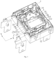
Fig. 1 is a perspective view of a magnetic latching relay according to some embodiments of the present disclosure. -
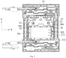
Fig. 2 is a top view of the magnetic latching relay according to some embodiments of the present disclosure as shown inFig. 1 . -
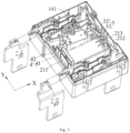
Fig. 3 is a perspective view of the magnetic latching relay according to some embodiments of the present disclosure, with the fixing frame removed. -
Fig. 4 is a perspective view of a base according to some embodiments of the present disclosure. -
Fig. 5 is another perspective view of a base according to some embodiments of the present disclosure. -
Fig. 6 is another perspective view of a base according to some embodiments of the present disclosure. -
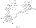
Fig. 7 is a perspective view of a fixing frame according to some embodiments of the present disclosure. - The reference numbers are listed as follows:
- 1. base
- 11. first sidewall
111. first slot
12. second sidewall - 13. third sidewall
131. second slot - 14. fourth sidewall
141. mounting hole - 15. first mounting bracket
- 151. first arcuate support
- 152. first limiting part
- 16. second mounting bracket
- 161. second arcuate support
- 162. second limiting part
- 11. first sidewall
- 2. coil assembly
- 21. bobbin
- 211. first flange
- 212. second flange
- 213. protruding edge
- 22. coil
- 201. first end
- 202. second end
- 21. bobbin
- 3. fixing frame
- 21. first side
- 32. second side
- 33. first protruding portion
- 34. second protruding portion
- 35. third protruding portion
- 36. fourth protruding portion
- 37. first longitudinal limiting part
- 38. second longitudinal limiting part
- 39. connecting column
- 4. first yoke
- 41. first yoke part
- 42. second yoke part
- 5. second yoke
- 51. third yoke part
- 52. fourth yoke part
- 100. first glue dispensing port
- 200. second glue dispensing port
- S. receiving chamber
- X. transverse direction
- Y. longitudinal direction
- Now, the exemplary implementations will be described more completely with reference to the accompanying drawings. However, the exemplary implementations can be implemented in various forms and should not be construed as limiting the implementations as set forth herein. Instead, these implementations are provided so that the present disclosure will be thorough and complete, and concept of the exemplary implementation will be fully conveyed to a skilled person in the art. Same reference numbers denote the same or similar structures in the figures, and thus the detailed description thereof will be omitted.
- As shown in
Fig. 1 andFig. 2 , the embodiments of the present disclosure provide a magnetic latching relay including a base 1, a coil assembly 2, and a fixingframe 3. - As shown in
Fig. 4 to Fig. 6 , the base 1 has a receiving chamber S, which is sequentially connected to afirst sidewall 11, asecond sidewall 12, and athird sidewall 13. Thefirst sidewall 11 and thethird sidewall 13 are oppositely arranged and respectively extend in a longitudinal direction Y, and thesecond sidewall 12 extends in a transverse direction X. - Specifically, as shown in
Fig. 4 , thefirst sidewall 11, thesecond sidewall 12, and thethird sidewall 13 may be integrally formed by an injection molding process. Thefirst sidewall 11 has a first free end, and thethird sidewall 13 has a second free end. The base 1 may also include afourth sidewall 14 that is arranged opposite to thesecond sidewall 12 and has a certain distance from the first free end of thefirst sidewall 11 and the second free end of thethird sidewall 13, so that a first opening is formed between the first free end of thefirst sidewall 11 and thefourth sidewall 14, and a second opening is formed between the second free end of thethird sidewall 13 and thefourth sidewall 14, that is, the receiving chamber S has two openings on both sides thereof. - It should be noted that "longitudinal direction Y" and "transverse direction X" in the present embodiment are technical terms for expressing directions, and in the embodiments of the present disclosure, a direction in which the
second sidewall 12 extends is defined as the transverse direction X, while a direction in which thefirst sidewall 11 and thethird sidewall 13 extend is defined as the longitudinal direction Y. These two technical terms are merely for the convenience of description and do not have a limiting significance. - As shown in
Fig. 2 , the coil assembly 2 includes afirst end 201 and asecond end 202 opposite to each other, thefirst end 201 is adjacent to thefirst sidewall 11; the coil assembly 2 is arranged in the receiving chamber S in the transverse direction X, with a gap between thefirst end 201 and thefirst sidewall 11. - As shown in
Fig. 1 andFig. 2 , the fixingframe 3 is arranged on the base 1, on a side of the coil assembly 2 away from thesecond sidewall 12. The fixingframe 3 has afirst side 31 close to the coil assembly 2 in the longitudinal direction Y. Thefirst side 31 is in sealed contact with thefirst end 201 of the coil assembly 2, specifically, thefirst side 31 is in sealed contact with thefirst flange 211 of thefirst end 201, the side of the fixingframe 3 facing thefirst sidewall 11 is in sealed contact with thefirst sidewall 11, in this way, a firstglue dispensing port 100 surrounded by thefirst sidewall 11, thesecond sidewall 12, thefirst end 201 of the coil assembly 2, and the fixingframe 3 is formed. - In some embodiments, the
first flange 211 of thefirst end 201 of the coil assembly 2 may be in sealed contact with thesecond sidewall 12, in this way, the firstglue dispensing port 100 is a closed glue dispensing port. - In some embodiments, as shown in
Fig. 4 andFig. 6 , the magnetic latching relay further includes a first mountingbracket 15 that is arranged in the receiving chamber S of the base 1 and extends in the longitudinal direction Y. Thefirst mounting bracket 15 is spaced from thefirst sidewall 11, thefirst end 201 of the coil assembly 2 is arranged on the first mountingbracket 15, and one end of the first mountingbracket 15 is in sealed connection with thesecond sidewall 12, in this way, a closed first glue dispensing port surrounded by thefirst sidewall 11, thesecond sidewall 12, the first mountingbracket 15, thefirst end 201 of the coil assembly 2, and the fixingframe 3 is formed. - As shown in
Fig. 4 andFig. 6 , the first mountingbracket 15 has a firstarcuate support 151, thefirst end 201 of the coil assembly 2 is arranged on the firstarcuate support 151 with an arcuate surface, and thefirst end 201 of the coil assembly 2 is positioned on the arcuate surface. As shown inFig. 6 , one end of the firstarcuate support 151 is in sealed connection with thesecond sidewall 12. - Specifically, as shown in
Fig. 6 , the firstarcuate support 151 of the first mountingbracket 15 includes two sections of the arcuate supports that are opposite to each other in the longitudinal direction Y, the surface of the arcuate support is the arcuate surface. A curvature of the arcuate surface may be equal to or greater than a curvature of acoil 22 of the coil assembly 2, so that the arcuate surface may conform to the surface of thecoil 22 for support. - In some embodiments, as shown in
Fig. 1 , the coil assembly 2 includes abobbin 21 and acoil 22, thebobbin 21 includes a hollow cylindrical body and afirst flange 211 that protrude radially at both ends of the body, and thecoil 22 wound around the outer surface of the body. Here, as shown inFig. 2 , thefirst end 201 of the coil assembly 2 may be understood as a first end portion, which includes the coil 22 (i.e., straight lines as enclosed by dashed lines inFig. 2 ) supported by the arcuate surface of the firstarcuate support 151 and thefirst flange 211 at thefirst end 201, i.e., the portion from thefirst flange 211 to the dashed lines represents thefirst end 201. When the coil assembly 2 is arranged on the first mountingbracket 15, thefirst flange 211 of thefirst end 201 is arranged between thefirst sidewall 11 and the first mountingbracket 15, and there is still a first distance between thefirst flange 211 of thefirst end 201 and thefirst sidewall 11. - In some embodiments, as shown in
Fig. 6 , one end of the firstarcuate support 151 is in sealed connection with thesecond sidewall 12, wherein the one end of firstarcuate support 151 refers to one end of the firstarcuate support 151 that is closer to thesecond sidewall 12 in the longitudinal direction Y. The one end of the firstarcuate support 151 is in sealed connection with thesecond sidewall 12, it is possible that the firstarcuate support 151 and thesecond sidewall 12 are formed by integrally injection molding or the one end of the firstarcuate support 151 is in sealed connection with thesecond sidewall 12 by bonding, without any special limitation herein. Since one end of the firstarcuate support 151 is in sealed connection with thesecond sidewall 12, when glue is dispensed between thefirst end 201 of the coil assembly 2 and thefirst sidewall 11, the firstarcuate support 151 acts as a barrier to flowing of the glue, preventing it from flowing into other areas of the relay. - In some embodiments, as shown in
Fig. 4 andFig. 6 , the first mountingbracket 15 also has a first limitingpart 152 that is in sealed connection with the other end of the firstarcuate support 151 and is spaced from thefirst sidewall 11. - As shown in
Fig. 4 andFig. 6 , the other end of the firstarcuate support 151 refers to one end that is opposite to the end of the firstarcuate support 151 in the longitudinal direction Y. The first limitingpart 152 is in sealed connection with the other end. In some embodiments, the first limitingpart 152 and the other end of the firstarcuate support 151 are integrally formed by injection molding, or the first limitingpart 152 is in sealed connection with the other end of the firstarcuate support 151 by bonding. In some embodiments, the first limitingpart 152 is spaced from thefirst sidewall 11 and has a height equal to thefirst sidewall 11. Due to the arrangement of the first limitingpart 152, when thefirst end 201 of the coil assembly 2 is arranged on the firstarcuate support 151, the first limitingpart 152 and thesecond sidewall 12 are used to limit on both sides of the coil assembly 2, preventing it from swaying in the longitudinal direction Y and ensuring the stability of the coil assembly 2. At the same time, the first limitingpart 152 also serves to reinforce the firstarcuate support 151, thereby prolonging service life of the firstarcuate support 151. - In some embodiments, a first protruding
portion 33 is arranged on one side of the fixingframe 3 facing thefirst sidewall 11 and protrudes towards thefirst sidewall 11, and the first protrudingportion 33 is in sealed contact with thefirst sidewall 11. - As shown in
Fig. 2 , thefirst side 31 of the fixingframe 3 is a side of the two sides of the fixingframe 3 distributed in the Longitudinal direction Y, close to the coil assembly 2. Thefirst side 31 is in sealed contact with the side surface of thefirst flange 211 of the coil assembly 2. The fixingframe 3 has asecond side 32 opposite to thefirst side 31. There is a connecting column 39 towards the base 1 (as shown inFig. 7 ) on thesecond side 32 of the fixingframe 3. As shown inFig. 3 to Fig. 6 , there is a mountinghole 141 corresponding to the connecting column 39 on thefourth sidewall 14. By inserting the connecting column 39 into the corresponding mountinghole 141, the fixingframe 3 is arranged on the base 1. As shown inFig. 2 , a firstglue dispensing port 100 surrounded by the fixingframe 3, thefirst sidewall 11, thesecond sidewall 12, the firstarcuate support 151 of the first mountingbracket 15, and thefirst flange 211 of thefirst end 201 of the coil assembly 2 is formed, and the firstglue dispensing port 100 is closed (as enclosed by the dashed lines inFig. 2 ). Below the firstglue dispensing port 100, there is a first glue dispensing slot formed by thefirst sidewall 11, thesecond sidewall 12, the firstarcuate support 151 of the first mountingbracket 15, thefirst flange 211 of thefirst end 201 of the coil assembly 2, and the first limitingpart 152, and the first glue dispensing slot is not closed but has gaps. - During dispensing the glue, the glue is relatively thick and has low fluidity. When dispensing the glue in the first
glue dispensing port 100, it can be ensured that the glue does not spill over due to a closed inner profile of the firstglue dispensing port 100. As the glue flows downward slowly, the gaps in the first glue dispensing slot can facilitate the expulsion of air from the glue, and improve a bonding effect of the glue. It should be noted that due to the high viscosity and the low fluidity of the glue, and the glue dispensing range in the firstglue dispensing port 100 is determined, even if the first glue dispensing slot is not closed, the glue will adhere to the corresponding components after entering the first glue dispensing slot and will not spill over to other areas. - In some embodiments, as shown in
Fig. 2 , a second protrudingportion 34 that protrudes towards thefirst end 201 of the coil assembly 2 is arranged on thefirst side 31 of the fixingframe 3, and the second protrudingportion 34 is in sealed contact with thefirst end 201 of the coil assembly 2 and the other end of the first mountingbracket 15, respectively. - Specifically, as shown in
Fig. 2 , the second protrudingportion 34 protrudes towards a direction close to the coil assembly 2 with respect to thefirst side 31 and abuts against one side of thefirst flange 211 on thefirst end 201 of the coil assembly 2, and the bottom surface of the second protruding portion 34 (the surface facing one side of the base 1) covers the first limitingpart 152 of the first mountingbracket 15. Therefore, the first limitingpart 152 is in sealed contact with the fixingframe 3, and during the oven curing process after dispensing, even if the fluidity of the adhesive increases, it will not flow through the first mountingbracket 15 to other areas. - In some embodiments, as shown in
Fig. 3 , the magnetic latching relay further includes afirst yoke 4, which includes afirst yoke part 41 and asecond yoke part 42 connected in an L-shape. Thefirst yoke part 41 is arranged between thefirst end 201 of the coil assembly 2 and thefirst sidewall 11 and is fixed to thefirst sidewall 11. Thesecond yoke part 42 faces the fixingframe 3. As shown inFig. 7 , the fixingframe 3 includes a first longitudinal limitingpart 37 that clamps to thesecond yoke part 42 in the longitudinal direction Y. - As shown in
Fig. 3 , thefirst yoke part 41 of thefirst yoke 4 is arranged in the distance between thefirst end 201 of the coil assembly 2 and thefirst sidewall 11 and is fixed to thefirst sidewall 11. As shown inFig. 4 , there is afirst slot 111 on thefirst sidewall 11, and thefirst yoke part 41 has a first protrusion (not shown) that engages with thefirst slot 111, to allow the first protrusion clamped in thefirst slot 111, so as to fix thefirst yoke part 41 to thefirst sidewall 11. Since thefirst yoke part 41 occupies a space between thefirst sidewall 11 and thefirst end 201 of the coil assembly 2, after dispensing the glue, the glue will flow downward along thefirst yoke part 41, thefirst sidewall 11, thesecond sidewall 12, thefirst end 201 of the coil assembly 2, and the first mountingbracket 15 within the firstglue dispensing port 100. Due to the high viscosity of the glue, it will not spill over, and there is the gap between the aforementioned components, it facilitates expelling the air from the glue, to make the bonding of the components such as theyoke 4 more secure. After dispensing the glue, when it is placed in the oven for curing, the viscosity of the glue will decrease and its fluidity will increase as the temperature rises, allowing the glue to flow fully into all the components within the first glue dispensing slot and further expelling the air from the glue to make the bonding of the components more secure. Since the gap between the aforementioned components is small, the resulting glue area is large, which can prevent the glue from spilling over. - As shown in
Fig. 3 , thesecond yoke part 42 is bent towards the direction close to thethird sidewall 13. The first longitudinal limitingpart 37 of the fixingframe 3 clamps to thesecond yoke part 42, which can prevent thefixing frame 3 from being directly plugged into the base 1, i.e., prevent the arrangement for corresponding installation holes on the base 1, to simplify the structure of the base 1 and allow the fixingframe 3 to be installed quickly and accurately. - In some embodiments, as shown in
Fig. 2 , thesecond end 202 of the coil assembly 2 is adjacent to thethird sidewall 13, and thefirst side 31 of the fixingframe 3 is in sealed contact with thesecond end 202 of the coil assembly 2. - As shown in
Fig. 2 , thesecond end 202 of the coil assembly 2 may be interpreted as a second end portion, which includes acoil 22 partially wound on a main body of the bobbin 21 (as shown in the straight lines enclosed by the dashed lines inFig. 2 ) and asecond flange 212 of thebobbin 21 at thesecond end 202. Herein, a second distance between thesecond end 202 of the coil assembly 2 and thethird sidewall 13 is a distance between thesecond flange 212 of thesecond end 202 and thethird sidewall 13. Thefirst side 31 of the fixingframe 3 abuts against the side surface of thesecond flange 212 of the coil assembly 2, so that thefirst side 31 of the fixingframe 3 is sealed contact with thesecond end 202 of the coil assembly 2. - In some embodiments, as shown in
Fig. 1 andFig. 2 , The top of thesecond end 202 of the coil component 2 has a protrudingedge 213 that protrudes towards thethird sidewall 13, and the protrudingedge 213 is in sealing contact with the top of thethird sidewall 13. - As shown in
Fig. 1 andFig. 2 , the protrudingedge 213 protrudes from the top of thesecond flange 212 at thesecond end 202 of the coil component 2 towards thethird sidewall 13. That is, the protrudingedge 213 is a protruding portion at the top of thesecond flange 212, there is a distance between thesecond flange 212 and thethird sidewall 13 under the protrudingedge 213. The protrudingedge 213 is used for connecting terminals, as shown inFig. 1 , three connecting terminals are arranged on the protrudingedge 213. The protrudingedge 213 may abut against the top of thethird sidewall 13, so that the protrudingedge 213 is in sealed contact with the top of thethird sidewall 13. - In some embodiments, as shown in
Fig. 1 andFig. 2 , the fixingframe 3 has a third protrudingportion 35 that protrudes towards thethird sidewall 13, and the third protrudingportion 35 is in sealed contact with thethird sidewall 13, in this way, a closed secondglue dispensing port 200 surrounded by thethird sidewall 13, thesecond end 202 of the coil assembly 2, and the fixingframe 3 is formed. - Specifically, as shown in
Fig. 1 andFig. 2 , the fixingframe 3 has a third protrudingportion 35 that protrudes towards thethird sidewall 13, and the third protrudingportion 35 is in sealed contact with thethird sidewall 13, for example, the third protrudingportion 35 abuts against the second free end of thethird sidewall 13. As shown inFig. 2 , a secondglue dispensing port 200 surrounded by thethird sidewall 13, the protrudingedge 213 of thesecond end 202 of the coil assembly 2, thefirst flange 211, and the fixingframe 3 is formed, and the secondglue dispensing port 200 is closed (as enclosed by the dashed lines inFig. 2 ). When dispensing the glue, the glue is relatively thick and has low fluidity, and as dispensing the glue in the closed secondglue dispensing port 200, it is ensured that the glue does not spill over due to the closed profile of the secondglue dispensing port 200. - In some embodiments, as shown in
Fig. 1 andFig. 2 , thefirst side 31 of the fixingframe 3 has a fourth protrudingportion 36 that protrudes towards the coil assembly 2, and the fourth protrudingportion 36 is in sealed contact with thesecond end 202 of the coil assembly 2. - As shown in
Fig. 1 andFig. 2 , the fourth protrudingportion 36 protrudes towards the coil assembly 2 with respect to thefirst side 31 of the fixingframe 3 and abuts against one side of thesecond flange 212 of thesecond end 202 of the coil assembly 2, so that the fourth protrudingportion 36 is in sealed contact with thesecond end 202 of the coil assembly 2. - In some embodiments, as shown in
Fig. 4 to Fig. 6 , the base 1 further has asecond mounting bracket 16 that extends in the longitudinal direction Y, the second mountingbracket 16 is arranged in the receiving chamber S and is spaced from thethird sidewall 13 in the transverse direction X, one end of the second mountingbracket 16 is in sealed connection with thesecond sidewall 12, and thesecond end 202 of the coil assembly 2 is arranged on the second mountingbracket 16. - In some embodiments, as shown in
Fig. 6 , the second mountingbracket 16 has a secondarcuate support 161 with an arcuate surface, thesecond end 202 of the coil assembly 2 is arranged on the arcuate surface, and one end of the secondarcuate support 161 is in sealed connection with thesecond sidewall 12. - Specifically, as shown in
Fig. 5 andFig. 6 , the second mountingbracket 16 has a secondarcuate support 161 that includes two sections of the arcuate support portions, which are opposite to each other in the longitudinal direction Y, the surfaces of the arcuate support sections are arcuate surfaces. A curvature of the arcuate surface may be equal to or greater than a curvature of thecoil 22 of the coil assembly 2, so that the arcuate surface may conform to the surface of thecoil 22 for support. Therefore, thesecond end 202 of the coil assembly 2 includes thecoil 22 supported by the arcuate surface of the secondarcuate support 161, thecoil 22 is wound on the bobbin 21 (as shown by the straight lines enclosed by the dashed lines inFig. 2 ) and thesecond flange 212 of thesecond end 202, that is, thesecond end 202 is the portion from thesecond flange 212 to the dashed lines on thecoil 22. When the coil assembly 2 is arranged on the second mountingbracket 16, thesecond flange 212 of thesecond end 202 of the coil assembly 2 is arranged between thefirst sidewall 11 and the second mountingbracket 16, and there is still a second gap between thefirst flange 211 of thesecond end 202 and thethird sidewall 13. - As shown in
Fig. 6 , one end of the second mountingbracket 16 is in sealed connection with thesecond sidewall 12. Herein, one end of the second mountingbracket 16 refers to one of the secondarcuate support 161 that is closer to thesecond sidewall 12 in the longitudinal direction Y. The secondarcuate support 161 may be integrally injection molded with thesecond sidewall 12, or one end of the secondarcuate support 161 is in sealed connection with thesecond sidewall 12 by bonding, without any special limitation herein. Since one end of the secondarcuate support 161 is in sealed connection with thesecond sidewall 12, when dispensing the glue into the secondglue dispensing port 200, the secondarcuate support 161 acts as a barrier to the flowing of the glue, to prevent it from flowing into other areas of the relay. - In some embodiments, as shown in
Fig. 5 , the secondarcuate support 161 further has a second limitingpart 162, which is in sealed connection with the other end of the secondarcuate support 161 and is spaced from thethird sidewall 13 in the transverse direction X. The second limitingpart 162 may have the same structure and function with the first limitingpart 152, which is not described in detail herein. - In some embodiments, the bottom surface (the surface facing one side of the base 1) of the fourth protruding
portion 36 of the fixingframe 3 covers the second limitingpart 162. Therefore, the second limitingpart 162 is in sealed contact with the fixingframe 3, and during the oven curing process after dispensing, even if the fluidity of the adhesive increases, it will not flow through the second mountingbracket 16 to other areas. - Through the above arrangement, under the second
glue dispensing port 200, there is a second glue dispensing slot formed by thethird sidewall 13, thesecond sidewall 12, the secondarcuate support 161 of the second mountingbracket 16, thesecond end 202 of the coil assembly 2, and the second limitingpart 162. The second glue dispensing slot is not closed but has a gap. - During dispensing the glue, the glue is relatively thick, and when the glue is dripped from the second
glue dispensing port 200, it flows downward slowly. Since the second glue dispensing slot has the gap, it facilitates expelling the air from the glue, and improving the bonding effect of the glue. Due to the high viscosity and low fluidity of the glue, and after dispensing the glue through the secondglue dispensing port 200, even if the second glue dispensing slot is not closed, the glue will adhere to the corresponding components after entering the second glue dispensing slot and will not spill over to other areas to make the bonding of the components more secure. - In some embodiments, as shown in
Fig. 3 , the magnetic latching relay further includes a second yoke 5, which includes athird yoke part 51 and a fourth yoke part 52 connected in an L-shape. Thethird yoke part 51 is arranged between thesecond end 202 of the coil assembly 2 and thethird sidewall 13 and is fixed to thethird sidewall 13. The fourth yoke part 52 faces the fixingframe 3. As shown inFig. 7 , the fixingframe 3 includes a second longitudinal limitingpart 38 that clamps to the fourth yoke part 52 in the longitudinal direction Y. - As shown in
Fig. 3 , thethird yoke part 51 of the second yoke 5 is arranged in the second distance between thesecond end 202 of the coil assembly 2 and thethird sidewall 13 and is fixed to thethird sidewall 13. As shown inFig. 5 , there is asecond slot 131 on thethird sidewall 13, and thethird yoke part 51 has a second protrusion (not shown) that engages with thesecond slot 131, and the second protrusion is clamped in thesecond slot 131, so that thethird yoke part 51 is fixed to thethird sidewall 13. Since thethird yoke part 51 occupies a space between thethird sidewall 13 and thesecond end 202 of the coil assembly 2, after dispensing the glue, the glue will flow downward along thethird yoke part 51, thethird sidewall 13, thesecond sidewall 12, thesecond end 202 of the coil assembly 2, and the second mountingbracket 16 within the secondglue dispensing port 200. Due to the high viscosity of the glue, it will not spill over, and there is the gap between the aforementioned components, it facilitates expelling the air from the glue, to make the bonding of the components such as the yoke more secure. After dispensing the glue, when it is placed in the oven for curing, the viscosity of the glue will decrease and its fluidity will increase as the temperature rises, allowing the glue to flow fully into all the components within the first glue dispensing slot and further expelling the air from the glue to make the bonding of the components more secure. Since the gap between the aforementioned components is small, the resulting glue area is large, which can prevent the glue from spilling over. - As shown in
Fig. 3 , the fourth yoke part 52 is bent towards the direction close to thefirst sidewall 11. The second longitudinal limitingpart 38 of the fixingframe 3 clamps to the fourth yoke part 52, which can prevent thefixing frame 3 from being directly plugged into the base 1, simplify the structure of the base 1, and allow the fixingframe 3 to be installed quickly and accurately. - It can be understood that the various examples/embodiments provided by the present disclosure can be combined with each other without contradiction, and detailed examples are not provided herein.
- In the embodiments of the present disclosure, the terms "first", "second", "third" are used for descriptive purposes only and should not be understood as indicating or implying relative importance; the term "a plurality of' refers to two or more, unless there is a clear definition otherwise. The terms such as "installation", "connected", "connection", "fixed" should be understood in a broad sense. For example, "connection" can be a fixed connection, or a removable connection, or an integral connection; "connected" can be directly connected, or indirectly connected through an intermediary medium. For the ordinary skilled person in the art, the specific meanings of these terms in the embodiments of the invention can be understood based on the specific circumstances.
- In the description of the embodiments of the present disclosure, it should be understood that the terms "upper", "lower", "left", "right", "front", and "rear" indicate a direction or position based on the orientation or position shown in the accompanying drawings. These terms are used only to facilitate the description of the embodiment and to simplify the description, and are not intended to indicate or imply that the device or unit referred to must have a specific direction, be constructed and operated in a specific orientation. Therefore, these terms should not be construed as limiting the embodiments of the invention.
- In the description of this specification, terms such as "an embodiment," "some embodiments," "a specific embodiment" refer to the specific features, structures, materials, or characteristics described in conjunction with the embodiment or example being included in at least one embodiment or example of the invention. In this specification, the illustrative terms do not necessarily refer to the same embodiment or example. Moreover, the specific features, structures, materials, or characteristics described may be suitably combined in any one or more of the embodiments or examples.
- The above description is merely a preferred embodiment of the present disclosure and is not intended to limit the embodiment. For the person skilled in the art, the present disclosure may be subject to various changes and modifications. Any modifications, equivalent substitutions, improvements, and the like made within the spirit and principles of the embodiments of the present disclosure should be included within the scope of protection of the embodiments of the present disclosure.
Claims (13)
- A magnetic latching relay, comprising:a base (1), with a receiving chamber (S), the receiving chamber (S) having a first sidewall (11) extending in a longitudinal direction (Y) and a second sidewall (12) extending in a transverse direction (X), the first sidewall (11) and the second sidewall (12) being connected;a coil assembly (2), arranged in the receiving chamber (S) in the transverse direction (X), and the coil assembly (2) having a first end (201) adjacent to the first sidewall (11);a fixing frame (3), arranged on the base (1) and located on a side of the coil assembly (2) away from the second sidewall (12), the fixing frame (3) having a first side (21) close to the coil assembly (2) in the longitudinal direction (Y), the first side (21) being in sealed contact with a first end (201) of the coil assembly (2), and a side of the fixing frame (3) facing the first sidewall (11) being in sealed contact with the first sidewall (11), thereby forming a first glue dispensing port (100) surrounded by the first sidewall (11), the second sidewall (12), the first end (201) of the coil assembly (2), and the fixing frame (3).
- The magnetic latching relay according to claim 1, further comprising:
a first mounting bracket (15), arranged in the receiving chamber (S) of the base (1) and extending in the longitudinal direction (Y), the first mounting bracket (15) being spaced from the first sidewall (11), the first end (201) of the coil assembly (2) being arranged on the first mounting bracket (15), and one end of the first mounting bracket (15) being in sealed connection with the second sidewall (12), thereby forming a closed first glue dispensing port (100) surrounded by the first sidewall (11), the second sidewall (12), the first mounting bracket (15), the first end (201) of the coil assembly (2), and the fixing frame (3). - The magnetic latching relay according to claim 2, wherein the side of the fixing frame (3) facing the first sidewall (11) has a first protruding portion (33) protruding towards the first sidewall (11), the first protruding portion (33) is in sealed contact with the first sidewall (11), and the first side (21) of the fixing frame (3) has a second protruding portion (34) protruding towards the first end (201) of the coil assembly (2), the second protruding portion (34) is in sealed contact with the first end (201) of the coil assembly (2) and the other end of the first mounting bracket (15).
- The magnetic latching relay according to claim 2, wherein the first mounting bracket (15) has a first arcuate support (151) with an arcuate surface, the first end (201) of the coil assembly (2) is located on the arcuate surface; one end of the first arcuate support (151) is in sealed connection with the second sidewall (12).
- The magnetic latching relay according to claim 4, wherein the first mounting bracket (15) further has a first limiting part (152) that is in sealed connection with the other end of the first arcuate support (151) and is spaced from the first sidewall (11).
- The magnetic latching relay according to claim 1, further comprising:
a first yoke (4), comprising a first yoke (4) part (41) and a second yoke (5) part (42), the first yoke (4) part (41) and the second yoke (5) part (42) being connected in an L-shape, the first yoke (4) part (41) being located between the first end (201) of the coil assembly (2) and the first sidewall (11) and being fixedly arranged on the first sidewall (11), the second yoke (5) part (42) facing the fixing frame (3); the fixing frame (3) comprising a first longitudinal limiting part (37), the first longitudinal limiting part (37) being clamped to the second yoke (5) part (42) in a longitudinal direction (Y). - The magnetic latching relay according to any one of claims 1 to 6, wherein the coil assembly (2) further comprises a second end (202) opposite to the first end (201), the receiving chamber (S) further has a third sidewall (13) extending in the longitudinal direction (Y), the third sidewall (13) is connected with the second sidewall (12) and being arranged opposite to the first sidewall (11), the second end (202) of the coil assembly (2) is adjacent to the third sidewall (13), and the first side (21) of the fixing frame (3) is in sealed contact with the second end (202) of the coil assembly (2).
- The magnetic latching relay according to claim 7, wherein a top of the second end (202) of the coil assembly (2) has a flange protruding towards the third sidewall (13), the flange is in sealed contact with the top of the third sidewall (13).
- The magnetic latching relay according to claim 8, wherein the fixing frame (3) has a third protruding portion (35) protruding towards the third sidewall (13), the third protruding portion (35) is in sealed contact with the third sidewall (13), thereby forming a closed second glue dispensing port (200) surrounded by the third sidewall (13), the second end (202) of the coil assembly (2), and the fixing frame (3).
- The magnetic latching relay according to claim 7, wherein the first side (21) of the fixing frame (3) has a fourth protruding portion (36) protruding towards the coil assembly (2), and the fourth protruding portion (36) is in sealed contact with the second end (202) of the coil assembly (2).
- The magnetic latching relay according to claim 7, wherein the base (1) further has a second mounting bracket (16) extending in the longitudinal direction (Y), the second mounting bracket (16) is arranged in the receiving chamber (S) and is spaced from the third sidewall (13), one end of the second mounting bracket (16) is in sealed connection with the second sidewall (12), and the second end (202) of the coil assembly (2) is arranged on the second mounting bracket (16).
- The magnetic latching relay according to claim 11, wherein the second mounting bracket (16) has a second arcuate support (161) with an arcuate surface, the second end (202) of the coil assembly (2) is located on the arcuate surface, and one end of the second arcuate support (161) is in sealed connection with the second sidewall (12).
- The magnetic latching relay according to claim 7, further comprising:
a second yoke (5), comprising a third yoke part (51) and a fourth yoke part (52), the third yoke part (51) and the fourth yoke part (52) being connected in an L-shape, the third yoke part (51) being arranged between the second end (202) of the coil assembly (2) and the third sidewall (13) and being fixedly arranged on the third sidewall (13), the fourth yoke part (52) facing the fixing frame (3); the fixing frame (3) comprising a second longitudinal limiting part (38), the second longitudinal limiting part (38) being clamped to the fourth yoke part (52) in the longitudinal direction (Y).
Applications Claiming Priority (1)
| Application Number | Priority Date | Filing Date | Title |
|---|---|---|---|
| CN202321210069.8U CN220041734U (en) | 2023-05-18 | 2023-05-18 | Magnetic latching relay |
Publications (2)
| Publication Number | Publication Date |
|---|---|
| EP4465330A1 true EP4465330A1 (en) | 2024-11-20 |
| EP4465330B1 EP4465330B1 (en) | 2025-11-19 |
Family
ID=88741593
Family Applications (1)
| Application Number | Title | Priority Date | Filing Date |
|---|---|---|---|
| EP24176665.8A Active EP4465330B1 (en) | 2023-05-18 | 2024-05-17 | Magnetic latching relay |
Country Status (7)
| Country | Link |
|---|---|
| US (1) | US20240387130A1 (en) |
| EP (1) | EP4465330B1 (en) |
| JP (1) | JP3247509U (en) |
| KR (1) | KR200499570Y1 (en) |
| CN (1) | CN220041734U (en) |
| ES (1) | ES3057735T3 (en) |
| PL (1) | PL4465330T3 (en) |
Citations (2)
| Publication number | Priority date | Publication date | Assignee | Title |
|---|---|---|---|---|
| CN206877914U (en) * | 2017-05-09 | 2018-01-12 | 浙江正泰电器股份有限公司 | Magnetic latching relay |
| CN209708908U (en) * | 2019-01-24 | 2019-11-29 | 浙江正泰电器股份有限公司 | Magnetic latching relay |
Family Cites Families (4)
| Publication number | Priority date | Publication date | Assignee | Title |
|---|---|---|---|---|
| JPH01220323A (en) * | 1988-02-19 | 1989-09-04 | Taiko Denki Seisakusho:Kk | Relay |
| JP4476072B2 (en) * | 2004-08-20 | 2010-06-09 | 富士通コンポーネント株式会社 | Electromagnetic relay |
| JP5914065B2 (en) * | 2012-03-12 | 2016-05-11 | 富士電機機器制御株式会社 | Switch |
| DE112020005406T5 (en) * | 2019-11-01 | 2022-08-18 | Xiamen Hongfa Automotive Electronics Co., Ltd. | ELECTROMAGNETIC RELAY |
-
2023
- 2023-05-18 CN CN202321210069.8U patent/CN220041734U/en active Active
-
2024
- 2024-05-16 US US18/666,360 patent/US20240387130A1/en active Pending
- 2024-05-17 KR KR2020240000880U patent/KR200499570Y1/en active Active
- 2024-05-17 ES ES24176665T patent/ES3057735T3/en active Active
- 2024-05-17 EP EP24176665.8A patent/EP4465330B1/en active Active
- 2024-05-17 JP JP2024001584U patent/JP3247509U/en active Active
- 2024-05-17 PL PL24176665.8T patent/PL4465330T3/en unknown
Patent Citations (2)
| Publication number | Priority date | Publication date | Assignee | Title |
|---|---|---|---|---|
| CN206877914U (en) * | 2017-05-09 | 2018-01-12 | 浙江正泰电器股份有限公司 | Magnetic latching relay |
| CN209708908U (en) * | 2019-01-24 | 2019-11-29 | 浙江正泰电器股份有限公司 | Magnetic latching relay |
Also Published As
| Publication number | Publication date |
|---|---|
| PL4465330T3 (en) | 2026-02-23 |
| CN220041734U (en) | 2023-11-17 |
| KR200499570Y1 (en) | 2025-09-09 |
| KR20240001915U (en) | 2024-11-26 |
| US20240387130A1 (en) | 2024-11-21 |
| ES3057735T3 (en) | 2026-03-04 |
| JP3247509U (en) | 2024-07-17 |
| EP4465330B1 (en) | 2025-11-19 |
Similar Documents
| Publication | Publication Date | Title |
|---|---|---|
| US5800183A (en) | Sealed socket assembly for a plug-in lamp and a method for assembling same | |
| US6835090B1 (en) | Sealed housing assembly | |
| US6964575B1 (en) | Sealed electronic module with seal-in-place connector header | |
| US7085138B2 (en) | Electronic control unit, in particular a speed control unit for an electric fan, and a process for its fabrication | |
| US9952086B2 (en) | Magnetic float liquid level detector with vertically reversible attachment | |
| EP4465330B1 (en) | Magnetic latching relay | |
| US4473730A (en) | Liquid-level detection switch | |
| US20220392725A1 (en) | Electromagnetic relay | |
| WO2026041056A1 (en) | Relay | |
| CN222320131U (en) | Relay device | |
| KR20000023651A (en) | Electromagnetic relay and process for producing the same | |
| US4554522A (en) | Electromagnetic relay | |
| CN110001542B (en) | Whole vehicle controller | |
| CN218039047U (en) | Large-current magnetic latching relay with auxiliary switch | |
| WO2024045944A1 (en) | Reed relay and manufacturing method therefor | |
| US5771149A (en) | Capacitor device | |
| KR102913975B1 (en) | fuse | |
| US6476699B1 (en) | Reed switch unit | |
| JP7300897B2 (en) | case mold type capacitor | |
| JPS59169019A (en) | Electromagnetic relay | |
| JP2002310224A (en) | Anti-vibration device | |
| CN219591326U (en) | Armature component and electromagnetic relay with high creepage performance | |
| JP3702490B2 (en) | Discharge lamp ballast | |
| CN121593970A (en) | Fluid control device | |
| CN215911651U (en) | Connecting device and connector |
Legal Events
| Date | Code | Title | Description |
|---|---|---|---|
| PUAI | Public reference made under article 153(3) epc to a published international application that has entered the european phase |
Free format text: ORIGINAL CODE: 0009012 |
|
| STAA | Information on the status of an ep patent application or granted ep patent |
Free format text: STATUS: REQUEST FOR EXAMINATION WAS MADE |
|
| 17P | Request for examination filed |
Effective date: 20240517 |
|
| AK | Designated contracting states |
Kind code of ref document: A1 Designated state(s): AL AT BE BG CH CY CZ DE DK EE ES FI FR GB GR HR HU IE IS IT LI LT LU LV MC ME MK MT NL NO PL PT RO RS SE SI SK SM TR |
|
| GRAP | Despatch of communication of intention to grant a patent |
Free format text: ORIGINAL CODE: EPIDOSNIGR1 |
|
| STAA | Information on the status of an ep patent application or granted ep patent |
Free format text: STATUS: GRANT OF PATENT IS INTENDED |
|
| RIC1 | Information provided on ipc code assigned before grant |
Ipc: H01H 50/04 20060101AFI20250701BHEP Ipc: H01H 51/22 20060101ALI20250701BHEP Ipc: H01H 50/64 20060101ALN20250701BHEP |
|
| INTG | Intention to grant announced |
Effective date: 20250717 |
|
| GRAS | Grant fee paid |
Free format text: ORIGINAL CODE: EPIDOSNIGR3 |
|
| GRAA | (expected) grant |
Free format text: ORIGINAL CODE: 0009210 |
|
| STAA | Information on the status of an ep patent application or granted ep patent |
Free format text: STATUS: THE PATENT HAS BEEN GRANTED |
|
| AK | Designated contracting states |
Kind code of ref document: B1 Designated state(s): AL AT BE BG CH CY CZ DE DK EE ES FI FR GB GR HR HU IE IS IT LI LT LU LV MC ME MK MT NL NO PL PT RO RS SE SI SK SM TR |
|
| REG | Reference to a national code |
Ref country code: CH Ref legal event code: F10 Free format text: ST27 STATUS EVENT CODE: U-0-0-F10-F00 (AS PROVIDED BY THE NATIONAL OFFICE) Effective date: 20251119 Ref country code: GB Ref legal event code: FG4D |
|
| REG | Reference to a national code |
Ref country code: DE Ref legal event code: R096 Ref document number: 602024001304 Country of ref document: DE |
|
| REG | Reference to a national code |
Ref country code: SE Ref legal event code: TRGR |
|
| REG | Reference to a national code |
Ref country code: IE Ref legal event code: FG4D |
|
| REG | Reference to a national code |
Ref country code: ES Ref legal event code: FG2A Ref document number: 3057735 Country of ref document: ES Kind code of ref document: T3 Effective date: 20260304 |
|
| REG | Reference to a national code |
Ref country code: NL Ref legal event code: MP Effective date: 20251119 |
|
| REG | Reference to a national code |
Ref country code: LT Ref legal event code: MG9D |
|
| PG25 | Lapsed in a contracting state [announced via postgrant information from national office to epo] |
Ref country code: NO Free format text: LAPSE BECAUSE OF FAILURE TO SUBMIT A TRANSLATION OF THE DESCRIPTION OR TO PAY THE FEE WITHIN THE PRESCRIBED TIME-LIMIT Effective date: 20260219 |
|
| PG25 | Lapsed in a contracting state [announced via postgrant information from national office to epo] |
Ref country code: HR Free format text: LAPSE BECAUSE OF FAILURE TO SUBMIT A TRANSLATION OF THE DESCRIPTION OR TO PAY THE FEE WITHIN THE PRESCRIBED TIME-LIMIT Effective date: 20251119 Ref country code: AT Free format text: LAPSE BECAUSE OF FAILURE TO SUBMIT A TRANSLATION OF THE DESCRIPTION OR TO PAY THE FEE WITHIN THE PRESCRIBED TIME-LIMIT Effective date: 20251119 Ref country code: FI Free format text: LAPSE BECAUSE OF FAILURE TO SUBMIT A TRANSLATION OF THE DESCRIPTION OR TO PAY THE FEE WITHIN THE PRESCRIBED TIME-LIMIT Effective date: 20251119 |
|
| REG | Reference to a national code |
Ref country code: AT Ref legal event code: MK05 Ref document number: 1859625 Country of ref document: AT Kind code of ref document: T Effective date: 20251119 |
|
| PG25 | Lapsed in a contracting state [announced via postgrant information from national office to epo] |
Ref country code: NL Free format text: LAPSE BECAUSE OF FAILURE TO SUBMIT A TRANSLATION OF THE DESCRIPTION OR TO PAY THE FEE WITHIN THE PRESCRIBED TIME-LIMIT Effective date: 20251119 |
|
| PG25 | Lapsed in a contracting state [announced via postgrant information from national office to epo] |
Ref country code: RS Free format text: LAPSE BECAUSE OF FAILURE TO SUBMIT A TRANSLATION OF THE DESCRIPTION OR TO PAY THE FEE WITHIN THE PRESCRIBED TIME-LIMIT Effective date: 20260219 |
|
| PG25 | Lapsed in a contracting state [announced via postgrant information from national office to epo] |
Ref country code: IS Free format text: LAPSE BECAUSE OF FAILURE TO SUBMIT A TRANSLATION OF THE DESCRIPTION OR TO PAY THE FEE WITHIN THE PRESCRIBED TIME-LIMIT Effective date: 20260319 |
|
| PG25 | Lapsed in a contracting state [announced via postgrant information from national office to epo] |
Ref country code: PT Free format text: LAPSE BECAUSE OF FAILURE TO SUBMIT A TRANSLATION OF THE DESCRIPTION OR TO PAY THE FEE WITHIN THE PRESCRIBED TIME-LIMIT Effective date: 20260319 |
|
| PG25 | Lapsed in a contracting state [announced via postgrant information from national office to epo] |
Ref country code: LV Free format text: LAPSE BECAUSE OF FAILURE TO SUBMIT A TRANSLATION OF THE DESCRIPTION OR TO PAY THE FEE WITHIN THE PRESCRIBED TIME-LIMIT Effective date: 20251119 |
|
| PG25 | Lapsed in a contracting state [announced via postgrant information from national office to epo] |
Ref country code: BG Free format text: LAPSE BECAUSE OF FAILURE TO SUBMIT A TRANSLATION OF THE DESCRIPTION OR TO PAY THE FEE WITHIN THE PRESCRIBED TIME-LIMIT Effective date: 20251119 |