EP4465315A1 - Method to detect a size change in an energy storage device - Google Patents
Method to detect a size change in an energy storage device Download PDFInfo
- Publication number
- EP4465315A1 EP4465315A1 EP23173633.1A EP23173633A EP4465315A1 EP 4465315 A1 EP4465315 A1 EP 4465315A1 EP 23173633 A EP23173633 A EP 23173633A EP 4465315 A1 EP4465315 A1 EP 4465315A1
- Authority
- EP
- European Patent Office
- Prior art keywords
- energy storage
- storage device
- size change
- temperature
- measuring unit
- Prior art date
- Legal status (The legal status is an assumption and is not a legal conclusion. Google has not performed a legal analysis and makes no representation as to the accuracy of the status listed.)
- Pending
Links
- 238000004146 energy storage Methods 0.000 title claims abstract description 105
- 230000008859 change Effects 0.000 title claims abstract description 103
- 238000000034 method Methods 0.000 title claims abstract description 27
- 239000003990 capacitor Substances 0.000 claims abstract description 32
- 239000000463 material Substances 0.000 claims description 7
- 230000001939 inductive effect Effects 0.000 claims description 6
- 229920000642 polymer Polymers 0.000 claims description 5
- 239000004734 Polyphenylene sulfide Substances 0.000 claims description 4
- 238000010521 absorption reaction Methods 0.000 claims description 4
- 229920000139 polyethylene terephthalate Polymers 0.000 claims description 4
- 239000005020 polyethylene terephthalate Substances 0.000 claims description 4
- 229920000069 polyphenylene sulfide Polymers 0.000 claims description 4
- 238000001816 cooling Methods 0.000 claims description 3
- -1 polypropylene Polymers 0.000 claims description 3
- 230000009467 reduction Effects 0.000 claims description 3
- 238000003860 storage Methods 0.000 claims description 3
- 239000002086 nanomaterial Substances 0.000 claims description 2
- 239000004417 polycarbonate Substances 0.000 claims description 2
- 229920000515 polycarbonate Polymers 0.000 claims description 2
- 239000011112 polyethylene naphthalate Substances 0.000 claims description 2
- 238000004088 simulation Methods 0.000 claims description 2
- 239000004743 Polypropylene Substances 0.000 claims 2
- 229920001155 polypropylene Polymers 0.000 claims 2
- 230000008961 swelling Effects 0.000 description 6
- 238000005259 measurement Methods 0.000 description 4
- XLYOFNOQVPJJNP-UHFFFAOYSA-N water Substances O XLYOFNOQVPJJNP-UHFFFAOYSA-N 0.000 description 4
- 239000010408 film Substances 0.000 description 3
- 239000003292 glue Substances 0.000 description 3
- 230000001965 increasing effect Effects 0.000 description 3
- 230000035945 sensitivity Effects 0.000 description 3
- 238000004026 adhesive bonding Methods 0.000 description 2
- 230000015556 catabolic process Effects 0.000 description 2
- 230000008602 contraction Effects 0.000 description 2
- 238000010168 coupling process Methods 0.000 description 2
- 238000005859 coupling reaction Methods 0.000 description 2
- 238000006731 degradation reaction Methods 0.000 description 2
- 238000010586 diagram Methods 0.000 description 2
- 230000005294 ferromagnetic effect Effects 0.000 description 2
- 238000012423 maintenance Methods 0.000 description 2
- 239000002184 metal Substances 0.000 description 2
- 229920006254 polymer film Polymers 0.000 description 2
- 238000005476 soldering Methods 0.000 description 2
- 238000003466 welding Methods 0.000 description 2
- VLLVVZDKBSYMCG-UHFFFAOYSA-N 1,3,5-trichloro-2-(2-chlorophenyl)benzene Chemical compound ClC1=CC(Cl)=CC(Cl)=C1C1=CC=CC=C1Cl VLLVVZDKBSYMCG-UHFFFAOYSA-N 0.000 description 1
- UFHFLCQGNIYNRP-UHFFFAOYSA-N Hydrogen Chemical compound [H][H] UFHFLCQGNIYNRP-UHFFFAOYSA-N 0.000 description 1
- 239000000853 adhesive Substances 0.000 description 1
- 230000001070 adhesive effect Effects 0.000 description 1
- 238000005452 bending Methods 0.000 description 1
- 238000009529 body temperature measurement Methods 0.000 description 1
- 238000006243 chemical reaction Methods 0.000 description 1
- 238000005352 clarification Methods 0.000 description 1
- 239000004020 conductor Substances 0.000 description 1
- 230000001419 dependent effect Effects 0.000 description 1
- 238000009826 distribution Methods 0.000 description 1
- 239000003792 electrolyte Substances 0.000 description 1
- 238000005516 engineering process Methods 0.000 description 1
- 230000002708 enhancing effect Effects 0.000 description 1
- 238000004880 explosion Methods 0.000 description 1
- 230000003862 health status Effects 0.000 description 1
- 229910052739 hydrogen Inorganic materials 0.000 description 1
- 239000001257 hydrogen Substances 0.000 description 1
- 238000009413 insulation Methods 0.000 description 1
- 238000004519 manufacturing process Methods 0.000 description 1
- 230000001404 mediated effect Effects 0.000 description 1
- 238000013021 overheating Methods 0.000 description 1
- 230000000149 penetrating effect Effects 0.000 description 1
- 230000008439 repair process Effects 0.000 description 1
- 238000005245 sintering Methods 0.000 description 1
- 238000006467 substitution reaction Methods 0.000 description 1
- 239000010409 thin film Substances 0.000 description 1
Images


Classifications
-
- H—ELECTRICITY
- H01—ELECTRIC ELEMENTS
- H01G—CAPACITORS; CAPACITORS, RECTIFIERS, DETECTORS, SWITCHING DEVICES, LIGHT-SENSITIVE OR TEMPERATURE-SENSITIVE DEVICES OF THE ELECTROLYTIC TYPE
- H01G11/00—Hybrid capacitors, i.e. capacitors having different positive and negative electrodes; Electric double-layer [EDL] capacitors; Processes for the manufacture thereof or of parts thereof
- H01G11/14—Arrangements or processes for adjusting or protecting hybrid or EDL capacitors
- H01G11/16—Arrangements or processes for adjusting or protecting hybrid or EDL capacitors against electric overloads, e.g. including fuses
-
- G—PHYSICS
- G01—MEASURING; TESTING
- G01B—MEASURING LENGTH, THICKNESS OR SIMILAR LINEAR DIMENSIONS; MEASURING ANGLES; MEASURING AREAS; MEASURING IRREGULARITIES OF SURFACES OR CONTOURS
- G01B7/00—Measuring arrangements characterised by the use of electric or magnetic techniques
- G01B7/16—Measuring arrangements characterised by the use of electric or magnetic techniques for measuring the deformation in a solid, e.g. by resistance strain gauge
- G01B7/18—Measuring arrangements characterised by the use of electric or magnetic techniques for measuring the deformation in a solid, e.g. by resistance strain gauge using change in resistance
-
- G—PHYSICS
- G01—MEASURING; TESTING
- G01B—MEASURING LENGTH, THICKNESS OR SIMILAR LINEAR DIMENSIONS; MEASURING ANGLES; MEASURING AREAS; MEASURING IRREGULARITIES OF SURFACES OR CONTOURS
- G01B7/00—Measuring arrangements characterised by the use of electric or magnetic techniques
- G01B7/16—Measuring arrangements characterised by the use of electric or magnetic techniques for measuring the deformation in a solid, e.g. by resistance strain gauge
- G01B7/22—Measuring arrangements characterised by the use of electric or magnetic techniques for measuring the deformation in a solid, e.g. by resistance strain gauge using change in capacitance
-
- G—PHYSICS
- G01—MEASURING; TESTING
- G01K—MEASURING TEMPERATURE; MEASURING QUANTITY OF HEAT; THERMALLY-SENSITIVE ELEMENTS NOT OTHERWISE PROVIDED FOR
- G01K1/00—Details of thermometers not specially adapted for particular types of thermometer
- G01K1/14—Supports; Fastening devices; Arrangements for mounting thermometers in particular locations
- G01K1/143—Supports; Fastening devices; Arrangements for mounting thermometers in particular locations for measuring surface temperatures
-
- G—PHYSICS
- G01—MEASURING; TESTING
- G01K—MEASURING TEMPERATURE; MEASURING QUANTITY OF HEAT; THERMALLY-SENSITIVE ELEMENTS NOT OTHERWISE PROVIDED FOR
- G01K13/00—Thermometers specially adapted for specific purposes
-
- H—ELECTRICITY
- H01—ELECTRIC ELEMENTS
- H01G—CAPACITORS; CAPACITORS, RECTIFIERS, DETECTORS, SWITCHING DEVICES, LIGHT-SENSITIVE OR TEMPERATURE-SENSITIVE DEVICES OF THE ELECTROLYTIC TYPE
- H01G11/00—Hybrid capacitors, i.e. capacitors having different positive and negative electrodes; Electric double-layer [EDL] capacitors; Processes for the manufacture thereof or of parts thereof
- H01G11/08—Structural combinations, e.g. assembly or connection, of hybrid or EDL capacitors with other electric components, at least one hybrid or EDL capacitor being the main component
-
- H—ELECTRICITY
- H01—ELECTRIC ELEMENTS
- H01G—CAPACITORS; CAPACITORS, RECTIFIERS, DETECTORS, SWITCHING DEVICES, LIGHT-SENSITIVE OR TEMPERATURE-SENSITIVE DEVICES OF THE ELECTROLYTIC TYPE
- H01G11/00—Hybrid capacitors, i.e. capacitors having different positive and negative electrodes; Electric double-layer [EDL] capacitors; Processes for the manufacture thereof or of parts thereof
- H01G11/14—Arrangements or processes for adjusting or protecting hybrid or EDL capacitors
- H01G11/18—Arrangements or processes for adjusting or protecting hybrid or EDL capacitors against thermal overloads, e.g. heating, cooling or ventilating
-
- H—ELECTRICITY
- H01—ELECTRIC ELEMENTS
- H01G—CAPACITORS; CAPACITORS, RECTIFIERS, DETECTORS, SWITCHING DEVICES, LIGHT-SENSITIVE OR TEMPERATURE-SENSITIVE DEVICES OF THE ELECTROLYTIC TYPE
- H01G11/00—Hybrid capacitors, i.e. capacitors having different positive and negative electrodes; Electric double-layer [EDL] capacitors; Processes for the manufacture thereof or of parts thereof
- H01G11/84—Processes for the manufacture of hybrid or EDL capacitors, or components thereof
-
- H—ELECTRICITY
- H01—ELECTRIC ELEMENTS
- H01G—CAPACITORS; CAPACITORS, RECTIFIERS, DETECTORS, SWITCHING DEVICES, LIGHT-SENSITIVE OR TEMPERATURE-SENSITIVE DEVICES OF THE ELECTROLYTIC TYPE
- H01G2/00—Details of capacitors not covered by a single one of groups H01G4/00-H01G11/00
- H01G2/08—Cooling arrangements; Heating arrangements; Ventilating arrangements
-
- H—ELECTRICITY
- H01—ELECTRIC ELEMENTS
- H01M—PROCESSES OR MEANS, e.g. BATTERIES, FOR THE DIRECT CONVERSION OF CHEMICAL ENERGY INTO ELECTRICAL ENERGY
- H01M10/00—Secondary cells; Manufacture thereof
- H01M10/42—Methods or arrangements for servicing or maintenance of secondary cells or secondary half-cells
- H01M10/48—Accumulators combined with arrangements for measuring, testing or indicating the condition of cells, e.g. the level or density of the electrolyte
-
- H—ELECTRICITY
- H01—ELECTRIC ELEMENTS
- H01M—PROCESSES OR MEANS, e.g. BATTERIES, FOR THE DIRECT CONVERSION OF CHEMICAL ENERGY INTO ELECTRICAL ENERGY
- H01M10/00—Secondary cells; Manufacture thereof
- H01M10/42—Methods or arrangements for servicing or maintenance of secondary cells or secondary half-cells
- H01M10/48—Accumulators combined with arrangements for measuring, testing or indicating the condition of cells, e.g. the level or density of the electrolyte
- H01M10/486—Accumulators combined with arrangements for measuring, testing or indicating the condition of cells, e.g. the level or density of the electrolyte for measuring temperature
-
- H—ELECTRICITY
- H01—ELECTRIC ELEMENTS
- H01G—CAPACITORS; CAPACITORS, RECTIFIERS, DETECTORS, SWITCHING DEVICES, LIGHT-SENSITIVE OR TEMPERATURE-SENSITIVE DEVICES OF THE ELECTROLYTIC TYPE
- H01G4/00—Fixed capacitors; Processes of their manufacture
- H01G4/33—Thin- or thick-film capacitors (thin- or thick-film circuits; capacitors without a potential-jump or surface barrier specially adapted for integrated circuits, details thereof, multistep manufacturing processes therefor)
-
- Y—GENERAL TAGGING OF NEW TECHNOLOGICAL DEVELOPMENTS; GENERAL TAGGING OF CROSS-SECTIONAL TECHNOLOGIES SPANNING OVER SEVERAL SECTIONS OF THE IPC; TECHNICAL SUBJECTS COVERED BY FORMER USPC CROSS-REFERENCE ART COLLECTIONS [XRACs] AND DIGESTS
- Y02—TECHNOLOGIES OR APPLICATIONS FOR MITIGATION OR ADAPTATION AGAINST CLIMATE CHANGE
- Y02E—REDUCTION OF GREENHOUSE GAS [GHG] EMISSIONS, RELATED TO ENERGY GENERATION, TRANSMISSION OR DISTRIBUTION
- Y02E60/00—Enabling technologies; Technologies with a potential or indirect contribution to GHG emissions mitigation
- Y02E60/10—Energy storage using batteries
Definitions
- the invention relates to the field of energy storage devices, particularly for capacitors, batteries or accumulators.
- the invention further relates to a system, to a use and to a non-transitory computer-readable storage medium.
- Energy storage devices may suffer from size changes, which may be caused, e.g., by moisture absorption by the energy storage device.
- the moisture absorption may lead to hygroscopic swelling, as an exemplary source of size change.
- This and/or the water uptake may lead to a worsened quality and/or, in at least some cases, to a damage of the energy storage device.
- One aspect relates to a method for estimating a present quality of an energy storage device, the method comprising the steps of:
- the energy storage device may be a capacitor or an accumulator.
- the present quality of the energy storage device sometimes also called its "decay status", “health status”, or “degradation status” - may reflect its present ability to fulfil its function correctly and/or a risk of getting damaged. If, for example, a capacitor, whose metallic components are covered, coated, or laminated with a film comprising polymer, is exposed to humidity or moisture, water may be incorporated into the polymer. This, on the one hand, may worsen the present quality of this capacitor, e.g. by reducing its electric insulation resistance and/or by changing its dielectric properties. On the other hand, the water in the polymer film may, under voltage, be split (and/or due to another kind of reaction) to hydrogen. This, in at least some cases, led to an explosion, endangering the capacitor's surrounding. Hence, it is desirable to recognize the capacitor's quality decay early. This may also apply to other types of capacitors and/or accumulators.
- a capacitor with a height of 50 mm may increase its size by, e.g., 5 ⁇ m to 2 mm, both on its upper and on its lower surface.
- a change of size, e.g. a swelling, of the capacitor may also be caused, e.g., by a higher temperature of the energy storage device, e.g. caused by the capacitor's environment and/or its load.
- a hygroscopic, that is moisture-induced, swelling of one or several materials within the energy storage device may lead to a geometric change that may be detected. But, this is not unambiguous, because similar geometric changes may occur merely due to temperature distribution changes in the energy storage device.
- the method measures a first size change of a first surface of the energy storage device and, optionally, a second size change of a second surface of the energy storage device.
- the first and the second surface are disjoint surfaces.
- the measurement of the first or second size change, respectively, may be conducted on the upper, the lower surface, and/or on at least one of the lateral surfaces of the energy storage device (the surfaces being disjoint). In at least some cases, measuring the upper surface may be preferred to the lower surface, e.g. due to spacing constraints.
- the size change may be positive or negative, leading to an essentially convex or a concave, respectively, form of the surface.
- every device that is configured for detecting a size change or surface strain change may be used.
- Examples may comprise devices that measure a capacitive change, an inductive change and/or a resistive change.
- the capacitive change may be measured by measuring a distance between two opposing plates.
- the inductive change may be measured by measuring a shift of a metal in a coil.
- the resistive change may be measured by measuring the resistance change of a change in conductor cross section in a stretching or elongation, e.g. by a strain gauge.
- the method measures a temperature of the energy storage device.
- the temperature of the energy storage device may be compared to and/or related to an ambient temperature of the device.
- the measurement of the temperature may be conducted on the upper, the lower surface, and/or on at least one of the lateral surfaces of the energy storage device.
- the temperature measurement may be conducted by any temperature sensor.
- sensors that are in contact with the energy storage device may be used, e.g. a PTC (Positive Temperature Coefficient Thermistor), an NTC (Negative Temperature Coefficient Thermistor), or a thermocouple element, and/or devices that do not touch the energy storage device, e.g. a pyrometer.
- the present quality of the energy storage device can, then, be estimated, based on the size change and/or the temperature of the energy storage device. For instance, if a size change (e.g. a swelling) can be related to a proportional temperature change, the present quality of the energy storage device or its damage risk may be evaluated differently than in cases when the temperature has stayed almost constant. As a consequence, this method provides not only a method for estimating a present quality of the energy storage device, but also reduces a risk of a "false alarm".
- a size change e.g. a swelling
- the present quality of the energy storage device may be evaluated, e.g., according to a category, e.g. a mark between 1 and 9, or a colour-category like "red/yellow/green".
- a category e.g. a mark between 1 and 9, or a colour-category like "red/yellow/green”.
- An example of the colour-category could be something like: "green, because expansion is only caused by higher temperature; yellow, because only slight increase; forecast for worsening time possible; red: crucial, maintenance required, danger”.
- the method further comprises at least one step of: Outputting the estimating the present quality of the energy storage device, e.g. outputting to a display and/or to a database, sending a message, outputting an alarm; turning off a system that comprises the energy storage device; and/or turning on a cooling device and/or a moisture reduction means.
- Outputting the estimating the present quality of the energy storage device may be a basis for service measures, e.g. substituting at least the energy storage device, and/or a board (PCB) that holds the device, and/or further service measures.
- a predictive maintenance may be planned and/or done by the present quality and/or by a time-series or history of present quality estiamtions.
- the present quality of the energy storage device is estimated based on a ratio between the first and/or the second size change of at least one surface in a predefined timespan and a change of the temperature in said predefined timespan.
- the estimation quality may be significantly increased.
- the present quality of the energy storage device is estimated based on a ratio between the first size change of a lateral surface and the second size change of an upper or lower surface.
- measuring the size change of the upper surface may be preferred to the lower surface, e.g. due to spacing constraints. Accordingly, an expansion of one surface, but contraction of another surface can be used to identify a moisture-driven size change at a given temperature - and/or to exclude other reasons -, particularly when thermal expansion can be expected at a given value.
- the present quality of the energy storage device is estimated based only on the temperature and/or a temperature gradient that is measured, to provide an indication of an alarm. This may be used to prevent serious failures and or to provide an early indication for then, e.g. for an overheating of the energy storage device.
- the present quality of the energy storage device is determined based on a plurality of historic data and/or of a simulation of the first and/or second size changes and/or temperatures.
- the historic data may be stored in a database, possibly specific for each kind of energy storage device.
- the database may be placed on a central server and/or close to the energy storage device, e.g. in a control unit that runs the method described above and/or below.
- measured and metrics - e.g. a "normal" ratio of size changes and/or temperatures - may be computed, related to each other, and compared to values from stored model values and/or real-world values stored in the database.
- the energy storage device is a capacitor, particularly a film capacitor.
- the film may comprisepolypropylene (PP), polyethylene terephthalate (PET), polyethylene naphthalate (PEN), polyphenylene sulfide (PPS), polycarbonate (PC), functionally enhanced subvariants including nanostructured materials, another polymer, and/or a combination of these materials.
- a polymer film type capacitor may serve as a filter capacitor, with a capacity between 1 ⁇ F and 5000 ⁇ F, particularly between 10 ⁇ F and 100 ⁇ F, and specified for a voltage between 100 V and 3000 V, e.g. for 350 V AC.
- Such a capacitor may have an edge length between 10 mm and 500 mm, particularly between 20 mm and 60 mm.
- the size change of such a capacitor may be below 2 mm, particularly below 1 mm, for each surface.
- the capacitor types may include electrolyte condensators.
- the energy storage device is an accumulator or a battery, particularly a battery cell.
- the accumulator or battery may, e.g., be specified for a voltage between 0.5 and 10V, and for a capacity between 1 Ah and 1000 Ah.
- the accumulator may have an edge length between 10 mm and 500 mm, particularly between 20 mm and 60 mm.
- the size change of such an accumulator may be below 2 mm, particularly below 1 mm, for each surface.
- the first and/or second size change is measured by a size change measuring unit, particularly by a device that measures a capacitive change, an inductive change and/or a resistive change.
- the capacitive change may be measured by measuring a distance of two opposite plates.
- the inductive change may be measured by measuring a shift of a metal in a coil.
- the resistive change may be measured by measuring a stretching or elongation, e.g. by a strain gauge.
- the temperature is measured by a temperature measuring unit, particularly by a sensor that is in contact with the energy storage device, and/or by a contactless sensor, which does not touch the energy storage device.
- a sensor that is in contact may be, e.g., a PTC (Positive Temperature Coefficient Thermistor), an NTC (Negative Temperature Coefficient Thermistor), or a thermocouple element.
- An example for the contactless sensor is, e.g., an infrared sensor or a pyrometer.
- Further temperature measuring unit(s) may be used, e.g. for measuring an ambient temperature. Such a temperature measuring unit may be arranged at a sufficiently remote location, for example on the backside of a PCB.
- a system may be provided that is configured, e.g., to evaluate the difference between the said capacitor's temperature and said ambient temperature.
- measuring the first and/or second size change is performed by a ribbon-formed strain gauge arranged tightly around the energy storage device.
- a ribbon-formed strain gauge arranged tightly around the energy storage device.
- the measuring the first and/or second size change and measuring the temperature of the energy storage device is performed by a combined sub-system.
- the combined sub-system comprises the temperature measuring unit arranged on a surface of the energy storage device; an elastic plate, designed as a U-cutout or an H-cutout of a surrounding plate, and the size change measuring unit arranged on the elastic plate.
- the temperature measuring unit is in mechanical contact with both the surface and the elastic plate, so that each size change of the surface of the energy storage device leads to a size change of the elastic plate.
- the “combined size-temperature-change sub-system” may build a module.
- the size change measuring unit may be arranged on one side of the elastic plate or on both sides. In case of using two change measuring units, they may be arranged as part of a Wheatstone bridge, thus increasing its sensitivity.
- the size change measuring unit may be arranged, e.g. by gluing (for example using a heat-coupling glue, e.g. a zero-shrink adhesive), by welding, soldering, sintering, using thin-film technology and/or by other fixation means.
- the elastic plate that is designed as a U-cutout has the size change measuring unit arranged on an upper side and/or on a lower side of the elastic plate.
- the elastic plate that is designed as an H-cutout has the size change measuring unit arranged on an upper side and/or on a lower side of the elastic plate and/or between the tips of the elastic plate. This may advantageously further increase the sensitivity of the change measuring unit.
- the first and/or second size change is measured for a plurality of energy storage devices.
- only one temperature measuring unit may be provided, and/or several temperature measuring units may be provided, and only one of them (e.g. the one with the highest temperature) is used for estimating the present quality of the energy storage device.
- This solution may save cost, because fewer elements are needed.
- the complete "block” is removed for service, repair and/or substitution.
- a strain gauge is used that wraps around or covers multiple surfaces of one capacitor or a plurality of capacitors, in particular in immediate contact and/or attachment means mediated contact of as much surface as possible, the measurement sensitivity may be increased by this.
- An aspect relates to a combined sub-system as described above and/or below, i.e. a "combined size-temperature-change sub-system", for measuring a first and/or a second size change and a temperature of the energy storage device.
- This subsystem may be designed as a module, e.g. for enhancing its applicability.
- An aspect relates to a system for estimating a decay status of an energy storage device, the system comprising: the energy storage device; a size change measuring unit; a temperature measuring unit; and a control unit, configured for conducting any one of the methods described above and/or below.
- An aspect relates to a use of a system as described above and/or below for estimating a decay status of an energy storage device for predicting the remaining useful life of the capacitors and/or for estimating a moisture absorption by a capacitor.
- An aspect relates to a non-transitory computer-readable storage medium having a program stored therein, which, when executed on a processor of a control unit instructs the control unit to perform a method as described above and/or below.
- Fig. 1a, 1b, and 1c show schematically a profile of a surface of three different energy storage devices after the devices underwent a size change. The brighter the area shown is, the more elevation the surface shows, compared to its lowest points.
- the pictures shown depict an upper surface - an area of about 30 mm x 50 mm - of several types of capacitors. The differences of the arrangement within the capacitor lead to several different patterns.
- Fig. 1a shows about 300 ⁇ m elevation difference with a less deep centre line.
- Fig. 1b shows about 150 ⁇ m elevation difference with a pronounced centre line.
- Fig. 1c shows about 300 ⁇ m elevation without a centre line.
- Fig. 2 shows schematically a system according to an embodiment, in a side view.
- An energy storage device 10 e.g. a capacitor
- the energy storage device 10 has a top surface 12, a bottom surface 14 and (e.g. four) lateral surfaces 16.
- the system further comprises a plate 40 that is mounted on top of the energy storage device 10.
- a temperature measuring unit 30 is arranged, e.g. by means of a thermal interface material 35.
- the thermal interface material 35 may be a glue (for example using a heat-coupling glue), or the temperature measuring unit 30 is arranged by welding, etc.
- the temperature measuring unit 30 is in mechanical contact with both the surface 12 and an elastic plate 42, which is a part of the (surrounding) plate 40.
- the elastic plate 42 may be designed as a U-cutout or an H-cutout of the surrounding plate 40; see e.g. Fig. 3a or Fig. 3b , respectively. Due to this arrangement, that each size change, e.g. a raising or lowering, of the surface 12 of the energy storage device 10 leads to a raising or lowering of the elastic plate 42. This bending of the elastic plate 42 can be measured by at least one size change measuring unit.
- the plate 40 has a distinct distance to the top surface 12, to keep a tight contact between the surface 12 and the elastic plate 42, via the temperature measuring unit 30 and the thermal interface material 35.
- the distinct distance between the top surface 12 and the plate 40 may be realised by a distance rod 55, e.g. mounted by screws (screw head 57 visible in Fig. 2 ) on the PCB 50 and penetrating through the
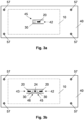
- Fig. 3a and 3b show schematically a part of a system according to an embodiment, in a top view.
- the plate 40 (cf. Fig. 2 ) is visible; the energy storage device 10, arranged below said plate 40 is not visible and, thus, drawn with broken lines.
- the plate 40 is shown with a U-cutout 45, thus building the elastic plate 42.
- the size change measuring unit 20 e.g. a strain gauge - is arranged. Additionally or as an alternative, another size change measuring unit may be arranged below the elastic plate 42 (not visible).
- the temperature measuring unit 30 is arranged, which is in mechanical contact with both the surface 12 and the elastic plate 42 (see Fig. 2 ). Since the temperature measuring unit 30 is not visible in a top view, it is also drawn with broken lines. Furthermore, screw heads 57 of the distance rod 55 (not visible) are depicted.
- Fig. 3b is quite similar to Fig. 3a ; the same or similar elements are given the same reference signs.
- Fig. 3b shows the plate 40 with a further cutout 46, i.e. an H-cutout, thus building elastic plates 42 and 43.
- the H-cutout has the size change measuring unit 20 arranged on an upper side and/or on a lower side of the elastic plates 42 or 43 (similar to the arrangement with a U-cutout).
- This embodiment may have two temperature measuring units 30, or only one temperature measuring unit and a "dummy unit", which only functions for maintaining a tight contact between the surface 12 and the elastic plate 42 or 43, respectively.
- a capacitive plate (not shown) may be arranged over or under the plate 40.
- a capacitive plate arranged over the plate 40 measures a movement of the elastic plate 42.
- a capacitive plate arranged under the plate 40 may substitute the elastic plate 42 by an elastic capacitive plate that is in mechanical contact with the surface 12, via the temperature measuring unit 30. In this embodiment, the plate 40 does not need any cutouts.
- a ferromagnetic rod may be arranged on the cutout 45 and/or 46, or directly on the temperature measuring unit 30., e.g. on an area close to its tip (or their tips), wherein the ferromagnetic rod is moveable within a coil.
- a combined sub-system may comprise the temperature measuring unit 30 arranged on a surface 12, 14, 16 of the energy storage device 10; an elastic plate 42, designed as a U-cutout or an H-cutout of a surrounding plate 40; and the size change measuring unit 20 arranged on the elastic plate 42, wherein the temperature measuring unit 30 is in mechanical contact with both the surface and the elastic plate 42, so that each size change of the surface of the energy storage device 10 leads to a size change of the elastic plate 42.
- Such a combined sub-system may be provided as a module, which could be arranged in a simple way - e.g. by gluing it below a rectangle cutout of plate 40 - between the surface 12, 14, 16 of the energy storage device 10 and said plate 40.
- Fig. 4 shows schematically a further part of a system according to an embodiment.
- Fig. 4 shows an arrangement with a plurality of energy storage devices 10.
- a ribbon-formed size change measuring unit 20 e.g. a strain gauge, is arranged tightly.
- Fig. 5 shows a flow diagram 100 according to an embodiment.
- a size change of at least one surface of the energy storage device 10 (see, e.g., Fig. 2 ) is measured.
- a temperature of the energy storage device 10 is measured.
- a present quality of an energy storage device 10 is estimated, based on the size change and/or the temperature of the energy storage device 10.
- Further steps, based on the estimating of the present quality of the energy storage device 10, may comprise: outputting the estimating the present quality of the energy storage device 10; turning off a system that comprises the energy storage device 10; and/or turning on a cooling device and/or a moisture reduction means.
Landscapes
- Engineering & Computer Science (AREA)
- Power Engineering (AREA)
- Physics & Mathematics (AREA)
- General Physics & Mathematics (AREA)
- Microelectronics & Electronic Packaging (AREA)
- Manufacturing & Machinery (AREA)
- Chemical & Material Sciences (AREA)
- Chemical Kinetics & Catalysis (AREA)
- Electrochemistry (AREA)
- General Chemical & Material Sciences (AREA)
- Charge And Discharge Circuits For Batteries Or The Like (AREA)
Abstract
The invention relates to the field of energy storage devices, particularly for capacitors or accumulators. A method for estimating a present quality of the energy storage device (10) comprises the steps of:
measuring a first size change of a first surface of the energy storage device (10);
measuring a temperature and/or a second size change of a second surface of the energy storage device (10); and
estimating the present quality of the energy storage device (10), based on the first size change combined with the temperature and/or the second size change of the energy storage device (10).
measuring a first size change of a first surface of the energy storage device (10);
measuring a temperature and/or a second size change of a second surface of the energy storage device (10); and
estimating the present quality of the energy storage device (10), based on the first size change combined with the temperature and/or the second size change of the energy storage device (10).
Description
- The invention relates to the field of energy storage devices, particularly for capacitors, batteries or accumulators. The invention further relates to a system, to a use and to a non-transitory computer-readable storage medium.
- Energy storage devices, for instance capacitors or accumulators, may suffer from size changes, which may be caused, e.g., by moisture absorption by the energy storage device. The moisture absorption may lead to hygroscopic swelling, as an exemplary source of size change. This and/or the water uptake may lead to a worsened quality and/or, in at least some cases, to a damage of the energy storage device.
- It is an objective of the invention to provide a method for estimating a present quality of an energy storage device. This objective is achieved by the subject-matter of the independent claims. Further embodiments are evident from the dependent claims and the following description.
- One aspect relates to a method for estimating a present quality of an energy storage device, the method comprising the steps of:
- measuring a first size change of a first surface of the energy storage device;
- measuring a temperature and/or a second size change of a second surface of the energy storage device; and
- estimating the present quality of the energy storage device, based on the first size change combined with the temperature and/or the second size change of the energy storage device.
- The energy storage device may be a capacitor or an accumulator. The present quality of the energy storage device - sometimes also called its "decay status", "health status", or "degradation status" - may reflect its present ability to fulfil its function correctly and/or a risk of getting damaged. If, for example, a capacitor, whose metallic components are covered, coated, or laminated with a film comprising polymer, is exposed to humidity or moisture, water may be incorporated into the polymer. This, on the one hand, may worsen the present quality of this capacitor, e.g. by reducing its electric insulation resistance and/or by changing its dielectric properties. On the other hand, the water in the polymer film may, under voltage, be split (and/or due to another kind of reaction) to hydrogen. This, in at least some cases, led to an explosion, endangering the capacitor's surrounding. Hence, it is desirable to recognize the capacitor's quality decay early. This may also apply to other types of capacitors and/or accumulators.
- An incorporating of water into the polymer, in many cases, leads to a swelling of the capacitor. For instance, a capacitor with a height of 50 mm may increase its size by, e.g., 5 µm to 2 mm, both on its upper and on its lower surface. However, a change of size, e.g. a swelling, of the capacitor may also be caused, e.g., by a higher temperature of the energy storage device, e.g. caused by the capacitor's environment and/or its load. Hence, an avoiding of a "false alarm" - by excluding a "not-dangerous" swelling or increase of size - has been recognized as being desirable as well. Thus, a hygroscopic, that is moisture-induced, swelling of one or several materials within the energy storage device may lead to a geometric change that may be detected. But, this is not unambiguous, because similar geometric changes may occur merely due to temperature distribution changes in the energy storage device.
- The method measures a first size change of a first surface of the energy storage device and, optionally, a second size change of a second surface of the energy storage device. The first and the second surface are disjoint surfaces. The measurement of the first or second size change, respectively, may be conducted on the upper, the lower surface, and/or on at least one of the lateral surfaces of the energy storage device (the surfaces being disjoint). In at least some cases, measuring the upper surface may be preferred to the lower surface, e.g. due to spacing constraints. Depending on the type of the energy storage device and/or on the reason for its size change, the size change may be positive or negative, leading to an essentially convex or a concave, respectively, form of the surface. For the measurement, every device that is configured for detecting a size change or surface strain change may be used. Examples may comprise devices that measure a capacitive change, an inductive change and/or a resistive change. The capacitive change may be measured by measuring a distance between two opposing plates. The inductive change may be measured by measuring a shift of a metal in a coil. The resistive change may be measured by measuring the resistance change of a change in conductor cross section in a stretching or elongation, e.g. by a strain gauge.
- The method measures a temperature of the energy storage device. The temperature of the energy storage device may be compared to and/or related to an ambient temperature of the device. The measurement of the temperature may be conducted on the upper, the lower surface, and/or on at least one of the lateral surfaces of the energy storage device. The temperature measurement may be conducted by any temperature sensor. For example, sensors that are in contact with the energy storage device may be used, e.g. a PTC (Positive Temperature Coefficient Thermistor), an NTC (Negative Temperature Coefficient Thermistor), or a thermocouple element, and/or devices that do not touch the energy storage device, e.g. a pyrometer.
- The present quality of the energy storage device can, then, be estimated, based on the size change and/or the temperature of the energy storage device. For instance, if a size change (e.g. a swelling) can be related to a proportional temperature change, the present quality of the energy storage device or its damage risk may be evaluated differently than in cases when the temperature has stayed almost constant. As a consequence, this method provides not only a method for estimating a present quality of the energy storage device, but also reduces a risk of a "false alarm".
- The present quality of the energy storage device may be evaluated, e.g., according to a category, e.g. a mark between 1 and 9, or a colour-category like "red/yellow/green". An example of the colour-category could be something like: "green, because expansion is only caused by higher temperature; yellow, because only slight increase; forecast for worsening time possible; red: crucial, maintenance required, danger".
- In various embodiments, the method further comprises at least one step of: Outputting the estimating the present quality of the energy storage device, e.g. outputting to a display and/or to a database, sending a message, outputting an alarm; turning off a system that comprises the energy storage device; and/or turning on a cooling device and/or a moisture reduction means. Outputting the estimating the present quality of the energy storage device may be a basis for service measures, e.g. substituting at least the energy storage device, and/or a board (PCB) that holds the device, and/or further service measures. Furthermore, a predictive maintenance may be planned and/or done by the present quality and/or by a time-series or history of present quality estiamtions.
- In various embodiments, the present quality of the energy storage device is estimated based on a ratio between the first and/or the second size change of at least one surface in a predefined timespan and a change of the temperature in said predefined timespan. By considering both the size change and the temperature of the energy storage device, the estimation quality may be significantly increased.
- In various embodiments, the present quality of the energy storage device is estimated based on a ratio between the first size change of a lateral surface and the second size change of an upper or lower surface. In at least some cases, measuring the size change of the upper surface may be preferred to the lower surface, e.g. due to spacing constraints. Accordingly, an expansion of one surface, but contraction of another surface can be used to identify a moisture-driven size change at a given temperature - and/or to exclude other reasons -, particularly when thermal expansion can be expected at a given value.
- In some embodiments, the present quality of the energy storage device is estimated based only on the temperature and/or a temperature gradient that is measured, to provide an indication of an alarm. This may be used to prevent serious failures and or to provide an early indication for then, e.g. for an overheating of the energy storage device.
- In various embodiments, the present quality of the energy storage device is determined based on a plurality of historic data and/or of a simulation of the first and/or second size changes and/or temperatures. The historic data may be stored in a database, possibly specific for each kind of energy storage device. The database may be placed on a central server and/or close to the energy storage device, e.g. in a control unit that runs the method described above and/or below. Based on this, measured and metrics - e.g. a "normal" ratio of size changes and/or temperatures - may be computed, related to each other, and compared to values from stored model values and/or real-world values stored in the database. Thereby, an expansion of one surface, but contraction of another surface can be used to identify a moisture-driven size change at a given temperature, when thermal expansion can be expected at a given value.
- In various embodiments, the energy storage device is a capacitor, particularly a film capacitor. The film may comprisepolypropylene (PP), polyethylene terephthalate (PET), polyethylene naphthalate (PEN), polyphenylene sulfide (PPS), polycarbonate (PC), functionally enhanced subvariants including nanostructured materials, another polymer, and/or a combination of these materials. For example, a polymer film type capacitor may serve as a filter capacitor, with a capacity between 1 µF and 5000 µF, particularly between 10 µF and 100 µF, and specified for a voltage between 100 V and 3000 V, e.g. for 350 V AC. Such a capacitor may have an edge length between 10 mm and 500 mm, particularly between 20 mm and 60 mm. The size change of such a capacitor may be below 2 mm, particularly below 1 mm, for each surface. The capacitor types may include electrolyte condensators.
- In various embodiments, the energy storage device is an accumulator or a battery, particularly a battery cell. The accumulator or battery may, e.g., be specified for a voltage between 0.5 and 10V, and for a capacity between 1 Ah and 1000 Ah. The accumulator may have an edge length between 10 mm and 500 mm, particularly between 20 mm and 60 mm. The size change of such an accumulator may be below 2 mm, particularly below 1 mm, for each surface.
- In various embodiments, the first and/or second size change is measured by a size change measuring unit, particularly by a device that measures a capacitive change, an inductive change and/or a resistive change. The capacitive change may be measured by measuring a distance of two opposite plates. The inductive change may be measured by measuring a shift of a metal in a coil. The resistive change may be measured by measuring a stretching or elongation, e.g. by a strain gauge.
- In various embodiments, the temperature is measured by a temperature measuring unit, particularly by a sensor that is in contact with the energy storage device, and/or by a contactless sensor, which does not touch the energy storage device. An example for the sensor that is in contact may be, e.g., a PTC (Positive Temperature Coefficient Thermistor), an NTC (Negative Temperature Coefficient Thermistor), or a thermocouple element. An example for the contactless sensor is, e.g., an infrared sensor or a pyrometer. Further temperature measuring unit(s) may be used, e.g. for measuring an ambient temperature. Such a temperature measuring unit may be arranged at a sufficiently remote location, for example on the backside of a PCB. Furthermore, a system may be provided that is configured, e.g., to evaluate the difference between the said capacitor's temperature and said ambient temperature.
- In some embodiments, measuring the first and/or second size change is performed by a ribbon-formed strain gauge arranged tightly around the energy storage device. Such a ribbon may advantageously be easy to apply and thus, reduce the manufacturing costs for conducting a method as described above and/or below.
- In various embodiments, the measuring the first and/or second size change and measuring the temperature of the energy storage device is performed by a combined sub-system. The combined sub-system comprises the temperature measuring unit arranged on a surface of the energy storage device; an elastic plate, designed as a U-cutout or an H-cutout of a surrounding plate, and the size change measuring unit arranged on the elastic plate. And, the temperature measuring unit is in mechanical contact with both the surface and the elastic plate, so that each size change of the surface of the energy storage device leads to a size change of the elastic plate.
- The "combined size-temperature-change sub-system" may build a module. The size change measuring unit may be arranged on one side of the elastic plate or on both sides. In case of using two change measuring units, they may be arranged as part of a Wheatstone bridge, thus increasing its sensitivity. The size change measuring unit may be arranged, e.g. by gluing (for example using a heat-coupling glue, e.g. a zero-shrink adhesive), by welding, soldering, sintering, using thin-film technology and/or by other fixation means.
- In an embodiment, the elastic plate that is designed as a U-cutout has the size change measuring unit arranged on an upper side and/or on a lower side of the elastic plate.
- In an embodiment, the elastic plate that is designed as an H-cutout has the size change measuring unit arranged on an upper side and/or on a lower side of the elastic plate and/or between the tips of the elastic plate. This may advantageously further increase the sensitivity of the change measuring unit.
- In some embodiments, the first and/or second size change is measured for a plurality of energy storage devices. In these embodiments, only one temperature measuring unit may be provided, and/or several temperature measuring units may be provided, and only one of them (e.g. the one with the highest temperature) is used for estimating the present quality of the energy storage device. This solution may save cost, because fewer elements are needed. And, in case of a significant degradation of at least one of the energy storage devices, in at least some cases the complete "block" is removed for service, repair and/or substitution. In cases a strain gauge is used that wraps around or covers multiple surfaces of one capacitor or a plurality of capacitors, in particular in immediate contact and/or attachment means mediated contact of as much surface as possible, the measurement sensitivity may be increased by this.
- An aspect relates to a combined sub-system as described above and/or below, i.e. a "combined size-temperature-change sub-system", for measuring a first and/or a second size change and a temperature of the energy storage device. This subsystem may be designed as a module, e.g. for enhancing its applicability.
- An aspect relates to a system for estimating a decay status of an energy storage device, the system comprising: the energy storage device; a size change measuring unit; a temperature measuring unit; and a control unit, configured for conducting any one of the methods described above and/or below.
- An aspect relates to a use of a system as described above and/or below for estimating a decay status of an energy storage device for predicting the remaining useful life of the capacitors and/or for estimating a moisture absorption by a capacitor.
- An aspect relates to a non-transitory computer-readable storage medium having a program stored therein, which, when executed on a processor of a control unit instructs the control unit to perform a method as described above and/or below.
- It should be noted that two or more embodiments described above and/or below can be combined, as far as technically feasible.
- For further clarification, the invention is described by means of embodiments shown in the figures. These embodiments are to be considered as examples only, but not as limiting.
- The drawings depict:
- Fig. 1a, 1b, 1c
- schematically size changes of a surface of an energy storage device;
- Fig. 2
- schematically a system according to an embodiment;
- Fig. 3a, 3b
- schematically a part of a system according to an embodiment;
- Fig. 4
- schematically a further part of a system according to an embodiment;
- Fig. 5
- a flow diagram according to an embodiment.
-
Fig. 1a, 1b, and 1c show schematically a profile of a surface of three different energy storage devices after the devices underwent a size change. The brighter the area shown is, the more elevation the surface shows, compared to its lowest points. The pictures shown depict an upper surface - an area of about 30 mm x 50 mm - of several types of capacitors. The differences of the arrangement within the capacitor lead to several different patterns.Fig. 1a shows about 300 µm elevation difference with a less deep centre line.Fig. 1b shows about 150 µm elevation difference with a pronounced centre line.Fig. 1c shows about 300 µm elevation without a centre line. -
Fig. 2 shows schematically a system according to an embodiment, in a side view. Anenergy storage device 10, e.g. a capacitor, is arranged on a PCB (Printed Circuit Board) 50, e.g. by soldering. Theenergy storage device 10 has atop surface 12, abottom surface 14 and (e.g. four) lateral surfaces 16. The system further comprises aplate 40 that is mounted on top of theenergy storage device 10. On thetop surface 12, atemperature measuring unit 30 is arranged, e.g. by means of athermal interface material 35. Thethermal interface material 35 may be a glue (for example using a heat-coupling glue), or thetemperature measuring unit 30 is arranged by welding, etc. Thetemperature measuring unit 30 is in mechanical contact with both thesurface 12 and anelastic plate 42, which is a part of the (surrounding)plate 40. Theelastic plate 42 may be designed as a U-cutout or an H-cutout of the surroundingplate 40; see e.g.Fig. 3a or Fig. 3b , respectively. Due to this arrangement, that each size change, e.g. a raising or lowering, of thesurface 12 of theenergy storage device 10 leads to a raising or lowering of theelastic plate 42. This bending of theelastic plate 42 can be measured by at least one size change measuring unit. Theplate 40 has a distinct distance to thetop surface 12, to keep a tight contact between thesurface 12 and theelastic plate 42, via thetemperature measuring unit 30 and thethermal interface material 35. The distinct distance between thetop surface 12 and theplate 40 may be realised by adistance rod 55, e.g. mounted by screws (screwhead 57 visible inFig. 2 ) on thePCB 50 and penetrating through theplate 40. -
Fig. 3a and 3b show schematically a part of a system according to an embodiment, in a top view. In this top view, the plate 40 (cf.Fig. 2 ) is visible; theenergy storage device 10, arranged below saidplate 40 is not visible and, thus, drawn with broken lines. InFig. 3a , theplate 40 is shown with a U-cutout 45, thus building theelastic plate 42. On top of theelastic plate 42, the size change measuring unit 20 - e.g. a strain gauge - is arranged. Additionally or as an alternative, another size change measuring unit may be arranged below the elastic plate 42 (not visible). Also below theelastic plate 42, thetemperature measuring unit 30 is arranged, which is in mechanical contact with both thesurface 12 and the elastic plate 42 (seeFig. 2 ). Since thetemperature measuring unit 30 is not visible in a top view, it is also drawn with broken lines. Furthermore, screw heads 57 of the distance rod 55 (not visible) are depicted. -
Fig. 3b is quite similar toFig. 3a ; the same or similar elements are given the same reference signs.Fig. 3b shows theplate 40 with afurther cutout 46, i.e. an H-cutout, thus buildingelastic plates change measuring unit 20 arranged on an upper side and/or on a lower side of theelastic plates 42 or 43 (similar to the arrangement with a U-cutout). Additionally or as an alternative, there may be a sizechange measuring unit 24 arranged between the tips of theelastic plates temperature measuring units 30, or only one temperature measuring unit and a "dummy unit", which only functions for maintaining a tight contact between thesurface 12 and theelastic plate - For embodiments, which use as the change measuring unit 20 a device that measures a capacitive change, a capacitive plate (not shown) may be arranged over or under the
plate 40. A capacitive plate arranged over theplate 40, measures a movement of theelastic plate 42. A capacitive plate arranged under theplate 40, may substitute theelastic plate 42 by an elastic capacitive plate that is in mechanical contact with thesurface 12, via thetemperature measuring unit 30. In this embodiment, theplate 40 does not need any cutouts. - For embodiments, which use as the change measuring unit 20 a device that measures an inductive change, a ferromagnetic rod may be arranged on the
cutout 45 and/or 46, or directly on the temperature measuring unit 30., e.g. on an area close to its tip (or their tips), wherein the ferromagnetic rod is moveable within a coil. - Some of the components shown in
Figs. 2 ,3a, 3b may be provided as a combined sub-system, which may comprise thetemperature measuring unit 30 arranged on asurface energy storage device 10; anelastic plate 42, designed as a U-cutout or an H-cutout of a surroundingplate 40; and the sizechange measuring unit 20 arranged on theelastic plate 42, wherein thetemperature measuring unit 30 is in mechanical contact with both the surface and theelastic plate 42, so that each size change of the surface of theenergy storage device 10 leads to a size change of theelastic plate 42. Such a combined sub-system may be provided as a module, which could be arranged in a simple way - e.g. by gluing it below a rectangle cutout of plate 40 - between thesurface energy storage device 10 and saidplate 40. -
Fig. 4 shows schematically a further part of a system according to an embodiment.Fig. 4 shows an arrangement with a plurality ofenergy storage devices 10. Around the plurality ofenergy storage devices 10, a ribbon-formed sizechange measuring unit 20, e.g. a strain gauge, is arranged tightly. -
Fig. 5 shows a flow diagram 100 according to an embodiment. In astep 102, a size change of at least one surface of the energy storage device 10 (see, e.g.,Fig. 2 ) is measured. In astep 104, a temperature of theenergy storage device 10 is measured. In astep 102, a present quality of anenergy storage device 10 is estimated, based on the size change and/or the temperature of theenergy storage device 10. - Further steps, based on the estimating of the present quality of the
energy storage device 10, may comprise: outputting the estimating the present quality of theenergy storage device 10; turning off a system that comprises theenergy storage device 10; and/or turning on a cooling device and/or a moisture reduction means. -
- 10
- energy storage device
- 12, 14, 16
- top / bottom / lateral surface
- 20
- size change measuring unit
- 30
- temperature measuring unit
- 35
- thermal interface material
- 40
- surrounding plate
- 42
- elastic plate
- 43
- further elastic plate
- 45
- cutout
- 46
- further cutout
- 50
- PCB (Printed Circuit Board)
- 55
- distance rod
- 57
- screw head
Claims (15)
- A method for estimating a present quality of an energy storage device (10), the method comprising the steps of:measuring a first size change of a first surface of the energy storage device (10);measuring a temperature and/or a second size change of a second surface of the energy storage device (10); andestimating the present quality of the energy storage device (10), based on the first size change combined with the temperature and/or the second size change of the energy storage device (10).
- The method of claim 1,
further comprising at least one step of:outputting the estimating of the present quality of the energy storage device (10);turning off a system that comprises the energy storage device (10); and/orturning on a cooling device and/or a moisture reduction means. - The method of any one of the preceding claims,
wherein the present quality of the energy storage device (10) is estimated based on a ratio between the first and/or the second size change of at least one surface in a predefined timespan and a change of the temperature in said predefined timespan. - The method of any one of the preceding claims,
wherein the present quality of the energy storage device (10) is estimated based on a ratio between the first size change of a lateral surface and the second size change of a upper or lower surface. - The method of any one of the preceding claims,
wherein the present quality of the energy storage device (10) is determined based on a plurality of historic data and/or of a simulation of the first and/or second size changes and/or temperatures. - The method of any one of the preceding claims,
wherein the energy storage device (10) is a capacitor, particularly a film capacitor, the film comprising polypropylene (PP), polyethylene terephthalate (PET), polyethylene naphthalate (PEN), polyphenylene sulfide (PPS), polycarbonate (PC), functionally enhanced subvariants including nanostructured materials, another polymer, and/or a combination of these materials, and/or the energy storage device (10) is an accumulator or a battery, particularly a battery cell. - The method of any one of the preceding claims,wherein the first and/or second size change is measured by a size change measuring unit (20), particularly by a device that measures a capacitive change, an inductive change and/or a resistive change, and/orwherein the temperature is measured by a temperature measuring unit (30), particularly by a sensor that is in contact with the energy storage device, and/or by a contactless sensor.
- The method of any one of the preceding claims,
wherein measuring the first and/or second size change is performed by a ribbon-formed strain gauge arranged tightly around the energy storage device (10). - The method of any one of the preceding claims,wherein measuring the first and/or second size change and measuring the temperature of the energy storage device (10) is performed by a combined sub-system,wherein the combined sub-system comprises:the temperature measuring unit (30) arranged on a surface (12, 14, 16) of the energy storage device (10);an elastic plate (42), designed as a U-cutout or an H-cutout of a surrounding plate (40); andthe size change measuring unit (20) arranged on the elastic plate (42),wherein the temperature measuring unit (30) is in mechanical contact with both the surface and the elastic plate (42), so that each of the first and/or second size change of the surface of the energy storage device (10) leads to a size change of the elastic plate (42).
- The method of claim 9,wherein the elastic plate (42) that is designed as a U-cutout has the size change measuring unit (20) arranged on an upper side and/or on a lower side of the elastic plate (42), and/orwherein the elastic plate (42) that is designed as an H-cutout has the size change measuring unit (20) arranged on an upper side and/or on a lower side of the elastic plates (42, 43) and/or between the tips of the elastic plates (42, 43).
- The method of any one of the preceding claims,
wherein the first and/or second size change is measured for a plurality of energy storage devices (10). - A combined sub-system according to claim 9 or 10 for measuring a first and/or a second size change and a temperature of the energy storage device (10).
- A system for estimating a present quality of an energy storage device (10), the system comprising:the energy storage device (10);a size change measuring unit (20);a temperature measuring unit (30); anda control unit, configured for conducting any one of the claims 1-11.
- Use of a system according to claim 13 for estimating a present quality of an energy storage device (10) for predicting the remaining useful life of the capacitors and/or for estimating a moisture absorption by a capacitor.
- A non-transitory computer-readable storage medium having a program stored therein, which, when executed on a processor of a control unit instructs the control unit to perform a method according to any one of claims 1-11.
Priority Applications (3)
| Application Number | Priority Date | Filing Date | Title |
|---|---|---|---|
| EP23173633.1A EP4465315A1 (en) | 2023-05-16 | 2023-05-16 | Method to detect a size change in an energy storage device |
| CN202410597494.XA CN118999334A (en) | 2023-05-16 | 2024-05-14 | Method of detecting dimensional changes in energy storage devices |
| US18/663,248 US20240384976A1 (en) | 2023-05-16 | 2024-05-14 | Method to Detect a Size Change in an Energy Storage Device |
Applications Claiming Priority (1)
| Application Number | Priority Date | Filing Date | Title |
|---|---|---|---|
| EP23173633.1A EP4465315A1 (en) | 2023-05-16 | 2023-05-16 | Method to detect a size change in an energy storage device |
Publications (1)
| Publication Number | Publication Date |
|---|---|
| EP4465315A1 true EP4465315A1 (en) | 2024-11-20 |
Family
ID=86387008
Family Applications (1)
| Application Number | Title | Priority Date | Filing Date |
|---|---|---|---|
| EP23173633.1A Pending EP4465315A1 (en) | 2023-05-16 | 2023-05-16 | Method to detect a size change in an energy storage device |
Country Status (3)
| Country | Link |
|---|---|
| US (1) | US20240384976A1 (en) |
| EP (1) | EP4465315A1 (en) |
| CN (1) | CN118999334A (en) |
Citations (5)
| Publication number | Priority date | Publication date | Assignee | Title |
|---|---|---|---|---|
| GB2263775A (en) * | 1992-01-23 | 1993-08-04 | James Edward Oakley | Strain measuring device |
| EP2620965A1 (en) * | 2012-01-25 | 2013-07-31 | Volvo Car Corporation | Supercapacitors assembly with extended lifetime by heat and charging/discharging protection management of said supercapacitors |
| US20160116548A1 (en) * | 2014-10-24 | 2016-04-28 | Qnovo Inc. | Circuitry and techniques for determining swelling of a battery/cell and adaptive charging circuitry and techniques based thereon |
| US10637108B1 (en) * | 2016-12-09 | 2020-04-28 | Cornell Dubilier Marketing, Inc. | Apparatus for detecting expansion of an energy storage device case |
| US20220181713A1 (en) * | 2020-12-09 | 2022-06-09 | VLTRU Systems, LLC | Battery module and battery rack with enhanced fire safety features, and applications thereof |
-
2023
- 2023-05-16 EP EP23173633.1A patent/EP4465315A1/en active Pending
-
2024
- 2024-05-14 US US18/663,248 patent/US20240384976A1/en active Pending
- 2024-05-14 CN CN202410597494.XA patent/CN118999334A/en active Pending
Patent Citations (5)
| Publication number | Priority date | Publication date | Assignee | Title |
|---|---|---|---|---|
| GB2263775A (en) * | 1992-01-23 | 1993-08-04 | James Edward Oakley | Strain measuring device |
| EP2620965A1 (en) * | 2012-01-25 | 2013-07-31 | Volvo Car Corporation | Supercapacitors assembly with extended lifetime by heat and charging/discharging protection management of said supercapacitors |
| US20160116548A1 (en) * | 2014-10-24 | 2016-04-28 | Qnovo Inc. | Circuitry and techniques for determining swelling of a battery/cell and adaptive charging circuitry and techniques based thereon |
| US10637108B1 (en) * | 2016-12-09 | 2020-04-28 | Cornell Dubilier Marketing, Inc. | Apparatus for detecting expansion of an energy storage device case |
| US20220181713A1 (en) * | 2020-12-09 | 2022-06-09 | VLTRU Systems, LLC | Battery module and battery rack with enhanced fire safety features, and applications thereof |
Also Published As
| Publication number | Publication date |
|---|---|
| US20240384976A1 (en) | 2024-11-21 |
| CN118999334A (en) | 2024-11-22 |
Similar Documents
| Publication | Publication Date | Title |
|---|---|---|
| KR100538070B1 (en) | Method of forecast for remainding life, structure of temperature detection and electronic equipment having the same | |
| US6959599B2 (en) | Level detector for storage tanks for fluids | |
| TW201937803A (en) | Battery pack and method for obtaining temperature measurements within a battery pack | |
| KR20120021393A (en) | Protection circuit module including thermistor and battery pack with same | |
| JP2012505513A (en) | Cell module assembly insulation inspection apparatus and method, and probe for the same | |
| GB2582299A (en) | A multilayered sensing apparatus and method of use | |
| LU92930B1 (en) | Internal battery heating unit with thin-printed foil | |
| EP2088440A1 (en) | Monitoring of capacitor | |
| US10884054B2 (en) | Detecting deterioration of an electrical circuit in an aggressive environment | |
| US10955372B2 (en) | Integrated environmental sensor for damage sensing | |
| EP4465315A1 (en) | Method to detect a size change in an energy storage device | |
| CN103630255B (en) | Capacitance temperature to operating uninterrupted power source carries out the system of on-line monitoring | |
| CN117741523B (en) | Hard plate monitoring method, system, terminal and medium based on magnetic induction sensor | |
| GB2594294A (en) | Apparatus | |
| US20230228824A1 (en) | Leakage characterization for electronic circuit temperature monitoring | |
| CN116998044B (en) | Battery pack and battery management system | |
| JP5882849B2 (en) | Electronic equipment installation environment judgment device | |
| US20230400361A1 (en) | Systems and methods for cell temperature measurement | |
| CN117651856A (en) | Measuring part stress with in-situ sensors | |
| US20210396606A1 (en) | Printed circuit board having a strain gauge | |
| WO2021111228A1 (en) | Leakage characterization and management for electronic circuit enhancement | |
| KR101002573B1 (en) | Slot Diagnosis Device | |
| US20260036501A1 (en) | Device and method for detecting rupture behavior of a battery cell | |
| CN219868378U (en) | Voltage stabilizer assembly, air conditioner control system and air conditioner | |
| US20250183402A1 (en) | Thermal management film for detecting and/or for regulating a temperature of an electrical device |
Legal Events
| Date | Code | Title | Description |
|---|---|---|---|
| PUAI | Public reference made under article 153(3) epc to a published international application that has entered the european phase |
Free format text: ORIGINAL CODE: 0009012 |
|
| STAA | Information on the status of an ep patent application or granted ep patent |
Free format text: STATUS: THE APPLICATION HAS BEEN PUBLISHED |
|
| AK | Designated contracting states |
Kind code of ref document: A1 Designated state(s): AL AT BE BG CH CY CZ DE DK EE ES FI FR GB GR HR HU IE IS IT LI LT LU LV MC ME MK MT NL NO PL PT RO RS SE SI SK SM TR |
|
| STAA | Information on the status of an ep patent application or granted ep patent |
Free format text: STATUS: REQUEST FOR EXAMINATION WAS MADE |
|
| 17P | Request for examination filed |
Effective date: 20250324 |