EP4465271A1 - Calibrating an infrared (ir) sensor in a fire sensing device - Google Patents
Calibrating an infrared (ir) sensor in a fire sensing device Download PDFInfo
- Publication number
- EP4465271A1 EP4465271A1 EP24172034.1A EP24172034A EP4465271A1 EP 4465271 A1 EP4465271 A1 EP 4465271A1 EP 24172034 A EP24172034 A EP 24172034A EP 4465271 A1 EP4465271 A1 EP 4465271A1
- Authority
- EP
- European Patent Office
- Prior art keywords
- sensor
- radiation level
- environment
- image
- camera
- Prior art date
- Legal status (The legal status is an assumption and is not a legal conclusion. Google has not performed a legal analysis and makes no representation as to the accuracy of the status listed.)
- Pending
Links
Images



Classifications
-
- G—PHYSICS
- G01—MEASURING; TESTING
- G01J—MEASUREMENT OF INTENSITY, VELOCITY, SPECTRAL CONTENT, POLARISATION, PHASE OR PULSE CHARACTERISTICS OF INFRARED, VISIBLE OR ULTRAVIOLET LIGHT; COLORIMETRY; RADIATION PYROMETRY
- G01J5/00—Radiation pyrometry, e.g. infrared or optical thermometry
- G01J5/0014—Radiation pyrometry, e.g. infrared or optical thermometry for sensing the radiation from gases, flames
- G01J5/0018—Flames, plasma or welding
-
- G—PHYSICS
- G08—SIGNALLING
- G08B—SIGNALLING SYSTEMS, e.g. PERSONAL CALLING SYSTEMS; ORDER TELEGRAPHS; ALARM SYSTEMS
- G08B17/00—Fire alarms; Alarms responsive to explosion
- G08B17/12—Actuation by presence of radiation or particles, e.g. of infrared radiation or of ions
- G08B17/125—Actuation by presence of radiation or particles, e.g. of infrared radiation or of ions by using a video camera to detect fire or smoke
-
- G—PHYSICS
- G01—MEASURING; TESTING
- G01J—MEASUREMENT OF INTENSITY, VELOCITY, SPECTRAL CONTENT, POLARISATION, PHASE OR PULSE CHARACTERISTICS OF INFRARED, VISIBLE OR ULTRAVIOLET LIGHT; COLORIMETRY; RADIATION PYROMETRY
- G01J5/00—Radiation pyrometry, e.g. infrared or optical thermometry
- G01J5/02—Constructional details
- G01J5/025—Interfacing a pyrometer to an external device or network; User interface
-
- G—PHYSICS
- G01—MEASURING; TESTING
- G01J—MEASUREMENT OF INTENSITY, VELOCITY, SPECTRAL CONTENT, POLARISATION, PHASE OR PULSE CHARACTERISTICS OF INFRARED, VISIBLE OR ULTRAVIOLET LIGHT; COLORIMETRY; RADIATION PYROMETRY
- G01J5/00—Radiation pyrometry, e.g. infrared or optical thermometry
- G01J5/02—Constructional details
- G01J5/027—Constructional details making use of sensor-related data, e.g. for identification of sensor parts or optical elements
-
- G—PHYSICS
- G01—MEASURING; TESTING
- G01J—MEASUREMENT OF INTENSITY, VELOCITY, SPECTRAL CONTENT, POLARISATION, PHASE OR PULSE CHARACTERISTICS OF INFRARED, VISIBLE OR ULTRAVIOLET LIGHT; COLORIMETRY; RADIATION PYROMETRY
- G01J5/00—Radiation pyrometry, e.g. infrared or optical thermometry
- G01J5/60—Radiation pyrometry, e.g. infrared or optical thermometry using determination of colour temperature
- G01J5/601—Radiation pyrometry, e.g. infrared or optical thermometry using determination of colour temperature using spectral scanning
-
- G—PHYSICS
- G01—MEASURING; TESTING
- G01J—MEASUREMENT OF INTENSITY, VELOCITY, SPECTRAL CONTENT, POLARISATION, PHASE OR PULSE CHARACTERISTICS OF INFRARED, VISIBLE OR ULTRAVIOLET LIGHT; COLORIMETRY; RADIATION PYROMETRY
- G01J5/00—Radiation pyrometry, e.g. infrared or optical thermometry
- G01J5/80—Calibration
-
- G—PHYSICS
- G06—COMPUTING OR CALCULATING; COUNTING
- G06T—IMAGE DATA PROCESSING OR GENERATION, IN GENERAL
- G06T7/00—Image analysis
- G06T7/97—Determining parameters from multiple pictures
-
- G—PHYSICS
- G08—SIGNALLING
- G08B—SIGNALLING SYSTEMS, e.g. PERSONAL CALLING SYSTEMS; ORDER TELEGRAPHS; ALARM SYSTEMS
- G08B29/00—Checking or monitoring of signalling or alarm systems; Prevention or correction of operating errors, e.g. preventing unauthorised operation
- G08B29/18—Prevention or correction of operating errors
- G08B29/20—Calibration, including self-calibrating arrangements
- G08B29/24—Self-calibration, e.g. compensating for environmental drift or ageing of components
-
- H—ELECTRICITY
- H04—ELECTRIC COMMUNICATION TECHNIQUE
- H04N—PICTORIAL COMMUNICATION, e.g. TELEVISION
- H04N23/00—Cameras or camera modules comprising electronic image sensors; Control thereof
- H04N23/10—Cameras or camera modules comprising electronic image sensors; Control thereof for generating image signals from different wavelengths
- H04N23/12—Cameras or camera modules comprising electronic image sensors; Control thereof for generating image signals from different wavelengths with one sensor only
-
- G—PHYSICS
- G01—MEASURING; TESTING
- G01J—MEASUREMENT OF INTENSITY, VELOCITY, SPECTRAL CONTENT, POLARISATION, PHASE OR PULSE CHARACTERISTICS OF INFRARED, VISIBLE OR ULTRAVIOLET LIGHT; COLORIMETRY; RADIATION PYROMETRY
- G01J5/00—Radiation pyrometry, e.g. infrared or optical thermometry
- G01J2005/0077—Imaging
-
- G—PHYSICS
- G06—COMPUTING OR CALCULATING; COUNTING
- G06T—IMAGE DATA PROCESSING OR GENERATION, IN GENERAL
- G06T2207/00—Indexing scheme for image analysis or image enhancement
- G06T2207/10—Image acquisition modality
- G06T2207/10048—Infrared image
Definitions
- the present disclosure relates generally to devices, methods, and systems for calibrating an infrared (IR) sensor in a fire sensing device.
- IR infrared
- a fire alarm system may include a fire control panel and a plurality of fire sensing devices (e.g., smoke detectors), located throughout the building (e.g., on different floors and/or in different rooms of the building) that can sense a fire occurring in the building (e.g., by detecting smoke) and provide a notification of the fire to the occupants of the building via alarms.
- a fire sensing devices e.g., smoke detectors
- Maintaining the fire alarm system can include recalibration of the sensors of fire sensing devices of the system. Over time the sensors of a fire sensing device can drift out of a calibration due to environmental conditions. For example, infrared (IR) sensors used for flame detection can drift due to exposure to radiation. An IR sensor out of calibration can prevent a fire sensing device from detecting a flame.
- IR infrared
- a fire sensing device may have to be dismounted and shipped offsite for calibration that involves specialized calibration equipment by trained personnel.
- One device includes a camera configured to capture an image of an environment, an IR sensor configured to detect a radiation level of the environment, and a controller configured to compare a radiation level of the image of the environment captured by the camera to the radiation level of the environment detected by the IR sensor and calibrate the IR sensor based on the comparison.
- a camera configured to capture an image of an environment
- an IR sensor configured to detect a radiation level of the environment
- a controller configured to compare a radiation level of the image of the environment captured by the camera to the radiation level of the environment detected by the IR sensor and calibrate the IR sensor based on the comparison.
- a fire sensing device in accordance with the present disclosure can test and calibrate its IR sensor itself, without the involvement of a maintenance engineer or operator.
- the fire sensing device can utilize a camera in the fire sensing device to determine when the fire sensing device is in extreme darkness, which means the IR sensor should record a value of zero. If the IR sensor records a value other than zero, this can indicate that the IR sensor needs to be recalibrated, and the value can be used to calibrate (e.g., recalibrate) the IR sensor.
- fire sensing devices in accordance with the present disclosure may test their IR sensor, recalibrate their IR sensor, and/or transmit an alert that the IR sensor is out of calibration, which can reduce the chance of the fire sensing device delaying or missing the detection of a fire.
- a can refer to one or more such things, while “a plurality of” something can refer to more than one such things.
- a number of components can refer to one or more components, while “a plurality of components” can refer to more than one component.
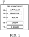
- FIG. 1 illustrates a block diagram of a fire sensing device 100 in accordance with an embodiment of the present disclosure.
- the fire sensing device 100 includes a controller (e.g., microcontroller) 102, a camera 108, and an IR sensor 110.
- Camera 108 can capture an image of an environment (e.g., the environment in which fire sensing device 100 is located), and IR sensor 110 can detect a radiation level of the environment.
- Controller 102 can include a processor 104 and a memory 106.
- Memory 106 can be any type of storage medium that can be accessed by processor 104 to perform various examples of the present disclosure.
- memory 106 can be a non-transitory computer readable medium having computer readable instructions (e.g., computer program instructions) stored thereon that are executable by processor 104 to calibrate the IR sensor 110 in the fire sensing device 100 in accordance with the present disclosure.
- processor 104 can execute the executable instructions stored in memory 106 to determine an environment (e.g., the environment in which the fire sensing device is located) has a radiation level equal to (e.g., at) or less than (e.g., below) a threshold radiation level based on an image captured by the camera 108 of the fire sensing device 100 (e.g., by comparing the radiation level of the image of the environment captured by the camera to the threshold radiation level), compare, responsive to determining the environment (e.g., the image of the environment) has a radiation level at or below the threshold radiation level, the radiation level to a radiation level of the environment detected by the IR sensor 110 of the fire sensing device 100, and calibrate the IR sensor 110 based on the comparison.
- an environment e.g., the environment in which the fire sensing device is located
- a radiation level equal to (e.g., at) or less than (e.g., below) a threshold radiation level based on an image captured by the camera 108 of the fire sens
- the camera 108 can be used for flame detection.
- the camera 108 can be a camera that captures the image of the environment using visible light.
- the camera 108 can capture the image of the environment in a red, green, and blue color space.
- the controller 102 can convert the image from the red, green, and blue color space to a number of hue saturation values and compare the number of hue saturation values to a number of hue saturation values detected by the IR sensor 110.
- the camera 108 can be a thermal imaging camera that captures a thermal image of the environment. Accordingly, the controller 102 can determine the radiation level of the thermal image of the environment.
- the threshold radiation level can be the radiation level when the fire sensing device 100 is in extreme darkness, which can be a hue saturation value of 0%. Accordingly, the IR sensor 110, if calibrated, can have a hue saturation value of 0%. If the IR sensor 110 records a hue saturation value other than 0%, this can indicate the IR sensor needs to be calibrated, and the recorded hue saturation value can be used to calibrate (e.g., recalibrate) the IR sensor 110.
- Calibrating the IR sensor 110 can comprise compensating for a difference (e.g., calibration error) between the radiation level of the image captured by the camera 108 and the radiation level of the environment detected by the IR sensor 110 by adding a correction factor (e.g., an offset) to the radiation level of the environment detected by the IR sensor 110 equal to a difference between a hue saturation value of the image and a hue saturation value of the radiation level of the environment detected by the IR sensor 110.
- a difference e.g., calibration error
- a correction factor e.g., an offset
- controller 102 can determine, responsive to the radiation level of the image of the environment captured by camera 108 being equal to or less than the threshold radiation level, an offset between the radiation level of the image and the radiation level of the environment detected by the IR sensor 110. Controller 102 can calibrate the IR sensor 110 based on the determined offset.
- the camera 108 can capture an additional image of the environment responsive to the radiation level of the image of the environment captured by the camera 108 being greater than the threshold radiation level.
- the controller 102 can determine whether a radiation level of the additional image of the environment captured by the camera 108 is equal to or less than the threshold radiation level, determine, responsive to the radiation level of the additional image of the environment captured by the camera 108 being equal to or less than the threshold radiation level, an additional offset between the radiation level of the additional image of the environment captured by the camera 108 and the radiation level of the environment detected by the IR sensor 110, and calibrate the IR sensor 110 based on the determined additional offset.
- the controller 102 can predict an end of life of the IR sensor 110 based on calibration frequency of IR sensor 110. For example, if the IR sensor 110 is being calibrated frequently or if the calibration error is increasing over time, the controller 102 can extrapolate when the IR sensor 110 will fall out of its operational specification.
- a threshold offset can be the amount of offset needed to the radiation level of the environment detected by the IR sensor 110 to prevent the IR sensor 110 from falling out of its operational specification before a particular amount of time (e.g., before night arrives) to do another recalibration.
- the controller 102 can generate an alert (e.g., message) that the IR sensor 110 is at end of life. In some examples, the controller 102 can transmit the alert.
- Figure 2 illustrates a method flow diagram 212 of a calibration of an IR sensor in a fire sensing device in accordance with an embodiment of the present disclosure.
- the method illustrated in Figure 2 can be performed by the fire sensing device previously described in connection with Figure 1 (e.g., the IR sensor can be IR sensor 110 previously described in connection with Figure 1 ).
- a controller e.g., controller 102 described in connection with Figure 1
- a camera e.g., camera 108 described in connection with Figure 1
- the controller can determine the environment includes an IR emitting body if the image includes any radiation or if the image includes a radiation level greater than a threshold radiation level. If the image includes an IR emitting body, no calibration is initiated, and the method concludes at block 218.
- the controller can determine the image of the environment includes a black body.
- the controller can determine the environment includes a black body if the image has no radiation or if the radiation level of the image is at or below the threshold radiation level. If the image includes a black body, the controller can determine the environment is ideal for calibration and calibration can begin at block 222.
- An IR sensor radiation level can be compared to the radiation level of the image captured by the IR camera at block 224. Detecting the radiation level of the image will be further described herein (e.g., in connection with Figure 3 ). A correction factor can be determined at block 226 based on the comparison.
- the correction factor can be used to calibrate the IR sensor at block 228. Calibrating the IR sensor can compensate for the difference between the radiation level of the image captured by the camera and the radiation level of the environment detected by the IR sensor by adding an offset as the correction factor to the radiation level of the environment detected by the IR sensor. For example, the correction factor can be added to the radiation level of the environment detected by the IR sensor equal to a difference between a hue saturation value of the image and a hue saturation value of the radiation level of the environment detected by the IR sensor.
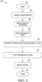
- Figure 3 illustrates a method flow diagram 340 of detecting an IR radiation level of an image captured by a camera in a fire sensing device in accordance with an embodiment of the present disclosure.
- the method illustrated in Figure 3 can be performed by the fire sensing device previously described in connection with Figure 1 (e.g., the camera can be camera 108 previously described in connection with Figure 1 ).
- a calibration (e.g., the calibration previously described in connection with Figure 2 ) can start.
- a camera e.g., camera 108 described in connection with Figure 1
- the camera can capture the image in a red, green, and blue color space.
- a processor e.g., processor 104 described in connection with Figure 1
- the processor can receive the image at block 346.
- the processor can preprocess the image at block 348.
- the pre-processing can include reading, denoising, and/or resizing the image.
- the processor can further convert the image from the red, green, and blue (RGB) color space to hue saturation values (HSV) to define a range of black color at block 350.
- RGB red, green, and blue
- HSV hue saturation values
- post processing of the image can be performed by the processor.
- the processor can determine whether the image includes an IR emitting body by comparing the hue saturation values of the image to hue saturation values of an image without an IR emitting body (e.g., without radiation) or hue saturation values of an image with radiation under a threshold radiation level.
- the processor can determine the image includes an IR emitting body if a number of hue saturation values of the image are greater than a threshold hue saturation value.
- the IR image can be displayed at 354 and the method can conclude at block 356.
- the IR image can then be used to calibrate the IR sensor, as described in connection with Figure 2 .
- Figure 4 illustrates a method flow diagram 460 of a calibration of an IR sensor in a fire sensing device in accordance with an embodiment of the present disclosure.
- the method illustrated in Figure 4 can be performed by the fire sensing device previously described in connection with Figure 1 (e.g., the IR sensor can be IR sensor 110 previously described in connection with Figure 1 ).
- a camera e.g., camera 108 described in connection with Figure 1
- a thermal camera can capture an image of an environment at block 462.
- the camera can execute image pre-processing including reading, denoising, and/or resizing at block 464.
- the camera can output an image and/or a thermal profile at block 466 after the image pre-processing.
- the image and/or thermal profile can be output to a controller (e.g., controller 102 described in connection with Figure 1 ) of the fire sensing device.
- the controller can execute feature extraction at block 468 to identify a heat signature (e.g., radiation level) of the image at block 470.
- the controller can determine whether the environment has a radiation level greater than a threshold radiation level based on the image captured by the camera by comparing the radiation level of the image to the threshold radiation level. If the environment in the image has a radiation level greater than the threshold radiation level, the controller can proceed to the next frame (e.g., the next image) captured by the camera at block 474.
- the controller can compare the radiation level of the image to a radiation level of the environment detected by an IR sensor (e.g., IR sensor 110 described in connection with Figure 1 ) of the fire sensing device at block 476. If the radiation level of the IR sensor is at or within a threshold range of the radiation level of the image, the controller can proceed to the next frame at block 474.
- an IR sensor e.g., IR sensor 110 described in connection with Figure 1
- the controller can perform a differential analysis by calculating the difference between the radiation level detected by the IR sensor and the radiation level of the image if the radiation level detected by the IR sensor is greater than or outside of the threshold range of the radiation level of the image.
- the controller can generate a correction factor based on the difference at block 480 and calibrate the IR sensor using the correction factor at block 482.
- a user notification can be transmitted at 484 in response to updating the calibration values of the IR sensor to inform the user that the IR sensor has been calibrated.
- FIG. 5 illustrates a block diagram of a fire alarm system 590 in accordance with an embodiment of the present disclosure.
- the system 590 can include a fire sensing device 500, a monitoring device 594, and a computing device 596.
- Fire sensing device 500 can be, for example, fire sensing device 100 previously described in connection with Figure 1 .
- the fire sensing device 500 can include a user interface 501.
- the user interface 501 can be a graphical user interface (GUI) that can provide and/or receive information to and/or from the user, the monitoring device 594, and/or the computing device 596.
- GUI graphical user interface
- the user interface 501 can display a message. The message can be displayed responsive to calibrating an IR sensor of fire sensing device 500, failing to calibrate the IR sensor, or predicting an end of life of the IR sensor.
- the monitoring device 594 can be a control panel, a fire detection control system, and/or a cloud computing device of a fire alarm system.
- the monitoring device 594 can be configured to send commands to and/or receive messages from a fire sensing device 500 via a wired or wireless network.
- the fire sensing device 500 can transmit (e.g., send) the monitoring device 594 a message responsive to calibrating the IR sensor, failing to calibrate the IR sensor, or predicting end of life of the IR sensor.
- the monitoring device 594 can receive messages from a number of fire sensing devices analogous to fire sensing device 500. For example, the monitoring device 594 can receive a message from each of a number of fire sensing devices analogous to fire sensing device 500 and create a maintenance schedule based on the messages from each of the number of fire sensing devices.
- the monitoring device 594 can include a user interface 595.
- the user interface 595 can be a GUI that can provide and/or receive information to and/or from a user and/or the fire sensing device 500.
- the user interface 595 can display messages and/or data received from the fire sensing device 500.
- the user interface 595 can display a message that the IR sensor requires maintenance, the IR sensor is calibrated, the IR sensor failed to calibrate, and/or the IR sensor is at end of life.
- computing device 596 can receive a message from fire sensing device 500 and/or monitoring device 594 via a wired or wireless network.
- the computing device 596 can be a personal laptop computer, a desktop computer, a mobile device such as a smart phone, a tablet, a wrist-worn device, and/or redundant combinations thereof, among other types of computing devices.
- a computing device 596 can include a user interface 597 to display messages from the monitoring device 594 and/or the fire sensing device 500.
- the user interface 597 can display a message that the IR sensor requires maintenance, the IR sensor is calibrated, the IR sensor failed to calibrate, and/or the IR sensor is at end of life.
- the networks described herein can be a network relationship through which fire sensing device 500, monitoring device 594, and/or computing device 596 can communicate with each other.
- Examples of such a network relationship can include a distributed computing environment (e.g., a cloud computing environment), a wide area network (WAN) such as the Internet, a local area network (LAN), a personal area network (PAN), a campus area network (CAN), or metropolitan area network (MAN), among other types of network relationships.
- the network can include a number of servers that receive information from, and transmit information to fire sensing device 500, monitoring device 594, and/or computing device 596 via a wired or wireless network.
- a "network” can provide a communication system that directly or indirectly links two or more computers and/or peripheral devices and allows a monitoring device 594 and/or a computing device 596 to access data and/or resources on a fire sensing device 500 and vice versa.
- a network can allow users to share resources on their own systems with other network users and to access information on centrally located systems or on systems that are located at remote locations.
- a network can tie a number of computing devices together to form a distributed control network (e.g., cloud).
- a network may provide connections to the Internet and/or to the networks of other entities (e.g., organizations, institutions, etc.). Users may interact with network-enabled software applications to make a network request, such as to get data. Applications may also communicate with network management software, which can interact with network hardware to transmit information between devices on the network.
- entities e.g., organizations, institutions, etc.
- network management software can interact with network hardware to transmit information between devices on the network.
Landscapes
- Physics & Mathematics (AREA)
- General Physics & Mathematics (AREA)
- Engineering & Computer Science (AREA)
- Spectroscopy & Molecular Physics (AREA)
- Multimedia (AREA)
- Emergency Management (AREA)
- Business, Economics & Management (AREA)
- Human Computer Interaction (AREA)
- Signal Processing (AREA)
- Computer Vision & Pattern Recognition (AREA)
- Theoretical Computer Science (AREA)
- Plasma & Fusion (AREA)
- Computer Security & Cryptography (AREA)
- Fire Alarms (AREA)
Abstract
Devices, methods, and systems for calibrating an infrared (IR) sensor in a fire sensing device are described herein. One device includes a camera configured to capture an image of an environment, an IR sensor configured to detect a radiation level of the environment, and a controller configured to compare a radiation level of the image of the environment captured by the camera to the radiation level of the environment detected by the IR sensor and calibrate the IR sensor based on the comparison.
Description
- The present disclosure relates generally to devices, methods, and systems for calibrating an infrared (IR) sensor in a fire sensing device.
- Large facilities, such as commercial buildings, office buildings, hospitals, and the like, as well as residential buildings, such as apartments, townhomes, single family homes, and the like may have a fire alarm system that can be triggered during an emergency situation (e.g., a fire) to warn occupants to evacuate. For example, a fire alarm system may include a fire control panel and a plurality of fire sensing devices (e.g., smoke detectors), located throughout the building (e.g., on different floors and/or in different rooms of the building) that can sense a fire occurring in the building (e.g., by detecting smoke) and provide a notification of the fire to the occupants of the building via alarms.
- Maintaining the fire alarm system can include recalibration of the sensors of fire sensing devices of the system. Over time the sensors of a fire sensing device can drift out of a calibration due to environmental conditions. For example, infrared (IR) sensors used for flame detection can drift due to exposure to radiation. An IR sensor out of calibration can prevent a fire sensing device from detecting a flame.
- Recalibration of sensors often requires tedious procedures and a significant amount of time. For example, a fire sensing device may have to be dismounted and shipped offsite for calibration that involves specialized calibration equipment by trained personnel.
-
-
Figure 1 illustrates a block diagram of a fire sensing device in accordance with an embodiment of the present disclosure. -
Figure 2 illustrates a method flow diagram of a calibration of an IR sensor in a fire sensing device in accordance with an embodiment of the present disclosure. -
Figure 3 illustrates a method flow diagram of detecting an IR radiation level of an image captured by a camera in a fire sensing device in accordance with an embodiment of the present disclosure. -
Figure 4 illustrates a method flow diagram of a calibration of an IR sensor in a fire sensing device in accordance with an embodiment of the present disclosure. -
Figure 5 illustrates a block diagram of a fire alarm system in accordance with an embodiment of the present disclosure. - Devices, methods, and systems for calibrating an infrared (IR) sensor in a fire sensing device are described herein. One device includes a camera configured to capture an image of an environment, an IR sensor configured to detect a radiation level of the environment, and a controller configured to compare a radiation level of the image of the environment captured by the camera to the radiation level of the environment detected by the IR sensor and calibrate the IR sensor based on the comparison.
- In contrast to previous fire sensing devices in which a person (e.g., maintenance engineer and/or operator) would have to manually test and calibrate an IR sensor in a fire sensing device, a fire sensing device in accordance with the present disclosure can test and calibrate its IR sensor itself, without the involvement of a maintenance engineer or operator. For example, the fire sensing device can utilize a camera in the fire sensing device to determine when the fire sensing device is in extreme darkness, which means the IR sensor should record a value of zero. If the IR sensor records a value other than zero, this can indicate that the IR sensor needs to be recalibrated, and the value can be used to calibrate (e.g., recalibrate) the IR sensor. Accordingly, fire sensing devices in accordance with the present disclosure may test their IR sensor, recalibrate their IR sensor, and/or transmit an alert that the IR sensor is out of calibration, which can reduce the chance of the fire sensing device delaying or missing the detection of a fire.
- In the following detailed description, reference is made to the accompanying drawings that form a part hereof. The drawings show by way of illustration how one or more embodiments of the disclosure may be practiced. These embodiments are described in sufficient detail to enable those of ordinary skill in the art to practice one or more embodiments of this disclosure. It is to be understood that other embodiments may be utilized and that mechanical, electrical, and/or process changes may be made without departing from the scope of the present disclosure.
- As will be appreciated, elements shown in the various embodiments herein can be added, exchanged, combined, and/or eliminated so as to provide a number of additional embodiments of the present disclosure. The proportion and the relative scale of the elements provided in the figures are intended to illustrate the embodiments of the present disclosure and should not be taken in a limiting sense.
- The figures herein follow a numbering convention in which the first digit or digits correspond to the drawing figure number and the remaining digits identify an element or component in the drawing. Similar elements or components between different figures may be identified by the use of similar digits. For example, 100 may reference element "00" in
Figure 1 , and a similar element may be referenced as 500 inFigure 5 . - As used herein, "a", "an", or "a number of" something can refer to one or more such things, while "a plurality of" something can refer to more than one such things. For example, "a number of components" can refer to one or more components, while "a plurality of components" can refer to more than one component.
-
Figure 1 illustrates a block diagram of afire sensing device 100 in accordance with an embodiment of the present disclosure. Thefire sensing device 100 includes a controller (e.g., microcontroller) 102, acamera 108, and anIR sensor 110. Camera 108 can capture an image of an environment (e.g., the environment in whichfire sensing device 100 is located), andIR sensor 110 can detect a radiation level of the environment. -
Controller 102 can include aprocessor 104 and amemory 106.Memory 106 can be any type of storage medium that can be accessed byprocessor 104 to perform various examples of the present disclosure. For example,memory 106 can be a non-transitory computer readable medium having computer readable instructions (e.g., computer program instructions) stored thereon that are executable byprocessor 104 to calibrate theIR sensor 110 in thefire sensing device 100 in accordance with the present disclosure. For instance,processor 104 can execute the executable instructions stored inmemory 106 to determine an environment (e.g., the environment in which the fire sensing device is located) has a radiation level equal to (e.g., at) or less than (e.g., below) a threshold radiation level based on an image captured by thecamera 108 of the fire sensing device 100 (e.g., by comparing the radiation level of the image of the environment captured by the camera to the threshold radiation level), compare, responsive to determining the environment (e.g., the image of the environment) has a radiation level at or below the threshold radiation level, the radiation level to a radiation level of the environment detected by theIR sensor 110 of thefire sensing device 100, and calibrate theIR sensor 110 based on the comparison. - In some examples, the
camera 108 can be used for flame detection. Thecamera 108 can be a camera that captures the image of the environment using visible light. For example, thecamera 108 can capture the image of the environment in a red, green, and blue color space. Thecontroller 102 can convert the image from the red, green, and blue color space to a number of hue saturation values and compare the number of hue saturation values to a number of hue saturation values detected by theIR sensor 110. - In a number of embodiments, the
camera 108 can be a thermal imaging camera that captures a thermal image of the environment. Accordingly, thecontroller 102 can determine the radiation level of the thermal image of the environment. - The threshold radiation level can be the radiation level when the
fire sensing device 100 is in extreme darkness, which can be a hue saturation value of 0%. Accordingly, theIR sensor 110, if calibrated, can have a hue saturation value of 0%. If theIR sensor 110 records a hue saturation value other than 0%, this can indicate the IR sensor needs to be calibrated, and the recorded hue saturation value can be used to calibrate (e.g., recalibrate) theIR sensor 110. Calibrating theIR sensor 110 can comprise compensating for a difference (e.g., calibration error) between the radiation level of the image captured by thecamera 108 and the radiation level of the environment detected by theIR sensor 110 by adding a correction factor (e.g., an offset) to the radiation level of the environment detected by theIR sensor 110 equal to a difference between a hue saturation value of the image and a hue saturation value of the radiation level of the environment detected by theIR sensor 110. - In some examples,
controller 102 can determine, responsive to the radiation level of the image of the environment captured bycamera 108 being equal to or less than the threshold radiation level, an offset between the radiation level of the image and the radiation level of the environment detected by theIR sensor 110.Controller 102 can calibrate theIR sensor 110 based on the determined offset. - The
camera 108 can capture an additional image of the environment responsive to the radiation level of the image of the environment captured by thecamera 108 being greater than the threshold radiation level. Thecontroller 102 can determine whether a radiation level of the additional image of the environment captured by thecamera 108 is equal to or less than the threshold radiation level, determine, responsive to the radiation level of the additional image of the environment captured by thecamera 108 being equal to or less than the threshold radiation level, an additional offset between the radiation level of the additional image of the environment captured by thecamera 108 and the radiation level of the environment detected by theIR sensor 110, and calibrate theIR sensor 110 based on the determined additional offset. - In a number of embodiments, the
controller 102 can predict an end of life of theIR sensor 110 based on calibration frequency ofIR sensor 110. For example, if theIR sensor 110 is being calibrated frequently or if the calibration error is increasing over time, thecontroller 102 can extrapolate when theIR sensor 110 will fall out of its operational specification. A threshold offset can be the amount of offset needed to the radiation level of the environment detected by theIR sensor 110 to prevent theIR sensor 110 from falling out of its operational specification before a particular amount of time (e.g., before night arrives) to do another recalibration. If the offset to calibrate the IR sensor 110 (e.g., the offset between the radiation level of the image captured bycamera 108 and the radiation level of the environment detected by the IR sensor 110) exceeds the threshold offset, thecontroller 102 can generate an alert (e.g., message) that theIR sensor 110 is at end of life. In some examples, thecontroller 102 can transmit the alert. -
Figure 2 illustrates a method flow diagram 212 of a calibration of an IR sensor in a fire sensing device in accordance with an embodiment of the present disclosure. In some embodiments, the method illustrated inFigure 2 can be performed by the fire sensing device previously described in connection withFigure 1 (e.g., the IR sensor can beIR sensor 110 previously described in connection withFigure 1 ). - At
block 216, a controller (e.g.,controller 102 described in connection withFigure 1 ) can determine an image of an environment captured by a camera (e.g.,camera 108 described in connection withFigure 1 ) includes an IR emitting body. The controller can determine the environment includes an IR emitting body if the image includes any radiation or if the image includes a radiation level greater than a threshold radiation level. If the image includes an IR emitting body, no calibration is initiated, and the method concludes atblock 218. - At
block 220, the controller can determine the image of the environment includes a black body. The controller can determine the environment includes a black body if the image has no radiation or if the radiation level of the image is at or below the threshold radiation level. If the image includes a black body, the controller can determine the environment is ideal for calibration and calibration can begin atblock 222. - An IR sensor radiation level can be compared to the radiation level of the image captured by the IR camera at
block 224. Detecting the radiation level of the image will be further described herein (e.g., in connection withFigure 3 ). A correction factor can be determined atblock 226 based on the comparison. - The correction factor can be used to calibrate the IR sensor at
block 228. Calibrating the IR sensor can compensate for the difference between the radiation level of the image captured by the camera and the radiation level of the environment detected by the IR sensor by adding an offset as the correction factor to the radiation level of the environment detected by the IR sensor. For example, the correction factor can be added to the radiation level of the environment detected by the IR sensor equal to a difference between a hue saturation value of the image and a hue saturation value of the radiation level of the environment detected by the IR sensor. -
Figure 3 illustrates a method flow diagram 340 of detecting an IR radiation level of an image captured by a camera in a fire sensing device in accordance with an embodiment of the present disclosure. In some embodiments, the method illustrated inFigure 3 can be performed by the fire sensing device previously described in connection withFigure 1 (e.g., the camera can becamera 108 previously described in connection withFigure 1 ). - At block 342 a calibration (e.g., the calibration previously described in connection with
Figure 2 ) can start. A camera (e.g.,camera 108 described in connection withFigure 1 ) can capture an image of an environment using thermal camera imaging atblock 344. The camera can capture the image in a red, green, and blue color space. - A processor (e.g.,
processor 104 described in connection withFigure 1 ) can receive the image atblock 346. The processor can preprocess the image atblock 348. The pre-processing can include reading, denoising, and/or resizing the image. The processor can further convert the image from the red, green, and blue (RGB) color space to hue saturation values (HSV) to define a range of black color atblock 350. - At
block 352, post processing of the image can be performed by the processor. For example, the processor can determine whether the image includes an IR emitting body by comparing the hue saturation values of the image to hue saturation values of an image without an IR emitting body (e.g., without radiation) or hue saturation values of an image with radiation under a threshold radiation level. In some embodiments, the processor can determine the image includes an IR emitting body if a number of hue saturation values of the image are greater than a threshold hue saturation value. - The IR image can be displayed at 354 and the method can conclude at
block 356. The IR image can then be used to calibrate the IR sensor, as described in connection withFigure 2 . -
Figure 4 illustrates a method flow diagram 460 of a calibration of an IR sensor in a fire sensing device in accordance with an embodiment of the present disclosure. In some embodiments, the method illustrated inFigure 4 can be performed by the fire sensing device previously described in connection withFigure 1 (e.g., the IR sensor can beIR sensor 110 previously described in connection withFigure 1 ). - A camera (e.g.,
camera 108 described in connection withFigure 1 ), such as, for example, a thermal camera can capture an image of an environment atblock 462. The camera can execute image pre-processing including reading, denoising, and/or resizing atblock 464. - The camera can output an image and/or a thermal profile at
block 466 after the image pre-processing. The image and/or thermal profile can be output to a controller (e.g.,controller 102 described in connection withFigure 1 ) of the fire sensing device. The controller can execute feature extraction atblock 468 to identify a heat signature (e.g., radiation level) of the image atblock 470. - At
block 472, the controller can determine whether the environment has a radiation level greater than a threshold radiation level based on the image captured by the camera by comparing the radiation level of the image to the threshold radiation level. If the environment in the image has a radiation level greater than the threshold radiation level, the controller can proceed to the next frame (e.g., the next image) captured by the camera atblock 474. - If the environment in the image has a radiation level at or below the threshold radiation level, the controller can compare the radiation level of the image to a radiation level of the environment detected by an IR sensor (e.g.,
IR sensor 110 described in connection withFigure 1 ) of the fire sensing device atblock 476. If the radiation level of the IR sensor is at or within a threshold range of the radiation level of the image, the controller can proceed to the next frame atblock 474. - At
block 478, the controller can perform a differential analysis by calculating the difference between the radiation level detected by the IR sensor and the radiation level of the image if the radiation level detected by the IR sensor is greater than or outside of the threshold range of the radiation level of the image. The controller can generate a correction factor based on the difference atblock 480 and calibrate the IR sensor using the correction factor atblock 482. In some examples, a user notification can be transmitted at 484 in response to updating the calibration values of the IR sensor to inform the user that the IR sensor has been calibrated. -
Figure 5 illustrates a block diagram of afire alarm system 590 in accordance with an embodiment of the present disclosure. Thesystem 590 can include afire sensing device 500, amonitoring device 594, and acomputing device 596.Fire sensing device 500 can be, for example,fire sensing device 100 previously described in connection withFigure 1 . - The
fire sensing device 500 can include auser interface 501. Theuser interface 501 can be a graphical user interface (GUI) that can provide and/or receive information to and/or from the user, themonitoring device 594, and/or thecomputing device 596. In some examples, theuser interface 501 can display a message. The message can be displayed responsive to calibrating an IR sensor offire sensing device 500, failing to calibrate the IR sensor, or predicting an end of life of the IR sensor. - The
monitoring device 594 can be a control panel, a fire detection control system, and/or a cloud computing device of a fire alarm system. Themonitoring device 594 can be configured to send commands to and/or receive messages from afire sensing device 500 via a wired or wireless network. For example, thefire sensing device 500 can transmit (e.g., send) the monitoring device 594 a message responsive to calibrating the IR sensor, failing to calibrate the IR sensor, or predicting end of life of the IR sensor. - The
monitoring device 594 can receive messages from a number of fire sensing devices analogous to firesensing device 500. For example, themonitoring device 594 can receive a message from each of a number of fire sensing devices analogous to firesensing device 500 and create a maintenance schedule based on the messages from each of the number of fire sensing devices. - In a number of embodiments, the
monitoring device 594 can include auser interface 595. Theuser interface 595 can be a GUI that can provide and/or receive information to and/or from a user and/or thefire sensing device 500. Theuser interface 595 can display messages and/or data received from thefire sensing device 500. For example, theuser interface 595 can display a message that the IR sensor requires maintenance, the IR sensor is calibrated, the IR sensor failed to calibrate, and/or the IR sensor is at end of life. - In a number of embodiments,
computing device 596 can receive a message fromfire sensing device 500 and/ormonitoring device 594 via a wired or wireless network. Thecomputing device 596 can be a personal laptop computer, a desktop computer, a mobile device such as a smart phone, a tablet, a wrist-worn device, and/or redundant combinations thereof, among other types of computing devices. - In some examples, a
computing device 596 can include auser interface 597 to display messages from themonitoring device 594 and/or thefire sensing device 500. For example, theuser interface 597 can display a message that the IR sensor requires maintenance, the IR sensor is calibrated, the IR sensor failed to calibrate, and/or the IR sensor is at end of life. - The networks described herein can be a network relationship through which
fire sensing device 500,monitoring device 594, and/orcomputing device 596 can communicate with each other. Examples of such a network relationship can include a distributed computing environment (e.g., a cloud computing environment), a wide area network (WAN) such as the Internet, a local area network (LAN), a personal area network (PAN), a campus area network (CAN), or metropolitan area network (MAN), among other types of network relationships. For instance, the network can include a number of servers that receive information from, and transmit information to firesensing device 500,monitoring device 594, and/orcomputing device 596 via a wired or wireless network. - As used herein, a "network" can provide a communication system that directly or indirectly links two or more computers and/or peripheral devices and allows a
monitoring device 594 and/or acomputing device 596 to access data and/or resources on afire sensing device 500 and vice versa. A network can allow users to share resources on their own systems with other network users and to access information on centrally located systems or on systems that are located at remote locations. For example, a network can tie a number of computing devices together to form a distributed control network (e.g., cloud). - A network may provide connections to the Internet and/or to the networks of other entities (e.g., organizations, institutions, etc.). Users may interact with network-enabled software applications to make a network request, such as to get data. Applications may also communicate with network management software, which can interact with network hardware to transmit information between devices on the network.
- Although specific embodiments have been illustrated and described herein, those of ordinary skill in the art will appreciate that any arrangement calculated to achieve the same techniques can be substituted for the specific embodiments shown. This disclosure is intended to cover any and all adaptations or variations of various embodiments of the disclosure.
- It is to be understood that the above description has been made in an illustrative fashion, and not a restrictive one. Combination of the above embodiments, and other embodiments not specifically described herein will be apparent to those of skill in the art upon reviewing the above description.
- The scope of the various embodiments of the disclosure includes any other applications in which the above structures and methods are used. Therefore, the scope of various embodiments of the disclosure should be determined with reference to the appended claims, along with the full range of equivalents to which such claims are entitled.
- In the foregoing Detailed Description, various features are grouped together in example embodiments illustrated in the figures for the purpose of streamlining the disclosure. This method of disclosure is not to be interpreted as reflecting an intention that the embodiments of the disclosure require more features than are expressly recited in each claim.
- Rather, as the following claims reflect, inventive subject matter lies in less than all features of a single disclosed embodiment. Thus, the following claims are hereby incorporated into the Detailed Description, with each claim standing on its own as a separate embodiment.
Claims (15)
- A fire sensing device (100, 500), comprising:a camera (108) configured to capture an image of an environment;an infrared (IR) sensor (110) configured to detect a radiation level of the environment; anda controller (102) configured to:compare a radiation level of the image of the environment captured by the camera (108) to the radiation level of the environment detected by the IR sensor (110); andcalibrate the IR sensor (110) based on the comparison.
- The device of claim 1, wherein the camera (108) is configured to capture the image of the environment using visible light.
- The device of claim 1, wherein the camera (108) is a thermal imaging camera.
- The device of claim 1, wherein the image of the environment is a thermal image of the environment.
- The device of claim 4, wherein the controller (102) is configured to determine the radiation level of the thermal image of the environment.
- The device of claim 1, wherein the camera (108) is used for flame detection.
- The device of claim 1, wherein the controller (102) is configured to compare the radiation level of the image captured by the camera (108) to a threshold radiation level.
- The device of claim 7, wherein the controller (102) is configured to compare the radiation level of the image of the environment captured by the camera (108) to the radiation level of the environment detected by the IR sensor (110) responsive to the radiation level of the image captured by the camera (108) being at or below the threshold radiation level.
- The device of claim 1, wherein calibrating the IR sensor (110) comprises compensating for a difference between the radiation level of the image captured by the camera (108) and the radiation level of the environment detected by the IR sensor (110).
- A method for calibrating a fire sensing device (100, 500), comprising:determining an environment has a radiation level equal to or less than a threshold radiation level based on an image captured by a camera (108) of a fire sensing device (100, 500);comparing, responsive to determining the environment has a radiation level equal to or less than the threshold radiation level, the radiation level to a radiation level of the environment detected by an infrared (IR) sensor (110) of the fire sensing device (100, 500); andcalibrating the IR sensor (110) based on the comparison.
- The method of claim 10, wherein the image captured by the camera (108) is in a red, green, and blue color space.
- The method of claim 11, wherein the method includes:converting the image from the red, green, and blue color space to a number of hue saturation values; andcomparing the number of hue saturation values to a number of hue saturation values detected by the IR sensor (110).
- The method of claim 10, wherein the method includes predicting an end of life of the IR sensor (110) based on calibration frequency of the IR sensor (110).
- The method of claim 10, wherein the threshold radiation level is a hue saturation value of 0%.
- The method of claim 10, wherein calibrating the IR sensor (110) comprises adding a correction factor to the radiation level of the environment detected by the IR sensor (110) equal to a difference between a hue saturation value of the image and a hue saturation value of the radiation level of the environment detected by the IR sensor (110).
Applications Claiming Priority (1)
| Application Number | Priority Date | Filing Date | Title |
|---|---|---|---|
| US18/197,168 US12625000B2 (en) | 2023-05-15 | 2023-05-15 | Calibrating an infrared (IR) sensor in a fire sensing device |
Publications (1)
| Publication Number | Publication Date |
|---|---|
| EP4465271A1 true EP4465271A1 (en) | 2024-11-20 |
Family
ID=90880687
Family Applications (1)
| Application Number | Title | Priority Date | Filing Date |
|---|---|---|---|
| EP24172034.1A Pending EP4465271A1 (en) | 2023-05-15 | 2024-04-23 | Calibrating an infrared (ir) sensor in a fire sensing device |
Country Status (3)
| Country | Link |
|---|---|
| US (1) | US12625000B2 (en) |
| EP (1) | EP4465271A1 (en) |
| CN (1) | CN119007379A (en) |
Citations (1)
| Publication number | Priority date | Publication date | Assignee | Title |
|---|---|---|---|---|
| WO2020159165A1 (en) * | 2019-02-01 | 2020-08-06 | 엘지전자 주식회사 | Infrared stereo camera |
Family Cites Families (13)
| Publication number | Priority date | Publication date | Assignee | Title |
|---|---|---|---|---|
| US6388449B1 (en) | 2001-03-27 | 2002-05-14 | Motorola, Inc. | Circuit and method for auto-calibration of an active load |
| US20060126085A1 (en) * | 2004-12-10 | 2006-06-15 | Owen Robert A | Non-linear colorization for imaging systems |
| WO2006113840A2 (en) | 2005-04-19 | 2006-10-26 | Bayer Healthcare Llc | Method of forming an auto-calibration label using a laser |
| US8416297B2 (en) * | 2007-01-16 | 2013-04-09 | Utc Fire & Security Corporation | System and method for video detection of smoke and flame |
| DE102007024198A1 (en) * | 2007-05-24 | 2008-11-27 | Robert Bosch Gmbh | Method and apparatus for gas analysis |
| US7973684B2 (en) | 2008-10-27 | 2011-07-05 | Microchip Technology Incorporated | Self auto-calibration of analog circuits in a mixed signal integrated circuit device |
| US8768994B2 (en) | 2010-10-22 | 2014-07-01 | Taiwan Semiconductor Manufacturing Company, Ltd. | Filter auto-calibration using multi-clock generator |
| BR112014030580B1 (en) * | 2012-06-07 | 2020-12-01 | Oy Halton Group Ltd | method and system for detecting a condition in an exhaust ventilation system |
| US20150028114A1 (en) * | 2013-07-29 | 2015-01-29 | Howard Rosen | Apparatus and method for controlling a heating ventilation and / or air conditioning system utilizing an infrared sensing or imaging device for determining radiated temperature of one or more objects or occupants in the conditioned space |
| US11200697B2 (en) | 2018-12-20 | 2021-12-14 | Flir Systems Ab | Infrared camera ambient temperature calibration systems and methods |
| US11706380B2 (en) | 2020-09-17 | 2023-07-18 | Adasky, Ltd. | Radiometric camera with black body elements for screening infectious disease carriers and method for calibrating a thermal camera having internal black body elements |
| CN112731270B (en) | 2021-01-12 | 2025-09-30 | 蔚来汽车科技(安徽)有限公司 | Automatic calibration device, equipment and server, automatic calibration method and storage medium |
| CN114018416B (en) | 2021-10-25 | 2024-04-26 | 中国人民解放军战略支援部队航天工程大学士官学校 | Thermal infrared camera radiation calibration method and system |
-
2023
- 2023-05-15 US US18/197,168 patent/US12625000B2/en active Active
-
2024
- 2024-04-16 CN CN202410455474.9A patent/CN119007379A/en active Pending
- 2024-04-23 EP EP24172034.1A patent/EP4465271A1/en active Pending
Patent Citations (1)
| Publication number | Priority date | Publication date | Assignee | Title |
|---|---|---|---|---|
| WO2020159165A1 (en) * | 2019-02-01 | 2020-08-06 | 엘지전자 주식회사 | Infrared stereo camera |
Also Published As
| Publication number | Publication date |
|---|---|
| US20240385045A1 (en) | 2024-11-21 |
| US12625000B2 (en) | 2026-05-12 |
| CN119007379A (en) | 2024-11-22 |
Similar Documents
| Publication | Publication Date | Title |
|---|---|---|
| US12327264B1 (en) | Systems and methods for utilizing imaging informatics | |
| CN111739250B (en) | Fire detection method and system combining image processing technology and infrared sensor | |
| US11561135B2 (en) | Artificial intelligence (AI) procedure for normalizing thermal skin temperature to body temperature | |
| KR101927220B1 (en) | Method and Apparatus for Detecting Object of Interest By Using Infrared Thermography Image | |
| US11900791B2 (en) | Self-testing fire sensing device for confirming a fire | |
| US20200175843A1 (en) | Methods and systems for first responder access to localized presence and identification information | |
| CN113408479A (en) | Flame detection method and device, computer equipment and storage medium | |
| CN110505438B (en) | Queuing data acquisition method and camera | |
| US12625000B2 (en) | Calibrating an infrared (IR) sensor in a fire sensing device | |
| US11308778B2 (en) | Sensor monitoring and mapping in a translated coordinate system | |
| CN120833652A (en) | An indoor fire early warning system and method based on multi-source sensing | |
| TWI812896B (en) | Thermal camera health monitoring | |
| JP7595290B2 (en) | Premonition judgment system, integrated system, premonition judgment method, and program | |
| US12597337B2 (en) | Event sensing device | |
| CN114333008A (en) | Intelligent building management system and method with heating screening and face recognition access control functions | |
| US12516838B2 (en) | Detecting airflow and temperature conditions of a fire sensing device | |
| JP2017200132A (en) | Monitoring system | |
| JP2008271329A (en) | Facility monitoring apparatus and facility monitoring method | |
| US11972676B2 (en) | Initiating a fire response at a self-testing fire sensing device | |
| KR102922894B1 (en) | Network camera using flame sensitivity gauge and fire detection method using the same | |
| JP6957374B2 (en) | Image sensors, sensing systems, sensing methods and programs | |
| US20250200976A1 (en) | Imaging-based flame detection system and a method thereof | |
| EP4704060A1 (en) | Using generative artificial intelligence to summarize operational characteristics of a security system | |
| JP2020153737A (en) | Thermal image correction device, thermal image correction method, and thermal image correction program | |
| KR102497445B1 (en) | Cloud-based non-face-to-face heating element automatic detection system |
Legal Events
| Date | Code | Title | Description |
|---|---|---|---|
| PUAI | Public reference made under article 153(3) epc to a published international application that has entered the european phase |
Free format text: ORIGINAL CODE: 0009012 |
|
| STAA | Information on the status of an ep patent application or granted ep patent |
Free format text: STATUS: REQUEST FOR EXAMINATION WAS MADE |
|
| 17P | Request for examination filed |
Effective date: 20240423 |
|
| AK | Designated contracting states |
Kind code of ref document: A1 Designated state(s): AL AT BE BG CH CY CZ DE DK EE ES FI FR GB GR HR HU IE IS IT LI LT LU LV MC ME MK MT NL NO PL PT RO RS SE SI SK SM TR |