EP4465270A1 - Dust particulate separator for ducted smoke detectors - Google Patents
Dust particulate separator for ducted smoke detectors Download PDFInfo
- Publication number
- EP4465270A1 EP4465270A1 EP24176654.2A EP24176654A EP4465270A1 EP 4465270 A1 EP4465270 A1 EP 4465270A1 EP 24176654 A EP24176654 A EP 24176654A EP 4465270 A1 EP4465270 A1 EP 4465270A1
- Authority
- EP
- European Patent Office
- Prior art keywords
- particulate separator
- disposed
- ducted
- housing
- housing portion
- Prior art date
- Legal status (The legal status is an assumption and is not a legal conclusion. Google has not performed a legal analysis and makes no representation as to the accuracy of the status listed.)
- Pending
Links
Images



Classifications
-
- G—PHYSICS
- G08—SIGNALLING
- G08B—SIGNALLING SYSTEMS, e.g. PERSONAL CALLING SYSTEMS; ORDER TELEGRAPHS; ALARM SYSTEMS
- G08B17/00—Fire alarms; Alarms responsive to explosion
- G08B17/10—Actuation by presence of smoke or gases, e.g. automatic alarm devices for analysing flowing fluid materials by the use of optical means
- G08B17/11—Actuation by presence of smoke or gases, e.g. automatic alarm devices for analysing flowing fluid materials by the use of optical means using an ionisation chamber for detecting smoke or gas
- G08B17/113—Constructional details
-
- G—PHYSICS
- G01—MEASURING; TESTING
- G01N—INVESTIGATING OR ANALYSING MATERIALS BY DETERMINING THEIR CHEMICAL OR PHYSICAL PROPERTIES
- G01N33/00—Investigating or analysing materials by specific methods not covered by groups G01N1/00 - G01N31/00
- G01N33/0004—Gaseous mixtures, e.g. polluted air
- G01N33/0009—General constructional details of gas analysers, e.g. portable test equipment
- G01N33/0011—Sample conditioning
-
- G—PHYSICS
- G08—SIGNALLING
- G08B—SIGNALLING SYSTEMS, e.g. PERSONAL CALLING SYSTEMS; ORDER TELEGRAPHS; ALARM SYSTEMS
- G08B29/00—Checking or monitoring of signalling or alarm systems; Prevention or correction of operating errors, e.g. preventing unauthorised operation
- G08B29/18—Prevention or correction of operating errors
-
- G—PHYSICS
- G01—MEASURING; TESTING
- G01N—INVESTIGATING OR ANALYSING MATERIALS BY DETERMINING THEIR CHEMICAL OR PHYSICAL PROPERTIES
- G01N1/00—Sampling; Preparing specimens for investigation
- G01N1/02—Devices for withdrawing samples
- G01N1/22—Devices for withdrawing samples in the gaseous state
- G01N1/2202—Devices for withdrawing samples in the gaseous state involving separation of sample components during sampling
-
- G—PHYSICS
- G01—MEASURING; TESTING
- G01N—INVESTIGATING OR ANALYSING MATERIALS BY DETERMINING THEIR CHEMICAL OR PHYSICAL PROPERTIES
- G01N1/00—Sampling; Preparing specimens for investigation
- G01N1/02—Devices for withdrawing samples
- G01N1/22—Devices for withdrawing samples in the gaseous state
- G01N1/2273—Atmospheric sampling
-
- G—PHYSICS
- G01—MEASURING; TESTING
- G01N—INVESTIGATING OR ANALYSING MATERIALS BY DETERMINING THEIR CHEMICAL OR PHYSICAL PROPERTIES
- G01N1/00—Sampling; Preparing specimens for investigation
- G01N1/02—Devices for withdrawing samples
- G01N1/22—Devices for withdrawing samples in the gaseous state
- G01N2001/2285—Details of probe structures
- G01N2001/2288—Filter arrangements
Definitions
- the present disclosure is directed generally to smoke detectors and more particularly to ducted smoke detectors for use in an aircraft.
- Ducted smoke detectors are utilized on modern commercial aircraft to protect avionics bays of electronic controllers as well as air conditioner pack HEPA filters from thermal combustion.
- Ducted smoke detectors typically include a photo-electric smoke detector housed in a sealed enclosure with an inlet and exhaust duct port. The smoke detectors are disposed in an air return path that picks up dust particulates that can plug the ducted smoke detector, causing the smoke detector to become inoperable. Unscheduled maintenance is often required to remove and clean the smoke detector.
- New technologies are needed to remove dust particulates from ducted smoke detectors to improve reliability of the smoke detector and reduce maintenance requirements.
- a ducted smoke detector includes a housing defining an interior cavity, an air inlet in fluid communication with the interior cavity, an air outlet in fluid communication with the interior cavity, a smoke sensing chamber disposed in the interior cavity, and a particulate separator disposed between and in fluid communication with the air inlet and the smoke sensing chamber in the interior cavity.
- the particulate separator includes a shaft, a perforated wall disposed around the shaft, and a plurality of deflection vanes disposed on the shaft.
- the perforated wall extends from a first open end to a second open end, is connected to the shaft, and is configured to rotate with the shaft.
- the plurality of deflection vanes is disposed on the shaft and extend radially outward toward the perforated wall, the plurality of deflection vanes configured to rotate with the shaft and the perforated wall.
- the present disclosure is directed to a ducted smoke detector for an aircraft.
- the ducted smoke detector includes a dust particulate separator at an air inlet to collect and disperse dust particulates outside a smoke detector chamber to prevent clogging of the smoke detector chamber.
- the disclosed dust particulate separator and associated features described herein can improve operability and reduce maintenance requirements of the ducted smoke detector.
- the disclosed dust particulate separator can minimize or eliminate the need for unscheduled smoke detector cleaning maintenance and allow the aircraft to maintain a higher level of operational readiness.
- FIG. 1 is a schematic top view of an internal cavity of ducted smoke detector 10. Air inlet 12, air outlet 14, particulate separator 16, smoke sensing chamber 18, first end 20, second end 22, base plate 24, mounting holes 26, inlet conduit 28, inlet expander 30, first housing end wall 32, second housing end wall 34, shaft 36, perforated wall 38, inlet end 40, outlet end 42, holes 46, deflection vanes 48 (shown in phantom), particulates 50, ribs 52 (shown in phantom), motor 53, and airflow F are shown. Top walls of a housing are removed to show components of the internal cavity.
- Ducted smoke detector 10 is configured for use in an aircraft to protect avionics bays of electronic controllers as well as air conditioner pack HEPA filters from thermal combustion.
- Ducted smoke detector 10 is a flow-through smoke detector configured to be disposed in an air conditioning air return path. A portion of the return air can be drawn through ducted smoke detector 10 from air inlet 12 to air outlet 14.
- Air inlet 12 is configured to receive a portion of the return air (airflow F), which includes particulates 50 (dust and other larger particles capable of clogging smoke sensing chamber 18).
- Air outlet 14 can be coupled to the air conditioning system.
- Particulate separator 16 in combination with additional features described herein, is configured to purge particulates 50 from airflow F received from air inlet 12, such that the amount of particulates 50 reaching smoke sensing chamber 18 is significantly reduced.
- Ducted smoke detector 10 extends longitudinally from first end 20 to second end 22.
- Air inlet 12 is disposed at first end 20.
- Air outlet 14 is disposed at second end 22.
- Air inlet 12 extends through first housing end wall 32.
- Air outlet 14 extends through second housing end wall 34.
- Air inlet 12 can be longitudinally aligned with air outlet 14.
- Particulate separator 16 is disposed adjacent to air inlet 12.
- Inlet end 40 of particulate separator 16 is disposed adjacent air inlet 12.
- Outlet end 42 of particulate separator 16 faces smoke sensing chamber 18.
- Smoke sensing chamber 18 is disposed between particulate separator 16 and air outlet 14.
- Particulate separator 16 and smoke sensing chamber 18 can be aligned longitudinally with air inlet 12 and air outlet 14.
- Smoke sensing chamber 18 is disposed on base plate 24.
- Base plate 24 includes mounting holes 26 configured for mounting ducted smoke detector 10 to a surface.
- Base plate 24 additionally includes electronics (shown in FIGS. 2
- Air inlet 12 can include inlet conduit 28 and inlet expander 30.
- Inlet conduit 28 extends outward from the internal cavity of ducted smoke detector 10 and is in fluid communication with the internal cavity. Inlet conduit 28 is configured to direct airflow F into the internal cavity of ducted smoke detector 10.
- Inlet expander 30 is disposed in the internal cavity at an end of inlet conduit 28. Inlet expander 30 extends from first housing end wall 32 toward inlet end 40 of particulate separator 16. Inlet expander 30 is cylindrical having a diameter substantially matching a diameter of particulate separator 16 at inlet end 40. Inlet expander 30 is aligned with inlet end 40. Inlet expander 30 is configured to direct airflow F to particulate separator 16.
- Inlet expander 30 is spaced from particulate separator 16 at inlet end 40 to allow rotation of particulate separator 16.
- air inlet 12 can have a uniform diameter matching a diameter of inlet end 40 of particulate separator 16.
- Inlet end 40 of particulate separator 16 can be disposed adjacent to first housing end wall 32.
- Air inlet 12 can have any configuration suitable for directing airflow F entering ducted smoke detector 10 into particulate separator 16 and preventing or limiting airflow F entering ducted smoke detector 10 from bypassing particulate separator 16.
- Particulate separator 16 includes perforated wall 38, inlet end 40, outlet end 42, shaft 36, holes 46, and deflection vanes 48.
- Particulate separator 16 has a frustoconical shape defined by perforated wall 38 extending from and decreasing in diameter from inlet end 40 to outlet end 42. Inlet end 40 and outlet end 42 are open to airflow F.
- Perforated wall 38 is disposed around shaft 36 and configured to rotate with shaft 36.
- Perforated wall 38 can be connected to shaft 36 by struts (shown in FIG. 6 ) and/or deflection vanes 48. Struts can extend from perforated wall 38 to shaft 36, for example, at inlet end 40 and outlet end 42.
- Deflection vanes 48 can extend radially outward from shaft 36 toward perforated wall 38. Deflection vanes 48 can be disposed at varying locations along a length of shaft 36 and perforated wall 38. As used herein, the term “deflection vanes” can refer to a single vane body with multiple revolutions around shaft 36, multiple vane bodies, or multiple vanes disposed at varying locations around shaft 36. Deflection vanes 48 can be configured to cause rotation of particulate separator 16 when airflow F is received in particulate separator 16 from air inlet 12. In some embodiments, rotation of particulate separator 16 can be additionally and/or alternatively driven by a motor 53, as described further herein. As discussed further herein, shaft 36 is rotatably mounted to a housing of ducted smoke detector 10. Optional motor 53 can be connected to shaft 36, for example at inlet end 40 as shown.
- Perforated wall 38 includes a plurality of holes 46 of varying size. Hole size decreases along perforated wall 38 from inlet end 40 to outlet end 42. Holes 46 disposed adjacent to inlet end 40 have a larger diameter than holes 46 disposed adjacent to outlet end 42. Hole size can be selected to accommodate passage of dust particulates 50, which can generally range from 1 to 10 microns. Holes 46 are disposed around a circumference of perforated wall 38. In some embodiments, holes 46 can be provided in rings. In other embodiments, holes 46 can be provided with non-uniform or irregular spacing. Holes 46 are configured to expel particulates 50 collected in particulate separator 16.
- particulates 50 are forced outward toward perforated wall 38 by centrifugal force.
- An air vortex is formed inside particulate separator 16, which separates particulates 50 from airflow F and forces particulates 50 toward perforated wall 38 where they can be expelled through holes 46.
- Heavier and larger particulates 50 are forced outward first and can be expelled through larger holes 46 disposed at an upstream end of particulate separator 16 adjacent to inlet end 40.
- Lighter and smaller particles are expelled through smaller holes 46 in a downstream portion of particulate separator 16 adjacent to outlet end 42.
- the number, size, and location of holes 46 can be selected to provide a desired reduction in particulates 50 in airflow F at outlet end 42.
- Smoke particles are approximately 1/10 th the size of dust particulates 50 and can remain entrained in airflow F at the center of particulate separator 16.
- Smoke particles can exit particulate separator at outlet end 42.
- Perforated wall 38 can be formed of any suitable lightweight material, including but not limited to aluminum. Perforated wall 38 can be formed, for example, from sheet metal. Holes 46 can be formed, for example, by drilling. In some embodiments, particulate separator 16 can have a length of approximately 3 inches (approximately 7.62 cm) with a 1-inch diameter (approximately 2.54 cm) opening at inlet end 40 and a 0.5-inch (approximately 1.27 cm) diameter opening at outlet end 42.
- Particulates 50 expelled through perforated wall 38 can be expelled from ducted smoke detector 10 through vent louvers (shown in FIGS. 2-4 ) in a housing of ducted smoke detector 10, as described further herein.
- Particulates 50 expelled through vent louvers can be guided away from air inlet 12 by ribs 52 (shown in phantom) disposed on an external surface of the housing.
- Ribs 52 can be arranged to guide a flow of particulates 50 away from air inlet 12 to prevent particulates 50 from entering air inlet 12.
- ribs 52 can be angled from particulate separator 16 away from air inlet 12 such that ribs 52 are disposed at an obtuse angle ⁇ relative to air inlet 12.
- Outlet end 42 of particulate separator 16 is disposed upstream of smoke sensing chamber 18. Outlet end 42 can be spaced from smoke sensing chamber 18 to direct airflow F toward an upstream face of smoke sensor chamber 18. Ducting or housing can be configured to direct airflow F from outlet end 42 of particulate separator 16 toward smoke sensing chamber 18.
- Smoke sensing chamber 18 receives airflow F from particulate separator 16.
- Smoke sensing chamber 18 is configured to detect smoke particles using technology known in the art.
- Smoke sensing chamber 18 includes a perforated screen (not shown) to prevent dust particulates 50 from entering smoke sensing chamber 18.
- Smoke sensors are capable of optical discrimination to distinguish smoke particles from dust particulates 50 that enter smoke sensing chamber 18.
- Smoke sensing chamber 18 is disposed on base plate 24.
- Smoke sensing chamber 18 is disposed adjacent to air outlet 14.
- Ducted smoke detector 10 can be configured to detect airflow F through ducted smoke detector 10 and/or rotation of particulate separator 16.
- Ducted smoke detector 10 and/or controller device in communication with components of ducted smoke detector 10 can be configured to trigger an alarm if airflow F is insufficient to drive particulate separator 16 and/or if rotation of particulate separator 16 has ceased.
- Ducted smoke detector can include one or more sensors (not shown) configured to detect airflow F and/or sense rotation of particulate separator 16.
- airflow F through ducted smoke detector 10 can be detected and measured by a solid-state air flow sensor or other airflow sensing device known in the art.
- airflow F can be determined based on a pressure differential between inlet end 40 and outlet end 42 using pressure sensors.
- an optical encoder or other optical sensor can be used to detect rotation of particulate separator 16.
- a device can be configured to detect a beam of light emitted through particulate separator 16, in a direction perpendicular to the axis of rotation, through aligned holes 46 disposed on opposite sides of perforated wall 38. Intermittent or oscillating detection of the light beam will indicate rotation of particulate separator 16 as solid portions of perforated wall 38 intermittently interrupts transmission. No detection or constant detection will indicate rotation has ceased. A slowing rate of detection can indicate rotation has slowed.
- an element disposed directly on shaft 36 or perforated wall 38 can be used to interrupt a beam of light.
- Other means for detecting airflow F and/or rotation of particulate separator 16 are contemplated.
- an alarm indicating insufficient airflow F or rotation of particulate separator 16, detected by one or more sensors, can trigger operation of motor 53 to drive particulate separator 16.
- FIG. 2 is a schematic side view of ducted smoke detector 10.
- FIG. 3 is a schematic front view of ducted smoke detector 10.
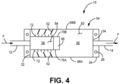
- FIG. 4 is a schematic top view of ducted smoke detector 10.
- FIGS. 2-4 are discussed together.
- FIG. 2 shows ducted smoke detector 10, air inlet 12, air outlet 14, base plate 24, housing 54, first housing end wall 32, second housing end wall 34, smoke sensing housing portion 56, particulate separator housing portion 58, interior partition wall 60, top walls 62 and 64, transition wall 66, side walls 68A and 70A, vent louvers 72, ribs 52, particulate separator 16, smoke sensing chamber 18, electronics 74, height H1, height H2, length L1, length L2, and airflow F.
- FIG. 1 shows ducted smoke detector 10, air inlet 12, air outlet 14, base plate 24, housing 54, first housing end wall 32, second housing end wall 34, smoke sensing housing portion 56, particulate separator housing portion 58, interior partition wall 60, top walls 62 and 64, transition wall 66, side walls
- FIG. 3 shows ducted smoke detector 10, air inlet 12, base plate 24, housing 54, first housing end wall 32, smoke sensing housing portion 56, particulate separator housing portion 58, interior partition wall 60, top walls 62 and 64, side walls 68A, 68B and 70A, 70B, vent louvers 72, ribs 52, mounting holes 26, particulate separator 16, smoke sensing chamber 18, electronics 74, width W1, and width W2.
- FIG. 1 shows ducted smoke detector 10, air inlet 12, base plate 24, housing 54, first housing end wall 32, smoke sensing housing portion 56, particulate separator housing portion 58, interior partition wall 60, top walls 62 and 64, side walls 68A, 68B and 70A, 70B, vent louvers 72, ribs 52, mounting holes 26, particulate separator 16, smoke sensing chamber 18, electronics 74, width W1, and width W2.
- ducted smoke detector 10 air inlet 12, air outlet 14, base plate 24, housing 54, first housing end wall 32, second housing end wall 34, smoke sensing housing portion 56, particulate separator housing portion 58, top walls 62 and 64, transition wall 66, side walls 68A, 68B and 70A, 70B, vent louvers 72, ribs 52, and airflow F.
- Reference to "top,” “sides,” “front,” “above” and other relative location terms used herein are provided to describe the illustrated ducted smoke detector 10 and do not denote an orientation of ducted smoke detector 10 in operation.
- Ducted smoke detector 10 can be mounted at any orientation.
- Housing 54 is disposed on base plate 24 and covers internal components of ducted smoke detector 10. Housing 54 and base plate 24 define the internal cavity of ducted smoke detector 10. Air inlet 12 extends outward from first housing end wall 32. Air outlet 14 extends outward from second housing end wall 34. Air inlet 12 and air outlet 14 are in fluid communication with the internal cavity ducted smoke detector 10. Particulate separator 16, smoke sensing chamber 18, and electronics (all shown in phantom in FIGS. 2 and 3 ) are disposed in the internal cavity and covered by housing 54.
- Housing 54 includes smoke sensing housing portion 56 and particulate separator housing portion 58.
- Particulate separator housing portion 58 is disposed on smoke sensing housing portion 56 and is open to smoke sensing housing portion 56.
- Particulate separator housing portion 58 houses particulate separator 16.
- Particulate separator housing portion 58 includes vent louvers 72. Vent louvers 72 can be disposed on opposite side walls 70A, 70B.
- Smoke sensing housing portion 56 houses smoke sensing chamber 18 and electronics 74 (i.e., circuitry for ducted smoke detector 10).
- internal partition wall 60 (shown in phantom in FIGS. 2 and 3 ) can be provided between particulate separator 16 and base plate 24 and electronics 74. Internal partition wall 60, together with particulate separator housing portion 58, can define a cavity for particulate separator 16. Internal partition wall 60 can extend a length of particulate separator 16 such that particulate separator housing portion 58 remains open to smoke sensing housing portion 56 aft of outlet end 42 of particulate separator 16. Internal partition wall 60 is attached to internal walls of particulate separator housing portion 58 and/or smoke sensing housing portion 56. Internal partition wall 60 can be curved between side walls 68A and 70A of particulate separator housing portion 58, as shown in FIG.3 .
- Internal partition wall 60 can be curved toward base plate 24, such that internal partition wall 60 forms a concave cavity for particulate separator 16. Internal partition wall 60 is spaced from particulate separator 16 to allow free rotation of particulate separator 16. Internal partition wall 60 can be provided to direct particulates 50 ejected from particulate separator 16 out of the internal cavity through vent louvers 72.
- Smoke sensing housing portion 56 extends from base plate 24 a first height H1 less than a total height H2 of housing 54.
- Smoke sensing housing portion 56 extends longitudinally between air inlet 12 and air outlet 14.
- Smoke sensing housing portion 56 extends a length L1 equal to a total length of housing 54.
- smoke sensing housing portion 56 can have a length L1 of approximately 6 to 7 inches (15.24 to 17.78 cm).
- Smoke sensing housing portion 56 extends between side walls 68A and 68B a width W1 equal to a total width of housing 54.
- Smoke sensing housing portion 56 can be rectangular.
- Top wall 62 is disposed above smoke sensing chamber 18, electronics 74, and base plate 24.
- Top wall 62 can be planar.
- Air outlet 14 is provided through second housing end wall 34 of smoke sensing housing portion 56. Air outlet 14 can be centrally located between side walls 68A and 68B. Air outlet 14 can be located at a desired height position on second housing end wall 34 to draw airflow through smoke sensing chamber 18.
- Particulate separator housing portion 58 extends outward from top wall 62 of smoke sensing housing portion 56 in a height direction.
- Smoke sensing housing portion 56 combined with particulate separator housing portion 58 extends from base plate 24 a height H2 equal to a total height of housing 54.
- the total height H1 can be approximately 3 inches (7.62 cm).
- Particulate separator housing portion 58 extends longitudinally from first housing end wall 32 toward second housing end wall 34.
- Particulate separator housing portion 58 extends a length L2 that is less than the length L1 of smoke sensing housing portion 56 or total length of housing 54.
- the length L2 of particulate separator housing portion 58 can be selected based on the length particulate separator 16 and position of particulate separator 16 relative to smoke sensing chamber 18 as further described herein.
- Particulate separator housing portion 58 extends between side walls 70A and 70B a width W2 less than the total width W1 of housing 54.
- Particulate separator housing portion 58 is centrally located between side walls 68A and 68B of smoke sensing housing portion 56.
- Particulate separator housing portion 58 has top wall 64 defining an outermost top wall of housing 54. Top wall 64 is disposed above particulate separator 16. Air inlet 12 is disposed through first housing end wall 32 of particulate separator housing portion 58. Air inlet 12 is centrally located between side walls 70A and 70B. Particulate separator housing portion 58 includes transition wall 66 disposed between side walls 70A and 70B opposite air inlet 12. Transition wall 66 extends from top wall 64 of particulate separator housing portion to top wall 62 of smoke sensing housing portion 56. Transition wall 66 is disposed aft of outlet end 42 of particulate separator 16. Transition wall 66 is angled between top wall 64 and top wall 62.
- Transition wall 66 slants from top wall 64 away from first housing end wall 32. Transition wall 66 is configured to direct airflow F exiting particulate separator 16 at outlet end 42 toward smoke sensing chamber 18.
- outlet end 42 and housing 54 e.g., transition wall 66
- Vent louvers 72 are provided on particulate separator housing portion 58. Vent louvers 72 provide openings through particulate separator housing portion 58. Vent louvers 72 can be slats or angled wall portions spaced along side walls 68A and 70A. Vent louvers 72 are angled to direct particulates 50 ejected from particulate separator 16 away from air inlet 12. Vent louvers 72 can be provided on side walls 70A, 70B and can extend orthogonal to base plate 24. Vent louvers 72 can extend a full or substantially full height of side walls 70A and 70B of particulate separator housing portion 58. Vent louvers 72 can be planar bodies that can be cast or co-molded with housing 54.
- Ribs 52 are disposed on top wall 62 of smoke sensing housing portion 56. Ribs 52 protrude outward from top wall 62 in a height direction. Ribs 52 are disposed adjacent to vent louvers 72. Ribs 52 are spaced along side walls 70A and 70B of particulate separator housing portion 58. Ribs 52 can extend between adjacent vent louvers 72. Ribs 52 can be provided in any suitable arrangement to entrain and direct particulates 50 ejected through vent louvers 72. The number of ribs 52 can be less than the number of vent louvers 72. Ribs 52 are angled walls configured to guide particulates 50 ejected through vent louvers 72 away from air inlet 12.
- Ribs 52 can extend from side walls 70A and 70B of smoke sensing housing portion 56 toward edges of vent louvers 72. Ribs 52 can extend at least up to edges of vent louvers 72. Ribs 52 can extend a full or partial height of side walls 70A and 70B as suitable for entraining and directing particulates 50. Ribs 52 can be planar bodies that can be cast or co-molded with housing 54.
- Housing 54 can be formed of any material suitable for containing internal components of ducted smoke detector 10. Housing 54 can be cast or molded as a unitary body or in multiple parts, which can be joined as known in the art. Generally, housing 54 includes smoke sensing housing portion 56 with top wall 62 disposed in close proximity to smoke sensing chamber 18 and particulate separator housing portion 58, extending outward from top wall 62 to provide additional space for particulate separator 16. As illustrated, particulate separator 16 can be disposed above smoke sensing chamber 18, however, other positions relative to smoke sensing chamber 18 within the internal cavity may be suitable. Vent louvers 72 are disposed adjacent to particulate separator 16 to direct particulates 50 ejected from particulate separator 16 out of ducted smoke detector 10 and away from air inlet 12. Ribs 52 can be provided to further direct particulates 50 away from air inlet 12. Housing 54 is not limited to the geometry shown. For example, housing 54 can have curved walls that more closely conform to the shape of internal components.
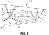
- FIG. 5 is a schematic perspective view of particulate separator 16. Particulate separator 16, perforated wall 38, inlet end 40, outlet end 42, holes 46, shaft 36, deflection vanes 48, struts 76, mounting brackets 78, housing 54, and airflow F are shown.
- FIG. 6 is a schematic perspective view of deflection vanes 48 in particulate separator 16. FIGS. 5 and 6 are discussed together herein.
- Particulate separator 16 includes perforated wall 38 having holes 46 of varying size and arranged around perforated wall 38 between inlet end 40 and outlet end 42 as previously described. Particulate separator 16 has inlet end 40 and an oppositely disposed outlet end 42. Inlet end 40 and outlet end 42 are open to airflow F.
- Perforated wall 38 is disposed around shaft 36 and configured to rotate with shaft 36. Perforated wall 38 can be connected to shaft 36 by struts 76, which can extend from perforated wall 38 to shaft 36. Struts 76 can be provided at inlet end 40 and outlet end 42. Struts 76 are arranged to maintain a radial position of perforated wall 38 relative to deflection vanes 48 and shaft 36.
- struts 76 can be provided at each of inlet end 40 and outlet end 42 as needed for structural stability. In the non-limiting example shown in FIG. 6 , three struts 76 can be uniformly spaced about shaft 36 at each of inlet end 40 and outlet end 42. In some embodiments, additional struts 76 can be provided at other locations along shaft 36.
- Particulate separator 16 is frustoconical in shape having a diameter that decreases from inlet end 40 to outlet end 42.
- Deflection vanes 48 can be configured to cause rotation of particulate separator 16 when acted on by airflow F.
- Deflection vanes 48 can have any shape, orientation, and arrangement suitable for driving a rotation of particulate separator 16 at a rate sufficient to force dust particulates 50 to perforated wall 38 and out holes 46
- Deflection vanes 48 can have any shape, orientation, and arrangement suitable for directing particulates 50 toward perforated wall 38 and out holes 46.
- rotation of particulate separator 16 can be motor-driven.
- Motor 53 shown schematically in FIG.
- Deflection vanes 48 can be disposed along shaft 36 from inlet end 40 to outlet end 42 or at multiple locations on shaft 36 at and/or between inlet end 40 and outlet end 42. Deflection vanes 48 are configured to allow airflow F, including smoke particulates, to pass through particulate separator 16, while driving separation of larger/heavier dust particulates 50 from airflow F and/or directing dust particulates 50 toward perforated wall 38 and out through holes 46.
- Deflection vanes 48 can capture airflow F at inlet end 40 and can drive rotation of particulate separator 16, simultaneously creating centrifugal and axial air currents, or can be configured to create centrifugal and axial air currents when driven by motor 53.
- the heavier particulates 50 e.g., 1-10 micron in size
- the smaller smoke particulates (e.g., less than 1 micron in size) in airflow F travel axially through particulate separator 16 and exit through outlet end 42 to smoke sensing chamber 18.
- Deflection vanes 48 can be arranged to provide a flow path along shaft 36 for airflow F that is substantially devoid of dust particles 50.
- Deflection vanes 48 extend a radial height or distance from shaft 36. Deflection vanes 48 can extend substantially to perforated wall 38. Deflection vanes 48 can be configured to have a near interference fit with perforated wall 38 to prevent dust particles 50 from becoming trapped between deflection vanes 48 and perforated wall 38. Deflection vanes 48 can be disposed at a desired pitch to capture airflow F and drive rotation of particulate separator 16. A smaller pitch and fewer deflection vanes 48 will typically result in a higher spin velocity while a larger and more aggressive pitch and more deflection vanes 48 will typically result in more torque and rotational force to project dust particulates 50 radially outward toward holes 46 of perforated wall 38.
- deflection vanes 48 extend the full length of particulate separator 16 from inlet end 40 to outlet end 42.
- the pitch will determine how many vane revolutions are provided along the length of shaft 36.
- the height and pitch of deflection vanes 48 can be modified based on inlet airflow F velocity and expected dust particulate 50 entrainment.
- Deflection vanes 48 function as a means for causing rotation of perforated wall 38 and balancing the centrifugal airflow velocity and the axial airflow velocity through particulate separator 16.
- deflection vanes 48 and the size and arrangement of holes 46 through perforated wall 38 can be selected for optimized particulate separation based on system application requirements, including but not limited to available air sources, expected contamination or particulate pollution, required smoke sensitivity, false alarm immunity, and maintenance requirements.
- Deflection vanes 48 and perforated wall 38 can be formed of any suitable lightweight material, including but not limited to aluminum.
- Shaft 36 extends outward from inlet end 40 and outlet end 42.
- Shaft 36 is rotatably connected to mounting brackets 78 at inlet end 40 and outlet end 42.
- Shaft 36 can be connected to mounting brackets 78 by a bearing (not shown) to allow shaft 36 to rotate relative to mounting brackets 78.
- Mounting brackets 78 connect particulate separator 16 to housing 54.
- Each mounting bracket 78 can be a triangular bracket that attaches to an inner surface of housing 54 in two locations.
- Mounting brackets 78 can be attached to an inner surface or top wall 64 (shown in FIGS. 2 and 3 ).
- Mounting brackets 78 are configured to maintain a position of particulate separator 16 in the internal cavity of ducted smoke detector 10.
- the disclosed ducted particulate smoke detector is designed to prevent clogging of the smoke detector chamber and thereby improve operability and reduce maintenance requirements.
- the disclosed dust particulate separator can minimize or eliminate the need for unscheduled smoke detector cleaning maintenance and allow the aircraft to maintain a higher level of operational readiness.
- any relative terms or terms of degree used herein such as “substantially”, “essentially”, “generally”, “approximately” and the like, should be interpreted in accordance with and subject to any applicable definitions or limits expressly stated herein.
- any relative terms or terms of degree used herein should be interpreted to broadly encompass any relevant disclosed embodiments as well as such ranges or variations as would be understood by a person of ordinary skill in the art in view of the entirety of the present disclosure, such as to encompass ordinary manufacturing tolerance variations, incidental alignment variations, transient alignment or shape variations induced by thermal, rotational or vibrational operational conditions, and the like.
- any relative terms or terms of degree used herein should be interpreted to encompass a range that expressly includes the designated quality, characteristic, parameter or value, without variation, as if no qualifying relative term or term of degree were utilized in the given disclosure or recitation.
- a ducted smoke detector includes a housing defining an interior cavity, an air inlet in fluid communication with the interior cavity, an air outlet in fluid communication with the interior cavity, a smoke sensing chamber disposed in the interior cavity, and a particulate separator disposed between and in fluid communication with the air inlet and the smoke sensing chamber in the interior cavity.
- the particulate separator includes a shaft, a perforated wall disposed around the shaft, and a plurality of deflection vanes disposed on the shaft.
- the perforated wall extends from a first open end to a second open end, is connected to the shaft, and is configured to rotate with the shaft.
- the plurality of deflection vanes is disposed on the shaft and extend radially outward toward the perforated wall, the plurality of deflection vanes configured to rotate with the shaft and the perforated wall.
- the ducted smoke detector of the preceding paragraph can optionally include, additionally and/or alternatively, any one or more of the following features, configurations and/or additional components:
- the housing can include a plurality of vent louvers in fluid communication with the interior cavity, the plurality of vent louvers disposed adjacent to the perforated wall of the particulate separator.
- the housing can include a plurality of ribs disposed on an exterior surface of the housing opposite the interior cavity, the plurality of ribs disposed adjacent to the plurality of vent louvers.
- ribs of the plurality of ribs can be angled from the vent louvers away from the air inlet.
- the perforated wall can have a frustoconical shape extending between the first open end and the second open end, wherein a diameter of the first open end is greater than a diameter of the second open end.
- deflection vanes of the plurality of deflection vanes can be disposed along the length of the shaft from the first open end to the second open end.
- the perforated wall includes holes of varying size disposed between the first open end and the second open end and wherein holes disposed adjacent to the first open end are larger than holes disposed adjacent to the second open end.
- the holes of the plurality of holes can be disposed around the particulate separator.
- a further embodiment of any of the foregoing ducted smoke detectors can further include a base plate connected to the housing, wherein the housing extends from the base plate to cover the interior cavity.
- the housing can include a smoke sensing housing portion extending over the smoke sensing chamber and the base plate at a first height from the base plate and a particulate separator housing portion extending over the particulate separator and base plate at a second height from the base plate with the second height being greater than the first height.
- vent louvers of the plurality of vent louvers can be disposed on the particulate separator housing portion and are angled away from the air inlet.
- vent louvers can be disposed on opposite sides of the particulate separator housing portion.
- the smoke sensing chamber can be disposed on the base plate and wherein the particulate separator is spaced from the base plate and disposed adjacent to a wall of the particulate separator housing portion facing the base plate.
- the particulate separator housing portion can extend outward from the second open end of the particulate separator toward the air outlet and slope toward the smoke sensing chamber to join the smoke sensing housing portion.
- the housing can further include an interior partition wall disposed between the particulate separator and the base plate and connected to at least one of the particulate separator housing portion and the smoke sensing housing portion.
- the interior partition wall can have a curved surface.
- the shaft can be rotatably mounted to interior walls of the housing.
- the air inlet can be disposed in the particulate separator housing portion and the air outlet can be disposed in the smoke sensing housing portion.
- the particulate separator housing portion can extend a first length from the air inlet toward the air outlet, the first length less than a total length of the housing, and the particulate separator housing portion can extend a first width less than a total width of the housing.
- the first open end of the particulate separator can be disposed adjacent to and aligned with the air inlet.
- the plurality of deflection vanes can be configured to drive rotation of the particulate separator when acted upon by an airflow received from the air inlet.
- a further embodiment of any of the foregoing ducted smoke detectors can further include a motor connected to the shaft and configured to drive rotation of the shaft.
Landscapes
- Chemical & Material Sciences (AREA)
- Engineering & Computer Science (AREA)
- Physics & Mathematics (AREA)
- General Physics & Mathematics (AREA)
- Health & Medical Sciences (AREA)
- Life Sciences & Earth Sciences (AREA)
- Analytical Chemistry (AREA)
- Medicinal Chemistry (AREA)
- Food Science & Technology (AREA)
- Biochemistry (AREA)
- General Health & Medical Sciences (AREA)
- Combustion & Propulsion (AREA)
- Immunology (AREA)
- Pathology (AREA)
- Computer Security & Cryptography (AREA)
- Business, Economics & Management (AREA)
- Emergency Management (AREA)
- Fire-Detection Mechanisms (AREA)
Abstract
Description
- The present disclosure is directed generally to smoke detectors and more particularly to ducted smoke detectors for use in an aircraft.
- Ducted smoke detectors are utilized on modern commercial aircraft to protect avionics bays of electronic controllers as well as air conditioner pack HEPA filters from thermal combustion. Ducted smoke detectors typically include a photo-electric smoke detector housed in a sealed enclosure with an inlet and exhaust duct port. The smoke detectors are disposed in an air return path that picks up dust particulates that can plug the ducted smoke detector, causing the smoke detector to become inoperable. Unscheduled maintenance is often required to remove and clean the smoke detector.
- New technologies are needed to remove dust particulates from ducted smoke detectors to improve reliability of the smoke detector and reduce maintenance requirements.
- A ducted smoke detector includes a housing defining an interior cavity, an air inlet in fluid communication with the interior cavity, an air outlet in fluid communication with the interior cavity, a smoke sensing chamber disposed in the interior cavity, and a particulate separator disposed between and in fluid communication with the air inlet and the smoke sensing chamber in the interior cavity. The particulate separator includes a shaft, a perforated wall disposed around the shaft, and a plurality of deflection vanes disposed on the shaft. The perforated wall extends from a first open end to a second open end, is connected to the shaft, and is configured to rotate with the shaft. The plurality of deflection vanes is disposed on the shaft and extend radially outward toward the perforated wall, the plurality of deflection vanes configured to rotate with the shaft and the perforated wall.
- The present summary is provided only by way of example, and not limitation. Other aspects of the present disclosure will be appreciated in view of the entirety of the present disclosure, including the entire text, claims and accompanying figures.
-
-
FIG. 1 is a schematic top view of an internal cavity of a ducted smoke detector having a dust particulate separator. -
FIG. 2 is a schematic side view of the ducted smoke detector. -
FIG. 3 is a schematic front view of the ducted smoke detector. -
FIG. 4 is a schematic top view of the ducted smoke detector. -
FIG. 5 is a schematic perspective view of the dust particulate separator. -
FIG. 6 is a schematic perspective view of vanes of the dust particulate separator. - While the above-identified figures set forth embodiments of the present invention, other embodiments are also contemplated, as noted in the discussion. In all cases, this disclosure presents the invention by way of representation and not limitation. It should be understood that numerous other modifications and embodiments can be devised by those skilled in the art, which fall within the scope and spirit of the principles of the invention. The figures may not be drawn to scale, and applications and embodiments of the present invention may include features, steps and/or components not specifically shown in the drawings.
- The present disclosure is directed to a ducted smoke detector for an aircraft. The ducted smoke detector includes a dust particulate separator at an air inlet to collect and disperse dust particulates outside a smoke detector chamber to prevent clogging of the smoke detector chamber. The disclosed dust particulate separator and associated features described herein can improve operability and reduce maintenance requirements of the ducted smoke detector. The disclosed dust particulate separator can minimize or eliminate the need for unscheduled smoke detector cleaning maintenance and allow the aircraft to maintain a higher level of operational readiness.
-
FIG. 1 is a schematic top view of an internal cavity of ductedsmoke detector 10.Air inlet 12,air outlet 14,particulate separator 16,smoke sensing chamber 18,first end 20,second end 22,base plate 24,mounting holes 26,inlet conduit 28, inlet expander 30, firsthousing end wall 32, secondhousing end wall 34,shaft 36, perforatedwall 38,inlet end 40,outlet end 42,holes 46, deflection vanes 48 (shown in phantom),particulates 50, ribs 52 (shown in phantom),motor 53, and airflow F are shown. Top walls of a housing are removed to show components of the internal cavity. - Ducted
smoke detector 10 is configured for use in an aircraft to protect avionics bays of electronic controllers as well as air conditioner pack HEPA filters from thermal combustion. Ductedsmoke detector 10 is a flow-through smoke detector configured to be disposed in an air conditioning air return path. A portion of the return air can be drawn through ductedsmoke detector 10 fromair inlet 12 toair outlet 14.Air inlet 12 is configured to receive a portion of the return air (airflow F), which includes particulates 50 (dust and other larger particles capable of clogging smoke sensing chamber 18).Air outlet 14 can be coupled to the air conditioning system.Particulate separator 16, in combination with additional features described herein, is configured to purgeparticulates 50 from airflow F received fromair inlet 12, such that the amount ofparticulates 50 reachingsmoke sensing chamber 18 is significantly reduced. - Ducted
smoke detector 10 extends longitudinally fromfirst end 20 tosecond end 22.Air inlet 12 is disposed atfirst end 20.Air outlet 14 is disposed atsecond end 22.Air inlet 12 extends through firsthousing end wall 32.Air outlet 14 extends through secondhousing end wall 34.Air inlet 12 can be longitudinally aligned withair outlet 14.Particulate separator 16 is disposed adjacent toair inlet 12.Inlet end 40 ofparticulate separator 16 is disposedadjacent air inlet 12.Outlet end 42 ofparticulate separator 16 facessmoke sensing chamber 18.Smoke sensing chamber 18 is disposed betweenparticulate separator 16 andair outlet 14.Particulate separator 16 andsmoke sensing chamber 18 can be aligned longitudinally withair inlet 12 andair outlet 14.Smoke sensing chamber 18 is disposed onbase plate 24.Base plate 24 includesmounting holes 26 configured for mounting ductedsmoke detector 10 to a surface.Base plate 24 additionally includes electronics (shown inFIGS. 2 and3 ) for operation of ductedsmoke detector 10. -
Air inlet 12 can includeinlet conduit 28 and inlet expander 30.Inlet conduit 28 extends outward from the internal cavity of ductedsmoke detector 10 and is in fluid communication with the internal cavity.Inlet conduit 28 is configured to direct airflow F into the internal cavity of ductedsmoke detector 10.Inlet expander 30 is disposed in the internal cavity at an end ofinlet conduit 28. Inlet expander 30 extends from firsthousing end wall 32 towardinlet end 40 ofparticulate separator 16.Inlet expander 30 is cylindrical having a diameter substantially matching a diameter ofparticulate separator 16 atinlet end 40.Inlet expander 30 is aligned withinlet end 40.Inlet expander 30 is configured to direct airflow F toparticulate separator 16.Inlet expander 30 is spaced fromparticulate separator 16 atinlet end 40 to allow rotation ofparticulate separator 16. In alternative embodiments,air inlet 12 can have a uniform diameter matching a diameter ofinlet end 40 ofparticulate separator 16. Inletend 40 ofparticulate separator 16 can be disposed adjacent to firsthousing end wall 32.Air inlet 12 can have any configuration suitable for directing airflow F entering ductedsmoke detector 10 intoparticulate separator 16 and preventing or limiting airflow F entering ductedsmoke detector 10 from bypassingparticulate separator 16. -
Particulate separator 16 includes perforatedwall 38,inlet end 40,outlet end 42,shaft 36, holes 46, and deflection vanes 48.Particulate separator 16 has a frustoconical shape defined byperforated wall 38 extending from and decreasing in diameter frominlet end 40 to outlet end 42.Inlet end 40 and outlet end 42 are open to airflowF. Perforated wall 38 is disposed aroundshaft 36 and configured to rotate withshaft 36. Perforatedwall 38 can be connected toshaft 36 by struts (shown inFIG. 6 ) and/or deflection vanes 48. Struts can extend fromperforated wall 38 toshaft 36, for example, atinlet end 40 andoutlet end 42.Deflection vanes 48 can extend radially outward fromshaft 36 towardperforated wall 38.Deflection vanes 48 can be disposed at varying locations along a length ofshaft 36 andperforated wall 38. As used herein, the term "deflection vanes" can refer to a single vane body with multiple revolutions aroundshaft 36, multiple vane bodies, or multiple vanes disposed at varying locations aroundshaft 36.Deflection vanes 48 can be configured to cause rotation ofparticulate separator 16 when airflow F is received inparticulate separator 16 fromair inlet 12. In some embodiments, rotation ofparticulate separator 16 can be additionally and/or alternatively driven by amotor 53, as described further herein. As discussed further herein,shaft 36 is rotatably mounted to a housing ofducted smoke detector 10.Optional motor 53 can be connected toshaft 36, for example atinlet end 40 as shown. - Perforated
wall 38 includes a plurality ofholes 46 of varying size. Hole size decreases alongperforated wall 38 frominlet end 40 to outlet end 42.Holes 46 disposed adjacent to inlet end 40 have a larger diameter thanholes 46 disposed adjacent to outlet end 42. Hole size can be selected to accommodate passage ofdust particulates 50, which can generally range from 1 to 10 microns.Holes 46 are disposed around a circumference ofperforated wall 38. In some embodiments, holes 46 can be provided in rings. In other embodiments, holes 46 can be provided with non-uniform or irregular spacing.Holes 46 are configured to expelparticulates 50 collected inparticulate separator 16. Asparticulate separator 16 rotates,particulates 50 are forced outward towardperforated wall 38 by centrifugal force. An air vortex is formed insideparticulate separator 16, which separatesparticulates 50 from airflow F and forcesparticulates 50 towardperforated wall 38 where they can be expelled throughholes 46. Heavier andlarger particulates 50 are forced outward first and can be expelled throughlarger holes 46 disposed at an upstream end ofparticulate separator 16 adjacent toinlet end 40. Lighter and smaller particles are expelled throughsmaller holes 46 in a downstream portion ofparticulate separator 16 adjacent to outlet end 42. The number, size, and location ofholes 46 can be selected to provide a desired reduction inparticulates 50 in airflow F atoutlet end 42. Smoke particles are approximately 1/10th the size ofdust particulates 50 and can remain entrained in airflow F at the center ofparticulate separator 16. Smoke particles can exit particulate separator atoutlet end 42. - Perforated
wall 38 can be formed of any suitable lightweight material, including but not limited to aluminum. Perforatedwall 38 can be formed, for example, from sheet metal.Holes 46 can be formed, for example, by drilling. In some embodiments,particulate separator 16 can have a length of approximately 3 inches (approximately 7.62 cm) with a 1-inch diameter (approximately 2.54 cm) opening atinlet end 40 and a 0.5-inch (approximately 1.27 cm) diameter opening atoutlet end 42. -
Particulates 50 expelled through perforatedwall 38 can be expelled fromducted smoke detector 10 through vent louvers (shown inFIGS. 2-4 ) in a housing ofducted smoke detector 10, as described further herein.Particulates 50 expelled through vent louvers can be guided away fromair inlet 12 by ribs 52 (shown in phantom) disposed on an external surface of the housing.Ribs 52 can be arranged to guide a flow ofparticulates 50 away fromair inlet 12 to preventparticulates 50 from enteringair inlet 12. For example,ribs 52 can be angled fromparticulate separator 16 away fromair inlet 12 such thatribs 52 are disposed at an obtuse angle α relative toair inlet 12. -
Outlet end 42 ofparticulate separator 16 is disposed upstream ofsmoke sensing chamber 18.Outlet end 42 can be spaced fromsmoke sensing chamber 18 to direct airflow F toward an upstream face ofsmoke sensor chamber 18. Ducting or housing can be configured to direct airflow F from outlet end 42 ofparticulate separator 16 towardsmoke sensing chamber 18. -
Smoke sensing chamber 18 receives airflow F fromparticulate separator 16.Smoke sensing chamber 18 is configured to detect smoke particles using technology known in the art.Smoke sensing chamber 18 includes a perforated screen (not shown) to preventdust particulates 50 from enteringsmoke sensing chamber 18. Smoke sensors are capable of optical discrimination to distinguish smoke particles fromdust particulates 50 that entersmoke sensing chamber 18.Smoke sensing chamber 18 is disposed onbase plate 24.Smoke sensing chamber 18 is disposed adjacent toair outlet 14. -
Ducted smoke detector 10 can be configured to detect airflow F throughducted smoke detector 10 and/or rotation ofparticulate separator 16.Ducted smoke detector 10 and/or controller device in communication with components ofducted smoke detector 10 can be configured to trigger an alarm if airflow F is insufficient to driveparticulate separator 16 and/or if rotation ofparticulate separator 16 has ceased. Ducted smoke detector can include one or more sensors (not shown) configured to detect airflow F and/or sense rotation ofparticulate separator 16. For example, airflow F throughducted smoke detector 10 can be detected and measured by a solid-state air flow sensor or other airflow sensing device known in the art. In other examples, airflow F can be determined based on a pressure differential betweeninlet end 40 and outlet end 42 using pressure sensors. In some examples, an optical encoder or other optical sensor can be used to detect rotation ofparticulate separator 16. For example, a device can be configured to detect a beam of light emitted throughparticulate separator 16, in a direction perpendicular to the axis of rotation, through alignedholes 46 disposed on opposite sides ofperforated wall 38. Intermittent or oscillating detection of the light beam will indicate rotation ofparticulate separator 16 as solid portions ofperforated wall 38 intermittently interrupts transmission. No detection or constant detection will indicate rotation has ceased. A slowing rate of detection can indicate rotation has slowed. In other examples, an element disposed directly onshaft 36 or perforatedwall 38 can be used to interrupt a beam of light. Other means for detecting airflow F and/or rotation ofparticulate separator 16 are contemplated. In some embodiments, an alarm indicating insufficient airflow F or rotation ofparticulate separator 16, detected by one or more sensors, can trigger operation ofmotor 53 to driveparticulate separator 16. -
FIG. 2 is a schematic side view ofducted smoke detector 10.FIG. 3 is a schematic front view ofducted smoke detector 10.FIG. 4 is a schematic top view ofducted smoke detector 10.FIGS. 2-4 are discussed together.FIG. 2 shows ductedsmoke detector 10,air inlet 12,air outlet 14,base plate 24,housing 54, firsthousing end wall 32, secondhousing end wall 34, smokesensing housing portion 56, particulateseparator housing portion 58,interior partition wall 60,top walls transition wall 66,side walls louvers 72,ribs 52,particulate separator 16,smoke sensing chamber 18,electronics 74, height H1, height H2, length L1, length L2, and airflow F.FIG. 3 shows ductedsmoke detector 10,air inlet 12,base plate 24,housing 54, firsthousing end wall 32, smokesensing housing portion 56, particulateseparator housing portion 58,interior partition wall 60,top walls side walls louvers 72,ribs 52, mountingholes 26,particulate separator 16,smoke sensing chamber 18,electronics 74, width W1, and width W2.FIG. 4 shows ductedsmoke detector 10,air inlet 12,air outlet 14,base plate 24,housing 54, firsthousing end wall 32, secondhousing end wall 34, smokesensing housing portion 56, particulateseparator housing portion 58,top walls transition wall 66,side walls louvers 72,ribs 52, and airflow F. Reference to "top," "sides," "front," "above" and other relative location terms used herein are provided to describe the illustratedducted smoke detector 10 and do not denote an orientation ofducted smoke detector 10 in operation.Ducted smoke detector 10 can be mounted at any orientation. -
Housing 54 is disposed onbase plate 24 and covers internal components ofducted smoke detector 10.Housing 54 andbase plate 24 define the internal cavity ofducted smoke detector 10.Air inlet 12 extends outward from firsthousing end wall 32.Air outlet 14 extends outward from secondhousing end wall 34.Air inlet 12 andair outlet 14 are in fluid communication with the internal cavity ductedsmoke detector 10.Particulate separator 16,smoke sensing chamber 18, and electronics (all shown in phantom inFIGS. 2 and3 ) are disposed in the internal cavity and covered byhousing 54. -
Housing 54 includes smokesensing housing portion 56 and particulateseparator housing portion 58. Particulateseparator housing portion 58 is disposed on smokesensing housing portion 56 and is open to smoke sensinghousing portion 56. Particulateseparator housing portion 58 housesparticulate separator 16. Particulateseparator housing portion 58 includesvent louvers 72.Vent louvers 72 can be disposed onopposite side walls sensing housing portion 56 houses smoke sensingchamber 18 and electronics 74 (i.e., circuitry for ducted smoke detector 10). - In some embodiments, internal partition wall 60 (shown in phantom in
FIGS. 2 and3 ) can be provided betweenparticulate separator 16 andbase plate 24 andelectronics 74.Internal partition wall 60, together with particulateseparator housing portion 58, can define a cavity forparticulate separator 16.Internal partition wall 60 can extend a length ofparticulate separator 16 such that particulateseparator housing portion 58 remains open to smokesensing housing portion 56 aft of outlet end 42 ofparticulate separator 16.Internal partition wall 60 is attached to internal walls of particulateseparator housing portion 58 and/or smokesensing housing portion 56.Internal partition wall 60 can be curved betweenside walls separator housing portion 58, as shown inFIG.3 .Internal partition wall 60 can be curved towardbase plate 24, such thatinternal partition wall 60 forms a concave cavity forparticulate separator 16.Internal partition wall 60 is spaced fromparticulate separator 16 to allow free rotation ofparticulate separator 16.Internal partition wall 60 can be provided todirect particulates 50 ejected fromparticulate separator 16 out of the internal cavity throughvent louvers 72. - Smoke
sensing housing portion 56 extends from base plate 24 a first height H1 less than a total height H2 ofhousing 54. Smokesensing housing portion 56 extends longitudinally betweenair inlet 12 andair outlet 14. Smokesensing housing portion 56 extends a length L1 equal to a total length ofhousing 54. In some embodiments, smokesensing housing portion 56 can have a length L1 of approximately 6 to 7 inches (15.24 to 17.78 cm). Smokesensing housing portion 56 extends betweenside walls housing 54. Smokesensing housing portion 56 can be rectangular.Top wall 62 is disposed abovesmoke sensing chamber 18,electronics 74, andbase plate 24.Top wall 62 can be planar.Air outlet 14 is provided through secondhousing end wall 34 of smokesensing housing portion 56.Air outlet 14 can be centrally located betweenside walls Air outlet 14 can be located at a desired height position on secondhousing end wall 34 to draw airflow throughsmoke sensing chamber 18. - Particulate
separator housing portion 58 extends outward fromtop wall 62 of smokesensing housing portion 56 in a height direction. Smokesensing housing portion 56 combined with particulateseparator housing portion 58 extends from base plate 24 a height H2 equal to a total height ofhousing 54. In some embodiments, the total height H1 can be approximately 3 inches (7.62 cm). Particulateseparator housing portion 58 extends longitudinally from firsthousing end wall 32 toward secondhousing end wall 34. Particulateseparator housing portion 58 extends a length L2 that is less than the length L1 of smokesensing housing portion 56 or total length ofhousing 54. The length L2 of particulateseparator housing portion 58 can be selected based on the lengthparticulate separator 16 and position ofparticulate separator 16 relative to smoke sensingchamber 18 as further described herein. Particulateseparator housing portion 58 extends betweenside walls housing 54. Particulateseparator housing portion 58 is centrally located betweenside walls sensing housing portion 56. - Particulate
separator housing portion 58 hastop wall 64 defining an outermost top wall ofhousing 54.Top wall 64 is disposed aboveparticulate separator 16.Air inlet 12 is disposed through firsthousing end wall 32 of particulateseparator housing portion 58.Air inlet 12 is centrally located betweenside walls separator housing portion 58 includestransition wall 66 disposed betweenside walls opposite air inlet 12.Transition wall 66 extends fromtop wall 64 of particulate separator housing portion totop wall 62 of smokesensing housing portion 56.Transition wall 66 is disposed aft of outlet end 42 ofparticulate separator 16.Transition wall 66 is angled betweentop wall 64 andtop wall 62.Transition wall 66 slants fromtop wall 64 away from firsthousing end wall 32.Transition wall 66 is configured to direct airflow F exitingparticulate separator 16 atoutlet end 42 towardsmoke sensing chamber 18. Preferably,outlet end 42 and housing 54 (e.g., transition wall 66) are configured to direct airflow F toward a side face ofsmoke sensing chamber 18. -
Vent louvers 72 are provided on particulateseparator housing portion 58.Vent louvers 72 provide openings through particulateseparator housing portion 58.Vent louvers 72 can be slats or angled wall portions spaced alongside walls Vent louvers 72 are angled todirect particulates 50 ejected fromparticulate separator 16 away fromair inlet 12.Vent louvers 72 can be provided onside walls base plate 24.Vent louvers 72 can extend a full or substantially full height ofside walls separator housing portion 58.Vent louvers 72 can be planar bodies that can be cast or co-molded withhousing 54. -
Ribs 52 are disposed ontop wall 62 of smokesensing housing portion 56.Ribs 52 protrude outward fromtop wall 62 in a height direction.Ribs 52 are disposed adjacent to ventlouvers 72.Ribs 52 are spaced alongside walls separator housing portion 58.Ribs 52 can extend betweenadjacent vent louvers 72.Ribs 52 can be provided in any suitable arrangement to entrain anddirect particulates 50 ejected throughvent louvers 72. The number ofribs 52 can be less than the number ofvent louvers 72.Ribs 52 are angled walls configured to guideparticulates 50 ejected throughvent louvers 72 away fromair inlet 12.Ribs 52 can extend fromside walls sensing housing portion 56 toward edges ofvent louvers 72.Ribs 52 can extend at least up to edges ofvent louvers 72.Ribs 52 can extend a full or partial height ofside walls particulates 50.Ribs 52 can be planar bodies that can be cast or co-molded withhousing 54. -
Housing 54 can be formed of any material suitable for containing internal components ofducted smoke detector 10.Housing 54 can be cast or molded as a unitary body or in multiple parts, which can be joined as known in the art. Generally,housing 54 includes smokesensing housing portion 56 withtop wall 62 disposed in close proximity to smoke sensingchamber 18 and particulateseparator housing portion 58, extending outward fromtop wall 62 to provide additional space forparticulate separator 16. As illustrated,particulate separator 16 can be disposed abovesmoke sensing chamber 18, however, other positions relative to smoke sensingchamber 18 within the internal cavity may be suitable.Vent louvers 72 are disposed adjacent toparticulate separator 16 to directparticulates 50 ejected fromparticulate separator 16 out ofducted smoke detector 10 and away fromair inlet 12.Ribs 52 can be provided to furtherdirect particulates 50 away fromair inlet 12.Housing 54 is not limited to the geometry shown. For example,housing 54 can have curved walls that more closely conform to the shape of internal components. -
FIG. 5 is a schematic perspective view ofparticulate separator 16.Particulate separator 16, perforatedwall 38,inlet end 40,outlet end 42, holes 46,shaft 36,deflection vanes 48, struts 76, mountingbrackets 78,housing 54, and airflow F are shown.FIG. 6 is a schematic perspective view ofdeflection vanes 48 inparticulate separator 16.FIGS. 5 and6 are discussed together herein. -
Particulate separator 16 includes perforatedwall 38 havingholes 46 of varying size and arranged around perforatedwall 38 betweeninlet end 40 and outlet end 42 as previously described.Particulate separator 16 hasinlet end 40 and an oppositely disposedoutlet end 42.Inlet end 40 and outlet end 42 are open to airflowF. Perforated wall 38 is disposed aroundshaft 36 and configured to rotate withshaft 36. Perforatedwall 38 can be connected toshaft 36 bystruts 76, which can extend fromperforated wall 38 toshaft 36.Struts 76 can be provided atinlet end 40 andoutlet end 42.Struts 76 are arranged to maintain a radial position ofperforated wall 38 relative todeflection vanes 48 andshaft 36. Any number and arrangement ofstruts 76 can be provided at each ofinlet end 40 and outlet end 42 as needed for structural stability. In the non-limiting example shown inFIG. 6 , threestruts 76 can be uniformly spaced aboutshaft 36 at each ofinlet end 40 andoutlet end 42. In some embodiments,additional struts 76 can be provided at other locations alongshaft 36. -
Particulate separator 16 is frustoconical in shape having a diameter that decreases frominlet end 40 to outlet end 42.Deflection vanes 48 can be configured to cause rotation ofparticulate separator 16 when acted on by airflowF. Deflection vanes 48 can have any shape, orientation, and arrangement suitable for driving a rotation ofparticulate separator 16 at a rate sufficient to forcedust particulates 50 toperforated wall 38 and outholes 46Deflection vanes 48 can have any shape, orientation, and arrangement suitable for directingparticulates 50 towardperforated wall 38 and out holes 46. In some embodiments, rotation ofparticulate separator 16 can be motor-driven. Motor 53 (shown schematically inFIG. 1 ) can act as the sole driver forparticulate separator 16 or as an assist if airflow F drawn throughparticulate separator 16 is insufficient to cause rotation ofparticulate separator 16 via deflection vanes 48.Deflection vanes 48 can be disposed alongshaft 36 frominlet end 40 to outlet end 42 or at multiple locations onshaft 36 at and/or betweeninlet end 40 andoutlet end 42.Deflection vanes 48 are configured to allow airflow F, including smoke particulates, to pass throughparticulate separator 16, while driving separation of larger/heavier dust particulates 50 from airflow F and/or directingdust particulates 50 towardperforated wall 38 and out through holes 46. -
Deflection vanes 48 can capture airflow F atinlet end 40 and can drive rotation ofparticulate separator 16, simultaneously creating centrifugal and axial air currents, or can be configured to create centrifugal and axial air currents when driven bymotor 53. The heavier particulates 50 (e.g., 1-10 micron in size) in airflow F are forced radially outward toperforated wall 38 where they can tumble before being ejected out ofparticulate separator 16 throughholes 46 inperforated wall 38. The smaller smoke particulates (e.g., less than 1 micron in size) in airflow F travel axially throughparticulate separator 16 and exit throughoutlet end 42 to smoke sensingchamber 18.Deflection vanes 48 can be arranged to provide a flow path alongshaft 36 for airflow F that is substantially devoid ofdust particles 50. -
Deflection vanes 48 extend a radial height or distance fromshaft 36.Deflection vanes 48 can extend substantially toperforated wall 38.Deflection vanes 48 can be configured to have a near interference fit withperforated wall 38 to preventdust particles 50 from becoming trapped betweendeflection vanes 48 andperforated wall 38.Deflection vanes 48 can be disposed at a desired pitch to capture airflow F and drive rotation ofparticulate separator 16. A smaller pitch andfewer deflection vanes 48 will typically result in a higher spin velocity while a larger and more aggressive pitch andmore deflection vanes 48 will typically result in more torque and rotational force to projectdust particulates 50 radially outward towardholes 46 ofperforated wall 38. Preferably,deflection vanes 48 extend the full length ofparticulate separator 16 frominlet end 40 to outlet end 42. The pitch will determine how many vane revolutions are provided along the length ofshaft 36. The height and pitch ofdeflection vanes 48 can be modified based on inlet airflow F velocity and expecteddust particulate 50 entrainment.Deflection vanes 48 function as a means for causing rotation ofperforated wall 38 and balancing the centrifugal airflow velocity and the axial airflow velocity throughparticulate separator 16. The configuration and arrangement ofdeflection vanes 48 and the size and arrangement ofholes 46 throughperforated wall 38 can be selected for optimized particulate separation based on system application requirements, including but not limited to available air sources, expected contamination or particulate pollution, required smoke sensitivity, false alarm immunity, and maintenance requirements.Deflection vanes 48 andperforated wall 38 can be formed of any suitable lightweight material, including but not limited to aluminum. -
Shaft 36 extends outward frominlet end 40 andoutlet end 42.Shaft 36 is rotatably connected to mountingbrackets 78 atinlet end 40 andoutlet end 42.Shaft 36 can be connected to mountingbrackets 78 by a bearing (not shown) to allowshaft 36 to rotate relative to mountingbrackets 78. Mountingbrackets 78 connectparticulate separator 16 tohousing 54. Each mountingbracket 78 can be a triangular bracket that attaches to an inner surface ofhousing 54 in two locations. Mountingbrackets 78 can be attached to an inner surface or top wall 64 (shown inFIGS. 2 and3 ). Mountingbrackets 78 are configured to maintain a position ofparticulate separator 16 in the internal cavity ofducted smoke detector 10. - The disclosed ducted particulate smoke detector is designed to prevent clogging of the smoke detector chamber and thereby improve operability and reduce maintenance requirements. The disclosed dust particulate separator can minimize or eliminate the need for unscheduled smoke detector cleaning maintenance and allow the aircraft to maintain a higher level of operational readiness.
- The embodiments disclosed herein are intended to provide an explanation of the present invention and not a limitation of the invention. The present invention is not limited to the embodiments disclosed. It will be understood by one skilled in the art that various modifications and variations can be made to the invention without departing from the scope and spirit of the invention.
- Any relative terms or terms of degree used herein, such as "substantially", "essentially", "generally", "approximately" and the like, should be interpreted in accordance with and subject to any applicable definitions or limits expressly stated herein. In all instances, any relative terms or terms of degree used herein should be interpreted to broadly encompass any relevant disclosed embodiments as well as such ranges or variations as would be understood by a person of ordinary skill in the art in view of the entirety of the present disclosure, such as to encompass ordinary manufacturing tolerance variations, incidental alignment variations, transient alignment or shape variations induced by thermal, rotational or vibrational operational conditions, and the like. Moreover, any relative terms or terms of degree used herein should be interpreted to encompass a range that expressly includes the designated quality, characteristic, parameter or value, without variation, as if no qualifying relative term or term of degree were utilized in the given disclosure or recitation.
- The following are non-exclusive descriptions of possible embodiments of the present invention.
- A ducted smoke detector includes a housing defining an interior cavity, an air inlet in fluid communication with the interior cavity, an air outlet in fluid communication with the interior cavity, a smoke sensing chamber disposed in the interior cavity, and a particulate separator disposed between and in fluid communication with the air inlet and the smoke sensing chamber in the interior cavity. The particulate separator includes a shaft, a perforated wall disposed around the shaft, and a plurality of deflection vanes disposed on the shaft. The perforated wall extends from a first open end to a second open end, is connected to the shaft, and is configured to rotate with the shaft. The plurality of deflection vanes is disposed on the shaft and extend radially outward toward the perforated wall, the plurality of deflection vanes configured to rotate with the shaft and the perforated wall.
- The ducted smoke detector of the preceding paragraph can optionally include, additionally and/or alternatively, any one or more of the following features, configurations and/or additional components:
In a further embodiment of the foregoing ducted smoke detector, the housing can include a plurality of vent louvers in fluid communication with the interior cavity, the plurality of vent louvers disposed adjacent to the perforated wall of the particulate separator. - In a further embodiment of any of the foregoing ducted smoke detectors, the housing can include a plurality of ribs disposed on an exterior surface of the housing opposite the interior cavity, the plurality of ribs disposed adjacent to the plurality of vent louvers.
- In a further embodiment of any of the foregoing ducted smoke detectors, ribs of the plurality of ribs can be angled from the vent louvers away from the air inlet.
- In a further embodiment of any of the foregoing ducted smoke detectors, the perforated wall can have a frustoconical shape extending between the first open end and the second open end, wherein a diameter of the first open end is greater than a diameter of the second open end.
- In a further embodiment of any of the foregoing ducted smoke detectors, deflection vanes of the plurality of deflection vanes can be disposed along the length of the shaft from the first open end to the second open end.
- In a further embodiment of any of the foregoing ducted smoke detectors, the perforated wall includes holes of varying size disposed between the first open end and the second open end and wherein holes disposed adjacent to the first open end are larger than holes disposed adjacent to the second open end.
- In a further embodiment of any of the foregoing ducted smoke detectors, the holes of the plurality of holes can be disposed around the particulate separator.
- A further embodiment of any of the foregoing ducted smoke detectors can further include a base plate connected to the housing, wherein the housing extends from the base plate to cover the interior cavity.
- In a further embodiment of any of the foregoing ducted smoke detectors, the housing can include a smoke sensing housing portion extending over the smoke sensing chamber and the base plate at a first height from the base plate and a particulate separator housing portion extending over the particulate separator and base plate at a second height from the base plate with the second height being greater than the first height.
- In a further embodiment of any of the foregoing ducted smoke detectors, vent louvers of the plurality of vent louvers can be disposed on the particulate separator housing portion and are angled away from the air inlet.
- In a further embodiment of any of the foregoing ducted smoke detectors, the vent louvers can be disposed on opposite sides of the particulate separator housing portion.
- In a further embodiment of any of the foregoing ducted smoke detectors, the smoke sensing chamber can be disposed on the base plate and wherein the particulate separator is spaced from the base plate and disposed adjacent to a wall of the particulate separator housing portion facing the base plate.
- In a further embodiment of any of the foregoing ducted smoke detectors, the particulate separator housing portion can extend outward from the second open end of the particulate separator toward the air outlet and slope toward the smoke sensing chamber to join the smoke sensing housing portion.
- In a further embodiment of any of the foregoing ducted smoke detectors, the housing can further include an interior partition wall disposed between the particulate separator and the base plate and connected to at least one of the particulate separator housing portion and the smoke sensing housing portion.
- In a further embodiment of any of the foregoing ducted smoke detectors, the interior partition wall can have a curved surface.
- In a further embodiment of any of the foregoing ducted smoke detectors, the shaft can be rotatably mounted to interior walls of the housing.
- In a further embodiment of any of the foregoing ducted smoke detectors, the air inlet can be disposed in the particulate separator housing portion and the air outlet can be disposed in the smoke sensing housing portion.
- In a further embodiment of any of the foregoing ducted smoke detectors, the particulate separator housing portion can extend a first length from the air inlet toward the air outlet, the first length less than a total length of the housing, and the particulate separator housing portion can extend a first width less than a total width of the housing.
- In a further embodiment of any of the foregoing ducted smoke detectors, the first open end of the particulate separator can be disposed adjacent to and aligned with the air inlet.
- In a further embodiment of any of the foregoing ducted smoke detectors, the plurality of deflection vanes can be configured to drive rotation of the particulate separator when acted upon by an airflow received from the air inlet.
- A further embodiment of any of the foregoing ducted smoke detectors can further include a motor connected to the shaft and configured to drive rotation of the shaft.
- While the invention has been described with reference to an exemplary embodiment(s), it will be understood by those skilled in the art that various changes may be made, and equivalents may be substituted for elements thereof without departing from the scope of the invention. In addition, many modifications may be made to adapt a particular situation or material to the teachings of the invention without departing from the essential scope thereof. Therefore, it is intended that the invention not be limited to the particular embodiment(s) disclosed, but that the invention will include all embodiments falling within the scope of the appended claims.
Claims (15)
- A ducted smoke detector comprising:a housing defining an interior cavity;an air inlet in fluid communication with the interior cavity;an air outlet in fluid communication with the interior cavity;a smoke sensing chamber disposed in the interior cavity; anda particulate separator disposed between and in fluid communication with the air inlet and the smoke sensing chamber in the interior cavity, the particulate separator comprising:a shaft;a perforated wall disposed around the shaft and extending from a first open end to a second open end, the perforated wall connected to the shaft and configured to rotate with the shaft; anda plurality of deflection vanes disposed on the shaft and extending radially outward toward the perforated wall, the plurality of deflection vanes configured to rotate with the shaft and the perforated wall.
- The ducted smoke detector of claim 1, wherein the housing comprises a plurality of vent louvers in fluid communication with the interior cavity, the plurality of vent louvers disposed adjacent to the perforated wall of the particulate separator.
- The ducted smoke detector of claim 2, wherein the housing comprises a plurality of ribs disposed on an exterior surface of the housing opposite the interior cavity, the plurality of ribs disposed adjacent to the plurality of vent louvers.
- The ducted smoke detector of claim 3, wherein ribs of the plurality of ribs are angled from the vent louvers away from the air inlet.
- The ducted smoke detector of any preceding claim, wherein the perforated wall has a frustoconical shape extending between the first open end and the second open end, wherein a diameter of the first open end is greater than a diameter of the second open end.
- The ducted smoke detector of any preceding claim, wherein deflection vanes of the plurality of deflection vanes are disposed along a length of the shaft from the first open end to the second open end.
- The ducted smoke detector of any preceding claim, wherein the perforated wall comprises holes of varying size disposed between the first open end and the second open end, wherein holes disposed adjacent to the first open end are larger than holes disposed adjacent to the second open end.
- The ducted smoke detector of any preceding claim, and further comprising a base plate connected to the housing, wherein the housing extends from the base plate to cover the interior cavity;
wherein the housing comprises: a smoke sensing housing portion extending over the smoke sensing chamber and the base plate at a first height from the base plate; and a particulate separator housing portion extending over the particulate separator and base plate at a second height from the base plate, wherein the second height is greater than the first height. - The ducted smoke detector of claim 8, wherein the housing comprises a plurality of vent louvers in fluid communication with the interior cavity, the plurality of vent louvers disposed adjacent to the perforated wall of the particulate separator; and wherein vent louvers of the plurality of vent louvers are disposed on the particulate separator housing portion and are angled away from the air inlet;
optionally, wherein the vent louvers are disposed on opposite sides of the particulate separator housing portion. - The ducted smoke detector of claim 8 or 9, wherein the smoke sensing chamber is disposed on the base plate and wherein the particulate separator is spaced from the base plate and disposed adjacent to a wall of the particulate separator housing portion facing the base plate.
- The ducted smoke detector of any one of claims 8-10, wherein the particulate separator housing portion extends outward from the second open end of the particulate separator toward the air outlet and slopes toward the smoke sensing chamber to join the smoke sensing housing portion.
- The ducted smoke detector of any one of claims 8-11, wherein the housing further comprises an interior partition wall disposed between the particulate separator and the base plate and connected to at least one of the particulate separator housing portion and the smoke sensing housing portion.
- The ducted smoke detector of claim 12, wherein the interior partition wall has a curved surface.
- The ducted smoke detector of any one of claims 8-13, wherein the air inlet is disposed in the particulate separator housing portion and wherein the air outlet is disposed in the smoke sensing housing portion; and/or
wherein the particulate separator housing portion extends a first length from the air inlet toward the air outlet, the first length less than a total length of the housing, and wherein the particulate separator housing portion extends a first width less than a total width of the housing. - The ducted smoke detector of any preceding claim, wherein the plurality of deflection vanes is configured to drive rotation of the particulate separator when acted upon by an airflow received from the air inlet; and/orwherein the first open end of the particulate separator is disposed adjacent to and aligned with the air inlet; and/orwherein the shaft is rotatably mounted to interior walls of the housing.
Applications Claiming Priority (1)
| Application Number | Priority Date | Filing Date | Title |
|---|---|---|---|
| US18/198,450 US12345691B2 (en) | 2023-05-17 | 2023-05-17 | Dust particulate separator for ducted smoke detectors |
Publications (1)
| Publication Number | Publication Date |
|---|---|
| EP4465270A1 true EP4465270A1 (en) | 2024-11-20 |
Family
ID=91185155
Family Applications (1)
| Application Number | Title | Priority Date | Filing Date |
|---|---|---|---|
| EP24176654.2A Pending EP4465270A1 (en) | 2023-05-17 | 2024-05-17 | Dust particulate separator for ducted smoke detectors |
Country Status (2)
| Country | Link |
|---|---|
| US (1) | US12345691B2 (en) |
| EP (1) | EP4465270A1 (en) |
Citations (4)
| Publication number | Priority date | Publication date | Assignee | Title |
|---|---|---|---|---|
| US4245396A (en) * | 1979-07-09 | 1981-01-20 | Uop Inc. | Process for drying and granulating sewage sludge |
| WO2002003845A1 (en) * | 2000-07-06 | 2002-01-17 | John Herbert North | Improved air/particle separator |
| EP2320398A1 (en) * | 2009-10-28 | 2011-05-11 | Honeywell International Inc. | Fire sensor and method of detecting fire |
| US20120031200A1 (en) * | 2009-04-01 | 2012-02-09 | Nobuaki Ito | Device and method for continuously measuring horizontal flux of dustfall in atmosphere |
Family Cites Families (6)
| Publication number | Priority date | Publication date | Assignee | Title |
|---|---|---|---|---|
| US3930802A (en) * | 1974-09-16 | 1976-01-06 | Beasley Albert W | Industrial waste gas incinerator |
| US20010035462A1 (en) * | 2000-05-01 | 2001-11-01 | Jonathan Collazo | HVAC safety shutoff system |
| US7669457B2 (en) | 2007-07-24 | 2010-03-02 | Honeywell International Inc. | Apparatus and method of smoke detection |
| FR2991772B1 (en) | 2012-06-06 | 2016-05-06 | Bruno Aubert | METHOD FOR CONTINUOUSLY MEASURING AND NON-MAINTENANCE OF PARTICLES IN AIR AND ASSOCIATED DEVICE |
| CN104749004A (en) | 2015-04-01 | 2015-07-01 | 山西大同大学 | Gas sampler capable of removing dust |
| WO2018024984A1 (en) | 2016-08-02 | 2018-02-08 | Finsecur | Detector of smoke, gas or particles; system and method for detecting smoke, gas or particles |
-
2023
- 2023-05-17 US US18/198,450 patent/US12345691B2/en active Active
-
2024
- 2024-05-17 EP EP24176654.2A patent/EP4465270A1/en active Pending
Patent Citations (4)
| Publication number | Priority date | Publication date | Assignee | Title |
|---|---|---|---|---|
| US4245396A (en) * | 1979-07-09 | 1981-01-20 | Uop Inc. | Process for drying and granulating sewage sludge |
| WO2002003845A1 (en) * | 2000-07-06 | 2002-01-17 | John Herbert North | Improved air/particle separator |
| US20120031200A1 (en) * | 2009-04-01 | 2012-02-09 | Nobuaki Ito | Device and method for continuously measuring horizontal flux of dustfall in atmosphere |
| EP2320398A1 (en) * | 2009-10-28 | 2011-05-11 | Honeywell International Inc. | Fire sensor and method of detecting fire |
Also Published As
| Publication number | Publication date |
|---|---|
| US12345691B2 (en) | 2025-07-01 |
| US20240385160A1 (en) | 2024-11-21 |
Similar Documents
| Publication | Publication Date | Title |
|---|---|---|
| EP2509484B1 (en) | Vacuum cleaner | |
| EP2949912B1 (en) | System and method for controlling an electric aspirator of an air intake system for a work vehicle | |
| EP2221787B1 (en) | Smoke detector | |
| CA1144876A (en) | Fluid/particle separator unit | |
| CN102054324B (en) | Fire sensor and method of detecting fire | |
| EP2937030B1 (en) | Cyclonic separation device | |
| EP2500883B1 (en) | High sensitivity and high false alarm immunity optical smoke detector | |
| CA2648736A1 (en) | Dust separation system for use with mobile equipment | |
| CN101540088B (en) | Smoke detector | |
| EP1261269B1 (en) | Separator for vacuum cleaner | |
| KR20200079810A (en) | Apparatus and system for evaluating dust removal performance of road dust cleaning vehicles | |
| JPS62128817A (en) | Air conditioner for car | |
| US12345691B2 (en) | Dust particulate separator for ducted smoke detectors | |
| KR102740404B1 (en) | Multi-functional Sensor for Car | |
| US7497897B2 (en) | Air supply device for the passenger cell of a motor vehicle | |
| KR102342845B1 (en) | Particle collecting apparatus of cyclone type | |
| US6293751B1 (en) | Water/solids extracting blower | |
| JP3362236B2 (en) | Filter device | |
| RU2050940C1 (en) | Dust separator | |
| JP5026320B2 (en) | smoke detector | |
| KR20010001225U (en) | structure for discharge of pollutant in cyclone dust collector | |
| JP2026037552A (en) | smoke detector | |
| KR20010001211A (en) | Cyclone dust collector | |
| HK1051307B (en) | Separator for vacuum cleaner | |
| KR20110048374A (en) | robotic vacuum |
Legal Events
| Date | Code | Title | Description |
|---|---|---|---|
| PUAI | Public reference made under article 153(3) epc to a published international application that has entered the european phase |
Free format text: ORIGINAL CODE: 0009012 |
|
| STAA | Information on the status of an ep patent application or granted ep patent |
Free format text: STATUS: THE APPLICATION HAS BEEN PUBLISHED |
|
| AK | Designated contracting states |
Kind code of ref document: A1 Designated state(s): AL AT BE BG CH CY CZ DE DK EE ES FI FR GB GR HR HU IE IS IT LI LT LU LV MC ME MK MT NL NO PL PT RO RS SE SI SK SM TR |
|
| STAA | Information on the status of an ep patent application or granted ep patent |
Free format text: STATUS: REQUEST FOR EXAMINATION WAS MADE |
|
| 17P | Request for examination filed |
Effective date: 20250506 |
|
| STAA | Information on the status of an ep patent application or granted ep patent |
Free format text: STATUS: EXAMINATION IS IN PROGRESS |
|
| 17Q | First examination report despatched |
Effective date: 20250901 |
|
| GRAP | Despatch of communication of intention to grant a patent |
Free format text: ORIGINAL CODE: EPIDOSNIGR1 |
|
| STAA | Information on the status of an ep patent application or granted ep patent |
Free format text: STATUS: GRANT OF PATENT IS INTENDED |
|
| RIC1 | Information provided on ipc code assigned before grant |
Ipc: G08B 17/113 20060101AFI20260617BHEP Ipc: G08B 29/18 20060101ALI20260617BHEP Ipc: G01N 1/22 20060101ALI20260617BHEP Ipc: G01N 21/47 20060101ALN20260617BHEP |
|
| RIC1 | Information provided on ipc code assigned before grant |
Ipc: G08B 17/113 20060101AFI20260702BHEP Ipc: G08B 29/18 20060101ALI20260702BHEP Ipc: G01N 1/22 20060101ALI20260702BHEP Ipc: G01N 21/47 20060101ALN20260702BHEP |