EP4465257A1 - Vehicle passenger safety by height estimation - Google Patents
Vehicle passenger safety by height estimation Download PDFInfo
- Publication number
- EP4465257A1 EP4465257A1 EP23174323.8A EP23174323A EP4465257A1 EP 4465257 A1 EP4465257 A1 EP 4465257A1 EP 23174323 A EP23174323 A EP 23174323A EP 4465257 A1 EP4465257 A1 EP 4465257A1
- Authority
- EP
- European Patent Office
- Prior art keywords
- height
- person
- determining
- vehicle
- images
- Prior art date
- Legal status (The legal status is an assumption and is not a legal conclusion. Google has not performed a legal analysis and makes no representation as to the accuracy of the status listed.)
- Pending
Links
Images


Classifications
-
- G—PHYSICS
- G06—COMPUTING OR CALCULATING; COUNTING
- G06T—IMAGE DATA PROCESSING OR GENERATION, IN GENERAL
- G06T7/00—Image analysis
- G06T7/60—Analysis of geometric attributes
-
- G—PHYSICS
- G06—COMPUTING OR CALCULATING; COUNTING
- G06V—IMAGE OR VIDEO RECOGNITION OR UNDERSTANDING
- G06V20/00—Scenes; Scene-specific elements
- G06V20/50—Context or environment of the image
- G06V20/59—Context or environment of the image inside of a vehicle, e.g. relating to seat occupancy, driver state or inner lighting conditions
- G06V20/597—Recognising the driver's state or behaviour, e.g. attention or drowsiness
-
- B—PERFORMING OPERATIONS; TRANSPORTING
- B60—VEHICLES IN GENERAL
- B60R—VEHICLES, VEHICLE FITTINGS, OR VEHICLE PARTS, NOT OTHERWISE PROVIDED FOR
- B60R21/00—Arrangements or fittings on vehicles for protecting or preventing injuries to occupants or pedestrians in case of accidents or other traffic risks
- B60R21/01—Electrical circuits for triggering passive safety arrangements, e.g. airbags, safety belt tighteners, in case of vehicle accidents or impending vehicle accidents
- B60R21/015—Electrical circuits for triggering passive safety arrangements, e.g. airbags, safety belt tighteners, in case of vehicle accidents or impending vehicle accidents including means for detecting the presence or position of passengers, passenger seats or child seats, and the related safety parameters therefor, e.g. speed or timing of airbag inflation in relation to occupant position or seat belt use
- B60R21/01512—Passenger detection systems
- B60R21/0153—Passenger detection systems using field detection presence sensors
- B60R21/01538—Passenger detection systems using field detection presence sensors for image processing, e.g. cameras or sensor arrays
-
- B—PERFORMING OPERATIONS; TRANSPORTING
- B60—VEHICLES IN GENERAL
- B60R—VEHICLES, VEHICLE FITTINGS, OR VEHICLE PARTS, NOT OTHERWISE PROVIDED FOR
- B60R21/00—Arrangements or fittings on vehicles for protecting or preventing injuries to occupants or pedestrians in case of accidents or other traffic risks
- B60R21/01—Electrical circuits for triggering passive safety arrangements, e.g. airbags, safety belt tighteners, in case of vehicle accidents or impending vehicle accidents
- B60R21/015—Electrical circuits for triggering passive safety arrangements, e.g. airbags, safety belt tighteners, in case of vehicle accidents or impending vehicle accidents including means for detecting the presence or position of passengers, passenger seats or child seats, and the related safety parameters therefor, e.g. speed or timing of airbag inflation in relation to occupant position or seat belt use
- B60R21/01512—Passenger detection systems
- B60R21/01552—Passenger detection systems detecting position of specific human body parts, e.g. face, eyes or hands
-
- G—PHYSICS
- G06—COMPUTING OR CALCULATING; COUNTING
- G06F—ELECTRIC DIGITAL DATA PROCESSING
- G06F18/00—Pattern recognition
- G06F18/20—Analysing
- G06F18/24—Classification techniques
- G06F18/241—Classification techniques relating to the classification model, e.g. parametric or non-parametric approaches
- G06F18/2413—Classification techniques relating to the classification model, e.g. parametric or non-parametric approaches based on distances to training or reference patterns
-
- G—PHYSICS
- G06—COMPUTING OR CALCULATING; COUNTING
- G06F—ELECTRIC DIGITAL DATA PROCESSING
- G06F18/00—Pattern recognition
- G06F18/20—Analysing
- G06F18/25—Fusion techniques
- G06F18/254—Fusion techniques of classification results, e.g. of results related to same input data
-
- G—PHYSICS
- G06—COMPUTING OR CALCULATING; COUNTING
- G06T—IMAGE DATA PROCESSING OR GENERATION, IN GENERAL
- G06T5/00—Image enhancement or restoration
- G06T5/40—Image enhancement or restoration using histogram techniques
-
- G—PHYSICS
- G06—COMPUTING OR CALCULATING; COUNTING
- G06T—IMAGE DATA PROCESSING OR GENERATION, IN GENERAL
- G06T7/00—Image analysis
- G06T7/70—Determining position or orientation of objects or cameras
- G06T7/73—Determining position or orientation of objects or cameras using feature-based methods
-
- G—PHYSICS
- G06—COMPUTING OR CALCULATING; COUNTING
- G06V—IMAGE OR VIDEO RECOGNITION OR UNDERSTANDING
- G06V10/00—Arrangements for image or video recognition or understanding
- G06V10/20—Image preprocessing
- G06V10/25—Determination of region of interest [ROI] or a volume of interest [VOI]
-
- G—PHYSICS
- G06—COMPUTING OR CALCULATING; COUNTING
- G06V—IMAGE OR VIDEO RECOGNITION OR UNDERSTANDING
- G06V10/00—Arrangements for image or video recognition or understanding
- G06V10/20—Image preprocessing
- G06V10/255—Detecting or recognising potential candidate objects based on visual cues, e.g. shapes
-
- G—PHYSICS
- G06—COMPUTING OR CALCULATING; COUNTING
- G06V—IMAGE OR VIDEO RECOGNITION OR UNDERSTANDING
- G06V10/00—Arrangements for image or video recognition or understanding
- G06V10/20—Image preprocessing
- G06V10/26—Segmentation of patterns in the image field; Cutting or merging of image elements to establish the pattern region, e.g. clustering-based techniques; Detection of occlusion
-
- G—PHYSICS
- G06—COMPUTING OR CALCULATING; COUNTING
- G06V—IMAGE OR VIDEO RECOGNITION OR UNDERSTANDING
- G06V10/00—Arrangements for image or video recognition or understanding
- G06V10/70—Arrangements for image or video recognition or understanding using pattern recognition or machine learning
- G06V10/74—Image or video pattern matching; Proximity measures in feature spaces
- G06V10/75—Organisation of the matching processes, e.g. simultaneous or sequential comparisons of image or video features; Coarse-fine approaches, e.g. multi-scale approaches; using context analysis; Selection of dictionaries
- G06V10/757—Matching configurations of points or features
-
- G—PHYSICS
- G06—COMPUTING OR CALCULATING; COUNTING
- G06V—IMAGE OR VIDEO RECOGNITION OR UNDERSTANDING
- G06V10/00—Arrangements for image or video recognition or understanding
- G06V10/70—Arrangements for image or video recognition or understanding using pattern recognition or machine learning
- G06V10/77—Processing image or video features in feature spaces; using data integration or data reduction, e.g. principal component analysis [PCA] or independent component analysis [ICA] or self-organising maps [SOM]; Blind source separation
- G06V10/80—Fusion, i.e. combining data from various sources at the sensor level, preprocessing level, feature extraction level or classification level
- G06V10/809—Fusion, i.e. combining data from various sources at the sensor level, preprocessing level, feature extraction level or classification level of classification results, e.g. where the classifiers operate on the same input data
-
- G—PHYSICS
- G06—COMPUTING OR CALCULATING; COUNTING
- G06V—IMAGE OR VIDEO RECOGNITION OR UNDERSTANDING
- G06V20/00—Scenes; Scene-specific elements
- G06V20/50—Context or environment of the image
- G06V20/59—Context or environment of the image inside of a vehicle, e.g. relating to seat occupancy, driver state or inner lighting conditions
-
- G—PHYSICS
- G06—COMPUTING OR CALCULATING; COUNTING
- G06V—IMAGE OR VIDEO RECOGNITION OR UNDERSTANDING
- G06V40/00—Recognition of biometric, human-related or animal-related patterns in image or video data
- G06V40/10—Human or animal bodies, e.g. vehicle occupants or pedestrians; Body parts, e.g. hands
-
- G—PHYSICS
- G06—COMPUTING OR CALCULATING; COUNTING
- G06V—IMAGE OR VIDEO RECOGNITION OR UNDERSTANDING
- G06V40/00—Recognition of biometric, human-related or animal-related patterns in image or video data
- G06V40/10—Human or animal bodies, e.g. vehicle occupants or pedestrians; Body parts, e.g. hands
- G06V40/103—Static body considered as a whole, e.g. static pedestrian or occupant recognition
-
- B—PERFORMING OPERATIONS; TRANSPORTING
- B60—VEHICLES IN GENERAL
- B60R—VEHICLES, VEHICLE FITTINGS, OR VEHICLE PARTS, NOT OTHERWISE PROVIDED FOR
- B60R21/00—Arrangements or fittings on vehicles for protecting or preventing injuries to occupants or pedestrians in case of accidents or other traffic risks
- B60R21/01—Electrical circuits for triggering passive safety arrangements, e.g. airbags, safety belt tighteners, in case of vehicle accidents or impending vehicle accidents
- B60R2021/01034—Controlling a plurality of restraint devices
-
- G—PHYSICS
- G06—COMPUTING OR CALCULATING; COUNTING
- G06T—IMAGE DATA PROCESSING OR GENERATION, IN GENERAL
- G06T2207/00—Indexing scheme for image analysis or image enhancement
- G06T2207/20—Special algorithmic details
- G06T2207/20076—Probabilistic image processing
-
- G—PHYSICS
- G06—COMPUTING OR CALCULATING; COUNTING
- G06T—IMAGE DATA PROCESSING OR GENERATION, IN GENERAL
- G06T2207/00—Indexing scheme for image analysis or image enhancement
- G06T2207/30—Subject of image; Context of image processing
- G06T2207/30196—Human being; Person
-
- G—PHYSICS
- G06—COMPUTING OR CALCULATING; COUNTING
- G06T—IMAGE DATA PROCESSING OR GENERATION, IN GENERAL
- G06T2207/00—Indexing scheme for image analysis or image enhancement
- G06T2207/30—Subject of image; Context of image processing
- G06T2207/30248—Vehicle exterior or interior
- G06T2207/30268—Vehicle interior
-
- G—PHYSICS
- G06—COMPUTING OR CALCULATING; COUNTING
- G06V—IMAGE OR VIDEO RECOGNITION OR UNDERSTANDING
- G06V10/00—Arrangements for image or video recognition or understanding
- G06V10/40—Extraction of image or video features
- G06V10/62—Extraction of image or video features relating to a temporal dimension, e.g. time-based feature extraction; Pattern tracking
Definitions
- the present disclosure generally relates to safety improvements for vehicles and, in particular, to methods and systems of controlling vehicle safety measures by determining the height of a person in a vehicle.
- Smart vehicles such as smart cars, smart busses, and the like, are on their way to significantly improve the safety of passengers.
- Such smart vehicles may be equipped with onboard cameras and may be capable of capturing images of the vehicle's interior. Those images can then be used, sometimes in combination with other sensors, for different safety related tasks.
- Safety tasks in a vehicle relate to controlling safety measures, such as airbag or seatbelt deployment, door or windows locks and the like.
- these safety measures can be based on person detection and classification. Person detection and classification therefore plays an important role in future vehicles, for example, in seat occupancy detection.
- Seat occupancy detection is applied to determine whether or not a person is located on a seat.
- such a basic detection whether or not a person is located on a seat is not enough for reliably controlling all safety measures in a reliable way.
- a computerized method of controlling one or more vehicle safety measures by determining the height of a person sitting on a seat in a vehicle cabin comprises determining, based on one or more images showing the person on a vehicle seat, a height of the person by determining a set of body characteristics of the person, comparing the set of determined body characteristics with a corresponding set of reference characteristics, and determining the height of the person based on the comparison.
- the method further comprises outputting a control signal to the one or more vehicle safety measures based at least partially on the determined height.
- the set of reference characteristics are stored in a database, wherein the database may be a local database of the vehicle or a remote database to the vehicle.
- the one or more vehicle safety measures comprise airbag deployment, seat belt control, and/or door locks.
- determining the set of body characteristics is based on bounding boxes and comprises determining, based on the one or more images, a first bounding box for the seat, and determining, based on the one or more images, a second bounding box for the person.
- the set of body characteristics comprises a sitting height of the person, wherein the sitting height is determined based a difference between a height of the first bounding box and a height of the second bounding box.
- the difference is determined as number of pixels in the one or more images, wherein determining the set of body characteristics further comprises converting the number of pixels to a metric unit according to the height of the first bounding box.
- determining the set of body characteristics is based on body key points and comprises determining, based on the one or more images, a plurality of body key points.
- the set of body characteristics comprises at least one length of a body part, wherein the length of a body part is determined based on a difference between a pixel coordinate of a first body key point and a pixel coordinate of a second body key point.
- the at least one length of a body part comprises at least one of a torso height, a shoulder width, a hip width, an upper arm length, a lower arm length, and a leg length.
- reference characteristics in the set of reference characteristics are associated with ages of persons.
- the method further comprises determining, based on the one or more images, a probability histogram according to the determined set of body characteristics.
- determination of the set of body characteristics is based on bounding boxes and body key points and the method further comprises determining a first height of the person based on bounding boxes, determining a second height based on body key points, and fusing the first height and the second height to determine the height of the person.
- Another aspect concerns a system of controlling one or more vehicle safety measures, the system implementing the methods as described herein.
- a further aspect concerns a vehicle comprising a camera for capturing one or more images, and the system for controlling one or more vehicle safety measures as described herein.
- a final aspect concerns a computer program product comprising instructions, which, when executed on a computer, cause the computer to perform the methods as described herein.
- the present disclosure relates to methods and systems for controlling vehicle safety measures by determining the height of a person. Detection of persons in a vehicle already plays an important role for ensuring safety. However, it may be often not enough to only detect whether a person in sitting in a vehicle, but further information relating to the person may be of relevance for safety and control function of the vehicle, too.
- the age of a detected person may be relevant to distinguish a child from an adult. If a child up to a specific age is detected, airbag deployment may be controlled such that the airbag is completely suppressed to protect the child. For older children, the airbag deployment may be controlled such that the airbag is allowed to inflate but only with a reduced pressure.
- Other examples of safety measures that may be deployed differently depending on the height and/or age of a person are, e.g., seatbelts, door locks, and the like.
- Safety measure control may also be a regulatory requirement by law, e.g., US regulation FMVSS208. Hence, it may be required to reliably differentiate children from adults (e.g., by age and/or by height), in order to be compliant with regulatory requirements.
- This disclosure presents a solution for safety measure control based on existing information available in a vehicle, which allows an estimation of the height of the passengers sitting in a vehicle, for which a high-level flow-chart is presented in Fig. 1 .
- the method of controlling one or more vehicle safety measures by determining the height of a person sitting on a seat in a vehicle cabin presented in Fig. 1 is based on one or more images 11.
- the one or more images 11 show the person sitting on a vehicle seat.
- the images 11 may be taken by one or more on-board cameras of the vehicle.
- Modern vehicles in particular, cars, can be equipped with one or more cameras. These cameras, which may comprise one or more of color or black/which cameras, infrared cameras, depth cameras, and heat cameras, provide images 11 of the vehicle's interior to internal components of the vehicle.
- the images 11 may be taken in response to a triggering event, e.g., opening a door, interacting with a multi-media system of the vehicle, using a voice command, or the like, or at defined periodic or non-periodic time intervals.
- the images 11 taken may then be used by a plurality of internal systems for controlling safety means as herein described but also for entertainment and comfort use cases.
- Images 11 of the vehicle's interior may comprise full images showing the whole interior.
- the images 11 may depict only a partly region of the interior, e.g., one front seat, one or more rear seats, a door region, and such. If a camera captures the whole interior, the images 11 may be preprocessed image crops that have been extracted from one or more raw images for one or more regions in the vehicle.
- Vehicle safety measures may comprise airbag deployment, seat belt control, and/or door locks.
- a control signal may lead to an airbag being deployed normally, with reduced pressure or deactivated.
- a control signal may also or alternatively lead to a seat belt being deployed normally or with softened force.
- a control signal may also or alternatively lead to a door being locked.
- the height of the person may not directly be determined from the images 11 as only parts of the person are typically present in the images 11. For example, the lower legs will not be detectable on the images 11 when the person is sitting. Moreover, other body parts may be obstructed by the vehicle's interior components, too. Hence, the method presents herein does not directly determine the height of the person but starts with determining a set of body characteristics of the person in box 12-1.
- Such body characteristics may be a sitting height, e.g., the distance between the hips to the apex of the head, a torso height, e.g., the distance between the hips and the shoulders, a shoulder width, e.g., the distance between the right shoulder joint and the left shoulder joint, a hip width, e.g., the distance between the right hip joint and the left hip joint, an upper arm length, a lower arm length, an upper leg length, a lower leg length, and the like.
- the body characteristics may be determined based on bounding boxes determined on the images 11. For example, a first bounding box may be generated for the seat and a second bounding box may be generated for the person. Bounding boxes may be generated by an object detection algorithm.
- the object detection algorithm may be a machine learning algorithm trained on example images.
- the machine learning algorithm may be based on a machine learning method like a gradient boosted tree, a random forest, an artificial neural network, a recurrent neural network, a convolutional neural network, an autoencoder, a deep learning architecture, a support vector machine, a data-driven trainable regression model, a k-nearest-neighbor classifier, a physical model, and/or a decision tree, or a combination thereof.
- the machine learning algorithm for generating the bounding boxes may be trained remotely before use of the vehicle and applied during use of the vehicle.
- the machine learning algorithm may also be retrained during use of the vehicle.
- Use of the vehicle is to be understood as anything that activates the power supply in the vehicle, i.e., unlocking the doors, approaching the vehicle with the key/token for keyless entry systems, driving the vehicle, and the like.
- the bounding box for the seat may be predefined as starting on the left upper corner with the seat belt outlet and ending on the right lower corner with the seat belt buckle.
- the coordinates of these anchor points may be predefined, e.g., stored in an on-board database, but may also be determined on the images 11. Since the real height of the vehicle backrest is known and the seat bounding box configuration with its anchor points is assumed to be correct and precise, the seat bounding box of the seat serves as reference for determining the body characteristics.
- the set of body characteristics may comprise a sitting height of the person.
- the sitting height of the person may then be determined based on a difference between a height of the first bounding box relating to the seat and a height of the second bounding box relating to the person.
- the difference between the bounding boxes may be determined as a number of pixels in the one or more images 11 of the vehicle's interior. The number of pixels may then be converted to a metric unit according to the height of the first bounding box. This is possible since the real height of the backrest of the seat, which corresponds to the height of the first bounding box, is known as explained above.
- the set of body characteristics may be determined based on body key points.
- a plurality of body key points of the person is determined based on the one or more images 11.
- the length of a body part may be determined based on a difference between a pixel coordinate of a first body key point and a pixel coordinate of a second body key point.
- the set of body characteristics may then comprise at least one length of a body part, e.g., a torso height, a shoulder width, a hip width, an upper arm length, a lower arm length, an upper leg length, a lower leg length, and the like.
- the body key points may be provided by a key point detector, which may be based on machine learning techniques and which is applied on the one or more images 11.
- the key point detector may detect several body key points for a passenger.
- the key point detector may detect key points for shoulders, hips, elbows, wrists, knees, and the like, of passengers in the vehicle. These body key points may be classified and comprise the respective pixel values of a set of body key points for a passenger.
- the set of body characteristics When the set of body characteristics has been determined, this is compared with a corresponding set of reference characteristics in box 12-2.
- the set of reference characteristics may be stored in an on-board memory of the vehicle or retrieved from a remote cloud database. Based on the comparison, the height of the person may be determined as shown in box 12-3.
- determining a probability histogram relating to a height estimation according to the determined set of body characteristics and the set of reference characteristics for determining the height of the person may be beneficial.
- the probability histogram may also evolve over multiple time frames and images 11.
- a set of reference characteristics may be a function or a table associating ranges of sitting heights with total body heights of persons. Hence, a determined sitting height may be compared with the result of the function or the table and a resulting height of the passenger may be determined based on the comparison.
- the set of reference characteristics may refer to a plurality of tables or datasets that associate a plurality of body characteristics, such as the sitting height, the torso height, the shoulder width, the hip width, the upper arm length, the lower arm length, the upper leg length, the lower leg length etc. with heights of persons.
- the set of reference characteristics may also be associated with ages of persons.
- the method may not only determine a height of a person but also a likely age of the person, which may also be relevant to the outputting of the control signal. Since the heights of persons of a specific age (up to the age when being grown up, e.g., 16, 18 or 20) may vary a lot, it may be specifically advantageous in such cases to determine a probability histogram relating to age estimation according to the determined set of body characteristics and the set of reference characteristics.
- the determination of the set of body characteristics may be based on bounding boxes and body key points, i.e., both approaches may be implemented in one system.
- the method may further comprise determining a first height of the person based on bounding boxes and determining a second height based on body key points. If both height estimations are available, the method may further comprise fusing the first height and the second height to determine the height of the person. Fusing may comprise averaging the first and second heights to for the finally determined height of the person, prioritizing the first or the second height over the other, forming a weighting average or the like. Additionally or alternatively, if one of the two height estimations is not available, e.g., because an image does not show enough details for one or the other method, the height may be determined on the remaining one, e.g., only based on bounding boxes,
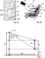
- Fig. 2 shows bounding boxes in an image 21 of a person in a vehicle cabin.
- the image 21 may be one of the images 11 of Fig. 1 .
- the image 21 may be a preprocessed to focus on the co-driver's seat or any other seat in the vehicle.
- the method can be applied to any seat, even to the driver's seat, e.g., if safety measures are associated with the height of a person sitting on a vehicle's seat.
- An algorithm to determine two bounding boxes may be applied, namely, one first bounding box 22 relating to the seat and one second bounding box 23 relating to the person's sitting height.
- the first bounding box 22 for the seat may be predefined as starting on the left upper corner with the seat belt outlet and ending on the right lower corner with the seat belt buckle.
- the coordinates of these anchor points may be predefined, e.g., stored in an on-board database, but may also be determined on the image 21. Since the real height of the vehicle backrest is known and the seat bounding box configuration with its anchor points is assumed to be correct and precise, the seat bounding box 22 of the seat serves as reference for determining the body characteristics.
- the heights A, B of both bounding boxes 22, 23 can then be extracted as a number of pixels and the height of the person can be determined.
- the real (base config) height of the seat may be known and denoted in the following as BH. Assume BH is 80 cm.
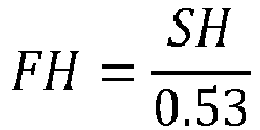
- the sitting height (SH) may be mapped to the full height (FH) or even to the age of a person.
- a filter can be added to smooth the result.
- FH SH 0.53
- SH 2.7 ⁇ age + 47
- a look-up table associating sitting heights with full heights and/or ages can be consulted to determine the height or the age of the person. Such look-up table will be discussed later with respect to Fig. 6 .
- the heights or ages may also be determined based on body key points, which is depicted in Figs. 3A and 3B.
- Fig. 3A depicts a person's skeleton based on body key points in an image 31, e.g., one of the images 11, of a person in a vehicle cabin.
- the image 31 may be a preprocessed to focus on only the co-driver's seat or any other seat in the vehicle.
- the method can be applied to any seat, even to the driver's seat, e.g., if safety measures are associated with the height of a person sitting on a vehicle's seat.
- a key point detector may detect key points for shoulders, hips, elbows, wrists, knees, and the like, of passengers in the vehicle. These body key points may be classified (e.g., as shoulder right key point, hip left key point etc.) and comprise the respective pixel values of a set of body key points. For example, the key point detector may detect both shoulder body key points and thereby the connecting line relating to the shoulder width 32 is formed. The process is the same for the hip width 33, the torso height 34, the upper arm length 35A, the lower arm length 35B, and the upper leg length 36A. More body key points can be detected so that the method may also determine a lower leg length or the like.
- Fig. 3B illustrates a camera view on the person's key points and possible joints formed by the person's body key points.
- camera 37 is located above the passenger and has only a limited view 38 on the passenger, who sits on the vehicle seat 39.
- the shoulder width 32, the hip width 33, the torso height 34, the upper arm length 35A, the lower arm length 35B, the upper leg length 36A and the lower leg length 36B of the passenger's joints are also shown although not all can be determined based on the image 31.
- the body key points provide the location of the joints in pixel coordinates. These coordinates can in turn be used to calculate the length of different body parts in units of pixels, e.g., torso height 34 (TH), shoulder width 32 (SW), hip width 33 (HW), and the like. When a length of a body part in units of pixels is known, the possible full height in centimeters (cm) can be determined.
- TH torso height 34
- SW shoulder width 32
- HW hip width 33
- a measured torso height 34 being 100 pixels. It may have been determined before that persons with 100 pixels torso height on the image 31 may have a full height in the range of [85, 90, 110, 125] cm. If additionally, the hip width 33 is measured to be 50 pixels, which correspond the full height range [80, 90, 105, 108] cm, and the shoulder width 32 is measured to have 75 pixels, which correspond to the full height range of [90, 120, 130] cm, the predicted height would be 90 cm as all three ranges comprise this height.
- the ranges may be determined for a particular vehicle based on the geometry, the person's position, the camera position, the possible movement of the seat (back, forth, up, and down), cabin dimensions, and the like. This enables to back project what could be the smallest and largest length of different body parts on units of pixels as captured by the camera. In that manner, a table may be formed, such as the table that is later discussed with respect to Fig. 6 .
- Fig. 4 is an example of back projection into the camera plane for determining a unit to pixel relation with respect to a torso height (TH) 34 a person.
- the camera 36 at point A is located at a camera height (CH) measured from a base line of the vehicle in cm.
- the seat is located at a seat distance (SD) measured from the horizontal reference point B of the camera 36 in cm and in a seat height (HH) measured from the base line of the vehicle in cm.
- Point C is the shoulder point of the person.
- Hip point D is assumed to be associated with the seat height.
- Points E and F are the horizontal reference points to points C and D.
- the minimum and maximum horizontal distances (SD) and the minimum and maximum seat height (HH) can be plugged-in in the above equations.
- This provides a limit of TH in units of pixels for a given TH in units of cm.
- a table for TH e.g., the one discussed later with respect to Fig. 6 , with minimum and maximum pixels values can be constructed.
- Fig. 5 is an example of back projection into the camera plane for determining a unit to pixel relation with respect to a shoulder width (SW) 32 of a person.
- the camera 36 at point A is located at a horizontal distance to the shoulder (DS) measured from a base line of the vehicle in cm.
- the seat is located at a seat distance (SD) measured from the horizontal reference point A of the camera 36 in cm and in a seat height (HH) measured from the base line of the vehicle in cm.
- Shoulder points C and D are set as such point D is assumed to be at the distance DS (e.g., according to a seat position) to the camera.
- Points E and F are the vertical reference points to points C and D.
- HW hip width
- upper arm length upper arm length
- upper leg length and the like. This results in multiple body part length ranges in pixels for one full height, which may be stored in one or multiple look-up tables.
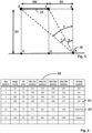
- Fig. 6 illustrates a possible look-up table 60 according to the disclosure.
- the table 60 comprises as columns 'Age', 'Height', 'SH', 'Min TH', 'Max TH', 'Min SW, 'Max SW and 'Airbag control'. More columns are possible, too, e.g., for other safety measures or other measured body parts.
- the age is given in number of years and the full body height ('Height') as well as the sitting height ('SH') are given in cm.
- the columns for the minimum and maximum torso heights ('TH'), shoulder widths ('SW'), and the like, list values in number of pixels.
- the final column 'Airbag control' indicates whether and how the airbag is deployed.
- such a look-up table may also only comprise a 'Height' column and an 'SH' column for a sitting height, or only a 'Height' column and a 'Min TH' and 'Max TH' column for a minimum and maximum torso height.
- the column 'Age' may be present or not depending on whether the control signal shall be based (also) on an age of the person.
- the look-up table 60 of Fig. 6 may have been determined as described before or pre-defined for the vehicle and camera model.
- the column 'Airbag' may indicate whether and how the airbag is deployed. For example, if a sitting height of 62 cm is determined but no other body parts, then, the height of the person is determined to be approximately 109 cm. Additionally, it may also be determined that the person is approximately 5 years old, which results in no deployment of the airbag for this passenger (see line 61 of table 60).
- the TH is 350 pixels and the SW is 220 pixels but no sitting height may be determined.
- the resulting estimated height is then 139 cm corresponding to an age of 10 years.
- the airbag would be deployed with reduced pressure as is shown in line 62 of table 60.
- determined body characteristics may differ from image to image, may lay in between two ranges, and the determination may be uncertain. For example, if a TH is determined to be 260 pixels and a SW is determined to be 192 pixels, which height is more likely, 95 or 103? Therefore, it may be advantageous to generate histograms over the one or more images 11 to get a more reliable vote for one height or age.
- Fig. 7 presents such an evolvement of histograms for determining the height of a passenger. Possible heights that correspond to the measured body characteristics are accumulated over multiple image frames and the peak in the histogram is used as final determined height. It is noted that a similar histogram for ages can be made as well. In such a histogram, possible ages of all features are then accumulated in an age histogram and the peak in that histogram is used as final estimated age. The histogram (irrespective of whether it relates to height or age) grows over time or multiple frames to get a robust estimate even if the person is temporarily out of position and some body characteristics cannot be determined well.
- the histograms of Fig. 7 show a histogram of one frame 71 and a histogram of 5 frames.
- the SW in pixels could belong to any of the heights [87, 95, 103]
- the TW in pixels could belong to any of the heights [109, 115, 122]
- the HW could belong to any of the heights [95, 103, 109].
- it is still uncertain which height the person has as three heights, namely, 95, 103, and 109 have the same number of votes.
- the histogram 72 the determined body characteristics of five frames show a better estimation. Now, the most likely height is 103 cm, which can be more reliably chosen and determined.
- Fig. 8 shows an example of modules implemented in a system for controlling one or more vehicle safety measures according to embodiments of the disclosure.
- An object detector 81 may provide bounding boxes for a seat and a person in a car.
- the seat base config may be retrieved, e.g., the real height of the seat backrest. Based on the two bounding boxes the sitting height of the passenger may be determined.
- a look-up table 812 may be consulted to determine the height 814 of the passenger according to the first path.
- a body key point module 82 may provide body key points for a person in a car.
- a look-up table 822 may be consulted to determine a possible height of the passenger.
- Look-up tables 812 and 822 may be the same look-up table or different look-up tables.
- a histogram 823 e.g., similar to that discussed with respect to Fig. 7 , may help to determine the height 824 of the passenger according to the second path.
- a histogram for determining the height according to the first path may also be used in a similar manner.
- Both results i.e., the heights 814 and 824 may be averaged in module 83.
- the system will determine the height separately and only afterwards average the two determinations.
- the system will take one height estimation and output as the final result.
- a weight parameter may be imported for averaging giving one estimation more weight.
- module 83 may also fuse the two histograms to determine a final result 84.
- Vehicle safety measures may comprise airbag deployment, seat belt control, and/or door locks.
- a control signal may lead to an airbag being deployed normally, with reduced pressure or deactivated.
- a control signal may also or alternatively lead to a seat belt being deployed normally or with softened force.
- a control signal may also or alternatively lead to a door being locked.
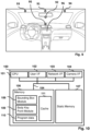
- Fig. 9 presents an interior of a vehicle with possible positions of cameras and a main display that may be used for capturing one or more images used for controlling one or more vehicle safety measures according to embodiments described herein.
- the vehicle may only comprise one camera but also a plurality of cameras at different positions.
- the cameras which may be color or black/which cameras, infrared cameras, depth cameras, heat cameras, or a combination thereof, can be placed, e.g., in the middle over the front windshield and even over the rearview mirror as illustrated with position 91. Additionally or alternatively, the or another camera can be located below the rearview mirror as illustrated with position 92. If one camera is located at position 93, another one will usually also be located at position 94 but this is not mandatory. With two cameras a depth image or 3D image may be created. Additionally or alternatively, the or another camera can be located the dashboard or in the middle console as depicted with position 95. Each of the positions 91 to 95 may also comprise two cameras co-located for enabling a 3D view of the interior of the vehicle.
- Cameras may capture images, e.g., at regular time intervals or if trigged by an application that requires to determine a passenger's height or age as described herein.
- the applications using the images may be executed on the onboard computing system or at least in part executed remotely, e.g., in the cloud.
- the result of the application may not only output a control signal to a safety measure but also trigger a display on a vehicle's main display 96 at the middle console.
- the vehicle's main display may also be located in another position, e.g., at the dashboard behind the steering wheel.
- Fig. 10 is a diagrammatic representation of internal components of a computing system 100 implementing the functionality as described herein.
- the computing system 100 may be located in the vehicle and includes at least one processor 101, a user interface 102, a network interface 103 and a main memory 106, that communicate with each other via a bus 105.
- the computing system 100 may further include a static memory 107 and a disk-drive unit (not shown) that also communicate with each via the bus 105.
- a video display, an alpha-numeric input device and a cursor control device may be provided as examples of user interface 102.
- the computing system 100 may also comprise a specified camera interface 104 to communicate with an onboard camera of the vehicle.
- the computing system 100 may communicate with the camera via the network interface 103.
- the camera is used for taking the image.
- the computing system 100 may also be connected to database systems (not shown) via the network interface, wherein the database systems store at least part of the images needed for providing the functionalities described herein.
- the main memory 106 may be a random-access memory (RAM) and/or any further volatile memory.
- the main memory 106 may store program code for a bounding box module 108 and for a body key point module 109, which implement the methods described herein. Other modules needed for further functionalities described herein may be stored in the memory 106.
- the memory 106 may also store additional program data 110 required for providing the functionalities described herein. Part of the program data 110, the bounding box module 108 and/or for the body key point module 109 may also be stored in a separate, e.g., cloud memory and executed at least in part remotely.
- the memory 106 may store data about the determined child seat model type saccording to the methods describes herein in a cache 111.
- a vehicle is provided.
- the herein described methods may be stored as program codes 108, 109, or 110 and may be at least in part comprised by the vehicle. Parts of the program codes 108, 109, or 110 may also be stored and executed on a cloud server to reduce the computational effort on the vehicle's computing system 100.
- the vehicle may also comprise one or more cameras, e.g., connected via the camera interface 104, for capturing one or more images.
- a computer program comprising instructions. These instructions, when the program is executed by a computer, cause the computer to carry out the methods described herein.
- the program code embodied in any of the systems described herein is capable of being individually or collectively distributed as a program product in a variety of different forms.
- the program code may be distributed using a computer readable storage medium having computer readable program instructions thereon for causing a processor to carry out aspects of the embodiments described herein.
- Computer readable storage media which are inherently non-transitory, may include volatile and non-volatile, and removable and non-removable tangible media implemented in any method or technology for storage of information, such as computer-readable instructions, data structures, program modules, or other data.
- Computer readable storage media may further include random access memory (RAM), read-only memory (ROM), erasable programmable read-only memory (EPROM), electrically erasable programmable read-only memory (EEPROM), flash memory or other solid state memory technology, portable compact disc read-only memory (CD-ROM), or other optical storage, magnetic cassettes, magnetic tape, magnetic disk storage or other magnetic storage devices, or any other medium that can be used to store the desired information and which can be read by a computer.
- RAM random access memory
- ROM read-only memory
- EPROM erasable programmable read-only memory
- EEPROM electrically erasable programmable read-only memory
- CD-ROM portable compact disc read-only memory
- magnetic cassettes magnetic tape
- magnetic disk storage
- a computer readable storage medium should not be construed as transitory signals per se (e.g., radio waves or other propagating electromagnetic waves, electromagnetic waves propagating through a transmission media such as a waveguide, or electrical signals transmitted through a wire).
- Computer readable program instructions may be downloaded to a computer, another type of programmable data processing apparatus, or another device from a computer readable storage medium or to an external computer or external storage device via a network.
- any of the flowcharts, sequence diagrams, and/or block diagrams may include more or fewer blocks than those illustrated consistent with embodiments of the disclosure.
Landscapes
- Engineering & Computer Science (AREA)
- Theoretical Computer Science (AREA)
- Physics & Mathematics (AREA)
- General Physics & Mathematics (AREA)
- Computer Vision & Pattern Recognition (AREA)
- Multimedia (AREA)
- Data Mining & Analysis (AREA)
- Artificial Intelligence (AREA)
- Evolutionary Computation (AREA)
- Mechanical Engineering (AREA)
- Human Computer Interaction (AREA)
- Geometry (AREA)
- Software Systems (AREA)
- Medical Informatics (AREA)
- General Health & Medical Sciences (AREA)
- Databases & Information Systems (AREA)
- Computing Systems (AREA)
- Health & Medical Sciences (AREA)
- Life Sciences & Earth Sciences (AREA)
- Bioinformatics & Cheminformatics (AREA)
- Bioinformatics & Computational Biology (AREA)
- Evolutionary Biology (AREA)
- General Engineering & Computer Science (AREA)
- Air Bags (AREA)
Abstract
A computerized method of controlling one or more vehicle safety measures by determining the height of a person sitting on a seat in a vehicle cabin is provided. The method comprises determining, based on one or more images showing the person on a vehicle seat, a height of the person by determining a set of body characteristics of the person, comparing the set of determined body characteristics with a corresponding set of reference characteristics, and determining the height of the person based on the comparison. The method further comprises outputting a control signal to the one or more vehicle safety measures based at least partially on the determined height.
Description
- The present disclosure generally relates to safety improvements for vehicles and, in particular, to methods and systems of controlling vehicle safety measures by determining the height of a person in a vehicle.
- Smart vehicles, such as smart cars, smart busses, and the like, are on their way to significantly improve the safety of passengers. Such smart vehicles may be equipped with onboard cameras and may be capable of capturing images of the vehicle's interior. Those images can then be used, sometimes in combination with other sensors, for different safety related tasks.
- Safety tasks in a vehicle relate to controlling safety measures, such as airbag or seatbelt deployment, door or windows locks and the like. In modern smart cars, these safety measures can be based on person detection and classification. Person detection and classification therefore plays an important role in future vehicles, for example, in seat occupancy detection. Seat occupancy detection is applied to determine whether or not a person is located on a seat. However, such a basic detection whether or not a person is located on a seat is not enough for reliably controlling all safety measures in a reliable way.
- Hence, there is a need for an improved system for controlling of safety measures.
- In this context, methods, systems and computer program products are presented as defined by the independent claims.
- More specifically, a computerized method of controlling one or more vehicle safety measures by determining the height of a person sitting on a seat in a vehicle cabin is provided. The method comprises determining, based on one or more images showing the person on a vehicle seat, a height of the person by determining a set of body characteristics of the person, comparing the set of determined body characteristics with a corresponding set of reference characteristics, and determining the height of the person based on the comparison. The method further comprises outputting a control signal to the one or more vehicle safety measures based at least partially on the determined height.
- In embodiments, the set of reference characteristics are stored in a database, wherein the database may be a local database of the vehicle or a remote database to the vehicle. In some embodiments, the one or more vehicle safety measures comprise airbag deployment, seat belt control, and/or door locks.
- In embodiments, determining the set of body characteristics is based on bounding boxes and comprises determining, based on the one or more images, a first bounding box for the seat, and determining, based on the one or more images, a second bounding box for the person. In further embodiments, the set of body characteristics comprises a sitting height of the person, wherein the sitting height is determined based a difference between a height of the first bounding box and a height of the second bounding box. In yet further embodiments, the difference is determined as number of pixels in the one or more images, wherein determining the set of body characteristics further comprises converting the number of pixels to a metric unit according to the height of the first bounding box.
- In embodiments, determining the set of body characteristics is based on body key points and comprises determining, based on the one or more images, a plurality of body key points. In further embodiments, the set of body characteristics comprises at least one length of a body part, wherein the length of a body part is determined based on a difference between a pixel coordinate of a first body key point and a pixel coordinate of a second body key point. In yet further embodiment, the at least one length of a body part comprises at least one of a torso height, a shoulder width, a hip width, an upper arm length, a lower arm length, and a leg length.
- In embodiments, reference characteristics in the set of reference characteristics are associated with ages of persons. In further embodiment, the method further comprises determining, based on the one or more images, a probability histogram according to the determined set of body characteristics.
- In embodiments, determination of the set of body characteristics is based on bounding boxes and body key points and the method further comprises determining a first height of the person based on bounding boxes, determining a second height based on body key points, and fusing the first height and the second height to determine the height of the person.
- Another aspect concerns a system of controlling one or more vehicle safety measures, the system implementing the methods as described herein.
- A further aspect concerns a vehicle comprising a camera for capturing one or more images, and the system for controlling one or more vehicle safety measures as described herein.
- A final aspect concerns a computer program product comprising instructions, which, when executed on a computer, cause the computer to perform the methods as described herein.
- These and other objects, embodiments and advantages will become readily apparent to those skilled in the art from the following detailed description of the embodiments having reference to the attached figures, the disclosure not being limited to any particular embodiments.
- The foregoing and further objects, features and advantages of the present subject matter will become apparent from the following description of exemplary embodiments with reference to the accompanying drawings, wherein like numerals are used to represent like elements, in which:
-
Fig. 1 is a high-level flow-chart of a method for controlling one or more vehicle safety measures according to the disclosure. -
Fig. 2 shows bounding boxes in an image of a person in a vehicle cabin. -
Fig. 3A depicts a person's skeleton based on body key points in an image of a person in a vehicle cabin.Fig. 3B illustrates a camera view on the person's key points and possible joints formed by the person's body key points. -
Fig. 4 is an example of back projection into the camera plane for determining a unit to pixel relation with respect to a torso height a person. -
Fig. 5 is an example of back projection into the camera plane for determining a unit to pixel relation with respect to a shoulder width of a person. -
Fig. 6 illustrates a possible look-up table according to the disclosure. -
Fig. 7 presents an evolvement of histograms for determining the height of a passenger. -
Fig. 8 shows an example of modules implemented in a system for controlling one or more vehicle safety measures according to embodiments of the disclosure. -
Fig. 9 presents an interior of a vehicle with possible positions of cameras. -
Fig. 10 is diagrammatic representation of a computing system implementing the functionalities described herein. - The present disclosure relates to methods and systems for controlling vehicle safety measures by determining the height of a person. Detection of persons in a vehicle already plays an important role for ensuring safety. However, it may be often not enough to only detect whether a person in sitting in a vehicle, but further information relating to the person may be of relevance for safety and control function of the vehicle, too.
- For example, the age of a detected person may be relevant to distinguish a child from an adult. If a child up to a specific age is detected, airbag deployment may be controlled such that the airbag is completely suppressed to protect the child. For older children, the airbag deployment may be controlled such that the airbag is allowed to inflate but only with a reduced pressure. Other examples of safety measures that may be deployed differently depending on the height and/or age of a person are, e.g., seatbelts, door locks, and the like. Safety measure control may also be a regulatory requirement by law, e.g., US regulation FMVSS208. Hence, it may be required to reliably differentiate children from adults (e.g., by age and/or by height), in order to be compliant with regulatory requirements.
- This disclosure presents a solution for safety measure control based on existing information available in a vehicle, which allows an estimation of the height of the passengers sitting in a vehicle, for which a high-level flow-chart is presented in
Fig. 1 . - The method of controlling one or more vehicle safety measures by determining the height of a person sitting on a seat in a vehicle cabin presented in
Fig. 1 is based on one ormore images 11. The one ormore images 11 show the person sitting on a vehicle seat. Theimages 11 may be taken by one or more on-board cameras of the vehicle. - Modern vehicles, in particular, cars, can be equipped with one or more cameras. These cameras, which may comprise one or more of color or black/which cameras, infrared cameras, depth cameras, and heat cameras, provide
images 11 of the vehicle's interior to internal components of the vehicle. Theimages 11 may be taken in response to a triggering event, e.g., opening a door, interacting with a multi-media system of the vehicle, using a voice command, or the like, or at defined periodic or non-periodic time intervals. Theimages 11 taken may then be used by a plurality of internal systems for controlling safety means as herein described but also for entertainment and comfort use cases. -
Images 11 of the vehicle's interior may comprise full images showing the whole interior. Alternatively, theimages 11 may depict only a partly region of the interior, e.g., one front seat, one or more rear seats, a door region, and such. If a camera captures the whole interior, theimages 11 may be preprocessed image crops that have been extracted from one or more raw images for one or more regions in the vehicle. - Based on the
images 11, a height of the person on theimages 11 is determined inbox 12. Finally, based at least partially on the determined height of the person, a control signal is output to one or more vehicle safety measures, which is shown inbox 13. Vehicle safety measures may comprise airbag deployment, seat belt control, and/or door locks. A control signal may lead to an airbag being deployed normally, with reduced pressure or deactivated. A control signal may also or alternatively lead to a seat belt being deployed normally or with softened force. A control signal may also or alternatively lead to a door being locked. - The height of the person may not directly be determined from the
images 11 as only parts of the person are typically present in theimages 11. For example, the lower legs will not be detectable on theimages 11 when the person is sitting. Moreover, other body parts may be obstructed by the vehicle's interior components, too. Hence, the method presents herein does not directly determine the height of the person but starts with determining a set of body characteristics of the person in box 12-1. - Such body characteristics may be a sitting height, e.g., the distance between the hips to the apex of the head, a torso height, e.g., the distance between the hips and the shoulders, a shoulder width, e.g., the distance between the right shoulder joint and the left shoulder joint, a hip width, e.g., the distance between the right hip joint and the left hip joint, an upper arm length, a lower arm length, an upper leg length, a lower leg length, and the like.
- In some embodiments, the body characteristics may be determined based on bounding boxes determined on the
images 11. For example, a first bounding box may be generated for the seat and a second bounding box may be generated for the person. Bounding boxes may be generated by an object detection algorithm. The object detection algorithm may be a machine learning algorithm trained on example images. The machine learning algorithm may be based on a machine learning method like a gradient boosted tree, a random forest, an artificial neural network, a recurrent neural network, a convolutional neural network, an autoencoder, a deep learning architecture, a support vector machine, a data-driven trainable regression model, a k-nearest-neighbor classifier, a physical model, and/or a decision tree, or a combination thereof. The machine learning algorithm for generating the bounding boxes may be trained remotely before use of the vehicle and applied during use of the vehicle. The machine learning algorithm may also be retrained during use of the vehicle. Use of the vehicle is to be understood as anything that activates the power supply in the vehicle, i.e., unlocking the doors, approaching the vehicle with the key/token for keyless entry systems, driving the vehicle, and the like. - In some examples, the bounding box for the seat may be predefined as starting on the left upper corner with the seat belt outlet and ending on the right lower corner with the seat belt buckle. The coordinates of these anchor points may be predefined, e.g., stored in an on-board database, but may also be determined on the
images 11. Since the real height of the vehicle backrest is known and the seat bounding box configuration with its anchor points is assumed to be correct and precise, the seat bounding box of the seat serves as reference for determining the body characteristics. - In examples, in which the set of characteristics is determined based on bounding boxes, the set of body characteristics may comprise a sitting height of the person. The sitting height of the person may then be determined based on a difference between a height of the first bounding box relating to the seat and a height of the second bounding box relating to the person. In such examples, the difference between the bounding boxes may be determined as a number of pixels in the one or
more images 11 of the vehicle's interior. The number of pixels may then be converted to a metric unit according to the height of the first bounding box. This is possible since the real height of the backrest of the seat, which corresponds to the height of the first bounding box, is known as explained above. - Additionally or alternatively, the set of body characteristics may be determined based on body key points. In such example, a plurality of body key points of the person is determined based on the one or
more images 11. In such an example, the length of a body part may be determined based on a difference between a pixel coordinate of a first body key point and a pixel coordinate of a second body key point. The set of body characteristics may then comprise at least one length of a body part, e.g., a torso height, a shoulder width, a hip width, an upper arm length, a lower arm length, an upper leg length, a lower leg length, and the like. - The body key points may be provided by a key point detector, which may be based on machine learning techniques and which is applied on the one or
more images 11. The key point detector may detect several body key points for a passenger. For example, the key point detector may detect key points for shoulders, hips, elbows, wrists, knees, and the like, of passengers in the vehicle. These body key points may be classified and comprise the respective pixel values of a set of body key points for a passenger. - When the set of body characteristics has been determined, this is compared with a corresponding set of reference characteristics in box 12-2. The set of reference characteristics may be stored in an on-board memory of the vehicle or retrieved from a remote cloud database. Based on the comparison, the height of the person may be determined as shown in box 12-3. In some examples, determining a probability histogram relating to a height estimation according to the determined set of body characteristics and the set of reference characteristics for determining the height of the person may be beneficial. The probability histogram may also evolve over multiple time frames and
images 11. - For example, a set of reference characteristics may be a function or a table associating ranges of sitting heights with total body heights of persons. Hence, a determined sitting height may be compared with the result of the function or the table and a resulting height of the passenger may be determined based on the comparison. In another example, the set of reference characteristics may refer to a plurality of tables or datasets that associate a plurality of body characteristics, such as the sitting height, the torso height, the shoulder width, the hip width, the upper arm length, the lower arm length, the upper leg length, the lower leg length etc. with heights of persons.
- In some examples, the set of reference characteristics may also be associated with ages of persons. In such examples, the method may not only determine a height of a person but also a likely age of the person, which may also be relevant to the outputting of the control signal. Since the heights of persons of a specific age (up to the age when being grown up, e.g., 16, 18 or 20) may vary a lot, it may be specifically advantageous in such cases to determine a probability histogram relating to age estimation according to the determined set of body characteristics and the set of reference characteristics.
- In some embodiments, the determination of the set of body characteristics may be based on bounding boxes and body key points, i.e., both approaches may be implemented in one system. In such examples, the method may further comprise determining a first height of the person based on bounding boxes and determining a second height based on body key points. If both height estimations are available, the method may further comprise fusing the first height and the second height to determine the height of the person. Fusing may comprise averaging the first and second heights to for the finally determined height of the person, prioritizing the first or the second height over the other, forming a weighting average or the like. Additionally or alternatively, if one of the two height estimations is not available, e.g., because an image does not show enough details for one or the other method, the height may be determined on the remaining one, e.g., only based on bounding boxes,
-
Fig. 2 shows bounding boxes in animage 21 of a person in a vehicle cabin. Theimage 21 may be one of theimages 11 ofFig. 1 . Theimage 21 may be a preprocessed to focus on the co-driver's seat or any other seat in the vehicle. As will be apparent to the skilled person, the method can be applied to any seat, even to the driver's seat, e.g., if safety measures are associated with the height of a person sitting on a vehicle's seat. An algorithm to determine two bounding boxes may be applied, namely, onefirst bounding box 22 relating to the seat and onesecond bounding box 23 relating to the person's sitting height. - In some examples, the
first bounding box 22 for the seat may be predefined as starting on the left upper corner with the seat belt outlet and ending on the right lower corner with the seat belt buckle. The coordinates of these anchor points may be predefined, e.g., stored in an on-board database, but may also be determined on theimage 21. Since the real height of the vehicle backrest is known and the seat bounding box configuration with its anchor points is assumed to be correct and precise, theseat bounding box 22 of the seat serves as reference for determining the body characteristics. - The heights A, B of both bounding
boxes 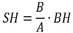
- With a growth chart look-up-table or a tuned function, the sitting height (SH) may be mapped to the full height (FH) or even to the age of a person. In some embodiments, a filter can be added to smooth the result. The following exemplary functions may be applied for 2-17 years old persons:

- Alternatively, a look-up table associating sitting heights with full heights and/or ages can be consulted to determine the height or the age of the person. Such look-up table will be discussed later with respect to
Fig. 6 . - In addition or alternatively to the determination of heights or ages of persons based on bounding boxes, the heights or ages may also be determined based on body key points, which is depicted in
Figs. 3A and 3B. Fig. 3A depicts a person's skeleton based on body key points in animage 31, e.g., one of theimages 11, of a person in a vehicle cabin. Theimage 31 may be a preprocessed to focus on only the co-driver's seat or any other seat in the vehicle. As will be apparent to the skilled person, the method can be applied to any seat, even to the driver's seat, e.g., if safety measures are associated with the height of a person sitting on a vehicle's seat. - A key point detector may detect key points for shoulders, hips, elbows, wrists, knees, and the like, of passengers in the vehicle. These body key points may be classified (e.g., as shoulder right key point, hip left key point etc.) and comprise the respective pixel values of a set of body key points. For example, the key point detector may detect both shoulder body key points and thereby the connecting line relating to the
shoulder width 32 is formed. The process is the same for thehip width 33, thetorso height 34, theupper arm length 35A, thelower arm length 35B, and theupper leg length 36A. More body key points can be detected so that the method may also determine a lower leg length or the like. -
Fig. 3B illustrates a camera view on the person's key points and possible joints formed by the person's body key points. As can be seen in this example,camera 37 is located above the passenger and has only alimited view 38 on the passenger, who sits on thevehicle seat 39. Theshoulder width 32, thehip width 33, thetorso height 34, theupper arm length 35A, thelower arm length 35B, theupper leg length 36A and thelower leg length 36B of the passenger's joints are also shown although not all can be determined based on theimage 31. - The body key points provide the location of the joints in pixel coordinates. These coordinates can in turn be used to calculate the length of different body parts in units of pixels, e.g., torso height 34 (TH), shoulder width 32 (SW), hip width 33 (HW), and the like. When a length of a body part in units of pixels is known, the possible full height in centimeters (cm) can be determined.
- For example, assume a measured
torso height 34 being 100 pixels. It may have been determined before that persons with 100 pixels torso height on theimage 31 may have a full height in the range of [85, 90, 110, 125] cm. If additionally, thehip width 33 is measured to be 50 pixels, which correspond the full height range [80, 90, 105, 108] cm, and theshoulder width 32 is measured to have 75 pixels, which correspond to the full height range of [90, 120, 130] cm, the predicted height would be 90 cm as all three ranges comprise this height. - The ranges may be determined for a particular vehicle based on the geometry, the person's position, the camera position, the possible movement of the seat (back, forth, up, and down), cabin dimensions, and the like. This enables to back project what could be the smallest and largest length of different body parts on units of pixels as captured by the camera. In that manner, a table may be formed, such as the table that is later discussed with respect to
Fig. 6 . -
Fig. 4 is an example of back projection into the camera plane for determining a unit to pixel relation with respect to a torso height (TH) 34 a person. Thecamera 36 at point A is located at a camera height (CH) measured from a base line of the vehicle in cm. The seat is located at a seat distance (SD) measured from the horizontal reference point B of thecamera 36 in cm and in a seat height (HH) measured from the base line of the vehicle in cm. Point C is the shoulder point of the person. Hip point D is assumed to be associated with the seat height. Points E and F are the horizontal reference points to points C and D. - The person is assumed to have a torso height of TH in cm. In order to back project this height into the camera, the angle c is determined, which is given as c = a - b. Consider the right-angled triangle formed by vertices A, D, and F. The formula for the angle b is:

- Similarly, consider the right-angled triangle formed by vertices A, C, and E. The formula for the angle a is:

- Then, the angle c can be determined as mentioned above by c = a - b. With the property 'pixel per degree' (PPD) of the
camera 36, the torso height can be determined in units of pixels as:
- To accommodate for the movement of the seat backwards, forwards, upwards and downwards, the minimum and maximum horizontal distances (SD) and the minimum and maximum seat height (HH) can be plugged-in in the above equations. This in turn provides a limit of TH in units of pixels for a given TH in units of cm. This way a table for TH, e.g., the one discussed later with respect to
Fig. 6 , with minimum and maximum pixels values can be constructed. -
Fig. 5 is an example of back projection into the camera plane for determining a unit to pixel relation with respect to a shoulder width (SW) 32 of a person. Thecamera 36 at point A is located at a horizontal distance to the shoulder (DS) measured from a base line of the vehicle in cm. The seat is located at a seat distance (SD) measured from the horizontal reference point A of thecamera 36 in cm and in a seat height (HH) measured from the base line of the vehicle in cm. Shoulder points C and D are set as such point D is assumed to be at the distance DS (e.g., according to a seat position) to the camera. Points E and F are the vertical reference points to points C and D. - The person is assumed to have a shoulder width of SW in cm. In order to back project this width into the camera, the angle c is determined, which is given as c = a - b. Consider the right-angled triangle formed by vertices A, B, and C. The formula for the angle b is:

- Similarly, consider the right-angled triangle formed by vertices A, B, and D. The formula for the angle a is:

- Then, the angle c can be determined as mentioned above by c = a - b. With the property 'pixel per degree' (PPD) of the
camera 36, the shoulder width can be determined in units of pixels as:
- In other examples, a rotation angle d of the shoulder can be considered, too. Then, formula b may be changed to:

- A variation of the horizontal distance D (due to movement of seat back and forth) and, in some examples, of the rotation of shoulder by angle d, e.g., 0-5 degrees, gives minimum and maximum values for SW in units of pixels which constructs the look-up table for shoulder width, such as shown in the following
Fig. 6 . - Similar geometries and mathematical calculations as above can be used for back projection of other body parts such as hip width (HW), upper arm length, upper leg length, and the like. This results in multiple body part length ranges in pixels for one full height, which may be stored in one or multiple look-up tables.
-
Fig. 6 illustrates a possible look-up table 60 according to the disclosure. The table 60 comprises as columns 'Age', 'Height', 'SH', 'Min TH', 'Max TH', 'Min SW, 'Max SW and 'Airbag control'. More columns are possible, too, e.g., for other safety measures or other measured body parts. In the example, the age is given in number of years and the full body height ('Height') as well as the sitting height ('SH') are given in cm. The columns for the minimum and maximum torso heights ('TH'), shoulder widths ('SW'), and the like, list values in number of pixels. The final column 'Airbag control' indicates whether and how the airbag is deployed. - In the simplest form, such a look-up table may also only comprise a 'Height' column and an 'SH' column for a sitting height, or only a 'Height' column and a 'Min TH' and 'Max TH' column for a minimum and maximum torso height. The column 'Age' may be present or not depending on whether the control signal shall be based (also) on an age of the person.
- The look-up table 60 of
Fig. 6 may have been determined as described before or pre-defined for the vehicle and camera model. The column 'Airbag' may indicate whether and how the airbag is deployed. For example, if a sitting height of 62 cm is determined but no other body parts, then, the height of the person is determined to be approximately 109 cm. Additionally, it may also be determined that the person is approximately 5 years old, which results in no deployment of the airbag for this passenger (seeline 61 of table 60). - In another example, it may be determined that the TH is 350 pixels and the SW is 220 pixels but no sitting height may be determined. The resulting estimated height is then 139 cm corresponding to an age of 10 years. In this example, the airbag would be deployed with reduced pressure as is shown in
line 62 of table 60. However, determined body characteristics may differ from image to image, may lay in between two ranges, and the determination may be uncertain. For example, if a TH is determined to be 260 pixels and a SW is determined to be 192 pixels, which height is more likely, 95 or 103? Therefore, it may be advantageous to generate histograms over the one ormore images 11 to get a more reliable vote for one height or age. -
Fig. 7 presents such an evolvement of histograms for determining the height of a passenger. Possible heights that correspond to the measured body characteristics are accumulated over multiple image frames and the peak in the histogram is used as final determined height. It is noted that a similar histogram for ages can be made as well. In such a histogram, possible ages of all features are then accumulated in an age histogram and the peak in that histogram is used as final estimated age. The histogram (irrespective of whether it relates to height or age) grows over time or multiple frames to get a robust estimate even if the person is temporarily out of position and some body characteristics cannot be determined well. - The histograms of
Fig. 7 show a histogram of oneframe 71 and a histogram of 5 frames. In thehistogram 71, it may be assumed that the SW in pixels could belong to any of the heights [87, 95, 103], the TW in pixels could belong to any of the heights [109, 115, 122], and the HW could belong to any of the heights [95, 103, 109]. In this example, it is still uncertain, which height the person has as three heights, namely, 95, 103, and 109 have the same number of votes. In thehistogram 72, the determined body characteristics of five frames show a better estimation. Now, the most likely height is 103 cm, which can be more reliably chosen and determined. -
Fig. 8 shows an example of modules implemented in a system for controlling one or more vehicle safety measures according to embodiments of the disclosure. Anobject detector 81 may provide bounding boxes for a seat and a person in a car. In 811, the seat base config may be retrieved, e.g., the real height of the seat backrest. Based on the two bounding boxes the sitting height of the passenger may be determined. A look-up table 812 may be consulted to determine theheight 814 of the passenger according to the first path. - A body
key point module 82 may provide body key points for a person in a car. A look-up table 822 may be consulted to determine a possible height of the passenger. Look-up tables 812 and 822 may be the same look-up table or different look-up tables. In some embodiments, ahistogram 823, e.g., similar to that discussed with respect toFig. 7 , may help to determine theheight 824 of the passenger according to the second path. Although not shown inFig. 8 , a histogram for determining the height according to the first path may also be used in a similar manner. - Both results, i.e., the
heights module 83. In other words, if the information of object detection and body key points is both available, the system will determine the height separately and only afterwards average the two determinations. Of course, if only one information is available, e.g. if the bodykey point module 82 does not provide enough information to let the system calculate the height, the system will take one height estimation and output as the final result. In addition, based on the statistical analysis of the accuracy of the two methods, a weight parameter may be imported for averaging giving one estimation more weight. Moreover, in some embodiments, if the height in the first path and in the second path is determined based on a histogram,module 83 may also fuse the two histograms to determine afinal result 84. - Finally, the
result 84, e.g., the final determined height, is used for outputting a control signal to a safety measure in the vehicle. Vehicle safety measures may comprise airbag deployment, seat belt control, and/or door locks. A control signal may lead to an airbag being deployed normally, with reduced pressure or deactivated. A control signal may also or alternatively lead to a seat belt being deployed normally or with softened force. A control signal may also or alternatively lead to a door being locked. -
Fig. 9 presents an interior of a vehicle with possible positions of cameras and a main display that may be used for capturing one or more images used for controlling one or more vehicle safety measures according to embodiments described herein. - The vehicle may only comprise one camera but also a plurality of cameras at different positions. The cameras, which may be color or black/which cameras, infrared cameras, depth cameras, heat cameras, or a combination thereof, can be placed, e.g., in the middle over the front windshield and even over the rearview mirror as illustrated with
position 91. Additionally or alternatively, the or another camera can be located below the rearview mirror as illustrated withposition 92. If one camera is located atposition 93, another one will usually also be located atposition 94 but this is not mandatory. With two cameras a depth image or 3D image may be created. Additionally or alternatively, the or another camera can be located the dashboard or in the middle console as depicted withposition 95. Each of thepositions 91 to 95 may also comprise two cameras co-located for enabling a 3D view of the interior of the vehicle. - Cameras may capture images, e.g., at regular time intervals or if trigged by an application that requires to determine a passenger's height or age as described herein. The applications using the images may be executed on the onboard computing system or at least in part executed remotely, e.g., in the cloud. The result of the application may not only output a control signal to a safety measure but also trigger a display on a vehicle's
main display 96 at the middle console. The vehicle's main display may also be located in another position, e.g., at the dashboard behind the steering wheel. -
Fig. 10 is a diagrammatic representation of internal components of acomputing system 100 implementing the functionality as described herein. Thecomputing system 100 may be located in the vehicle and includes at least oneprocessor 101, auser interface 102, anetwork interface 103 and amain memory 106, that communicate with each other via a bus 105. Optionally, thecomputing system 100 may further include astatic memory 107 and a disk-drive unit (not shown) that also communicate with each via the bus 105. A video display, an alpha-numeric input device and a cursor control device may be provided as examples ofuser interface 102. - Furthermore, the
computing system 100 may also comprise a specifiedcamera interface 104 to communicate with an onboard camera of the vehicle. Alternatively, thecomputing system 100 may communicate with the camera via thenetwork interface 103. The camera is used for taking the image. Thecomputing system 100 may also be connected to database systems (not shown) via the network interface, wherein the database systems store at least part of the images needed for providing the functionalities described herein. - The
main memory 106 may be a random-access memory (RAM) and/or any further volatile memory. Themain memory 106 may store program code for abounding box module 108 and for a bodykey point module 109, which implement the methods described herein. Other modules needed for further functionalities described herein may be stored in thememory 106. Thememory 106 may also storeadditional program data 110 required for providing the functionalities described herein. Part of theprogram data 110, thebounding box module 108 and/or for the bodykey point module 109 may also be stored in a separate, e.g., cloud memory and executed at least in part remotely. In an exemplary embodiment, thememory 106 may store data about the determined child seat model type saccording to the methods describes herein in acache 111. - According to an aspect, a vehicle is provided. The herein described methods may be stored as
program codes program codes computing system 100. The vehicle may also comprise one or more cameras, e.g., connected via thecamera interface 104, for capturing one or more images. - According to an aspect, a computer program comprising instructions is provided. These instructions, when the program is executed by a computer, cause the computer to carry out the methods described herein. The program code embodied in any of the systems described herein is capable of being individually or collectively distributed as a program product in a variety of different forms. In particular, the program code may be distributed using a computer readable storage medium having computer readable program instructions thereon for causing a processor to carry out aspects of the embodiments described herein.
- Computer readable storage media, which are inherently non-transitory, may include volatile and non-volatile, and removable and non-removable tangible media implemented in any method or technology for storage of information, such as computer-readable instructions, data structures, program modules, or other data. Computer readable storage media may further include random access memory (RAM), read-only memory (ROM), erasable programmable read-only memory (EPROM), electrically erasable programmable read-only memory (EEPROM), flash memory or other solid state memory technology, portable compact disc read-only memory (CD-ROM), or other optical storage, magnetic cassettes, magnetic tape, magnetic disk storage or other magnetic storage devices, or any other medium that can be used to store the desired information and which can be read by a computer.
- A computer readable storage medium should not be construed as transitory signals per se (e.g., radio waves or other propagating electromagnetic waves, electromagnetic waves propagating through a transmission media such as a waveguide, or electrical signals transmitted through a wire). Computer readable program instructions may be downloaded to a computer, another type of programmable data processing apparatus, or another device from a computer readable storage medium or to an external computer or external storage device via a network.
- It should be appreciated that while particular embodiments and variations have been described herein, further modifications and alternatives will be apparent to persons skilled in the relevant arts. In particular, the examples are offered by way of illustrating the principles, and to provide a number of specific methods and arrangements for putting those principles into effect.
- In certain embodiments, the functions and/or acts specified in the flowcharts, sequence diagrams, and/or block diagrams may be re-ordered, processed serially, and/or processed concurrently without departing from the scope of the disclosure. Moreover, any of the flowcharts, sequence diagrams, and/or block diagrams may include more or fewer blocks than those illustrated consistent with embodiments of the disclosure.
- The terminology used herein is for the purpose of describing particular embodiments only and is not intended to be limiting of the embodiments of the disclosure. It will be further understood that the terms "comprise" and/or "comprising," when used in this specification, specify the presence of stated features, integers, steps, operations, elements, and/or components, but do not preclude the presence or addition of one or more other features, integers, steps, operations, elements, components, and/or groups thereof. Furthermore, to the extent that the terms "include", "having", "has", "with", "comprised of", or variants thereof are used in either the detailed description or the claims, such terms are intended to be inclusive in a manner similar to the term "comprising".
- While a description of various embodiments has illustrated the method and while these embodiments have been described in considerable detail, it is not the intention of the applicants to restrict or in any way limit the scope of the appended claims to such detail. Additional advantages and modifications will readily appear to those skilled in the art. The disclosure in its broader aspects is therefore not limited to the specific details, representative apparatus and method, and illustrative examples shown and described. Accordingly, the described embodiments should be understood as being provided by way of example, for the purpose of teaching the general features and principles, but should not be understood as limiting the scope, which is as defined in the appended claims.
Claims (15)
- A computerized method of controlling one or more vehicle safety measures by determining the height of a person sitting on a seat in a vehicle cabin, comprising:- determining, based on one or more images showing the person on a vehicle seat, a height of the person by:▪ determining a set of body characteristics of the person;▪ comparing the set of determined body characteristics with a corresponding set of reference characteristics; and▪ determining the height of the person based on the comparison; and- outputting a control signal to the one or more vehicle safety measures based at least partially on the determined height.
- The method according to claim 1, wherein the set of reference characteristics are stored in a database, wherein the database may be a local database of the vehicle or a remote database to the vehicle.
- The method according to any one of the preceding claims, wherein the one or more vehicle safety measures comprise airbag deployment, seat belt control, and/or door locks.
- The method according to any of the preceding claims, wherein determining the set of body characteristics is based on bounding boxes and comprises:- determining, based on the one or more images, a first bounding box for the seat; and- determining, based on the one or more images, a second bounding box for the person.
- The method according to claim 4, wherein the set of body characteristics comprises a sitting height of the person, wherein the sitting height is determined based a difference between a height of the first bounding box and a height of the second bounding box.
- The method according to claim 5, wherein the difference is determined as number of pixels in the one or more images, wherein determining the set of body characteristics further comprises converting the number of pixels to a metric unit according to the height of the first bounding box.
- The method according to any one of the preceding claims, wherein determining the set of body characteristics is based on body key points and comprises determining, based on the one or more images, a plurality of body key points.
- The method according to claim 7, wherein the set of body characteristics comprises at least one length of a body part, wherein the length of a body part is determined based on a difference between a pixel coordinate of a first body key point and a pixel coordinate of a second body key point.
- The method according to claim 8, wherein the at least one length of a body part comprises at least one of a torso height, a shoulder width, a hip width, an upper arm length, a lower arm length, and a leg length.
- The method according to any one of the preceding claims, wherein reference characteristics in the set of reference characteristics are associated with ages of persons.
- The method according to claim 10 further comprising:- determining, based on the one or more images, a probability histogram according to the determined set of body characteristics.
- The method according to any one of the preceding claims, wherein the determination of the set of body characteristics is based on bounding boxes and body key points, the method further comprising:- determining a first height of the person based on bounding boxes;- determining a second height based on body key points; and- fusing the first height and the second height to determine the height of the person.
- A system for controlling one or more vehicle safety measures, the system implementing the method of any one of the preceding claims.
- A vehicle, comprising:- a camera for capturing one or more images; and- the system for controlling one or more vehicle safety measures according to claim 13.
- A computer program product comprising instructions, which, when executed on a computer, cause the computer to perform the method any one of claims 1 to 12.
Priority Applications (3)
| Application Number | Priority Date | Filing Date | Title |
|---|---|---|---|
| EP23174323.8A EP4465257A1 (en) | 2023-05-19 | 2023-05-19 | Vehicle passenger safety by height estimation |
| US18/661,799 US20240386594A1 (en) | 2023-05-19 | 2024-05-13 | Vehicle Passenger Safety by Height Estimation |
| CN202410621514.2A CN119006564A (en) | 2023-05-19 | 2024-05-20 | Vehicle occupant safety through height estimation |
Applications Claiming Priority (1)
| Application Number | Priority Date | Filing Date | Title |
|---|---|---|---|
| EP23174323.8A EP4465257A1 (en) | 2023-05-19 | 2023-05-19 | Vehicle passenger safety by height estimation |
Publications (1)
| Publication Number | Publication Date |
|---|---|
| EP4465257A1 true EP4465257A1 (en) | 2024-11-20 |
Family
ID=86468760
Family Applications (1)
| Application Number | Title | Priority Date | Filing Date |
|---|---|---|---|
| EP23174323.8A Pending EP4465257A1 (en) | 2023-05-19 | 2023-05-19 | Vehicle passenger safety by height estimation |
Country Status (3)
| Country | Link |
|---|---|
| US (1) | US20240386594A1 (en) |
| EP (1) | EP4465257A1 (en) |
| CN (1) | CN119006564A (en) |
Citations (4)
| Publication number | Priority date | Publication date | Assignee | Title |
|---|---|---|---|---|
| EP3690720A1 (en) * | 2019-01-30 | 2020-08-05 | StradVision, Inc. | Method and device for estimating height and weight of passengers using body part length and face information based on human's status recognition |
| US20210001796A1 (en) * | 2018-03-22 | 2021-01-07 | Mitsubishi Electric Corporation | Physique estimation device and physique estimation method |
| US20210188205A1 (en) * | 2019-12-19 | 2021-06-24 | Zf Friedrichshafen Ag | Vehicle vision system |
| US20220144193A1 (en) * | 2018-05-02 | 2022-05-12 | State Farm Mutual Automobile Insurance Company | Technologies for using image analysis to facilitate adjustments of vehicle components |
-
2023
- 2023-05-19 EP EP23174323.8A patent/EP4465257A1/en active Pending
-
2024
- 2024-05-13 US US18/661,799 patent/US20240386594A1/en active Pending
- 2024-05-20 CN CN202410621514.2A patent/CN119006564A/en active Pending
Patent Citations (4)
| Publication number | Priority date | Publication date | Assignee | Title |
|---|---|---|---|---|
| US20210001796A1 (en) * | 2018-03-22 | 2021-01-07 | Mitsubishi Electric Corporation | Physique estimation device and physique estimation method |
| US20220144193A1 (en) * | 2018-05-02 | 2022-05-12 | State Farm Mutual Automobile Insurance Company | Technologies for using image analysis to facilitate adjustments of vehicle components |
| EP3690720A1 (en) * | 2019-01-30 | 2020-08-05 | StradVision, Inc. | Method and device for estimating height and weight of passengers using body part length and face information based on human's status recognition |
| US20210188205A1 (en) * | 2019-12-19 | 2021-06-24 | Zf Friedrichshafen Ag | Vehicle vision system |
Also Published As
| Publication number | Publication date |
|---|---|
| US20240386594A1 (en) | 2024-11-21 |
| CN119006564A (en) | 2024-11-22 |
Similar Documents
| Publication | Publication Date | Title |
|---|---|---|
| US12602796B2 (en) | System, device, and methods for detecting and obtaining information on objects in a vehicle | |
| CN113147664B (en) | Method and system for detecting whether a seat belt is used in a vehicle | |
| US12412302B2 (en) | Systems, devices and methods for measuring the mass of objects in a vehicle | |
| US7505841B2 (en) | Vision-based occupant classification method and system for controlling airbag deployment in a vehicle restraint system | |
| US7415126B2 (en) | Occupant sensing system | |
| US6801662B1 (en) | Sensor fusion architecture for vision-based occupant detection | |
| US7660437B2 (en) | Neural network systems for vehicles | |
| US20060138759A1 (en) | Detection system, occupant protection device, vehicle, and detection method | |
| WO2019180876A1 (en) | Physique estimation device and physique estimation method | |
| US7295123B2 (en) | Method for detecting a person in a space | |
| US20250187558A1 (en) | Image-Based Vehicle Cabin Sensing and Vehicle Equipment Operation | |
| Devy et al. | Detection and classification of passenger seat occupancy using stereovision | |
| US12545211B2 (en) | Seatbelt verification | |
| CN118722423A (en) | Child seat installation assistance based on interactive vision | |
| US20240013419A1 (en) | Seated Passenger Height Estimation | |
| US20240386594A1 (en) | Vehicle Passenger Safety by Height Estimation | |
| CN115990105A (en) | Determination of chest plate position | |
| US20240354980A1 (en) | Depth Estimation for Interior Sensing | |
| US20080059027A1 (en) | Methods and apparatus for classification of occupancy using wavelet transforms | |
| CN117416301A (en) | Seat belt wearing confirmation device | |
| EP4398201A1 (en) | Activity and seating pose classification | |
| US20260134567A1 (en) | System and Method for Determination of 3D Pose in a Vehicle | |
| CN120708200A (en) | Vehicle safety monitoring method, device, vehicle, storage medium and program product | |
| Freienstein et al. | 3-D Video Sensor for Dynamic Out-of-Position Sensing, Occupant Classification and Additional Sensor Functions | |
| TW201313522A (en) | Intelligent image passenger-sensing safety protection system |
Legal Events
| Date | Code | Title | Description |
|---|---|---|---|
| PUAI | Public reference made under article 153(3) epc to a published international application that has entered the european phase |
Free format text: ORIGINAL CODE: 0009012 |
|
| STAA | Information on the status of an ep patent application or granted ep patent |
Free format text: STATUS: THE APPLICATION HAS BEEN PUBLISHED |
|
| AK | Designated contracting states |
Kind code of ref document: A1 Designated state(s): AL AT BE BG CH CY CZ DE DK EE ES FI FR GB GR HR HU IE IS IT LI LT LU LV MC ME MK MT NL NO PL PT RO RS SE SI SK SM TR |
|
| STAA | Information on the status of an ep patent application or granted ep patent |
Free format text: STATUS: REQUEST FOR EXAMINATION WAS MADE |
|
| 17P | Request for examination filed |
Effective date: 20250516 |