EP4465126A2 - Methods for uniform adhesive bondline control for 3d coldformed curved laminate - Google Patents
Methods for uniform adhesive bondline control for 3d coldformed curved laminate Download PDFInfo
- Publication number
- EP4465126A2 EP4465126A2 EP24189439.3A EP24189439A EP4465126A2 EP 4465126 A2 EP4465126 A2 EP 4465126A2 EP 24189439 A EP24189439 A EP 24189439A EP 4465126 A2 EP4465126 A2 EP 4465126A2
- Authority
- EP
- European Patent Office
- Prior art keywords
- frame
- adhesive
- glass substrate
- spacer
- glass
- Prior art date
- Legal status (The legal status is an assumption and is not a legal conclusion. Google has not performed a legal analysis and makes no representation as to the accuracy of the status listed.)
- Granted
Links
Images




Classifications
-
- C—CHEMISTRY; METALLURGY
- C03—GLASS; MINERAL OR SLAG WOOL
- C03C—CHEMICAL COMPOSITION OF GLASSES, GLAZES OR VITREOUS ENAMELS; SURFACE TREATMENT OF GLASS; SURFACE TREATMENT OF FIBRES OR FILAMENTS MADE FROM GLASS, MINERALS OR SLAGS; JOINING GLASS TO GLASS OR OTHER MATERIALS
- C03C27/00—Joining pieces of glass to pieces of other inorganic material; Joining glass to glass other than by fusing
- C03C27/04—Joining glass to metal by means of an interlayer
- C03C27/048—Joining glass to metal by means of an interlayer consisting of an adhesive specially adapted for that purpose
-
- B—PERFORMING OPERATIONS; TRANSPORTING
- B32—LAYERED PRODUCTS
- B32B—LAYERED PRODUCTS, i.e. PRODUCTS BUILT-UP OF STRATA OF FLAT OR NON-FLAT, e.g. CELLULAR OR HONEYCOMB, FORM
- B32B17/00—Layered products essentially comprising sheet glass, or glass, slag, or like fibres
- B32B17/06—Layered products essentially comprising sheet glass, or glass, slag, or like fibres comprising glass as the main or only constituent of a layer, next to another layer of a specific material
- B32B17/061—Layered products essentially comprising sheet glass, or glass, slag, or like fibres comprising glass as the main or only constituent of a layer, next to another layer of a specific material of metal
-
- B—PERFORMING OPERATIONS; TRANSPORTING
- B32—LAYERED PRODUCTS
- B32B—LAYERED PRODUCTS, i.e. PRODUCTS BUILT-UP OF STRATA OF FLAT OR NON-FLAT, e.g. CELLULAR OR HONEYCOMB, FORM
- B32B37/00—Methods or apparatus for laminating, e.g. by curing or by ultrasonic bonding
- B32B37/12—Methods or apparatus for laminating, e.g. by curing or by ultrasonic bonding characterised by using adhesives
- B32B37/1207—Heat-activated adhesive
-
- B—PERFORMING OPERATIONS; TRANSPORTING
- B32—LAYERED PRODUCTS
- B32B—LAYERED PRODUCTS, i.e. PRODUCTS BUILT-UP OF STRATA OF FLAT OR NON-FLAT, e.g. CELLULAR OR HONEYCOMB, FORM
- B32B37/00—Methods or apparatus for laminating, e.g. by curing or by ultrasonic bonding
- B32B37/12—Methods or apparatus for laminating, e.g. by curing or by ultrasonic bonding characterised by using adhesives
- B32B37/1284—Application of adhesive
- B32B37/1292—Application of adhesive selectively, e.g. in stripes, in patterns
-
- B—PERFORMING OPERATIONS; TRANSPORTING
- B32—LAYERED PRODUCTS
- B32B—LAYERED PRODUCTS, i.e. PRODUCTS BUILT-UP OF STRATA OF FLAT OR NON-FLAT, e.g. CELLULAR OR HONEYCOMB, FORM
- B32B37/00—Methods or apparatus for laminating, e.g. by curing or by ultrasonic bonding
- B32B37/14—Methods or apparatus for laminating, e.g. by curing or by ultrasonic bonding characterised by the properties of the layers
- B32B37/144—Methods or apparatus for laminating, e.g. by curing or by ultrasonic bonding characterised by the properties of the layers using layers with different mechanical or chemical conditions or properties, e.g. layers with different thermal shrinkage, layers under tension during bonding
-
- B—PERFORMING OPERATIONS; TRANSPORTING
- B32—LAYERED PRODUCTS
- B32B—LAYERED PRODUCTS, i.e. PRODUCTS BUILT-UP OF STRATA OF FLAT OR NON-FLAT, e.g. CELLULAR OR HONEYCOMB, FORM
- B32B37/00—Methods or apparatus for laminating, e.g. by curing or by ultrasonic bonding
- B32B37/14—Methods or apparatus for laminating, e.g. by curing or by ultrasonic bonding characterised by the properties of the layers
- B32B37/16—Methods or apparatus for laminating, e.g. by curing or by ultrasonic bonding characterised by the properties of the layers with all layers existing as coherent layers before laminating
- B32B37/18—Methods or apparatus for laminating, e.g. by curing or by ultrasonic bonding characterised by the properties of the layers with all layers existing as coherent layers before laminating involving the assembly of discrete sheets or panels only
-
- B—PERFORMING OPERATIONS; TRANSPORTING
- B32—LAYERED PRODUCTS
- B32B—LAYERED PRODUCTS, i.e. PRODUCTS BUILT-UP OF STRATA OF FLAT OR NON-FLAT, e.g. CELLULAR OR HONEYCOMB, FORM
- B32B38/00—Ancillary operations in connection with laminating processes
- B32B38/0008—Electrical discharge treatment, e.g. corona, plasma treatment; wave energy or particle radiation
-
- B—PERFORMING OPERATIONS; TRANSPORTING
- B32—LAYERED PRODUCTS
- B32B—LAYERED PRODUCTS, i.e. PRODUCTS BUILT-UP OF STRATA OF FLAT OR NON-FLAT, e.g. CELLULAR OR HONEYCOMB, FORM
- B32B38/00—Ancillary operations in connection with laminating processes
- B32B38/18—Handling of layers or the laminate
- B32B38/1866—Handling of layers or the laminate conforming the layers or laminate to a convex or concave profile
-
- B—PERFORMING OPERATIONS; TRANSPORTING
- B32—LAYERED PRODUCTS
- B32B—LAYERED PRODUCTS, i.e. PRODUCTS BUILT-UP OF STRATA OF FLAT OR NON-FLAT, e.g. CELLULAR OR HONEYCOMB, FORM
- B32B7/00—Layered products characterised by the relation between layers; Layered products characterised by the relative orientation of features between layers, or by the relative values of a measurable parameter between layers, i.e. products comprising layers having different physical, chemical or physicochemical properties; Layered products characterised by the interconnection of layers
- B32B7/04—Interconnection of layers
- B32B7/12—Interconnection of layers using interposed adhesives or interposed materials with bonding properties
- B32B7/14—Interconnection of layers using interposed adhesives or interposed materials with bonding properties applied in spaced arrangements, e.g. in stripes
-
- C—CHEMISTRY; METALLURGY
- C03—GLASS; MINERAL OR SLAG WOOL
- C03B—MANUFACTURE, SHAPING, OR SUPPLEMENTARY PROCESSES
- C03B23/00—Re-forming shaped glass
- C03B23/02—Re-forming glass sheets
- C03B23/023—Re-forming glass sheets by bending
-
- B—PERFORMING OPERATIONS; TRANSPORTING
- B32—LAYERED PRODUCTS
- B32B—LAYERED PRODUCTS, i.e. PRODUCTS BUILT-UP OF STRATA OF FLAT OR NON-FLAT, e.g. CELLULAR OR HONEYCOMB, FORM
- B32B2307/00—Properties of the layers or laminate
- B32B2307/40—Properties of the layers or laminate having particular optical properties
- B32B2307/412—Transparent
-
- B—PERFORMING OPERATIONS; TRANSPORTING
- B32—LAYERED PRODUCTS
- B32B—LAYERED PRODUCTS, i.e. PRODUCTS BUILT-UP OF STRATA OF FLAT OR NON-FLAT, e.g. CELLULAR OR HONEYCOMB, FORM
- B32B2315/00—Other materials containing non-metallic inorganic compounds not provided for in groups B32B2311/00 - B32B2313/04
- B32B2315/08—Glass
-
- B—PERFORMING OPERATIONS; TRANSPORTING
- B32—LAYERED PRODUCTS
- B32B—LAYERED PRODUCTS, i.e. PRODUCTS BUILT-UP OF STRATA OF FLAT OR NON-FLAT, e.g. CELLULAR OR HONEYCOMB, FORM
- B32B2457/00—Electrical equipment
- B32B2457/20—Displays, e.g. liquid crystal displays, plasma displays
-
- B—PERFORMING OPERATIONS; TRANSPORTING
- B32—LAYERED PRODUCTS
- B32B—LAYERED PRODUCTS, i.e. PRODUCTS BUILT-UP OF STRATA OF FLAT OR NON-FLAT, e.g. CELLULAR OR HONEYCOMB, FORM
- B32B2605/00—Vehicles
- B32B2605/003—Interior finishings
-
- B—PERFORMING OPERATIONS; TRANSPORTING
- B32—LAYERED PRODUCTS
- B32B—LAYERED PRODUCTS, i.e. PRODUCTS BUILT-UP OF STRATA OF FLAT OR NON-FLAT, e.g. CELLULAR OR HONEYCOMB, FORM
- B32B2605/00—Vehicles
- B32B2605/08—Cars
-
- G—PHYSICS
- G02—OPTICS
- G02F—OPTICAL DEVICES OR ARRANGEMENTS FOR THE CONTROL OF LIGHT BY MODIFICATION OF THE OPTICAL PROPERTIES OF THE MEDIA OF THE ELEMENTS INVOLVED THEREIN; NON-LINEAR OPTICS; FREQUENCY-CHANGING OF LIGHT; OPTICAL LOGIC ELEMENTS; OPTICAL ANALOGUE/DIGITAL CONVERTERS
- G02F1/00—Devices or arrangements for the control of the intensity, colour, phase, polarisation or direction of light arriving from an independent light source, e.g. switching, gating or modulating; Non-linear optics
- G02F1/01—Devices or arrangements for the control of the intensity, colour, phase, polarisation or direction of light arriving from an independent light source, e.g. switching, gating or modulating; Non-linear optics for the control of the intensity, phase, polarisation or colour
- G02F1/13—Devices or arrangements for the control of the intensity, colour, phase, polarisation or direction of light arriving from an independent light source, e.g. switching, gating or modulating; Non-linear optics for the control of the intensity, phase, polarisation or colour based on liquid crystals, e.g. single liquid crystal display cells
- G02F1/133—Constructional arrangements; Operation of liquid crystal cells; Circuit arrangements
- G02F1/1333—Constructional arrangements; Manufacturing methods
- G02F1/133308—Support structures for LCD panels, e.g. frames or bezels
Definitions
- Embodiments of this disclosure pertain to methods for uniform adhesive bondline control and in particular, to methods for uniform adhesive bondline control for forming cold-formed cover glass and cover glass and frame laminates.
- the present invention relates generally to the field of automotive interiors, and more particularly to 3D non-display areas in the vehicle.
- the invention is enabled by use of cold bent glass that is held in shape using a structural adhesive.
- the resultant product provides more appeal, higher reliability and improved safety to consumers, and opens design space for interior automotive designers.
- 3D surfaces made from glass. These 3D surfaces are expected to include both display and non-display area in the vehicle interior.
- Three-dimensional glass surfaces are conventionally formed via hot forming process.
- the process also is capable for forming curved 3D automotive interior displays.
- the process is energy intensive due to the high temperatures involved and adds significant cost to such products.
- CTE coefficient thermal expansion
- Such frame materials include Polycarbonate/Acrylonitrile Butadiene Styrene (PC/ABS) (with a CTE of about 70 to about 90 x 10 -6 /°C), Magnesium-alloys (with a CTE of about 25.2 x 10 -6 /°C to about 27.1 ⁇ 10 -6 /°C), Aluminum-alloys (with a CTE of about 20.4 x 10 -6 /°C to about 24.7 x 10 -6 /°C), stainless steel (with a CTE of about 12 x 10 -6 /°C to about 19.4 x 10 -6 /°C).
- PC/ABS Polycarbonate/Acrylonitrile Butadiene Styrene
- CTE-mismatch induced stress which can be 5 times to about 100 times higher than cold bend stress of the glass depending on the viscoelastic or hyperelastic properties of the adhesive and the choice of the frame material.
- a two-component adhesive system with a minimum adhesive width of 3 mm and a minimum adhesive height of 0.3 mm is needed.
- the structural adhesives would typically be either an epoxy, polyurethane, silicone or silane modified polymer.
- Embodiments of this disclosure pertain to methods for controlling the adhesive bondline (width and height of the adhesive) control in a 3D curved laminate formed by cold bending a cover material (which can include glass such as soda lime, aluminosilicate, borosilicate, alkaline earth boro-aluminosilicate glasses, or polymeric materials such as polyimide, polymethyl methacrylate, polycarbonate etc.). and bonding it to a curved frame (which can include a metal or plastic such as PC/ABS, polypropylene (PP)/ethylenepropylene-diene (EPDM) (PP-EPDM), carbon fiber reinforced plastic, glass reinforced plastic, etc.).
- a cover material which can include glass such as soda lime, aluminosilicate, borosilicate, alkaline earth boro-aluminosilicate glasses, or polymeric materials such as polyimide, polymethyl methacrylate, polycarbonate etc.
- a curved frame which can include a metal or plastic such as PC/AB
- the spacer may include Teflon ® , polypropylene (PP), polyethylene (PE) or other non-stick coated metals, etc.
- the spacer is inserted from a vehicle mounting side of the frame into an opening of the frame (which may include a display) and is temporarily attached to the frame using a fastener (e.g., screws, for example).
- the height of the spacer is greater than the frame so that it protrudes above the frame surface and acts as a physical stop that maintains the cover material at a specified distance off the frame surface and thus, helps control a uniform bondline height.
- the method includes positioning an adhesive between the frame and the cover material alongside the raised spacer to control the bond line.
- the width of the adhesive bondline is controlled as the adhesive path remains between the outside edge of the spacer and the edge of the cover material in the laminate.
- the method includes engaging the cover material with the adhesive and the spacer to cold-bend the cover material to the shape of the curved frame to form the cover material-frame laminate. After the adhesive is cured, the method includes removing the spacer from the cover material-frame laminate. In one or more embodiments, the method includes laminating a display to the cover material after the spacer is inserted in the opening of the frame, or after the spacer is removed from the laminate.
- a second aspect of the method includes laminating a display to a cover material in a flat configuration lamination on the flat cover glass and then cold-bending the cover material to the curved frame.
- the lamination before cold-bending means there is no opening available for spacer.
- adhesive is dispensed in the form of an adhesive bead, as a line (formed by single pass or multiple passes to achieve desired height) or dots or other patterns.
- the adhesive bead is formed along the perimeter of the display area and on the regions to be curved by cold-bending.
- the adhesive bead is then cured using UV or thermal means to form a cured adhesive bead.
- the cured adhesive bead acts as a height control and determines the height of the structural adhesive in the curved cover glass-frame laminate. Different adhesive materials such as epoxy, polyurethane, acrylates and silicones can be used to form the adhesive bead.
- the height of the adhesive bead determines the final adhesive bondline height in the 3D curved laminate.
- the uniform width of the adhesive bondline is achieved through dispensing the right volumetric amount of the structural adhesive for the given adhesive bezel width.
- the 1 st approach includes using spacer(s), more specifically, a spacer is inserted from the vehicle mounting side of the frame into the display window opening of the frame and is temporarily attached to the frame using easy-to-remove screws.
- Adhesive is applied either onto the curved frame or the flat cover glass (CG) using an adhesive dispenser (manual or pneumatic dispensing applicator or robotic dispensing equipment).
- the CG is placed on a vacuum chuck and the frame-Teflon ® spacer assembly is aligned onto the CG.
- the height of the Teflon ® insert above the frame surface acts as a physical stop as it keeps the CG a specified distance off the frame surface.
- a negative (or inverse) chuck with a flat plate bolted on top holds the entire laminate together. This assembly is held in place under vacuum till the handling strength of the adhesive (minutes to few hours duration depending on the adhesive) is reached.
- the width of the adhesive bondline is controlled as the adhesive path remains between the edge of the CG in the laminate and the outside edge of the Teflon ® insert spacer.
- the Teflon ® insert helps control a uniform bondline (width and height) and the Teflon ® spacer is removed after the adhesive is cured. It is advisable to keep the curved laminate clamped till full-cure of the adhesive (hours to days duration depending on the adhesive) is reached.
- Teflon ® spacer is inserted from the vehicle mounting side of the frame into the display window opening of the frame and is temporarily attached to the frame using easy-to-remove screws.
- the height of the Teflon ® insert above the frame surface acts as a physical stop as it keeps the CG a specified distance off the frame surface.
- Teflon ® guides are attached to the frame corners to assist with the alignment of the CG to the frame in the laminate.
- Curved clamp plate instead of the inverse frame, a sectioned-frame approach is used.
- Curved clamp plate with flat ends (made of Teflon, plastic or non-stick coated metal) is placed over the curved region(s) of the CG surface.
- This Curved clamp plate designed to account for the adhesive height and bend radius at the curvature, applies uniformly distributed downward pressure and helps prevent any adhesive non-uniformity in the curved region(s) of the laminate.
- the Curved clamp plate can be secured to the frame along the edge using clamps.
- a flat 1-7mm sheet/thin plate made of Teflon ® , plastic or non-stick coated metal
- channels made of Teflon ® , plastic or non-stick coated metal
- the above processes produce higher throughput as it does not limit the number of parts made using the vacuum chuck.
- the clamps are kept on till full-cure of the adhesive (hours to days duration depending on the adhesive) is reached.
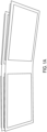
- Figures 1A , B and C are front, back and side views of the spacers inserted in an opening of a frame.
- Figure 1C the alignment guides to align the cover glass CG on top of the frame is shown.
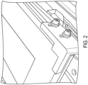
- Figure 2 shows a spacer, guides, and glass bonded to frame before clamping.
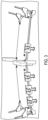
- Figure 3 shows the spacer, guides and glass bonded to the frame after clamping.
- the 1 st uniform bondline approach requires that the display lamination process is done after the cold-bending process as the spacer is inserted in the display window opening of the frame.
- the different approach is needed to achieve a uniform bondline control.
- a precise adhesive volume is laid down in the form of an adhesive bead [as a line (single pass or multiple passes to achieve desired height) or dots or other patterns] along the perimeter of the display window area as well as in the curved region(s).
- the adhesive bead is then cured using UV or thermal means to form a cured adhesive bead.
- the cured adhesive bead acts as a height control and determines the height of the structural adhesive in the 3D Cold formed curve laminate.
- the adhesive used for the adhesive bead must be chemically compatible with the structural adhesive.
- the adhesive bead can be laid down either on the flat CG or on the curved frame.
- Structural adhesive is dispensed onto either the flat GG or curved frame and the flat GG is then cold bent to the curved frame.
- the height of the adhesive bead determines the final adhesive bondline height in the 3D curved laminate.
- the uniform width of the adhesive bondline is achieved through dispensing the right volumetric amount of the structural adhesive for the given adhesive bezel width.
- Different adhesive materials such as Epoxy, Polyurethane, Acrylates, Silane Modified Polymers or Silicones can be used to form the adhesive bead.
- This adhesive bead method is already used for display lamination method, but what makes it unique in the 3D Cold bending process that the structural adhesive bezel width in 3D Cold formed laminate is very narrow, typically 5-10mm. Hence, very precise control of the adhesive bead is needed with minimum bead width being 1mm.
- Figure 4 shows the robotic adhesive dispenser.
- Figure 5 shows the cover material with a 1mm adhesive bead dispensed along the periphery of the part and in the central region for adhesive.
- Aspect (1) of this disclosure pertains to a method for controlling adhesive bondline while cold forming a curved decorated or non-decorated glass substrate, the method comprising: forming a frame to define a viewing area at least partially surrounded by the frame; shaping the frame to include at least one curvature; positioning a spacer proximate the frame, the spacer comprising: a border area; and a protrusion extending from the border area; engaging the border area of the spacer with the frame to insert the protrusion through the viewing area, wherein the protrusion extends beyond the frame a first distance; positioning an adhesive between the frame and the decorated or non-decorated glass substrate alongside the protrusion to control the bondline; engaging a decorated or non-decorated glass substrate with the adhesive and the protrusion to cold form the glass substrate to the shape of the frame; and one or both of vacuum forming and mechanically securing the decorated or non-decorated glass substrate to the spacer to hold the frame against the adhesive to maintain the bondline.
- Aspect (2) of this disclosure pertains to the method of Aspect (1), further comprising maintaining the first distance constant across the at least one curvature and the border area using the protrusion.
- Aspect (3) of this disclosure pertains to the method of Aspect (1) or Aspect (2), further comprising maintaining a width of the adhesive constant along the border area by engaging the frame with the protrusion along the viewing area.
- Aspect (4) of this disclosure pertains to the method of any one of Aspects (1) through (3), further comprising detachably coupling a spacer to the frame.
- Aspect (5) of this disclosure pertains to the method of Aspect (4), wherein detachably coupling the spacer to the frame comprises coupling the spacer to the frame with removable fasteners.
- Aspect (6) of this disclosure pertains to the method of any one of Aspects (1) through (5), wherein mechanically securing the glass substrate to the spacer comprises mechanically securing the glass substrate to the spacer by one or both of vacuum forming and mechanical clamping, in which as an example, further comprises positioning a backing layer against the decorated or non-decorated glass substrate opposite the spacer.
- Aspect (7) of this disclosure pertains to the method of Aspect (6), wherein the backing layer comprises an inverse frame having an inverse shape of the frame.
- Aspect (8) of this disclosure pertains to the method of Aspect (7), wherein the inverse frame comprises a plurality of pieces.
- Aspect (9) of this disclosure pertains to the method of Aspect (8), wherein at least one of the plurality of pieces has a shape including an inverse of the at least one curvature.
- Aspect (10) of this disclosure pertains to the method of Aspect (8) or Aspect (9), wherein at least one of the plurality of pieces covers the viewing area.
- Aspect (11) of this disclosure pertains to the method of any one of Aspects (6) through (10), wherein the backing layer comprises a non-stick material.
- Aspect (12) of this disclosure pertains to the method of any one of Aspects (6) through (11), wherein mechanically securing the decorated or non-decorated glass substrate to the spacer comprises clamping together the spacer and the backing layer.
- Aspect (13) of this disclosure pertains to the method of any one of Aspects (6) through (12), wherein mechanically securing the decorated or non-decorated glass substrate to the frame comprises clamping together the frame and the glass substrate without a backing layer.
- Aspect (14) of this disclosure pertains to the method of any one of Aspects (6) through (13), further comprising attaching guides to corners of the frame to align the decorated or non-decorated glass to the frame.
- Aspect (15) of this disclosure pertains to the method of any one of Aspects (1) through (14), wherein the spacer is formed of a non-stick material.
- Aspect (16) of this disclosure pertains to the method of any one of Aspects (1) through (15), wherein the frame is formed of a metal and the glass substrate is formed of soda lime glass, aluminosilicate glass, borosilicate glass, boroaluminosilicate glass, alkali-containing aluminosilicate glass, alkali-containing borosilicate glass, alkali-containing boroaluminosilicate glass, polycarbonate, polyimide or acrylics.
- Aspect (17) of this disclosure pertains to the method of any one of Aspects (1) through (16), wherein the adhesive is applied to the decorated or non-decorated glass substrate prior to engaging the decorated or non-decorated glass substrate with the protrusion of the spacer.
- Aspect (18) of this disclosure pertains to the method of any one of Aspects (1) through (17), wherein the adhesive is applied to the frame prior to engaging the decorated or non-decorated glass substrate with the protrusion of the spacer.
- Aspect (19) of this disclosure pertains to the method of any one of Aspects (1) through (18), further comprising priming the decorated or non-decorated glass at a point before the engaging.
- Aspect (20) of this disclosure pertains to the method of any one of Aspects (1) through (19), further comprising applying the adhesive manually or with a robot.
- Aspect (21) of this disclosure pertains to the method of any one of Aspects (1) through (20), further comprising: curing the adhesive, optionally to cold form the curved glass laminate; and removing the spacer from the frame.
- Aspect (22) of this disclosure pertains to the method of Aspect (21), further comprising curing the adhesive either at RT, with actinic radiation or by thermal means.
- Aspect (23) of this disclosure pertains to a method for controlling adhesive bondline while cold forming a curved decorated or non-decorated glass substrate, the method comprising: forming a frame to define a viewing area at least partially surrounded by the frame; shaping the frame to include at least one curvature; positioning a glass substrate proximate the frame; applying a spacer or gap controlling material along a perimeter of the glass substrate or a perimeter of the frame, the spacer or gap controlling material having a first height; positioning a structural adhesive between frame and the glass substrate such that the spacer or gap controlling material controls the bondline; engaging the glass substrate, the frame and the spacer or gap controlling material to cold form the glass substrate to the shape of the frame; and one or both of vacuum forming and mechanically securing the glass substrate to the frame to hold the frame against the structural adhesive to maintain the bondline.
- Aspect (24) of this disclosure pertains to the method of Aspect (23), wherein in one embodiment the spacer or gap controlling material is a curable adhesive bead.
- Aspect (25) of this disclosure pertains to the method of Aspect (23) or Aspect (24), further comprising maintaining the first distance constant across the at least one curvature and the viewing area using the adhesive bead.
- Aspect (26) of this disclosure pertains to the method of any one of Aspects (23) through (25), wherein mechanically securing the glass substrate to the frame comprises mechanically securing the glass substrate to the frame by one or both of vacuum forming and mechanical
- Aspect (27) of this disclosure pertains to the method of any one of Aspects (23) through (26), wherein the backing layer comprises an inverse frame having an inverse shape of the frame.
- Aspect (28) of this disclosure pertains to the method of any one of Aspects (23) through (27), wherein the backing layer comprises a non-stick material.
- Aspect (29) of this disclosure pertains to the method of any one of Aspects (23) through (28), wherein mechanically securing the decorated or non-decorated glass substrate to the frame comprises clamping together the frame and the backing layer.
- Aspect (30) of this disclosure pertains to the method of any one of Aspects (23) through (29), wherein mechanically securing the decorated or non-decorated glass substrate to the frame comprises clamping together the frame and the glass substrate without a backing layer.
- Aspect (31) of this disclosure pertains to the method of any one of Aspects (23) through (30), wherein the frame is formed of a metal and the glass substrate is formed of soda lime glass, aluminosilicate glass, borosilicate glass, boroaluminosilicate glass, alkali-containing aluminosilicate glass, alkali-containing borosilicate glass, alkali-containing boroaluminosilicate glass, polycarbonate, polyimide or acrylic.
- Aspect (32) of this disclosure pertains to the method of any one of Aspects (23) through (31), wherein the curable spacer material is applied to the frame.
- Aspect (33) of this disclosure pertains to the method of any one of Aspects (23) through (32), wherein the curable spacer material is applied to the decorated or non-decorated glass substrate.
- Aspect (34) of this disclosure pertains to the method of any one of Aspects (23) through (33), wherein the structural adhesive is applied to the frame.
- Aspect (35) of this disclosure pertains to the method of any one of Aspects (23) through (34), wherein the structural adhesive is applied to the decorated or non-decorated glass substrate.
- Aspect (36) of this disclosure pertains to the method of any one of Aspects (23) through (35), further comprising priming the decorated or non-decorated glass at a point before the engaging.
- Aspect (37) of this disclosure pertains to the method of any one of Aspects (23) through (36), further comprising applying the adhesive bead with a robot.
- Aspect (38) of this disclosure pertains to the method of any one of Aspects (23) through (37), further comprising controlling a height of the adhesive bead by controlling volumetric flow of adhesive.
- Aspect (39) of this disclosure pertains to the method of any one of Aspects (23) through (38), wherein the structural adhesive is chemically compatible with the spacer or gap controlling material.
- Aspect (40) of this disclosure pertains to the method of any one of Aspects (23) through (39), wherein the curable spacer material comprises an epoxy, a polyurethane, an acrylate, a silane modified polymer or a silicone, and the structural adhesive comprises an epoxy, a polyurethane, an acrylate, a silane modified polymer or a silicone.
- Aspect (41) of this disclosure pertains to the method of any one of Aspects (23) through (40), wherein the spacer or gap controlling material is segmented.
- Aspect (42) of this disclosure pertains to the method of any one of Aspects (23) through (41), wherein the spacer or gap controlling material is continuous.
- Aspect (43) of this disclosure pertains to the method of any one of Aspects (23) through (42), wherein the spacer or gap controlling material is multilayered.
- Aspect (44) of this disclosure pertains to the method of any one of Aspects (23) through (42), further comprising curing the structural adhesive .
- Aspect (45) of this disclosure pertains to the method of Aspect (44), further comprising curing the structural adhesive to cold form the curved glass laminate.
- Aspect (46) of this disclosure pertains to the method of Aspect (45), wherein the structural adhesive is either cured at room temperature, with actinic radiation or by thermal means. It will be apparent to those skilled in the art that various modifications and variations can be made without departing from the spirit or scope of the invention.
Landscapes
- Engineering & Computer Science (AREA)
- Chemical & Material Sciences (AREA)
- Mechanical Engineering (AREA)
- Materials Engineering (AREA)
- Organic Chemistry (AREA)
- Thermal Sciences (AREA)
- Physics & Mathematics (AREA)
- Plasma & Fusion (AREA)
- Ceramic Engineering (AREA)
- Life Sciences & Earth Sciences (AREA)
- Chemical Kinetics & Catalysis (AREA)
- Geochemistry & Mineralogy (AREA)
- General Chemical & Material Sciences (AREA)
- Adhesives Or Adhesive Processes (AREA)
- Joining Of Glass To Other Materials (AREA)
- Mounting And Adjusting Of Optical Elements (AREA)
- Connection Of Plates (AREA)
- Laminated Bodies (AREA)
- Lining Or Joining Of Plastics Or The Like (AREA)
Abstract
Description
- This application claims the benefit of priority under 35 U.S.C. § 119 of
U.S. Provisional Application Serial No. 62/754,581 filed on November 1, 2018 - Embodiments of this disclosure pertain to methods for uniform adhesive bondline control and in particular, to methods for uniform adhesive bondline control for forming cold-formed cover glass and cover glass and frame laminates.
- The present invention relates generally to the field of automotive interiors, and more particularly to 3D non-display areas in the vehicle. The invention is enabled by use of cold bent glass that is held in shape using a structural adhesive. The resultant product provides more appeal, higher reliability and improved safety to consumers, and opens design space for interior automotive designers.
- There is an ever-growing need and consumer thirst for technological innovation in the global automotive interiors industry. Vehicle manufactures are creating interiors that better connect, provide appeal, protect and safely inform today's drivers and passengers. There is already a trend towards larger displays including touch functionality in the new models from several OEMs. However, most of these displays consist of flat or two-dimensional (2D) plastic cover lenses. More recently, plastic is replaced by glass due to the superior functionality and user experience that glass materials provide.
- With growing interests from customers, and to maintain market positions the automotive industry is expected to move to three-dimensional (3D) surfaces made from glass. These 3D surfaces are expected to include both display and non-display area in the vehicle interior.
- Three-dimensional glass surfaces are conventionally formed via hot forming process. The process also is capable for forming curved 3D automotive interior displays. However, the process is energy intensive due to the high temperatures involved and adds significant cost to such products. Furthermore, there is a need to provide anti-reflection coatings on automotive interior display surfaces. Providing such coatings uniformly on a 3D surface utilizing known techniques is very challenging and also adds to the cost of the process.
- To address these issues, there is a need for cover glass for automotive interior applications that is curved using cold-bending techniques.
- One of the challenges with cold-bent glass is the extent to which it can be safely bent and installed in a vehicle. With the interior designers requiring tight curvatures, there is a need to develop a solution to safely implement glass in automotive interiors. The cold bending process imparts bending stress and changes the central tension in the glass. Further, the coefficient thermal expansion (CTE) of some cover glasses (e.g., aluminosilicate glasses) is about 7.88 x 10⁻⁶/°C, which is lower than the CTE of commonly used frame materials that are used to maintain the cold-bent shape of the glass. Such frame materials include Polycarbonate/Acrylonitrile Butadiene Styrene (PC/ABS) (with a CTE of about 70 to about 90 x 10-6/°C), Magnesium-alloys (with a CTE of about 25.2 x 10⁻⁶/°C to about 27.1 × 10⁻⁶/°C), Aluminum-alloys (with a CTE of about 20.4 x 10⁻⁶/°C to about 24.7 x 10⁻⁶/°C), stainless steel (with a CTE of about 12 x 10-6/°C to about 19.4 x 10⁻⁶/°C). This causes a CTE-mismatch induced stress which can be 5 times to about 100 times higher than cold bend stress of the glass depending on the viscoelastic or hyperelastic properties of the adhesive and the choice of the frame material. For the adhesive to have good tensile and shear load bearing capability and be able to accommodate the CTE-mismatch between adherends over -45°C to 100°C service temperature range, a two-component adhesive system with a minimum adhesive width of 3 mm and a minimum adhesive height of 0.3 mm is needed. The structural adhesives would typically be either an epoxy, polyurethane, silicone or silane modified polymer. These structural adhesives have high viscosity in the range of 20,000-600,000 cP and being in a liquid or paste consistency must be held in a uniform bondline at least till the handling strength of the adhesive is reached. Typically, in the industry, hollow or filled glass microbeads/microspacers or metal/plastic shims are used to maintain uniform bondline control. However, in 3D cold-bent laminate (including cover glass and a frame), as glass is one of the adherends, the use of glass microbeads or other hard material in the adhesive bondline results in micro-level scratches which affect the frangibility of a glass laminate.
- Embodiments of this disclosure pertain to methods for controlling the adhesive bondline (width and height of the adhesive) control in a 3D curved laminate formed by cold bending a cover material (which can include glass such as soda lime, aluminosilicate, borosilicate, alkaline earth boro-aluminosilicate glasses, or polymeric materials such as polyimide, polymethyl methacrylate, polycarbonate etc.). and bonding it to a curved frame (which can include a metal or plastic such as PC/ABS, polypropylene (PP)/ethylenepropylene-diene (EPDM) (PP-EPDM), carbon fiber reinforced plastic, glass reinforced plastic, etc.). One method for achieving this uniform adhesive bondline control is the use of a spacer. An alternative method utilizes applying a uniform cured adhesive bead.
- In one or more embodiments, the spacer may include Teflon®, polypropylene (PP), polyethylene (PE) or other non-stick coated metals, etc. In one or more embodiments, the spacer is inserted from a vehicle mounting side of the frame into an opening of the frame (which may include a display) and is temporarily attached to the frame using a fastener (e.g., screws, for example). The height of the spacer is greater than the frame so that it protrudes above the frame surface and acts as a physical stop that maintains the cover material at a specified distance off the frame surface and thus, helps control a uniform bondline height. In one or more embodiments, the method includes positioning an adhesive between the frame and the cover material alongside the raised spacer to control the bond line. In one or more embodiments, the width of the adhesive bondline is controlled as the adhesive path remains between the outside edge of the spacer and the edge of the cover material in the laminate. The method includes engaging the cover material with the adhesive and the spacer to cold-bend the cover material to the shape of the curved frame to form the cover material-frame laminate. After the adhesive is cured, the method includes removing the spacer from the cover material-frame laminate. In one or more embodiments, the method includes laminating a display to the cover material after the spacer is inserted in the opening of the frame, or after the spacer is removed from the laminate.
- A second aspect of the method includes laminating a display to a cover material in a flat configuration lamination on the flat cover glass and then cold-bending the cover material to the curved frame. In one or more embodiments, the lamination before cold-bending means there is no opening available for spacer. Accordingly, in one or more embodiments adhesive is dispensed in the form of an adhesive bead, as a line (formed by single pass or multiple passes to achieve desired height) or dots or other patterns. The adhesive bead is formed along the perimeter of the display area and on the regions to be curved by cold-bending. The adhesive bead is then cured using UV or thermal means to form a cured adhesive bead. The cured adhesive bead acts as a height control and determines the height of the structural adhesive in the curved cover glass-frame laminate. Different adhesive materials such as epoxy, polyurethane, acrylates and silicones can be used to form the adhesive bead. The height of the adhesive bead determines the final adhesive bondline height in the 3D curved laminate. The uniform width of the adhesive bondline is achieved through dispensing the right volumetric amount of the structural adhesive for the given adhesive bezel width.
- Additional features and advantages will be set forth in the detailed description which follows, and in part will be readily apparent to those skilled in the art from that description or recognized by practicing the embodiments as described herein, including the detailed description which follows, the claims, as well as the appended drawings.
- It is to be understood that both the foregoing general description and the following detailed description are merely exemplary, and are intended to provide an overview or framework to understanding the nature and character of the claims. The accompanying drawings are included to provide a further understanding, and are incorporated in and constitute a part of this specification. The drawings illustrate one or more embodiment(s), and together with the description serve to explain principles and operation of the various embodiments.
-
-
Figures 1A , B and C are front, back and side views of the spacers inserted in an opening of a frame, according to one or more embodiments. -
Figure 2 is a part with Teflon® spacers, guides, and glass bonded to frame before clamping, according to one or more embodiments. -
Figure 3 is the part ofFigure 2 after clamping; -
Figure 4 shows an adhesive bead being dispensed by Robotic adhesive dispenser, according to one or more embodiments. -
Figure 5 shows a cover material with a 1mm adhesive bead dispensed along the periphery of the part and in the central region for adhesive, according to one or more embodiments. - Reference will now be made in detail to various embodiments.
- In the proposed disclosure, two approaches have been identified to achieve a uniform adhesive bondline control in a 3D cold formed curved laminate. The 1st approach includes using spacer(s), more specifically, a spacer is inserted from the vehicle mounting side of the frame into the display window opening of the frame and is temporarily attached to the frame using easy-to-remove screws. Adhesive is applied either onto the curved frame or the flat cover glass (CG) using an adhesive dispenser (manual or pneumatic dispensing applicator or robotic dispensing equipment). The CG is placed on a vacuum chuck and the frame-Teflon® spacer assembly is aligned onto the CG. The height of the Teflon® insert above the frame surface acts as a physical stop as it keeps the CG a specified distance off the frame surface. A negative (or inverse) chuck with a flat plate bolted on top holds the entire laminate together. This assembly is held in place under vacuum till the handling strength of the adhesive (minutes to few hours duration depending on the adhesive) is reached. The width of the adhesive bondline is controlled as the adhesive path remains between the edge of the CG in the laminate and the outside edge of the Teflon® insert spacer. Thus, the Teflon® insert helps control a uniform bondline (width and height) and the Teflon® spacer is removed after the adhesive is cured. It is advisable to keep the curved laminate clamped till full-cure of the adhesive (hours to days duration depending on the adhesive) is reached.
- An alternative process can be considered for increased throughput: Teflon® spacer is inserted from the vehicle mounting side of the frame into the display window opening of the frame and is temporarily attached to the frame using easy-to-remove screws. The height of the Teflon® insert above the frame surface acts as a physical stop as it keeps the CG a specified distance off the frame surface. Teflon® guides are attached to the frame corners to assist with the alignment of the CG to the frame in the laminate. After the CG has been aligned to frame-Teflon® spacer assembly, an inverse frame (made of Teflon®, plastic or non-stick coated metal) is placed on top of the CG and the entire assembly is clamped together.
- In another variation: Instead of the inverse frame, a sectioned-frame approach is used. Here, Curved clamp plate with flat ends (made of Teflon, plastic or non-stick coated metal) is placed over the curved region(s) of the CG surface. This Curved clamp plate, designed to account for the adhesive height and bend radius at the curvature, applies uniformly distributed downward pressure and helps prevent any adhesive non-uniformity in the curved region(s) of the laminate. The Curved clamp plate can be secured to the frame along the edge using clamps. Further, to minimize any adhesive distortion over the flat display area of the CG, a flat 1-7mm sheet/thin plate (made of Teflon®, plastic or non-stick coated metal) can be placed which is then be secured to the frame along the edge using clamps. In yet another variation, instead of the flat sheet or thin plate, channels (made of Teflon®, plastic or non-stick coated metal) can be placed along the side/edges of the display window to clamp the flat display surface to the frame.
- The above processes produce higher throughput as it does not limit the number of parts made using the vacuum chuck. The clamps are kept on till full-cure of the adhesive (hours to days duration depending on the adhesive) is reached.
-
Figures 1A , B and C are front, back and side views of the spacers inserted in an opening of a frame. InFigure 1C , the alignment guides to align the cover glass CG on top of the frame is shown. -
Figure 2 shows a spacer, guides, and glass bonded to frame before clamping. -
Figure 3 shows the spacer, guides and glass bonded to the frame after clamping. - The 1st uniform bondline approach requires that the display lamination process is done after the cold-bending process as the spacer is inserted in the display window opening of the frame.
- When the display is laminated to the cover material, there is no opening accessable. Accordingly, in such embodiments, the different approach is needed to achieve a uniform bondline control. In one or more embodiments, n the 2nd approach, using a robotic dispenser a precise adhesive volume is laid down in the form of an adhesive bead [as a line (single pass or multiple passes to achieve desired height) or dots or other patterns] along the perimeter of the display window area as well as in the curved region(s). The adhesive bead is then cured using UV or thermal means to form a cured adhesive bead. The cured adhesive bead acts as a height control and determines the height of the structural adhesive in the 3D Cold formed curve laminate. The adhesive used for the adhesive bead must be chemically compatible with the structural adhesive. The adhesive bead can be laid down either on the flat CG or on the curved frame. Structural adhesive is dispensed onto either the flat GG or curved frame and the flat GG is then cold bent to the curved frame. The height of the adhesive bead determines the final adhesive bondline height in the 3D curved laminate. The uniform width of the adhesive bondline is achieved through dispensing the right volumetric amount of the structural adhesive for the given adhesive bezel width. Different adhesive materials such as Epoxy, Polyurethane, Acrylates, Silane Modified Polymers or Silicones can be used to form the adhesive bead. This adhesive bead method is already used for display lamination method, but what makes it unique in the 3D Cold bending process that the structural adhesive bezel width in 3D Cold formed laminate is very narrow, typically 5-10mm. Hence, very precise control of the adhesive bead is needed with minimum bead width being 1mm.
-
Figure 4 shows the robotic adhesive dispenser.Figure 5 shows the cover material with a 1mm adhesive bead dispensed along the periphery of the part and in the central region for adhesive. - Aspect (1) of this disclosure pertains to a method for controlling adhesive bondline while cold forming a curved decorated or non-decorated glass substrate, the method comprising: forming a frame to define a viewing area at least partially surrounded by the frame; shaping the frame to include at least one curvature; positioning a spacer proximate the frame, the spacer comprising: a border area; and a protrusion extending from the border area; engaging the border area of the spacer with the frame to insert the protrusion through the viewing area, wherein the protrusion extends beyond the frame a first distance; positioning an adhesive between the frame and the decorated or non-decorated glass substrate alongside the protrusion to control the bondline; engaging a decorated or non-decorated glass substrate with the adhesive and the protrusion to cold form the glass substrate to the shape of the frame; and one or both of vacuum forming and mechanically securing the decorated or non-decorated glass substrate to the spacer to hold the frame against the adhesive to maintain the bondline.
- Aspect (2) of this disclosure pertains to the method of Aspect (1), further comprising maintaining the first distance constant across the at least one curvature and the border area using the protrusion.
- Aspect (3) of this disclosure pertains to the method of Aspect (1) or Aspect (2), further comprising maintaining a width of the adhesive constant along the border area by engaging the frame with the protrusion along the viewing area.
- Aspect (4) of this disclosure pertains to the method of any one of Aspects (1) through (3), further comprising detachably coupling a spacer to the frame.
- Aspect (5) of this disclosure pertains to the method of Aspect (4), wherein detachably coupling the spacer to the frame comprises coupling the spacer to the frame with removable fasteners.
- Aspect (6) of this disclosure pertains to the method of any one of Aspects (1) through (5), wherein mechanically securing the glass substrate to the spacer comprises mechanically securing the glass substrate to the spacer by one or both of vacuum forming and mechanical clamping, in which as an example, further comprises positioning a backing layer against the decorated or non-decorated glass substrate opposite the spacer.
- Aspect (7) of this disclosure pertains to the method of Aspect (6), wherein the backing layer comprises an inverse frame having an inverse shape of the frame.
- Aspect (8) of this disclosure pertains to the method of Aspect (7), wherein the inverse frame comprises a plurality of pieces.
- Aspect (9) of this disclosure pertains to the method of Aspect (8), wherein at least one of the plurality of pieces has a shape including an inverse of the at least one curvature.
- Aspect (10) of this disclosure pertains to the method of Aspect (8) or Aspect (9), wherein at least one of the plurality of pieces covers the viewing area.
- Aspect (11) of this disclosure pertains to the method of any one of Aspects (6) through (10), wherein the backing layer comprises a non-stick material.
- Aspect (12) of this disclosure pertains to the method of any one of Aspects (6) through (11), wherein mechanically securing the decorated or non-decorated glass substrate to the spacer comprises clamping together the spacer and the backing layer.
- Aspect (13) of this disclosure pertains to the method of any one of Aspects (6) through (12), wherein mechanically securing the decorated or non-decorated glass substrate to the frame comprises clamping together the frame and the glass substrate without a backing layer.
- Aspect (14) of this disclosure pertains to the method of any one of Aspects (6) through (13), further comprising attaching guides to corners of the frame to align the decorated or non-decorated glass to the frame.
- Aspect (15) of this disclosure pertains to the method of any one of Aspects (1) through (14), wherein the spacer is formed of a non-stick material.
- Aspect (16) of this disclosure pertains to the method of any one of Aspects (1) through (15), wherein the frame is formed of a metal and the glass substrate is formed of soda lime glass, aluminosilicate glass, borosilicate glass, boroaluminosilicate glass, alkali-containing aluminosilicate glass, alkali-containing borosilicate glass, alkali-containing boroaluminosilicate glass, polycarbonate, polyimide or acrylics.
- Aspect (17) of this disclosure pertains to the method of any one of Aspects (1) through (16), wherein the adhesive is applied to the decorated or non-decorated glass substrate prior to engaging the decorated or non-decorated glass substrate with the protrusion of the spacer.
- Aspect (18) of this disclosure pertains to the method of any one of Aspects (1) through (17), wherein the adhesive is applied to the frame prior to engaging the decorated or non-decorated glass substrate with the protrusion of the spacer.
- Aspect (19) of this disclosure pertains to the method of any one of Aspects (1) through (18), further comprising priming the decorated or non-decorated glass at a point before the engaging.
- Aspect (20) of this disclosure pertains to the method of any one of Aspects (1) through (19), further comprising applying the adhesive manually or with a robot.
- Aspect (21) of this disclosure pertains to the method of any one of Aspects (1) through (20), further comprising: curing the adhesive, optionally to cold form the curved glass laminate; and removing the spacer from the frame.
- Aspect (22) of this disclosure pertains to the method of Aspect (21), further comprising curing the adhesive either at RT, with actinic radiation or by thermal means.
- Aspect (23) of this disclosure pertains to a method for controlling adhesive bondline while cold forming a curved decorated or non-decorated glass substrate, the method comprising: forming a frame to define a viewing area at least partially surrounded by the frame; shaping the frame to include at least one curvature; positioning a glass substrate proximate the frame; applying a spacer or gap controlling material along a perimeter of the glass substrate or a perimeter of the frame, the spacer or gap controlling material having a first height; positioning a structural adhesive between frame and the glass substrate such that the spacer or gap controlling material controls the bondline; engaging the glass substrate, the frame and the spacer or gap controlling material to cold form the glass substrate to the shape of the frame; and one or both of vacuum forming and mechanically securing the glass substrate to the frame to hold the frame against the structural adhesive to maintain the bondline.
- Aspect (24) of this disclosure pertains to the method of Aspect (23), wherein in one embodiment the spacer or gap controlling material is a curable adhesive bead.
- Aspect (25) of this disclosure pertains to the method of Aspect (23) or Aspect (24), further comprising maintaining the first distance constant across the at least one curvature and the viewing area using the adhesive bead.
- Aspect (26) of this disclosure pertains to the method of any one of Aspects (23) through (25), wherein mechanically securing the glass substrate to the frame comprises mechanically securing the glass substrate to the frame by one or both of vacuum forming and mechanical
- Aspect (27) of this disclosure pertains to the method of any one of Aspects (23) through (26), wherein the backing layer comprises an inverse frame having an inverse shape of the frame.
- Aspect (28) of this disclosure pertains to the method of any one of Aspects (23) through (27), wherein the backing layer comprises a non-stick material.
- Aspect (29) of this disclosure pertains to the method of any one of Aspects (23) through (28), wherein mechanically securing the decorated or non-decorated glass substrate to the frame comprises clamping together the frame and the backing layer.
- Aspect (30) of this disclosure pertains to the method of any one of Aspects (23) through (29), wherein mechanically securing the decorated or non-decorated glass substrate to the frame comprises clamping together the frame and the glass substrate without a backing layer.
- Aspect (31) of this disclosure pertains to the method of any one of Aspects (23) through (30), wherein the frame is formed of a metal and the glass substrate is formed of soda lime glass, aluminosilicate glass, borosilicate glass, boroaluminosilicate glass, alkali-containing aluminosilicate glass, alkali-containing borosilicate glass, alkali-containing boroaluminosilicate glass, polycarbonate, polyimide or acrylic.
- Aspect (32) of this disclosure pertains to the method of any one of Aspects (23) through (31), wherein the curable spacer material is applied to the frame.
- Aspect (33) of this disclosure pertains to the method of any one of Aspects (23) through (32), wherein the curable spacer material is applied to the decorated or non-decorated glass substrate.
- Aspect (34) of this disclosure pertains to the method of any one of Aspects (23) through (33), wherein the structural adhesive is applied to the frame.
- Aspect (35) of this disclosure pertains to the method of any one of Aspects (23) through (34), wherein the structural adhesive is applied to the decorated or non-decorated glass substrate.
- Aspect (36) of this disclosure pertains to the method of any one of Aspects (23) through (35), further comprising priming the decorated or non-decorated glass at a point before the engaging.
- Aspect (37) of this disclosure pertains to the method of any one of Aspects (23) through (36), further comprising applying the adhesive bead with a robot.
- Aspect (38) of this disclosure pertains to the method of any one of Aspects (23) through (37), further comprising controlling a height of the adhesive bead by controlling volumetric flow of adhesive.
- Aspect (39) of this disclosure pertains to the method of any one of Aspects (23) through (38), wherein the structural adhesive is chemically compatible with the spacer or gap controlling material.
- Aspect (40) of this disclosure pertains to the method of any one of Aspects (23) through (39), wherein the curable spacer material comprises an epoxy, a polyurethane, an acrylate, a silane modified polymer or a silicone, and the structural adhesive comprises an epoxy, a polyurethane, an acrylate, a silane modified polymer or a silicone.
- Aspect (41) of this disclosure pertains to the method of any one of Aspects (23) through (40), wherein the spacer or gap controlling material is segmented.
- Aspect (42) of this disclosure pertains to the method of any one of Aspects (23) through (41), wherein the spacer or gap controlling material is continuous.
- Aspect (43) of this disclosure pertains to the method of any one of Aspects (23) through (42), wherein the spacer or gap controlling material is multilayered.
- Aspect (44) of this disclosure pertains to the method of any one of Aspects (23) through (42), further comprising curing the structural adhesive .
- Aspect (45) of this disclosure pertains to the method of Aspect (44), further comprising curing the structural adhesive to cold form the curved glass laminate.
- Aspect (46) of this disclosure pertains to the method of Aspect (45), wherein the structural adhesive is either cured at room temperature, with actinic radiation or by thermal means.
It will be apparent to those skilled in the art that various modifications and variations can be made without departing from the spirit or scope of the invention.
Claims (15)
- A method for controlling adhesive bondline while cold forming a curved decorated or non-decorated glass substrate, the method comprising:positioning a glass substrate proximate a frame comprising a viewing area at least partially surrounded by the frame and at least one curvature;applying a spacer or gap controlling material along a perimeter of the glass substrate or a perimeter of the frame, the spacer or gap controlling material having a height;positioning a structural adhesive between frame and the glass substrate such that the spacer or gap controlling material controls the bondline;engaging the glass substrate, the frame and the spacer or gap controlling material to cold form the glass substrate to the shape of the frame; andone or both of vacuum forming and mechanically securing the glass substrate to the frame to hold the frame against the structural adhesive to maintain the bondline.
- The method of claim 1, wherein the spacer or gap controlling material is a curable adhesive bead.
- The method of claim 2, further comprising maintaining the height constant across the at least one curvature and the viewing area using the adhesive bead.
- The method of any one of claims 1-3, wherein mechanically securing the glass substrate to the frame comprises mechanically securing the glass substrate to the frame by one or both of vacuum forming and mechanical clamping.
- The method of any one of claims 1-3, wherein the method comprises providing a backing layer that comprises an inverse frame having an inverse shape of the frame.
- The method of claim 5, wherein the backing layer comprises a non-stick material.
- The method of claim 5, wherein mechanically securing the decorated or non-decorated glass substrate to the frame comprises clamping together the frame and the backing layer.
- The method of any one of claims 1-3, wherein mechanically securing the decorated or non-decorated glass substrate to the frame comprises clamping together the frame and the glass substrate without a backing layer.
- The method of any one of claims 1-3, wherein the frame is formed of a metal and the glass substrate is formed of soda lime glass, aluminosilicate glass, borosilicate glass, boroaluminosilicate glass, alkali-containing aluminosilicate glass, alkali-containing borosilicate glass, alkali-containing boroaluminosilicate glass, polycarbonate, polyimide or acrylic.
- The method of any one of claims 1-3, further comprising priming the decorated or non-decorated glass at a point before the engaging.
- The method of any one of claims 2-3, further comprising controlling a height of the adhesive bead by controlling volumetric flow of adhesive.
- The method of any one of claims 2-3, wherein the curable adhesive bead comprises an epoxy, a polyurethane, an acrylate, a silane modified polymer or a silicone, and the structural adhesive comprises an epoxy, a polyurethane, an acrylate, a silane modified polymer or a silicone.
- The method of any one of claims 1-3, wherein the spacer or gap controlling material is segmented and/or multilayered.
- The method of any one of claims 1-3, wherein the spacer or gap controlling material is continuous.
- The method of any of claims 1-14, the further comprising curing the structural adhesive.
Applications Claiming Priority (3)
| Application Number | Priority Date | Filing Date | Title |
|---|---|---|---|
| US201862754581P | 2018-11-01 | 2018-11-01 | |
| PCT/US2019/057395 WO2020092060A1 (en) | 2018-11-01 | 2019-10-22 | Methods for uniform adhesive bondline control for 3d cold formed curved laminate |
| EP19804905.8A EP3873734A1 (en) | 2018-11-01 | 2019-10-22 | Methods for uniform adhesive bondline control for 3d cold formed curved laminate |
Related Parent Applications (1)
| Application Number | Title | Priority Date | Filing Date |
|---|---|---|---|
| EP19804905.8A Division EP3873734A1 (en) | 2018-11-01 | 2019-10-22 | Methods for uniform adhesive bondline control for 3d cold formed curved laminate |
Publications (3)
| Publication Number | Publication Date |
|---|---|
| EP4465126A2 true EP4465126A2 (en) | 2024-11-20 |
| EP4465126A3 EP4465126A3 (en) | 2025-01-01 |
| EP4465126B1 EP4465126B1 (en) | 2025-12-17 |
Family
ID=68582329
Family Applications (2)
| Application Number | Title | Priority Date | Filing Date |
|---|---|---|---|
| EP24189439.3A Active EP4465126B1 (en) | 2018-11-01 | 2019-10-22 | Methods for uniform adhesive bondline control for 3d coldformed curved laminate |
| EP19804905.8A Withdrawn EP3873734A1 (en) | 2018-11-01 | 2019-10-22 | Methods for uniform adhesive bondline control for 3d cold formed curved laminate |
Family Applications After (1)
| Application Number | Title | Priority Date | Filing Date |
|---|---|---|---|
| EP19804905.8A Withdrawn EP3873734A1 (en) | 2018-11-01 | 2019-10-22 | Methods for uniform adhesive bondline control for 3d cold formed curved laminate |
Country Status (7)
| Country | Link |
|---|---|
| US (1) | US12115766B2 (en) |
| EP (2) | EP4465126B1 (en) |
| JP (1) | JP7454570B2 (en) |
| KR (1) | KR20210087053A (en) |
| CN (1) | CN113165334B (en) |
| TW (1) | TWI851614B (en) |
| WO (1) | WO2020092060A1 (en) |
Families Citing this family (5)
| Publication number | Priority date | Publication date | Assignee | Title |
|---|---|---|---|---|
| WO2020223056A1 (en) * | 2019-04-29 | 2020-11-05 | Corning Incorporated | Cold formed 3d product and processes using vacuum chuck |
| EP4164994A1 (en) * | 2020-06-11 | 2023-04-19 | Corning Incorporated | Glass articles having adhesive bead with high aspect ratio and method of preparing same |
| US20220324201A1 (en) * | 2021-03-31 | 2022-10-13 | Corning Incorporated | Glass article having a plastic frame with enhanced reliability against delamination |
| TWM614158U (en) * | 2021-04-15 | 2021-07-01 | 邑富股份有限公司 | Glue dispenser dispensing switch and double liquid dispensing equipment with the same |
| CN115539472A (en) * | 2022-12-02 | 2022-12-30 | 常州市新创智能科技有限公司 | Composite board body and connecting structure thereof |
Family Cites Families (94)
| Publication number | Priority date | Publication date | Assignee | Title |
|---|---|---|---|---|
| US2480642A (en) * | 1947-11-26 | 1949-08-30 | James W Galloway | Prefabricated section for buildings and a seal for joints between sections |
| GB1359169A (en) * | 1971-05-21 | 1974-07-10 | Glaverbel | Articles incorporating glass sheets |
| US3920433A (en) | 1973-06-25 | 1975-11-18 | Columbine Glass Company | Apparatus and method for improved glassware coating |
| DE2758581C2 (en) | 1977-12-29 | 1980-01-03 | Bfg Glassgroup, Paris | Windshields, in particular for motor vehicles, with an inner pane made of chemically toughened silicate glass |
| DE3012007A1 (en) | 1980-03-28 | 1981-10-08 | Gebr. Happich Gmbh, 5600 Wuppertal | FOAM BODY, IN PARTICULAR DASHBOARD FOR MOTOR VEHICLES |
| JPS59185246U (en) * | 1983-05-25 | 1984-12-08 | トヨタ自動車株式会社 | Vehicle windshield glass dam adhesion device |
| DE3501490A1 (en) * | 1985-01-18 | 1986-07-24 | Daimler-Benz Ag, 7000 Stuttgart | GLASS DISC GLUED IN THE FRAME OF A CAR BODY BY MEANS OF AN ELASTOMER NETWORKED ADHESIVE |
| BE1000350A5 (en) | 1987-02-27 | 1988-11-08 | Saint Roch Glaceries | Hanger glass panel. |
| LU87241A1 (en) | 1988-06-15 | 1990-02-28 | Glaverbel | METHOD FOR INCREASING THE PENETRATION RESISTANCE THROUGH A GLAZED BAY AND GLAZING WITH STRENGTHENED BREAKING RESISTANCE |
| JP3059337B2 (en) | 1994-04-21 | 2000-07-04 | シャープ株式会社 | Semiconductor device and manufacturing method thereof |
| DE4415878C2 (en) | 1994-05-05 | 1996-08-14 | Bayerische Motoren Werke Ag | Laminated glass pane, in particular for vehicles |
| JP3364081B2 (en) | 1995-02-16 | 2003-01-08 | 株式会社半導体エネルギー研究所 | Method for manufacturing semiconductor device |
| NL1003537C2 (en) | 1996-07-08 | 1998-01-12 | Holland Railconsult B V | Method for manufacturing curved glazing. |
| JPH1029829A (en) * | 1996-07-17 | 1998-02-03 | Asahi Glass Co Ltd | Glass sheet bending apparatus, bending mold, and method of manufacturing the same |
| JPH1160293A (en) | 1997-08-06 | 1999-03-02 | Nippon Sheet Glass Co Ltd | Laminated glass and automotive window construction |
| JPH11126029A (en) | 1997-10-22 | 1999-05-11 | Yazaki Corp | display |
| US6582799B1 (en) | 1999-06-02 | 2003-06-24 | Ppg Industries Ohio, Inc. | Laminated transparency |
| US7114541B2 (en) | 2000-09-07 | 2006-10-03 | Gesim Gesselschaft Fur Silizium-Mikrosysteme Mbh | Method for producing a 3-D micro flow cell and a 3-D micro flow cell |
| US6953735B2 (en) | 2001-12-28 | 2005-10-11 | Semiconductor Energy Laboratory Co., Ltd. | Method for fabricating a semiconductor device by transferring a layer to a support with curvature |
| JP4132949B2 (en) | 2002-05-02 | 2008-08-13 | ハイテックエンジニアリング株式会社 | Method and apparatus for producing bent glass |
| JP2004284839A (en) | 2003-03-19 | 2004-10-14 | Nippon Sheet Glass Co Ltd | Laminated glass |
| DE102004022008A1 (en) | 2003-05-01 | 2004-12-16 | Europtec Gmbh | Glass for a tachometer cover in a vehicle comprises a solid composite of laminated layers consisting of a layer with a first thin flat glass, a layer with a flexible film, and a layer with a second thin flat glass |
| US20090033859A1 (en) | 2005-06-21 | 2009-02-05 | Michihisa Ueda | Liquid Crystal Spacer, Spacer Diffusion Liquid, Liquid Crystal Display Device Manufacturing Method, and Liquid Crystal Display Device |
| US7871664B2 (en) | 2006-03-23 | 2011-01-18 | Guardian Industries Corp. | Parabolic trough or dish reflector for use in concentrating solar power apparatus and method of making same |
| US20070223121A1 (en) | 2006-03-23 | 2007-09-27 | Centre Luxembourgeois De Recherches Pour Le Verre Et La Ceramique S.A. (C.R.V.C.) | Method of making reflector for solar collector or the like and corresponding product |
| US8677782B2 (en) | 2006-07-25 | 2014-03-25 | Guardian Industries Corp. | Method of making glass including surface treatment with aluminum chloride at or just prior to annealing LEHR |
| US20080022721A1 (en) | 2006-07-25 | 2008-01-31 | Bernd Disteldorf | Method of making glass including surface treatment with aluminum chloride at or just prior to annealing lehr |
| EP2053583A4 (en) | 2006-07-27 | 2010-06-02 | Sharp Kk | Display device |
| US20090179840A1 (en) | 2006-07-27 | 2009-07-16 | Sharp Kabushiki Kaisha | Display device |
| BRPI0806926A2 (en) | 2007-02-06 | 2014-04-29 | Saint Gobain | INSULATING GLASS ELEMENT. |
| CN101678580B (en) | 2007-05-01 | 2014-03-26 | 埃克阿泰克有限责任公司 | Organic glass plate with UV-curable printed pattern and its manufacturing method |
| FR2918411B1 (en) | 2007-07-06 | 2013-10-18 | Faurecia Sys Echappement | THERMOEXPANSIBLE HOLDING TABLE. |
| CN101684032A (en) | 2008-09-27 | 2010-03-31 | 深圳市三鑫特种玻璃技术股份有限公司石岩生产中心 | Glass cold-bending method |
| CN102566841B (en) | 2008-10-31 | 2015-04-15 | 宸美(厦门)光电有限公司 | Structure of curved capacitive touch control panel |
| CN102574371B (en) | 2009-10-20 | 2015-10-07 | 旭硝子株式会社 | Glass laminate, the display unit panel being with supporting mass, display unit panel, display unit and their manufacture method |
| TWI531811B (en) | 2010-10-28 | 2016-05-01 | 康寧公司 | Video screen cover glass illumination |
| TWI467427B (en) | 2011-10-07 | 2015-01-01 | Young Optics Inc | Touch display apparatus |
| KR102044359B1 (en) | 2011-10-10 | 2019-11-13 | 코닝 인코포레이티드 | Apparatus and method for tight bending thin glass sheets |
| US8833106B2 (en) | 2012-09-18 | 2014-09-16 | Corning Incorporated | Thermo-mechanical reforming method and system and mechanical reforming tool |
| SG191883A1 (en) | 2011-10-18 | 2013-08-30 | Fischer Technology Pte Ltd | A method of moulding |
| US8549885B2 (en) | 2011-11-23 | 2013-10-08 | Corning Incorporated | Process and system for precision glass sheet bending |
| JP5835038B2 (en) | 2012-03-15 | 2015-12-24 | 日本電気硝子株式会社 | Glass material-resin material laminate |
| EP2679551A1 (en) | 2012-06-28 | 2014-01-01 | Corning Incorporated | Process and system for fine tuning precision glass sheet bending |
| US20140014260A1 (en) | 2012-07-12 | 2014-01-16 | Dipakbin Qasem Chowdhury | Laminated structures and methods of manufacturing laminated structures |
| CN105102217A (en) | 2012-10-05 | 2015-11-25 | 康宁股份有限公司 | Glass/metal laminated structure and method of making laminated structure |
| US9045364B2 (en) | 2012-11-30 | 2015-06-02 | Owens-Brockway Glass Container Inc | Surface treatment process for glass containers |
| EP3527363A1 (en) | 2013-01-07 | 2019-08-21 | Corning Incorporated | Strengthened laminated glass structures |
| JP5976561B2 (en) | 2013-02-04 | 2016-08-23 | 株式会社東海理化電機製作所 | Operating device |
| JP5997655B2 (en) | 2013-04-26 | 2016-09-28 | 矢崎総業株式会社 | Vehicle display device |
| DE102013214108B4 (en) | 2013-07-18 | 2023-05-17 | Bayerische Motoren Werke Aktiengesellschaft | Three-dimensionally curved shaped glass body and method for its production |
| WO2017019851A1 (en) | 2015-07-30 | 2017-02-02 | Corning Incorporated | Thermally strengthened automotive glass |
| JP6431069B2 (en) | 2013-08-29 | 2018-11-28 | コーニング インコーポレイテッド | Thin glass laminate structure |
| EP3466676B1 (en) | 2013-12-06 | 2020-08-05 | Corning Incorporated | Methods for forming patterns in thin glass laminate structures |
| FR3017073B1 (en) | 2014-02-03 | 2016-03-04 | Holdham | INFORMATION SHEET, INTENDED TO BE INTRODUCED BETWEEN TWO PAGES OF A STATIONERY PRODUCT, SUCH AS A NOTEBOOK |
| CN203825589U (en) | 2014-04-10 | 2014-09-10 | 上海博泰悦臻电子设备制造有限公司 | Curved touch display screen |
| KR102393391B1 (en) | 2014-07-10 | 2022-05-02 | 코닝 인코포레이티드 | Cold formed glass applique |
| JP6213737B2 (en) | 2014-07-30 | 2017-10-18 | 豊田合成株式会社 | Touch panel device and method for manufacturing touch panel device |
| WO2016044360A1 (en) | 2014-09-17 | 2016-03-24 | Corning Incorporated | Curved liquid crystal display panel and process of manufacture |
| KR102584492B1 (en) | 2014-10-08 | 2023-10-04 | 코닝 인코포레이티드 | Glasses and glass ceramics including a metal oxide concentration gradient |
| CN104503629A (en) | 2015-01-19 | 2015-04-08 | 欧浦登(顺昌)光学有限公司 | Fully-glued curved surface touch control display screen and manufacturing process thereof |
| CN204463066U (en) | 2015-01-19 | 2015-07-08 | 欧浦登(顺昌)光学有限公司 | A full-fit curved touch display |
| DE112016000631B4 (en) | 2015-02-05 | 2023-08-31 | AGC Inc. | Cover glass with curved surface, method for the production thereof and vehicle interior display element |
| JP2015092422A (en) | 2015-02-20 | 2015-05-14 | 株式会社ミクロ技術研究所 | Curved touch panel |
| DE112016000910T5 (en) | 2015-02-25 | 2017-11-16 | Asahi Glass Company, Limited | Curved cover glass and method for its manufacture and glass element, display device and curved glass |
| JP2016173794A (en) | 2015-03-18 | 2016-09-29 | 小島プレス工業株式会社 | Vehicle-mounted touch sensor and manufacturing method thereof |
| CN104843976B (en) | 2015-04-01 | 2018-02-27 | 桂林电子科技大学 | A kind of 3D curved surfaces ultra-thin glass bend molding apparatus and manufacture method |
| JP2016207200A (en) | 2015-04-20 | 2016-12-08 | ホシデン株式会社 | Touch panel and manufacturing method thereof |
| KR20160124665A (en) | 2015-04-20 | 2016-10-28 | 호시덴 가부시기가이샤 | Touch panel and manufacturing method thereof |
| KR102300081B1 (en) | 2015-04-27 | 2021-09-08 | 삼성디스플레이 주식회사 | Bonding appratus and method of manufacturing curved display device using the same |
| EP3295241A1 (en) | 2015-05-11 | 2018-03-21 | Corning Incorporated | Surface display units with opaque screen |
| KR20180014753A (en) | 2015-06-02 | 2018-02-09 | 코닝 인코포레이티드 | Light-reactive thin glass laminate |
| JP6768009B2 (en) | 2015-06-02 | 2020-10-14 | コーニング インコーポレイテッド | Glass laminate with panes having a glass-glass laminate structure |
| KR20180016431A (en) | 2015-06-02 | 2018-02-14 | 코닝 인코포레이티드 | Multifunctional material system for surface display units |
| JP2018526663A (en) | 2015-06-02 | 2018-09-13 | コーニング インコーポレイテッド | Aesthetic surface and display device having such a surface |
| TW201710113A (en) | 2015-06-02 | 2017-03-16 | 康寧公司 | Vehicle projection system |
| US10286631B2 (en) | 2015-06-03 | 2019-05-14 | Precision Glass Bending Corporation | Bent, veneer-encapsulated heat-treated safety glass panels and methods of manufacture |
| KR102411046B1 (en) | 2015-06-05 | 2022-06-20 | 엘지디스플레이 주식회사 | Bar type display apparatus and vehicle comprising the same |
| US9895975B2 (en) | 2015-06-05 | 2018-02-20 | Lg Display Co., Ltd. | Bar type display apparatus and vehicle comprising the same |
| FR3037890B1 (en) | 2015-06-29 | 2019-03-15 | Faurecia Sieges D'automobile | COMPRISING A CLOTHING ELEMENT FOR A MOTOR VEHICLE SEAT OR A MOTOR VEHICLE HABITACLE |
| CN107848265B (en) | 2015-07-10 | 2020-09-08 | 康宁股份有限公司 | cold formed laminate |
| CN105511127B (en) | 2016-01-26 | 2020-11-06 | 深圳市华星光电技术有限公司 | Curved Display Lamination Equipment |
| EP3426614B1 (en) | 2016-03-09 | 2024-11-20 | Corning Incorporated | Cold forming of complexly curved glass articles |
| KR102544091B1 (en) | 2016-06-28 | 2023-06-16 | 코닝 인코포레이티드 | Laminating thin strengthened glass to curved molded plastic surface for decorative and display cover application |
| JP7071294B2 (en) * | 2016-07-05 | 2022-05-18 | コーニング インコーポレイテッド | Cold-formed glass articles and their assembly methods |
| KR102610962B1 (en) | 2016-08-02 | 2023-12-08 | 삼성디스플레이 주식회사 | Method for treating glass substrate |
| DE102016215546A1 (en) | 2016-08-18 | 2018-02-22 | Faurecia Innenraum Systeme Gmbh | Method for producing a vehicle interior trim part and vehicle interior trim part |
| DE102016218916A1 (en) | 2016-09-29 | 2018-03-29 | Faurecia Innenraum Systeme Gmbh | Covering part for a vehicle interior |
| US10953644B2 (en) | 2016-10-20 | 2021-03-23 | Corning Incorporated | Cold formed 3D cover glass articles and forming process to make the same |
| EP3532442A1 (en) | 2016-10-25 | 2019-09-04 | Corning Incorporated | Cold-form glass lamination to a display |
| US10737468B2 (en) | 2016-10-28 | 2020-08-11 | Plaskolite Massachusetts, Llc | High security polycarbonate laminate windows with insulated glazing units |
| CN110520331A (en) | 2016-12-30 | 2019-11-29 | 康宁公司 | Glass-covered vehicle interior system and method of forming the same |
| TWI771357B (en) | 2017-01-03 | 2022-07-21 | 美商康寧公司 | Vehicle interior systems having a curved cover glass and display or touch panel and methods for forming the same |
| TWI778025B (en) | 2017-02-24 | 2022-09-21 | 碁米庫斯生物科技股份有限公司 | Antibiotic testing and screening system |
| CN108032595B (en) | 2017-12-04 | 2019-10-18 | 福耀玻璃工业集团股份有限公司 | A production method of ultra-thin laminated glass and ultra-thin laminated glass |
-
2019
- 2019-10-22 EP EP24189439.3A patent/EP4465126B1/en active Active
- 2019-10-22 US US17/290,938 patent/US12115766B2/en active Active
- 2019-10-22 JP JP2021523811A patent/JP7454570B2/en active Active
- 2019-10-22 CN CN201980080562.2A patent/CN113165334B/en active Active
- 2019-10-22 KR KR1020217016028A patent/KR20210087053A/en not_active Withdrawn
- 2019-10-22 WO PCT/US2019/057395 patent/WO2020092060A1/en not_active Ceased
- 2019-10-22 EP EP19804905.8A patent/EP3873734A1/en not_active Withdrawn
- 2019-11-01 TW TW108139635A patent/TWI851614B/en active
Also Published As
| Publication number | Publication date |
|---|---|
| CN113165334B (en) | 2023-12-22 |
| WO2020092060A1 (en) | 2020-05-07 |
| TWI851614B (en) | 2024-08-11 |
| JP2022509021A (en) | 2022-01-20 |
| US20210370659A1 (en) | 2021-12-02 |
| JP7454570B2 (en) | 2024-03-22 |
| EP4465126B1 (en) | 2025-12-17 |
| CN113165334A (en) | 2021-07-23 |
| TW202035166A (en) | 2020-10-01 |
| EP4465126A3 (en) | 2025-01-01 |
| EP3873734A1 (en) | 2021-09-08 |
| KR20210087053A (en) | 2021-07-09 |
| US12115766B2 (en) | 2024-10-15 |
Similar Documents
| Publication | Publication Date | Title |
|---|---|---|
| EP4465126B1 (en) | Methods for uniform adhesive bondline control for 3d coldformed curved laminate | |
| US12595201B2 (en) | Cold-form glass lamination to a display | |
| US12103397B2 (en) | Vehicle interior systems having a curved cover glass with improved reliability and methods for forming the same | |
| JP7051720B2 (en) | Laminating thin tempered glass on curved molded plastic surfaces for decorative and display cover applications | |
| US12011914B2 (en) | Curved glass constructions and methods for forming same | |
| WO2009054168A1 (en) | Display device and method for production thereof | |
| CN107757516A (en) | For manufacturing the method and vehicle interior part of vehicle interior part | |
| CN113442543A (en) | Bonding device and bonding method of display substrate | |
| US20090029100A1 (en) | Method for producing rigid laminates for optical applications | |
| WO2016074917A1 (en) | Method and apparatus for optical bonding, and a display | |
| JP2015106045A (en) | Flat display device and manufacturing method thereof | |
| EP3906153A1 (en) | Three-dimensional cold formed curved composites | |
| SE503808C2 (en) | Method and apparatus for bending thermoplastic sheets and manufacture of laminated light-transmitting panels | |
| CN108962018A (en) | The method and one screen that a kind of flat glass and curved-surface display mould group are bonded entirely | |
| US20250001749A1 (en) | Methods for uniform adhesive bondline control for 3d cold formed curved laminate | |
| US20220203835A1 (en) | Cold formed 3d product and processes using vacuum chuck | |
| CN106985480A (en) | It is a kind of for optical material of full attaching process and its preparation method and application | |
| KR102919267B1 (en) | Adhesive delivery system | |
| US11613069B2 (en) | Method of forming a curved, rigid display article | |
| KR20150102436A (en) | The apparatus for attaching the flexible sheet to others | |
| CN102148170A (en) | Substrate attaching method | |
| JP2026505986A (en) | Display system with spacers disposed between a frame and a display back panel and related methods | |
| WO2024120714A1 (en) | Method of obtaining a dynamic laminated glazing |
Legal Events
| Date | Code | Title | Description |
|---|---|---|---|
| PUAI | Public reference made under article 153(3) epc to a published international application that has entered the european phase |
Free format text: ORIGINAL CODE: 0009012 |
|
| STAA | Information on the status of an ep patent application or granted ep patent |
Free format text: STATUS: THE APPLICATION HAS BEEN PUBLISHED |
|
| AC | Divisional application: reference to earlier application |
Ref document number: 3873734 Country of ref document: EP Kind code of ref document: P |
|
| AK | Designated contracting states |
Kind code of ref document: A2 Designated state(s): AL AT BE BG CH CY CZ DE DK EE ES FI FR GB GR HR HU IE IS IT LI LT LU LV MC MK MT NL NO PL PT RO RS SE SI SK SM TR |
|
| REG | Reference to a national code |
Ref country code: DE Ref legal event code: R079 Free format text: PREVIOUS MAIN CLASS: G02F0001133900 Ipc: B32B0007140000 Ref document number: 602019079479 Country of ref document: DE |
|
| PUAL | Search report despatched |
Free format text: ORIGINAL CODE: 0009013 |
|
| AK | Designated contracting states |
Kind code of ref document: A3 Designated state(s): AL AT BE BG CH CY CZ DE DK EE ES FI FR GB GR HR HU IE IS IT LI LT LU LV MC MK MT NL NO PL PT RO RS SE SI SK SM TR |
|
| RIC1 | Information provided on ipc code assigned before grant |
Ipc: G02F 1/1339 20060101ALI20241126BHEP Ipc: G02F 1/1333 20060101ALI20241126BHEP Ipc: B32B 37/14 20060101ALI20241126BHEP Ipc: B32B 37/12 20060101ALI20241126BHEP Ipc: B32B 37/10 20060101ALI20241126BHEP Ipc: B32B 17/06 20060101ALI20241126BHEP Ipc: B32B 7/14 20060101AFI20241126BHEP |
|
| STAA | Information on the status of an ep patent application or granted ep patent |
Free format text: STATUS: REQUEST FOR EXAMINATION WAS MADE |
|
| GRAP | Despatch of communication of intention to grant a patent |
Free format text: ORIGINAL CODE: EPIDOSNIGR1 |
|
| STAA | Information on the status of an ep patent application or granted ep patent |
Free format text: STATUS: GRANT OF PATENT IS INTENDED |
|
| 17P | Request for examination filed |
Effective date: 20250611 |
|
| RIC1 | Information provided on ipc code assigned before grant |
Ipc: B32B 7/14 20060101AFI20250627BHEP Ipc: B32B 17/06 20060101ALI20250627BHEP Ipc: B32B 37/10 20060101ALI20250627BHEP Ipc: B32B 37/12 20060101ALI20250627BHEP Ipc: B32B 37/14 20060101ALI20250627BHEP Ipc: G02F 1/1333 20060101ALI20250627BHEP Ipc: G02F 1/1339 20060101ALI20250627BHEP |
|
| INTG | Intention to grant announced |
Effective date: 20250711 |
|
| GRAS | Grant fee paid |
Free format text: ORIGINAL CODE: EPIDOSNIGR3 |
|
| GRAA | (expected) grant |
Free format text: ORIGINAL CODE: 0009210 |
|
| STAA | Information on the status of an ep patent application or granted ep patent |
Free format text: STATUS: THE PATENT HAS BEEN GRANTED |
|
| AC | Divisional application: reference to earlier application |
Ref document number: 3873734 Country of ref document: EP Kind code of ref document: P |
|
| AK | Designated contracting states |
Kind code of ref document: B1 Designated state(s): AL AT BE BG CH CY CZ DE DK EE ES FI FR GB GR HR HU IE IS IT LI LT LU LV MC MK MT NL NO PL PT RO RS SE SI SK SM TR |
|
| REG | Reference to a national code |
Ref country code: CH Ref legal event code: F10 Free format text: ST27 STATUS EVENT CODE: U-0-0-F10-F00 (AS PROVIDED BY THE NATIONAL OFFICE) Effective date: 20251217 Ref country code: GB Ref legal event code: FG4D |
|
| P01 | Opt-out of the competence of the unified patent court (upc) registered |
Free format text: CASE NUMBER: UPC_APP_0014454_4465126/2025 Effective date: 20251124 |
|
| REG | Reference to a national code |
Ref country code: DE Ref legal event code: R096 Ref document number: 602019079479 Country of ref document: DE |
|
| REG | Reference to a national code |
Ref country code: LT Ref legal event code: MG9D |
|
| PG25 | Lapsed in a contracting state [announced via postgrant information from national office to epo] |
Ref country code: NO Free format text: LAPSE BECAUSE OF FAILURE TO SUBMIT A TRANSLATION OF THE DESCRIPTION OR TO PAY THE FEE WITHIN THE PRESCRIBED TIME-LIMIT Effective date: 20260317 |
|
| PG25 | Lapsed in a contracting state [announced via postgrant information from national office to epo] |
Ref country code: FI Free format text: LAPSE BECAUSE OF FAILURE TO SUBMIT A TRANSLATION OF THE DESCRIPTION OR TO PAY THE FEE WITHIN THE PRESCRIBED TIME-LIMIT Effective date: 20251217 Ref country code: HR Free format text: LAPSE BECAUSE OF FAILURE TO SUBMIT A TRANSLATION OF THE DESCRIPTION OR TO PAY THE FEE WITHIN THE PRESCRIBED TIME-LIMIT Effective date: 20251217 |
|
| PG25 | Lapsed in a contracting state [announced via postgrant information from national office to epo] |
Ref country code: RS Free format text: LAPSE BECAUSE OF FAILURE TO SUBMIT A TRANSLATION OF THE DESCRIPTION OR TO PAY THE FEE WITHIN THE PRESCRIBED TIME-LIMIT Effective date: 20260317 |
|
| REG | Reference to a national code |
Ref country code: NL Ref legal event code: MP Effective date: 20251217 |
|
| PG25 | Lapsed in a contracting state [announced via postgrant information from national office to epo] |
Ref country code: LV Free format text: LAPSE BECAUSE OF FAILURE TO SUBMIT A TRANSLATION OF THE DESCRIPTION OR TO PAY THE FEE WITHIN THE PRESCRIBED TIME-LIMIT Effective date: 20251217 |
|
| PG25 | Lapsed in a contracting state [announced via postgrant information from national office to epo] |
Ref country code: BG Free format text: LAPSE BECAUSE OF FAILURE TO SUBMIT A TRANSLATION OF THE DESCRIPTION OR TO PAY THE FEE WITHIN THE PRESCRIBED TIME-LIMIT Effective date: 20251217 |
|
| REG | Reference to a national code |
Ref country code: AT Ref legal event code: MK05 Ref document number: 1868153 Country of ref document: AT Kind code of ref document: T Effective date: 20251217 |
|
| PG25 | Lapsed in a contracting state [announced via postgrant information from national office to epo] |
Ref country code: NL Free format text: LAPSE BECAUSE OF FAILURE TO SUBMIT A TRANSLATION OF THE DESCRIPTION OR TO PAY THE FEE WITHIN THE PRESCRIBED TIME-LIMIT Effective date: 20251217 |
|
| PG25 | Lapsed in a contracting state [announced via postgrant information from national office to epo] |
Ref country code: LT Free format text: LAPSE BECAUSE OF FAILURE TO SUBMIT A TRANSLATION OF THE DESCRIPTION OR TO PAY THE FEE WITHIN THE PRESCRIBED TIME-LIMIT Effective date: 20251217 |
|
| PG25 | Lapsed in a contracting state [announced via postgrant information from national office to epo] |
Ref country code: SM Free format text: LAPSE BECAUSE OF FAILURE TO SUBMIT A TRANSLATION OF THE DESCRIPTION OR TO PAY THE FEE WITHIN THE PRESCRIBED TIME-LIMIT Effective date: 20251217 |
|
| PG25 | Lapsed in a contracting state [announced via postgrant information from national office to epo] |
Ref country code: ES Free format text: LAPSE BECAUSE OF FAILURE TO SUBMIT A TRANSLATION OF THE DESCRIPTION OR TO PAY THE FEE WITHIN THE PRESCRIBED TIME-LIMIT Effective date: 20251217 |
|
| PG25 | Lapsed in a contracting state [announced via postgrant information from national office to epo] |
Ref country code: PL Free format text: LAPSE BECAUSE OF FAILURE TO SUBMIT A TRANSLATION OF THE DESCRIPTION OR TO PAY THE FEE WITHIN THE PRESCRIBED TIME-LIMIT Effective date: 20251217 |
|
| PG25 | Lapsed in a contracting state [announced via postgrant information from national office to epo] |
Ref country code: IT Free format text: LAPSE BECAUSE OF FAILURE TO SUBMIT A TRANSLATION OF THE DESCRIPTION OR TO PAY THE FEE WITHIN THE PRESCRIBED TIME-LIMIT Effective date: 20251217 |
|
| PG25 | Lapsed in a contracting state [announced via postgrant information from national office to epo] |
Ref country code: AT Free format text: LAPSE BECAUSE OF FAILURE TO SUBMIT A TRANSLATION OF THE DESCRIPTION OR TO PAY THE FEE WITHIN THE PRESCRIBED TIME-LIMIT Effective date: 20251217 |
|
| PG25 | Lapsed in a contracting state [announced via postgrant information from national office to epo] |
Ref country code: EE Free format text: LAPSE BECAUSE OF FAILURE TO SUBMIT A TRANSLATION OF THE DESCRIPTION OR TO PAY THE FEE WITHIN THE PRESCRIBED TIME-LIMIT Effective date: 20251217 |
|
| PG25 | Lapsed in a contracting state [announced via postgrant information from national office to epo] |
Ref country code: PT Free format text: LAPSE BECAUSE OF FAILURE TO SUBMIT A TRANSLATION OF THE DESCRIPTION OR TO PAY THE FEE WITHIN THE PRESCRIBED TIME-LIMIT Effective date: 20260417 Ref country code: IS Free format text: LAPSE BECAUSE OF FAILURE TO SUBMIT A TRANSLATION OF THE DESCRIPTION OR TO PAY THE FEE WITHIN THE PRESCRIBED TIME-LIMIT Effective date: 20260417 |
|
| PG25 | Lapsed in a contracting state [announced via postgrant information from national office to epo] |
Ref country code: CZ Free format text: LAPSE BECAUSE OF FAILURE TO SUBMIT A TRANSLATION OF THE DESCRIPTION OR TO PAY THE FEE WITHIN THE PRESCRIBED TIME-LIMIT Effective date: 20251217 |
|
| PG25 | Lapsed in a contracting state [announced via postgrant information from national office to epo] |
Ref country code: SK Free format text: LAPSE BECAUSE OF FAILURE TO SUBMIT A TRANSLATION OF THE DESCRIPTION OR TO PAY THE FEE WITHIN THE PRESCRIBED TIME-LIMIT Effective date: 20251217 |
|
| PG25 | Lapsed in a contracting state [announced via postgrant information from national office to epo] |
Ref country code: SE Free format text: LAPSE BECAUSE OF FAILURE TO SUBMIT A TRANSLATION OF THE DESCRIPTION OR TO PAY THE FEE WITHIN THE PRESCRIBED TIME-LIMIT Effective date: 20251217 |