EP4465095A1 - Apparatus and method for optimizing subsurface velocity model - Google Patents
Apparatus and method for optimizing subsurface velocity model Download PDFInfo
- Publication number
- EP4465095A1 EP4465095A1 EP24169665.7A EP24169665A EP4465095A1 EP 4465095 A1 EP4465095 A1 EP 4465095A1 EP 24169665 A EP24169665 A EP 24169665A EP 4465095 A1 EP4465095 A1 EP 4465095A1
- Authority
- EP
- European Patent Office
- Prior art keywords
- velocity model
- velocity
- subsurface
- seismic data
- section
- Prior art date
- Legal status (The legal status is an assumption and is not a legal conclusion. Google has not performed a legal analysis and makes no representation as to the accuracy of the status listed.)
- Granted
Links
Images

Classifications
-
- G—PHYSICS
- G01—MEASURING; TESTING
- G01V—GEOPHYSICS; GRAVITATIONAL MEASUREMENTS; DETECTING MASSES OR OBJECTS; TAGS
- G01V1/00—Seismology; Seismic or acoustic prospecting or detecting
- G01V1/28—Processing seismic data, e.g. for interpretation or for event detection
- G01V1/30—Analysis
- G01V1/303—Analysis for determining velocity profiles or travel times
-
- G—PHYSICS
- G01—MEASURING; TESTING
- G01V—GEOPHYSICS; GRAVITATIONAL MEASUREMENTS; DETECTING MASSES OR OBJECTS; TAGS
- G01V1/00—Seismology; Seismic or acoustic prospecting or detecting
- G01V1/28—Processing seismic data, e.g. for interpretation or for event detection
- G01V1/282—Application of seismic models, synthetic seismograms
-
- G—PHYSICS
- G01—MEASURING; TESTING
- G01V—GEOPHYSICS; GRAVITATIONAL MEASUREMENTS; DETECTING MASSES OR OBJECTS; TAGS
- G01V1/00—Seismology; Seismic or acoustic prospecting or detecting
- G01V1/28—Processing seismic data, e.g. for interpretation or for event detection
- G01V1/30—Analysis
- G01V1/306—Analysis for determining physical properties of the subsurface, e.g. impedance, porosity or attenuation profiles
-
- G—PHYSICS
- G01—MEASURING; TESTING
- G01V—GEOPHYSICS; GRAVITATIONAL MEASUREMENTS; DETECTING MASSES OR OBJECTS; TAGS
- G01V2210/00—Details of seismic processing or analysis
- G01V2210/40—Transforming data representation
- G01V2210/43—Spectral
-
- G—PHYSICS
- G01—MEASURING; TESTING
- G01V—GEOPHYSICS; GRAVITATIONAL MEASUREMENTS; DETECTING MASSES OR OBJECTS; TAGS
- G01V2210/00—Details of seismic processing or analysis
- G01V2210/40—Transforming data representation
- G01V2210/44—F-k domain
-
- G—PHYSICS
- G01—MEASURING; TESTING
- G01V—GEOPHYSICS; GRAVITATIONAL MEASUREMENTS; DETECTING MASSES OR OBJECTS; TAGS
- G01V2210/00—Details of seismic processing or analysis
- G01V2210/40—Transforming data representation
- G01V2210/48—Other transforms
-
- G—PHYSICS
- G01—MEASURING; TESTING
- G01V—GEOPHYSICS; GRAVITATIONAL MEASUREMENTS; DETECTING MASSES OR OBJECTS; TAGS
- G01V2210/00—Details of seismic processing or analysis
- G01V2210/60—Analysis
- G01V2210/61—Analysis by combining or comparing a seismic data set with other data
- G01V2210/614—Synthetically generated data
-
- G—PHYSICS
- G01—MEASURING; TESTING
- G01V—GEOPHYSICS; GRAVITATIONAL MEASUREMENTS; DETECTING MASSES OR OBJECTS; TAGS
- G01V2210/00—Details of seismic processing or analysis
- G01V2210/60—Analysis
- G01V2210/62—Physical property of subsurface
- G01V2210/622—Velocity, density or impedance
- G01V2210/6222—Velocity; travel time
-
- G—PHYSICS
- G01—MEASURING; TESTING
- G01V—GEOPHYSICS; GRAVITATIONAL MEASUREMENTS; DETECTING MASSES OR OBJECTS; TAGS
- G01V2210/00—Details of seismic processing or analysis
- G01V2210/60—Analysis
- G01V2210/66—Subsurface modeling
Definitions
- the present invention relates to seismic exploration technology, and more particularly to an apparatus and method for obtaining a subsurface velocity model.
- the exploration seismology using FWI(Full Waveform Inversion) is a technique that increases a probability of finding a geological location where subsurface energy resources such as oil and natural gas are buried.
- a subsurface stratum structure is determined through intensive computations using seismic data, and the underground stratum structure is analyzed and visualized using a velocity model to evaluate the location and reserves of the subsurface energy resources.
- the velocity model needs to be repeatedly updated to minimize an objective function (residual), which is defined as a difference between measured data by manmade seismic sources and synthetic data (synthesized from computer modeling of wave equations).
- the present inventor has conducted research on subsurface velocity model imaging technology that may obtain the velocity model by applying a Gauss Newton method through a spectral parameterization of the velocity model in exploration seismology.
- Patent Document Republic of Korea Patent No. 10-2026063 (announced on September 27, 2019 )
- An object of the present invention is to provide an apparatus and method for obtaining a subsurface velocity model by applying a Gauss Newton method through a spectral parameterization of the velocity model in exploration seismology.
- an apparatus for obtaining an good initial subsurface velocity model including a nonvolatile memory configured to store execution code for obtaining the good initial velocity model software, a processor configured to execute the execution code for obtaining the good initial subsurface velocity model software stored in the nonvolatile memory, a display configured to display a software for obtaining the initial subsurface velocity model output by the execution code for the technique obtaining the good initial subsurface velocity model software executed by the processor, and a user input unit configured to receive user operation for input and output of the software of obtaining the good initial subsurface velocity model, wherein a finding of good initial subsurface velocity model software includes a parameterization section configured to parametrize a velocity model, and a velocity model optimization section configured to applying a Gauss Newton method through waveform inversion for the velocity model parameterized by the parameterization section to repeatedly update the velocity model, thereby obtaining the good initial subsurface velocity model.
- the parameterization section may include a partial differentiation of the subsurface velocity model configured to parameterize a velocity function included in a wave equation in a frequency domain or the Laplace domain or the Laplace Fourier domain and to take partial derivative of the subsurface velocity function with respect to a parameter, and a synthetic seismic data generation section configured to generate synthetic seismic data from a partial differentiation result by the partial differentiation section of the subsurface velocity function.
- the velocity model optimization section may include a residual definition section configured to define a residual between the measured seismic data and the synthetic seismic data, a partial differentiation section configured to partially differentiate the synthetic seismic data with respect to a coefficient of cosine transform, sine transform or complex Fourier series or Fourier transform and a velocity model update section configured to apply the Gauss Newton method and to update the velocity model.
- the velocity model update section may find the good initial velocity model by repeatedly updating the velocity model until the residual is minimized.
- a method of optimizing a subsurface velocity model including parameterizing a velocity model in exploration seismology, and using Gauss Newton method through waveform inversion for the velocity model parameterized by the parameterizing to repeatedly update the velocity model, thereby optimizing the good initial velocity model.
- the parameterizing may include parameterizing a velocity function included in a wave function in a frequency domain or a Laplace domain or a Laplace Fourier domain and taking partial derivative of the parameterized velocity function with respect to a parameter, and generating synthetic seismic data from a partial differentiation result by the parameterizing a velocity function.
- the Gauss Newton method may include defining a partial derivative of the synthetic seismic data and the synthetic seismic data, taking partial derivative of the synthetic seismic data with respect to a coefficient of cosine transform, since transform or the complex Fourier series or the Fourier transform. then applying the Gauss Newton method, and updating the velocity model.
- the Gauss Newton method include optimizing the velocity model by repeatedly updating the velocity model until the residual is minimized.
- FIG. 1 is a block diagram illustrating a configuration of an embodiment of a subsurface velocity model optimization apparatus according to the present invention.
- a subsurface velocity model optimization apparatus 100 includes a nonvolatile memory 110, a processor 120, a display 130, and a user input unit 140.
- the nonvolatile memory 110 stores execution code for subsurface velocity model optimization software 200.
- the nonvolatile memory 110 may be a flash memory, an EEPROM, etc.
- the processor 120 executes the execution code for the subsurface velocity model optimization software 200 stored in the nonvolatile memory 110.
- the processor 120 may be a single core processor or a multicore processor.
- the display 130 displays a subsurface velocity model optimization software screen output by the execution code for the subsurface velocity model optimization software 200 executed by the processor 120.
- the display 130 may be an LED, an OLED, etc.
- the display 130 is not limited thereto.
- the user input unit 140 receives user operations for input and output of the subsurface velocity model optimization software 200.
- the user input unit 140 may be a keyboard, a mouse, a touch panel, etc.
- the user input unit 140 is not limited thereto.
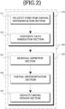
- FIG. 2 is a block diagram illustrating a configuration of an embodiment of the subsurface velocity model optimization software executed by the subsurface velocity model optimization apparatus according to the present invention.
- the subsurface velocity model optimization software 200 according to this embodiment includes a parameterization section 210 and a velocity model optimization section 220.
- the parameterization section 210 selects an initial velocity model of all exploration methods including exploration seismology and performs parameterization for the selected initial velocity model.
- the parameterization section 210 may include a velocity function partial differentiation section 211 and a synthetic data generation section 212.
- Equation 1 expresses a one-dimensional wave equation in the frequency domain.
- v denotes a velocity function
- Equation 1 is expressed as Equation 2.
- ⁇ 2 u ⁇ z 2 + s z ⁇ 2 u f z
- Each element (matrix coordinate) of a matrix of a 1D wave equation, a two-dimensional (2D) wave equation, or a three-dimensional (3D) wave equation may be expressed in the form of a straight line, a square, or a cuboid having an underground velocity.
- a velocity column of the matrix of the 1D wave equation may be expressed in the form of Fourier series, Fourier transform, cosine transform, sine transform, generalized Fourier series: Chebyshev polynomials, Hermitian polynomials, Laguerre polynomial, spherical harmonics function, spherical Bessel function, etc.
- Equation 3 expresses the velocity function v(z) of the 1D wave equation in the form of Fourier Transform.
- Equation 4 When the velocity function of Equation 3 is processed using a low pass filter (LPF), Equation 4 is obtained.
- Equation 5 When Equation 4 is taken partial derivative with respect to the Fourier coefficient a n , Equation 5 is obtained.
- Equation 7-1 a real part is expressed as Equation 7-1
- an imaginary part is expressed as Equation 7-2.
- the synthetic seismic data generation section 212 generates synthetic seismic data (virtual source field) from a partial differentiation result by the velocity function partial differentiation section 211.
- Equations 7-1 and 7-2 When the third term of Equations 7-1 and 7-2 is shifted to the right, Equations 8-1 and 8-2 are obtained.
- n -N, ...,0,1,2 ..., N, and f* denotes virtual earthquake data.
- the velocity model optimization section 220 apply Gauss Newton Method through waveform inversion for the velocity model parameterized by the parameterization section 210 to repeatedly update the velocity model, thereby optimizing the velocity model.
- the velocity model optimization section 220 may include a residual definition section 221, a partial differentiation section 222, and a velocity model update section 223.
- the residual definition section 221 defines a residual of the measured seismic data and the synthetic seismic data.
- the partial differentiation section 222 configured to take partial derivative the synthetic seismic data or the wavefield with respect to a coefficient of cosine transform or since transform or the complex Fourier series or the Fourier transform.
- the velocity model update section 223 configured to applying the Gauss Newton method to update the velocity model.
- the velocity model update section 223 may be implemented to optimize the velocity model by repeatedly updating the velocity model until the residual is minimized.
- the velocity model update section 223 may be implemented to optimize the velocity model by repeatedly updating the velocity model until the residual, that is, an error, is minimized using the Gauss-Newton Method (Pratt et al, 1988).
- the Gauss-Newton Method is a method of repeatedly solving a solution through the following Equations 12 and 13.
- Equations 12 and 13 p denotes a velocity model matrix element, H denotes an approximate Hessian matrix, E denotes a residual, which is an objective function, ⁇ p E denotes a gradient of the residual, which is the objective function, and J denotes a Jacobian matrix.
- the velocity model update section 223 may optimize the velocity model by repeatedly updating the velocity model until the residual is minimized using Equation 12 and Equation 13.
- Equation 14 is a 2D wave equation in the frequency domain, where N denotes a length of a horizontal distance of the velocity model, and M denotes a length of a vertical distance of the velocity model.
- Equation 15-1 a real part is expressed as Equation 15-1, and an imaginary part is expressed as Equation 15-2.
- Equation 17-1 a real part is expressed as Equation 17-1, and an imaginary part is expressed as Equation 17-2.
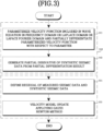
- FIG. 3 is a flowchart illustrating a configuration of an embodiment of a method of optimizing the subsurface velocity model according to the present invention.
- the subsurface velocity model optimization apparatus performs parameterization for all velocity models of exploration, including exploration seismology.
- the parameterization step 310 may include a velocity function partial differentiation step 311 and a synthetic seismic data generation step 312.
- the subsurface velocity model optimization apparatus parameterizes the velocity function included in the wave equation in the frequency domain or the Laplace domain or the Laplace Fourier domain and partially differentiates the parameterized velocity function with respect to a parameter.
- a description related thereto has been given using equations, and thus redundant description will be omitted.
- the subsurface velocity model optimization apparatus In the synthetic seismic data generation step 312, the subsurface velocity model optimization apparatus generates virtual earthquake data from a partial differentiation result by the partial differentiation of the velocity function step 311. A description related thereto has been given using equations, and thus redundant description will be omitted.
- the subsurface velocity model optimization apparatus derives a steepest descent direction or the Gauss Newton method through waveform inversion for the velocity model parameterized in the parameterization step 310 to repeatedly update the velocity model, thereby optimizing the velocity model.
- the velocity model optimization step 320 may include a residual definition step 321, a partial differentiation step 322, and a velocity model update step 323.
- the subsurface velocity model optimization apparatus defines a residual, a difference between the measured seismic data and the synthetic seismic data.
- a description related thereto has been given using equations, and thus redundant description will be omitted.
- the subsurface velocity model optimization apparatus partially differentiates the residual defined by the residual definition step 321 with respect to a coefficient of cosine transform or sine transform of the complex Fourier Series or the Fourier Transform.
- a description related thereto has been given using equations, and thus redundant description will be omitted.
- the velocity model is optimized by repeatedly updating the velocity model until the residual is minimized.
- implementation may be performed to optimize the velocity model by repeatedly updating the velocity model until the residual, that is, an error, is minimized using the Gauss-Newton Method.
- the present invention may optimize the velocity model of the exploration seismology, so that features or properties related to the underground stratum structure may be analyzed more accurately and efficiently.
- the present invention may be industrially used in the field of technology related to exploration seismology and application technology thereof.
Landscapes
- Engineering & Computer Science (AREA)
- Remote Sensing (AREA)
- Physics & Mathematics (AREA)
- Life Sciences & Earth Sciences (AREA)
- Acoustics & Sound (AREA)
- Environmental & Geological Engineering (AREA)
- Geology (AREA)
- General Life Sciences & Earth Sciences (AREA)
- General Physics & Mathematics (AREA)
- Geophysics (AREA)
- Geophysics And Detection Of Objects (AREA)
Abstract
Description
- The present invention relates to seismic exploration technology, and more particularly to an apparatus and method for obtaining a subsurface velocity model.
- The exploration seismology using FWI(Full Waveform Inversion) is a technique that increases a probability of finding a geological location where subsurface energy resources such as oil and natural gas are buried. In exploration seismology, a subsurface stratum structure is determined through intensive computations using seismic data, and the underground stratum structure is analyzed and visualized using a velocity model to evaluate the location and reserves of the subsurface energy resources.
- To accurately analyze the underground stratum structure using FWI, the velocity model needs to be repeatedly updated to minimize an objective function (residual), which is defined as a difference between measured data by manmade seismic sources and synthetic data (synthesized from computer modeling of wave equations).
- In a FWI of the exploration seismology, a good initial velocity model is crucial to both reduce the number of iterations for high resolution inversion of the seismic data and guarantee the convergence to the true velocity model.
- The present inventor has conducted research on subsurface velocity model imaging technology that may obtain the velocity model by applying a Gauss Newton method through a spectral parameterization of the velocity model in exploration seismology.
- Patent Document: Republic of
Korea Patent No. 10-2026063 (announced on September 27, 2019 - An object of the present invention is to provide an apparatus and method for obtaining a subsurface velocity model by applying a Gauss Newton method through a spectral parameterization of the velocity model in exploration seismology.
- In accordance with an aspect of the present invention, the above and other objects can be accomplished by the provision of an apparatus for obtaining an good initial subsurface velocity model including a nonvolatile memory configured to store execution code for obtaining the good initial velocity model software, a processor configured to execute the execution code for obtaining the good initial subsurface velocity model software stored in the nonvolatile memory, a display configured to display a software for obtaining the initial subsurface velocity model output by the execution code for the technique obtaining the good initial subsurface velocity model software executed by the processor, and a user input unit configured to receive user operation for input and output of the software of obtaining the good initial subsurface velocity model, wherein a finding of good initial subsurface velocity model software includes a parameterization section configured to parametrize a velocity model, and a velocity model optimization section configured to applying a Gauss Newton method through waveform inversion for the velocity model parameterized by the parameterization section to repeatedly update the velocity model, thereby obtaining the good initial subsurface velocity model.
- The parameterization section may include a partial differentiation of the subsurface velocity model configured to parameterize a velocity function included in a wave equation in a frequency domain or the Laplace domain or the Laplace Fourier domain and to take partial derivative of the subsurface velocity function with respect to a parameter, and a synthetic seismic data generation section configured to generate synthetic seismic data from a partial differentiation result by the partial differentiation section of the subsurface velocity function.
- The velocity model optimization section may include a residual definition section configured to define a residual between the measured seismic data and the synthetic seismic data, a partial differentiation section configured to partially differentiate the synthetic seismic data with respect to a coefficient of cosine transform, sine transform or complex Fourier series or Fourier transform and a velocity model update section configured to apply the Gauss Newton method and to update the velocity model.
- The velocity model update section may find the good initial velocity model by repeatedly updating the velocity model until the residual is minimized.
- In accordance with another aspect of the present invention, there is provided a method of optimizing a subsurface velocity model including parameterizing a velocity model in exploration seismology, and using Gauss Newton method through waveform inversion for the velocity model parameterized by the parameterizing to repeatedly update the velocity model, thereby optimizing the good initial velocity model.
- The parameterizing may include parameterizing a velocity function included in a wave function in a frequency domain or a Laplace domain or a Laplace Fourier domain and taking partial derivative of the parameterized velocity function with respect to a parameter, and generating synthetic seismic data from a partial differentiation result by the parameterizing a velocity function.
- The Gauss Newton method may include defining a partial derivative of the synthetic seismic data and the synthetic seismic data, taking partial derivative of the synthetic seismic data with respect to a coefficient of cosine transform, since transform or the complex Fourier series or the Fourier transform. then applying the Gauss Newton method, and updating the velocity model.
- The Gauss Newton method include optimizing the velocity model by repeatedly updating the velocity model until the residual is minimized.
- The above and other objects, features and other advantages of the present invention will be more clearly understood from the following detailed description taken in conjunction with the accompanying drawings, in which:
-
FIG. 1 is a block diagram illustrating a configuration of an embodiment of a subsurface velocity model optimization apparatus according to the present invention; -
FIG. 2 is a block diagram illustrating a configuration of an embodiment of subsurface velocity model optimization software executed by the subsurface velocity model optimization apparatus according to the present invention; and -
FIG. 3 is a flowchart illustrating a configuration of an embodiment of a method of optimizing the subsurface velocity model according to the present invention. - Hereinafter, the present invention will be described in detail through preferred embodiments described with reference to the attached drawings so that those skilled in the art may easily understand and reproduce the embodiments. Even though specific embodiments are illustrated in the drawings and related detailed descriptions are given, the specific embodiments are not intended to limit various embodiments of the present invention to any particular form.
- In describing the present invention, when it is determined that a detailed description of a related known function or configuration may unnecessarily obscure the gist of the embodiments of the present invention, the detailed description will be omitted.
- When a component is mentioned as being "coupled" or "connected" to another component, it is understood that the component may be directly coupled or connected to another component, and still another component may be present therebetween.
- On the other hand, when a component is mentioned as being "directly coupled" or "directly connected" to another component, it should be understood that there are no other components therebetween.
-
FIG. 1 is a block diagram illustrating a configuration of an embodiment of a subsurface velocity model optimization apparatus according to the present invention. As illustrated inFIG. 1 , a subsurface velocitymodel optimization apparatus 100 according to this embodiment includes anonvolatile memory 110, aprocessor 120, adisplay 130, and auser input unit 140. - The
nonvolatile memory 110 stores execution code for subsurface velocitymodel optimization software 200. For example, thenonvolatile memory 110 may be a flash memory, an EEPROM, etc. - The
processor 120 executes the execution code for the subsurface velocitymodel optimization software 200 stored in thenonvolatile memory 110. In this instance, theprocessor 120 may be a single core processor or a multicore processor. - The
display 130 displays a subsurface velocity model optimization software screen output by the execution code for the subsurface velocitymodel optimization software 200 executed by theprocessor 120. For example, thedisplay 130 may be an LED, an OLED, etc. However, thedisplay 130 is not limited thereto. - The
user input unit 140 receives user operations for input and output of the subsurface velocitymodel optimization software 200. For example, theuser input unit 140 may be a keyboard, a mouse, a touch panel, etc. However, theuser input unit 140 is not limited thereto. -
FIG. 2 is a block diagram illustrating a configuration of an embodiment of the subsurface velocity model optimization software executed by the subsurface velocity model optimization apparatus according to the present invention. As illustrated inFIG. 2 , the subsurface velocitymodel optimization software 200 according to this embodiment includes aparameterization section 210 and a velocitymodel optimization section 220. - The
parameterization section 210 selects an initial velocity model of all exploration methods including exploration seismology and performs parameterization for the selected initial velocity model. In this instance, theparameterization section 210 may include a velocity functionpartial differentiation section 211 and a syntheticdata generation section 212. - The velocity function
partial differentiation section 211 parameterizes a velocity function included in a wave equation in the frequency domain or the Laplace domain or the Laplace Fourier domain and take partial derivative the parameterized velocity function with respect to a parameter.
- Equation 1 expresses a one-dimensional wave equation in the frequency domain. In Equation 1, v denotes a velocity function, and when the reciprocal of the square of the velocity function is set to s(z), Equation 1 is expressed as Equation 2.

- Each element (matrix coordinate) of a matrix of a 1D wave equation, a two-dimensional (2D) wave equation, or a three-dimensional (3D) wave equation may be expressed in the form of a straight line, a square, or a cuboid having an underground velocity.
- A velocity column of the matrix of the 1D wave equation may be expressed in the form of Fourier series, Fourier transform, cosine transform, sine transform, generalized Fourier series: Chebyshev polynomials, Hermitian polynomials, Laguerre polynomial, spherical harmonics function, spherical Bessel function, etc.
- Equation 3 expresses the velocity function v(z) of the 1D wave equation in the form of Fourier Transform.

- Equation 3 means that a value of a partial derivative of a wave field (Synthetic seismic data) may be obtained by parameterizing a Fourier coefficient an of the velocity function as ai, i = -∞, ..., ∞.
- When the velocity function of Equation 3 is processed using a low pass filter (LPF), Equation 4 is obtained.

- When Equation 4 is taken partial derivative with respect to the Fourier coefficient an, Equation 5 is obtained.

- When Equation 5 is substituted into Equation 1, Equation 6 is obtained.

- When Equation 6 is taken partial derivative with respect to the Fourier coefficient an, a real part is expressed as Equation 7-1, and an imaginary part is expressed as Equation 7-2.

- In Equation 7-1,


- In Equation 7-2,

- The synthetic seismic
data generation section 212 generates synthetic seismic data (virtual source field) from a partial differentiation result by the velocity functionpartial differentiation section 211. - When the third term of Equations 7-1 and 7-2 is shifted to the right, Equations 8-1 and 8-2 are obtained.

- In Equation 8-1, n = -N, ...,0,1,2 ..., N, and f* denotes virtual earthquake data.

- In Equation 8-2, n = -N, ...,0,1,2 ..., N, and f* denotes virtual earthquake data.
- The velocity
model optimization section 220 apply Gauss Newton Method through waveform inversion for the velocity model parameterized by theparameterization section 210 to repeatedly update the velocity model, thereby optimizing the velocity model. In this instance, the velocitymodel optimization section 220 may include aresidual definition section 221, apartial differentiation section 222, and a velocitymodel update section 223. - The
residual definition section 221 defines a residual of the measured seismic data and the synthetic seismic data. - The
partial differentiation section 222 configured to take partial derivative the synthetic seismic data or the wavefield with respect to a coefficient of cosine transform or since transform or the complex Fourier series or the Fourier transform. - The velocity
model update section 223 configured to applying the Gauss Newton method to update the velocity model. In this instance, the velocitymodel update section 223 may be implemented to optimize the velocity model by repeatedly updating the velocity model until the residual is minimized. - For example, the velocity
model update section 223 may be implemented to optimize the velocity model by repeatedly updating the velocity model until the residual, that is, an error, is minimized using the Gauss-Newton Method (Pratt et al, 1988). The Gauss-Newton Method is a method of repeatedly solving a solution through the following Equations 12 and 13.

- In Equations 12 and 13, p denotes a velocity model matrix element, H denotes an approximate Hessian matrix, E denotes a residual, which is an objective function, ∇ pE denotes a gradient of the residual, which is the objective function, and J denotes a Jacobian matrix.
- The velocity
model update section 223 may optimize the velocity model by repeatedly updating the velocity model until the residual is minimized using Equation 12 and Equation 13. - The 1D wave equation has been described above as an example. However, a 2D wave equation may be applied as follows.

- Equation 14 is a 2D wave equation in the frequency domain, where N denotes a length of a horizontal distance of the velocity model, and M denotes a length of a vertical distance of the velocity model.
- When Equation 14 is partially differentiated with respect to a 2D Fourier coefficient as in the case of the 1D wave equation described above, a real part is expressed as Equation 15-1, and an imaginary part is expressed as Equation 15-2.


- In Equations 15-1 and 15-2, n = -N, ...,0, ..., N, m = -M, ...,0, ... M .
- Meanwhile, a 3D wave equation may be applied as follows.

- When Equation 16 is taken partial derivate with respect to a 3D Fourier coefficient as in the case of the 1D wave equation described above, a real part is expressed as Equation 17-1, and an imaginary part is expressed as Equation 17-2.
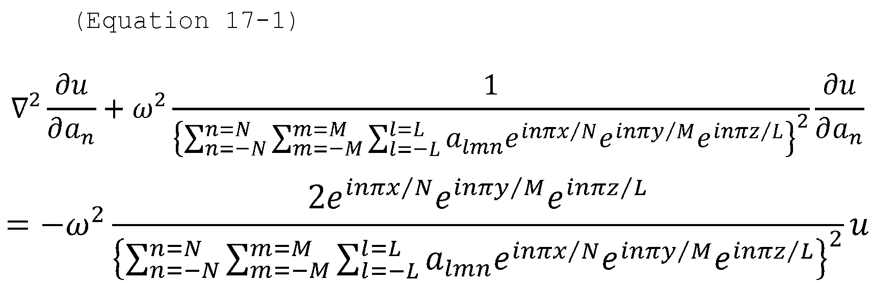

- In Equations 17-1 and 17-2, n = -N, ...,0,1, ...N , m = -M, ... ,0, ... M, l = -L, ...,0, ... L .
- A subsurface velocity model optimization operation of the subsurface velocity model optimization apparatus according to the present invention described above will be described through
FIG. 3. FIG. 3 is a flowchart illustrating a configuration of an embodiment of a method of optimizing the subsurface velocity model according to the present invention. - First, in a
parameterization step 310, the subsurface velocity model optimization apparatus performs parameterization for all velocity models of exploration, including exploration seismology. In this instance, theparameterization step 310 may include a velocity functionpartial differentiation step 311 and a synthetic seismicdata generation step 312. - In the
partial differentiation step 311, the subsurface velocity model optimization apparatus parameterizes the velocity function included in the wave equation in the frequency domain or the Laplace domain or the Laplace Fourier domain and partially differentiates the parameterized velocity function with respect to a parameter. A description related thereto has been given using equations, and thus redundant description will be omitted. - In the synthetic seismic
data generation step 312, the subsurface velocity model optimization apparatus generates virtual earthquake data from a partial differentiation result by the partial differentiation of thevelocity function step 311. A description related thereto has been given using equations, and thus redundant description will be omitted. - Next, in the velocity model optimization step 320, the subsurface velocity model optimization apparatus derives a steepest descent direction or the Gauss Newton method through waveform inversion for the velocity model parameterized in the
parameterization step 310 to repeatedly update the velocity model, thereby optimizing the velocity model. In this instance, the velocity model optimization step 320 may include aresidual definition step 321, a partial differentiation step 322, and a velocity model update step 323. - In the
residual definition step 321, the subsurface velocity model optimization apparatus defines a residual, a difference between the measured seismic data and the synthetic seismic data. A description related thereto has been given using equations, and thus redundant description will be omitted. - In the partial differentiation step 322, the subsurface velocity model optimization apparatus partially differentiates the residual defined by the
residual definition step 321 with respect to a coefficient of cosine transform or sine transform of the complex Fourier Series or the Fourier Transform. A description related thereto has been given using equations, and thus redundant description will be omitted. - In this instance, in the velocity model update step 323, the velocity model is optimized by repeatedly updating the velocity model until the residual is minimized.
- For example, in the velocity model update step 323, implementation may be performed to optimize the velocity model by repeatedly updating the velocity model until the residual, that is, an error, is minimized using the Gauss-Newton Method.
- By this implementation, the present invention may optimize the velocity model of the exploration seismology, so that features or properties related to the underground stratum structure may be analyzed more accurately and efficiently.
- The various embodiments disclosed in this specification and drawings are merely presented as specific examples to aid understanding, and are not intended to limit the scope of the various embodiments of the present invention.
- Accordingly, the scope of the various embodiments of the present invention should be interpreted as including all changed or modified forms derived based on the technical idea of the various embodiments of the present invention in addition to the embodiments described herein.
- The present invention may be industrially used in the field of technology related to exploration seismology and application technology thereof.
Claims (8)
- An apparatus for optimizing a subsurface velocity model, the apparatus comprising:a nonvolatile memory configured to store execution code for subsurface velocity model optimization software;a processor configured to execute the execution code for the subsurface velocity model optimization software stored in the nonvolatile memory;a display configured to display a subsurface velocity model optimization software screen output by the execution code for the subsurface velocity model optimization software executed by the processor; anda user input unit configured to receive user operation for input and output of the subsurface velocity model optimization software,wherein the subsurface velocity model optimization software comprises:a parameterization section configured to parametrize a velocity model; anda velocity model optimization section configured to applying a Gauss Newton method through waveform inversion for the velocity model parameterized by the parameterization section to repeatedly update the velocity model, thereby obtaining the good initial subsurface velocity model.
- The apparatus according to claim 1, wherein the parameterization section comprises:the partial differentiation of a velocity function section configured to parameterize a velocity function included in a wave equation in a frequency domain or the Laplace domain or the Laplace Fourier domain to take partial derivative the parameterized velocity function with respect to a parameter; anda synthetic data generation section configured to generate synthetic seismic data from a partial differentiation result by of the partial differentiation of the velocity function section.
- The apparatus according to claim 2, wherein the velocity model optimization section comprises:a residual definition section configured to define a residual of measured seismic data and the synthetic seismic data;a partial differentiation section configured to take partial derivative the synthetic seismic data or the wavefield with respect to a coefficient of cosine transform or since transform or the complex Fourier series or the Fourier transform ; anda velocity model update section configured to applying the Gauss Newton method to update the velocity model.
- The apparatus according to claim 3, wherein the velocity model update section optimizes the velocity model by repeatedly updating the velocity model until the residual is minimized.
- A method of optimizing a subsurface velocity model, the method comprising:parameterizing a velocity model; andvelocity model optimizing configured to applying a Gauss Newton method through waveform inversion for the velocity model parameterized by the parameterizing to repeatedly update the velocity model, thereby optimizing the velocity model.
- The method according to claim 5, wherein the parameterizing comprises:parameterizing a velocity function included in a wave function in a frequency domain or a Laplace or a Laplace Fourier domain, and taking partial derivative of the parameterized velocity function with respect to a parameter; and generating the synthetic seismic data from a partial differentiation result by the parameterizing a velocity function.
- The method according to claim 6, wherein the velocity model optimizing comprises:defining a residual of the measured seismic data and the synthetic seismic data;partial differentiating which takes partial derivative the synthetic seismic data or the wavefield with respect to a coefficient of cosine transform or since transform or the complex Fourier series or the Fourier transform ; anda velocity model updating which apply the Gauss Newton method and update the velocity model.
- The method according to claim 7, wherein the Gauss Newton method comprises optimizing the velocity model by repeatedly updating the velocity model until the residual is minimized.
Applications Claiming Priority (2)
| Application Number | Priority Date | Filing Date | Title |
|---|---|---|---|
| US202363466990P | 2023-05-16 | 2023-05-16 | |
| KR1020240026259A KR20240165849A (en) | 2023-05-16 | 2024-02-23 | Optimization apparatus and method for subsurface velocity model |
Publications (2)
| Publication Number | Publication Date |
|---|---|
| EP4465095A1 true EP4465095A1 (en) | 2024-11-20 |
| EP4465095B1 EP4465095B1 (en) | 2026-03-04 |
Family
ID=90721260
Family Applications (1)
| Application Number | Title | Priority Date | Filing Date |
|---|---|---|---|
| EP24169665.7A Active EP4465095B1 (en) | 2023-05-16 | 2024-04-11 | Apparatus and method for optimizing subsurface velocity model |
Country Status (3)
| Country | Link |
|---|---|
| US (1) | US20240385342A1 (en) |
| EP (1) | EP4465095B1 (en) |
| KR (1) | KR20240165862A (en) |
Citations (2)
| Publication number | Priority date | Publication date | Assignee | Title |
|---|---|---|---|---|
| US20090006000A1 (en) * | 2007-06-26 | 2009-01-01 | Changsoo Shin | Method for velocity analysis using waveform inversion in laplace domain for geophysical imaging |
| KR102026063B1 (en) | 2018-05-14 | 2019-09-27 | 서울대학교 산학협력단 | A robust seismic imaging method using iterative full waveform inversion |
-
2024
- 2024-04-03 US US18/626,303 patent/US20240385342A1/en active Pending
- 2024-04-11 EP EP24169665.7A patent/EP4465095B1/en active Active
- 2024-04-18 KR KR1020240051834A patent/KR20240165862A/en active Pending
Patent Citations (2)
| Publication number | Priority date | Publication date | Assignee | Title |
|---|---|---|---|---|
| US20090006000A1 (en) * | 2007-06-26 | 2009-01-01 | Changsoo Shin | Method for velocity analysis using waveform inversion in laplace domain for geophysical imaging |
| KR102026063B1 (en) | 2018-05-14 | 2019-09-27 | 서울대학교 산학협력단 | A robust seismic imaging method using iterative full waveform inversion |
Non-Patent Citations (2)
| Title |
|---|
| GAO FENGXIA ET AL: "3-D Seismic Inversion by Model Parameterization With Fourier Coefficients", vol. 61, 1 January 2023 (2023-01-01), USA, pages 1 - 16, XP093204001, ISSN: 0196-2892, Retrieved from the Internet <URL:https://ieeexplore.ieee.org/stampPDF/getPDF.jsp?tp=&arnumber=10105640&ref=aHR0cHM6Ly9pZWVleHBsb3JlLmllZWUub3JnL2Fic3RyYWN0L2RvY3VtZW50LzEwMTA1NjQw> [retrieved on 20240911], DOI: 10.1109/TGRS.2023.3268410 * |
| LEE DAWOON ET AL: "Elastic Full-Waveform Inversion Using Both the Multiparametric Approximate Hessian and the Discrete Cosine Transform", IEEE TRANSACTIONS ON GEOSCIENCE AND REMOTE SENSING, vol. 60, 9 August 2021 (2021-08-09), USA, pages 1 - 10, XP093203995, ISSN: 0196-2892, DOI: 10.1109/TGRS.2021.3101193 * |
Also Published As
| Publication number | Publication date |
|---|---|
| KR20240165862A (en) | 2024-11-25 |
| EP4465095B1 (en) | 2026-03-04 |
| US20240385342A1 (en) | 2024-11-21 |
Similar Documents
| Publication | Publication Date | Title |
|---|---|---|
| EP3063562B1 (en) | Methods of subsurface exploration, computer program product and computer-readable storage medium | |
| US9075159B2 (en) | System and method for seismic data inversion | |
| CN113740901B (en) | Land seismic data full-waveform inversion method and device based on complex undulating surface | |
| US11428835B2 (en) | Facilitating hydrocarbon exploration and extraction by applying a machine-learning model to seismic data | |
| WO2012170201A2 (en) | System and method for seismic data inversion by non-linear model update | |
| CN103329009A (en) | System and method for data inversion with phase unwrapping | |
| EP2975437A1 (en) | Method and system to invert for fault activity and tectonic stress | |
| US20120316790A1 (en) | System and method for data inversion with phase extrapolation | |
| Di et al. | A new algorithm for evaluating 3D curvature and curvature gradient for improved fracture detection | |
| EP2803043B1 (en) | 3-d surface-based waveform inversion | |
| Qu et al. | Elastic full-waveform inversion for surface topography | |
| Lambrecht et al. | A nodal discontinuous Galerkin approach to 3-D viscoelastic wave propagation in complex geological media | |
| CN106291677A (en) | A kind of poststack sound impedance inversion method based on match tracing method | |
| Willemsen et al. | An efficient coupled acoustic-elastic local solver applied to phase inversion | |
| US9928315B2 (en) | Re-ordered interpolation and convolution for faster staggered-grid processing | |
| Abolhassani et al. | Efficient preconditioned least-squares wave-equation migration | |
| US20240385342A1 (en) | Apparatus and method for optimizing subsurface velocity model | |
| Alkhalifah et al. | An eikonal-based formulation for traveltime perturbation with respect to the source location | |
| Raknes et al. | Challenges and solutions for performing 3D time-domain elastic full-waveform inversion | |
| Jaimes-Osorio et al. | Reduced memory implementation of a local elastic finite-difference solver | |
| Fu et al. | Multiscale modeling of acoustic wave propagation in 2D heterogeneous media using local spectral basis functions | |
| CN120522806A (en) | Three-dimensional seismic exploration method and system based on multi-source geological data fusion | |
| Chu et al. | Efficient 3D frequency response modeling with spectral accuracy by the rapid expansion method | |
| CA3106006C (en) | Facilitating hydrocarbon exploration and extraction by applying a machine-learning model to seismic data | |
| KR20240165849A (en) | Optimization apparatus and method for subsurface velocity model |
Legal Events
| Date | Code | Title | Description |
|---|---|---|---|
| PUAI | Public reference made under article 153(3) epc to a published international application that has entered the european phase |
Free format text: ORIGINAL CODE: 0009012 |
|
| STAA | Information on the status of an ep patent application or granted ep patent |
Free format text: STATUS: REQUEST FOR EXAMINATION WAS MADE |
|
| 17P | Request for examination filed |
Effective date: 20240411 |
|
| AK | Designated contracting states |
Kind code of ref document: A1 Designated state(s): AL AT BE BG CH CY CZ DE DK EE ES FI FR GB GR HR HU IE IS IT LI LT LU LV MC ME MK MT NL NO PL PT RO RS SE SI SK SM TR |
|
| GRAP | Despatch of communication of intention to grant a patent |
Free format text: ORIGINAL CODE: EPIDOSNIGR1 |
|
| STAA | Information on the status of an ep patent application or granted ep patent |
Free format text: STATUS: GRANT OF PATENT IS INTENDED |
|
| INTG | Intention to grant announced |
Effective date: 20251014 |
|
| P01 | Opt-out of the competence of the unified patent court (upc) registered |
Free format text: CASE NUMBER: UPC_APP_0013821_4465095/2025 Effective date: 20251119 |
|
| GRAS | Grant fee paid |
Free format text: ORIGINAL CODE: EPIDOSNIGR3 |
|
| GRAA | (expected) grant |
Free format text: ORIGINAL CODE: 0009210 |
|
| STAA | Information on the status of an ep patent application or granted ep patent |
Free format text: STATUS: THE PATENT HAS BEEN GRANTED |
|
| AK | Designated contracting states |
Kind code of ref document: B1 Designated state(s): AL AT BE BG CH CY CZ DE DK EE ES FI FR GB GR HR HU IE IS IT LI LT LU LV MC ME MK MT NL NO PL PT RO RS SE SI SK SM TR |
|
| REG | Reference to a national code |
Ref country code: CH Ref legal event code: F10 Free format text: ST27 STATUS EVENT CODE: U-0-0-F10-F00 (AS PROVIDED BY THE NATIONAL OFFICE) Effective date: 20260304 Ref country code: GB Ref legal event code: FG4D |
|
| REG | Reference to a national code |
Ref country code: DE Ref legal event code: R096 Ref document number: 602024002911 Country of ref document: DE |
|
| REG | Reference to a national code |
Ref country code: IE Ref legal event code: FG4D |