EP4465075A1 - Radar emulator and method of testing a radar sensor - Google Patents
Radar emulator and method of testing a radar sensor Download PDFInfo
- Publication number
- EP4465075A1 EP4465075A1 EP24164943.3A EP24164943A EP4465075A1 EP 4465075 A1 EP4465075 A1 EP 4465075A1 EP 24164943 A EP24164943 A EP 24164943A EP 4465075 A1 EP4465075 A1 EP 4465075A1
- Authority
- EP
- European Patent Office
- Prior art keywords
- signal
- radar
- interference
- interference signal
- emulator
- Prior art date
- Legal status (The legal status is an assumption and is not a legal conclusion. Google has not performed a legal analysis and makes no representation as to the accuracy of the status listed.)
- Pending
Links
Images
Classifications
-
- G—PHYSICS
- G01—MEASURING; TESTING
- G01S—RADIO DIRECTION-FINDING; RADIO NAVIGATION; DETERMINING DISTANCE OR VELOCITY BY USE OF RADIO WAVES; LOCATING OR PRESENCE-DETECTING BY USE OF THE REFLECTION OR RERADIATION OF RADIO WAVES; ANALOGOUS ARRANGEMENTS USING OTHER WAVES
- G01S7/00—Details of systems according to groups G01S13/00, G01S15/00, G01S17/00
- G01S7/02—Details of systems according to groups G01S13/00, G01S15/00, G01S17/00 of systems according to group G01S13/00
- G01S7/40—Means for monitoring or calibrating
- G01S7/4004—Means for monitoring or calibrating of parts of a radar system
-
- G—PHYSICS
- G01—MEASURING; TESTING
- G01S—RADIO DIRECTION-FINDING; RADIO NAVIGATION; DETERMINING DISTANCE OR VELOCITY BY USE OF RADIO WAVES; LOCATING OR PRESENCE-DETECTING BY USE OF THE REFLECTION OR RERADIATION OF RADIO WAVES; ANALOGOUS ARRANGEMENTS USING OTHER WAVES
- G01S7/00—Details of systems according to groups G01S13/00, G01S15/00, G01S17/00
- G01S7/02—Details of systems according to groups G01S13/00, G01S15/00, G01S17/00 of systems according to group G01S13/00
- G01S7/40—Means for monitoring or calibrating
- G01S7/4052—Means for monitoring or calibrating by simulation of echoes
- G01S7/4056—Means for monitoring or calibrating by simulation of echoes specially adapted to FMCW
-
- G—PHYSICS
- G01—MEASURING; TESTING
- G01S—RADIO DIRECTION-FINDING; RADIO NAVIGATION; DETERMINING DISTANCE OR VELOCITY BY USE OF RADIO WAVES; LOCATING OR PRESENCE-DETECTING BY USE OF THE REFLECTION OR RERADIATION OF RADIO WAVES; ANALOGOUS ARRANGEMENTS USING OTHER WAVES
- G01S7/00—Details of systems according to groups G01S13/00, G01S15/00, G01S17/00
- G01S7/02—Details of systems according to groups G01S13/00, G01S15/00, G01S17/00 of systems according to group G01S13/00
- G01S7/40—Means for monitoring or calibrating
-
- G—PHYSICS
- G01—MEASURING; TESTING
- G01S—RADIO DIRECTION-FINDING; RADIO NAVIGATION; DETERMINING DISTANCE OR VELOCITY BY USE OF RADIO WAVES; LOCATING OR PRESENCE-DETECTING BY USE OF THE REFLECTION OR RERADIATION OF RADIO WAVES; ANALOGOUS ARRANGEMENTS USING OTHER WAVES
- G01S7/00—Details of systems according to groups G01S13/00, G01S15/00, G01S17/00
- G01S7/02—Details of systems according to groups G01S13/00, G01S15/00, G01S17/00 of systems according to group G01S13/00
- G01S7/40—Means for monitoring or calibrating
- G01S7/4052—Means for monitoring or calibrating by simulation of echoes
- G01S7/406—Means for monitoring or calibrating by simulation of echoes using internally generated reference signals, e.g. via delay line, via RF or IF signal injection or via integrated reference reflector or transponder
-
- G—PHYSICS
- G01—MEASURING; TESTING
- G01S—RADIO DIRECTION-FINDING; RADIO NAVIGATION; DETERMINING DISTANCE OR VELOCITY BY USE OF RADIO WAVES; LOCATING OR PRESENCE-DETECTING BY USE OF THE REFLECTION OR RERADIATION OF RADIO WAVES; ANALOGOUS ARRANGEMENTS USING OTHER WAVES
- G01S7/00—Details of systems according to groups G01S13/00, G01S15/00, G01S17/00
- G01S7/02—Details of systems according to groups G01S13/00, G01S15/00, G01S17/00 of systems according to group G01S13/00
- G01S7/40—Means for monitoring or calibrating
- G01S7/4052—Means for monitoring or calibrating by simulation of echoes
- G01S7/4082—Means for monitoring or calibrating by simulation of echoes using externally generated reference signals, e.g. via remote reflector or transponder
-
- G—PHYSICS
- G01—MEASURING; TESTING
- G01S—RADIO DIRECTION-FINDING; RADIO NAVIGATION; DETERMINING DISTANCE OR VELOCITY BY USE OF RADIO WAVES; LOCATING OR PRESENCE-DETECTING BY USE OF THE REFLECTION OR RERADIATION OF RADIO WAVES; ANALOGOUS ARRANGEMENTS USING OTHER WAVES
- G01S7/00—Details of systems according to groups G01S13/00, G01S15/00, G01S17/00
- G01S7/02—Details of systems according to groups G01S13/00, G01S15/00, G01S17/00 of systems according to group G01S13/00
- G01S7/40—Means for monitoring or calibrating
- G01S7/4052—Means for monitoring or calibrating by simulation of echoes
- G01S7/4082—Means for monitoring or calibrating by simulation of echoes using externally generated reference signals, e.g. via remote reflector or transponder
- G01S7/4086—Means for monitoring or calibrating by simulation of echoes using externally generated reference signals, e.g. via remote reflector or transponder in a calibrating environment, e.g. anechoic chamber
Definitions
- the invention relates to a radar emulator for testing a radar sensor. Further, the invention relates to a method of testing a radar sensor.
- radar sensors are used in different applications, for instance in vehicles.
- the number of radar sensors used in vehicles has increased significantly in the recent years due to different modern functionalities provided by the vehicles, for instance autonomous parking or even autonomous driving.
- the radar sensors are used to sense the surrounding of the vehicle, thereby ensuring that the vehicle can be parked or even driven in an autonomous manner.
- these different signals may relate to interference signals that have been transmitted by other radar sensors, for instance radar sensors of the same vehicle, radar sensors of other traffic participants or radar stations associated with infrastructure, e.g. V2X stations.
- the invention provides a radar emulator for testing a radar sensor.
- the radar emulator comprises a radar signal receiver capable of receiving a radar signal having at least one characteristic.
- the radar emulator also comprises a radar signal processor capable of processing the radar signal received.
- the radar emulator has a response signal generator capable of generating a response signal to the radar signal received.
- the radar emulator comprises an interference signal generator capable of generating an interference signal that is synchronized with the response signal in time.
- the radar emulator has an adder capable of combining the interference signal and the response signal in order to obtain a combined output signal that comprises the response signal generated and the interference signal generated.
- the invention provides a method of testing a radar sensor.
- the method comprises the following steps:
- a single device namely the radar emulator, that comprises the response signal generator as well as the interference signal generator.
- the generators are connected with each other by the adder that combines the signals generated in order to provide the combined output signal.
- the combined output signal can be output by the radar emulator via an output interface.
- the radar emulator may comprise at least one antenna that is connected with the output interface such that the combined output signal is output via the at least one antenna as a radio signal, namely a radar signal.
- the adder can combine the signals generated since they are synchronized with each other in time. This can be achieved easily and in a cost-efficient manner, as both the response signal generator and the interference signal generator are integrated within a single device.
- the single device namely the radar emulator, encompasses the response signal generator as well as the interference signal generator.
- the single device namely the radar (target) emulator, also ensures that a single output signal is output that comprises the response signal as well as the interference signal.
- the complexity of the testing setup can be reduced significantly, as only one device is used for providing the response signal and the interference signal simultaneously.
- the interference signal generator also called an interference source
- the response signal generator also called a target simulator
- the response signal generator is capable of generating the response signal based on the at least one characteristic of the radar signal.
- the response signal may be generated based on the at least one characteristic of the radar signal.
- the radar signal received may be analyzed by the radar signal processor in order to determine the at least one characteristic of the radar signal based on which the response signal is generated. This ensures that the response signal matches to the radar signal received. Accordingly, a target can be simulated for the radar sensor to be tested.
- the response signal generator is an echo generator, as it is configured to generate an echo signal with regard to the radar signal output by the radar sensor to be tested.
- the interference signal generator is configured to generate the interference signal based on the at least one characteristic of the radar signal.
- the interference signal may be generated based on the at least one characteristic of the radar signal.
- the radar signal received may be analyzed by the radar signal processor in order to determine the at least one characteristic of the radar signal based on which the interference signal is generated. This ensures that the interference signal matches to the radar signal received. Accordingly, an interferer can be simulated for the radar sensor to be tested.
- the interference signal generator is an interference source, as it is configured to generate an interfering signal with regard to the radar signal output by the radar sensor to be tested.
- the response signal generator and/or the interference signal generator may be controlled by means of the radar signal processor that has determined the at least one characteristic of the radar signal received previously.
- a certain scenario can be applied for testing the radar sensor to be tested, as the response signal and/or the interference signal are/is adapted to the radar signal received, namely the at least one characteristic of the radar signal received, which was determined by the radar signal processor.
- the radar signal received may be analyzed by the radar signal processor, allowing to directly synchronize the interference signal and the response signal.
- the operation of the interference signal generator and the operation of the response signal generator are synchronized with reach other based on the analysis of the radar signal received.
- the at least one characteristic is a ramp of a frequency modulated continuous wave (FMCW) radar signal, a timing information of the radar signal and/or a frequency range of the radar signal.
- the respective characteristic may be determined by the radar signal processor when processing/analyzing the radar signal received. Particularly, a slope of the ramp of the frequency modulated continuous wave (FMCW) radar signal is determined.
- the at least one characteristic determined may be used for generating the response signal and/or the interference signal appropriately.
- a predefined waveform may be used for generating the interference signal.
- the radar signal processor may comprise an estimation circuit that is capable of estimating the at least one characteristic when processing the radar signal received.
- the radar signal processor does not absolutely determine the at least one characteristic of the radar signal received, but estimates the at least one characteristic based on information obtained when processing the radar signal received. This reduces the efforts required for obtaining the at least one characteristic.
- the radar signal processor is a real-time processor that is capable of determining the at least one characteristic in real time.
- fast processing of the radar signal received is ensured due to the real-time processor. Accordingly, a delay in processing the radar signal received can be minimized.
- the real-time processor is capable of adapting a setting of a response signal generator and/or a setting of the interference signal generator in real time. Accordingly, a delay in generating the response signal and/or the interference signal can be minimized as well.
- the interference signal may be inverted in frequency domain (slope of the ramp for FMCW), within the frequency range of interest and/or time of interest.
- an interference signal shall be generated as soon as possible, which can be ensured by the real-time processor.
- the adder is a digital adder that is capable of processing the interference signal and the response signal in a digital manner in order to obtain a digital combined output signal.
- the digital combined output signal is converted afterwards into in analog combined output signal that is forwarded to the output interface of the radar emulator in order to be transmitted via the at least one antenna connected to the output interface.
- the digital processing ensures that the interference signal generated and the response signal generated can be synchronized in time in an efficient manner.
- the adder is an analog adder that is capable of processing the interference signal and the response signal in an analog manner in order to obtain an analog combined output signal.
- the adder may be directly connected, e.g. via a signal line, to the output interface.
- no digital to analog conversion (DAC) is necessary prior to outputting the analog combined output signal via the at least one antenna.
- DAC digital to analog conversion
- the processing of the interference signal generated and the response signal generated in an analog manner is more complex with regard to the time synchronization of the respective signals generated.
- the radar emulator comprises a user interface that is connected with the interference signal generator such that the user is enabled to set the interference signal generator via the user interface.
- the user may define certain parameters of the interference signal to be used for testing the radar sensor. In fact, a manual setting of the respective testing scenario for the radar sensor can be set accordingly.
- the interference signal can be specified (manually). This can be done in an absolute way, e.g. by using a predefined waveform.
- the user interface can be regarded as a control module, as controlling is ensured via the user interface.
- the interference signal can also be specified in an adaptive way by the estimated/determined characteristic of the radar signal received.
- the user may define certain parts of the radar signal received to be blanked such that these parts are directly blocked, e.g. not taken into account when generating the response signal and/or the interference signal.
- the radar signal processor is capable of generating a synchronization signal to be forwarded to the interference signal generator for synchronizing the interference signal generator and the response signal generator.
- the respective synchronization signal may be determined based on information obtained when processing the radar signal received, e.g. timing information.
- the synchronization signal ensures that the interference signal generated and the response signal generated are added in a timely synchronized manner such that an intended testing scenario is obtained.
- the synchronization of the interference signal generator to the response signal generator may relate to a triggering, e.g. triggering the interference signal generator. However, the synchronization of the interference signal generator to the response signal generator may also relate to a detection of presence the radar signal received.
- a trigger signal is derived from the radar signal received that starts outputting the interference signal.
- the trigger signal corresponds to the synchronization signal, wherein the synchronization signal is used to start the interference signal generator such that the interference signal generator outputs the interference signal.
- the trigger signal may be a trigger vector.
- the interference signal generator can be a numerically controlled oscillator, for instance with an increasing phase increment.
- the phrase "at least one of A, B, and C", for example, means (A), (B), (C), (A and B), (A and C), (B and C), or (A, B, and C), including all further possible permutations when more than three elements are listed.
- the term “at least one of A and B” generally means “A and/or B", namely "A” alone, “B” alone or "A and B”.
- a test system 10 that comprises a radar sensor 12 to be tested, namely a device under test (DUT), as well as a radar emulator 14 for testing the radar sensor 12.
- DUT device under test
- the radar sensor 12 may be a separately formed radar sensor or rather a radar sensor that is integrated within a device.
- the radar emulator 14 is a single device that has a housing 16 that encompasses several components that are integrated within the single device, namely the radar emulator 14.
- the radar emulator 14 comprises a radar signal receiver 18 that is capable of receiving a radar signal with at least one characteristic, which has been transmitted by the radar sensor 12.
- the at least one characteristic may be a ramp of a frequency modulated continuous wave radar signal, a timing information of the radar signal and a frequency range of the radar signal.
- the radar signal receiver 18 is connected with a radar signal processor 20 that is capable of processing the radar signal received.
- the radar signal receiver 18 may be directly connected to a response signal generator 22 that is capable of generating a response signal.
- the response signal generator 22 is connected to the radar signal processor 20.
- the respective connection(s) may depend on the computational power of the response signal generator 22, namely whether the response signal generator 22 is capable of analyzing the radar signal received via the radar signal receiver 18 on its own or if the analysis of the radar signal received by the radar signal receiver 18 is done via the radar signal processor 20.
- the radar emulator 14 is used to generate the response signal that corresponds to a response to the radar signal received.
- the response signal may relate to an echo signal for the radar sensor 12. Consequently, the radar emulator 14 is also called echo generator.
- the radar emulator 14 comprises a user interface 24 that is connected to the radar signal processor 20, the response signal generator 22 as well as an interference signal generator 26.
- a user of the radar emulator 14 may control the radar emulator 14 via the user interface 24, particularly components thereof.
- the interference signal generator 26 is capable of generating an interference signal, particularly based on settings done via the user interface 24.
- the interference signal may be generated based on a predefined waveform, wherein the user is enabled to set certain parameters of the interference signal via the user interface 24.
- the interference signal generator 26 is also connected (directly or indirectly via the user interface 24) with the radar signal processor 20, the interference signal may be generated (additionally or alternatively) based on at least one characteristic of the radar signal received that has been determined by the radar signal processor 20. In other words, the interference signal may be generated in an adaptive manner, namely depending on the radar signal received.
- the user interface 24 receives data from the radar signal processor 20 wherein the user interface 24 provides data to the response signal generator 22 and the interference signal generator 26.
- the data provided to the response signal generator 22 and the interference signal generator 26 may relate to settings done via the user interface 24 or rather the data obtained from the radar signal processor 20, particularly in case the radar signal processor 20 is not directly connected with the response signal generator 22 and the interference signal generator 26.
- information obtained from the radar signal processor 20 may be forwarded to the response generator 22 and the interference signal generator 26, either via the user interface 24 or directly.
- the radar emulator 14 has an adder 28 that is connected to the response signal generator 22 and the interference signal generator 26.
- the adder 28 combines the interference signal generated by the interference signal generator 26 as well as the response signal generated by the response signal generator 22. Hence, both generators 22, 26 are connected with the adder 28 which generates a combined output signal that comprises the response signal generated and the interference signal generated.
- the adder 28 is also connected with an output interface 30 to which at least one antenna 32 is connected.
- the combined output signal obtained by the adder 28 is output via the output interface 30 and the at least one antenna 32, namely as a radio frequency (RF) signal.
- RF radio frequency
- the combined output signal is forwarded to the radar sensor 12 over-the-air, wherein the combined output signal comprises the interference signal generated and the response signal generated.
- the radar sensor 12 receives the single output signal over-the-air, which comprises the response signal and the interference signal accordingly.
- the adder 28 may relate to an analog adder that receives an analog interference signal as well as an analog response signal, wherein these analog signals are combined in an analog manner.
- the adder 28 relates to a digital adder that receives a digital response signal and a digital interference signal, wherein these digital signals are processed/combined by the adder 28 in a digital manner.
- a digital to analog converter 34 is provided between the adder 28 and the output interference 30 such that the digital combined output signal is converted into an analog signal by means of the digital to analog converter 34, wherein the analog combined output signal obtained is forwarded to the output interface 30.
- the radar emulator 14 comprises a single hardware chip 36 on which the radar signal processor 20, the response signal generator 22, the interference signal generator 26 as well as the adder 28 are implemented.
- the radar signal processor 20 may comprises an estimation circuit 38 that is used to estimate the at least one characteristic of the radar signal received when processing the radar signal received.
- the estimation circuit 38 that estimates the at least one characteristic ensures fast processing.
- the radar signal processor 20 is a real-time processor (circuit) that determines the at least one characteristic of the radar signal received in real time.
- the entire single hardware chip 26 may relate to a real-time processing hardware chip.
- the radar emulator 14 shown in Figure 1 is generally capable of performing a method of testing, a flow-chart of which is shown in Figure 2 .
- a radar signal from the radar sensor 12 to be tested is received by the radar signal receiver 18, wherein the radar signal received comprises at least one characteristic.
- the response signal is generated by the response signal generator 22.
- the interference signal is generated by the interference signal generator 26.
- the interference signal is synchronized with the response signal in time.
- the time synchronization can be ensured by means of the user interface 24, e.g. settings done via the user interface 24, and/or the radar signal processor 20 that is connected with both the response signal generator 22 and the interference signal generator 26.
- the interference signal and the response signal are combined by the adder 28 in order to obtain the combined output signal that comprises the response signal generated and the interference signal generated.
- the combined output signal is output via the output interface 30.
- the generation of the response signal and/or the interference signal may be based on the processing of the radar signal received by means of the radar signal processor 20.
- the response signal and/or the interference signal are generated based on the at least one characteristic of the radar signal received, which was determined/estimated by the radar signal processor 20, particularly the estimation circuit 38, when processing the radar signal received.
- the response signal generator 22 generates the response signal based on the at least one characteristic of the radar signal that was determined or rather estimated. For instance, the at least one characteristic was determined/estimated by the response signal generator 22 itself or rather the radar signal processor 20.
- the second step may relate to processing the radar signal received to generate the response signal, wherein the response signal is generated based on the at least one characteristic determined/estimated.
- the interference signal generator 26 generates the interference signal based on the at least one characteristic of the radar signal that was determined or rather estimated.
- the third step may relate to processing the radar signal received to generate the interference signal, wherein the interference signal is based on the at least one characteristic determined/estimated and wherein the interference signal is synchronized to the response signal in time.
- the interference signal is generated based on a setting done by the user via the user interface 24.
- the user is enabled to set the interference signal generator 26 via the user interface 24 in order to define a certain interference signal to be used in a testing scenario for testing the radar sensor 12.
- the time synchronization of the interference signal and the response signal ensures that both signals occur simultaneously in a respective testing scenario.
- the radar signal processor 20 when processing the radar signal received, generates a synchronization signal to be forwarded to the interference signal generator 26 for synchronizing the interference signal generator 26 with the response signal generator 22.
- the respective synchronization signal may relate to a trigger signal, e.g. a trigger vector, that is derived from the radar signal received, wherein the trigger signal starts the interference signal generator 26.
- the trigger signal triggers the starting of the interference signal generator 26 such that the interference signal generator 26 starts outputting the interference signal once the trigger signal is received.
- the respective synchronization signal is based on detecting the radar signal received, wherein internal delays of the radar emulator 14 are taken into account when controlling the interference signal generator 26 and/or the response signal generator 22 such that both the interference signal generator 26 and the response signal generator 22 output their respective generated signals.
- the interference signal generator 26 may be a numerically controlled oscillator, for instance with an increasing phase increment.
- circuitry e.g., one or more circuits
- circuitry operably couple two or more components, generate information, process information, analyze information, generate signals, encode/decode signals, convert signals, transmit and/or receive signals, control other devices, etc.
- Circuitry of any type can be used.
- circuitry includes, among other things, one or more computing devices such as a processor (e.g., a microprocessor), a central processing unit (CPU), a digital signal processor (DSP), an application-specific integrated circuit (ASIC), a field-programmable gate array (FPGA), a system on a chip (SoC), or the like, or any combinations thereof, and can include discrete digital or analog circuit elements or electronics, or combinations thereof.
- a processor e.g., a microprocessor
- CPU central processing unit
- DSP digital signal processor
- ASIC application-specific integrated circuit
- FPGA field-programmable gate array
- SoC system on a chip
- circuitry includes hardware circuit implementations (e.g., implementations in analog circuitry, implementations in digital circuitry, and the like, and combinations thereof).
- circuitry includes combinations of circuits and computer program products having software or firmware instructions stored on one or more computer readable memories that work together to cause a device to perform one or more protocols, methodologies or technologies described herein.
- circuitry includes circuits, such as, for example, microprocessors or portions of microprocessor, that require software, firmware, and the like for operation.
- circuitry includes one or more processors or portions thereof and accompanying software, firmware, hardware, and the like.
- the present application may reference quantities and numbers. Unless specifically stated, such quantities and numbers are not to be considered restrictive, but exemplary of the possible quantities or numbers associated with the present application. Also in this regard, the present application may use the term “plurality” to reference a quantity or number. In this regard, the term “plurality” is meant to be any number that is more than one, for example, two, three, four, five, etc. The terms “about”, “approximately”, “near” etc., mean plus or minus 5% of the stated value.
Landscapes
- Engineering & Computer Science (AREA)
- Radar, Positioning & Navigation (AREA)
- Remote Sensing (AREA)
- Computer Networks & Wireless Communication (AREA)
- Physics & Mathematics (AREA)
- General Physics & Mathematics (AREA)
- Radar Systems Or Details Thereof (AREA)
Abstract
The invention relates to a radar emulator (14) for testing a radar sensor (12). The radar emulator (14) comprises a radar signal receiver (18) configured to receive a radar signal having at least one characteristic. The radar emulator (14) has a radar signal processor (20) configured to process the radar signal received. The radar emulator (14) has a response signal generator (22) configured to generate a response signal to the radar signal received. The radar emulator (14) has an interference signal generator (26) configured to generate an interference signal that is synchronized with the response signal in time. The radar emulator (14) has an adder (28) configured to combine the interference signal and the response signal in order to obtain a combined output signal that comprises the response signal generated and the interference signal generated. Further, a method of testing a radar sensor (12) is disclosed.
Description
- The invention relates to a radar emulator for testing a radar sensor. Further, the invention relates to a method of testing a radar sensor.
- Nowadays, radar sensors are used in different applications, for instance in vehicles. The number of radar sensors used in vehicles has increased significantly in the recent years due to different modern functionalities provided by the vehicles, for instance autonomous parking or even autonomous driving. In fact, the radar sensors are used to sense the surrounding of the vehicle, thereby ensuring that the vehicle can be parked or even driven in an autonomous manner.
- Since multiple radar sensors are integrated into a single vehicle and, additionally, other traffic participants also use multiple radar sensors, the total number of radar sensors used has increased significantly.
- Consequently, a single radar sensor is exposed to many different signals that may overlap with a wanted signal. Hence, these different signals may relate to interference signals that have been transmitted by other radar sensors, for instance radar sensors of the same vehicle, radar sensors of other traffic participants or radar stations associated with infrastructure, e.g. V2X stations.
- Mainly, this is a problem in case the different signals, namely the interference signals, have (at least partly) similar parameters/characteristics compared to the wanted signal to be received by the single radar sensor.
- Therefore, it is necessary to also take such scenarios into account when testing a radar sensor in a testing environment. However, complex testing setups are required that still do not perfectly simulate such scenarios.
- Accordingly, there is a need for a possibility to test a radar sensor under real conditions in a cost-efficient and reliable manner.
- The invention provides a radar emulator for testing a radar sensor. The radar emulator comprises a radar signal receiver capable of receiving a radar signal having at least one characteristic. The radar emulator also comprises a radar signal processor capable of processing the radar signal received. Moreover, the radar emulator has a response signal generator capable of generating a response signal to the radar signal received. Further, the radar emulator comprises an interference signal generator capable of generating an interference signal that is synchronized with the response signal in time. In addition, the radar emulator has an adder capable of combining the interference signal and the response signal in order to obtain a combined output signal that comprises the response signal generated and the interference signal generated.
- Further, the invention provides a method of testing a radar sensor. The method comprises the following steps:
- Receiving a radar signal from the radar sensor to be tested, which comprises at least one characteristic,
- Generating a response signal,
- Generating an interference signal, wherein the interference signal is synchronized to the response signal in time, and
- Combining the interference signal and the response signal in order to obtain a combined output signal that comprises the response signal generated and the interference signal generated.
- Accordingly, a single device, namely the radar emulator, is provided that comprises the response signal generator as well as the interference signal generator. The generators are connected with each other by the adder that combines the signals generated in order to provide the combined output signal. The combined output signal can be output by the radar emulator via an output interface. The radar emulator may comprise at least one antenna that is connected with the output interface such that the combined output signal is output via the at least one antenna as a radio signal, namely a radar signal.
- The adder can combine the signals generated since they are synchronized with each other in time. This can be achieved easily and in a cost-efficient manner, as both the response signal generator and the interference signal generator are integrated within a single device.
- Hence, integration efforts can be drastically reduced due to the fact that the single device, namely the radar emulator, encompasses the response signal generator as well as the interference signal generator.
- The single device, namely the radar (target) emulator, also ensures that a single output signal is output that comprises the response signal as well as the interference signal.
- Accordingly, the complexity of the testing setup can be reduced significantly, as only one device is used for providing the response signal and the interference signal simultaneously.
- Put differently, the interference signal generator, also called an interference source, and the response signal generator, also called a target simulator, are integrated into the single device, namely the radar emulator. This integration already reduces the integration efforts when setting up the testing setup.
- In addition the efforts associated with testing the radar sensor are further reduced due to the fact that the interference signal is synchronized to the response signal in time.
- An aspect provides that the response signal generator is capable of generating the response signal based on the at least one characteristic of the radar signal. In other words, the response signal may be generated based on the at least one characteristic of the radar signal. The radar signal received may be analyzed by the radar signal processor in order to determine the at least one characteristic of the radar signal based on which the response signal is generated. This ensures that the response signal matches to the radar signal received. Accordingly, a target can be simulated for the radar sensor to be tested. In other words, the response signal generator is an echo generator, as it is configured to generate an echo signal with regard to the radar signal output by the radar sensor to be tested.
- Another aspect provides that the interference signal generator is configured to generate the interference signal based on the at least one characteristic of the radar signal. In other words, the interference signal may be generated based on the at least one characteristic of the radar signal. The radar signal received may be analyzed by the radar signal processor in order to determine the at least one characteristic of the radar signal based on which the interference signal is generated. This ensures that the interference signal matches to the radar signal received. Accordingly, an interferer can be simulated for the radar sensor to be tested. In other words, the interference signal generator is an interference source, as it is configured to generate an interfering signal with regard to the radar signal output by the radar sensor to be tested.
- The response signal generator and/or the interference signal generator may be controlled by means of the radar signal processor that has determined the at least one characteristic of the radar signal received previously.
- Therefore, a certain scenario can be applied for testing the radar sensor to be tested, as the response signal and/or the interference signal are/is adapted to the radar signal received, namely the at least one characteristic of the radar signal received, which was determined by the radar signal processor.
- In general, the radar signal received may be analyzed by the radar signal processor, allowing to directly synchronize the interference signal and the response signal.
- Particularly, the operation of the interference signal generator and the operation of the response signal generator are synchronized with reach other based on the analysis of the radar signal received.
- For instance, the at least one characteristic is a ramp of a frequency modulated continuous wave (FMCW) radar signal, a timing information of the radar signal and/or a frequency range of the radar signal. The respective characteristic may be determined by the radar signal processor when processing/analyzing the radar signal received. Particularly, a slope of the ramp of the frequency modulated continuous wave (FMCW) radar signal is determined.
- The at least one characteristic determined may be used for generating the response signal and/or the interference signal appropriately. Alternatively, a predefined waveform may be used for generating the interference signal.
- The radar signal processor may comprise an estimation circuit that is capable of estimating the at least one characteristic when processing the radar signal received. The radar signal processor does not absolutely determine the at least one characteristic of the radar signal received, but estimates the at least one characteristic based on information obtained when processing the radar signal received. This reduces the efforts required for obtaining the at least one characteristic.
- According to a further aspect, the radar signal processor is a real-time processor that is capable of determining the at least one characteristic in real time. Thus, fast processing of the radar signal received is ensured due to the real-time processor. Accordingly, a delay in processing the radar signal received can be minimized.
- Particularly, the real-time processor is capable of adapting a setting of a response signal generator and/or a setting of the interference signal generator in real time. Accordingly, a delay in generating the response signal and/or the interference signal can be minimized as well. For instance, the interference signal may be inverted in frequency domain (slope of the ramp for FMCW), within the frequency range of interest and/or time of interest.
- In case of a burst signal, an interference signal shall be generated as soon as possible, which can be ensured by the real-time processor.
- For instance, the adder is a digital adder that is capable of processing the interference signal and the response signal in a digital manner in order to obtain a digital combined output signal. The digital combined output signal is converted afterwards into in analog combined output signal that is forwarded to the output interface of the radar emulator in order to be transmitted via the at least one antenna connected to the output interface. The digital processing ensures that the interference signal generated and the response signal generated can be synchronized in time in an efficient manner.
- In an alternative embodiment, the adder is an analog adder that is capable of processing the interference signal and the response signal in an analog manner in order to obtain an analog combined output signal. The adder may be directly connected, e.g. via a signal line, to the output interface. Hence, no digital to analog conversion (DAC) is necessary prior to outputting the analog combined output signal via the at least one antenna. However, the processing of the interference signal generated and the response signal generated in an analog manner is more complex with regard to the time synchronization of the respective signals generated.
- A further aspect provides that the radar emulator comprises a user interface that is connected with the interference signal generator such that the user is enabled to set the interference signal generator via the user interface. The user may define certain parameters of the interference signal to be used for testing the radar sensor. In fact, a manual setting of the respective testing scenario for the radar sensor can be set accordingly. By using the user interface, the interference signal can be specified (manually). This can be done in an absolute way, e.g. by using a predefined waveform. Hence, the user interface can be regarded as a control module, as controlling is ensured via the user interface. However and as discussed above, the interference signal can also be specified in an adaptive way by the estimated/determined characteristic of the radar signal received.
- In addition, the user may define certain parts of the radar signal received to be blanked such that these parts are directly blocked, e.g. not taken into account when generating the response signal and/or the interference signal.
- Another aspect provides that the radar signal processor is capable of generating a synchronization signal to be forwarded to the interference signal generator for synchronizing the interference signal generator and the response signal generator. The respective synchronization signal may be determined based on information obtained when processing the radar signal received, e.g. timing information. In general, the synchronization signal ensures that the interference signal generated and the response signal generated are added in a timely synchronized manner such that an intended testing scenario is obtained.
- The synchronization of the interference signal generator to the response signal generator may relate to a triggering, e.g. triggering the interference signal generator. However, the synchronization of the interference signal generator to the response signal generator may also relate to a detection of presence the radar signal received.
- Generally, clock cycles and/or time delay(s) from receipt of the radar signal received, particularly inside the radar emulator, e.g. for generating the synchronization signal, are taken into account.
- For instance, a trigger signal is derived from the radar signal received that starts outputting the interference signal. The trigger signal corresponds to the synchronization signal, wherein the synchronization signal is used to start the interference signal generator such that the interference signal generator outputs the interference signal. The trigger signal may be a trigger vector.
- Alternatively or additionally, time delays can be introduced by using switched lines of various length.
- In fact, the radar signal receiver, the radar signal processor, the response signal generator and/or the interference signal generator are established on a single hardware chip. Thus, synchronization of the response signal generator and the interference signal generator can be ensured easily. Moreover, information obtained by the radar signal receiver and/or the radar signal processor are directly available. By using the same single hardware chip for implementing the respective components, namely the radar signal receiver, the radar signal processor, the response signal generator and the interference signal generator, real-time processing of the radar emulator can be ensured in a cost-efficient manner.
- In general, the interference signal generator can be a numerically controlled oscillator, for instance with an increasing phase increment.
- The foregoing aspects and many of the attendant advantages of the claimed subject matter will become more readily appreciated as the same become better understood by reference to the following description, when taken in conjunction with the accompanying drawings. In the drawings,
-
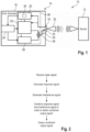
Figure 1 schematically shows an overview of a radar emulator according to an embodiment of the invention, and -
Figure 2 schematically shows an overview of a method of testing a radar sensor according to an embodiment of the invention. - The detailed description set forth below in connection with the appended drawings, where like numerals reference like elements, is intended as a description of various embodiments of the disclosed subject matter and is not intended to represent the only embodiments. Each embodiment described in this disclosure is provided merely as an example or illustration and should not be construed as preferred or advantageous over other embodiments. The illustrative examples provided herein are not intended to be exhaustive or to limit the claimed subject matter to the precise forms disclosed.
- For the purposes of the present disclosure, the phrase "at least one of A, B, and C", for example, means (A), (B), (C), (A and B), (A and C), (B and C), or (A, B, and C), including all further possible permutations when more than three elements are listed. In other words, the term "at least one of A and B" generally means "A and/or B", namely "A" alone, "B" alone or "A and B".
- In
Figure 1 , atest system 10 is shown that comprises aradar sensor 12 to be tested, namely a device under test (DUT), as well as aradar emulator 14 for testing theradar sensor 12. - The
radar sensor 12 may be a separately formed radar sensor or rather a radar sensor that is integrated within a device. - The
radar emulator 14 is a single device that has ahousing 16 that encompasses several components that are integrated within the single device, namely theradar emulator 14. - The
radar emulator 14 comprises aradar signal receiver 18 that is capable of receiving a radar signal with at least one characteristic, which has been transmitted by theradar sensor 12. The at least one characteristic may be a ramp of a frequency modulated continuous wave radar signal, a timing information of the radar signal and a frequency range of the radar signal. - The
radar signal receiver 18 is connected with aradar signal processor 20 that is capable of processing the radar signal received. - The
radar signal receiver 18 may be directly connected to aresponse signal generator 22 that is capable of generating a response signal. Alternatively or additionally, theresponse signal generator 22 is connected to theradar signal processor 20. - Actually, the respective connection(s) may depend on the computational power of the
response signal generator 22, namely whether theresponse signal generator 22 is capable of analyzing the radar signal received via theradar signal receiver 18 on its own or if the analysis of the radar signal received by theradar signal receiver 18 is done via theradar signal processor 20. - In any case, the
radar emulator 14 is used to generate the response signal that corresponds to a response to the radar signal received. Hence, the response signal may relate to an echo signal for theradar sensor 12. Consequently, theradar emulator 14 is also called echo generator. - In addition, the
radar emulator 14 comprises a user interface 24 that is connected to theradar signal processor 20, theresponse signal generator 22 as well as aninterference signal generator 26. A user of theradar emulator 14 may control theradar emulator 14 via the user interface 24, particularly components thereof. - The
interference signal generator 26 is capable of generating an interference signal, particularly based on settings done via the user interface 24. In other words, the interference signal may be generated based on a predefined waveform, wherein the user is enabled to set certain parameters of the interference signal via the user interface 24. - Since the
interference signal generator 26 is also connected (directly or indirectly via the user interface 24) with theradar signal processor 20, the interference signal may be generated (additionally or alternatively) based on at least one characteristic of the radar signal received that has been determined by theradar signal processor 20. In other words, the interference signal may be generated in an adaptive manner, namely depending on the radar signal received. - This is also shown in
Figure 1 by the respective arrows. In fact, the user interface 24 receives data from theradar signal processor 20 wherein the user interface 24 provides data to theresponse signal generator 22 and theinterference signal generator 26. The data provided to theresponse signal generator 22 and theinterference signal generator 26 may relate to settings done via the user interface 24 or rather the data obtained from theradar signal processor 20, particularly in case theradar signal processor 20 is not directly connected with theresponse signal generator 22 and theinterference signal generator 26. - In any case, information obtained from the
radar signal processor 20 may be forwarded to theresponse generator 22 and theinterference signal generator 26, either via the user interface 24 or directly. - Moreover, the
radar emulator 14 has an adder 28 that is connected to theresponse signal generator 22 and theinterference signal generator 26. - The adder 28 combines the interference signal generated by the
interference signal generator 26 as well as the response signal generated by theresponse signal generator 22. Hence, bothgenerators - The adder 28 is also connected with an
output interface 30 to which at least oneantenna 32 is connected. Thus, the combined output signal obtained by the adder 28 is output via theoutput interface 30 and the at least oneantenna 32, namely as a radio frequency (RF) signal. - In fact, the combined output signal is forwarded to the
radar sensor 12 over-the-air, wherein the combined output signal comprises the interference signal generated and the response signal generated. - The
radar sensor 12 receives the single output signal over-the-air, which comprises the response signal and the interference signal accordingly. - According to a certain embodiment, the adder 28 may relate to an analog adder that receives an analog interference signal as well as an analog response signal, wherein these analog signals are combined in an analog manner.
- According to an alternative embodiment, the adder 28 relates to a digital adder that receives a digital response signal and a digital interference signal, wherein these digital signals are processed/combined by the adder 28 in a digital manner. In this case, a digital to
analog converter 34 is provided between the adder 28 and theoutput interference 30 such that the digital combined output signal is converted into an analog signal by means of the digital toanalog converter 34, wherein the analog combined output signal obtained is forwarded to theoutput interface 30. - In the shown embodiment, the
radar emulator 14 comprises asingle hardware chip 36 on which theradar signal processor 20, theresponse signal generator 22, theinterference signal generator 26 as well as the adder 28 are implemented. - The
radar signal processor 20 may comprises anestimation circuit 38 that is used to estimate the at least one characteristic of the radar signal received when processing the radar signal received. Theestimation circuit 38 that estimates the at least one characteristic ensures fast processing. - Generally, the
radar signal processor 20 is a real-time processor (circuit) that determines the at least one characteristic of the radar signal received in real time. - Moreover, the entire
single hardware chip 26 may relate to a real-time processing hardware chip. - The
radar emulator 14 shown inFigure 1 is generally capable of performing a method of testing, a flow-chart of which is shown inFigure 2 . - In a first step, a radar signal from the
radar sensor 12 to be tested is received by theradar signal receiver 18, wherein the radar signal received comprises at least one characteristic. - In a second step, the response signal is generated by the
response signal generator 22. - In a third step, the interference signal is generated by the
interference signal generator 26. The interference signal is synchronized with the response signal in time. - The time synchronization can be ensured by means of the user interface 24, e.g. settings done via the user interface 24, and/or the
radar signal processor 20 that is connected with both theresponse signal generator 22 and theinterference signal generator 26. - In a fourth step, the interference signal and the response signal are combined by the adder 28 in order to obtain the combined output signal that comprises the response signal generated and the interference signal generated.
- In a fifth step, the combined output signal is output via the
output interface 30. - Specifically, the generation of the response signal and/or the interference signal may be based on the processing of the radar signal received by means of the
radar signal processor 20. Particularly, the response signal and/or the interference signal are generated based on the at least one characteristic of the radar signal received, which was determined/estimated by theradar signal processor 20, particularly theestimation circuit 38, when processing the radar signal received. - In general, the
response signal generator 22 generates the response signal based on the at least one characteristic of the radar signal that was determined or rather estimated. For instance, the at least one characteristic was determined/estimated by theresponse signal generator 22 itself or rather theradar signal processor 20. - Hence, the second step may relate to processing the radar signal received to generate the response signal, wherein the response signal is generated based on the at least one characteristic determined/estimated.
- Further, the
interference signal generator 26 generates the interference signal based on the at least one characteristic of the radar signal that was determined or rather estimated. - Hence, the third step may relate to processing the radar signal received to generate the interference signal, wherein the interference signal is based on the at least one characteristic determined/estimated and wherein the interference signal is synchronized to the response signal in time.
- Additionally or alternatively, the interference signal is generated based on a setting done by the user via the user interface 24. In fact, the user is enabled to set the
interference signal generator 26 via the user interface 24 in order to define a certain interference signal to be used in a testing scenario for testing theradar sensor 12. - The time synchronization of the interference signal and the response signal ensures that both signals occur simultaneously in a respective testing scenario.
- For instance, the
radar signal processor 20, when processing the radar signal received, generates a synchronization signal to be forwarded to theinterference signal generator 26 for synchronizing theinterference signal generator 26 with theresponse signal generator 22. - The respective synchronization signal may relate to a trigger signal, e.g. a trigger vector, that is derived from the radar signal received, wherein the trigger signal starts the
interference signal generator 26. In other words, the trigger signal triggers the starting of theinterference signal generator 26 such that theinterference signal generator 26 starts outputting the interference signal once the trigger signal is received. - Alternatively, the respective synchronization signal is based on detecting the radar signal received, wherein internal delays of the
radar emulator 14 are taken into account when controlling theinterference signal generator 26 and/or theresponse signal generator 22 such that both theinterference signal generator 26 and theresponse signal generator 22 output their respective generated signals. - The
interference signal generator 26 may be a numerically controlled oscillator, for instance with an increasing phase increment. - Certain embodiments disclosed herein, particularly the respective module(s) and/or unit(s), utilize circuitry (e.g., one or more circuits) in order to implement standards, protocols, methodologies or technologies disclosed herein, operably couple two or more components, generate information, process information, analyze information, generate signals, encode/decode signals, convert signals, transmit and/or receive signals, control other devices, etc. Circuitry of any type can be used.
- In an embodiment, circuitry includes, among other things, one or more computing devices such as a processor (e.g., a microprocessor), a central processing unit (CPU), a digital signal processor (DSP), an application-specific integrated circuit (ASIC), a field-programmable gate array (FPGA), a system on a chip (SoC), or the like, or any combinations thereof, and can include discrete digital or analog circuit elements or electronics, or combinations thereof. In an embodiment, circuitry includes hardware circuit implementations (e.g., implementations in analog circuitry, implementations in digital circuitry, and the like, and combinations thereof).
- In an embodiment, circuitry includes combinations of circuits and computer program products having software or firmware instructions stored on one or more computer readable memories that work together to cause a device to perform one or more protocols, methodologies or technologies described herein. In an embodiment, circuitry includes circuits, such as, for example, microprocessors or portions of microprocessor, that require software, firmware, and the like for operation. In an embodiment, circuitry includes one or more processors or portions thereof and accompanying software, firmware, hardware, and the like.
- The present application may reference quantities and numbers. Unless specifically stated, such quantities and numbers are not to be considered restrictive, but exemplary of the possible quantities or numbers associated with the present application. Also in this regard, the present application may use the term "plurality" to reference a quantity or number. In this regard, the term "plurality" is meant to be any number that is more than one, for example, two, three, four, five, etc. The terms "about", "approximately", "near" etc., mean plus or minus 5% of the stated value.
Claims (15)
- A radar emulator (14) for testing a radar sensor (12), the radar emulator (14) comprising- a radar signal receiver (18) configured to receive a radar signal having at least one characteristic,- a radar signal processor (20) configured to process the radar signal received,- a response signal generator (22) configured to generate a response signal to the radar signal received,- an interference signal generator (26) configured to generate an interference signal that is synchronized with the response signal in time, and- an adder (28) configured to combine the interference signal and the response signal in order to obtain a combined output signal that comprises the response signal generated and the interference signal generated.
- The radar emulator (14) according to claim 1, wherein the response signal generator (22) is configured to generate the response signal based on the at least one characteristic of the radar signal.
- The radar emulator (14) according to claim 1 or 2, wherein the interference signal generator (26) is configured to generate the interference signal based on the at least one characteristic of the radar signal.
- The radar emulator (14) according to any one of the preceding claims, wherein the at least one characteristic is at least one of a ramp of a frequency modulated continuous wave radar signal, a timing information of the radar signal and a frequency range of the radar signal.
- The radar emulator (14) according to any one of the preceding claims, wherein the radar signal processor (20) comprises an estimation circuit (38) that is configured to estimate the at least one characteristic when processing the radar signal received.
- The radar emulator (14) according to any one of the preceding claims, wherein the radar signal processor (20) is a real-time processor that is configured to determine the at least one characteristic in real time, in particular wherein the real-time processor is configured to adapt a setting of the response signal generator (22) and/or a setting of the interference signal generator (26) in real time.
- The radar emulator (14) according to any one of the preceding claims, wherein the adder (28) is a digital adder that is configured to process the interference signal and the response signal in a digital manner in order to obtain a digital combined output signal or wherein the adder (28) is an analog adder that is configured to process the interference signal and the response signal in an analog manner in order to obtain an analog combined output signal.
- The radar emulator (14) according to any one of the preceding claims, wherein the radar emulator (14) comprises a user interface (24) that is connected with the interference signal generator (26) such that the user is enabled to set the interference signal generator (26) via the user interface (24).
- The radar emulator (14) according to any one of the preceding claims, wherein the radar signal processor (20) is configured to generate a synchronization signal to be forwarded to the interference signal generator (26) for synchronizing the interference signal generator (26) and the response signal generator (22).
- The radar emulator (14) according to any one of the preceding claims, wherein the radar signal receiver (18), the radar signal processor (20), the response signal generator (22) and/or the interference signal generator (26) are established on a single hardware chip (36).
- A method of testing a radar sensor (12), with the following steps:- Receiving a radar signal from the radar sensor (12) to be tested, which comprises at least one characteristic,- Generating a response signal,- Generating an interference signal, wherein the interference signal is synchronized to the response signal in time, and- Combining the interference signal and the response signal in order to obtain a combined output signal that comprises the response signal generated and the interference signal generated.
- The method according to claim 11, wherein the interference signal and the response signal are digital signals that are combined such that a digital combined output signal is obtained.
- The method according to claim 11 or 12, wherein at least one of the response signal and the interference signal is generated based on the at least one characteristic of the radar signal.
- The method according to any one of claims 11 to 13, wherein at least one of a setting of a response signal generator (22) and a setting of an interference signal generator (26) is set in real time and/or wherein the at least one characteristic of the radar signal received is determined in real time.
- The method according to any one of claims 11 to 14, wherein a synchronization signal is generated and forwarded to an interference signal generator (26) for synchronizing the interference signal generator and a response signal generator (22) and/or wherein a trigger signal is derived from the radar signal received that starts outputting the interference signal.
Applications Claiming Priority (1)
| Application Number | Priority Date | Filing Date | Title |
|---|---|---|---|
| US18/317,727 US12560683B2 (en) | 2023-05-15 | 2023-05-15 | Radar emulator and method of testing a radar sensor |
Publications (1)
| Publication Number | Publication Date |
|---|---|
| EP4465075A1 true EP4465075A1 (en) | 2024-11-20 |
Family
ID=90368501
Family Applications (1)
| Application Number | Title | Priority Date | Filing Date |
|---|---|---|---|
| EP24164943.3A Pending EP4465075A1 (en) | 2023-05-15 | 2024-03-20 | Radar emulator and method of testing a radar sensor |
Country Status (3)
| Country | Link |
|---|---|
| US (1) | US12560683B2 (en) |
| EP (1) | EP4465075A1 (en) |
| CN (1) | CN118962604A (en) |
Cited By (2)
| Publication number | Priority date | Publication date | Assignee | Title |
|---|---|---|---|---|
| DE102024104982A1 (en) * | 2024-02-22 | 2025-08-28 | Dspace Gmbh | Environmental sensor test device, test arrangement for an environmental sensor and method for operating the environmental sensor test device |
| DE102024118902A1 (en) * | 2024-07-03 | 2026-01-08 | Dspace Gmbh | Object simulator for a sensor for object detection and method for simulating an object |
Citations (6)
| Publication number | Priority date | Publication date | Assignee | Title |
|---|---|---|---|---|
| US20060267832A1 (en) * | 2004-03-11 | 2006-11-30 | Newberg Irwin L | Arbitrary radar target synthesizer (arts) |
| US20160245900A1 (en) * | 2015-02-19 | 2016-08-25 | Teradyne, Inc. | Virtual distance test techniques for radar applications |
| US10613198B2 (en) * | 2017-04-24 | 2020-04-07 | Honeywell International Inc. | System and method for testing integrated radar systems |
| US20200300968A1 (en) * | 2016-12-29 | 2020-09-24 | Avl List Gmbh | Switching device for a radar target emulator and radar target emulator having said type of switching device |
| US20210341572A1 (en) * | 2020-04-29 | 2021-11-04 | Rohde & Schwarz Gmbh & Co. Kg | Test system for testing a radar sensor |
| US20220099824A1 (en) * | 2020-09-25 | 2022-03-31 | Rohde & Schwarz Gmbh & Co. Kg | Radar target simulation system and radar target simulation method |
Family Cites Families (7)
| Publication number | Priority date | Publication date | Assignee | Title |
|---|---|---|---|---|
| US5047782A (en) * | 1990-06-04 | 1991-09-10 | Westinghouse Electric Corp. | System and method for simulating targets for a radar receiver utilizing an optical link |
| IL102119A (en) * | 1991-06-05 | 1995-11-27 | Commw Of Australia | Radar environment generator |
| US5223840A (en) * | 1992-03-13 | 1993-06-29 | The United States Of America As Represented By The Secretary Of The Navy | Low cost radar target simulator for remote radar testing |
| US7327308B2 (en) * | 2005-04-28 | 2008-02-05 | Chung Shan Institute Of Science And Technology, Armaments Bureau, M.N.D. | Programmable method and test device for generating target for FMCW radar |
| US10527715B2 (en) * | 2016-06-20 | 2020-01-07 | Rohde & Schwarz Gmbh & Co. Kg | Radar target stimulation device and method |
| US10509107B2 (en) * | 2017-01-13 | 2019-12-17 | Rohde & Schwarz Gmbh & Co. Kg | Device, system and method for simulating at least one echo signal of an electromagnetic signal |
| WO2019060901A1 (en) | 2017-09-25 | 2019-03-28 | Bridger Photonics, Inc. | Digitization systems and techniques and examples of use in fmcw lidar methods and apparatuses |
-
2023
- 2023-05-15 US US18/317,727 patent/US12560683B2/en active Active
-
2024
- 2024-03-20 EP EP24164943.3A patent/EP4465075A1/en active Pending
- 2024-03-22 CN CN202410336892.6A patent/CN118962604A/en active Pending
Patent Citations (6)
| Publication number | Priority date | Publication date | Assignee | Title |
|---|---|---|---|---|
| US20060267832A1 (en) * | 2004-03-11 | 2006-11-30 | Newberg Irwin L | Arbitrary radar target synthesizer (arts) |
| US20160245900A1 (en) * | 2015-02-19 | 2016-08-25 | Teradyne, Inc. | Virtual distance test techniques for radar applications |
| US20200300968A1 (en) * | 2016-12-29 | 2020-09-24 | Avl List Gmbh | Switching device for a radar target emulator and radar target emulator having said type of switching device |
| US10613198B2 (en) * | 2017-04-24 | 2020-04-07 | Honeywell International Inc. | System and method for testing integrated radar systems |
| US20210341572A1 (en) * | 2020-04-29 | 2021-11-04 | Rohde & Schwarz Gmbh & Co. Kg | Test system for testing a radar sensor |
| US20220099824A1 (en) * | 2020-09-25 | 2022-03-31 | Rohde & Schwarz Gmbh & Co. Kg | Radar target simulation system and radar target simulation method |
Cited By (2)
| Publication number | Priority date | Publication date | Assignee | Title |
|---|---|---|---|---|
| DE102024104982A1 (en) * | 2024-02-22 | 2025-08-28 | Dspace Gmbh | Environmental sensor test device, test arrangement for an environmental sensor and method for operating the environmental sensor test device |
| DE102024118902A1 (en) * | 2024-07-03 | 2026-01-08 | Dspace Gmbh | Object simulator for a sensor for object detection and method for simulating an object |
Also Published As
| Publication number | Publication date |
|---|---|
| US20240385288A1 (en) | 2024-11-21 |
| CN118962604A (en) | 2024-11-15 |
| US12560683B2 (en) | 2026-02-24 |
Similar Documents
| Publication | Publication Date | Title |
|---|---|---|
| US10386470B2 (en) | Radar system | |
| US12560683B2 (en) | Radar emulator and method of testing a radar sensor | |
| US10473773B2 (en) | Time synchronization of spatially separated radars | |
| CN102770781B (en) | Pulse radar device and method for controlling the same | |
| US8816900B2 (en) | Radar device, calibration system and calibration method | |
| US9170323B2 (en) | Pulse radar range profile motion compensation | |
| CN103430041B (en) | Pulse radar device and control method thereof | |
| JP2012103203A (en) | Fmcw radar device | |
| JP2007232383A (en) | Electronic scanning radar equipment | |
| US7688239B2 (en) | Fault detection apparatus for detecting failure of A/D converter due to loss of externally supplied clock signal | |
| JP6324327B2 (en) | Passive radar equipment | |
| JP2008275382A (en) | FM-CW polarization radar equipment | |
| JP2007232385A (en) | Electronic scanning radar equipment | |
| CN105388463A (en) | Reception signal processing device, radar, and object detection method | |
| US7755538B2 (en) | Radar apparatus | |
| JP2013137268A (en) | Fmcw radar system | |
| JP4249057B2 (en) | FM-CW radar | |
| JP2007500857A (en) | Method and apparatus for simulating a Doppler signal for self-testing an altimeter in a stationary state | |
| JP2001272464A (en) | Radar equipment | |
| JP2010281596A (en) | Temperature compensated distance detector | |
| US8188909B2 (en) | Observation signal processing apparatus | |
| JP2005241602A (en) | Radar test method and apparatus | |
| JP6976189B2 (en) | Object detector | |
| RU2293997C1 (en) | Method for correlation processing of signals, reflected from fast-moving targets | |
| US11422159B2 (en) | Measurement device with arbitrary waveform generator and trigger unit |
Legal Events
| Date | Code | Title | Description |
|---|---|---|---|
| PUAI | Public reference made under article 153(3) epc to a published international application that has entered the european phase |
Free format text: ORIGINAL CODE: 0009012 |
|
| STAA | Information on the status of an ep patent application or granted ep patent |
Free format text: STATUS: THE APPLICATION HAS BEEN PUBLISHED |
|
| AK | Designated contracting states |
Kind code of ref document: A1 Designated state(s): AL AT BE BG CH CY CZ DE DK EE ES FI FR GB GR HR HU IE IS IT LI LT LU LV MC ME MK MT NL NO PL PT RO RS SE SI SK SM TR |
|
| STAA | Information on the status of an ep patent application or granted ep patent |
Free format text: STATUS: REQUEST FOR EXAMINATION WAS MADE |
|
| 17P | Request for examination filed |
Effective date: 20250515 |