EP4465065A2 - Method to determine quality of termination of wire using thermal characteristics - Google Patents
Method to determine quality of termination of wire using thermal characteristics Download PDFInfo
- Publication number
- EP4465065A2 EP4465065A2 EP24195950.1A EP24195950A EP4465065A2 EP 4465065 A2 EP4465065 A2 EP 4465065A2 EP 24195950 A EP24195950 A EP 24195950A EP 4465065 A2 EP4465065 A2 EP 4465065A2
- Authority
- EP
- European Patent Office
- Prior art keywords
- termination
- thermal
- wire
- crimp
- crimping
- Prior art date
- Legal status (The legal status is an assumption and is not a legal conclusion. Google has not performed a legal analysis and makes no representation as to the accuracy of the status listed.)
- Pending
Links
Images
Classifications
-
- G—PHYSICS
- G01—MEASURING; TESTING
- G01R—MEASURING ELECTRIC VARIABLES; MEASURING MAGNETIC VARIABLES
- G01R31/00—Arrangements for testing electric properties; Arrangements for locating electric faults; Arrangements for electrical testing characterised by what is being tested not provided for elsewhere
- G01R31/50—Testing of electric apparatus, lines, cables or components for short-circuits, continuity, leakage current or incorrect line connections
- G01R31/66—Testing of connections, e.g. of plugs or non-disconnectable joints
-
- H—ELECTRICITY
- H01—ELECTRIC ELEMENTS
- H01R—ELECTRICALLY-CONDUCTIVE CONNECTIONS; STRUCTURAL ASSOCIATIONS OF A PLURALITY OF MUTUALLY-INSULATED ELECTRICAL CONNECTING ELEMENTS; COUPLING DEVICES; CURRENT COLLECTORS
- H01R43/00—Apparatus or processes specially adapted for manufacturing, assembling, maintaining, or repairing of line connectors or current collectors or for joining electric conductors
- H01R43/04—Apparatus or processes specially adapted for manufacturing, assembling, maintaining, or repairing of line connectors or current collectors or for joining electric conductors for forming connections by deformation, e.g. crimping tool
- H01R43/048—Crimping apparatus or processes
-
- G—PHYSICS
- G01—MEASURING; TESTING
- G01N—INVESTIGATING OR ANALYSING MATERIALS BY DETERMINING THEIR CHEMICAL OR PHYSICAL PROPERTIES
- G01N25/00—Investigating or analyzing materials by the use of thermal means
- G01N25/18—Investigating or analyzing materials by the use of thermal means by investigating thermal conductivity
-
- G—PHYSICS
- G01—MEASURING; TESTING
- G01R—MEASURING ELECTRIC VARIABLES; MEASURING MAGNETIC VARIABLES
- G01R31/00—Arrangements for testing electric properties; Arrangements for locating electric faults; Arrangements for electrical testing characterised by what is being tested not provided for elsewhere
- G01R31/50—Testing of electric apparatus, lines, cables or components for short-circuits, continuity, leakage current or incorrect line connections
- G01R31/66—Testing of connections, e.g. of plugs or non-disconnectable joints
- G01R31/68—Testing of releasable connections, e.g. of terminals mounted on a printed circuit board
- G01R31/69—Testing of releasable connections, e.g. of terminals mounted on a printed circuit board of terminals at the end of a cable or a wire harness; of plugs; of sockets, e.g. wall sockets or power sockets in appliances
-
- H—ELECTRICITY
- H01—ELECTRIC ELEMENTS
- H01R—ELECTRICALLY-CONDUCTIVE CONNECTIONS; STRUCTURAL ASSOCIATIONS OF A PLURALITY OF MUTUALLY-INSULATED ELECTRICAL CONNECTING ELEMENTS; COUPLING DEVICES; CURRENT COLLECTORS
- H01R43/00—Apparatus or processes specially adapted for manufacturing, assembling, maintaining, or repairing of line connectors or current collectors or for joining electric conductors
- H01R43/02—Apparatus or processes specially adapted for manufacturing, assembling, maintaining, or repairing of line connectors or current collectors or for joining electric conductors for soldered or welded connections
- H01R43/0207—Ultrasonic-, H.F.-, cold- or impact welding
-
- H—ELECTRICITY
- H01—ELECTRIC ELEMENTS
- H01R—ELECTRICALLY-CONDUCTIVE CONNECTIONS; STRUCTURAL ASSOCIATIONS OF A PLURALITY OF MUTUALLY-INSULATED ELECTRICAL CONNECTING ELEMENTS; COUPLING DEVICES; CURRENT COLLECTORS
- H01R43/00—Apparatus or processes specially adapted for manufacturing, assembling, maintaining, or repairing of line connectors or current collectors or for joining electric conductors
- H01R43/02—Apparatus or processes specially adapted for manufacturing, assembling, maintaining, or repairing of line connectors or current collectors or for joining electric conductors for soldered or welded connections
- H01R43/0214—Resistance welding
-
- H—ELECTRICITY
- H01—ELECTRIC ELEMENTS
- H01R—ELECTRICALLY-CONDUCTIVE CONNECTIONS; STRUCTURAL ASSOCIATIONS OF A PLURALITY OF MUTUALLY-INSULATED ELECTRICAL CONNECTING ELEMENTS; COUPLING DEVICES; CURRENT COLLECTORS
- H01R43/00—Apparatus or processes specially adapted for manufacturing, assembling, maintaining, or repairing of line connectors or current collectors or for joining electric conductors
- H01R43/04—Apparatus or processes specially adapted for manufacturing, assembling, maintaining, or repairing of line connectors or current collectors or for joining electric conductors for forming connections by deformation, e.g. crimping tool
- H01R43/048—Crimping apparatus or processes
- H01R43/0486—Crimping apparatus or processes with force measuring means
-
- Y—GENERAL TAGGING OF NEW TECHNOLOGICAL DEVELOPMENTS; GENERAL TAGGING OF CROSS-SECTIONAL TECHNOLOGIES SPANNING OVER SEVERAL SECTIONS OF THE IPC; TECHNICAL SUBJECTS COVERED BY FORMER USPC CROSS-REFERENCE ART COLLECTIONS [XRACs] AND DIGESTS
- Y10—TECHNICAL SUBJECTS COVERED BY FORMER USPC
- Y10T—TECHNICAL SUBJECTS COVERED BY FORMER US CLASSIFICATION
- Y10T29/00—Metal working
- Y10T29/49—Method of mechanical manufacture
- Y10T29/49002—Electrical device making
- Y10T29/49004—Electrical device making including measuring or testing of device or component part
-
- Y—GENERAL TAGGING OF NEW TECHNOLOGICAL DEVELOPMENTS; GENERAL TAGGING OF CROSS-SECTIONAL TECHNOLOGIES SPANNING OVER SEVERAL SECTIONS OF THE IPC; TECHNICAL SUBJECTS COVERED BY FORMER USPC CROSS-REFERENCE ART COLLECTIONS [XRACs] AND DIGESTS
- Y10—TECHNICAL SUBJECTS COVERED BY FORMER USPC
- Y10T—TECHNICAL SUBJECTS COVERED BY FORMER US CLASSIFICATION
- Y10T29/00—Metal working
- Y10T29/53—Means to assemble or disassemble
- Y10T29/5313—Means to assemble electrical device
- Y10T29/532—Conductor
- Y10T29/53209—Terminal or connector
Definitions
- the invention relates to a method and system for monitoring the quality of a termination of a wire using thermal characteristics of the termination.
- Wires are terminated using a variety of methods, such as, crimping, soldering or welding.
- electrical terminals are typically crimped onto wires by a crimping apparatus to form a lead.
- the crimping apparatus has crimp tooling made up of a first part mounted to a base for supporting the electrical terminal and a second part mounted to a ram that is movable toward and away from the base for effecting the crimp.
- the terminal is placed on the first part of the crimp tooling and an end of a wire is inserted into the ferrule or barrel of the terminal.
- the ram is caused to move toward the base through a crimp stroke, thereby crimping the terminal onto the wire.
- wire termination monitoring system and method which can be used to monitor different terminations of wires.
- wire termination monitoring system and method which does not solely measure force or dimensions, but monitors the thermal characteristics of the termination.
- An embodiment is directed to a crimping apparatus which allows for determining the quality of a crimp.
- the apparatus includes an applicator which has an anvil and a crimp tool which is movable relative to the anvil, The anvil and a crimp tool define a crimping zone of the apparatus.
- a thermal sensor is mounted on the crimping apparatus proximate the applicator. The thermal sensor monitors the thermal properties of the crimp made by the applicator to determine if the crimp is defective.
- An embodiment is directed to a method of determining the quality of a termination of a wire or terminal.
- the method includes: terminating the wire; monitoring the thermal properties of the termination with one or more thermal sensors; and comparing the monitored thermal properties to stored thermal properties to determine if the termination is defective. If the termination is defective, the termination is discarded.
- FIG. 1 A device ( FIG. 1 ) and method of monitoring the crimping processes ( FIGS. 2 and 3) for the purpose of determining crimp quality by using thermal characteristics and signatures is shown.
- the use of the crimping machine is meant to be illustrative and not limiting.
- the use of thermal data and analysis, as described below, to monitor the termination of wires, conductors or terminals has other uses beyond just crimp related applications.
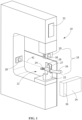
- FIG. 1 is a perspective view of a crimping machine 10 having an applicator 12.
- the crimping machine 10 is illustrated as a terminal crimping machine used for crimping terminals to wires, however, other types of machines may be used, such as an insulation displacement connector (IDC) machine, a welding machine, and the like, that attach connectors to wires using processes other than crimping.
- the crimping machine 10 may be another type of crimping machine such as a lead frame machine.
- the applicator 12 is coupled to the crimping machine 10.
- the applicator 12 may be removed and replaced with a different applicator, such as when the applicator 12 is worn or damaged or when an applicator having a different configuration is desired.
- the applicator 12 has a terminating zone or crimping zone 18 and includes a crimper or crimp tooling 20 and an anvil 22 as the mechanical tooling for crimping electrical connectors or terminals 24 to an end of a wire 26 in the crimping zone 18.
- the anvil 22 is a stationary component of the applicator 12, and the crimp tooling 20 represents a movable component.
- One or more thermal sensors 28 are mounted to the crimping machine 10.
- the thermal sensors 28 may be mounted at various locations in or proximate to the crimping zone 18.
- the thermal sensors 28 may be removably mounted by a removable device, such as, but not limited to, a magnet (not shown).
- the thermal sensors 28 may be held in place by using mechanical fasteners, latches, adhesives, and the like. While the thermal sensors 28 are shown circular members, the thermal sensors 28 may have other shapes.
- each of the thermal sensors 28 are positioned to have a field of view that includes the crimping zone 18.
- the thermal sensors 28 are positioned to acquire the thermal characteristics, in the form of discrete thermal data, of the terminal 24 and/or the wire 26 in the crimping zone 18.
- at least one of the thermal sensor 28 is positioned in-line with a longitudinal axis 42 of the anvil 22 and a barrel 27 of the terminal 24. This allows the thermal sensor 28 to directly sense and collect the thermal data from the thermal energy that is emitted directly from the terminal 24 and/or the wire 26.
- one or more of the thermal sensors 28 may be positioned out-of-line or off-center from the axis 42.
- those thermal sensors 28 may collect thermal energy that is transferred through the terminal 24 to the wire 26 or to another object and/or those thermal sensors 28 may collect thermal energy which is reflected off the terminal 24 and/or the wire 26.
- thermo sensor 28 positioning bodies or objects around the terminal 24 and/or wire 26 which are configured to intentionally reflect or direct thermal energy from the terminal 24 and/or the wire 26 being sensed would allow a thermal sensor 28 to be out-of-line or off-center from the terminal 24 and read thermal data that is reflected from the surrounding bodies or objects. Construction of these surrounding bodies could be done with materials of known emissivity to enhance the reflected imaging of the thermal characteristics of the terminal 24 and/or the wire 26 being terminated. This would allow the ability to thermally "sense" areas that would not be easy viewed or to view more surface area of the terminal 24 and/or the wire 26 with fewer sensors.
- the thermal data collected by the one or more thermal sensors 28 may be one or a combination of three distinct components of energy.
- the first is thermal energy emitted directly from the terminal 24 and/or the wire 26.
- the second is thermal energy that is transferred through the object (heat from somewhere else that passes through) such as from the terminal 24 to the wire 26.
- the third is thermal energy reflected off the terminal 24 and/or the wire 26.
- the thermal data is captured by a plurality of sensors 28 arranged in a matrix (such as a charge coupled device network) which allows the thermal data to be captured and arranged in rows and columns - similar to how pixels of data describe a visual image collected with a conventional visual energy camera.
- a matrix such as a charge coupled device network
- one thermal sensor may be positioned in-line with the longitudinal axis of the of the terminal, while other thermal sensors of the matrix may be positioned out-of-line or off-center from the axis.
- techniques such as but not limited to, an adapted convolution neural network, are used to extract features from these matrices of data to analyze the process of a crimp before, during and after the crimp has been formed.
- the characteristics and signatures of the thermal data collect may include, but are not limited to: i) area heating; ii) heat transfer times; iii) heat transfer patterns; iv) temperature delta v) physical characteristics and variations identified through thermal properties.
- the thermal data can be collected at various rates, which results in a time series of images.
- analysis techniques such as, but not limited to artificial intelligence, the time varying data can be analyzed.
- the thermal sensors 28 have the ability to collect absolute temperatures. Absolute temperatures provide the potential for not just analyzing "relative" regions of interest but potentially distinct mechanical characteristics of the termination.
- a display device 32 may be communicatively coupled to the thermal sensor 28 and configured to display the thermal characteristics acquired by the thermal sensor 28.
- the display device 32 may be integrated into a host controller or processor of the crimping machine 10 itself or may be a separate controller or processor 34, such as a desktop computer, a laptop computer, a tablet computer, a monitor, a projector, and the like.
- the display device 32 may be a crimp quality monitor (CQM) device.
- the controller 34 and/or display device 32 may be coupled to the thermal sensor 28 through a cable or the like.
- the controller 34 and/or display device 32 may communicate wirelessly through induction, radio frequency waves, Wi-Fi, and the like to transmit data between the thermal sensor 28 and the controller 34 and/or display device 32.
- the controller 34 and/or display device may include a storage or memory device 36 such as, but not limited to, a hard disk drive, RAM, ROM, and/or another internal data storage device.
- the memory device 36 may be configured to store data acquired by the thermal sensor 28. Such data may be used for subsequent quality reporting purposes.
- the crimping machine 10 may include additional sensors 38, such as, but not limited to, a force sensor or a linear sensor to provide additional data with respect to the quality of the crimp.
- additional sensors 38 such as, but not limited to, a force sensor or a linear sensor to provide additional data with respect to the quality of the crimp.
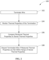
- FIG. 2 illustrates the method of determining the quality of a termination 100.
- the crimp stroke has both a downward component and an upward component.
- the crimping of the terminal 24 to the wire 26 occurs during the downward component of the crimp stroke.
- the crimp tooling 20 engages the terminal 24 and crimps the terminal 24 onto the wire 26 by compressing the terminal 24 between the crimp tooling 20 and the anvil 22. As this occurs, thermal energy or heat is produced in the terminals and the wires within and proximate to the crimp.
- the collected temperature measurements/data is transmitted to the display device 32, the controller 34 or the memory device 36, either on the crimping machine 10 or at an external location from the crimping machine 10.
- the temperature measurements/data transmitted by the thermal sensor 28 is used by an operator of the crimping machine 10 to be able to determine if the termination of the wire meets appropriate standards to provide the desired electrical and mechanical connection.
- the terms "operator” is used herein to identify the machine or person operating or controlling the crimping machine 10.
- the quality of the crimp may be monitored 18.
- other characteristics of the crimp may be analyzed. For example, the temperature may be used to calculate the forces imported onto the terminal 24, as the amount of force is related to the temperature of the terminal 24 after crimping has occurred.
- the sensors 28 are activated and send data to the controller 34.
- the thermal characteristics of the crimp are measured, either directly or indirectly, during the crimp stroke by the one or more thermal sensors 28.
- the thermal characteristics are measured at predetermined intervals based on either time or crimp tooling position. For example, a predetermined sample time may be selected, and the thermal characteristics may be measured at each of the discrete sample times. Alternatively, or additionally, the thermal characteristics may be measured when the crimp tooling is at a predetermined crimp height position. The position of the crimp tooling may be detected by a distance sensor (not shown) or the like.
- the controller 32 may create a measured temperature profile of the crimp based on the measured thermal characteristics.
- the measured thermal profile is then compared to an acceptable temperature profile or an acceptable temperature profile range of known successful crimps, as represented by 106 in FIG. 2 .
- the measured thermal characteristics may be compared to known acceptable temperature characteristics or profiles of the particular materials being used.
- the acceptable temperature profile or an acceptable temperature profile range may be preinstalled in the controller 32 or may be developed by the user on-site and stored in the controller 32. If the measured temperature profile is within the acceptable temperature profile range, the controller 32 will indicate that the crimp is proper. If the measured temperature profile is not within the acceptable temperature profile range, the controller 32 will indicate that the crimp is not acceptable and reject the crimp, as represented by 108 in FIG. 2 .
- Data relating to the thermal characteristics, the peak temperature, the amount of area below the temperature curve, the shape of the temperature curve, or any combination may be analyzed to determine if the crimp is defective.
- thermal analysis of welds (ultrasonic, resistive, etc.), molding, stamping, thermoplastic welding and heat staking (plastic riveting) is beneficial to determine if a proper electrical connection has been secured.
- the thermal sensors may be used to collect thermal data during the termination process, allowing the controller to continue the terminal process until such time that a good termination/connection is achieved.
- thermal data By collecting thermal data during the crimping process, either by non-contact methods such as thermal sensors or by direct contact thermal sensors or both the data can be used to provide a quality assessment without the need for destructive testing.
- the thermal data can be used to create nondestructive 3D thermal cross sectioning. The use of the thermal data is beneficial in many applications, particularly in applications in which there is very little force variation between crimping a terminal with a wire or crimping one without a wire, for example, when crimping aluminum wire.
- a wire terminating apparatus which allows for determining the quality of a termination of a wire, the apparatus comprising: a wire termination zone; a thermal sensor mounted on the wire terminating apparatus proximate the wire termination zone; wherein the thermal sensor monitors the thermal properties of the termination to determine if the termination is defective.
- thermal sensors are mounted on the wire terminating apparatus proximate the wire termination zone.
- the thermal sensor is removably mounted to the wire terminating apparatus.
- the thermal sensor is positioned to have a field of view of the wire termination zone.
- the thermal sensor is positioned in line with a longitudinal axis of the wire positioned in the wire termination zone.
- the thermal sensor is positioned off centered from a longitudinal axis of a wire positioned in the wire termination zone, wherein the thermal sensor monitors the thermal properties of the termination which are reflected.
- the wire termination zone has an anvil and a crimp tool which is movable relative to the anvil, the anvil and a crimp tool defining a crimping zone of the wire terminating apparatus.
- the wire termination zone is a heating zone.
Landscapes
- Manufacturing & Machinery (AREA)
- Engineering & Computer Science (AREA)
- General Physics & Mathematics (AREA)
- Physics & Mathematics (AREA)
- Health & Medical Sciences (AREA)
- Chemical & Material Sciences (AREA)
- Analytical Chemistry (AREA)
- Biochemistry (AREA)
- General Health & Medical Sciences (AREA)
- Life Sciences & Earth Sciences (AREA)
- Immunology (AREA)
- Pathology (AREA)
- Manufacturing Of Electrical Connectors (AREA)
- Investigating Or Analyzing Materials Using Thermal Means (AREA)
Abstract
Description
- The invention relates to a method and system for monitoring the quality of a termination of a wire using thermal characteristics of the termination.
- Wires are terminated using a variety of methods, such as, crimping, soldering or welding. For example, electrical terminals are typically crimped onto wires by a crimping apparatus to form a lead. The crimping apparatus has crimp tooling made up of a first part mounted to a base for supporting the electrical terminal and a second part mounted to a ram that is movable toward and away from the base for effecting the crimp. In operation, the terminal is placed on the first part of the crimp tooling and an end of a wire is inserted into the ferrule or barrel of the terminal. The ram is caused to move toward the base through a crimp stroke, thereby crimping the terminal onto the wire.
- It would, therefore, be beneficial to provide a wire termination monitoring system and method which can be used to monitor different terminations of wires. In particular, it would be beneficial to provide a wire termination monitoring system and method which does not solely measure force or dimensions, but monitors the thermal characteristics of the termination.
- An embodiment is directed to a crimping apparatus which allows for determining the quality of a crimp. The apparatus includes an applicator which has an anvil and a crimp tool which is movable relative to the anvil, The anvil and a crimp tool define a crimping zone of the apparatus. A thermal sensor is mounted on the crimping apparatus proximate the applicator. The thermal sensor monitors the thermal properties of the crimp made by the applicator to determine if the crimp is defective.
- An embodiment is directed to a method of determining the quality of a termination of a wire or terminal. The method includes: terminating the wire; monitoring the thermal properties of the termination with one or more thermal sensors; and comparing the monitored thermal properties to stored thermal properties to determine if the termination is defective. If the termination is defective, the termination is discarded.
- The invention will now be described by way of example with reference to the accompanying drawings in which:
-
FIG. 1 is a perspective view of an illustrative crimping apparatus using thermal sensors to monitor the quality of crimp. -
FIG. 2 is a flowchart illustrating an illustrative method of monitoring the quality of a wire termination using thermal properties. - A device (
FIG. 1 ) and method of monitoring the crimping processes (FIGS. 2 and 3) for the purpose of determining crimp quality by using thermal characteristics and signatures is shown. However, the use of the crimping machine is meant to be illustrative and not limiting. The use of thermal data and analysis, as described below, to monitor the termination of wires, conductors or terminals has other uses beyond just crimp related applications. -
FIG. 1 is a perspective view of acrimping machine 10 having anapplicator 12. Thecrimping machine 10 is illustrated as a terminal crimping machine used for crimping terminals to wires, however, other types of machines may be used, such as an insulation displacement connector (IDC) machine, a welding machine, and the like, that attach connectors to wires using processes other than crimping. Alternatively, thecrimping machine 10 may be another type of crimping machine such as a lead frame machine. - The
applicator 12 is coupled to thecrimping machine 10. Theapplicator 12 may be removed and replaced with a different applicator, such as when theapplicator 12 is worn or damaged or when an applicator having a different configuration is desired. Theapplicator 12 has a terminating zone orcrimping zone 18 and includes a crimper orcrimp tooling 20 and ananvil 22 as the mechanical tooling for crimping electrical connectors orterminals 24 to an end of awire 26 in thecrimping zone 18. Theanvil 22 is a stationary component of theapplicator 12, and thecrimp tooling 20 represents a movable component. - One or more
thermal sensors 28 are mounted to thecrimping machine 10. Thethermal sensors 28 may be mounted at various locations in or proximate to thecrimping zone 18. Thethermal sensors 28 may be removably mounted by a removable device, such as, but not limited to, a magnet (not shown). Alternatively, thethermal sensors 28 may be held in place by using mechanical fasteners, latches, adhesives, and the like. While thethermal sensors 28 are shown circular members, thethermal sensors 28 may have other shapes. - In an exemplary embodiment, each of the
thermal sensors 28 are positioned to have a field of view that includes thecrimping zone 18. Thethermal sensors 28 are positioned to acquire the thermal characteristics, in the form of discrete thermal data, of theterminal 24 and/or thewire 26 in thecrimping zone 18. In an exemplary embodiment, at least one of thethermal sensor 28 is positioned in-line with alongitudinal axis 42 of theanvil 22 and abarrel 27 of theterminal 24. This allows thethermal sensor 28 to directly sense and collect the thermal data from the thermal energy that is emitted directly from theterminal 24 and/or thewire 26. In an alternate embodiment, one or more of thethermal sensors 28 may be positioned out-of-line or off-center from theaxis 42. If one or more of thesensors 28 are positioned out-of-line or off-center from theaxis 42, thosethermal sensors 28 may collect thermal energy that is transferred through theterminal 24 to thewire 26 or to another object and/or thosethermal sensors 28 may collect thermal energy which is reflected off theterminal 24 and/or thewire 26. - For example, positioning bodies or objects around the
terminal 24 and/orwire 26 which are configured to intentionally reflect or direct thermal energy from theterminal 24 and/or thewire 26 being sensed would allow athermal sensor 28 to be out-of-line or off-center from theterminal 24 and read thermal data that is reflected from the surrounding bodies or objects. Construction of these surrounding bodies could be done with materials of known emissivity to enhance the reflected imaging of the thermal characteristics of theterminal 24 and/or thewire 26 being terminated. This would allow the ability to thermally "sense" areas that would not be easy viewed or to view more surface area of theterminal 24 and/or thewire 26 with fewer sensors. - As previously stated, the thermal data collected by the one or more
thermal sensors 28 may be one or a combination of three distinct components of energy. The first is thermal energy emitted directly from theterminal 24 and/or thewire 26. The second is thermal energy that is transferred through the object (heat from somewhere else that passes through) such as from theterminal 24 to thewire 26. The third is thermal energy reflected off theterminal 24 and/or thewire 26. - In one exemplary embodiment, the thermal data is captured by a plurality of
sensors 28 arranged in a matrix (such as a charge coupled device network) which allows the thermal data to be captured and arranged in rows and columns - similar to how pixels of data describe a visual image collected with a conventional visual energy camera. For example, one thermal sensor may be positioned in-line with the longitudinal axis of the of the terminal, while other thermal sensors of the matrix may be positioned out-of-line or off-center from the axis. Due to the number of data points, techniques, such as but not limited to, an adapted convolution neural network, are used to extract features from these matrices of data to analyze the process of a crimp before, during and after the crimp has been formed. These features are apparent in particular regions of interest on theterminal 24 and/or thewire 26 and form the basis of categorization of the termination. - The characteristics and signatures of the thermal data collect may include, but are not limited to: i) area heating; ii) heat transfer times; iii) heat transfer patterns; iv) temperature delta v) physical characteristics and variations identified through thermal properties.
- In addition, the thermal data can be collected at various rates, which results in a time series of images. Using analysis techniques, such as, but not limited to artificial intelligence, the time varying data can be analyzed.
- In various illustrative examples, the
thermal sensors 28 have the ability to collect absolute temperatures. Absolute temperatures provide the potential for not just analyzing "relative" regions of interest but potentially distinct mechanical characteristics of the termination. - A
display device 32 may be communicatively coupled to thethermal sensor 28 and configured to display the thermal characteristics acquired by thethermal sensor 28. Thedisplay device 32 may be integrated into a host controller or processor of thecrimping machine 10 itself or may be a separate controller orprocessor 34, such as a desktop computer, a laptop computer, a tablet computer, a monitor, a projector, and the like. Optionally, thedisplay device 32 may be a crimp quality monitor (CQM) device. Thecontroller 34 and/ordisplay device 32 may be coupled to thethermal sensor 28 through a cable or the like. Alternatively, thecontroller 34 and/ordisplay device 32 may communicate wirelessly through induction, radio frequency waves, Wi-Fi, and the like to transmit data between thethermal sensor 28 and thecontroller 34 and/ordisplay device 32. - The
controller 34 and/or display device may include a storage ormemory device 36 such as, but not limited to, a hard disk drive, RAM, ROM, and/or another internal data storage device. Thememory device 36 may be configured to store data acquired by thethermal sensor 28. Such data may be used for subsequent quality reporting purposes. - In various examples, the
crimping machine 10 may includeadditional sensors 38, such as, but not limited to, a force sensor or a linear sensor to provide additional data with respect to the quality of the crimp. - During a crimping operation, the
crimp tooling 20 is driven initially towards thestationary anvil 22 and finally away from theanvil 22, as represented by 102 inFIG. 2. FIG. 2 illustrates the method of determining the quality of atermination 100. Thus, the crimp stroke has both a downward component and an upward component. The crimping of the terminal 24 to thewire 26 occurs during the downward component of the crimp stroke. Thecrimp tooling 20 engages the terminal 24 and crimps the terminal 24 onto thewire 26 by compressing the terminal 24 between thecrimp tooling 20 and theanvil 22. As this occurs, thermal energy or heat is produced in the terminals and the wires within and proximate to the crimp. - As previously stated, the
thermal sensors 28, either directly fromthermal sensors 28 positioned in line with theaxis 42 or indirectly from thermal sensors positioned out-of-line or off-center from theaxis 42, may acquire temperature measurements/data at designated intervals or continuously of theterminals 24 and the end of thewire 26 positioned in the crimpingzone 18, as represented by 104 inFIG. 2 . The collected temperature measurements/data is transmitted to thedisplay device 32, thecontroller 34 or thememory device 36, either on the crimpingmachine 10 or at an external location from the crimpingmachine 10. The temperature measurements/data transmitted by thethermal sensor 28 is used by an operator of the crimpingmachine 10 to be able to determine if the termination of the wire meets appropriate standards to provide the desired electrical and mechanical connection. The terms "operator" is used herein to identify the machine or person operating or controlling the crimpingmachine 10. - By monitoring the temperature of the terminal 24, either directly or indirectly, the quality of the crimp may be monitored 18. By analyzing the temperature of the terminal 24, either directly or indirectly, other characteristics of the crimp may be analyzed. For example, the temperature may be used to calculate the forces imported onto the terminal 24, as the amount of force is related to the temperature of the terminal 24 after crimping has occurred.
- In operation, after the movement of the crimp tooling from the closed position back toward the open position is detected, the
sensors 28 are activated and send data to thecontroller 34. - In an exemplary embodiment, as represented by 104 in
FIG. 2 , the thermal characteristics of the crimp are measured, either directly or indirectly, during the crimp stroke by the one or morethermal sensors 28. The thermal characteristics are measured at predetermined intervals based on either time or crimp tooling position. For example, a predetermined sample time may be selected, and the thermal characteristics may be measured at each of the discrete sample times. Alternatively, or additionally, the thermal characteristics may be measured when the crimp tooling is at a predetermined crimp height position. The position of the crimp tooling may be detected by a distance sensor (not shown) or the like. - The
controller 32 may create a measured temperature profile of the crimp based on the measured thermal characteristics. The measured thermal profile is then compared to an acceptable temperature profile or an acceptable temperature profile range of known successful crimps, as represented by 106 inFIG. 2 . Alternatively, the measured thermal characteristics may be compared to known acceptable temperature characteristics or profiles of the particular materials being used. The acceptable temperature profile or an acceptable temperature profile range may be preinstalled in thecontroller 32 or may be developed by the user on-site and stored in thecontroller 32. If the measured temperature profile is within the acceptable temperature profile range, thecontroller 32 will indicate that the crimp is proper. If the measured temperature profile is not within the acceptable temperature profile range, thecontroller 32 will indicate that the crimp is not acceptable and reject the crimp, as represented by 108 inFIG. 2 . Data relating to the thermal characteristics, the peak temperature, the amount of area below the temperature curve, the shape of the temperature curve, or any combination may be analyzed to determine if the crimp is defective. - The use of thermal data and analysis to monitor the termination of wires or conductors has other uses beyond just crimp related applications. For example, thermal analysis of welds (ultrasonic, resistive, etc.), molding, stamping, thermoplastic welding and heat staking (plastic riveting) is beneficial to determine if a proper electrical connection has been secured. In addition to collecting thermal data directly after the terminal has occurred to determine if a proper termination has been affected, the thermal sensors may be used to collect thermal data during the termination process, allowing the controller to continue the terminal process until such time that a good termination/connection is achieved.
- By collecting thermal data during the crimping process, either by non-contact methods such as thermal sensors or by direct contact thermal sensors or both the data can be used to provide a quality assessment without the need for destructive testing. In fact, the thermal data can be used to create nondestructive 3D thermal cross sectioning. The use of the thermal data is beneficial in many applications, particularly in applications in which there is very little force variation between crimping a terminal with a wire or crimping one without a wire, for example, when crimping aluminum wire.
- According to one aspect of the invention there is provided a wire terminating apparatus which allows for determining the quality of a termination of a wire, the apparatus comprising: a wire termination zone; a thermal sensor mounted on the wire terminating apparatus proximate the wire termination zone; wherein the thermal sensor monitors the thermal properties of the termination to determine if the termination is defective.
- Preferably multiple thermal sensors are mounted on the wire terminating apparatus proximate the wire termination zone.
- Preferably the thermal sensor is removably mounted to the wire terminating apparatus.
- Preferably the thermal sensor is positioned to have a field of view of the wire termination zone.
- Preferably the thermal sensor is positioned in line with a longitudinal axis of the wire positioned in the wire termination zone.
- Preferably the thermal sensor is positioned off centered from a longitudinal axis of a wire positioned in the wire termination zone, wherein the thermal sensor monitors the thermal properties of the termination which are reflected.
- Preferably the wire termination zone has an anvil and a crimp tool which is movable relative to the anvil, the anvil and a crimp tool defining a crimping zone of the wire terminating apparatus.
- Preferably the wire termination zone is a heating zone.
- While the invention has been described with reference to a preferred embodiment, it will be understood by those skilled in the art that various changes may be made and equivalents may be substituted for elements thereof without departing from the spirit and scope of the invention as defined in the accompanying claims. One skilled in the art will appreciate that the invention may be used with many modifications of structure, arrangement, proportions, sizes, materials and components and otherwise used in the practice of the invention, which are particularly adapted to specific environments and operative requirements without departing from the principles of the present invention. The presently disclosed embodiments are therefore to be considered in all respects as illustrative and not restrictive, the scope of the invention being defined by the appended claims, and not limited to the foregoing description or embodiments.
Claims (11)
- A method of determining quality of a termination of a wire (26) including:(i) terminating the wire (26) with a terminal (24);(ii) monitoring thermal properties of this termination with one or more thermal sensors (28); and(iii) comparing the monitored thermal properties to stored thermal properties to determine if the termination is defective.
- The method of claim 1 wherein the termination is a crimped termination.
- The method of claim 1 wherein the termination is a weld termination.
- The method of claim 1 wherein the termination is an insulation displacement termination.
- The method of any preceding claim wherein multiple said thermal sensors (28) are mounted on a wire terminating apparatus (10) proximate a wire termination zone (18) thereof.
- The method of claim 5 one said thermal sensor is positioned in line with a longitudinal axis (42) of the wire (26) positioned in the wire termination zone (18).
- The method of claim 5 or 6 wherein one said thermal sensor (28) is positioned off-centered from a longitudinal axis (42) of the wire (26) positioned in the wire termination zone (18).
- The method of claim 7 wherein the off-centered thermal sensor (28) collects thermal energy which is reflected off at least one of the terminal (24) and the wire (26).
- The method of claim 6, 7 or 8 wherein plural said thermal sensors (28) acquire temperature measurements at designated intervals or continuously.
- The method of claim 9 wherein the termination is a crimped termination and the intervals are based on time.
- The method of claim 9 wherein the termination is a crimped termination and the intervals are based on crimp tooling (20) position.
Applications Claiming Priority (3)
| Application Number | Priority Date | Filing Date | Title |
|---|---|---|---|
| US201962923033P | 2019-10-18 | 2019-10-18 | |
| PCT/IB2020/059791 WO2021074901A1 (en) | 2019-10-18 | 2020-10-18 | Method to determine quality of termination of wire using thermal characteristics |
| EP20800725.2A EP4046245B1 (en) | 2019-10-18 | 2020-10-18 | Method to determine quality of termination of wire using thermal characteristics |
Related Parent Applications (2)
| Application Number | Title | Priority Date | Filing Date |
|---|---|---|---|
| EP20800725.2A Division EP4046245B1 (en) | 2019-10-18 | 2020-10-18 | Method to determine quality of termination of wire using thermal characteristics |
| EP20800725.2A Division-Into EP4046245B1 (en) | 2019-10-18 | 2020-10-18 | Method to determine quality of termination of wire using thermal characteristics |
Publications (2)
| Publication Number | Publication Date |
|---|---|
| EP4465065A2 true EP4465065A2 (en) | 2024-11-20 |
| EP4465065A3 EP4465065A3 (en) | 2025-03-05 |
Family
ID=73043302
Family Applications (2)
| Application Number | Title | Priority Date | Filing Date |
|---|---|---|---|
| EP24195950.1A Pending EP4465065A3 (en) | 2019-10-18 | 2020-10-18 | Method to determine quality of termination of wire using thermal characteristics |
| EP20800725.2A Active EP4046245B1 (en) | 2019-10-18 | 2020-10-18 | Method to determine quality of termination of wire using thermal characteristics |
Family Applications After (1)
| Application Number | Title | Priority Date | Filing Date |
|---|---|---|---|
| EP20800725.2A Active EP4046245B1 (en) | 2019-10-18 | 2020-10-18 | Method to determine quality of termination of wire using thermal characteristics |
Country Status (5)
| Country | Link |
|---|---|
| US (2) | US11527860B2 (en) |
| EP (2) | EP4465065A3 (en) |
| CN (1) | CN115039295B (en) |
| MX (2) | MX2022004663A (en) |
| WO (1) | WO2021074901A1 (en) |
Families Citing this family (4)
| Publication number | Priority date | Publication date | Assignee | Title |
|---|---|---|---|---|
| CN115421082B (en) * | 2022-09-01 | 2023-05-02 | 华能国际电力股份有限公司河北清洁能源分公司 | Device and method for testing crimping state of hardware fitting and cable conductor |
| EP4432485A1 (en) * | 2023-03-13 | 2024-09-18 | MD Elektronik GmbH | Method for crimping a crimp element to a conductor, crimp device, control unit and machine-readable program code |
| EP4432486A1 (en) * | 2023-03-13 | 2024-09-18 | MD Elektronik GmbH | Method for crimping a crimp element to a conductor, crimp device, control unit and machine-readable program code |
| US12512639B2 (en) * | 2023-04-14 | 2025-12-30 | Te Connectivity Solutions Gmbh | System and method to determine quality of termination of wire using thermal characteristics |
Family Cites Families (12)
| Publication number | Priority date | Publication date | Assignee | Title |
|---|---|---|---|---|
| JPH01182745A (en) * | 1988-01-13 | 1989-07-20 | Nec Corp | Apparatus for detecting through-hole defect |
| US5197186A (en) * | 1990-05-29 | 1993-03-30 | Amp Incorporated | Method of determining the quality of a crimped electrical connection |
| US5678390A (en) * | 1995-10-17 | 1997-10-21 | Food Machinery Sales, Inc. | Horizontal form, fill, and seal packaging machine |
| US9331447B2 (en) * | 2010-12-07 | 2016-05-03 | Tyco Electronics Corporation | Crimping apparatus having a crimp quality monitoring system |
| JP5883735B2 (en) | 2012-07-12 | 2016-03-15 | 矢崎総業株式会社 | Crimp height measurement method and apparatus for crimp terminal, crimp height management method and apparatus |
| US9003645B1 (en) | 2013-01-17 | 2015-04-14 | The United States Of America As Represented By The Administrator Of The National Aeronautics And Space Administration | Ultrasonic device for assessing the quality of a wire crimp |
| US9362700B2 (en) | 2013-08-13 | 2016-06-07 | Tyco Electronics Corporation | Device for determining a crimp height of a crimped electrical connection |
| US9863996B2 (en) * | 2013-12-12 | 2018-01-09 | Carlos Gutierrez Martinez | Apparatus and process for testing and improving electrical and/or mechanical characteristics of an electrical connection |
| CN105319221A (en) | 2014-05-30 | 2016-02-10 | 国网山西省电力公司电力科学研究院 | Conducting wire pressing connection quality detection method and conducting wire pressing connection quality detection apparatus |
| CN104596572A (en) | 2014-10-11 | 2015-05-06 | 芜湖扬宇机电技术开发有限公司 | System and method for monitoring cable |
| CN105790027B (en) * | 2016-03-08 | 2019-02-12 | 京东方科技集团股份有限公司 | An outer lead crimping device |
| CN205919900U (en) | 2016-05-30 | 2017-02-01 | 曲靖浩晨电力工程设计有限公司 | Cable joint temperature monitoring system terminal device |
-
2020
- 2020-10-15 US US17/071,396 patent/US11527860B2/en active Active
- 2020-10-18 WO PCT/IB2020/059791 patent/WO2021074901A1/en not_active Ceased
- 2020-10-18 MX MX2022004663A patent/MX2022004663A/en unknown
- 2020-10-18 EP EP24195950.1A patent/EP4465065A3/en active Pending
- 2020-10-18 CN CN202080079587.3A patent/CN115039295B/en active Active
- 2020-10-18 EP EP20800725.2A patent/EP4046245B1/en active Active
-
2022
- 2022-04-18 MX MX2025009568A patent/MX2025009568A/en unknown
- 2022-10-05 US US17/938,130 patent/US11843215B2/en active Active
Also Published As
| Publication number | Publication date |
|---|---|
| EP4046245A1 (en) | 2022-08-24 |
| CN115039295A (en) | 2022-09-09 |
| CN115039295B (en) | 2026-04-14 |
| MX2025009568A (en) | 2025-09-02 |
| US11843215B2 (en) | 2023-12-12 |
| US20230025454A1 (en) | 2023-01-26 |
| WO2021074901A1 (en) | 2021-04-22 |
| EP4465065A3 (en) | 2025-03-05 |
| US20210119397A1 (en) | 2021-04-22 |
| EP4046245B1 (en) | 2024-10-09 |
| US11527860B2 (en) | 2022-12-13 |
| MX2022004663A (en) | 2022-06-09 |
Similar Documents
| Publication | Publication Date | Title |
|---|---|---|
| EP4046245B1 (en) | Method to determine quality of termination of wire using thermal characteristics | |
| JP3154740B2 (en) | Crimp quality determination method for crimp connection terminals | |
| EP2649687B1 (en) | Crimping apparatus having a crimp quality monitoring system | |
| US5937505A (en) | Method of evaluating a crimped electrical connection | |
| EP0367521B1 (en) | Determination of crimp height | |
| EP0291329A2 (en) | A method for detecting the pressing defectiveness of a pressed workpiece and a terminal press-bonding apparatus utilizing the same | |
| US6819116B2 (en) | Terminal crimped state testing method | |
| CN104428960B (en) | Crimp height measuring method, measurement apparatus, management method and the managing device of crimp type terminal | |
| CN101227055A (en) | Method for measuring metal terminals and device for measuring metal terminals | |
| US12512639B2 (en) | System and method to determine quality of termination of wire using thermal characteristics | |
| JP5959005B2 (en) | Pressure sensor mounting structure of terminal crimping device and crimping force inspection method using the same | |
| Finc et al. | Quality control of crimped joint contacts with conductors through thermography | |
| PL242637B1 (en) | Method of crimping connectors or cable lugs |
Legal Events
| Date | Code | Title | Description |
|---|---|---|---|
| PUAI | Public reference made under article 153(3) epc to a published international application that has entered the european phase |
Free format text: ORIGINAL CODE: 0009012 |
|
| STAA | Information on the status of an ep patent application or granted ep patent |
Free format text: STATUS: THE APPLICATION HAS BEEN PUBLISHED |
|
| AC | Divisional application: reference to earlier application |
Ref document number: 4046245 Country of ref document: EP Kind code of ref document: P |
|
| AK | Designated contracting states |
Kind code of ref document: A2 Designated state(s): AL AT BE BG CH CY CZ DE DK EE ES FI FR GB GR HR HU IE IS IT LI LT LU LV MC MK MT NL NO PL PT RO RS SE SI SK SM TR |
|
| REG | Reference to a national code |
Ref country code: DE Ref legal event code: R079 Free format text: PREVIOUS MAIN CLASS: G01R0031660000 Ipc: H01R0043048000 |
|
| PUAL | Search report despatched |
Free format text: ORIGINAL CODE: 0009013 |
|
| AK | Designated contracting states |
Kind code of ref document: A3 Designated state(s): AL AT BE BG CH CY CZ DE DK EE ES FI FR GB GR HR HU IE IS IT LI LT LU LV MC MK MT NL NO PL PT RO RS SE SI SK SM TR |
|
| RIC1 | Information provided on ipc code assigned before grant |
Ipc: G01R 31/69 20200101ALI20250127BHEP Ipc: G01R 31/66 20200101ALI20250127BHEP Ipc: H01R 43/048 20060101AFI20250127BHEP |
|
| STAA | Information on the status of an ep patent application or granted ep patent |
Free format text: STATUS: REQUEST FOR EXAMINATION WAS MADE |
|
| 17P | Request for examination filed |
Effective date: 20250826 |
|
| GRAP | Despatch of communication of intention to grant a patent |
Free format text: ORIGINAL CODE: EPIDOSNIGR1 |
|
| STAA | Information on the status of an ep patent application or granted ep patent |
Free format text: STATUS: GRANT OF PATENT IS INTENDED |
|
| RIC1 | Information provided on ipc code assigned before grant |
Ipc: H01R 43/048 20060101AFI20260428BHEP Ipc: G01R 31/66 20200101ALI20260428BHEP Ipc: G01R 31/69 20200101ALI20260428BHEP |
|
| INTG | Intention to grant announced |
Effective date: 20260512 |