EP4465064A1 - Measurement apparatus and measurement method - Google Patents
Measurement apparatus and measurement method Download PDFInfo
- Publication number
- EP4465064A1 EP4465064A1 EP24171951.7A EP24171951A EP4465064A1 EP 4465064 A1 EP4465064 A1 EP 4465064A1 EP 24171951 A EP24171951 A EP 24171951A EP 4465064 A1 EP4465064 A1 EP 4465064A1
- Authority
- EP
- European Patent Office
- Prior art keywords
- phase angle
- leakage current
- measurement
- resistance component
- signal generator
- Prior art date
- Legal status (The legal status is an assumption and is not a legal conclusion. Google has not performed a legal analysis and makes no representation as to the accuracy of the status listed.)
- Pending
Links
Images


Classifications
-
- G—PHYSICS
- G01—MEASURING; TESTING
- G01R—MEASURING ELECTRIC VARIABLES; MEASURING MAGNETIC VARIABLES
- G01R31/00—Arrangements for testing electric properties; Arrangements for locating electric faults; Arrangements for electrical testing characterised by what is being tested not provided for elsewhere
- G01R31/50—Testing of electric apparatus, lines, cables or components for short-circuits, continuity, leakage current or incorrect line connections
- G01R31/52—Testing for short-circuits, leakage current or ground faults
-
- G—PHYSICS
- G01—MEASURING; TESTING
- G01R—MEASURING ELECTRIC VARIABLES; MEASURING MAGNETIC VARIABLES
- G01R19/00—Arrangements for measuring currents or voltages or for indicating presence or sign thereof
- G01R19/145—Indicating the presence of current or voltage
-
- G—PHYSICS
- G01—MEASURING; TESTING
- G01R—MEASURING ELECTRIC VARIABLES; MEASURING MAGNETIC VARIABLES
- G01R15/00—Details of measuring arrangements of the types provided for in groups G01R17/00 - G01R29/00, G01R33/00 - G01R33/26 or G01R35/00
- G01R15/14—Adaptations providing voltage or current isolation, e.g. for high-voltage or high-current networks
- G01R15/18—Adaptations providing voltage or current isolation, e.g. for high-voltage or high-current networks using inductive devices, e.g. transformers
-
- G—PHYSICS
- G01—MEASURING; TESTING
- G01R—MEASURING ELECTRIC VARIABLES; MEASURING MAGNETIC VARIABLES
- G01R25/00—Arrangements for measuring phase angle between a voltage and a current or between voltages or currents
-
- G—PHYSICS
- G01—MEASURING; TESTING
- G01R—MEASURING ELECTRIC VARIABLES; MEASURING MAGNETIC VARIABLES
- G01R25/00—Arrangements for measuring phase angle between a voltage and a current or between voltages or currents
- G01R25/005—Circuits for comparing several input signals and for indicating the result of this comparison, e.g. equal, different, greater, smaller, or for passing one of the input signals as output signal
-
- G—PHYSICS
- G01—MEASURING; TESTING
- G01R—MEASURING ELECTRIC VARIABLES; MEASURING MAGNETIC VARIABLES
- G01R35/00—Testing or calibrating of apparatus covered by the other groups of this subclass
- G01R35/005—Calibrating; Standards or reference devices, e.g. voltage or resistance standards, "golden" references
Definitions
- the present disclosure relates to a measurement apparatus and a measurement method.
- the live wires are wires through which current is flowing.
- the leakage current is also referred to as "Io".
- the leakage current has resistance component leakage current and capacitance component leakage current.
- the resistance component leakage current is also referred to as "Ior”.
- the capacitance component leakage current is also referred to as "loc”.
- the leakage current (Io) is the vector sum of the resistance component leakage current (Ior) and the capacitance component leakage current (Ioc).
- ⁇ represents a phase angle between the leakage current of a wire and the voltage of the wire
- Patent Literature (PTL) 1 discloses a detection apparatus that can measure a resistance component leakage current.
- a resistance component leakage current is calculated based on a leakage current and a phase angle, as in the above equation. Accordingly, in order to measure the resistance component leakage current with high accuracy, it is necessary to measure not only the leakage current accurately but also the phase angle accurately.
- phase advance or delay occurs in a magnetic core, a current measurement circuit, and the like for measuring the leakage current. Therefore, it is necessary to adjust or correct the phase advance or delay during manufacturing, maintenance, or the like.
- phase advance or delay may significantly vary due to degradation of an apparatus and variations in environmental temperature. Therefore, when the resistance component leakage current is actually measured, the phase advance or delay may vary significantly since the adjustment or correction has been made, making it difficult to measure the phase angle with high accuracy.
- a measurement apparatus is a measurement apparatus configured to be able to measure a resistance component leakage current, the measurement apparatus including:
- the measurement apparatus may further include an input interface configured to be able to accept an operation from a user, wherein when the input interface accepts, from the user, the operation to start a calibration operation, the controller may control the signal generator to output the sinusoidal waves and may detect the calibration phase angle. This allows the calibration operation to be started in response to the operation from the user.
- the measurement apparatus may further include a display, wherein the controller may be configured to control the display to display the calculated resistance component leakage current. This allows the user to check the resistance component leakage current by display on the display.
- one of the two frequencies may be higher than the measurement target frequency, and the other of the two frequencies may be lower than the measurement target frequency. This allows calculation of the calibration phase angle with high accuracy.
- a measurement method is a measurement method by a measurement apparatus configured to be able to measure a resistance component leakage current, the measurement apparatus including a magnetic core capable of being disposed so as to surround a wire, first and second coils wound around the magnetic core, a current measurement circuit connected to the first coil, the current measurement circuit configured to be able to measure a leakage current of the wire, a voltage measurement circuit configured to be able to measure a voltage of the wire, a phase angle detection circuit configured to be able to detect a phase angle between the leakage current and the voltage, and a signal generator configured to be able to output sinusoidal waves to the second coil and the phase angle detection circuit, the measurement method including:
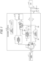
- FIG. 1 is a schematic configuration diagram of a measurement apparatus 10 according to the embodiment.
- the measurement apparatus 10 is an apparatus that can measure a resistance component leakage current of a live wire.
- FIG. 1 illustrates how the measurement apparatus 10 measures a resistance component leakage current of a wire 5 connecting between a distribution board 1 and a load 2.
- the wire 5 is a wire through which current is flowing, and thus is a live wire 5.
- FIG. 1 illustrates, as an example, the measurement apparatus 10 that is measuring the resistance component leakage current of the wire 5 connecting between the distribution board 1 to the load 2.
- the measurement apparatus 10 can measure a resistance component leakage current of any live wire, not limited to the wire 5.
- the wire 5 has a signal line 5a and a ground line 5b.
- the wire 5 may be, for example, a coaxial cable in which the ground line 5b is wound around the signal line 5a.
- a current I1 flows through the signal line 5a from the distribution board 1 to the load 2. Also, a current I2 flows through the ground line 5b from the load 2 to the distribution board 1. When no leakage current flows from the wire 5, the currents I1 and I2 are equal.
- the leakage current Io is a difference between the current I1 and the current I2, and is expressed by the following equation (1).
- Io I 1 ⁇ I 2
- the leakage current Io is the vector sum of a resistance component leakage current Ior flowing from the signal line 5a of the wire 5 to the ground through a resistor 4 and a capacitance component leakage current Ioc flowing from the signal line 5a of the wire 5 to the ground through a capacitor 3.
- the resistor 4 illustrated in FIG. 1 is not an image of a resistance element, but of a resistance component through which the resistance component leakage current Ior flows.
- the capacitor 3 illustrated in FIG. 1 is not an image of a capacitor element, but of a capacitance component through which the capacitance component leakage current Ioc flows.
- FIG. 2 is a vector diagram illustrating the relationship between the leakage current Io, the resistance component leakage current Ior, and the capacitance component leakage current Ioc.
- ⁇ is a phase angle between the leakage current Io flowing through the wire 5 and the voltage of the wire 5.
- the voltage of the wire 5" means a difference between the voltage of the signal line 5a and the voltage of the ground line 5b.
- the resistance component leakage current Ior is expressed by the following equation (2) based on the leakage current Io and the phase angle ⁇ .
- Ior Io ⁇ cos ⁇
- the measurement apparatus 10 has a magnetic core 11, a first coil L1, a second coil L2, a current measurement circuit 12, a voltage measurement circuit 13, a signal generator 14, a phase angle detection circuit 15, a controller 16, an input interface 17, a display 18, a first switch SW1, a second switch SW2, a third switch SW3.
- the magnetic core 11 can be disposed so as to surround the wire 5, which is a target of measurement of the resistance component leakage current.
- the magnetic core 11 may be in the shape of a ring, for example.
- the magnetic core 11 may be partially openable and closable. When the magnetic core 11 is partially openable and closeable, the magnetic core 11 can catch the wire 5.
- the first coil L1 is a coil wound around the magnetic core 11.
- the first coil L1 can detect a leakage current of the wire 5 caught by the magnetic core 11.
- the second coil L2 is a coil wound around the magnetic core 11.
- the second coil L2 is a coil used in a calibration operation in the measurement apparatus 10.
- a sinusoidal current flows through the second coil L2.
- the second coil L2 then generates, inside the magnetic core 11, a magnetic flux in response to the sinusoidal wave. Then, a current flows through the first coil L1, and the first coil L1 detects the current corresponding to the sinusoidal wave.
- the current measurement circuit 12 is connected to the first coil L1. To the current measurement circuit 12, the leakage current of the wire 5 detected by the first coil L1 is input. The current measurement circuit 12 can thereby measure the leakage current of the wire 5.
- the current measurement circuit 12 may include a current-to-voltage conversion circuit, an amplification circuit, and the like.
- the current measurement circuit 12 outputs a signal corresponding to the measured leakage current of the wire 5 to the phase angle detection circuit 15 and the controller 16.
- the current measurement circuit 12 may output the signal corresponding to the measured leakage current of the wire 5, as a current or as a voltage.
- the voltage measurement circuit 13 can be connected to the signal line 5a and the ground line 5b of the wire 5.
- the voltage measurement circuit 13 measures, as the voltage of the wire 5, the difference between the voltage of the signal line 5a and the voltage of the ground line 5b.
- the voltage measurement circuit 13 may include a differential amplifier circuit or the like.
- the voltage measurement circuit 13 outputs a signal corresponding to the measured voltage of the wire 5 to the phase angle detection circuit 15 via the third switch SW3.
- the signal generator 14 is a signal generator of any configuration that can output two synchronized sinusoidal waves.
- the signal generator 14 is connected to the second coil L2 via the first switch SW1.
- the signal generator 14 is connected to the phase angle detection circuit 15 via the second switch SW2.
- the signal generator 14 outputs synchronized sinusoidal waves to the second coil L2 and the phase angle detection circuit 15 during the calibration operation in the measurement apparatus 10.
- the phase angle detection circuit 15 is a circuit that can detect a phase angle between two input signals.
- the phase angle detection circuit 15 detects a phase angle between the leakage current measured by the current measurement circuit 12 and the voltage measured by the voltage measurement circuit 13.
- the phase angle detection circuit 15 outputs the detected phase angle to the controller 16.
- the phase angle detection circuit 15 detects a phase angle for calibration between a current measured by the current measurement circuit 12 when the signal generator 14 is outputting the sinusoidal waves, and the sinusoidal wave input from the signal generator 14.
- the phase angle between the current measured by the current measurement circuit 12 when the signal generator 14 is outputting the sinusoidal waves, and the sinusoidal wave input from the signal generator 14 may be referred to as "calibration phase angle”.
- the phase angle detection circuit 15 outputs the detected calibration phase angle to the controller 16.
- the controller 16 controls the entire measurement apparatus 10 and each block of the measurement apparatus 10.
- the controller 16 includes at least one processor, at least one dedicated circuit, or a combination thereof.
- the processor is a general purpose processor, such as a central processing unit (CPU) or a graphics processing unit (GPU), or a dedicated processor specialized for particular processing.
- the dedicated circuit is, for example, a field-programmable gate array (FPGA) or an application specific integrated circuit (ASIC).
- the input interface 17 includes an interface that can accept operations from a user.
- the input interface 17 may include, for example, buttons or the like.
- the display 18 can display various types of data.
- the display 18 may include, for example, a liquid crystal display (LCD), an organic electroluminescent (EL) display, or the like.
- the first switch SW1 is connected between the signal generator 14 and the second coil L2.
- the first switch SW1 can turn on/off the connection between the signal generator 14 and the second coil L2 according to a command of the controller 16.
- the first switch SW1 may be a switch of any configuration capable of switching the electrical connection on and off.
- the second switch SW2 is connected between the signal generator 14 and the phase angle detection circuit 15.
- the second switch SW2 can turn on/off the connection between the signal generator 14 and the phase angle detection circuit 15 according to a command of the controller 16.
- the second switch SW2 may be a switch of any configuration capable of switching the electrical connection on and off.
- the third switch SW3 is connected between the voltage measurement circuit 13 and the phase angle detection circuit 15.
- the third switch SW3 can turn on/off the connection between the voltage measurement circuit 13 and the phase angle detection circuit 15 according to a command of the controller 16.
- the third switch SW3 may be a switch of any configuration capable of switching the electrical connection on and off.
- the measurement apparatus 10 performs the calibration operation and the measurement operation when measuring a resistance component leakage current.
- the calibration operation and the measurement operation will be described in turn.
- the measurement apparatus 10 can correct a phase advance or delay caused by the magnetic core 11, the first coil L1, and the current measurement circuit 12.
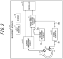
- FIG. 3 is a diagram illustrating the measurement apparatus 10 during the calibration operation. In the calibration operation, the magnetic core 11 does not catch the wire 5. Therefore, FIG. 3 does not illustrate the distribution board 1, the wire 5, the load 2, the capacitor 3, and the resistor 4.
- the input interface 17 can accept, from the user, an operation to start the calibration operation.
- the controller 16 starts the calibration operation when the input interface 17 accepts, from the user, the operation to start the calibration operation.
- the controller 16 turns on the first switch SW1 and the second switch SW2. The controller 16 also turns off the third switch SW3.
- the controller 16 then controls the signal generator 14 to generate two synchronized sinusoidal waves.
- the signal generator 14 outputs one of the sinusoidal waves to the second coil L2 via the first switch SW1.
- the signal generator 14 also outputs the other of the sinusoidal waves to the phase angle detection circuit 15 via the second switch SW2.
- the frequency of the sinusoidal waves output by the signal generator 14 may be the same as a measurement target frequency of the resistance component leakage current. For example, when the measurement target frequency is 50 Hz, the frequency of the sinusoidal waves output by the signal generator 14 may be 50 Hz. For example, when the measurement target frequency is 60 Hz, the frequency of the sinusoidal waves output by the signal generator 14 may be 60 Hz.
- the first coil L1 detects a current corresponding to the sinusoidal wave input to the second coil L2.
- the current measurement circuit 12 measures a current flowing through the first coil L1, and outputs a signal corresponding to the measured current to the phase angle detection circuit 15.
- the phase angle detection circuit 15 detects a calibration phase angle between the current measured by the current measurement circuit 12 when the signal generator 14 is outputting the sinusoidal waves, and the sinusoidal wave input from the signal generator 14.
- the calibration phase angle detected by the phase angle detection circuit 15 is a phase angle caused by the magnetic core 11, the first coil L1, and the current measurement circuit 12.
- the phase angle detection circuit 15 outputs the detected calibration phase angle to the controller 16.
- the controller 16 holds the calibration phase angle.
- the measurement apparatus 10 After the calibration operation is completed and the controller 16 holds the calibration phase angle, the measurement apparatus 10 can perform the measurement operation.
- FIG. 1 is a diagram illustrating the measurement apparatus 10 during the measurement operation.
- the magnetic core 11 is catching the wire 5, which is a target of measurement of the resistance component leakage current.
- a current is flowing through the wire 5, so the wire 5 is a live wire.
- the controller 16 turns off the first switch SW1 and the second switch SW2.
- the controller 16 turns on the third switch SW3.
- the controller 16 controls the signal generator 14 to output no sinusoidal waves.
- the first coil L1 detects a leakage current of the wire 5 caught by the magnetic core 11.
- the leakage current of the wire 5 detected by the first coil L1 is input.
- the current measurement circuit 12 thereby measures the leakage current of the wire 5.
- the current measurement circuit 12 outputs a signal corresponding to the measured leakage current to the phase angle detection circuit 15.
- the voltage measurement circuit 13 measures, as the voltage of the wire 5, a difference between the voltage of the signal line 5a and the voltage of the ground line 5b.
- the voltage measurement circuit 13 outputs a signal corresponding to the measured voltage of the wire 5 to the phase angle detection circuit 15 via the third switch SW3.
- the phase angle detection circuit 15 detects a phase angle between the leakage current measured by the current measurement circuit 12 and the voltage of the wire 5 measured by the voltage measurement circuit 13.
- the phase angle detection circuit 15 outputs the detected phase angle to the controller 16.
- the controller 16 calculates a corrected phase angle ⁇ , as in the following equation (3), based on the phase angle ⁇ 1 acquired from the phase angle detection circuit 15 in the measurement operation and the calibration phase angle ⁇ 2 acquired from the phase angle detection circuit 15 in the calibration operation.
- ⁇ ⁇ 1 ⁇ ⁇ 2
- the controller 16 can calculate the corrected phase angle ⁇ that corrects the phase advance or delay caused by the magnetic core 11, the first coil L1, and the current measurement circuit 12.
- the controller 16 calculates a resistance component leakage current Ior, as in the following equation (4), based on the leakage current Io measured by the current measurement circuit 12 and the corrected phase angle ⁇ calculated by the above equation (3).
- Ior Io ⁇ cos ⁇
- the controller 16 displays the calculated resistance component leakage current Ior on the display 18.
- the measurement apparatus 10 can measure a phase angle with high accuracy when measuring a resistance component leakage current. More specifically, the measurement apparatus 10 includes the signal generator 14 that can output sinusoidal waves to the second coil L2 and the phase angle detection circuit 15, and the phase angle detection circuit 15 can detect a calibration phase angle between a current measured by the current measurement circuit 12 when the signal generator 14 is outputting the sinusoidal waves, and the sinusoidal wave input from the signal generator 14. The controller 16 then calculates a corrected phase angle based on a phase angle between a leakage current and a voltage and the calibration phase angle, and calculates a resistance component leakage current based on the leakage current and the corrected phase angle.
- the measurement apparatus 10 can calculate the corrected phase angle that corrects a phase advance or delay caused by the magnetic core 11, the first coil L1, and the current measurement circuit 12. Therefore, the measurement apparatus 10 can measure the phase angle with high accuracy when measuring the resistance component leakage current.
- the measurement apparatus 10 eliminates the need for adjusting or correcting a phase advance or delay during maintenance or other operations because a calibration phase angle can be calculated automatically. Therefore, a burden on an operator can be reduced. In addition, it is unnecessary to set up equipment for calibration.
- FIG. 4 is a diagram illustrating the schematic configuration of a measurement apparatus 10a according to a variation.
- the measurement apparatus 10a according to the variation will be described with reference to FIG. 4 .
- the measurement apparatus 10a according to the variation operates differently from the measurement apparatus 10 illustrated in FIG. 1 in that the calibration operation and the measurement operation are performed simultaneously.
- the measurement apparatus 10a according to the variation performs the calibration operation and the measurement operation simultaneously. Therefore, the measurement apparatus 10a according to the variation operates with all of the first switch SW1, the second switch SW2, and the third switch SW3 turned on, as illustrated in FIG. 4 .
- the measurement apparatus 10a since the measurement apparatus 10a operates with all of the first switch SW1, the second switch SW2, and the third switch SW3 turned on, the measurement apparatus 10a according to the variation may not include the first switch SW1, the second switch SW2, and the third switch SW3. In this case, the first switch SW1, the second switch SW2, and the third switch SW3 may be shorted.
- the signal generator 14 of the measurement apparatus 10a outputs sinusoidal waves of a frequency different from a measurement target frequency of a resistance component leakage current. For example, when the measurement target frequency of the resistance component leakage current is 50 Hz, the signal generator 14 outputs the sinusoidal waves at a frequency different from 50 Hz.
- the measurement apparatus 10a can perform the calibration operation and the measurement operation simultaneously.
- Freq-meas represents the measurement target frequency
- Freq_cal represents the frequency of the sinusoidal waves for the calibration operation output by the signal generator 14.
- the phase angle detection circuit 15 detects, as a calibration frequency phase angle, a phase angle between a current at a frequency of Freq_cal measured by the current measurement circuit 12 and the sinusoidal wave at the frequency of Freq_cal input from the signal generator 14.
- the phase angle detection circuit 15 outputs the detected calibration frequency phase angle to the controller 16.
- the controller 16 calculates a calibration phase angle ⁇ 2 based on the calibration frequency phase angle ⁇ cal acquired from the phase angle detection circuit 15, as in the following equation (5).
- ⁇ 2 1 1 ⁇ cal ⁇ Freq _ meas Freq _ cal
- the phase angle detection circuit 15 also detects a phase angle ⁇ 1 between a leakage current at a frequency of Freq_meas measured by the current measurement circuit 12 and a voltage at the frequency of Freq_meas in the wire 5 measured by the voltage measurement circuit 13.
- the phase angle detection circuit 15 outputs the detected phase angle ⁇ 1 to the controller 16.
- the controller 16 calculates, as in the above equation (3), a corrected phase angle ⁇ based on the phase angle ⁇ 1 acquired from the phase angle detection circuit 15 and the calibration phase angle ⁇ 2 calculated based on the above equation (5).
- the signal generator 14 of the measurement apparatus 10a may output sinusoidal waves at one frequency different from the measurement target frequency of the resistance component leakage current as described above, or may output sinusoidal waves at two frequencies different from the measurement target frequency of the resistance component leakage current. Operations when the signal generator 14 outputs sinusoidal waves at two frequencies different from the measurement target frequency of the resistance component leakage current will be hereinafter described.
- Freq_cal1 represents one of the frequencies of the sinusoidal waves for the calibration operation output by the signal generator 14, and Freq_cal2 represents the other of the frequencies of the sinusoidal waves for the calibration operation output by the signal generator 14.
- Freq_cal1 is a frequency lower than Freq_meas, and Freq_cal2 is a frequency higher than Freq_meas.
- the phase angle detection circuit 15 detects, as a first calibration frequency phase angle, a phase angle between a current at a frequency of Freq_cal1 measured by the current measurement circuit 12 and the sinusoidal wave at the frequency of Freq_cal1 input from the signal generator 14.
- the phase angle detection circuit 15 detects, as a second calibration frequency phase angle, a phase angle between a current at a frequency of Freq_cal2 measured by the current measurement circuit 12 and the sinusoidal wave at the frequency of Freq_cal2 input from the signal generator 14.
- the phase angle detection circuit 15 outputs the detected first and second calibration frequency phase angles to the controller 16.
- the controller 16 calculates a calibration phase angle ⁇ 2 based on the first calibration frequency phase angle ⁇ cal1 and the second calibration frequency phase angle ⁇ cal2 acquired from the phase angle detection circuit 15, as in equations (6) to (8) below.
- A 1 ⁇ cal 2 ⁇ 1 ⁇ cal 1 Freq _ cal 2 ⁇ Freq _ cal 1
- B 1 ⁇ cal 1 ⁇ A ⁇ Freq _ cal 1
- ⁇ 2 1 A ⁇ Freq _ meas + B
- the phase angle detection circuit 15 also detects a phase angle ⁇ 1 between a leakage current at a frequency of Freq_meas measured by the current measurement circuit 12 and a voltage at the frequency of Freq_meas in the wire 5 measured by the voltage measurement circuit 13.
- the phase angle detection circuit 15 outputs the detected phase angle ⁇ 1 to the controller 16.
- the controller 16 calculates, as in the above equation (3), a corrected phase angle ⁇ based on the phase angle ⁇ 1 acquired from the phase angle detection circuit 15 and the calibration phase angle ⁇ 2 calculated based on the equations (6) to (8) above.
- the measurement apparatus 10a can calculate a corrected phase angle ⁇ with high accuracy over a wide frequency range, compared to a case in which the signal generator 14 outputs the sinusoidal waves at one frequency different from the measurement target frequency.
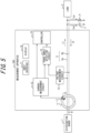
- FIG. 5 is a schematic configuration diagram of a measurement apparatus 200 according to a comparative example.
- the measurement apparatus 200 includes a magnetic core 11, a first coil L1, a current measurement circuit 12, a voltage measurement circuit 13, a phase angle detection circuit 15, a controller 16, an input interface 17, and a display 18.
- the measurement apparatus 200 according to the comparative example differs from the measurement apparatus 10 according to the embodiment illustrated in FIG. 1 in that the measurement apparatus 200 does not have the second coil L2, the signal generator 14, the first switch SW1, the second switch SW2, and the third switch SW3.
- the measurement apparatus 200 according to the comparative example does not have the second coil L2 and the signal generator 14, and therefore cannot perform the calibration operation, which the measurement apparatus 10 illustrated in FIG. 1 can perform.
- the measurement apparatus 200 according to the comparative example cannot correct a phase advance or delay caused by the magnetic core 11, the first coil L1, and the current measurement circuit 12 by the calibration operation. Therefore, the measurement apparatus 200 according to the comparative example cannot measure a phase angle with high accuracy when measuring a resistance component leakage current.
- each of the components described above are not limited to those illustrated in the above description and drawings.
- the disposition, number, and the like of each of the components may be arbitrarily configured as long as the function thereof can be realized.
- the above embodiment describes the measurement apparatus 10 that can correct a phase angle when measuring a resistance component leakage current.
- the above technology for correcting a phase angle can also be applied to other apparatuses that measure a phase angle.
- it is important for clamp power meters to measure a phase angle with high accuracy and the above technology for correcting a phase angle is also applicable to the clamp power meters.
- the clamp power meter can measure a phase angle with high accuracy, and therefore can perform power measurement with high accuracy.
Landscapes
- Physics & Mathematics (AREA)
- General Physics & Mathematics (AREA)
- Engineering & Computer Science (AREA)
- Power Engineering (AREA)
- Testing Of Short-Circuits, Discontinuities, Leakage, Or Incorrect Line Connections (AREA)
Abstract
A phase angle is measured accurately when a resistance component leakage current is measured. A measurement apparatus 10 according to the present disclosure includes a magnetic core 11, first and second coils L1 and L2 wound around the magnetic core 11, a current measurement circuit 12, a voltage measurement circuit 13, a phase angle detection circuit 15, a signal generator 14 that can output sinusoidal waves to the second coil 12 and the phase angle detection circuit 15, and a controller 16. The phase angle detection circuit 15 can detect a calibration phase angle between a current measured by the current measurement circuit 12 when the signal generator 14 is outputting the sinusoidal waves, and one of the sinusoidal waves input from the signal generator 14. The controller 16 calculates a corrected phase angle based on a phase angle and the calibration phase angle, and calculates a resistance component leakage current based on a leakage current and the corrected phase angle.
Description
- This application claims priority to
Japanese Patent Application No. 2023-078038, filed on May 10, 2023 - The present disclosure relates to a measurement apparatus and a measurement method.
- Technology for measuring leakage current in live wires is known. The live wires are wires through which current is flowing. The leakage current is also referred to as "Io".
- The leakage current has resistance component leakage current and capacitance component leakage current. The resistance component leakage current is also referred to as "Ior". The capacitance component leakage current is also referred to as "loc".
- The leakage current (Io) is the vector sum of the resistance component leakage current (Ior) and the capacitance component leakage current (Ioc). When θ represents a phase angle between the leakage current of a wire and the voltage of the wire, the resistance component leakage current (Ior) is expressed by the following equation.

- Flowing resistance component leakage current generates heat and thus can cause fires and other problems. Therefore, it is important to measure the resistance component leakage current with high accuracy.
- For example, Patent Literature (PTL) 1 discloses a detection apparatus that can measure a resistance component leakage current.
- PTL 1:
JP 2023-21267 A - A resistance component leakage current is calculated based on a leakage current and a phase angle, as in the above equation. Accordingly, in order to measure the resistance component leakage current with high accuracy, it is necessary to measure not only the leakage current accurately but also the phase angle accurately.
- In the normal measurement of the leakage current, a phase advance or delay occurs in a magnetic core, a current measurement circuit, and the like for measuring the leakage current. Therefore, it is necessary to adjust or correct the phase advance or delay during manufacturing, maintenance, or the like.
- However, the phase advance or delay may significantly vary due to degradation of an apparatus and variations in environmental temperature. Therefore, when the resistance component leakage current is actually measured, the phase advance or delay may vary significantly since the adjustment or correction has been made, making it difficult to measure the phase angle with high accuracy.
- It would be helpful to provide a measurement apparatus and a measurement method that can measure a phase angle with high accuracy when a resistance component leakage current is measured.
- A measurement apparatus according to some embodiments is a measurement apparatus configured to be able to measure a resistance component leakage current, the measurement apparatus including:
- a magnetic core capable of being disposed so as to surround a wire;
- first and second coils wound around the magnetic core;
- a current measurement circuit connected to the first coil, the current measurement circuit configured to be able to measure a leakage current of the wire;
- a voltage measurement circuit configured to be able to measure a voltage of the wire;
- a phase angle detection circuit configured to be able to detect a phase angle between the leakage current and the voltage;
- a signal generator configured to be able to output sinusoidal waves to the second coil and the phase angle detection circuit; and
- a controller,
- wherein
- the phase angle detection circuit is configured to be able to detect a calibration phase angle between a current measured by the current measurement circuit when the signal generator is outputting the sinusoidal waves, and one of the sinusoidal waves input from the signal generator, and
- the controller is configured to:
- calculate a corrected phase angle based on the phase angle and the calibration phase angle; and
- calculate the resistance component leakage current based on the leakage current and the corrected phase angle. Such a measurement apparatus can measure the phase angle with high accuracy when measuring the resistance component leakage current.
- In the measurement apparatus according to an embodiment, the controller is configured to calculate the corrected phase angle based on the following equation (1):

- In the measurement apparatus according to an embodiment, the controller is configured to calculate the resistance component leakage current based on the following equation (2):

- The measurement apparatus according to an embodiment may further include an input interface configured to be able to accept an operation from a user,
wherein when the input interface accepts, from the user, the operation to start a calibration operation, the controller may control the signal generator to output the sinusoidal waves and may detect the calibration phase angle. This allows the calibration operation to be started in response to the operation from the user. - The measurement apparatus according to an embodiment may further include a display,
wherein the controller may be configured to control the display to display the calculated resistance component leakage current. This allows the user to check the resistance component leakage current by display on the display. - In the measurement apparatus according to an embodiment,
- the signal generator may be configured to output the sinusoidal waves at one or more frequencies different from a measurement target frequency of the resistance component leakage current, and
- the controller may be configured to perform detection of the calibration phase angle and calculation of the resistance component leakage current simultaneously. This allows the calibration operation and a measurement operation to be performed simultaneously.
- In the measurement apparatus according to an embodiment,
- the signal generator may be configured to output the sinusoidal waves at one frequency different from the measurement target frequency of the resistance component leakage current, and
- the controller may be configured to calculate the calibration phase angle at the measurement target frequency of the resistance component leakage current, based on the calibration phase angle detected when the signal generator is outputting the sinusoidal waves at the one frequency different from the measurement target frequency of the resistance component leakage current. This allows the calibration operation and the measurement operation to be performed simultaneously.
- In the measurement apparatus according to an embodiment,
- the signal generator may be configured to output the sinusoidal waves at two frequencies different from the measurement target frequency of the resistance component leakage current, and
- the controller may be configured to calculate the calibration phase angle at the measurement target frequency of the resistance component leakage current, based on the calibration phase angle detected when the signal generator is outputting the sinusoidal waves at the two frequencies different from the measurement target frequency of the resistance component leakage current. This allows the calibration operation and the measurement operation to be performed simultaneously.
- In the measurement apparatus according to an embodiment, one of the two frequencies may be higher than the measurement target frequency, and the other of the two frequencies may be lower than the measurement target frequency. This allows calculation of the calibration phase angle with high accuracy.
- A measurement method according to some embodiments is a measurement method by a measurement apparatus configured to be able to measure a resistance component leakage current, the measurement apparatus including a magnetic core capable of being disposed so as to surround a wire, first and second coils wound around the magnetic core, a current measurement circuit connected to the first coil, the current measurement circuit configured to be able to measure a leakage current of the wire, a voltage measurement circuit configured to be able to measure a voltage of the wire, a phase angle detection circuit configured to be able to detect a phase angle between the leakage current and the voltage, and a signal generator configured to be able to output sinusoidal waves to the second coil and the phase angle detection circuit, the measurement method including:
- detecting, by the phase angle detection circuit, a calibration phase angle between a current measured by the current measurement circuit when the signal generator is outputting the sinusoidal waves, and one of the sinusoidal waves input from the signal generator;
- calculating a corrected phase angle based on the phase angle and the calibration phase angle; and
- calculating the resistance component leakage current based on the leakage current and the corrected phase angle. Such a measurement method can measure the phase angle with high accuracy when measuring the resistance component leakage current.
- According to the present disclosure, it is possible to provide a measurement apparatus and a measurement method that can measure a phase angle with high accuracy when a resistance component leakage current is measured.
- In the accompanying drawings:
-
FIG. 1 is a schematic configuration diagram of a measurement apparatus according to an embodiment; -
FIG. 2 is a vector diagram illustrating the relationship between a leakage current Io, a resistance component leakage current Ior, and a capacitance component leakage current Ioc; -
FIG. 3 is a diagram illustrating the measurement apparatus according to the embodiment during a calibration operation; -
FIG. 4 is a schematic configuration diagram of a measurement apparatus according to a variation; and -
FIG. 5 is a schematic configuration diagram of a measurement apparatus according to a comparative example. - An embodiment of the present disclosure will be described below with reference to the drawings.
-
FIG. 1 is a schematic configuration diagram of ameasurement apparatus 10 according to the embodiment. - The
measurement apparatus 10 is an apparatus that can measure a resistance component leakage current of a live wire.FIG. 1 illustrates how themeasurement apparatus 10 measures a resistance component leakage current of awire 5 connecting between a distribution board 1 and aload 2. Thewire 5 is a wire through which current is flowing, and thus is alive wire 5. -
FIG. 1 illustrates, as an example, themeasurement apparatus 10 that is measuring the resistance component leakage current of thewire 5 connecting between the distribution board 1 to theload 2. Themeasurement apparatus 10 can measure a resistance component leakage current of any live wire, not limited to thewire 5. - The
wire 5 has asignal line 5a and aground line 5b. Thewire 5 may be, for example, a coaxial cable in which theground line 5b is wound around thesignal line 5a. - In the example illustrated in
FIG. 1 , a current I1 flows through thesignal line 5a from the distribution board 1 to theload 2. Also, a current I2 flows through theground line 5b from theload 2 to the distribution board 1. When no leakage current flows from thewire 5, the currents I1 and I2 are equal. - When a leakage current flows from the
wire 5, the leakage current Io is a difference between the current I1 and the current I2, and is expressed by the following equation (1).
- The leakage current Io is the vector sum of a resistance component leakage current Ior flowing from the
signal line 5a of thewire 5 to the ground through a resistor 4 and a capacitance component leakage current Ioc flowing from thesignal line 5a of thewire 5 to the ground through acapacitor 3. - The resistor 4 illustrated in
FIG. 1 is not an image of a resistance element, but of a resistance component through which the resistance component leakage current Ior flows. Thecapacitor 3 illustrated inFIG. 1 is not an image of a capacitor element, but of a capacitance component through which the capacitance component leakage current Ioc flows. -
FIG. 2 is a vector diagram illustrating the relationship between the leakage current Io, the resistance component leakage current Ior, and the capacitance component leakage current Ioc. InFIG. 2 , θ is a phase angle between the leakage current Io flowing through thewire 5 and the voltage of thewire 5. In this embodiment, "the voltage of thewire 5" means a difference between the voltage of thesignal line 5a and the voltage of theground line 5b. - As illustrated in
FIG. 2 , the resistance component leakage current Ior is expressed by the following equation (2) based on the leakage current Io and the phase angle θ.
- With reference again to
FIG. 1 , the outline of the configuration and functions of themeasurement apparatus 10 will be described. - The
measurement apparatus 10 has amagnetic core 11, a first coil L1, a second coil L2, acurrent measurement circuit 12, avoltage measurement circuit 13, asignal generator 14, a phaseangle detection circuit 15, acontroller 16, aninput interface 17, adisplay 18, a first switch SW1, a second switch SW2, a third switch SW3. - The
magnetic core 11 can be disposed so as to surround thewire 5, which is a target of measurement of the resistance component leakage current. Themagnetic core 11 may be in the shape of a ring, for example. Themagnetic core 11 may be partially openable and closable. When themagnetic core 11 is partially openable and closeable, themagnetic core 11 can catch thewire 5. - The first coil L1 is a coil wound around the
magnetic core 11. The first coil L1 can detect a leakage current of thewire 5 caught by themagnetic core 11. - The second coil L2 is a coil wound around the
magnetic core 11. The second coil L2 is a coil used in a calibration operation in themeasurement apparatus 10. - When a sinusoidal wave is input from the
signal generator 14 to the second coil L2 during the calibration operation, a sinusoidal current flows through the second coil L2. The second coil L2 then generates, inside themagnetic core 11, a magnetic flux in response to the sinusoidal wave. Then, a current flows through the first coil L1, and the first coil L1 detects the current corresponding to the sinusoidal wave. - The
current measurement circuit 12 is connected to the first coil L1. To thecurrent measurement circuit 12, the leakage current of thewire 5 detected by the first coil L1 is input. Thecurrent measurement circuit 12 can thereby measure the leakage current of thewire 5. - The
current measurement circuit 12 may include a current-to-voltage conversion circuit, an amplification circuit, and the like. Thecurrent measurement circuit 12 outputs a signal corresponding to the measured leakage current of thewire 5 to the phaseangle detection circuit 15 and thecontroller 16. Thecurrent measurement circuit 12 may output the signal corresponding to the measured leakage current of thewire 5, as a current or as a voltage. - The
voltage measurement circuit 13 can be connected to thesignal line 5a and theground line 5b of thewire 5. Thevoltage measurement circuit 13 measures, as the voltage of thewire 5, the difference between the voltage of thesignal line 5a and the voltage of theground line 5b. Thevoltage measurement circuit 13 may include a differential amplifier circuit or the like. Thevoltage measurement circuit 13 outputs a signal corresponding to the measured voltage of thewire 5 to the phaseangle detection circuit 15 via the third switch SW3. - The
signal generator 14 is a signal generator of any configuration that can output two synchronized sinusoidal waves. Thesignal generator 14 is connected to the second coil L2 via the first switch SW1. Thesignal generator 14 is connected to the phaseangle detection circuit 15 via the second switch SW2. - The
signal generator 14 outputs synchronized sinusoidal waves to the second coil L2 and the phaseangle detection circuit 15 during the calibration operation in themeasurement apparatus 10. - The phase
angle detection circuit 15 is a circuit that can detect a phase angle between two input signals. - When the
measurement apparatus 10 performs a measurement operation, the phaseangle detection circuit 15 detects a phase angle between the leakage current measured by thecurrent measurement circuit 12 and the voltage measured by thevoltage measurement circuit 13. The phaseangle detection circuit 15 outputs the detected phase angle to thecontroller 16. - When the
measurement apparatus 10 performs the calibration operation, the phaseangle detection circuit 15 detects a phase angle for calibration between a current measured by thecurrent measurement circuit 12 when thesignal generator 14 is outputting the sinusoidal waves, and the sinusoidal wave input from thesignal generator 14. In this embodiment, the phase angle between the current measured by thecurrent measurement circuit 12 when thesignal generator 14 is outputting the sinusoidal waves, and the sinusoidal wave input from thesignal generator 14 may be referred to as "calibration phase angle". The phaseangle detection circuit 15 outputs the detected calibration phase angle to thecontroller 16. - The
controller 16 controls theentire measurement apparatus 10 and each block of themeasurement apparatus 10. Thecontroller 16 includes at least one processor, at least one dedicated circuit, or a combination thereof. The processor is a general purpose processor, such as a central processing unit (CPU) or a graphics processing unit (GPU), or a dedicated processor specialized for particular processing. The dedicated circuit is, for example, a field-programmable gate array (FPGA) or an application specific integrated circuit (ASIC). - The details of operations of the
controller 16 will be described below. - The
input interface 17 includes an interface that can accept operations from a user. Theinput interface 17 may include, for example, buttons or the like. - The
display 18 can display various types of data. Thedisplay 18 may include, for example, a liquid crystal display (LCD), an organic electroluminescent (EL) display, or the like. - The first switch SW1 is connected between the
signal generator 14 and the second coil L2. The first switch SW1 can turn on/off the connection between thesignal generator 14 and the second coil L2 according to a command of thecontroller 16. The first switch SW1 may be a switch of any configuration capable of switching the electrical connection on and off. - The second switch SW2 is connected between the
signal generator 14 and the phaseangle detection circuit 15. The second switch SW2 can turn on/off the connection between thesignal generator 14 and the phaseangle detection circuit 15 according to a command of thecontroller 16. The second switch SW2 may be a switch of any configuration capable of switching the electrical connection on and off. - The third switch SW3 is connected between the
voltage measurement circuit 13 and the phaseangle detection circuit 15. The third switch SW3 can turn on/off the connection between thevoltage measurement circuit 13 and the phaseangle detection circuit 15 according to a command of thecontroller 16. The third switch SW3 may be a switch of any configuration capable of switching the electrical connection on and off. - The
measurement apparatus 10 performs the calibration operation and the measurement operation when measuring a resistance component leakage current. The calibration operation and the measurement operation will be described in turn. - First, the calibration operation of the
measurement apparatus 10 will be described. By performing the calibration operation immediately before performing the measurement operation, themeasurement apparatus 10 can correct a phase advance or delay caused by themagnetic core 11, the first coil L1, and thecurrent measurement circuit 12. -
FIG. 3 is a diagram illustrating themeasurement apparatus 10 during the calibration operation. In the calibration operation, themagnetic core 11 does not catch thewire 5. Therefore,FIG. 3 does not illustrate the distribution board 1, thewire 5, theload 2, thecapacitor 3, and the resistor 4. - The
input interface 17 can accept, from the user, an operation to start the calibration operation. Thecontroller 16 starts the calibration operation when theinput interface 17 accepts, from the user, the operation to start the calibration operation. - When the calibration operation starts, the
controller 16 turns on the first switch SW1 and the second switch SW2. Thecontroller 16 also turns off the third switch SW3. - The
controller 16 then controls thesignal generator 14 to generate two synchronized sinusoidal waves. Thesignal generator 14 outputs one of the sinusoidal waves to the second coil L2 via the first switch SW1. Thesignal generator 14 also outputs the other of the sinusoidal waves to the phaseangle detection circuit 15 via the second switch SW2. - The frequency of the sinusoidal waves output by the
signal generator 14 may be the same as a measurement target frequency of the resistance component leakage current. For example, when the measurement target frequency is 50 Hz, the frequency of the sinusoidal waves output by thesignal generator 14 may be 50 Hz. For example, when the measurement target frequency is 60 Hz, the frequency of the sinusoidal waves output by thesignal generator 14 may be 60 Hz. - When one of the sinusoidal waves is input to the second coil L2 from the
signal generator 14, the first coil L1 detects a current corresponding to the sinusoidal wave input to the second coil L2. Thecurrent measurement circuit 12 measures a current flowing through the first coil L1, and outputs a signal corresponding to the measured current to the phaseangle detection circuit 15. - The phase
angle detection circuit 15 detects a calibration phase angle between the current measured by thecurrent measurement circuit 12 when thesignal generator 14 is outputting the sinusoidal waves, and the sinusoidal wave input from thesignal generator 14. The calibration phase angle detected by the phaseangle detection circuit 15 is a phase angle caused by themagnetic core 11, the first coil L1, and thecurrent measurement circuit 12. - The phase
angle detection circuit 15 outputs the detected calibration phase angle to thecontroller 16. Thecontroller 16 holds the calibration phase angle. - The measurement operation of the
measurement apparatus 10 will be subsequently described. After the calibration operation is completed and thecontroller 16 holds the calibration phase angle, themeasurement apparatus 10 can perform the measurement operation. -
FIG. 1 is a diagram illustrating themeasurement apparatus 10 during the measurement operation. In the measurement operation, themagnetic core 11 is catching thewire 5, which is a target of measurement of the resistance component leakage current. At this time, a current is flowing through thewire 5, so thewire 5 is a live wire. - When the measurement operation is started, the
controller 16 turns off the first switch SW1 and the second switch SW2. Thecontroller 16 turns on the third switch SW3. At this time, thecontroller 16 controls thesignal generator 14 to output no sinusoidal waves. - The first coil L1 detects a leakage current of the
wire 5 caught by themagnetic core 11. To thecurrent measurement circuit 12, the leakage current of thewire 5 detected by the first coil L1 is input. Thecurrent measurement circuit 12 thereby measures the leakage current of thewire 5. Thecurrent measurement circuit 12 outputs a signal corresponding to the measured leakage current to the phaseangle detection circuit 15. - The
voltage measurement circuit 13 measures, as the voltage of thewire 5, a difference between the voltage of thesignal line 5a and the voltage of theground line 5b. Thevoltage measurement circuit 13 outputs a signal corresponding to the measured voltage of thewire 5 to the phaseangle detection circuit 15 via the third switch SW3. - The phase
angle detection circuit 15 detects a phase angle between the leakage current measured by thecurrent measurement circuit 12 and the voltage of thewire 5 measured by thevoltage measurement circuit 13. - The phase
angle detection circuit 15 outputs the detected phase angle to thecontroller 16. - The
controller 16 calculates a corrected phase angle θ, as in the following equation (3), based on the phase angle Θ1 acquired from the phaseangle detection circuit 15 in the measurement operation and the calibration phase angle Θ2 acquired from the phaseangle detection circuit 15 in the calibration operation.
- As described above, by correcting the phase angle Θ1 acquired in the measurement operation based on the calibration phase angle Θ2 acquired in the calibration operation, the
controller 16 can calculate the corrected phase angle θ that corrects the phase advance or delay caused by themagnetic core 11, the first coil L1, and thecurrent measurement circuit 12. - The
controller 16 calculates a resistance component leakage current Ior, as in the following equation (4), based on the leakage current Io measured by thecurrent measurement circuit 12 and the corrected phase angle θ calculated by the above equation (3).
- The
controller 16 displays the calculated resistance component leakage current Ior on thedisplay 18. - As described above, the
measurement apparatus 10 according to the embodiment can measure a phase angle with high accuracy when measuring a resistance component leakage current. More specifically, themeasurement apparatus 10 includes thesignal generator 14 that can output sinusoidal waves to the second coil L2 and the phaseangle detection circuit 15, and the phaseangle detection circuit 15 can detect a calibration phase angle between a current measured by thecurrent measurement circuit 12 when thesignal generator 14 is outputting the sinusoidal waves, and the sinusoidal wave input from thesignal generator 14. Thecontroller 16 then calculates a corrected phase angle based on a phase angle between a leakage current and a voltage and the calibration phase angle, and calculates a resistance component leakage current based on the leakage current and the corrected phase angle. Thus, by detecting the calibration phase angle and calculating the corrected phase angle based on the phase angle and the calibration phase angle, themeasurement apparatus 10 can calculate the corrected phase angle that corrects a phase advance or delay caused by themagnetic core 11, the first coil L1, and thecurrent measurement circuit 12. Therefore, themeasurement apparatus 10 can measure the phase angle with high accuracy when measuring the resistance component leakage current. - The
measurement apparatus 10 according to the embodiment eliminates the need for adjusting or correcting a phase advance or delay during maintenance or other operations because a calibration phase angle can be calculated automatically. Therefore, a burden on an operator can be reduced. In addition, it is unnecessary to set up equipment for calibration. -
FIG. 4 is a diagram illustrating the schematic configuration of ameasurement apparatus 10a according to a variation. Themeasurement apparatus 10a according to the variation will be described with reference toFIG. 4 . - The
measurement apparatus 10a according to the variation operates differently from themeasurement apparatus 10 illustrated inFIG. 1 in that the calibration operation and the measurement operation are performed simultaneously. - Since the configuration of the
measurement apparatus 10a according to the variation is the same as that of themeasurement apparatus 10 illustrated inFIG. 1 , a description of the configuration of themeasurement apparatus 10a is omitted. - The
measurement apparatus 10a according to the variation performs the calibration operation and the measurement operation simultaneously. Therefore, themeasurement apparatus 10a according to the variation operates with all of the first switch SW1, the second switch SW2, and the third switch SW3 turned on, as illustrated inFIG. 4 . - Since the
measurement apparatus 10a operates with all of the first switch SW1, the second switch SW2, and the third switch SW3 turned on, themeasurement apparatus 10a according to the variation may not include the first switch SW1, the second switch SW2, and the third switch SW3. In this case, the first switch SW1, the second switch SW2, and the third switch SW3 may be shorted. - The
signal generator 14 of themeasurement apparatus 10a according to the variation outputs sinusoidal waves of a frequency different from a measurement target frequency of a resistance component leakage current. For example, when the measurement target frequency of the resistance component leakage current is 50 Hz, thesignal generator 14 outputs the sinusoidal waves at a frequency different from 50 Hz. - Thus, by setting the measurement target frequency of the resistance component leakage current and the frequency of the sinusoidal waves output by the
signal generator 14 to be different, themeasurement apparatus 10a can perform the calibration operation and the measurement operation simultaneously. - In the following description, Freq-meas represents the measurement target frequency, and Freq_cal represents the frequency of the sinusoidal waves for the calibration operation output by the
signal generator 14. - The phase
angle detection circuit 15 detects, as a calibration frequency phase angle, a phase angle between a current at a frequency of Freq_cal measured by thecurrent measurement circuit 12 and the sinusoidal wave at the frequency of Freq_cal input from thesignal generator 14. - The phase
angle detection circuit 15 outputs the detected calibration frequency phase angle to thecontroller 16. - The
controller 16 calculates a calibration phase angle Θ2 based on the calibration frequency phase angle θcal acquired from the phaseangle detection circuit 15, as in the following equation (5).
[Math. 1]
- The phase
angle detection circuit 15 also detects a phase angle Θ1 between a leakage current at a frequency of Freq_meas measured by thecurrent measurement circuit 12 and a voltage at the frequency of Freq_meas in thewire 5 measured by thevoltage measurement circuit 13. - The phase
angle detection circuit 15 outputs the detected phase angle Θ1 to thecontroller 16. - The
controller 16 calculates, as in the above equation (3), a corrected phase angle θ based on the phase angle θ1 acquired from the phaseangle detection circuit 15 and the calibration phase angle θ2 calculated based on the above equation (5). - The
signal generator 14 of themeasurement apparatus 10a according to the variation may output sinusoidal waves at one frequency different from the measurement target frequency of the resistance component leakage current as described above, or may output sinusoidal waves at two frequencies different from the measurement target frequency of the resistance component leakage current. Operations when thesignal generator 14 outputs sinusoidal waves at two frequencies different from the measurement target frequency of the resistance component leakage current will be hereinafter described. - In the following description, Freq_cal1 represents one of the frequencies of the sinusoidal waves for the calibration operation output by the
signal generator 14, and Freq_cal2 represents the other of the frequencies of the sinusoidal waves for the calibration operation output by thesignal generator 14. Freq_cal1 is a frequency lower than Freq_meas, and Freq_cal2 is a frequency higher than Freq_meas. - The phase
angle detection circuit 15 detects, as a first calibration frequency phase angle, a phase angle between a current at a frequency of Freq_cal1 measured by thecurrent measurement circuit 12 and the sinusoidal wave at the frequency of Freq_cal1 input from thesignal generator 14. - The phase
angle detection circuit 15 detects, as a second calibration frequency phase angle, a phase angle between a current at a frequency of Freq_cal2 measured by thecurrent measurement circuit 12 and the sinusoidal wave at the frequency of Freq_cal2 input from thesignal generator 14. - The phase
angle detection circuit 15 outputs the detected first and second calibration frequency phase angles to thecontroller 16. - The
controller 16 calculates a calibration phase angle Θ2 based on the first calibration frequency phase angle θcal1 and the second calibration frequency phase angle θcal2 acquired from the phaseangle detection circuit 15, as in equations (6) to (8) below.
[Math. 2]


- The phase
angle detection circuit 15 also detects a phase angle Θ1 between a leakage current at a frequency of Freq_meas measured by thecurrent measurement circuit 12 and a voltage at the frequency of Freq_meas in thewire 5 measured by thevoltage measurement circuit 13. - The phase
angle detection circuit 15 outputs the detected phase angle Θ1 to thecontroller 16. - The
controller 16 calculates, as in the above equation (3), a corrected phase angle θ based on the phase angle Θ1 acquired from the phaseangle detection circuit 15 and the calibration phase angle Θ2 calculated based on the equations (6) to (8) above. - As described above, since the
signal generator 14 outputs sinusoidal waves at two frequencies different from a measurement target frequency, themeasurement apparatus 10a according to the variation can calculate a corrected phase angle θ with high accuracy over a wide frequency range, compared to a case in which thesignal generator 14 outputs the sinusoidal waves at one frequency different from the measurement target frequency. -
FIG. 5 is a schematic configuration diagram of ameasurement apparatus 200 according to a comparative example. - The
measurement apparatus 200 according to the comparative example includes amagnetic core 11, a first coil L1, acurrent measurement circuit 12, avoltage measurement circuit 13, a phaseangle detection circuit 15, acontroller 16, aninput interface 17, and adisplay 18. - The
measurement apparatus 200 according to the comparative example differs from themeasurement apparatus 10 according to the embodiment illustrated inFIG. 1 in that themeasurement apparatus 200 does not have the second coil L2, thesignal generator 14, the first switch SW1, the second switch SW2, and the third switch SW3. - The
measurement apparatus 200 according to the comparative example does not have the second coil L2 and thesignal generator 14, and therefore cannot perform the calibration operation, which themeasurement apparatus 10 illustrated inFIG. 1 can perform. - Therefore, the
measurement apparatus 200 according to the comparative example cannot correct a phase advance or delay caused by themagnetic core 11, the first coil L1, and thecurrent measurement circuit 12 by the calibration operation. Therefore, themeasurement apparatus 200 according to the comparative example cannot measure a phase angle with high accuracy when measuring a resistance component leakage current. - It is obvious to a person skilled in the art that the present disclosure can be realized in predetermined forms other than the embodiment described above without departing from its spirit or its essential features. Accordingly, the preceding description is illustrative and not limiting. The scope of the disclosure is defined by the appended claims, not by the preceding description. Among all modifications, some modifications that are within the scope of equivalents are encompassed therein.
- For example, the disposition, number, and the like of each of the components described above are not limited to those illustrated in the above description and drawings. The disposition, number, and the like of each of the components may be arbitrarily configured as long as the function thereof can be realized.
- For example, the above embodiment describes the
measurement apparatus 10 that can correct a phase angle when measuring a resistance component leakage current. However, the above technology for correcting a phase angle can also be applied to other apparatuses that measure a phase angle. For example, it is important for clamp power meters to measure a phase angle with high accuracy, and the above technology for correcting a phase angle is also applicable to the clamp power meters. When the above technology for correcting a phase angle is implemented in a clamp power meter, the clamp power meter can measure a phase angle with high accuracy, and therefore can perform power measurement with high accuracy.
Claims (10)
- A measurement apparatus configured to be able to measure a resistance component leakage current, the measurement apparatus comprising:a magnetic core capable of being disposed so as to surround a wire;first and second coils wound around the magnetic core;a current measurement circuit connected to the first coil, the current measurement circuit configured to be able to measure a leakage current of the wire;a voltage measurement circuit configured to be able to measure a voltage of the wire;a phase angle detection circuit configured to be able to detect a phase angle between the leakage current and the voltage;a signal generator configured to be able to output sinusoidal waves to the second coil and the phase angle detection circuit; anda controller,whereinthe phase angle detection circuit is configured to be able to detect a calibration phase angle between a current measured by the current measurement circuit when the signal generator is outputting the sinusoidal waves, and one of the sinusoidal waves input from the signal generator, andthe controller is configured to:calculate a corrected phase angle based on the phase angle and the calibration phase angle; andcalculate the resistance component leakage current based on the leakage current and the corrected phase angle.
- The measurement apparatus according to claim 1, wherein the controller is configured to calculate the corrected phase angle based on a following equation (1):

- The measurement apparatus according to claim 2, wherein the controller is configured to calculate the resistance component leakage current based on a following equation (2):

- The measurement apparatus according to claim 1, further comprising an input interface configured to be able to accept an operation from a user,
wherein when the input interface accepts, from the user, the operation to start a calibration operation, the controller controls the signal generator to output the sinusoidal waves and detects the calibration phase angle. - The measurement apparatus according to claim 1, further comprising a display,
wherein the controller is configured to control the display to display the calculated resistance component leakage current. - The measurement apparatus according to claim 1, whereinthe signal generator is configured to output the sinusoidal waves at one or more frequencies different from a measurement target frequency of the resistance component leakage current, andthe controller is configured to perform detection of the calibration phase angle and calculation of the resistance component leakage current simultaneously.
- The measurement apparatus according to claim 6, whereinthe signal generator is configured to output the sinusoidal waves at one frequency different from the measurement target frequency of the resistance component leakage current, andthe controller is configured to calculate the calibration phase angle at the measurement target frequency of the resistance component leakage current, based on the calibration phase angle detected when the signal generator is outputting the sinusoidal waves at the one frequency different from the measurement target frequency of the resistance component leakage current.
- The measurement apparatus according to claim 6, whereinthe signal generator is configured to output the sinusoidal waves at two frequencies different from the measurement target frequency of the resistance component leakage current, andthe controller is configured to calculate the calibration phase angle at the measurement target frequency of the resistance component leakage current, based on the calibration phase angle detected when the signal generator is outputting the sinusoidal waves at the two frequencies different from the measurement target frequency of the resistance component leakage current.
- The measurement apparatus according to claim 8, wherein one of the two frequencies is higher than the measurement target frequency, and the other of the two frequencies is lower than the measurement target frequency.
- A measurement method by a measurement apparatus configured to be able to measure a resistance component leakage current, the measurement apparatus including a magnetic core capable of being disposed so as to surround a wire, first and second coils wound around the magnetic core, a current measurement circuit connected to the first coil, the current measurement circuit configured to be able to measure a leakage current of the wire, a voltage measurement circuit configured to be able to measure a voltage of the wire, a phase angle detection circuit configured to be able to detect a phase angle between the leakage current and the voltage, and a signal generator configured to be able to output sinusoidal waves to the second coil and the phase angle detection circuit, the measurement method comprising:detecting, by the phase angle detection circuit, a calibration phase angle between a current measured by the current measurement circuit when the signal generator is outputting the sinusoidal waves, and one of the sinusoidal waves input from the signal generator;calculating a corrected phase angle based on the phase angle and the calibration phase angle; andcalculating the resistance component leakage current based on the leakage current and the corrected phase angle.
Applications Claiming Priority (1)
| Application Number | Priority Date | Filing Date | Title |
|---|---|---|---|
| JP2023078038A JP7693744B2 (en) | 2023-05-10 | 2023-05-10 | Measuring device and measuring method |
Publications (1)
| Publication Number | Publication Date |
|---|---|
| EP4465064A1 true EP4465064A1 (en) | 2024-11-20 |
Family
ID=90828996
Family Applications (1)
| Application Number | Title | Priority Date | Filing Date |
|---|---|---|---|
| EP24171951.7A Pending EP4465064A1 (en) | 2023-05-10 | 2024-04-23 | Measurement apparatus and measurement method |
Country Status (4)
| Country | Link |
|---|---|
| US (1) | US20240377477A1 (en) |
| EP (1) | EP4465064A1 (en) |
| JP (1) | JP7693744B2 (en) |
| CN (1) | CN118937775A (en) |
Citations (9)
| Publication number | Priority date | Publication date | Assignee | Title |
|---|---|---|---|---|
| EP0613018A1 (en) * | 1993-02-25 | 1994-08-31 | Schneider Electric Sa | Device for monitoring and measuring the insulation of an electrical network |
| WO2008016274A1 (en) * | 2006-08-03 | 2008-02-07 | Yong Koo Lee | Measuring instrument for an electric current leakage |
| US20080165462A1 (en) * | 2005-01-31 | 2008-07-10 | Toyotsugu Atoji | Leak Current Breaker and Method |
| AU2012208714A1 (en) * | 2011-01-17 | 2013-08-22 | Rct Power Gmbh | Current measuring device |
| CN108169700A (en) * | 2017-12-29 | 2018-06-15 | 诺仪器(中国)有限公司 | The angular difference calibration system and method for current sensor |
| US20200033435A1 (en) * | 2018-07-30 | 2020-01-30 | Texas Instruments Incorporated | Current sensor configuration and calibration |
| CN111007436A (en) * | 2019-12-27 | 2020-04-14 | 广东电科院能源技术有限责任公司 | Electric leakage detection device |
| US20230020049A1 (en) * | 2021-07-16 | 2023-01-19 | Delta Electronics (Shanghai) Co.,Ltd. | Detection device, inverter and detection method |
| JP2023078038A (en) | 2021-11-25 | 2023-06-06 | 奥野製薬工業株式会社 | Method for imparting antibacterial properties to oral contact substrates |
Family Cites Families (2)
| Publication number | Priority date | Publication date | Assignee | Title |
|---|---|---|---|---|
| JP3240186B2 (en) * | 1992-07-09 | 2001-12-17 | 東洋通信機株式会社 | Method and apparatus for automatically adjusting sensitivity of current transformer for detecting leakage current |
| JP2004325302A (en) | 2003-04-25 | 2004-11-18 | Chubu Electric Power Co Inc | Hot wire insulation diagnostic apparatus and method capable of measuring a wide range |
-
2023
- 2023-05-10 JP JP2023078038A patent/JP7693744B2/en active Active
-
2024
- 2024-04-19 CN CN202410477997.3A patent/CN118937775A/en active Pending
- 2024-04-23 EP EP24171951.7A patent/EP4465064A1/en active Pending
- 2024-05-06 US US18/655,776 patent/US20240377477A1/en active Pending
Patent Citations (9)
| Publication number | Priority date | Publication date | Assignee | Title |
|---|---|---|---|---|
| EP0613018A1 (en) * | 1993-02-25 | 1994-08-31 | Schneider Electric Sa | Device for monitoring and measuring the insulation of an electrical network |
| US20080165462A1 (en) * | 2005-01-31 | 2008-07-10 | Toyotsugu Atoji | Leak Current Breaker and Method |
| WO2008016274A1 (en) * | 2006-08-03 | 2008-02-07 | Yong Koo Lee | Measuring instrument for an electric current leakage |
| AU2012208714A1 (en) * | 2011-01-17 | 2013-08-22 | Rct Power Gmbh | Current measuring device |
| CN108169700A (en) * | 2017-12-29 | 2018-06-15 | 诺仪器(中国)有限公司 | The angular difference calibration system and method for current sensor |
| US20200033435A1 (en) * | 2018-07-30 | 2020-01-30 | Texas Instruments Incorporated | Current sensor configuration and calibration |
| CN111007436A (en) * | 2019-12-27 | 2020-04-14 | 广东电科院能源技术有限责任公司 | Electric leakage detection device |
| US20230020049A1 (en) * | 2021-07-16 | 2023-01-19 | Delta Electronics (Shanghai) Co.,Ltd. | Detection device, inverter and detection method |
| JP2023078038A (en) | 2021-11-25 | 2023-06-06 | 奥野製薬工業株式会社 | Method for imparting antibacterial properties to oral contact substrates |
Also Published As
| Publication number | Publication date |
|---|---|
| US20240377477A1 (en) | 2024-11-14 |
| JP2024162490A (en) | 2024-11-21 |
| CN118937775A (en) | 2024-11-12 |
| JP7693744B2 (en) | 2025-06-17 |
Similar Documents
| Publication | Publication Date | Title |
|---|---|---|
| CN101231312B (en) | Apparatus and method for improving the accuracy of transformer | |
| US12222371B2 (en) | Residual current monitoring type B with integrated self-test system and method | |
| EP2397864A1 (en) | Electricity meter and method for determining a quantity | |
| EP3244218B1 (en) | Electric current measurement apparatus | |
| CA3014505A1 (en) | A method and a system for measuring power loss in a power transformer | |
| CN110967660A (en) | A method and system for detecting a current transformer | |
| US20240377477A1 (en) | Measurement apparatus and measurement method | |
| CN112305290B (en) | Current detection device | |
| JP2016197054A (en) | Method for inspecting secondary battery | |
| JP2011149959A (en) | Insulation monitoring device | |
| US20180120356A1 (en) | Current measuring method and system thereof | |
| JP3605529B2 (en) | Insulation monitoring system | |
| CN119270178A (en) | A system and method for detecting the accuracy of bushing end screen current sensor | |
| EP2678699B1 (en) | Method and device for enhancing the reliability of generator ground fault detection on a rotating electrical machine | |
| JPH08114634A (en) | Contact resistance measuring device | |
| US20240418768A1 (en) | Measurement apparatus and measurement method | |
| JP5037392B2 (en) | Impedance measuring device | |
| JP2002090395A (en) | Leakage current detector | |
| JP7758559B2 (en) | Ground resistance measurement system and ground resistance measurement method | |
| JP2008157838A (en) | Insulation monitoring device | |
| CN121348215B (en) | Methods, apparatus, equipment and media for no-load test of power frequency magnetic field of electric meters | |
| JP2018025511A (en) | Interfering wave electric power measurement device, method, and program | |
| EP4521122A1 (en) | Current measurement apparatus | |
| JP2007132897A (en) | measuring device | |
| EP4647776A1 (en) | Measurement system for measuring high value currents with wide frequency spectrum and method of such measurement |
Legal Events
| Date | Code | Title | Description |
|---|---|---|---|
| PUAI | Public reference made under article 153(3) epc to a published international application that has entered the european phase |
Free format text: ORIGINAL CODE: 0009012 |
|
| STAA | Information on the status of an ep patent application or granted ep patent |
Free format text: STATUS: THE APPLICATION HAS BEEN PUBLISHED |
|
| AK | Designated contracting states |
Kind code of ref document: A1 Designated state(s): AL AT BE BG CH CY CZ DE DK EE ES FI FR GB GR HR HU IE IS IT LI LT LU LV MC ME MK MT NL NO PL PT RO RS SE SI SK SM TR |
|
| STAA | Information on the status of an ep patent application or granted ep patent |
Free format text: STATUS: REQUEST FOR EXAMINATION WAS MADE |
|
| 17P | Request for examination filed |
Effective date: 20250318 |