EP4465026A1 - Inspection device - Google Patents
Inspection device Download PDFInfo
- Publication number
- EP4465026A1 EP4465026A1 EP22920380.7A EP22920380A EP4465026A1 EP 4465026 A1 EP4465026 A1 EP 4465026A1 EP 22920380 A EP22920380 A EP 22920380A EP 4465026 A1 EP4465026 A1 EP 4465026A1
- Authority
- EP
- European Patent Office
- Prior art keywords
- inspection
- inspection object
- attenuation
- transparent body
- light
- Prior art date
- Legal status (The legal status is an assumption and is not a legal conclusion. Google has not performed a legal analysis and makes no representation as to the accuracy of the status listed.)
- Pending
Links
Images



Classifications
-
- G—PHYSICS
- G01—MEASURING; TESTING
- G01V—GEOPHYSICS; GRAVITATIONAL MEASUREMENTS; DETECTING MASSES OR OBJECTS; TAGS
- G01V1/00—Seismology; Seismic or acoustic prospecting or detecting
- G01V1/16—Receiving elements for seismic signals; Arrangements or adaptations of receiving elements
- G01V1/18—Receiving elements, e.g. seismometer, geophone or torque detectors, for localised single point measurements
- G01V1/181—Geophones
-
- G—PHYSICS
- G01—MEASURING; TESTING
- G01N—INVESTIGATING OR ANALYSING MATERIALS BY DETERMINING THEIR CHEMICAL OR PHYSICAL PROPERTIES
- G01N21/00—Investigating or analysing materials by the use of optical means, i.e. using sub-millimetre waves, infrared, visible or ultraviolet light
- G01N21/84—Systems specially adapted for particular applications
- G01N21/88—Investigating the presence of flaws or contamination
- G01N21/95—Investigating the presence of flaws or contamination characterised by the material or shape of the object to be examined
- G01N21/958—Inspecting transparent materials or objects, e.g. windscreens
-
- G—PHYSICS
- G01—MEASURING; TESTING
- G01N—INVESTIGATING OR ANALYSING MATERIALS BY DETERMINING THEIR CHEMICAL OR PHYSICAL PROPERTIES
- G01N21/00—Investigating or analysing materials by the use of optical means, i.e. using sub-millimetre waves, infrared, visible or ultraviolet light
- G01N21/84—Systems specially adapted for particular applications
- G01N21/88—Investigating the presence of flaws or contamination
- G01N21/89—Investigating the presence of flaws or contamination in moving material, e.g. running paper or textiles
- G01N21/892—Investigating the presence of flaws or contamination in moving material, e.g. running paper or textiles characterised by the flaw, defect or object feature examined
- G01N21/896—Optical defects in or on transparent materials, e.g. distortion, surface flaws in conveyed flat sheet or rod
-
- G—PHYSICS
- G01—MEASURING; TESTING
- G01N—INVESTIGATING OR ANALYSING MATERIALS BY DETERMINING THEIR CHEMICAL OR PHYSICAL PROPERTIES
- G01N21/00—Investigating or analysing materials by the use of optical means, i.e. using sub-millimetre waves, infrared, visible or ultraviolet light
- G01N21/84—Systems specially adapted for particular applications
- G01N21/88—Investigating the presence of flaws or contamination
- G01N21/90—Investigating the presence of flaws or contamination in a container or its contents
-
- G—PHYSICS
- G01—MEASURING; TESTING
- G01N—INVESTIGATING OR ANALYSING MATERIALS BY DETERMINING THEIR CHEMICAL OR PHYSICAL PROPERTIES
- G01N21/00—Investigating or analysing materials by the use of optical means, i.e. using sub-millimetre waves, infrared, visible or ultraviolet light
- G01N21/84—Systems specially adapted for particular applications
- G01N21/88—Investigating the presence of flaws or contamination
- G01N21/95—Investigating the presence of flaws or contamination characterised by the material or shape of the object to be examined
- G01N21/952—Inspecting the exterior surface of cylindrical bodies or wires
-
- G—PHYSICS
- G01—MEASURING; TESTING
- G01P—MEASURING LINEAR OR ANGULAR SPEED, ACCELERATION, DECELERATION, OR SHOCK; INDICATING PRESENCE, ABSENCE, OR DIRECTION, OF MOVEMENT
- G01P15/00—Measuring acceleration; Measuring deceleration; Measuring shock, i.e. sudden change of acceleration
- G01P15/02—Measuring acceleration; Measuring deceleration; Measuring shock, i.e. sudden change of acceleration by making use of inertia forces using solid seismic masses
- G01P15/08—Measuring acceleration; Measuring deceleration; Measuring shock, i.e. sudden change of acceleration by making use of inertia forces using solid seismic masses with conversion into electric or magnetic values
- G01P15/125—Measuring acceleration; Measuring deceleration; Measuring shock, i.e. sudden change of acceleration by making use of inertia forces using solid seismic masses with conversion into electric or magnetic values by capacitive pick-up
-
- G—PHYSICS
- G01—MEASURING; TESTING
- G01V—GEOPHYSICS; GRAVITATIONAL MEASUREMENTS; DETECTING MASSES OR OBJECTS; TAGS
- G01V1/00—Seismology; Seismic or acoustic prospecting or detecting
- G01V1/16—Receiving elements for seismic signals; Arrangements or adaptations of receiving elements
- G01V1/20—Arrangements of receiving elements, e.g. geophone pattern
-
- G—PHYSICS
- G06—COMPUTING OR CALCULATING; COUNTING
- G06T—IMAGE DATA PROCESSING OR GENERATION, IN GENERAL
- G06T7/00—Image analysis
- G06T7/0002—Inspection of images, e.g. flaw detection
-
- G—PHYSICS
- G06—COMPUTING OR CALCULATING; COUNTING
- G06T—IMAGE DATA PROCESSING OR GENERATION, IN GENERAL
- G06T7/00—Image analysis
- G06T7/0002—Inspection of images, e.g. flaw detection
- G06T7/0004—Industrial image inspection
-
- G—PHYSICS
- G01—MEASURING; TESTING
- G01N—INVESTIGATING OR ANALYSING MATERIALS BY DETERMINING THEIR CHEMICAL OR PHYSICAL PROPERTIES
- G01N2201/00—Features of devices classified in G01N21/00
- G01N2201/02—Mechanical
-
- G—PHYSICS
- G01—MEASURING; TESTING
- G01N—INVESTIGATING OR ANALYSING MATERIALS BY DETERMINING THEIR CHEMICAL OR PHYSICAL PROPERTIES
- G01N2201/00—Features of devices classified in G01N21/00
- G01N2201/08—Optical fibres; light guides
Definitions
- the present disclosure relates to an inspection device configured to perform an inspection for a cylindrical transparent body.
- Containers, lamps and the like having a cylindrical transparent body made of transparent or translucent glass have been known conventionally.
- a liquid such as a cosmetic product or the like or a component of the lamp may be placed in the transparent body.
- a printed portion consisting of letters, characters, signs, symbols and the like indicating various pieces of information, such as a product name, a product number, a model number and the like may be formed on a side wall portion of the transparent body.
- a known configuration of an inspection device used to perform an inspection for the transparent body as described above includes a fiber optical plate configured to enable light entering a light incident surface thereof to be transmitted to a light emission surface thereof and to cause an optical image of the transparent body that is an object to be inspected (hereinafter referred to as "inspection object") to be projected on this light emission surface; and an imaging unit configured to perform imaging of an optical image of the inspection object projected on the light emission surface (as described in, for example, Patent Literature 1).
- This device alternately repeats rotating the inspection object by a predetermined angle and imaging an optical image of the inspection object and performs an inspection, based on an image obtained by such alternate repetition. This device accordingly allows for an inspection for the whole circumference of a side wall portion of the inspection object.
- Patent Literature 1 Japanese Patent No. 2010-271131A
- Patent Literature 1 The device described in Patent Literature 1 mentioned above performs imaging of an optical image in the state that the light incident surface of the fiber optical plate and the inspection object are made close to each other to be substantially brought into contact with each other, with a view to focusing the optical image. It is thus required to cause the shape of the light incident surface of the fiber optical plate, which is located on the inspection object-side, to substantially match with the shape of the side wall portion of the inspection object. Accordingly, there is a need to provide a plurality of different fiber optical plates for respective different inspection objects. In the case of a change of the inspection object, there is also a need to replace the fiber optical plate corresponding to the inspection object that is changed. This is likely to increase the cost of the inspection.
- an object of the present disclosure is to provide an inspection device configured to reduce the cost of an inspection and to increase the speed of the inspection.
- an inspection device configured to perform an inspection for a transparent body that is a transparent or translucent cylindrical body as an inspection object.
- the inspection device comprises an irradiation unit configured to irradiate the inspection object with predetermined light; a rotation unit configured to rotate the inspection object about a predetermined rotation axis; a fiber optical plate provided with a plurality of optical fibers that are arrayed in parallel along a direction of the rotation axis, and configured such as to cause light rays entering a light incident surface of the fiber optical plate, which faces the inspection object, to pass through the optical fibers and to be transmitted to a light emission surface located on an opposite side to the light incident surface, wherein the light emission surface is provided with a plurality of outlets of the optical fibers as outlets for the light rays; an imaging unit provided with a plurality of sensor elements that are aligned, that are configured such that one of the sensor elements corresponds to one of the outlets, and that are configured to take an image of the inspection object when the sensor elements receive the light rays
- the attenuation function elements of the oblique ray attenuation unit serve to attenuate the oblique rays that are inclined with respect to the extending direction of the attenuation function elements, out of the light rays emitted from the light emission surface of the fiber optical plate.
- This configuration enables only the light rays entering from a specific direction to readily reach the sensor elements, even in a state that a clearance is made between the inspection object and the fiber optical plate, such as to allow the light rays from the inspection object-side to readily enter from a variety of directions to the light incident surface of the fiber optical plate.
- This configuration thus enables a focused image to be obtained more reliably even in the case of imaging the inspection object in the state that a clearance is made between the inspection object and the fiber optical plate. There is accordingly no need to separate the inspection object and the fiber optical plate from each other and make the inspection object and the fiber optical plate close to each other again, in the process of rotating and imaging the inspection object.
- the configuration thus allows for rotation and imaging of the inspection object in the state that the inspection object and the fiber optical plate are kept separate from each other. This increases the speed of the inspection with assuring the high accuracy of the inspection.
- this configuration enables a clearance to be made between the inspection object and the fiber optical plate, so that there is no need that the surface of the fiber optical plate (the light incident surface) located on the inspection object-side has a shape that roughly matches with the shape of a side wall portion of the inspection object. There is accordingly no need to provide a plurality of different fiber optical plates for respective different inspection objects or to replace the fiber optical plate with a change of the inspection object. This reduces the cost required for the inspection.
- the light incident surface and the light emission surface may form flat surfaces that are orthogonal to a side face of the fiber optical plate located between the light incident surface and the light emission surface.
- the configuration of the above aspect 2 enables the emission angles of the light rays emitted from the light emission surface to be identical with the incident angles of the light rays entering the light incident surface.
- This configuration enables the light rays that are transmitted through or reflected from a location of the inspection object located in front of the light incident surface, that orthogonally enter the light incident surface, and that are emitted from the light emission surface in a direction perpendicular to the light emission surface, to readily reach the sensor elements.
- This configuration makes it difficult for the light rays obliquely entering the light incident surface (i.e., the oblique rays) to reach the sensor elements. This enables an image of the inspection object suitable for the inspection to be obtained more reliably and further enhances the inspection accuracy.
- the inspection device described in either the above aspect 1 or the above aspect 2 may further comprise a distance adjustment unit configured to move at least one of the inspection object and the fiber optical plate, so as to adjust a distance between the inspection object and the light incident surface of the fiber optical plate.
- the configuration of the above aspect 3 facilitates handling of a variety of inspection objects having different shapes and enhances the convenience of the inspection.
- the inspection device described in any one of the above aspects 1 to 3 may further comprise an attenuation regulating unit configured to regulate a degree of attenuation of the oblique rays by the attenuation function elements.
- the attenuation regulating unit serves to regulate the degree of attenuation of the oblique rays by the attenuation function elements.
- the regulation of the degree of attenuation allows for adjustment of the depth of field.
- This configuration accordingly assures the appropriate inspection (with the high inspection accuracy) for inspection objects having a variety of different shapes, for example, an inspection object having a concave-convex surface or an inspection object in a shape other than a cylindrical shape (for example, in an elliptic columnar shape or in a polygonal columnar shape).
- the attenuation regulating unit may be implemented by a function of making the attenuation function element extensible along a direction of an axis thereof.
- the configuration of the above aspect 5 enables the degree of attenuation of the oblique rays to be regulated by extension and contraction of the attenuation function element. This accordingly enables the attenuation regulating unit to be implemented by a relatively simple configuration and reduces an increase in the cost relating to manufacture of the device and the like.
- the inspection device described in any one of the above aspects 1 to 5 may further comprise a distance keeping unit configured to keep constant a distance between a location of the inspection object that is an imaging object by the imaging unit and the light incident surface of the fiber optical plate by moving at least one of the inspection object and the fiber optical plate with rotation of the inspection object by means of the rotation unit.
- a distance keeping unit configured to keep constant a distance between a location of the inspection object that is an imaging object by the imaging unit and the light incident surface of the fiber optical plate by moving at least one of the inspection object and the fiber optical plate with rotation of the inspection object by means of the rotation unit.
- the configuration of the above aspect 6 enables the distance between the inspection object (more specifically, a location thereof as an imaging object) and the light incident surface of the fiber optical plate to be kept constant, while rotating the inspection object. Accordingly, this configuration enables a focused image to be obtained more reliably even when the inspection object has a variety of different shapes. This assures the more appropriate inspection (with the higher inspection accuracy) for the inspection objects having a variety of different shapes.
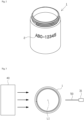
- Fig. 2 is a diagram illustrating a transparent body 1 as an inspection object.
- the transparent body 1 is made of colorless transparent glass, resin or the like and is in a cylindrical shape.
- the transparent body 1 may, however, be translucent.
- the transparent body 1 has a printed portion 2 that is formed on a surface thereof and that displays information such as a product number (for example, "ABC-12345").
- the contents of the information displayed by the printed portion 2 are not specifically limited. According to this embodiment, a location where at least the printed portion 2 is formed, in the transparent body 1 has a cylindrical shape.
- Fig. 1 is a schematic configuration diagram illustrating an inspection device 10.
- the inspection device 10 includes a rotation mechanism 20, a distance adjustment mechanism 30, an illumination device 40, an imaging unit 50 and a control device 60.
- the rotation mechanism 20 configures the “rotation unit”
- the “distance adjustment mechanism 30 configures the "distance adjustment unit”.
- the rotation mechanism 20 is a mechanism configured to rotate the transparent body 1 that is the inspection object.
- the rotation mechanism 20 includes a rotating table 21 and a motor 22.
- the rotating table 21 is a table which the transparent body 1 as the inspection object is placed on, and is configured to be rotatable about a predetermined rotation axis L1. According to the embodiment, at the time of an inspection, the transparent body 1 is placed on the rotating table 21 in such a state that a center axis of the transparent body 1 is aligned with the rotation axis L1.
- a holder unit (not shown) may be provided to control the relative rotation and the relative motion of the transparent body 1 placed on the rotating table 21 relative to the rotating table.
- the motor 22 is a driving device configured to rotate the rotating table 21. Rotating the rotating table 21 by the motor 22 causes the transparent body 1 placed on the rotating table 21 to rotate about the rotation axis L1.
- the distance adjustment mechanism 30 is a mechanism configured to adjust the distance between the transparent body 1 as the inspection object and a light incident surface 51a of a fiber optical plate (hereinafter abbreviated as "FOP") 51 described later in the imaging unit 50.
- the distance adjustment mechanism 30 includes a holding base 31 and a rail 32.
- the holding base 31 is configured to hold the imaging unit 50 at a position on a lateral side of the transparent body 1 as the inspection object and is placed on the rail 32 in such a state as to be slidably movable along a longitudinal direction of the rail 32.
- the rail 32 is extended in a direction perpendicular to the rotation axis L1.
- the distance between the transparent body 1 placed on the rotating table 21 and the light incident surface 51a of the FOP 51 is adjustable by sliding and moving the holding base 31 along the longitudinal direction of the rail 32 to adjust the distance between the rotating table 21 and the imaging unit 50.
- the distance adjustment mechanism 30 is provided with a regulating unit (not shown) configured to allow for or prohibit the sliding and moving of the holding base 31. This regulating unit enables the holding base 31 and thereby the imaging unit 50 to be kept in a stopped state.
- the illumination device 40 is a device configured to irradiate the transparent body 1 as the inspection object with predetermined light and is placed at such a position that the transparent body 1 is placed between the imaging unit 50 and the illumination device 40 in planar view (as shown in Fig. 1 and Fig. 3 : the holding base 31 and others are omitted from the illustration of Fig. 3 ).
- the illumination device 40 includes a surface emitting light source and irradiates the transparent body 1 with diffused light. This configuration causes the diffused light transmitted through the transparent body 1 to reach the imaging unit 50.
- the imaging unit 50 serves to obtain an image that is used for inspection of the transparent body 1.
- the imaging unit 50 includes the FOP 51, a line sensor camera 52, and an oblique ray attenuation body 53.
- the line sensor camera 52 configures the "imaging unit”
- the oblique ray attenuation body 53 configures the "oblique ray attenuation unit”.
- the FOP 51 includes a plurality of optical fibers 511 and a glass body 512 placed around the respective optical fibers 511.
- Each of the optical fibers 511 includes a core 5111 that is made of core glass and that is configured to transmit light rays, and a plurality of clads 5112 that are configured to cover an outer peripheral part of the core 5111.
- the clads 5112 are made of clad glass that has a lower refractive index than that of the core glass, so that the light rays entering the core 5111 are totally reflexed from a boundary surface between the core 5111 and the clads 5112. This configuration enables the light rays to be propagated from one end to the other end of the core 5111.
- the respective optical fibers 511 are linearly extended to be arranged parallel to one another and to be arrayed in parallel along the rotation axis L1.
- the FOP 51 according to the embodiment has a thin plate-like shape (a sheet-like shape). According to the embodiment, the respective optical fibers 511 are arranged adjacent to one another. The respective optical fibers 511 may, however, be arranged to be slightly separate from one another.
- the FOP 51 has the light incident surface 51a that faces the transparent body 1 as the inspection object, a light emission surface 51b that is located on the other side (on an opposite side) to the light incident surface 51a, and a flat plane-like side face 51c that is located between the light incident surface 51a and the light emission surface 51b.
- the respective optical fibers 511 are linearly extended in the direction perpendicular to the rotation axis L1 from the light incident surface 51a toward the light emission surface 51b.
- the FOP 51 enables the light rays passing through inside of the respective optical fibers 511 (the cores 5111) and entering the light incident surface 51a to be transmitted to the light emission surface 51b.
- the light incident surface 51a and the light emission surface 51b are parallel to each other and form flat surfaces orthogonal to the side face 51c. This configuration causes the light rays entering the light incident surface 51a to be emitted from the light emission surface 51b at an emission angle that is equal to an incident angle. For example, the light rays entering the light incident surface 51a at incident angles ⁇ 1 and ⁇ 2 are emitted from the light emission surface 51b at emission angles ⁇ 1 and ⁇ 2.
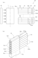
- the light emission surface 51b is provided with a plurality of outlets 511b of the optical fibers 511 for the light rays (the number of the outlets 511b is identical with the number of the optical fibers 511) (as shown in Fig. 4 and Fig. 5 ).
- the oblique ray attenuation body 53 serves to attenuate oblique rays that are inclined with respect to an extending direction of attenuation function elements 531 described below, out of the light rays emitted from the light emission surface 51b.
- the oblique ray attenuation body 53 is located between the light emission surface 51b of the FOP 51 and the line sensor camera 52 and is placed such that one end side of the oblique ray attenuation body 53 is adjacent to the light emission surface 51b and the other end side thereof is adjacent to the line sensor camera 52.
- the oblique ray attenuation body 53 includes a plurality of attenuation function elements 531, each of which is provided corresponding to each optical path between one outlet 511b and one sensor element 52a corresponding to the outlet 511b.
- Each of the attenuation function elements 531 is in a straight cylindrical shape having a side wall 531a formed to surround each optical path between one outlet 511a and one sensor element 52a corresponding to the outlet 511b.
- An inner surface (a surface on an optical path-side) of the side wall 531a is a black rough surface.
- the inner surface of the side wall 531a is configured to absorb the oblique rays. This configuration attenuates the oblique rays out of the light rays emitted from each one outlet 511b and, as a result, causes only the light rays perpendicular to the light incident surface 51a and the light emission surface 51b to readily reach each sensor element 52a.
- the control device 60 controls the motor 22, the illumination device 40 and the like described above and performs a variety of arithmetic operations, based on the image (image data) taken by the line sensor camera 52.
- the control device 60 includes a camera controller 61, an image data storage unit 62, and an image processor 63. According to the embodiment, the image processor 63 configures the "determination unit".
- the camera controller 61 serves to control the imaging timing of the transparent body 1 by the line sensor camera 52. This timing is controlled, in response to a signal from a non-illustrated encoder provided in the rotating table 21, the motor 22 or the like. Imaging by the line sensor camera 52 is performed every time the transparent body 1 is rotated by a predetermined angle.
- the image processor 63 performs a predetermined arithmetic operation and a determination process, based on the images (image data) that are obtained by the line sensor camera 52 and that are stored in the image data storage unit 62, so as to perform good/ poor quality judgment with regard to the conditions of the transparent body 1 and the printing conditions of the printed portion 2. For example, the image processor 63 performs a binarization process of the images (image data) to obtain a binarized image, calculates the area and the length of a "black (0)" section in the binarized image, and compares the calculated area and the calculated length with predetermined reference values, so as to perform the good/ poor quality judgment with regard to the conditions of the transparent body 1 and the printing conditions of the printed portion 2.
- the image processor 63 compares the obtained image with a previously-acquired image including a normal printed portion 2 and performs the good/ poor quality judgment with regard to the printed portion 2, according to the matching degree of these images.
- the method of the good/ poor quality judgment is appropriately modifiable.
- the following describes an inspection procedure of the transparent body 1 using the inspection device 10 configured as described above.
- the transparent body 1 as the inspection object is placed on the rotating table 21.
- the rotation axis L1 of the rotating table 21 is to be adjusted to (to be aligned with) the center axis of the transparent body 1.
- the distance between the imaging unit 50 (more specifically, the light incident surface 51a of the FOP 51) and the transparent body 1 is adjusted by the distance adjustment mechanism 30, such as to cause a side wall portion of the transparent body 1 to be located in an in-focus range R of the imaging unit 50 (the line sensor camera 52) (as shown in Fig. 1 ).
- the presence of the oblique ray attenuation body 53 provides a relatively large area of the range R (i.e., depth of field). This enables a focused image to be obtained without making the transparent body 1 excessively close to the imaging unit 50 (the FOP 51) or without bringing the transparent body 1 into contact with the imaging unit 50 (the FOP 51).
- the illumination device 40 is subsequently turned on by the control device 60. This irradiates the transparent body 1 with the diffused light from the illumination device 40 and causes the light rays transmitted through the transparent body 1 to enter the light incident surface 51a of the FOP 51.
- the light rays entering the light incident surface 51a pass through the respective optical fibers 511 and the respective attenuation function elements 531 and are transmitted toward the line sensor camera 52-side. While the light rays pass through the attenuation function elements 531, the oblique rays out of the light rays entering the light incident surface 51a are attenuated.
- the motor 22 is operated by the control device 60 during an interval of imaging operations by means of the line sensor camera 52, so that the transparent body 1 is rotated by each predetermined angle by means of the rotation mechanism 20.
- An image (image data) with regard to the whole circumference of the side wall portion of the transparent body 1 including the printed portion 2 is obtained by subsequently performing imaging of the transparent body 1 repeatedly by means of the line sensor camera 52 every time the transparent body 1 is rotated.
- the image (image data) obtained by such imaging is sent to the control device 60 and is stored into the image data storage unit 62.
- the image processor 63 performs the good/ poor quality judgment with regard to the conditions of the transparent body 1 (for example, the presence or the absence of any flaw or cracking) and the printing conditions of the printed portion 2 (for example, the presence or the absence of any missing, blurring, bleeding, and the like and the printing positions), based on the image obtained by the line sensor camera 52.
- the transparent body 1 is determined as non-defective.
- the transparent body 1 is determined as defective.
- the good/ poor quality judgment may be performed based on an obtained image, at the stage when an image with regard to part of the side wall portion of the transparent body 1 is obtained by the line sensor camera 52. This means that the good/ poor quality judgment may be performed based on an obtained image, after an image with regard to the whole circumference of the side wall portion of the transparent body 1 is obtained or every time an image with regard to part of the side wall portion of the transparent body 1 is obtained.
- the attenuation function elements 531 of the oblique ray attenuation body 53 serve to attenuate the oblique rays that are inclined with respect to the extending direction of the attenuation function elements 531, out of the light rays emitted from the light emission surface 51b of the FOP 51.
- This configuration enables only the light rays entering from a specific direction to readily reach the sensor elements 52a, even in a state that a clearance is made between the transparent body 1 as the inspection object and the FOP 51, such as to allow the light rays from the transparent body 1-side to readily enter from a variety of directions to the light incident surface of the FOP 51.
- This configuration thus enables a focused image to be obtained more reliably even in the case of imaging the transparent body 1 in the state that a clearance is made between the transparent body 1 and the FOP 51. There is accordingly no need to separate the transparent body 1 and the FOP 51 from each other and make the transparent body 1 and the FOP 51 close to each other again, in the process of rotating and imaging the transparent body 1.
- the configuration thus allows for rotation and imaging of the transparent body 1 in the state that the transparent body 1 and the FOP 51 are kept separate from each other. This increases the speed of the inspection with assuring the high accuracy of the inspection.
- the configuration of the embodiment enables a clearance to be made between the transparent body 1 as the inspection object and the FOP 51, so that there is no need that the surface of the FOP 51 (the light incident surface 51a) located on the transparent body 1-side has a shape that roughly matches with the shape of the side wall portion of the transparent body 1. There is accordingly no need to provide a plurality of different FOPs 51 for respective different transparent bodies 1 as the inspection objects or to replace the FOP 51 with a change of the inspection object. This reduces the cost required for the inspection.
- the light incident surface 51a and the light emission surface 51b are respectively the flat surfaces that are respectively orthogonal to the side face 51c, so that the emission angles of the light rays emitted from the light emission surface 51b can be made identical with the incident angles of the light rays entering the light incident surface 51a.
- This configuration enables the light rays that are transmitted through a location of the transparent body 1 located in front of the light incident surface 51, that orthogonally enter the light incident surface 51, and that are emitted from the light emission surface 51b in a direction perpendicular to the light emission surface 51b, to readily reach the sensor elements 52a.
- This configuration makes it difficult for the light rays obliquely entering the light incident surface 51a (i.e., the oblique rays) to reach the sensor elements 52a. This enables an image of the transparent body 1 suitable for the inspection to be obtained more reliably and further enhances the inspection accuracy.
- the distance adjustment mechanism 30 facilitates handling of a variety of transparent bodies 1 having different shapes and enhances the convenience of the inspection.
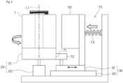
- a distance keeping mechanism 70 serving as the "distance keeping unit” may be provided to keep constant a distance between at least a location of the transparent body 1 as an imaging object of the line sensor camera 52 and the imaging unit 50 (more specifically, the light incident surface 51a of the FOP 51) by moving the imaging unit 50 (the FOP 51) accompanied with rotation of the transparent body 1 by means of the rotation mechanism 20.
- the distance keeping mechanism 70 includes an identical shape component 71 that is provided on a side face of the rotating table 21; a rotatable rotary roller 72 that is fixed to the imaging unit 50 directly or indirectly (in this illustrated example, fixed to the holding base 31 configured to hold the imaging unit 50); a biasing component 73 (for example, a spring or a magnet) configured to apply a biasing force toward the identical shape component 71 to the rotary roller 72; and the distance adjustment mechanism 30.
- a biasing component 73 for example, a spring or a magnet
- the identical shape component 71 has a cross section orthogonal to the rotation axis L1 that is in a substantially identical shape with the shape of an outer circumferential surface (contour line) in a cross section of the transparent body 1 orthogonal to the center axis of the transparent body 1.
- An outer circumferential surface of the rotary roller 72 is in pressure contact with the identical shape component 71 by the biasing force applied from the biasing component 73.
- this distance keeping mechanism 70 causes the imaging unit 50 to be moved with rotation of the transparent body 1, such as to keep constant the distance between the imaging object of the transparent body 1 and the imaging unit 50 (more specifically, the light incident surface 51a of the FOP 51) even when the transparent body 1 has a cross section in a non-circular shape as shown in Fig. 9 and Fig. 10 . Accordingly, this configuration enables a focused image to be obtained more reliably even when the transparent body 1 as the inspection object has a variety of different shapes. This assures the more appropriate inspection (with the higher inspection accuracy) for the transparent bodies 1 having a variety of different shapes.
- the distance keeping mechanism 70 is especially effective when an outer circumferential surface (contour line) of at least a location as an imaging object of the transparent body 1 has a cross section in a non-circular shape (for example, a cross section in an elliptical shape, a cross section in a polygonal shape, or a cross section in a rectangular shape).
- the distance keeping mechanism may be provided with a distance measuring sensor (for example, an ultrasonic sensor) configured to measure a distance from the imaging unit 50 to the side wall portion of the transparent body 1 and a moving mechanism configured to automatically move the imaging unit 50 such that a distance between the FOP 51 and at least a location of the transparent body 1 as the imaging object by the line sensor camera 52 is kept constant, based on the distance measured by the distance measuring sensor.
- a distance measuring sensor for example, an ultrasonic sensor
- a moving mechanism configured to automatically move the imaging unit 50 such that a distance between the FOP 51 and at least a location of the transparent body 1 as the imaging object by the line sensor camera 52 is kept constant, based on the distance measured by the distance measuring sensor.
- An attenuation regulator serving as the "attenuation regulating unit” may be provided to regulate the degree of attenuation of the oblique rays by the attenuation function elements 531.
- the attenuation regulator may be implemented by a function of making the attenuation function element extensible along a direction of an axis thereof (longitudinal direction).
- an attenuation function element 534 may be configured to have a telescopic cylindrical structure including a plurality of cylindrical portions 534a and 534b of different diameters.
- An attenuation regulator 80 may be implemented by a function of making the attenuation function element 534 extensible along a direction of an axis thereof (longitudinal direction) by this telescopic cylindrical structure.
- an attenuation function element 535 may be configured to have a bellows-like structure.
- An attenuation regulator 90 may be implemented by a function of making the attenuation function element 535 extensible along a direction of an axis thereof (longitudinal direction) by this bellows-like structure.
- the attenuation regulator 80 or 90 provided as described above serves to regulate the degree of attenuation of the oblique rays by the attenuation function element 534 or 535.
- the regulation of the degree of attenuation allows for adjustment of the depth of field.
- This configuration accordingly assures the appropriate inspection (with the high inspection accuracy) for the transparent body 1 having a variety of different shapes, for example, the transparent body 1 having a concave-convex surface or the transparent body 1 in a shape other than a cylindrical shape (for example, in an elliptic columnar shape or in a polygonal columnar shape).
- the attenuation function element may be made of an elastic body such as a resin or a rubber, and the attenuation regulator may be implemented by making the attenuation function element extensible in a direction of an axis thereof.
- the illumination device 40 is placed at such a position that the transparent body 1 as the inspection object is placed between the illumination device 40 and the imaging unit 50, and is configured to cause the light transmitted through the transparent body 1 to reach the imaging unit 50.
- the illumination device 40 may be placed on the imaging unit 50-side and may be configured to cause the light reflected from the transparent body 1 to reach the imaging unit 50.
- Stamping may be made on the side wall portion of the transparent body 1 or a label or the like may be applied on the side wall portion.
- the inspection device 10 may be configured to perform the good/ poor quality judgment with regard to the conditions or the position of the stamping or the label.
- the shape of the transparent body 1 as the inspection object is not limited to the shape described in the above embodiment.
- the transparent body 1 having a concave-convex side wall portion may be the inspection object.
- the respective optical fibers 511 are configured to be linearly extended.
- the respective optical fibers 511 may, however, be bent or curved.
- the inspection device 10 may be configured to perform an inspection for the inner surface of the side wall portion, as well as the outer surface of the side wall portion of the transparent body 1.
- the inspection device 10 may be used to perform an inspection for a printed portion formed on the inner surface of the side wall portion.
Landscapes
- Physics & Mathematics (AREA)
- General Physics & Mathematics (AREA)
- Engineering & Computer Science (AREA)
- Life Sciences & Earth Sciences (AREA)
- Immunology (AREA)
- Pathology (AREA)
- Health & Medical Sciences (AREA)
- Chemical & Material Sciences (AREA)
- Analytical Chemistry (AREA)
- Biochemistry (AREA)
- General Health & Medical Sciences (AREA)
- Remote Sensing (AREA)
- Theoretical Computer Science (AREA)
- Computer Vision & Pattern Recognition (AREA)
- Quality & Reliability (AREA)
- Acoustics & Sound (AREA)
- Environmental & Geological Engineering (AREA)
- Geology (AREA)
- General Life Sciences & Earth Sciences (AREA)
- Geophysics (AREA)
- Textile Engineering (AREA)
- Investigating Materials By The Use Of Optical Means Adapted For Particular Applications (AREA)
- Measurement Of Mechanical Vibrations Or Ultrasonic Waves (AREA)
Abstract
Description
- The present disclosure relates to an inspection device configured to perform an inspection for a cylindrical transparent body.
- Containers, lamps and the like having a cylindrical transparent body made of transparent or translucent glass have been known conventionally. For example, a liquid such as a cosmetic product or the like or a component of the lamp may be placed in the transparent body. A printed portion consisting of letters, characters, signs, symbols and the like indicating various pieces of information, such as a product name, a product number, a model number and the like may be formed on a side wall portion of the transparent body.
- A known configuration of an inspection device used to perform an inspection for the transparent body as described above includes a fiber optical plate configured to enable light entering a light incident surface thereof to be transmitted to a light emission surface thereof and to cause an optical image of the transparent body that is an object to be inspected (hereinafter referred to as "inspection object") to be projected on this light emission surface; and an imaging unit configured to perform imaging of an optical image of the inspection object projected on the light emission surface (as described in, for example, Patent Literature 1). This device alternately repeats rotating the inspection object by a predetermined angle and imaging an optical image of the inspection object and performs an inspection, based on an image obtained by such alternate repetition. This device accordingly allows for an inspection for the whole circumference of a side wall portion of the inspection object.
- Patent Literature 1:
Japanese Patent No. 2010-271131A - The device described in
Patent Literature 1 mentioned above performs imaging of an optical image in the state that the light incident surface of the fiber optical plate and the inspection object are made close to each other to be substantially brought into contact with each other, with a view to focusing the optical image. It is thus required to cause the shape of the light incident surface of the fiber optical plate, which is located on the inspection object-side, to substantially match with the shape of the side wall portion of the inspection object. Accordingly, there is a need to provide a plurality of different fiber optical plates for respective different inspection objects. In the case of a change of the inspection object, there is also a need to replace the fiber optical plate corresponding to the inspection object that is changed. This is likely to increase the cost of the inspection. - In order to rotate the inspection object, there is also a need to once separate the inspection object and the fiber optical plate from each other. For an inspection of the whole circumference of the side wall portion of the inspection object, it is accordingly required to repeat a series of processes of separating the inspection object and the fiber optical plate from each other, rotating the inspection object by a predetermined angle, subsequently making the inspection object and the fiber optical plate close to each other again, and performing imaging of an optical image. This makes it difficult to increase the speed of the inspection.
- By taking into account the circumstances described above, an object of the present disclosure is to provide an inspection device configured to reduce the cost of an inspection and to increase the speed of the inspection.
- The following describes each of various aspects provided adequately to solve the problems described above. Functions and advantageous effects that are characteristic of each of the aspects are also described as appropriate.
-
Aspect 1. There is provided an inspection device configured to perform an inspection for a transparent body that is a transparent or translucent cylindrical body as an inspection object. The inspection device comprises an irradiation unit configured to irradiate the inspection object with predetermined light; a rotation unit configured to rotate the inspection object about a predetermined rotation axis; a fiber optical plate provided with a plurality of optical fibers that are arrayed in parallel along a direction of the rotation axis, and configured such as to cause light rays entering a light incident surface of the fiber optical plate, which faces the inspection object, to pass through the optical fibers and to be transmitted to a light emission surface located on an opposite side to the light incident surface, wherein the light emission surface is provided with a plurality of outlets of the optical fibers as outlets for the light rays; an imaging unit provided with a plurality of sensor elements that are aligned, that are configured such that one of the sensor elements corresponds to one of the outlets, and that are configured to take an image of the inspection object when the sensor elements receive the light rays transmitted through the fiber optical plate; a determination unit configured to perform good/ poor quality judgment of the inspection object, based on an image obtained by the imaging unit; and an oblique ray attenuation unit configured by a plurality of attenuation function elements that are arrayed in parallel and that are in a straight cylindrical shape to surround an optical path between each of the outlets and each of the sensor elements corresponding to the outlet, and located between the light emission surface and the imaging unit, wherein the attenuation function elements have a function of attenuating oblique rays that are inclined with respect to an extending direction of the attenuation function elements, out of light rays emitted from the light emission surface. - In the configuration of the
aspect 1 described above, the attenuation function elements of the oblique ray attenuation unit serve to attenuate the oblique rays that are inclined with respect to the extending direction of the attenuation function elements, out of the light rays emitted from the light emission surface of the fiber optical plate. This configuration enables only the light rays entering from a specific direction to readily reach the sensor elements, even in a state that a clearance is made between the inspection object and the fiber optical plate, such as to allow the light rays from the inspection object-side to readily enter from a variety of directions to the light incident surface of the fiber optical plate. This prevents a reduction in the depth of field caused by the effects of the oblique rays (a reduction in a distance range between the inspection object and the fiber optical plate that enables a focused image to be obtained) and extends the depth of field. This configuration thus enables a focused image to be obtained more reliably even in the case of imaging the inspection object in the state that a clearance is made between the inspection object and the fiber optical plate. There is accordingly no need to separate the inspection object and the fiber optical plate from each other and make the inspection object and the fiber optical plate close to each other again, in the process of rotating and imaging the inspection object. The configuration thus allows for rotation and imaging of the inspection object in the state that the inspection object and the fiber optical plate are kept separate from each other. This increases the speed of the inspection with assuring the high accuracy of the inspection. - Furthermore, this configuration enables a clearance to be made between the inspection object and the fiber optical plate, so that there is no need that the surface of the fiber optical plate (the light incident surface) located on the inspection object-side has a shape that roughly matches with the shape of a side wall portion of the inspection object. There is accordingly no need to provide a plurality of different fiber optical plates for respective different inspection objects or to replace the fiber optical plate with a change of the inspection object. This reduces the cost required for the inspection.
-
Aspect 2. In the inspection device described in theabove aspect 1, the light incident surface and the light emission surface may form flat surfaces that are orthogonal to a side face of the fiber optical plate located between the light incident surface and the light emission surface. - The configuration of the
above aspect 2 enables the emission angles of the light rays emitted from the light emission surface to be identical with the incident angles of the light rays entering the light incident surface. This configuration enables the light rays that are transmitted through or reflected from a location of the inspection object located in front of the light incident surface, that orthogonally enter the light incident surface, and that are emitted from the light emission surface in a direction perpendicular to the light emission surface, to readily reach the sensor elements. This configuration, on the other hand, makes it difficult for the light rays obliquely entering the light incident surface (i.e., the oblique rays) to reach the sensor elements. This enables an image of the inspection object suitable for the inspection to be obtained more reliably and further enhances the inspection accuracy. - Aspect 3. The inspection device described in either the
above aspect 1 or theabove aspect 2 may further comprise a distance adjustment unit configured to move at least one of the inspection object and the fiber optical plate, so as to adjust a distance between the inspection object and the light incident surface of the fiber optical plate. - The configuration of the above aspect 3 facilitates handling of a variety of inspection objects having different shapes and enhances the convenience of the inspection.
- Aspect 4. The inspection device described in any one of the
above aspects 1 to 3 may further comprise an attenuation regulating unit configured to regulate a degree of attenuation of the oblique rays by the attenuation function elements. - In the configuration of the above aspect 4, the attenuation regulating unit serves to regulate the degree of attenuation of the oblique rays by the attenuation function elements. The regulation of the degree of attenuation allows for adjustment of the depth of field. This configuration accordingly assures the appropriate inspection (with the high inspection accuracy) for inspection objects having a variety of different shapes, for example, an inspection object having a concave-convex surface or an inspection object in a shape other than a cylindrical shape (for example, in an elliptic columnar shape or in a polygonal columnar shape).
- Aspect 5. In the inspection device described in the above aspect 4, the attenuation regulating unit may be implemented by a function of making the attenuation function element extensible along a direction of an axis thereof.
- The configuration of the above aspect 5 enables the degree of attenuation of the oblique rays to be regulated by extension and contraction of the attenuation function element. This accordingly enables the attenuation regulating unit to be implemented by a relatively simple configuration and reduces an increase in the cost relating to manufacture of the device and the like.
- Aspect 6. The inspection device described in any one of the
above aspects 1 to 5 may further comprise a distance keeping unit configured to keep constant a distance between a location of the inspection object that is an imaging object by the imaging unit and the light incident surface of the fiber optical plate by moving at least one of the inspection object and the fiber optical plate with rotation of the inspection object by means of the rotation unit. - The configuration of the above aspect 6 enables the distance between the inspection object (more specifically, a location thereof as an imaging object) and the light incident surface of the fiber optical plate to be kept constant, while rotating the inspection object. Accordingly, this configuration enables a focused image to be obtained more reliably even when the inspection object has a variety of different shapes. This assures the more appropriate inspection (with the higher inspection accuracy) for the inspection objects having a variety of different shapes.
-
-
Fig. 1 is a schematic configuration diagram illustrating an inspection device; -
Fig. 2 is a schematic perspective view illustrating a transparent body as an inspection object; -
Fig. 3 is a schematic plan view illustrating the inspection device; -
Fig. 4 is a schematic view illustrating an imaging unit and others; -
Fig. 5 is a schematic perspective view illustrating the configuration of a fiber optical plate and others; -
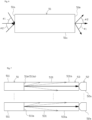
Fig. 6 is a schematic view illustrating a light incident surface, a light emission surface and a side face of the fiber optical plate; -
Fig. 7 is a schematic view illustrating an oblique ray attenuation body; -
Fig. 8 is a schematic view illustrating a distance keeping mechanism according to another embodiment; -
Fig. 9 is a schematic perspective view illustrating the move of the imaging unit in conjunction with the rotation of the transparent body according to another embodiment; -
Fig. 10 is a schematic perspective view illustrating the move of the imaging unit in conjunction with the rotation of the transparent body according to another embodiment; -
Fig. 11 is a schematic perspective view illustrating an attenuation function element having a telescopic cylindrical structure according to another embodiment; and -
Fig. 12 is a schematic perspective view illustrating an attenuation function element having a bellows-like structure according to another embodiment. - The following describes one embodiment with reference to drawings.
Fig. 2 is a diagram illustrating atransparent body 1 as an inspection object. - The
transparent body 1 is made of colorless transparent glass, resin or the like and is in a cylindrical shape. Thetransparent body 1 may, however, be translucent. Thetransparent body 1 has a printedportion 2 that is formed on a surface thereof and that displays information such as a product number (for example, "ABC-12345"). The contents of the information displayed by the printedportion 2 are not specifically limited. According to this embodiment, a location where at least the printedportion 2 is formed, in thetransparent body 1 has a cylindrical shape. - The following describes an inspection device configured to perform an inspection for the
transparent body 1 described above.Fig. 1 is a schematic configuration diagram illustrating aninspection device 10. - The
inspection device 10 includes arotation mechanism 20, adistance adjustment mechanism 30, anillumination device 40, animaging unit 50 and acontrol device 60. According to the embodiment, therotation mechanism 20 configures the "rotation unit", and the "distance adjustment mechanism 30 configures the "distance adjustment unit". - The
rotation mechanism 20 is a mechanism configured to rotate thetransparent body 1 that is the inspection object. Therotation mechanism 20 includes a rotating table 21 and amotor 22. - The rotating table 21 is a table which the
transparent body 1 as the inspection object is placed on, and is configured to be rotatable about a predetermined rotation axis L1. According to the embodiment, at the time of an inspection, thetransparent body 1 is placed on the rotating table 21 in such a state that a center axis of thetransparent body 1 is aligned with the rotation axis L1. A holder unit (not shown) may be provided to control the relative rotation and the relative motion of thetransparent body 1 placed on the rotating table 21 relative to the rotating table. - The
motor 22 is a driving device configured to rotate the rotating table 21. Rotating the rotating table 21 by themotor 22 causes thetransparent body 1 placed on the rotating table 21 to rotate about the rotation axis L1. - The
distance adjustment mechanism 30 is a mechanism configured to adjust the distance between thetransparent body 1 as the inspection object and alight incident surface 51a of a fiber optical plate (hereinafter abbreviated as "FOP") 51 described later in theimaging unit 50. Thedistance adjustment mechanism 30 includes a holdingbase 31 and arail 32. - The holding
base 31 is configured to hold theimaging unit 50 at a position on a lateral side of thetransparent body 1 as the inspection object and is placed on therail 32 in such a state as to be slidably movable along a longitudinal direction of therail 32. Therail 32 is extended in a direction perpendicular to the rotation axis L1. The distance between thetransparent body 1 placed on the rotating table 21 and thelight incident surface 51a of theFOP 51 is adjustable by sliding and moving the holdingbase 31 along the longitudinal direction of therail 32 to adjust the distance between the rotating table 21 and theimaging unit 50. Thedistance adjustment mechanism 30 is provided with a regulating unit (not shown) configured to allow for or prohibit the sliding and moving of the holdingbase 31. This regulating unit enables the holdingbase 31 and thereby theimaging unit 50 to be kept in a stopped state. - The
illumination device 40 is a device configured to irradiate thetransparent body 1 as the inspection object with predetermined light and is placed at such a position that thetransparent body 1 is placed between theimaging unit 50 and theillumination device 40 in planar view (as shown inFig. 1 andFig. 3 : the holdingbase 31 and others are omitted from the illustration ofFig. 3 ). According to the embodiment, theillumination device 40 includes a surface emitting light source and irradiates thetransparent body 1 with diffused light. This configuration causes the diffused light transmitted through thetransparent body 1 to reach theimaging unit 50. - The
imaging unit 50 serves to obtain an image that is used for inspection of thetransparent body 1. As shown inFig. 4 , theimaging unit 50 includes theFOP 51, aline sensor camera 52, and an obliqueray attenuation body 53. According to the embodiment, theline sensor camera 52 configures the "imaging unit", and the obliqueray attenuation body 53 configures the "oblique ray attenuation unit". - As shown in
Fig. 4 and Fig. 5 , theFOP 51 includes a plurality ofoptical fibers 511 and aglass body 512 placed around the respectiveoptical fibers 511. Each of theoptical fibers 511 includes acore 5111 that is made of core glass and that is configured to transmit light rays, and a plurality ofclads 5112 that are configured to cover an outer peripheral part of thecore 5111. Theclads 5112 are made of clad glass that has a lower refractive index than that of the core glass, so that the light rays entering thecore 5111 are totally reflexed from a boundary surface between the core 5111 and theclads 5112. This configuration enables the light rays to be propagated from one end to the other end of thecore 5111. - The respective
optical fibers 511 are linearly extended to be arranged parallel to one another and to be arrayed in parallel along the rotation axis L1. TheFOP 51 according to the embodiment has a thin plate-like shape (a sheet-like shape). According to the embodiment, the respectiveoptical fibers 511 are arranged adjacent to one another. The respectiveoptical fibers 511 may, however, be arranged to be slightly separate from one another. - As shown in
Figs. 4 to 6 , theFOP 51 has thelight incident surface 51a that faces thetransparent body 1 as the inspection object, alight emission surface 51b that is located on the other side (on an opposite side) to thelight incident surface 51a, and a flat plane-like side face 51c that is located between thelight incident surface 51a and thelight emission surface 51b. The respectiveoptical fibers 511 are linearly extended in the direction perpendicular to the rotation axis L1 from thelight incident surface 51a toward thelight emission surface 51b. TheFOP 51 enables the light rays passing through inside of the respective optical fibers 511 (the cores 5111) and entering thelight incident surface 51a to be transmitted to thelight emission surface 51b. - The
light incident surface 51a and thelight emission surface 51b are parallel to each other and form flat surfaces orthogonal to theside face 51c. This configuration causes the light rays entering thelight incident surface 51a to be emitted from thelight emission surface 51b at an emission angle that is equal to an incident angle. For example, the light rays entering thelight incident surface 51a at incident angles θ1 and θ2 are emitted from thelight emission surface 51b at emission angles θ1 and θ2. - Furthermore, the
light emission surface 51b is provided with a plurality ofoutlets 511b of theoptical fibers 511 for the light rays (the number of theoutlets 511b is identical with the number of the optical fibers 511) (as shown inFig. 4 and Fig. 5 ). - The
line sensor camera 52 serves to take an image of thetransparent body 1 as the inspection object. Theline sensor camera 52 includes a plurality ofsensor elements 52a (for example, photodiodes or the like) that are configured to receive the light rays transmitted through theFOP 51. Therespective sensor elements 52a are aligned along the direction of the rotation axis L1 and are configured such that onesensor element 52a corresponds to oneoutlet 511b. Accordingly, each of thesensor elements 52a is allowed to receive the light rays passing through corresponding one optical fiber 511 (corresponding one core 5111). Therespective sensor elements 52a receive the light rays transmitted through theFOP 51. This achieves imaging of thetransparent body 1 as the inspection object. The image (image data) obtained by imaging is output to thecontrol device 60. - The oblique
ray attenuation body 53 serves to attenuate oblique rays that are inclined with respect to an extending direction ofattenuation function elements 531 described below, out of the light rays emitted from thelight emission surface 51b. The obliqueray attenuation body 53 is located between thelight emission surface 51b of theFOP 51 and theline sensor camera 52 and is placed such that one end side of the obliqueray attenuation body 53 is adjacent to thelight emission surface 51b and the other end side thereof is adjacent to theline sensor camera 52. As shown inFig. 5 andFig. 7 , the obliqueray attenuation body 53 includes a plurality ofattenuation function elements 531, each of which is provided corresponding to each optical path between oneoutlet 511b and onesensor element 52a corresponding to theoutlet 511b. - Each of the
attenuation function elements 531 is in a straight cylindrical shape having aside wall 531a formed to surround each optical path between one outlet 511a and onesensor element 52a corresponding to theoutlet 511b. An inner surface (a surface on an optical path-side) of theside wall 531a is a black rough surface. The inner surface of theside wall 531a is configured to absorb the oblique rays. This configuration attenuates the oblique rays out of the light rays emitted from each oneoutlet 511b and, as a result, causes only the light rays perpendicular to thelight incident surface 51a and thelight emission surface 51b to readily reach eachsensor element 52a. - Referring back to
Fig. 1 , thecontrol device 60 controls themotor 22, theillumination device 40 and the like described above and performs a variety of arithmetic operations, based on the image (image data) taken by theline sensor camera 52. Thecontrol device 60 includes acamera controller 61, an imagedata storage unit 62, and animage processor 63. According to the embodiment, theimage processor 63 configures the "determination unit". - The
camera controller 61 serves to control the imaging timing of thetransparent body 1 by theline sensor camera 52. This timing is controlled, in response to a signal from a non-illustrated encoder provided in the rotating table 21, themotor 22 or the like. Imaging by theline sensor camera 52 is performed every time thetransparent body 1 is rotated by a predetermined angle. - The image
data storage unit 62 serves to sequentially store image data taken by theline sensor camera 52 in time series. This obtains an image (image data) of thetransparent body 1 including at least the entirety of the printedportion 2. - The
image processor 63 performs a predetermined arithmetic operation and a determination process, based on the images (image data) that are obtained by theline sensor camera 52 and that are stored in the imagedata storage unit 62, so as to perform good/ poor quality judgment with regard to the conditions of thetransparent body 1 and the printing conditions of the printedportion 2. For example, theimage processor 63 performs a binarization process of the images (image data) to obtain a binarized image, calculates the area and the length of a "black (0)" section in the binarized image, and compares the calculated area and the calculated length with predetermined reference values, so as to perform the good/ poor quality judgment with regard to the conditions of thetransparent body 1 and the printing conditions of the printedportion 2. In another example, theimage processor 63 compares the obtained image with a previously-acquired image including a normal printedportion 2 and performs the good/ poor quality judgment with regard to the printedportion 2, according to the matching degree of these images. The method of the good/ poor quality judgment is appropriately modifiable. - The following describes an inspection procedure of the
transparent body 1 using theinspection device 10 configured as described above. - In the process of inspection, first of all, the
transparent body 1 as the inspection object is placed on the rotating table 21. At this moment, the rotation axis L1 of the rotating table 21 is to be adjusted to (to be aligned with) the center axis of thetransparent body 1. The distance between the imaging unit 50 (more specifically, thelight incident surface 51a of the FOP 51) and thetransparent body 1 is adjusted by thedistance adjustment mechanism 30, such as to cause a side wall portion of thetransparent body 1 to be located in an in-focus range R of the imaging unit 50 (the line sensor camera 52) (as shown inFig. 1 ). There may, however, be a sufficiently large clearance between thelight incident surface 51a of the imaging unit 50 (the FOP 51) and the side wall portion of thetransparent body 1. This is because the presence of the obliqueray attenuation body 53 provides a relatively large area of the range R (i.e., depth of field). This enables a focused image to be obtained without making thetransparent body 1 excessively close to the imaging unit 50 (the FOP 51) or without bringing thetransparent body 1 into contact with the imaging unit 50 (the FOP 51). - The
illumination device 40 is subsequently turned on by thecontrol device 60. This irradiates thetransparent body 1 with the diffused light from theillumination device 40 and causes the light rays transmitted through thetransparent body 1 to enter thelight incident surface 51a of theFOP 51. The light rays entering thelight incident surface 51a pass through the respectiveoptical fibers 511 and the respectiveattenuation function elements 531 and are transmitted toward the line sensor camera 52-side. While the light rays pass through theattenuation function elements 531, the oblique rays out of the light rays entering thelight incident surface 51a are attenuated. - The
motor 22 is operated by thecontrol device 60 during an interval of imaging operations by means of theline sensor camera 52, so that thetransparent body 1 is rotated by each predetermined angle by means of therotation mechanism 20. An image (image data) with regard to the whole circumference of the side wall portion of thetransparent body 1 including the printedportion 2 is obtained by subsequently performing imaging of thetransparent body 1 repeatedly by means of theline sensor camera 52 every time thetransparent body 1 is rotated. The image (image data) obtained by such imaging is sent to thecontrol device 60 and is stored into the imagedata storage unit 62. - Furthermore, the
image processor 63 performs the good/ poor quality judgment with regard to the conditions of the transparent body 1 (for example, the presence or the absence of any flaw or cracking) and the printing conditions of the printed portion 2 (for example, the presence or the absence of any missing, blurring, bleeding, and the like and the printing positions), based on the image obtained by theline sensor camera 52. When there is no defect in the whole circumference of the side wall portion of thetransparent body 1 including the printedportion 2, thetransparent body 1 is determined as non-defective. When there is any defect in at least part of the side wall portion of thetransparent body 1, on the other hand, thetransparent body 1 is determined as defective. - The good/ poor quality judgment may be performed based on an obtained image, at the stage when an image with regard to part of the side wall portion of the
transparent body 1 is obtained by theline sensor camera 52. This means that the good/ poor quality judgment may be performed based on an obtained image, after an image with regard to the whole circumference of the side wall portion of thetransparent body 1 is obtained or every time an image with regard to part of the side wall portion of thetransparent body 1 is obtained. - As described above in detail, according to the embodiment, the
attenuation function elements 531 of the obliqueray attenuation body 53 serve to attenuate the oblique rays that are inclined with respect to the extending direction of theattenuation function elements 531, out of the light rays emitted from thelight emission surface 51b of theFOP 51. This configuration enables only the light rays entering from a specific direction to readily reach thesensor elements 52a, even in a state that a clearance is made between thetransparent body 1 as the inspection object and theFOP 51, such as to allow the light rays from the transparent body 1-side to readily enter from a variety of directions to the light incident surface of theFOP 51. This prevents a reduction in the depth of field caused by the effects of the oblique rays and extends the depth of field. This configuration thus enables a focused image to be obtained more reliably even in the case of imaging thetransparent body 1 in the state that a clearance is made between thetransparent body 1 and theFOP 51. There is accordingly no need to separate thetransparent body 1 and theFOP 51 from each other and make thetransparent body 1 and theFOP 51 close to each other again, in the process of rotating and imaging thetransparent body 1. The configuration thus allows for rotation and imaging of thetransparent body 1 in the state that thetransparent body 1 and theFOP 51 are kept separate from each other. This increases the speed of the inspection with assuring the high accuracy of the inspection. - Furthermore, the configuration of the embodiment enables a clearance to be made between the
transparent body 1 as the inspection object and theFOP 51, so that there is no need that the surface of the FOP 51 (thelight incident surface 51a) located on the transparent body 1-side has a shape that roughly matches with the shape of the side wall portion of thetransparent body 1. There is accordingly no need to provide a plurality ofdifferent FOPs 51 for respective differenttransparent bodies 1 as the inspection objects or to replace theFOP 51 with a change of the inspection object. This reduces the cost required for the inspection. - Additionally, the
light incident surface 51a and thelight emission surface 51b are respectively the flat surfaces that are respectively orthogonal to theside face 51c, so that the emission angles of the light rays emitted from thelight emission surface 51b can be made identical with the incident angles of the light rays entering thelight incident surface 51a. This configuration enables the light rays that are transmitted through a location of thetransparent body 1 located in front of thelight incident surface 51, that orthogonally enter thelight incident surface 51, and that are emitted from thelight emission surface 51b in a direction perpendicular to thelight emission surface 51b, to readily reach thesensor elements 52a. This configuration, on the other hand, makes it difficult for the light rays obliquely entering thelight incident surface 51a (i.e., the oblique rays) to reach thesensor elements 52a. This enables an image of thetransparent body 1 suitable for the inspection to be obtained more reliably and further enhances the inspection accuracy. - Moreover, the
distance adjustment mechanism 30 facilitates handling of a variety oftransparent bodies 1 having different shapes and enhances the convenience of the inspection. - The present disclosure is not limited to the description of the above embodiment but may be implemented, for example, by configurations described below. The present disclosure may also be naturally implemented by applications and modifications other than those illustrated below.
- (a) As shown in
Fig. 8 , adistance keeping mechanism 70 serving as the "distance keeping unit" may be provided to keep constant a distance between at least a location of thetransparent body 1 as an imaging object of theline sensor camera 52 and the imaging unit 50 (more specifically, thelight incident surface 51a of the FOP 51) by moving the imaging unit 50 (the FOP 51) accompanied with rotation of thetransparent body 1 by means of therotation mechanism 20. - In the illustrated example of
Fig. 8 , thedistance keeping mechanism 70 includes anidentical shape component 71 that is provided on a side face of the rotating table 21; a rotatablerotary roller 72 that is fixed to theimaging unit 50 directly or indirectly (in this illustrated example, fixed to the holdingbase 31 configured to hold the imaging unit 50); a biasing component 73 (for example, a spring or a magnet) configured to apply a biasing force toward theidentical shape component 71 to therotary roller 72; and thedistance adjustment mechanism 30. Theidentical shape component 71 has a cross section orthogonal to the rotation axis L1 that is in a substantially identical shape with the shape of an outer circumferential surface (contour line) in a cross section of thetransparent body 1 orthogonal to the center axis of thetransparent body 1. An outer circumferential surface of therotary roller 72 is in pressure contact with theidentical shape component 71 by the biasing force applied from the biasingcomponent 73. - Providing this
distance keeping mechanism 70 causes theimaging unit 50 to be moved with rotation of thetransparent body 1, such as to keep constant the distance between the imaging object of thetransparent body 1 and the imaging unit 50 (more specifically, thelight incident surface 51a of the FOP 51) even when thetransparent body 1 has a cross section in a non-circular shape as shown inFig. 9 and Fig. 10 . Accordingly, this configuration enables a focused image to be obtained more reliably even when thetransparent body 1 as the inspection object has a variety of different shapes. This assures the more appropriate inspection (with the higher inspection accuracy) for thetransparent bodies 1 having a variety of different shapes. - The
distance keeping mechanism 70 is especially effective when an outer circumferential surface (contour line) of at least a location as an imaging object of thetransparent body 1 has a cross section in a non-circular shape (for example, a cross section in an elliptical shape, a cross section in a polygonal shape, or a cross section in a rectangular shape). - The distance keeping mechanism may be provided with a distance measuring sensor (for example, an ultrasonic sensor) configured to measure a distance from the
imaging unit 50 to the side wall portion of thetransparent body 1 and a moving mechanism configured to automatically move theimaging unit 50 such that a distance between theFOP 51 and at least a location of thetransparent body 1 as the imaging object by theline sensor camera 52 is kept constant, based on the distance measured by the distance measuring sensor. In this case, there is no need to provide theidentical shape component 71 having the shape adjusted to the shape of thetransparent body 1 as the inspection object. This accordingly suppresses an increase in the cost. - (b) An attenuation regulator serving as the "attenuation regulating unit" may be provided to regulate the degree of attenuation of the oblique rays by the
attenuation function elements 531. The attenuation regulator may be implemented by a function of making the attenuation function element extensible along a direction of an axis thereof (longitudinal direction). For example, as shown inFig. 11 , anattenuation function element 534 may be configured to have a telescopic cylindrical structure including a plurality ofcylindrical portions attenuation regulator 80 may be implemented by a function of making theattenuation function element 534 extensible along a direction of an axis thereof (longitudinal direction) by this telescopic cylindrical structure. In another example, as shown inFig. 12 , anattenuation function element 535 may be configured to have a bellows-like structure. Anattenuation regulator 90 may be implemented by a function of making theattenuation function element 535 extensible along a direction of an axis thereof (longitudinal direction) by this bellows-like structure. - The
attenuation regulator attenuation function element transparent body 1 having a variety of different shapes, for example, thetransparent body 1 having a concave-convex surface or thetransparent body 1 in a shape other than a cylindrical shape (for example, in an elliptic columnar shape or in a polygonal columnar shape). - According to a modification, the attenuation function element may be made of an elastic body such as a resin or a rubber, and the attenuation regulator may be implemented by making the attenuation function element extensible in a direction of an axis thereof.
- (c) According to the embodiment described above, the
illumination device 40 is placed at such a position that thetransparent body 1 as the inspection object is placed between theillumination device 40 and theimaging unit 50, and is configured to cause the light transmitted through thetransparent body 1 to reach theimaging unit 50. According to a modification, theillumination device 40 may be placed on the imaging unit 50-side and may be configured to cause the light reflected from thetransparent body 1 to reach theimaging unit 50. - (d) Stamping may be made on the side wall portion of the
transparent body 1 or a label or the like may be applied on the side wall portion. In this case, theinspection device 10 may be configured to perform the good/ poor quality judgment with regard to the conditions or the position of the stamping or the label. - (e) The shape of the
transparent body 1 as the inspection object is not limited to the shape described in the above embodiment. For example, thetransparent body 1 having a concave-convex side wall portion may be the inspection object. - (f) According to the embodiment described above, the respective
optical fibers 511 are configured to be linearly extended. The respectiveoptical fibers 511 may, however, be bent or curved. - (g) The
inspection device 10 may be configured to perform an inspection for the inner surface of the side wall portion, as well as the outer surface of the side wall portion of thetransparent body 1. For example, theinspection device 10 may be used to perform an inspection for a printed portion formed on the inner surface of the side wall portion. - 1... transparent body (inspection object), 10... inspection device, 20... rotation mechanism (rotation unit), 30... distance adjustment mechanism (distance adjustment unit), 40... illumination device (illumination unit), 51... fiber optical plate, 51a... light incident surface, 51b... light emission surface, 51c... side face, 52... line sensor camera (imaging unit), 53... oblique ray attenuation body (oblique ray attenuation unit), 63... image processor (determination unit), 70... distance keeping mechanism (distance keeping unit), 80, 90... attenuation regulator (attenuation regulating unit), 511... optical fiber, 511b... outlet, 531... attenuation function element, L1... rotation axis
Claims (6)
- An inspection device configured to perform an inspection for a transparent body that is a transparent or translucent cylindrical body as an inspection object, the inspection device comprising:an irradiation unit configured to irradiate the inspection object with predetermined light;a rotation unit configured to rotate the inspection object about a predetermined rotation axis;a fiber optical plate provided with a plurality of optical fibers that are arrayed in parallel along a direction of the rotation axis, and configured such as to cause light rays entering a light incident surface of the fiber optical plate, which faces the inspection object, to pass through the optical fibers and to be transmitted to a light emission surface located on an opposite side to the light incident surface, wherein the light emission surface is provided with a plurality of outlets of the optical fibers as outlets for the light rays;an imaging unit provided with a plurality of sensor elements that are aligned, that are configured such that one of the sensor elements corresponds to one of the outlets, and that are configured to take an image of the inspection object when the sensor elements receive the light rays transmitted through the fiber optical plate;a determination unit configured to perform good/ poor quality judgment of the inspection object, based on an image obtained by the imaging unit; andan oblique ray attenuation unit configured by a plurality of attenuation function elements that are arrayed in parallel and that are in a straight cylindrical shape to surround an optical path between each of the outlets and each of the sensor elements corresponding to the outlet, and located between the light emission surface and the imaging unit, whereinthe attenuation function elements have a function of attenuating oblique rays that are inclined with respect to an extending direction of the attenuation function elements, out of light rays emitted from the light emission surface.
- The inspection device according to claim 1,
wherein the light incident surface and the light emission surface form flat surfaces that are orthogonal to a side face of the fiber optical plate located between the light incident surface and the light emission surface. - The inspection device according to either claim 1 or claim 2, further comprising:
a distance adjustment unit configured to move at least one of the inspection object and the fiber optical plate, so as to adjust a distance between the inspection object and the light incident surface of the fiber optical plate. - The inspection device according to any one of claims 1 to 3, further comprising:
an attenuation regulating unit configured to regulate a degree of attenuation of the oblique rays by the attenuation function elements. - The inspection device according to claim 4,
wherein the attenuation regulating unit is implemented by a function of making the attenuation function element extensible along a direction of an axis thereof. - The inspection device according to any one of claims 1 to 5, further comprising:
a distance keeping unit configured to keep constant a distance between a location of the inspection object that is an imaging object by the imaging unit and the light incident surface of the fiber optical plate by moving at least one of the inspection object and the fiber optical plate with rotation of the inspection object by means of the rotation unit.
Applications Claiming Priority (2)
| Application Number | Priority Date | Filing Date | Title |
|---|---|---|---|
| JP2022003898A JP7217370B1 (en) | 2022-01-13 | 2022-01-13 | inspection equipment |
| PCT/JP2022/033216 WO2023135856A1 (en) | 2022-01-13 | 2022-09-05 | Inspection device |
Publications (2)
| Publication Number | Publication Date |
|---|---|
| EP4465026A1 true EP4465026A1 (en) | 2024-11-20 |
| EP4465026A4 EP4465026A4 (en) | 2025-12-10 |
Family
ID=85129914
Family Applications (1)
| Application Number | Title | Priority Date | Filing Date |
|---|---|---|---|
| EP22920380.7A Pending EP4465026A4 (en) | 2022-01-13 | 2022-09-05 | INSPECTION DEVICE |
Country Status (5)
| Country | Link |
|---|---|
| US (1) | US12680965B2 (en) |
| EP (1) | EP4465026A4 (en) |
| JP (1) | JP7217370B1 (en) |
| CN (2) | CN118369570A (en) |
| WO (1) | WO2023135856A1 (en) |
Family Cites Families (13)
| Publication number | Priority date | Publication date | Assignee | Title |
|---|---|---|---|---|
| US3942897A (en) * | 1972-10-31 | 1976-03-09 | Eisai Co., Ltd. | Method and apparatus for detecting solid substances contained in liquid |
| DE3307575C2 (en) * | 1983-03-03 | 1984-12-20 | Erich Dipl.-Geophys. 8372 Lindberg Lippmann | Electrodynamic seismometer |
| JPS631958A (en) * | 1986-06-23 | 1988-01-06 | Hitachi Ltd | Apparatus for automatically positioning visual sensor |
| JP3098045B2 (en) * | 1990-12-13 | 2000-10-10 | シュルンベルジェ オーバーシーズ エス.エイ. | Electrodynamic accelerometer |
| JP3325935B2 (en) * | 1992-12-01 | 2002-09-17 | 旭化成株式会社 | Plastic fiber optic plate |
| EP1066533B1 (en) * | 1998-03-25 | 2005-05-11 | Thomas R. Vanzandt | Apparatus for improving performance of a force balance accelerometer based on a single-coil velocity geophone |
| JP2000138792A (en) | 1998-10-30 | 2000-05-16 | Sharp Corp | Image sensor and method of manufacturing the same |
| JP2001159716A (en) | 1999-12-03 | 2001-06-12 | Matsushita Electric Ind Co Ltd | Method of manufacturing optical fiber array and image sensor using the same |
| JP2007093428A (en) * | 2005-09-29 | 2007-04-12 | Toyo Glass Kikai Kk | Noncircular container inspection device |
| EP1934585B1 (en) * | 2005-10-15 | 2010-04-28 | Udviklingsselskabet Innoscan K/S | Method and system for irradiating and inspecting liquid-carrying containers |
| JP5205335B2 (en) | 2009-05-20 | 2013-06-05 | Ckd株式会社 | Inspection device |
| JP2018128554A (en) | 2017-02-08 | 2018-08-16 | キヤノン株式会社 | Lens barrel internal reflection prevention structure |
| JP3240660U (en) * | 2022-11-25 | 2023-01-25 | 合同会社建築構造技術研究所 | accelerometer with geophone |
-
2022
- 2022-01-13 JP JP2022003898A patent/JP7217370B1/en active Active
- 2022-09-05 EP EP22920380.7A patent/EP4465026A4/en active Pending
- 2022-09-05 WO PCT/JP2022/033216 patent/WO2023135856A1/en not_active Ceased
- 2022-09-05 CN CN202280081199.8A patent/CN118369570A/en active Pending
-
2023
- 2023-11-22 CN CN202311558426.4A patent/CN117289333A/en active Pending
-
2024
- 2024-06-20 US US18/748,379 patent/US12680965B2/en active Active
Also Published As
| Publication number | Publication date |
|---|---|
| WO2023135856A1 (en) | 2023-07-20 |
| CN117289333A (en) | 2023-12-26 |
| CN118369570A (en) | 2024-07-19 |
| EP4465026A4 (en) | 2025-12-10 |
| US20240337609A1 (en) | 2024-10-10 |
| JP2023103056A (en) | 2023-07-26 |
| JP7217370B1 (en) | 2023-02-02 |
| US12680965B2 (en) | 2026-07-14 |
Similar Documents
| Publication | Publication Date | Title |
|---|---|---|
| US20210341353A1 (en) | System and method for inspecting optical power and thickness of ophthalmic lenses immersed in a solution | |
| CN110174240B (en) | Device and method for measuring at least one optically effective object | |
| IT201800005143A1 (en) | Method for checking an object made of transparent material and related control system | |
| EP1043580A2 (en) | Illuminating apparatus with linear spot of light | |
| CN1620627A (en) | Machine and method for inspecting ferrule of optical connector | |
| KR20080020528A (en) | Evaluation method of aperture variable inspection optical system and color filter | |
| CN1210970A (en) | Method for determining thickness of optical sample | |
| JP3133430B2 (en) | Apparatus and method for detecting hidden marks on progressive aspheric spectacle lenses | |
| JPWO2018110265A1 (en) | Radiation detector | |
| DE102015201823A1 (en) | Device for the automated classification of the quality of workpieces | |
| KR20210038386A (en) | Eyeglass frame shape measurement device and lens processing device | |
| CN103959046A (en) | Illumination device for inspections | |
| EP2133668A1 (en) | Destruction-free measuring of the fill volume of a container filled with fluid | |
| US20240337609A1 (en) | Inspection device | |
| CN1798633A (en) | System for visualisation of optical marking on an opthalmic lens, stmap-marking device and method for orientation of lenses using such a system | |
| KR102591614B1 (en) | Hole inspection measuring device for vehicle parts | |
| US20210124269A1 (en) | Non-Telecentric Light Guide Elements | |
| DE69214340T2 (en) | Electro-optical measuring device | |
| DE112013007208T5 (en) | V-block Refratometer | |
| CN119141012A (en) | Laser processing device | |
| CN110487192A (en) | A sample thickness measurement device, measurement method and sample thickness calculation method | |
| US3269264A (en) | Apparatus for exhibiting couplingthread contour | |
| JP3095855B2 (en) | Light inspection device for visual inspection | |
| EP1126273A1 (en) | Method and arrangement for inspecting a transparent object for flaws | |
| KR101602436B1 (en) | Improved 3-D measurement using fiber optic devices |
Legal Events
| Date | Code | Title | Description |
|---|---|---|---|
| STAA | Information on the status of an ep patent application or granted ep patent |
Free format text: STATUS: THE INTERNATIONAL PUBLICATION HAS BEEN MADE |
|
| PUAI | Public reference made under article 153(3) epc to a published international application that has entered the european phase |
Free format text: ORIGINAL CODE: 0009012 |
|
| STAA | Information on the status of an ep patent application or granted ep patent |
Free format text: STATUS: REQUEST FOR EXAMINATION WAS MADE |
|
| 17P | Request for examination filed |
Effective date: 20240711 |
|
| AK | Designated contracting states |
Kind code of ref document: A1 Designated state(s): AL AT BE BG CH CY CZ DE DK EE ES FI FR GB GR HR HU IE IS IT LI LT LU LV MC MK MT NL NO PL PT RO RS SE SI SK SM TR |
|
| DAV | Request for validation of the european patent (deleted) | ||
| DAX | Request for extension of the european patent (deleted) | ||
| REG | Reference to a national code |
Ref country code: DE Ref legal event code: R079 Free format text: PREVIOUS MAIN CLASS: G01N0021952000 Ipc: G01N0021896000 |
|
| A4 | Supplementary search report drawn up and despatched |
Effective date: 20251110 |
|
| RIC1 | Information provided on ipc code assigned before grant |
Ipc: G01N 21/896 20060101AFI20251104BHEP Ipc: G01N 21/952 20060101ALI20251104BHEP Ipc: G01N 21/958 20060101ALI20251104BHEP Ipc: G01N 21/90 20060101ALI20251104BHEP Ipc: G06T 7/00 20170101ALI20251104BHEP |