EP4464961A1 - Air separation unit and process for producing a product gas from feed air by cryogenic distillation - Google Patents
Air separation unit and process for producing a product gas from feed air by cryogenic distillation Download PDFInfo
- Publication number
- EP4464961A1 EP4464961A1 EP24174443.2A EP24174443A EP4464961A1 EP 4464961 A1 EP4464961 A1 EP 4464961A1 EP 24174443 A EP24174443 A EP 24174443A EP 4464961 A1 EP4464961 A1 EP 4464961A1
- Authority
- EP
- European Patent Office
- Prior art keywords
- liquid
- pressure
- pump
- rectification column
- heat exchanger
- Prior art date
- Legal status (The legal status is an assumption and is not a legal conclusion. Google has not performed a legal analysis and makes no representation as to the accuracy of the status listed.)
- Pending
Links
Images



Classifications
-
- F—MECHANICAL ENGINEERING; LIGHTING; HEATING; WEAPONS; BLASTING
- F25—REFRIGERATION OR COOLING; COMBINED HEATING AND REFRIGERATION SYSTEMS; HEAT PUMP SYSTEMS; MANUFACTURE OR STORAGE OF ICE; LIQUEFACTION SOLIDIFICATION OF GASES
- F25J—LIQUEFACTION, SOLIDIFICATION OR SEPARATION OF GASES OR GASEOUS OR LIQUEFIED GASEOUS MIXTURES BY PRESSURE AND COLD TREATMENT OR BY BRINGING THEM INTO THE SUPERCRITICAL STATE
- F25J3/00—Processes or apparatus for separating the constituents of gaseous or liquefied gaseous mixtures involving the use of liquefaction or solidification
- F25J3/02—Processes or apparatus for separating the constituents of gaseous or liquefied gaseous mixtures involving the use of liquefaction or solidification by rectification, i.e. by continuous interchange of heat and material between a vapour stream and a liquid stream
- F25J3/04—Processes or apparatus for separating the constituents of gaseous or liquefied gaseous mixtures involving the use of liquefaction or solidification by rectification, i.e. by continuous interchange of heat and material between a vapour stream and a liquid stream for air
- F25J3/04763—Start-up or control of the process; Details of the apparatus used
- F25J3/04866—Construction and layout of air fractionation equipments, e.g. valves, machines
- F25J3/04872—Vertical layout of cold equipments within in the cold box, e.g. columns, heat exchangers etc.
- F25J3/04878—Side by side arrangement of multiple vessels in a main column system, wherein the vessels are normally mounted one upon the other or forming different sections of the same column
-
- F—MECHANICAL ENGINEERING; LIGHTING; HEATING; WEAPONS; BLASTING
- F25—REFRIGERATION OR COOLING; COMBINED HEATING AND REFRIGERATION SYSTEMS; HEAT PUMP SYSTEMS; MANUFACTURE OR STORAGE OF ICE; LIQUEFACTION SOLIDIFICATION OF GASES
- F25J—LIQUEFACTION, SOLIDIFICATION OR SEPARATION OF GASES OR GASEOUS OR LIQUEFIED GASEOUS MIXTURES BY PRESSURE AND COLD TREATMENT OR BY BRINGING THEM INTO THE SUPERCRITICAL STATE
- F25J3/00—Processes or apparatus for separating the constituents of gaseous or liquefied gaseous mixtures involving the use of liquefaction or solidification
- F25J3/02—Processes or apparatus for separating the constituents of gaseous or liquefied gaseous mixtures involving the use of liquefaction or solidification by rectification, i.e. by continuous interchange of heat and material between a vapour stream and a liquid stream
- F25J3/04—Processes or apparatus for separating the constituents of gaseous or liquefied gaseous mixtures involving the use of liquefaction or solidification by rectification, i.e. by continuous interchange of heat and material between a vapour stream and a liquid stream for air
- F25J3/04406—Processes or apparatus for separating the constituents of gaseous or liquefied gaseous mixtures involving the use of liquefaction or solidification by rectification, i.e. by continuous interchange of heat and material between a vapour stream and a liquid stream for air using a dual pressure main column system
- F25J3/04412—Processes or apparatus for separating the constituents of gaseous or liquefied gaseous mixtures involving the use of liquefaction or solidification by rectification, i.e. by continuous interchange of heat and material between a vapour stream and a liquid stream for air using a dual pressure main column system in a classical double column flowsheet, i.e. with thermal coupling by a main reboiler-condenser in the bottom of low pressure respectively top of high pressure column
-
- F—MECHANICAL ENGINEERING; LIGHTING; HEATING; WEAPONS; BLASTING
- F04—POSITIVE - DISPLACEMENT MACHINES FOR LIQUIDS; PUMPS FOR LIQUIDS OR ELASTIC FLUIDS
- F04B—POSITIVE-DISPLACEMENT MACHINES FOR LIQUIDS; PUMPS
- F04B23/00—Pumping installations or systems
- F04B23/04—Combinations of two or more pumps
-
- F—MECHANICAL ENGINEERING; LIGHTING; HEATING; WEAPONS; BLASTING
- F04—POSITIVE - DISPLACEMENT MACHINES FOR LIQUIDS; PUMPS FOR LIQUIDS OR ELASTIC FLUIDS
- F04B—POSITIVE-DISPLACEMENT MACHINES FOR LIQUIDS; PUMPS
- F04B49/00—Control, e.g. of pump delivery, or pump pressure of, or safety measures for, machines, pumps, or pumping installations, not otherwise provided for, or of interest apart from, groups F04B1/00 - F04B47/00
- F04B49/06—Control using electricity
-
- F—MECHANICAL ENGINEERING; LIGHTING; HEATING; WEAPONS; BLASTING
- F25—REFRIGERATION OR COOLING; COMBINED HEATING AND REFRIGERATION SYSTEMS; HEAT PUMP SYSTEMS; MANUFACTURE OR STORAGE OF ICE; LIQUEFACTION SOLIDIFICATION OF GASES
- F25J—LIQUEFACTION, SOLIDIFICATION OR SEPARATION OF GASES OR GASEOUS OR LIQUEFIED GASEOUS MIXTURES BY PRESSURE AND COLD TREATMENT OR BY BRINGING THEM INTO THE SUPERCRITICAL STATE
- F25J3/00—Processes or apparatus for separating the constituents of gaseous or liquefied gaseous mixtures involving the use of liquefaction or solidification
- F25J3/02—Processes or apparatus for separating the constituents of gaseous or liquefied gaseous mixtures involving the use of liquefaction or solidification by rectification, i.e. by continuous interchange of heat and material between a vapour stream and a liquid stream
- F25J3/04—Processes or apparatus for separating the constituents of gaseous or liquefied gaseous mixtures involving the use of liquefaction or solidification by rectification, i.e. by continuous interchange of heat and material between a vapour stream and a liquid stream for air
- F25J3/04006—Providing pressurised feed air or process streams within or from the air fractionation unit
- F25J3/04078—Providing pressurised feed air or process streams within or from the air fractionation unit providing pressurized products by liquid compression and vaporisation with cold recovery, i.e. so-called internal compression
- F25J3/0409—Providing pressurised feed air or process streams within or from the air fractionation unit providing pressurized products by liquid compression and vaporisation with cold recovery, i.e. so-called internal compression of oxygen
-
- F—MECHANICAL ENGINEERING; LIGHTING; HEATING; WEAPONS; BLASTING
- F25—REFRIGERATION OR COOLING; COMBINED HEATING AND REFRIGERATION SYSTEMS; HEAT PUMP SYSTEMS; MANUFACTURE OR STORAGE OF ICE; LIQUEFACTION SOLIDIFICATION OF GASES
- F25J—LIQUEFACTION, SOLIDIFICATION OR SEPARATION OF GASES OR GASEOUS OR LIQUEFIED GASEOUS MIXTURES BY PRESSURE AND COLD TREATMENT OR BY BRINGING THEM INTO THE SUPERCRITICAL STATE
- F25J3/00—Processes or apparatus for separating the constituents of gaseous or liquefied gaseous mixtures involving the use of liquefaction or solidification
- F25J3/02—Processes or apparatus for separating the constituents of gaseous or liquefied gaseous mixtures involving the use of liquefaction or solidification by rectification, i.e. by continuous interchange of heat and material between a vapour stream and a liquid stream
- F25J3/04—Processes or apparatus for separating the constituents of gaseous or liquefied gaseous mixtures involving the use of liquefaction or solidification by rectification, i.e. by continuous interchange of heat and material between a vapour stream and a liquid stream for air
- F25J3/04248—Generation of cold for compensating heat leaks or liquid production, e.g. by Joule-Thompson expansion
- F25J3/04278—Generation of cold for compensating heat leaks or liquid production, e.g. by Joule-Thompson expansion using external refrigeration units, e.g. closed mechanical or regenerative refrigeration units
-
- F—MECHANICAL ENGINEERING; LIGHTING; HEATING; WEAPONS; BLASTING
- F25—REFRIGERATION OR COOLING; COMBINED HEATING AND REFRIGERATION SYSTEMS; HEAT PUMP SYSTEMS; MANUFACTURE OR STORAGE OF ICE; LIQUEFACTION SOLIDIFICATION OF GASES
- F25J—LIQUEFACTION, SOLIDIFICATION OR SEPARATION OF GASES OR GASEOUS OR LIQUEFIED GASEOUS MIXTURES BY PRESSURE AND COLD TREATMENT OR BY BRINGING THEM INTO THE SUPERCRITICAL STATE
- F25J3/00—Processes or apparatus for separating the constituents of gaseous or liquefied gaseous mixtures involving the use of liquefaction or solidification
- F25J3/02—Processes or apparatus for separating the constituents of gaseous or liquefied gaseous mixtures involving the use of liquefaction or solidification by rectification, i.e. by continuous interchange of heat and material between a vapour stream and a liquid stream
- F25J3/04—Processes or apparatus for separating the constituents of gaseous or liquefied gaseous mixtures involving the use of liquefaction or solidification by rectification, i.e. by continuous interchange of heat and material between a vapour stream and a liquid stream for air
- F25J3/04248—Generation of cold for compensating heat leaks or liquid production, e.g. by Joule-Thompson expansion
- F25J3/04284—Generation of cold for compensating heat leaks or liquid production, e.g. by Joule-Thompson expansion using internal refrigeration by open-loop gas work expansion, e.g. of intermediate or oxygen enriched (waste-)streams
- F25J3/0429—Generation of cold for compensating heat leaks or liquid production, e.g. by Joule-Thompson expansion using internal refrigeration by open-loop gas work expansion, e.g. of intermediate or oxygen enriched (waste-)streams of feed air, e.g. used as waste or product air or expanded into an auxiliary column
- F25J3/04303—Lachmann expansion, i.e. expanded into oxygen producing or low pressure column
-
- F—MECHANICAL ENGINEERING; LIGHTING; HEATING; WEAPONS; BLASTING
- F25—REFRIGERATION OR COOLING; COMBINED HEATING AND REFRIGERATION SYSTEMS; HEAT PUMP SYSTEMS; MANUFACTURE OR STORAGE OF ICE; LIQUEFACTION SOLIDIFICATION OF GASES
- F25J—LIQUEFACTION, SOLIDIFICATION OR SEPARATION OF GASES OR GASEOUS OR LIQUEFIED GASEOUS MIXTURES BY PRESSURE AND COLD TREATMENT OR BY BRINGING THEM INTO THE SUPERCRITICAL STATE
- F25J3/00—Processes or apparatus for separating the constituents of gaseous or liquefied gaseous mixtures involving the use of liquefaction or solidification
- F25J3/02—Processes or apparatus for separating the constituents of gaseous or liquefied gaseous mixtures involving the use of liquefaction or solidification by rectification, i.e. by continuous interchange of heat and material between a vapour stream and a liquid stream
- F25J3/04—Processes or apparatus for separating the constituents of gaseous or liquefied gaseous mixtures involving the use of liquefaction or solidification by rectification, i.e. by continuous interchange of heat and material between a vapour stream and a liquid stream for air
- F25J3/04248—Generation of cold for compensating heat leaks or liquid production, e.g. by Joule-Thompson expansion
- F25J3/04284—Generation of cold for compensating heat leaks or liquid production, e.g. by Joule-Thompson expansion using internal refrigeration by open-loop gas work expansion, e.g. of intermediate or oxygen enriched (waste-)streams
- F25J3/04321—Generation of cold for compensating heat leaks or liquid production, e.g. by Joule-Thompson expansion using internal refrigeration by open-loop gas work expansion, e.g. of intermediate or oxygen enriched (waste-)streams of oxygen
-
- F—MECHANICAL ENGINEERING; LIGHTING; HEATING; WEAPONS; BLASTING
- F25—REFRIGERATION OR COOLING; COMBINED HEATING AND REFRIGERATION SYSTEMS; HEAT PUMP SYSTEMS; MANUFACTURE OR STORAGE OF ICE; LIQUEFACTION SOLIDIFICATION OF GASES
- F25J—LIQUEFACTION, SOLIDIFICATION OR SEPARATION OF GASES OR GASEOUS OR LIQUEFIED GASEOUS MIXTURES BY PRESSURE AND COLD TREATMENT OR BY BRINGING THEM INTO THE SUPERCRITICAL STATE
- F25J3/00—Processes or apparatus for separating the constituents of gaseous or liquefied gaseous mixtures involving the use of liquefaction or solidification
- F25J3/02—Processes or apparatus for separating the constituents of gaseous or liquefied gaseous mixtures involving the use of liquefaction or solidification by rectification, i.e. by continuous interchange of heat and material between a vapour stream and a liquid stream
- F25J3/04—Processes or apparatus for separating the constituents of gaseous or liquefied gaseous mixtures involving the use of liquefaction or solidification by rectification, i.e. by continuous interchange of heat and material between a vapour stream and a liquid stream for air
- F25J3/04521—Coupling of the air fractionation unit to an air gas-consuming unit, so-called integrated processes
- F25J3/04527—Integration with an oxygen consuming unit, e.g. glass facility, waste incineration or oxygen based processes in general
-
- F—MECHANICAL ENGINEERING; LIGHTING; HEATING; WEAPONS; BLASTING
- F25—REFRIGERATION OR COOLING; COMBINED HEATING AND REFRIGERATION SYSTEMS; HEAT PUMP SYSTEMS; MANUFACTURE OR STORAGE OF ICE; LIQUEFACTION SOLIDIFICATION OF GASES
- F25J—LIQUEFACTION, SOLIDIFICATION OR SEPARATION OF GASES OR GASEOUS OR LIQUEFIED GASEOUS MIXTURES BY PRESSURE AND COLD TREATMENT OR BY BRINGING THEM INTO THE SUPERCRITICAL STATE
- F25J3/00—Processes or apparatus for separating the constituents of gaseous or liquefied gaseous mixtures involving the use of liquefaction or solidification
- F25J3/02—Processes or apparatus for separating the constituents of gaseous or liquefied gaseous mixtures involving the use of liquefaction or solidification by rectification, i.e. by continuous interchange of heat and material between a vapour stream and a liquid stream
- F25J3/04—Processes or apparatus for separating the constituents of gaseous or liquefied gaseous mixtures involving the use of liquefaction or solidification by rectification, i.e. by continuous interchange of heat and material between a vapour stream and a liquid stream for air
- F25J3/04521—Coupling of the air fractionation unit to an air gas-consuming unit, so-called integrated processes
- F25J3/04563—Integration with a nitrogen consuming unit, e.g. for purging, inerting, cooling or heating
-
- F—MECHANICAL ENGINEERING; LIGHTING; HEATING; WEAPONS; BLASTING
- F25—REFRIGERATION OR COOLING; COMBINED HEATING AND REFRIGERATION SYSTEMS; HEAT PUMP SYSTEMS; MANUFACTURE OR STORAGE OF ICE; LIQUEFACTION SOLIDIFICATION OF GASES
- F25J—LIQUEFACTION, SOLIDIFICATION OR SEPARATION OF GASES OR GASEOUS OR LIQUEFIED GASEOUS MIXTURES BY PRESSURE AND COLD TREATMENT OR BY BRINGING THEM INTO THE SUPERCRITICAL STATE
- F25J3/00—Processes or apparatus for separating the constituents of gaseous or liquefied gaseous mixtures involving the use of liquefaction or solidification
- F25J3/02—Processes or apparatus for separating the constituents of gaseous or liquefied gaseous mixtures involving the use of liquefaction or solidification by rectification, i.e. by continuous interchange of heat and material between a vapour stream and a liquid stream
- F25J3/04—Processes or apparatus for separating the constituents of gaseous or liquefied gaseous mixtures involving the use of liquefaction or solidification by rectification, i.e. by continuous interchange of heat and material between a vapour stream and a liquid stream for air
- F25J3/04642—Recovering noble gases from air
- F25J3/04648—Recovering noble gases from air argon
- F25J3/04654—Producing crude argon in a crude argon column
- F25J3/04666—Producing crude argon in a crude argon column as a parallel working rectification column of the low pressure column in a dual pressure main column system
- F25J3/04672—Producing crude argon in a crude argon column as a parallel working rectification column of the low pressure column in a dual pressure main column system having a top condenser
- F25J3/04678—Producing crude argon in a crude argon column as a parallel working rectification column of the low pressure column in a dual pressure main column system having a top condenser cooled by oxygen enriched liquid from high pressure column bottoms
-
- F—MECHANICAL ENGINEERING; LIGHTING; HEATING; WEAPONS; BLASTING
- F25—REFRIGERATION OR COOLING; COMBINED HEATING AND REFRIGERATION SYSTEMS; HEAT PUMP SYSTEMS; MANUFACTURE OR STORAGE OF ICE; LIQUEFACTION SOLIDIFICATION OF GASES
- F25J—LIQUEFACTION, SOLIDIFICATION OR SEPARATION OF GASES OR GASEOUS OR LIQUEFIED GASEOUS MIXTURES BY PRESSURE AND COLD TREATMENT OR BY BRINGING THEM INTO THE SUPERCRITICAL STATE
- F25J3/00—Processes or apparatus for separating the constituents of gaseous or liquefied gaseous mixtures involving the use of liquefaction or solidification
- F25J3/02—Processes or apparatus for separating the constituents of gaseous or liquefied gaseous mixtures involving the use of liquefaction or solidification by rectification, i.e. by continuous interchange of heat and material between a vapour stream and a liquid stream
- F25J3/04—Processes or apparatus for separating the constituents of gaseous or liquefied gaseous mixtures involving the use of liquefaction or solidification by rectification, i.e. by continuous interchange of heat and material between a vapour stream and a liquid stream for air
- F25J3/04763—Start-up or control of the process; Details of the apparatus used
- F25J3/04769—Operation, control and regulation of the process; Instrumentation within the process
-
- F—MECHANICAL ENGINEERING; LIGHTING; HEATING; WEAPONS; BLASTING
- F25—REFRIGERATION OR COOLING; COMBINED HEATING AND REFRIGERATION SYSTEMS; HEAT PUMP SYSTEMS; MANUFACTURE OR STORAGE OF ICE; LIQUEFACTION SOLIDIFICATION OF GASES
- F25J—LIQUEFACTION, SOLIDIFICATION OR SEPARATION OF GASES OR GASEOUS OR LIQUEFIED GASEOUS MIXTURES BY PRESSURE AND COLD TREATMENT OR BY BRINGING THEM INTO THE SUPERCRITICAL STATE
- F25J3/00—Processes or apparatus for separating the constituents of gaseous or liquefied gaseous mixtures involving the use of liquefaction or solidification
- F25J3/02—Processes or apparatus for separating the constituents of gaseous or liquefied gaseous mixtures involving the use of liquefaction or solidification by rectification, i.e. by continuous interchange of heat and material between a vapour stream and a liquid stream
- F25J3/04—Processes or apparatus for separating the constituents of gaseous or liquefied gaseous mixtures involving the use of liquefaction or solidification by rectification, i.e. by continuous interchange of heat and material between a vapour stream and a liquid stream for air
- F25J3/04763—Start-up or control of the process; Details of the apparatus used
- F25J3/04769—Operation, control and regulation of the process; Instrumentation within the process
- F25J3/04781—Pressure changing devices, e.g. for compression, expansion, liquid pumping
-
- F—MECHANICAL ENGINEERING; LIGHTING; HEATING; WEAPONS; BLASTING
- F25—REFRIGERATION OR COOLING; COMBINED HEATING AND REFRIGERATION SYSTEMS; HEAT PUMP SYSTEMS; MANUFACTURE OR STORAGE OF ICE; LIQUEFACTION SOLIDIFICATION OF GASES
- F25J—LIQUEFACTION, SOLIDIFICATION OR SEPARATION OF GASES OR GASEOUS OR LIQUEFIED GASEOUS MIXTURES BY PRESSURE AND COLD TREATMENT OR BY BRINGING THEM INTO THE SUPERCRITICAL STATE
- F25J3/00—Processes or apparatus for separating the constituents of gaseous or liquefied gaseous mixtures involving the use of liquefaction or solidification
- F25J3/02—Processes or apparatus for separating the constituents of gaseous or liquefied gaseous mixtures involving the use of liquefaction or solidification by rectification, i.e. by continuous interchange of heat and material between a vapour stream and a liquid stream
- F25J3/04—Processes or apparatus for separating the constituents of gaseous or liquefied gaseous mixtures involving the use of liquefaction or solidification by rectification, i.e. by continuous interchange of heat and material between a vapour stream and a liquid stream for air
- F25J3/04763—Start-up or control of the process; Details of the apparatus used
- F25J3/04769—Operation, control and regulation of the process; Instrumentation within the process
- F25J3/04812—Different modes, i.e. "runs" of operation
-
- F—MECHANICAL ENGINEERING; LIGHTING; HEATING; WEAPONS; BLASTING
- F25—REFRIGERATION OR COOLING; COMBINED HEATING AND REFRIGERATION SYSTEMS; HEAT PUMP SYSTEMS; MANUFACTURE OR STORAGE OF ICE; LIQUEFACTION SOLIDIFICATION OF GASES
- F25J—LIQUEFACTION, SOLIDIFICATION OR SEPARATION OF GASES OR GASEOUS OR LIQUEFIED GASEOUS MIXTURES BY PRESSURE AND COLD TREATMENT OR BY BRINGING THEM INTO THE SUPERCRITICAL STATE
- F25J3/00—Processes or apparatus for separating the constituents of gaseous or liquefied gaseous mixtures involving the use of liquefaction or solidification
- F25J3/02—Processes or apparatus for separating the constituents of gaseous or liquefied gaseous mixtures involving the use of liquefaction or solidification by rectification, i.e. by continuous interchange of heat and material between a vapour stream and a liquid stream
- F25J3/04—Processes or apparatus for separating the constituents of gaseous or liquefied gaseous mixtures involving the use of liquefaction or solidification by rectification, i.e. by continuous interchange of heat and material between a vapour stream and a liquid stream for air
- F25J3/04763—Start-up or control of the process; Details of the apparatus used
- F25J3/04769—Operation, control and regulation of the process; Instrumentation within the process
- F25J3/04848—Control strategy, e.g. advanced process control or dynamic modeling
-
- F—MECHANICAL ENGINEERING; LIGHTING; HEATING; WEAPONS; BLASTING
- F25—REFRIGERATION OR COOLING; COMBINED HEATING AND REFRIGERATION SYSTEMS; HEAT PUMP SYSTEMS; MANUFACTURE OR STORAGE OF ICE; LIQUEFACTION SOLIDIFICATION OF GASES
- F25J—LIQUEFACTION, SOLIDIFICATION OR SEPARATION OF GASES OR GASEOUS OR LIQUEFIED GASEOUS MIXTURES BY PRESSURE AND COLD TREATMENT OR BY BRINGING THEM INTO THE SUPERCRITICAL STATE
- F25J3/00—Processes or apparatus for separating the constituents of gaseous or liquefied gaseous mixtures involving the use of liquefaction or solidification
- F25J3/02—Processes or apparatus for separating the constituents of gaseous or liquefied gaseous mixtures involving the use of liquefaction or solidification by rectification, i.e. by continuous interchange of heat and material between a vapour stream and a liquid stream
- F25J3/04—Processes or apparatus for separating the constituents of gaseous or liquefied gaseous mixtures involving the use of liquefaction or solidification by rectification, i.e. by continuous interchange of heat and material between a vapour stream and a liquid stream for air
- F25J3/04763—Start-up or control of the process; Details of the apparatus used
- F25J3/04866—Construction and layout of air fractionation equipments, e.g. valves, machines
- F25J3/04951—Arrangements of multiple air fractionation units or multiple equipments fulfilling the same process step, e.g. multiple trains in a network
- F25J3/04963—Arrangements of multiple air fractionation units or multiple equipments fulfilling the same process step, e.g. multiple trains in a network and inter-connecting equipment within or downstream of the fractionation unit(s)
-
- F—MECHANICAL ENGINEERING; LIGHTING; HEATING; WEAPONS; BLASTING
- F25—REFRIGERATION OR COOLING; COMBINED HEATING AND REFRIGERATION SYSTEMS; HEAT PUMP SYSTEMS; MANUFACTURE OR STORAGE OF ICE; LIQUEFACTION SOLIDIFICATION OF GASES
- F25J—LIQUEFACTION, SOLIDIFICATION OR SEPARATION OF GASES OR GASEOUS OR LIQUEFIED GASEOUS MIXTURES BY PRESSURE AND COLD TREATMENT OR BY BRINGING THEM INTO THE SUPERCRITICAL STATE
- F25J2200/00—Processes or apparatus using separation by rectification
- F25J2200/20—Processes or apparatus using separation by rectification in an elevated pressure multiple column system wherein the lowest pressure column is at a pressure well above the minimum pressure needed to overcome pressure drop to reject the products to atmosphere
-
- F—MECHANICAL ENGINEERING; LIGHTING; HEATING; WEAPONS; BLASTING
- F25—REFRIGERATION OR COOLING; COMBINED HEATING AND REFRIGERATION SYSTEMS; HEAT PUMP SYSTEMS; MANUFACTURE OR STORAGE OF ICE; LIQUEFACTION SOLIDIFICATION OF GASES
- F25J—LIQUEFACTION, SOLIDIFICATION OR SEPARATION OF GASES OR GASEOUS OR LIQUEFIED GASEOUS MIXTURES BY PRESSURE AND COLD TREATMENT OR BY BRINGING THEM INTO THE SUPERCRITICAL STATE
- F25J2215/00—Processes characterised by the type or other details of the product stream
- F25J2215/42—Nitrogen or special cases, e.g. multiple or low purity N2
-
- F—MECHANICAL ENGINEERING; LIGHTING; HEATING; WEAPONS; BLASTING
- F25—REFRIGERATION OR COOLING; COMBINED HEATING AND REFRIGERATION SYSTEMS; HEAT PUMP SYSTEMS; MANUFACTURE OR STORAGE OF ICE; LIQUEFACTION SOLIDIFICATION OF GASES
- F25J—LIQUEFACTION, SOLIDIFICATION OR SEPARATION OF GASES OR GASEOUS OR LIQUEFIED GASEOUS MIXTURES BY PRESSURE AND COLD TREATMENT OR BY BRINGING THEM INTO THE SUPERCRITICAL STATE
- F25J2215/00—Processes characterised by the type or other details of the product stream
- F25J2215/50—Oxygen or special cases, e.g. isotope-mixtures or low purity O2
-
- F—MECHANICAL ENGINEERING; LIGHTING; HEATING; WEAPONS; BLASTING
- F25—REFRIGERATION OR COOLING; COMBINED HEATING AND REFRIGERATION SYSTEMS; HEAT PUMP SYSTEMS; MANUFACTURE OR STORAGE OF ICE; LIQUEFACTION SOLIDIFICATION OF GASES
- F25J—LIQUEFACTION, SOLIDIFICATION OR SEPARATION OF GASES OR GASEOUS OR LIQUEFIED GASEOUS MIXTURES BY PRESSURE AND COLD TREATMENT OR BY BRINGING THEM INTO THE SUPERCRITICAL STATE
- F25J2235/00—Processes or apparatus involving steps for increasing the pressure or for conveying of liquid process streams
- F25J2235/02—Processes or apparatus involving steps for increasing the pressure or for conveying of liquid process streams using a pump in general or hydrostatic pressure increase
-
- F—MECHANICAL ENGINEERING; LIGHTING; HEATING; WEAPONS; BLASTING
- F25—REFRIGERATION OR COOLING; COMBINED HEATING AND REFRIGERATION SYSTEMS; HEAT PUMP SYSTEMS; MANUFACTURE OR STORAGE OF ICE; LIQUEFACTION SOLIDIFICATION OF GASES
- F25J—LIQUEFACTION, SOLIDIFICATION OR SEPARATION OF GASES OR GASEOUS OR LIQUEFIED GASEOUS MIXTURES BY PRESSURE AND COLD TREATMENT OR BY BRINGING THEM INTO THE SUPERCRITICAL STATE
- F25J2235/00—Processes or apparatus involving steps for increasing the pressure or for conveying of liquid process streams
- F25J2235/42—Processes or apparatus involving steps for increasing the pressure or for conveying of liquid process streams the fluid being nitrogen
-
- F—MECHANICAL ENGINEERING; LIGHTING; HEATING; WEAPONS; BLASTING
- F25—REFRIGERATION OR COOLING; COMBINED HEATING AND REFRIGERATION SYSTEMS; HEAT PUMP SYSTEMS; MANUFACTURE OR STORAGE OF ICE; LIQUEFACTION SOLIDIFICATION OF GASES
- F25J—LIQUEFACTION, SOLIDIFICATION OR SEPARATION OF GASES OR GASEOUS OR LIQUEFIED GASEOUS MIXTURES BY PRESSURE AND COLD TREATMENT OR BY BRINGING THEM INTO THE SUPERCRITICAL STATE
- F25J2235/00—Processes or apparatus involving steps for increasing the pressure or for conveying of liquid process streams
- F25J2235/50—Processes or apparatus involving steps for increasing the pressure or for conveying of liquid process streams the fluid being oxygen
-
- F—MECHANICAL ENGINEERING; LIGHTING; HEATING; WEAPONS; BLASTING
- F25—REFRIGERATION OR COOLING; COMBINED HEATING AND REFRIGERATION SYSTEMS; HEAT PUMP SYSTEMS; MANUFACTURE OR STORAGE OF ICE; LIQUEFACTION SOLIDIFICATION OF GASES
- F25J—LIQUEFACTION, SOLIDIFICATION OR SEPARATION OF GASES OR GASEOUS OR LIQUEFIED GASEOUS MIXTURES BY PRESSURE AND COLD TREATMENT OR BY BRINGING THEM INTO THE SUPERCRITICAL STATE
- F25J2240/00—Processes or apparatus involving steps for expanding of process streams
- F25J2240/40—Expansion without extracting work, i.e. isenthalpic throttling, e.g. JT valve, regulating valve or venturi, or isentropic nozzle, e.g. Laval
- F25J2240/46—Expansion without extracting work, i.e. isenthalpic throttling, e.g. JT valve, regulating valve or venturi, or isentropic nozzle, e.g. Laval the fluid being oxygen
-
- F—MECHANICAL ENGINEERING; LIGHTING; HEATING; WEAPONS; BLASTING
- F25—REFRIGERATION OR COOLING; COMBINED HEATING AND REFRIGERATION SYSTEMS; HEAT PUMP SYSTEMS; MANUFACTURE OR STORAGE OF ICE; LIQUEFACTION SOLIDIFICATION OF GASES
- F25J—LIQUEFACTION, SOLIDIFICATION OR SEPARATION OF GASES OR GASEOUS OR LIQUEFIED GASEOUS MIXTURES BY PRESSURE AND COLD TREATMENT OR BY BRINGING THEM INTO THE SUPERCRITICAL STATE
- F25J2245/00—Processes or apparatus involving steps for recycling of process streams
- F25J2245/50—Processes or apparatus involving steps for recycling of process streams the recycled stream being oxygen
-
- F—MECHANICAL ENGINEERING; LIGHTING; HEATING; WEAPONS; BLASTING
- F25—REFRIGERATION OR COOLING; COMBINED HEATING AND REFRIGERATION SYSTEMS; HEAT PUMP SYSTEMS; MANUFACTURE OR STORAGE OF ICE; LIQUEFACTION SOLIDIFICATION OF GASES
- F25J—LIQUEFACTION, SOLIDIFICATION OR SEPARATION OF GASES OR GASEOUS OR LIQUEFIED GASEOUS MIXTURES BY PRESSURE AND COLD TREATMENT OR BY BRINGING THEM INTO THE SUPERCRITICAL STATE
- F25J2270/00—Refrigeration techniques used
- F25J2270/42—Quasi-closed internal or closed external nitrogen refrigeration cycle
-
- F—MECHANICAL ENGINEERING; LIGHTING; HEATING; WEAPONS; BLASTING
- F25—REFRIGERATION OR COOLING; COMBINED HEATING AND REFRIGERATION SYSTEMS; HEAT PUMP SYSTEMS; MANUFACTURE OR STORAGE OF ICE; LIQUEFACTION SOLIDIFICATION OF GASES
- F25J—LIQUEFACTION, SOLIDIFICATION OR SEPARATION OF GASES OR GASEOUS OR LIQUEFIED GASEOUS MIXTURES BY PRESSURE AND COLD TREATMENT OR BY BRINGING THEM INTO THE SUPERCRITICAL STATE
- F25J2270/00—Refrigeration techniques used
- F25J2270/50—Quasi-closed internal or closed external oxygen refrigeration cycle
-
- F—MECHANICAL ENGINEERING; LIGHTING; HEATING; WEAPONS; BLASTING
- F25—REFRIGERATION OR COOLING; COMBINED HEATING AND REFRIGERATION SYSTEMS; HEAT PUMP SYSTEMS; MANUFACTURE OR STORAGE OF ICE; LIQUEFACTION SOLIDIFICATION OF GASES
- F25J—LIQUEFACTION, SOLIDIFICATION OR SEPARATION OF GASES OR GASEOUS OR LIQUEFIED GASEOUS MIXTURES BY PRESSURE AND COLD TREATMENT OR BY BRINGING THEM INTO THE SUPERCRITICAL STATE
- F25J2280/00—Control of the process or apparatus
- F25J2280/50—Advanced process control, e.g. adaptive or multivariable control
-
- F—MECHANICAL ENGINEERING; LIGHTING; HEATING; WEAPONS; BLASTING
- F25—REFRIGERATION OR COOLING; COMBINED HEATING AND REFRIGERATION SYSTEMS; HEAT PUMP SYSTEMS; MANUFACTURE OR STORAGE OF ICE; LIQUEFACTION SOLIDIFICATION OF GASES
- F25J—LIQUEFACTION, SOLIDIFICATION OR SEPARATION OF GASES OR GASEOUS OR LIQUEFIED GASEOUS MIXTURES BY PRESSURE AND COLD TREATMENT OR BY BRINGING THEM INTO THE SUPERCRITICAL STATE
- F25J3/00—Processes or apparatus for separating the constituents of gaseous or liquefied gaseous mixtures involving the use of liquefaction or solidification
- F25J3/02—Processes or apparatus for separating the constituents of gaseous or liquefied gaseous mixtures involving the use of liquefaction or solidification by rectification, i.e. by continuous interchange of heat and material between a vapour stream and a liquid stream
- F25J3/04—Processes or apparatus for separating the constituents of gaseous or liquefied gaseous mixtures involving the use of liquefaction or solidification by rectification, i.e. by continuous interchange of heat and material between a vapour stream and a liquid stream for air
- F25J3/04642—Recovering noble gases from air
- F25J3/04648—Recovering noble gases from air argon
- F25J3/04654—Producing crude argon in a crude argon column
- F25J3/04666—Producing crude argon in a crude argon column as a parallel working rectification column of the low pressure column in a dual pressure main column system
- F25J3/04672—Producing crude argon in a crude argon column as a parallel working rectification column of the low pressure column in a dual pressure main column system having a top condenser
Definitions
- the present disclosure relates to an air separation unit and to an air separation process for producing a product gas (e.g., nitrogen, argon or oxygen) from feed air by cryogenic distillation.
- a product gas e.g., nitrogen, argon or oxygen
- Patent Document 1 describes a pump process in a cryogenic air separation unit, where the same pump is used for different purposes in view of the need to reduce equipment costs.
- Patent Document 2 indicates that two or more pumps are provided from the point of view of reliable pump operations, and when an abnormal mode has been detected in one pump, the pump in which the abnormal mode has been detected is stopped, while output of the other is increased.
- Patent Document 3 describes a liquid oxygen pump for supplying liquid oxygen for the production of product oxygen gas, and a liquid oxygen pump for supplying liquid oxygen to be used as a refrigerant in a crude argon condenser.
- a cryogenic air separation apparatus may have a configuration comprising both a process pump for supplying a reflux liquid to a rectification column and a vaporizer, and a product pump for delivering a product liquefied gas.
- the process pump needs power for a high/low difference at a liquid supply source and supply destination.
- the product pump needs power for a supply pressure, in addition to a high/low difference at the liquid supply source and supply destination or vaporization point.
- the required power per unit flow rate of the product pump tends to be greater than that of the process pump.
- the pump design point is based on maximum pressure and flow rate, and the pumps can only be operated at a lower pressure or a lower throughput than the design point during steady operation, so that continuous operation is still possible in case there is a fault in one piece of equipment. Because the pumps have an operable range, if the demand for high-pressure purposes falls below a lower limit of the pump throughput, this produces energy loss in proportion to the difference between the demand for high-pressure purposes and the lower limit of the pump throughput.
- Patent Document 1 when a single pump serves as both the process pump and the product pump, as in Patent Document 1, an outlet pressure of the pump needs to conform to product purposes, which causes an overpressure of the reflux liquid when the pump serves as the process pump. The energy of this overpressure produces heat penetration, which therefore leads to a loss of cold heat in a cryogenic air separation unit. A low-temperature refrigerant such as liquefied nitrogen is separately needed to replenish the loss of cold heat, and this increases costs. Furthermore, Patent Document 2 merely indicates that either one of the pumps is caused to function as a backup pump when there is an abnormality.
- the objective of the present disclosure lies in providing a liquefied gas supply system for supplying liquefied gas for two purposes, which reduces power consumption by pumps and, as a result, reduces heat input to a cryogenic air separation process so that thermal efficiency can be improved, by virtue of a pump control method that minimises energy loss, and also in providing an air separation unit comprising the liquefied gas supply system.
- an air separation unit comprising a first rectification column having an operating pressure which is a first pressure, a second rectification column having an operating pressure which is a second pressure, less than the first pressure, the first rectification column having a top condenser enclosed within a condenser section having an operating pressure which is the second pressure , a supply source which is a lower region of the second rectification column, the first rectification column and the second rectification column being placed side by side, a heat exchanger, means for sending feed air to the heat exchanger to be cooled and from the heat exchanger to the first rectification column, means for sending a gas from the condenser section to the bottom of the second rectification columns, a conduit for sending the gas removed from the top of the second rectification column to the heat exchanger to be warmed, a first pump and a second pump connected in parallel, the first pump being capable of producing liquid at a first liquid pressure and the second pump being capable of producing liquid at a
- the unit may optionally include:
- an air separation process using a first rectification column operating at a first pressure, a second rectification column operating at a second pressure, less than the first pressure, the first rectification column having a top condenser enclosed within a condenser section operating at the second pressure , a supply source which is a lower region of the second rectification column, the first rectification column and the second rectification column being placed side by side and a heat exchanger wherein feed air is sent to the heat exchanger to be cooled and then from the heat exchanger to the first rectification column, a gas from the condenser section is sent to the bottom of the second rectification column, a gas is removed from the top of the second rectification column, and sent to the heat exchanger to be warmed, wherein in normal operation, a first pump and a second pump connected in parallel are used to pressurise liquid from the bottom of the second rectification column, the first pump producing liquid at a first liquid pressure and the second pump
- a liquefied gas supply system may comprise:
- the control unit may be configured to implement:
- the control unit may be configured to implement:
- the control unit may be configured to implement:
- the control unit may be configured to implement:
- the control unit may be configured to control:
- the control unit may be configured to control:
- the control unit may control:
- the control unit may operate the second liquid feed pump , which is in a high-pressure operating mode, at a minimum flow rate, and may operate the first liquid feed pump , which is in a low-pressure operating mode, so as to respond to process fluctuations (e.g., fluctuation in a circulation liquid amount or fluctuation in a product gas amount).
- process fluctuations e.g., fluctuation in a circulation liquid amount or fluctuation in a product gas amount
- a pipe configuration may be such that a first low-pressure liquid feed line (first branch pipe ) running from the first liquid feed pump to the low-pressure supply destination, and a second low-pressure liquid feed line (circulation branch pipe L14) running from the second liquid feed pump to the low-pressure supply destination do not merge, or merge.
- the pipe configuration may be such that a first high-pressure liquid feed line (product liquid branch pipe L13 or first outlet conduit) running from the first liquid feed pump to the high-pressure supply destination, and a second high-pressure liquid feed line (second branch pipe L12 or second outlet conduit) running from the second liquid feed pump to the high-pressure supply destination may or may not merge.
- Valves may be provided in each of the liquid feed lines.
- the control unit may also control opening/closing of the valves and flow rate regulation, correspondingly with detection data of the liquid level gauge or the flow rate measurement unit.
- the liquefied gas supply system may comprise:
- the control unit may control the valves provided each of the pipes, and may regulate opening/closing thereof or flow rate.
- An air separation unit according to the present disclosure may optionally comprise:
- An air separation unit constitutes a high-pressure air separation unit, may comprise:
- An air separation unit constitutes a high-pressure air separation unit further provided with an argon rectification column, may comprise:
- Pressure gauges and thermometers, etc. may be provided in the first and second rectification columns and in the argon rectification column .
- Gate valves, flow rate control valves, and expansion valves, etc. may be provided in each of the pipelines.
- Flowmeters, pressure gauges and thermometers, etc. may be provided in each of the pipelines.
- output pressures of the liquid feed pumps are generally determined by the pressure at the supply destination, a lift height from the pump to the supply destination, and pressure loss in the pipes.
- the liquid feed pumps are operable within a predetermined pressure range; in a low-pressure operating mode, the liquid feed pumps are operated at a low pressure conforming to the pressure at a low-pressure supply destination, and in a high-pressure operating mode, the liquid feed pumps are operated at a high-pressure conforming to the pressure at a high-pressure supply destination.
- upstream and downstream are based on flows of gas (e.g., feed air, oxygen gas, nitrogen gas, argon gas) or various liquefied gases.
- gas e.g., feed air, oxygen gas, nitrogen gas, argon gas
- various liquefied gases e.g., feed air, oxygen gas, nitrogen gas, argon gas
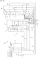
- An air separation unit 100 according to embodiment 1 illustrated in fig. 1A constitutes a low-pressure air separation unit.
- the air separation unit 100 comprises: a main heat exchanger 101, a first rectification column 2, a nitrogen condenser 3, a second rectification column 4, an expansion turbine 7 for feed air, a first heat exchanger 102, and a liquefied gas supply system 1.
- the first rectification column 2 comprises a column bottom portion 21, a rectification portion 22, and a column top portion 23.
- the second rectification column 4 comprises a column bottom portion 41, a rectification portion (lower rectification portion, first intermediate rectification portion 42, second intermediate rectification portion 43 in a stage above, and upper rectification portion), and a column top portion 44.
- the main heat exchanger 101 exchanges heat between feed air and another gas.
- a portion of the feed air drawn from the main heat exchanger 1 is introduced into the column bottom portion 21, which is a lower portion of the first rectification column 2, via a first feed air pipe L21.
- the remainder of the feed air is drawn from partway through the main heat exchanger 1 by means of a second feed air pipe L21a which branches from the first feed air pipe L21, and fed to the expansion turbine 7.
- the feed air used in the expansion turbine 7 is introduced into the second intermediate rectification portion 43 of the second rectification column 4 by means of the second feed air pipe L21a.
- a portion of the nitrogen gas drawn from the column top portion 23 of the first rectification column 2 by means of a nitrogen-rich substance drawing pipe L23b is fed to the nitrogen condenser 3, and after being cooled by means of cold heat of a refrigerant (oxygen-rich liquid) therein, the condensed nitrogen liquid is returned to the column top portion 23 of the first rectification column 2 by pipe L23.
- a refrigerant oxygen-rich liquid
- the remainder of the nitrogen liquid condensed in the condenser 3 is introduced into the column top portion 44 of the second rectification column 4 via a first branch pipe L23a branching from the nitrogen-rich substance drawing pipe L23.
- An oxygen-enriched liquid drawn from the column bottom portion 21 of the first rectification column 2 by means of an oxygen-enriched liquid drawing pipe L211 undergoes heat exchange with another gas in the first heat exchanger 102, and is then fed to the intermediate rectification portion 42 of the second rectification column 4.
- An oxygen-rich gas drawn from the column top portion 32 of the nitrogen condenser 3 by means of a low-pressure oxygen pipe L321 (or a waste gas pipe) is passed through the main heat exchanger 101 and then extracted (supplied externally) as low-pressure oxygen gas (or waste gas).
- An oxygen-rich gas drawn from the column top portion 32 of the nitrogen condenser 3 by means of a low-pressure oxygen pipe L32 is sent to the bottom of the second rectification column.
- Nitrogen gas drawn from the column top portion 44 of the second rectification column 4 by means of a product nitrogen gas pipe L44 is passed through the first heat exchanger 102 and passed through the main heat exchanger 101, and is then extracted as product nitrogen gas.
- the liquefied gas supply system 1 comprises: a first liquid feed pump 11 operable in a low-pressure operating mode or a high-pressure operating mode; a second liquid feed pump operable in a low-pressure operating mode or a high-pressure operating mode; and a control unit 15 for controlling the first liquid feed pump 11 and the second liquid feed pump 12 in the low-pressure operating mode and/or the high-pressure operating mode.
- Liquefied oxygen is drawn from the column bottom portion 41 of the second rectification column 4 by means of a first drawing pipe L1, and fed downstream to suit a predetermined purpose by means of the first liquid feed pump 11 and the second liquid feed pump 12.
- the low-pressure operating mode is determined, for example, by totalling a pressure on the refrigerant side (liquid oxygen side) of the nitrogen condenser 3 or in the second rectification column 4, a pressure corresponding to a lift height required to supply a liquid from the first liquid feed pump 11 or the second liquid feed pump 12 to the refrigerant side of the nitrogen condenser 3, and pipe pressure loss.
- the high-pressure operating mode is determined, for example, when a liquid is to be supplied to a supply destination, by totalling an operating pressure at the supply destination, a pressure corresponding to a lift height from the pump to the supply destination, and pipe pressure loss.
- the high-pressure operating mode is determined, when the liquid is vaporized for supply to the supply destination as a gas, by totalling a pressure corresponding to the lift height from the pump to a liquid vaporization point and pipe pressure loss with the pressure at the supply destination.
- the low pressure is 1.5-5 barA and the high-pressure is 5-20 barA, in terms of rectification column pressure, for example.
- the first drawing pipe L1 branches into a first branch pipe L11 and a second branch pipe L12 to feed liquefied oxygen.
- the first branch pipe L11 communicates with the nitrogen condenser 3, via a first removal point of pipe L13.
- the control unit 15 controls the first liquid feed pump 11 in the low-pressure operating mode so that a portion of branched first liquefied oxygen (corresponding to a first liquefied gas) is fed to the nitrogen condenser 3 as a circulation liquid (for the purpose of a refrigerant) (first circulation liquid in-feed processing).
- a first gate valve V1 and a third gate valve V3 provided in the first branch pipe L11 are controlled to an open state by means of the control unit 15.
- the second branch pipe L12 extends as far as the main heat exchanger 101.
- the control unit 15 controls the second liquid feed pump 12 in the high-pressure operating mode so that second liquefied oxygen (corresponding to a second liquefied gas) fed by the second branch pipe L12 undergoes heat exchange with another gas and is then extracted as product oxygen gas (first product liquid in-feed processing).
- a fifth gate valve V5 provided in the second branch pipe L12 is controlled to an open state by means of the control unit 15.
- a product liquid branch pipe L13 branching from the first branch pipe L11 merges with the second branch pipe L12 via a third removal point.
- a fourth gate valve V4 provided upstream from a merging position and downstream of a fourth removal point thereof is controlled to a closed state by means of the control unit 15.
- pipes L12, L13 merge.
- pipe L13 does not necessarily exist downstream of the first removal point.
- pipes L12 and L13 do not necessarily merge upstream of the heat exchanger, so that the liquid from pumps 11, 12 could be vaporised independently.
- the control unit 15 feeds the first liquefied oxygen to the nitrogen condenser 3 using the first liquid feed pump 11 which is in the low-pressure operating mode, and at the same time feeds a portion (W1) of the second liquefied oxygen to the nitrogen condenser 3 also using the second liquid feed pump 12 which is in the high-pressure operating mode (second circulation liquid in-feed processing).
- the control unit 15 opens the second gate valve V2 to cause the portion (W1) of the second liquefied oxygen to merge into the first branch pipe L11 through the circulation branch pipe L14. Furthermore, the control unit 15 feeds the remainder (W2) of the second liquefied oxygen to the main heat exchanger 101, after which it is extracted as product oxygen gas (second product liquid in-feed processing).
- the portion W1 corresponds to between 3 and 50% or even between 3 and 15%, preferably between 5 and 10% of the flowrate of the liquid at the first liquid pressure sent from the first pump 11 to the condenser section 3 in normal operation.
- the control unit 15 controls the amount of circulation liquid and the amount of product oxygen gas by adjusting opening/closing or flow rate of the second gate valve V2.
- the molar flowrate of liquid sent from the first pump to the condenser is at least five times, preferably at least eight times higher than the molar flowrate of liquid sent from the first pump to the heat exchanger; for example 95% of the liquid from the first pump 11 is sent to condenser 31 and 5% of the liquid from the first pump 11 is sent to the heat exchanger 101.
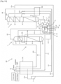
- An air separation unit 100 according to embodiment 2 illustrated in fig. 1B comprises first and second return pipes L16, L17, in addition to the components of embodiment 1.
- the same component reference numbers denote the same functions, and components having additional functions or different functions will be described in particular.
- the first return pipe L16 branches from the first branch pipe L11 downstream from the first liquid feed pump 11 and communicates with the column bottom portion 41 of the second rectification column 4.
- a sixth gate valve V6 is provided in the first return pipe L16. Opening/closing and flow rate of the sixth gate valve V6 are controlled and a return amount of the first liquefied oxygen is adjusted by means of the control unit 15.
- the first return pipe L17 branches from the second branch pipe L12 downstream from the second liquid feed pump 12 and communicates with the column bottom portion 41 of the second rectification column 4.
- a seventh gate valve V7 is provided in the second return pipe L17. Opening/closing or flow rate of the seventh gate valve V7 is controlled and a return amount of the second liquefied oxygen is adjusted by means of the control unit 15.
- An air separation unit 100 according to embodiment 3 illustrated in fig. 1C comprises a liquid level measurement unit F1 for the column bottom portion 41 of the second rectification column 4 and/or a flow rate measurement unit F2 for the product oxygen gas, in addition to the components of embodiment 1 or 2.
- the same component reference numbers denote the same functions, and components having additional functions or different functions will be described in particular.
- the liquid level measuring unit F1 measures an amount of liquefied oxygen in the column bottom portion 41 of the second rectification column 4.
- the control unit 15 controls a feed amount of the first liquefied oxygen by means of the first liquid feed pump 11, correspondingly with the measurement data. Furthermore, the control unit 15 controls a feed amount of the second liquefied oxygen by means of the second liquid feed pump 12 correspondingly with the measurement data.
- the flow rate measurement unit F2 is provided in the second branch pipe L12 downstream from the main heat exchanger 101, and measures the flow rate of product oxygen gas for a demand destination.
- the control unit 15 controls the feed amount of the first liquefied oxygen (the amount of circulation liquid which is fed by means of the first liquid feed pump 11, and the feed amount of the second liquefied oxygen (feed amount of the circulation liquid and amount of product oxygen gas) by means of the second liquid feed pump 12, correspondingly with the measurement data.
- the air separation unit 100 may comprise both the liquid level measurement unit F1 and the flow rate measurement unit F2, or may comprise either one thereof.
- the control unit 15 may operate the second liquid feed pump 12, which is in the high-pressure operating mode, at the minimum flow rate, and may operate the first liquid feed pump 11, which is in the low-pressure operating mode, so as to respond to process fluctuations.
- An air separation unit 100 according to embodiment 4 illustrated in fig. 1D is in accordance with the configurations of embodiments 1, 2 and 3, but has a different pipe configuration in the liquefied gas supply system 1.
- the same component reference numbers denote the same functions, and components having additional functions or different functions will be described in particular.
- the first branch pipe L11 communicates with the nitrogen condenser 3 and feeds the liquefied oxygen to the nitrogen condenser 3 as a circulation liquid.
- a gate valve V11 is provided in the first branch pipe L11.
- the fourth gate valve V4 is provided in the product liquid branch pipe L13 which branches from the first branch pipe L11 at a position upstream from the gate valve V11. The gate valve V11 is opened and the fourth gate valve V4 is closed, whereby the first liquefied oxygen is fed to the nitrogen condenser 3 by means of the first liquid feed pump 11.
- the second branch pipe L12 extends to the main heat exchanger 101 and feeds liquefied oxygen.
- the fifth gate valve V5 is provided in the second branch pipe L12.
- a gate valve V12 is provided in the circulation branch pipe L14.
- the gate valve V12 is closed and the fifth gate valve V5 is opened, whereby the second liquefied oxygen is fed only to the main heat exchanger 101 by means of the second liquid feed pump 12. Meanwhile, the gate valve V12 is opened and the fifth gate valve V5 is also opened, whereby a portion of the second liquefied oxygen (W1) is fed to the nitrogen condenser 3, and the remainder (W2) thereof is fed to the main heat exchanger 101.
- the first branch pipe L11 and the circulation branch pipe L14 do not merge, it is possible to suppress turbulence which would be at risk of occurring inside the pipes due to a liquid flow from high-pressure lines to low-pressure lines.
- Embodiment 5 illustrated in fig. 1D which is in accordance with embodiments 1, 2, 3 and 4, comprises first and second liquefied oxygen tanks T1, T2.
- the first liquefied oxygen tank T1 is a tank for extracting the first liquefied oxygen from the first branch pipe L11 as it runs to the nitrogen condenser 3, and for storing the first liquefied oxygen.
- the second liquefied oxygen tank T2 is a tank for extracting the second liquefied oxygen from the second branch pipe L12 as it runs to the main heat exchanger 101, and for storing the second liquefied oxygen.
- the first and second liquefied oxygen storage tanks T1, T2 may supply the liquefied oxygen as a product, and may be utilized as primary storage buffers.
- either one of the first liquid feed pump 11 and the second liquid feed pump 12 is stopped, and only the other is operated in the high-pressure operating mode, and opening/closing of the gate valves in the pipes is controlled.
- first liquid feed pump 11 is operated in the high-pressure operating mode
- second liquid feed pump 12 is operated in the high-pressure operating mode
- a portion of the second liquefied oxygen is fed to the nitrogen condenser 3 as a circulation liquid, and the remainder thereof is fed to the main heat exchanger 101.
- This portion may correspond to between 3 and 100% of the liquid sent from the first pump 11 to the condenser 3 in normal operation i.e. when the first and second pumps both operate, one sending liquid to the condenser and the other to heat exchanger.
- the control unit 15 closes the first gate valve V1 (or gate valve V11) and the fourth gate valve V4, and opens the second gate valve V2 and third gate valve V3 (or gate valve V12), and the fifth gate valve V5.
- the second liquid feed pump 12 is operated in the high-pressure operating mode.
- the control unit 15 closes the second gate valve V2 (gate valve V12) and the fifth gate valve V5, and opens the first gate valve V1 and third gate valve V3 (or gate valve V11), and the fourth gate valve V4.
- the first liquid feed pump 11 is operated in the high-pressure operating mode.
- An air separation unit 200 according to embodiment 7 illustrated in fig. 2 constitutes a high-pressure air separation unit.
- the same component reference numbers denote the same functions, and components having additional functions or different functions will be described in particular.
- the air separation unit 200 comprises: a main heat exchanger 101, a first rectification column 2, a nitrogen condenser 3, a second rectification column 4, an expansion turbine 71, a first heat exchanger 102, and a liquefied gas supply system 1.
- An oxygen-rich gas drawn from the column top portion 32 of the nitrogen condenser 3 is fed to the expansion turbine 71 after this gas has passed through a portion of the main heat exchanger 101 via a low-pressure oxygen line L3211.
- the oxygen-rich gas which has been used in the expansion turbine 71 is once again fed to the main heat exchanger 101 from where it is extracted as low-pressure oxygen gas (or waste gas).
- An expansion turbine 7 such as in embodiment 1 is not provided.
- An air separation unit 300 according to embodiment 8 illustrated in fig. 3 constitutes a high-pressure air separation unit (embodiment 7) comprising an argon rectification column.
- the same component reference numbers denote the same functions, and components having additional functions or different functions will be described in particular.
- the argon rectification column 5 comprises a column bottom portion 51, a rectification portion 52, and a column top portion 53.
- a first rectified substance e.g., an oxygen-rich gas drawn from the first intermediate rectification portion 42, or the rectification portion below, of the second rectification column 4 by means of an intermediate drawing pipe L42 is fed to the column bottom portion 51 of the argon rectification column 5 via the intermediate drawing pipe L42.
- a second rectified substance drawn from the column bottom portion 51 by means of a bottom portion drawing pipe L51 is fed to the first intermediate rectification portion 42 via the bottom portion drawing pipe L51.
- An oxygen-rich liquid drawn from the column bottom portion 21 of the first rectification column 2 passes through the first heat exchanger 102 via an oxygen-rich liquid drawing pipe L211, and is fed to the first intermediate rectification portion 42 of the second rectification column 4.
- the oxygen-rich liquid is fed to a refrigerant portion of a first condensing portion 6 by means of an oxygen-rich liquid drawing branch pipe L211a branching from the oxygen-rich liquid drawing pipe L211 at a position downstream from the first heat exchanger 102.
- An argon-rich substance drawn from the column top portion 53 of the argon rectification column 5 by means of an argon extraction pipe L53 is extracted as product argon via the argon extraction pipe L53.
- a separation pipe L53a separating from the argon extraction pipe L53 communicates with the first condensing portion 6 and feeds the argon-rich substance to the first condensing portion 6, where the argon-rich substance is condensed (liquefied) and returned to the column top portion 53 of the argon rectification column 5.
- a gas (oxygen-rich gas) drawn from the column top portion 62 of the first condensing portion 6 is fed to the first intermediate rectification portion 42 of the second rectification column 4 via a gas drawing pipe L62.
- the gas drawing pipe L62 merges with the oxygen-rich liquid drawing pipe L211, but this is not limiting.
- Additional refrigeration may be supplied for all the figures by the addition of liquid nitrogen to a column 2,4 from an external source (liquid assist).
Landscapes
- Engineering & Computer Science (AREA)
- Mechanical Engineering (AREA)
- General Engineering & Computer Science (AREA)
- Physics & Mathematics (AREA)
- Thermal Sciences (AREA)
- Health & Medical Sciences (AREA)
- Emergency Medicine (AREA)
- Separation By Low-Temperature Treatments (AREA)
- Pipeline Systems (AREA)
Abstract
Description
- The present disclosure relates to an air separation unit and to an air separation process for producing a product gas (e.g., nitrogen, argon or oxygen) from feed air by cryogenic distillation.
-
Patent Document 1 describes a pump process in a cryogenic air separation unit, where the same pump is used for different purposes in view of the need to reduce equipment costs.Patent Document 2 indicates that two or more pumps are provided from the point of view of reliable pump operations, and when an abnormal mode has been detected in one pump, the pump in which the abnormal mode has been detected is stopped, while output of the other is increased. Patent Document 3 describes a liquid oxygen pump for supplying liquid oxygen for the production of product oxygen gas, and a liquid oxygen pump for supplying liquid oxygen to be used as a refrigerant in a crude argon condenser. -
-
Patent Document 1 =JP 6257656 B2 -
Patent Document 2 =JP 5800620 B2 - Patent Document 3 =
WO 2021/230911 A1 - It is desirable for multiple pumps to be provided from the point of view of reliable pump operations, as in
Patent Document 2, so that continuous operation is possible even when there is a fault. On the other hand, providing pumps for different purposes not only leads to an increase in equipment costs because of the need to install a large amount of equipment, but also leads to more pipes and a larger installation area, hence greater construction costs and worse economics. Accordingly, there is a need to develop a highly reliable, low-cost pump configuration. - Conventionally, it is simple to devise a redundant pump configuration, in which multiple pressure values for each purpose are designed as operating points, and the pumps operate at the respective pressure values according to the purpose. In Patent Document 3, for example, a cryogenic air separation apparatus may have a configuration comprising both a process pump for supplying a reflux liquid to a rectification column and a vaporizer, and a product pump for delivering a product liquefied gas. In this case, the process pump needs power for a high/low difference at a liquid supply source and supply destination. The product pump needs power for a supply pressure, in addition to a high/low difference at the liquid supply source and supply destination or vaporization point. The required power per unit flow rate of the product pump tends to be greater than that of the process pump.
- In a redundant pump configuration, however, the pump design point is based on maximum pressure and flow rate, and the pumps can only be operated at a lower pressure or a lower throughput than the design point during steady operation, so that continuous operation is still possible in case there is a fault in one piece of equipment. Because the pumps have an operable range, if the demand for high-pressure purposes falls below a lower limit of the pump throughput, this produces energy loss in proportion to the difference between the demand for high-pressure purposes and the lower limit of the pump throughput.
- Furthermore, when a single pump serves as both the process pump and the product pump, as in
Patent Document 1, an outlet pressure of the pump needs to conform to product purposes, which causes an overpressure of the reflux liquid when the pump serves as the process pump. The energy of this overpressure produces heat penetration, which therefore leads to a loss of cold heat in a cryogenic air separation unit. A low-temperature refrigerant such as liquefied nitrogen is separately needed to replenish the loss of cold heat, and this increases costs. Furthermore,Patent Document 2 merely indicates that either one of the pumps is caused to function as a backup pump when there is an abnormality. - The objective of the present disclosure lies in providing a liquefied gas supply system for supplying liquefied gas for two purposes, which reduces power consumption by pumps and, as a result, reduces heat input to a cryogenic air separation process so that thermal efficiency can be improved, by virtue of a pump control method that minimises energy loss, and also in providing an air separation unit comprising the liquefied gas supply system.
- According to an object of the invention, there is provided an air separation unit comprising a first rectification column having an operating pressure which is a first pressure, a second rectification column having an operating pressure which is a second pressure, less than the first pressure, the first rectification column having a top condenser enclosed within a condenser section having an operating pressure which is the second pressure , a supply source which is a lower region of the second rectification column, the first rectification column and the second rectification column being placed side by side, a heat exchanger, means for sending feed air to the heat exchanger to be cooled and from the heat exchanger to the first rectification column, means for sending a gas from the condenser section to the bottom of the second rectification columns, a conduit for sending the gas removed from the top of the second rectification column to the heat exchanger to be warmed, a first pump and a second pump connected in parallel, the first pump being capable of producing liquid at a first liquid pressure and the second pump being capable of producing liquid at a second liquid pressure, higher than the first pressure, preferably at least 5 bars higher than the first pressure, each pump having an inlet connected to the supply source, a first outlet of the first pump being connected to a first outlet conduit, a second outlet of the second pump being connected to a second outlet conduit, the first outlet conduit being connected at a first removal point via a first valve to the condenser section and the second outlet conduit being connected at a second removal point via a second valve to the condenser section, the first outlet conduit being optionally connected at a third removal point via a third valve to the heat exchanger and the second outlet conduit being connected at a fourth removal point via a fourth valve to the heat exchanger.
- The unit may optionally include:
- means for mixing liquid removed via the first valve with liquid removed via the second valve and sending the mixed liquid in a common conduit to the condenser.
- the first valve and the second valve are connected to the condenser section via separate conduit means.
- the first removal point is upstream of the third removal point and/or the second removal point is upstream of the fourth removal point.
- a storage tank for storing liquid from a first or second pump upstream of the condenser section
- means for sending liquid from a first or second pump to the bottom of the second column
- means for sending liquid nitrogen from an external source to the first or second column
- a turbine and means for sending feed air or vaporised liquid oxygen from the condenser to the turbine
- According to another object of the invention, there is provided an air separation process using a first rectification column operating at a first pressure, a second rectification column operating at a second pressure, less than the first pressure, the first rectification column having a top condenser enclosed within a condenser section operating at the second pressure , a supply source which is a lower region of the second rectification column, the first rectification column and the second rectification column being placed side by side and a heat exchanger wherein feed air is sent to the heat exchanger to be cooled and then from the heat exchanger to the first rectification column, a gas from the condenser section is sent to the bottom of the second rectification column, a gas is removed from the top of the second rectification column, and sent to the heat exchanger to be warmed, wherein in normal operation, a first pump and a second pump connected in parallel are used to pressurise liquid from the bottom of the second rectification column, the first pump producing liquid at a first liquid pressure and the second pump producing liquid at a second liquid pressure, higher than the first liquid pressure, preferably at least 5 bars higher than the first liquid pressure, and the first pump sends liquid at the first liquid pressure to the condenser section and the second pump sends liquid at the second liquid pressure to the heat exchanger, wherein liquid at the second liquid pressure is at least sometimes sent from the second pump to the condenser section.
- According to optional features of the process:
- no liquid is sent in normal operation from the first pump to the heat exchanger.
- the liquid at the second liquid pressure sent from the second pump to the condenser section has a flowrate corresponding to between 3 and 100%, even between 3 and 50%, possibly between 3 and 15%, preferably between 5 and 10% of the flowrate of the liquid at the first liquid pressure sent from the first pump to the condenser section during normal operation.
- the liquid at the second pressure is not expanded between the second removal point and the condenser section.
- the liquid at the first liquid pressure and the liquid at the second liquid pressure are mixed upstream of the condenser section.
- the liquid at the first liquid pressure and the liquid at the second liquid pressure are not mixed upstream of the condenser section.
- the first and second liquid pressures differ by no more than 10 bars, preferably by no more than 7 bars.
- part of the refrigeration for the process is provided by liquid nitrogen from an external source.
- liquid at the second liquid pressure is sent from the second pump to the condenser section if the first pump is not operating.
- during normal operation liquid at the second liquid pressure is not sent from the second pump to the condenser section.
- liquid at the second liquid pressure is sent from the second pump to the condenser section if the first pump is operating at a reduced rate as compared to the rate during normal operation.
- the liquid at the second liquid pressure is reduced in pressure upstream of the condenser section.
- during normal operation, the molar flowrate of liquid sent from the first pump to the condenser is at least five times, preferably at least eight times higher than the molar flowrate of liquid sent from the first pump to the heat exchanger
- A liquefied gas supply system according to the present disclosure may comprise:
- a first liquid feed pump which is used to feed a first liquefied gas from a supply source (e.g., a column bottom portion of a rectification column, or a product liquefied gas storage tank, etc.) to a low-pressure supply destination (e.g., a rectification column, vaporizer, or condenser, etc.) for low-pressure purposes (e.g., for the purpose of circulation to the rectification column, for refrigerant purposes in the vaporizer or condenser);
- a second liquid feed pump which is used to feed a second liquefied gas from the supply source to a high-pressure supply destination (e.g., a heat exchanger or demand destination, etc.) for high-pressure purposes (e.g., delivery to the heat exchanger for product gas purposes, etc.); and
- a control unit configured to control the first liquid feed pump and the second liquid feed pump .
- The control unit may be configured to implement:
- first circulation liquid in-feed processing for feeding the first liquefied gas from the supply source to the low-pressure supply destination by means of the first liquid feed pump which is in a low-pressure operating mode; and
- first product liquid in-feed processing for feeding the second liquefied gas from the supply source to the high-pressure supply destination by means of the second liquid feed pump which is in a high-pressure operating mode.
- The control unit may be configured to implement:
- second circulation liquid in-feed processing for feeding the first liquefied gas from the supply source to the low-pressure supply destination by means of the first liquid feed pump which is in the low-pressure operating mode, and also for feeding in a portion W1of the second liquefied gas from the supply source to the low-pressure supply destination by means of the second liquid feed pump which is in the high-pressure operating mode; and
- second product liquid in-feed processing for feeding in the remainder W2of the second liquefied gas from the supply source to the high-pressure supply destination by means of the second liquid feed pump which is in the high-pressure operating mode (W1 + W2 = total in-feed amount from the second liquid feed pump).
- The control unit may be configured to implement:
- when the first liquid feed pump is in a stopped state, first liquid feed pump stoppage processing for feeding in a portion W21 of the second liquefied gas from the supply source to the high-pressure supply destination and for feeding in the remainder W22 of the second liquefied gas to the low-pressure supply destination by means of the second liquid feed pump (W21 + W22 = total in-feed amount from the second liquid feed pump).
- The control unit may be configured to implement:
- when the second liquid feed pump is in a stopped state, second liquid feed pump stoppage processing for feeding in a portion W11 of the first liquefied gas from the supply source to the low-pressure supply destination and for feeding in the remainder W12 of the product liquefied gas to the high-pressure supply destination by means of the first liquid feed pump (W11 + W12 = total in-feed amount from the first liquid feed pump).
- The control unit may be configured to control:
- an amount (amount per unit time) of the first liquefied gas fed from the supply source to the low-pressure supply destination by means of the first liquid feed pump , and may control an amount (amount per unit time) of the second liquefied gas fed from the supply source to the high-pressure supply destination by means of the second liquid feed pump, correspondingly with liquid amount data from a liquid amount measurement unit (e.g., a liquid level gauge, etc.) for measuring an amount of liquid at the supply source.
- The control unit may be configured to control:
- an amount (amount per unit time) of the first liquefied gas fed from the supply source to the low-pressure supply destination by means of the first liquid feed pump and may control an amount (amount per unit time) of the second liquefied gas fed from the supply source to the high-pressure supply destination by means of the second liquid feed pump , correspondingly with liquid amount data from a flow rate measurement unit (e.g., a flowmeter, etc.) for measuring an amount of liquid fed to the low-pressure supply destination.
- The control unit may control:
- an amount (amount per unit time) of the first liquefied gas fed from the supply source to the low-pressure supply destination by means of the first liquid feed pump , and may control an amount (amount per unit time) of the second liquefied gas fed from the supply source to the high-pressure supply destination by means of the second liquid feed pump , correspondingly with liquid amount data from a flow rate measurement unit (e.g., a flowmeter, etc.) for measuring an amount of liquid fed to the high-pressure supply destination, or gas amount data from a gas amount measurement unit for measuring a flow rate of product gas drawn from the high-pressure supply destination.
- The control unit may operate the second liquid feed pump , which is in a high-pressure operating mode, at a minimum flow rate, and may operate the first liquid feed pump , which is in a low-pressure operating mode, so as to respond to process fluctuations (e.g., fluctuation in a circulation liquid amount or fluctuation in a product gas amount).
- A pipe configuration may be such that a first low-pressure liquid feed line (first branch pipe ) running from the first liquid feed pump to the low-pressure supply destination, and a second low-pressure liquid feed line (circulation branch pipe L14) running from the second liquid feed pump to the low-pressure supply destination do not merge, or merge.
- The pipe configuration may be such that a first high-pressure liquid feed line (product liquid branch pipe L13 or first outlet conduit) running from the first liquid feed pump to the high-pressure supply destination, and a second high-pressure liquid feed line (second branch pipe L12 or second outlet conduit) running from the second liquid feed pump to the high-pressure supply destination may or may not merge..
- Valves may be provided in each of the liquid feed lines. The control unit may also control opening/closing of the valves and flow rate regulation, correspondingly with detection data of the liquid level gauge or the flow rate measurement unit. The liquefied gas supply system may comprise:
- a first return pipe for returning, to the supply source (column bottom portion of a second rectification column ), a portion of the product liquefied gas (liquefied oxygen) fed from the first liquid feed pump ; and
- a second return pipe for returning, to the supply source (column bottom portion of the second rectification column ) a portion of the product liquefied gas (liquefied oxygen) fed from the second liquid feed pump (12).
- The control unit may control the valves provided each of the pipes, and may regulate opening/closing thereof or flow rate.
- An air separation unit according to the present disclosure may optionally comprise:
- a main heat exchanger into which feed air is introduced;
- a first rectification column into which the feed air that has passed through the main heat exchanger is introduced;
- a nitrogen condenser for condensing a nitrogen-rich substance (in the form of a gas or a gas-liquid mixture) drawn from a column top portion or an upper stage of a rectification portion of the first rectification column ;
- a second rectification column having a column bottom portion for the introduction of an oxygen-rich gas drawn from a column top portion of the nitrogen condenser;
- an oxygen-enriched liquid drawing pipe for introducing an oxygen-enriched liquid drawn from the column bottom portion (21) of the first rectification column (2)
- into a rectification portion (first intermediate rectification portion 42) of the second rectification column ;
- an expansion turbine for expanding a portion of the feed air drawn from partway through the main heat exchanger);
- a second feed air pipe through which the feed air used in the expansion turbine is introduced into a rectification portion (second intermediate rectification portion of the second rectification column ;
- a nitrogen-rich substance introduction pipe for introducing a nitrogen-rich substance (in the form of a gas, a liquid, or a gas-liquid mixture) drawn from the column top portion of the first rectification column into a column top portion or an upper portion of a second rectification portion of the second rectification column ;
- a product nitrogen gas pipe for extracting product nitrogen gas that has been drawn from the column top portion of the second rectification column and passed through the main heat exchanger;
- a low-pressure oxygen pipe for causing an oxygen-rich gas drawn from the column top portion of the nitrogen condenser
- to pass through the main heat exchanger , and extracting low-pressure oxygen gas; and
- the liquefied gas supply system .
- An air separation unit according to different disclosure constitutes a high-pressure air separation unit, may comprise:
- a main heat exchanger into which feed air is introduced;
- a first rectification column into which the feed air that has passed through the main heat exchanger is introduced;
- a nitrogen condenser for condensing a nitrogen-rich substance (in the form of a gas or a gas-liquid mixture) drawn from a column top portion or an upper stage of a rectification portion of the first rectification column ;
- a second rectification column having a column bottom portion for the introduction of an oxygen-enriched gas drawn from a column top portion of the nitrogen condenser );
- an oxygen enriched liquid drawing pipe) for introducing an oxygen-enriched liquid drawn from the column bottom portion of the first rectification column into a rectification portion (first intermediate rectification portion ) of the second rectification column ;
- an expansion turbine into which an oxygen-rich gas drawn from the column top portion of the nitrogen condenser is introduced (via a low-pressure oxygen line) after passing through a portion of the main heat exchanger;
- a low-pressure oxygen line for causing the oxygen-rich gas used in the expansion turbine to pass through the main heat exchanger, and extracting low-pressure oxygen gas;
- a nitrogen-rich substance introduction pipe for introducing a nitrogen-rich substance (in the form of a gas, a liquid, or a gas-liquid mixture) drawn from the column top portion of the first rectification column into a column top portion or an upper portion of a second rectification portion of the second rectification column ;
- a product nitrogen gas line for extracting product nitrogen gas that has been drawn from the column top portion of the second rectification column and passed through the main heat exchanger; and
- the liquefied gas supply system .
- An air separation unit according to different disclosure constitutes a high-pressure air separation unit further provided with an argon rectification column, may comprise:
- a main heat exchanger into which feed air is introduced;
- a first rectification column into which the feed air that has passed through the main heat exchanger is introduced;
- a nitrogen condenser for condensing a nitrogen-rich substance (in the form of a gas or a gas-liquid mixture) drawn from a column top portion or an upper stage of a rectification portion of the first rectification column ;
- a second rectification column (4) having a column bottom portion for the introduction of an oxygen-rich gas drawn from a column top portion of the nitrogen condenser;
- an oxygen-enriched liquid drawing pipe for introducing an oxygen-enriched liquid drawn from the column bottom portion of the first rectification column into a rectification portion (first intermediate rectification portion 42) of the second rectification column ;
- an oxygen-enriched liquid drawing branch pipe for introducing an oxygen-enriched liquid drawn from the column bottom portion of the first rectification column into a column top portion of the argon rectification column or a refrigerant portion of a second condenser;
- an argon rectification column having a column bottom portion for the introduction of a first rectified substance drawn from a rectification portion (first intermediate rectification portion of the second rectification column ;
- a bottom portion drawing pipe for introducing a second rectified substance (e.g., an oxygen-rich liquid) drawn from the column bottom portion into the rectification portion of the second rectification column ;
- a first condensing portion for condensing (liquefying) an argon-rich substance (in the form of a gas or a gas-liquid mixture) drawn from a column top portion of the argon rectification column;
- a gas drawing pipe for introducing a gas (e.g., an oxygen-rich gas) drawn from a column top portion of the first condensing portion into the rectification portion of the second rectification column ;
- an expansion turbine into which an oxygen-rich gas drawn from the column top portion of the nitrogen condenser is introduced after passing through a portion of the main heat exchanger;
- a low-pressure oxygen line for causing the oxygen-rich gas used in the expansion turbine to pass through the main heat exchanger, and extracting low-pressure oxygen gas;
- a nitrogen-rich substance introduction pipe for introducing a nitrogen-rich substance (in the form of a gas, a liquid, or a gas-liquid mixture) drawn from the column top portion of the first rectification column into a column top portion or an upper portion of a second rectification portion of the second rectification column ;
- a product nitrogen gas line for extracting product nitrogen gas that has been drawn from the column top portion of the second rectification column and passed through the main heat exchanger; and
- the liquefied gas supply system.
- Pressure gauges and thermometers, etc. may be provided in the first and second rectification columns and in the argon rectification column .
- Gate valves, flow rate control valves, and expansion valves, etc. may be provided in each of the pipelines.
- Flowmeters, pressure gauges and thermometers, etc. may be provided in each of the pipelines.
- In the present disclosure, output pressures of the liquid feed pumps are generally determined by the pressure at the supply destination, a lift height from the pump to the supply destination, and pressure loss in the pipes. The liquid feed pumps are operable within a predetermined pressure range; in a low-pressure operating mode, the liquid feed pumps are operated at a low pressure conforming to the pressure at a low-pressure supply destination, and in a high-pressure operating mode, the liquid feed pumps are operated at a high-pressure conforming to the pressure at a high-pressure supply destination.
-
- [
Fig. 1A] Fig. 1A is a configuration example of an air separation unit according toembodiment 1. - [
Fig. 1B] Fig. 1B is a configuration example of an air separation unit according toembodiment 2. - [
Fig. 1C] Fig. 1C is a configuration example of an air separation unit according to embodiment 3. - [
Fig. 1D] Fig. 1D is a configuration example of an air separation unit according to embodiment 4. - [
Fig. 2] Fig. 2 is a configuration example of a air separation unit capable of operating of at higher pressures than the units ofFig. 1 . - [
Fig. 3] Fig. 3 is a configuration example of a high-pressure air separation unit comprising an argon rectification column. - Several embodiments of the present invention will be described below. The embodiments described below illustrate examples of the present invention. The present invention is in no way limited by the following embodiments, and also includes a number of variant modes which are implemented within a scope that does not alter the gist of the present invention. It should be noted that not all of the components described below are essential components of the present invention.
- In this specification, "upstream" and "downstream" are based on flows of gas (e.g., feed air, oxygen gas, nitrogen gas, argon gas) or various liquefied gases.
- An
air separation unit 100 according toembodiment 1 illustrated infig. 1A constitutes a low-pressure air separation unit. - The
air separation unit 100 comprises: amain heat exchanger 101, afirst rectification column 2, a nitrogen condenser 3, a second rectification column 4, an expansion turbine 7 for feed air, afirst heat exchanger 102, and a liquefiedgas supply system 1. - The
first rectification column 2 comprises acolumn bottom portion 21, arectification portion 22, and acolumn top portion 23. The second rectification column 4 comprises acolumn bottom portion 41, a rectification portion (lower rectification portion, firstintermediate rectification portion 42, secondintermediate rectification portion 43 in a stage above, and upper rectification portion), and acolumn top portion 44. - The
main heat exchanger 101 exchanges heat between feed air and another gas. A portion of the feed air drawn from themain heat exchanger 1 is introduced into thecolumn bottom portion 21, which is a lower portion of thefirst rectification column 2, via a first feed air pipe L21. - The remainder of the feed air is drawn from partway through the
main heat exchanger 1 by means of a second feed air pipe L21a which branches from the first feed air pipe L21, and fed to the expansion turbine 7. The feed air used in the expansion turbine 7 is introduced into the secondintermediate rectification portion 43 of the second rectification column 4 by means of the second feed air pipe L21a. - A portion of the nitrogen gas drawn from the
column top portion 23 of thefirst rectification column 2 by means of a nitrogen-rich substance drawing pipe L23b is fed to the nitrogen condenser 3, and after being cooled by means of cold heat of a refrigerant (oxygen-rich liquid) therein, the condensed nitrogen liquid is returned to thecolumn top portion 23 of thefirst rectification column 2 by pipe L23. - The remainder of the nitrogen liquid condensed in the condenser 3 is introduced into the
column top portion 44 of the second rectification column 4 via a first branch pipe L23a branching from the nitrogen-rich substance drawing pipe L23. - An oxygen-enriched liquid drawn from the
column bottom portion 21 of thefirst rectification column 2 by means of an oxygen-enriched liquid drawing pipe L211 undergoes heat exchange with another gas in thefirst heat exchanger 102, and is then fed to theintermediate rectification portion 42 of the second rectification column 4. - An oxygen-rich gas drawn from the
column top portion 32 of the nitrogen condenser 3 by means of a low-pressure oxygen pipe L321 (or a waste gas pipe) is passed through themain heat exchanger 101 and then extracted (supplied externally) as low-pressure oxygen gas (or waste gas). - An oxygen-rich gas drawn from the
column top portion 32 of the nitrogen condenser 3 by means of a low-pressure oxygen pipe L32 is sent to the bottom of the second rectification column. - Nitrogen gas drawn from the
column top portion 44 of the second rectification column 4 by means of a product nitrogen gas pipe L44 is passed through thefirst heat exchanger 102 and passed through themain heat exchanger 101, and is then extracted as product nitrogen gas. - The liquefied
gas supply system 1 comprises: a firstliquid feed pump 11 operable in a low-pressure operating mode or a high-pressure operating mode; a second liquid feed pump operable in a low-pressure operating mode or a high-pressure operating mode; and acontrol unit 15 for controlling the firstliquid feed pump 11 and the secondliquid feed pump 12 in the low-pressure operating mode and/or the high-pressure operating mode. - Liquefied oxygen is drawn from the
column bottom portion 41 of the second rectification column 4 by means of a first drawing pipe L1, and fed downstream to suit a predetermined purpose by means of the firstliquid feed pump 11 and the secondliquid feed pump 12. - The low-pressure operating mode is determined, for example, by totalling a pressure on the refrigerant side (liquid oxygen side) of the nitrogen condenser 3 or in the second rectification column 4, a pressure corresponding to a lift height required to supply a liquid from the first
liquid feed pump 11 or the secondliquid feed pump 12 to the refrigerant side of the nitrogen condenser 3, and pipe pressure loss. - The high-pressure operating mode is determined, for example, when a liquid is to be supplied to a supply destination, by totalling an operating pressure at the supply destination, a pressure corresponding to a lift height from the pump to the supply destination, and pipe pressure loss.
- The high-pressure operating mode is determined, when the liquid is vaporized for supply to the supply destination as a gas, by totalling a pressure corresponding to the lift height from the pump to a liquid vaporization point and pipe pressure loss with the pressure at the supply destination. The low pressure is 1.5-5 barA and the high-pressure is 5-20 barA, in terms of rectification column pressure, for example.
- The first drawing pipe L1 branches into a first branch pipe L11 and a second branch pipe L12 to feed liquefied oxygen. The first branch pipe L11 communicates with the nitrogen condenser 3, via a first removal point of pipe L13. The
control unit 15 controls the firstliquid feed pump 11 in the low-pressure operating mode so that a portion of branched first liquefied oxygen (corresponding to a first liquefied gas) is fed to the nitrogen condenser 3 as a circulation liquid (for the purpose of a refrigerant) (first circulation liquid in-feed processing). In this processing, a first gate valve V1 and a third gate valve V3 provided in the first branch pipe L11 are controlled to an open state by means of thecontrol unit 15. Furthermore, a circulation branch pipe L14 branching from the second branch pipe L12 merges with the first branch pipe L11. A second gate valve V2 provided upstream from a merging position thereof and downstream of a second removal point of pipe L12 is controlled to a closed state by means of thecontrol unit 15. - The second branch pipe L12 extends as far as the
main heat exchanger 101. Thecontrol unit 15 controls the secondliquid feed pump 12 in the high-pressure operating mode so that second liquefied oxygen (corresponding to a second liquefied gas) fed by the second branch pipe L12 undergoes heat exchange with another gas and is then extracted as product oxygen gas (first product liquid in-feed processing). In this processing, a fifth gate valve V5 provided in the second branch pipe L12 is controlled to an open state by means of thecontrol unit 15. Furthermore, a product liquid branch pipe L13 branching from the first branch pipe L11 merges with the second branch pipe L12 via a third removal point. A fourth gate valve V4 provided upstream from a merging position and downstream of a fourth removal point thereof is controlled to a closed state by means of thecontrol unit 15. - It will be seen that in this case the third and fourth removal points are in fact the same points since pipes L12, L13 merge. However pipe L13 does not necessarily exist downstream of the first removal point. Furthermore, pipes L12 and L13 do not necessarily merge upstream of the heat exchanger, so that the liquid from
pumps - The
control unit 15 feeds the first liquefied oxygen to the nitrogen condenser 3 using the firstliquid feed pump 11 which is in the low-pressure operating mode, and at the same time feeds a portion (W1) of the second liquefied oxygen to the nitrogen condenser 3 also using the secondliquid feed pump 12 which is in the high-pressure operating mode (second circulation liquid in-feed processing). Thecontrol unit 15 opens the second gate valve V2 to cause the portion (W1) of the second liquefied oxygen to merge into the first branch pipe L11 through the circulation branch pipe L14. Furthermore, thecontrol unit 15 feeds the remainder (W2) of the second liquefied oxygen to themain heat exchanger 101, after which it is extracted as product oxygen gas (second product liquid in-feed processing). - The portion W1 corresponds to between 3 and 50% or even between 3 and 15%, preferably between 5 and 10% of the flowrate of the liquid at the first liquid pressure sent from the
first pump 11 to the condenser section 3 in normal operation. - The
control unit 15 controls the amount of circulation liquid and the amount of product oxygen gas by adjusting opening/closing or flow rate of the second gate valve V2. - During normal operation, the molar flowrate of liquid sent from the first pump to the condenser is at least five times, preferably at least eight times higher than the molar flowrate of liquid sent from the first pump to the heat exchanger; for example 95% of the liquid from the
first pump 11 is sent tocondenser 31 and 5% of the liquid from thefirst pump 11 is sent to theheat exchanger 101. - An
air separation unit 100 according toembodiment 2 illustrated infig. 1B comprises first and second return pipes L16, L17, in addition to the components ofembodiment 1. The same component reference numbers denote the same functions, and components having additional functions or different functions will be described in particular. - The first return pipe L16 branches from the first branch pipe L11 downstream from the first
liquid feed pump 11 and communicates with thecolumn bottom portion 41 of the second rectification column 4. A sixth gate valve V6 is provided in the first return pipe L16. Opening/closing and flow rate of the sixth gate valve V6 are controlled and a return amount of the first liquefied oxygen is adjusted by means of thecontrol unit 15. - The first return pipe L17 branches from the second branch pipe L12 downstream from the second
liquid feed pump 12 and communicates with thecolumn bottom portion 41 of the second rectification column 4. A seventh gate valve V7 is provided in the second return pipe L17. Opening/closing or flow rate of the seventh gate valve V7 is controlled and a return amount of the second liquefied oxygen is adjusted by means of thecontrol unit 15. - An
air separation unit 100 according to embodiment 3 illustrated infig. 1C comprises a liquid level measurement unit F1 for thecolumn bottom portion 41 of the second rectification column 4 and/or a flow rate measurement unit F2 for the product oxygen gas, in addition to the components ofembodiment - The liquid level measuring unit F1 measures an amount of liquefied oxygen in the
column bottom portion 41 of the second rectification column 4. Thecontrol unit 15 controls a feed amount of the first liquefied oxygen by means of the firstliquid feed pump 11, correspondingly with the measurement data. Furthermore, thecontrol unit 15 controls a feed amount of the second liquefied oxygen by means of the secondliquid feed pump 12 correspondingly with the measurement data. - The flow rate measurement unit F2 is provided in the second branch pipe L12 downstream from the
main heat exchanger 101, and measures the flow rate of product oxygen gas for a demand destination. Thecontrol unit 15 controls the feed amount of the first liquefied oxygen (the amount of circulation liquid which is fed by means of the firstliquid feed pump 11, and the feed amount of the second liquefied oxygen (feed amount of the circulation liquid and amount of product oxygen gas) by means of the secondliquid feed pump 12, correspondingly with the measurement data. - The
air separation unit 100 may comprise both the liquid level measurement unit F1 and the flow rate measurement unit F2, or may comprise either one thereof. - The
control unit 15 may operate the secondliquid feed pump 12, which is in the high-pressure operating mode, at the minimum flow rate, and may operate the firstliquid feed pump 11, which is in the low-pressure operating mode, so as to respond to process fluctuations. - An
air separation unit 100 according to embodiment 4 illustrated infig. 1D is in accordance with the configurations ofembodiments gas supply system 1. The same component reference numbers denote the same functions, and components having additional functions or different functions will be described in particular. - The first branch pipe L11 communicates with the nitrogen condenser 3 and feeds the liquefied oxygen to the nitrogen condenser 3 as a circulation liquid. A gate valve V11 is provided in the first branch pipe L11. The fourth gate valve V4 is provided in the product liquid branch pipe L13 which branches from the first branch pipe L11 at a position upstream from the gate valve V11. The gate valve V11 is opened and the fourth gate valve V4 is closed, whereby the first liquefied oxygen is fed to the nitrogen condenser 3 by means of the first
liquid feed pump 11. - The second branch pipe L12 extends to the
main heat exchanger 101 and feeds liquefied oxygen. The fifth gate valve V5 is provided in the second branch pipe L12. The circulation branch pipe L14 branching from the second branch pipe L12 at a position upstream from the fifth gate valve V5 communicates with the nitrogen condenser 3. A gate valve V12 is provided in the circulation branch pipe L14. The gate valve V12 is closed and the fifth gate valve V5 is opened, whereby the second liquefied oxygen is fed only to themain heat exchanger 101 by means of the secondliquid feed pump 12. Meanwhile, the gate valve V12 is opened and the fifth gate valve V5 is also opened, whereby a portion of the second liquefied oxygen (W1) is fed to the nitrogen condenser 3, and the remainder (W2) thereof is fed to themain heat exchanger 101. - According to the configuration above, by virtue of the fact that the first branch pipe L11 and the circulation branch pipe L14 do not merge, it is possible to suppress turbulence which would be at risk of occurring inside the pipes due to a liquid flow from high-pressure lines to low-pressure lines.
- Embodiment 5 illustrated in
fig. 1D , which is in accordance withembodiments - The first liquefied oxygen tank T1 is a tank for extracting the first liquefied oxygen from the first branch pipe L11 as it runs to the nitrogen condenser 3, and for storing the first liquefied oxygen.
- The second liquefied oxygen tank T2 is a tank for extracting the second liquefied oxygen from the second branch pipe L12 as it runs to the
main heat exchanger 101, and for storing the second liquefied oxygen. - The first and second liquefied oxygen storage tanks T1, T2 may supply the liquefied oxygen as a product, and may be utilized as primary storage buffers.
- In embodiments 1-5, either one of the first
liquid feed pump 11 and the secondliquid feed pump 12 is stopped, and only the other is operated in the high-pressure operating mode, and opening/closing of the gate valves in the pipes is controlled. When only the firstliquid feed pump 11 is operated in the high-pressure operating mode, a portion of the first liquefied oxygen is fed to the nitrogen condenser 3 as a circulation liquid, and the remainder thereof is fed to themain heat exchanger 101. When only the secondliquid feed pump 12 is operated in the high-pressure operating mode, a portion of the second liquefied oxygen is fed to the nitrogen condenser 3 as a circulation liquid, and the remainder thereof is fed to themain heat exchanger 101. This portion may correspond to between 3 and 100% of the liquid sent from thefirst pump 11 to the condenser 3 in normal operation i.e. when the first and second pumps both operate, one sending liquid to the condenser and the other to heat exchanger. - When the first
liquid feed pump 11 has been stopped, thecontrol unit 15 closes the first gate valve V1 (or gate valve V11) and the fourth gate valve V4, and opens the second gate valve V2 and third gate valve V3 (or gate valve V12), and the fifth gate valve V5. The secondliquid feed pump 12 is operated in the high-pressure operating mode. - Meanwhile, when the second
liquid feed pump 12 has been stopped, thecontrol unit 15 closes the second gate valve V2 (gate valve V12) and the fifth gate valve V5, and opens the first gate valve V1 and third gate valve V3 (or gate valve V11), and the fourth gate valve V4. The firstliquid feed pump 11 is operated in the high-pressure operating mode. - An
air separation unit 200 according to embodiment 7 illustrated infig. 2 constitutes a high-pressure air separation unit. The same component reference numbers denote the same functions, and components having additional functions or different functions will be described in particular. - The
air separation unit 200 comprises: amain heat exchanger 101, afirst rectification column 2, a nitrogen condenser 3, a second rectification column 4, anexpansion turbine 71, afirst heat exchanger 102, and a liquefiedgas supply system 1. - An oxygen-rich gas drawn from the
column top portion 32 of the nitrogen condenser 3 is fed to theexpansion turbine 71 after this gas has passed through a portion of themain heat exchanger 101 via a low-pressure oxygen line L3211. The oxygen-rich gas which has been used in theexpansion turbine 71 is once again fed to themain heat exchanger 101 from where it is extracted as low-pressure oxygen gas (or waste gas). - An expansion turbine 7 such as in
embodiment 1 is not provided. - The configurations of embodiments 1-6 are applied to the liquefied
gas supply system 1. - An
air separation unit 300 according to embodiment 8 illustrated infig. 3 constitutes a high-pressure air separation unit (embodiment 7) comprising an argon rectification column. The same component reference numbers denote the same functions, and components having additional functions or different functions will be described in particular. - The argon rectification column 5 comprises a
column bottom portion 51, arectification portion 52, and acolumn top portion 53. A first rectified substance (e.g., an oxygen-rich gas) drawn from the firstintermediate rectification portion 42, or the rectification portion below, of the second rectification column 4 by means of an intermediate drawing pipe L42 is fed to thecolumn bottom portion 51 of the argon rectification column 5 via the intermediate drawing pipe L42. A second rectified substance drawn from thecolumn bottom portion 51 by means of a bottom portion drawing pipe L51 is fed to the firstintermediate rectification portion 42 via the bottom portion drawing pipe L51. - An oxygen-rich liquid drawn from the
column bottom portion 21 of thefirst rectification column 2 passes through thefirst heat exchanger 102 via an oxygen-rich liquid drawing pipe L211, and is fed to the firstintermediate rectification portion 42 of the second rectification column 4. The oxygen-rich liquid is fed to a refrigerant portion of a first condensing portion 6 by means of an oxygen-rich liquid drawing branch pipe L211a branching from the oxygen-rich liquid drawing pipe L211 at a position downstream from thefirst heat exchanger 102. - An argon-rich substance drawn from the
column top portion 53 of the argon rectification column 5 by means of an argon extraction pipe L53 is extracted as product argon via the argon extraction pipe L53. - A separation pipe L53a separating from the argon extraction pipe L53 communicates with the first condensing portion 6 and feeds the argon-rich substance to the first condensing portion 6, where the argon-rich substance is condensed (liquefied) and returned to the
column top portion 53 of the argon rectification column 5. - A gas (oxygen-rich gas) drawn from the
column top portion 62 of the first condensing portion 6 is fed to the firstintermediate rectification portion 42 of the second rectification column 4 via a gas drawing pipe L62. Infig. 3 , the gas drawing pipe L62 merges with the oxygen-rich liquid drawing pipe L211, but this is not limiting. - The configurations of embodiments 1-6 are applied to the liquefied
gas supply system 1. -
- (1) In embodiments 1-8, the liquefied
gas supply system 1 comprises the two liquid feed pumps, i.e., the first and second liquid feed pumps, but this is not limiting, and three or more liquid feed pumps may be provided. - (2) Application of the liquefied
gas supply system 1 is not limited to the air separation units of embodiments 1-8, and it may also be applied to other air separation units. -
- 1 Liquefied gas supply system
- 2 First rectification column
- 3 Nitrogen condenser
- 4 Second rectification column
- 5 Argon rectification column 7 Expansion turbine
- 11 First liquid feedpump
- 12 Second liquid feed pump
- 15 Control unit
- 100 Air separation unit
- 101 Main heat exchanger
- Additional refrigeration may be supplied for all the figures by the addition of liquid nitrogen to a
column 2,4 from an external source (liquid assist). - The present invention solves above technical problems by the configuration characterized as follows.
Case Invention Dedicated pump arrangement with one pump feeding the condenser only and another feeding the heat exchanger only Shared pumps ( JP6257656B2 Heat leak (Mcal/h) 20 19 22 Compensation by N2 liquid assist (kW) 6 Base 15 Investment (mJPY) -1 -7 -1 NPV ( mJPY) -4.9 -9.2 -10.7
Claims (15)
- Air separation unit comprising a first rectification column (2) having an operating pressure which is a first pressure, a second rectification column (4) having an operating pressure which is a second pressure, less than the first pressure, the first rectification column having a top condenser (31) enclosed within a condenser section (3) having an operating pressure which is the second pressure , a supply source (41) which is a lower region of the second rectification column, the first rectification column and the second rectification column being placed side by side, a heat exchanger (101), means for sending feed air (L21) to the heat exchanger to be cooled and from the heat exchanger to the first rectification column, means for sending a gas (L32) from the condenser section to the bottom of the second rectification columns, a conduit for sending the gas (L44) removed from the top of the second rectification column to the heat exchanger to be warmed, a first pump (11) and a second pump (12) connected in parallel, the first pump being capable of producing liquid at a first liquid pressure and the second pump being capable of producing liquid at a second liquid pressure, higher than the first pressure, preferably at least 5 bars higher than the first pressure, each pump having an inlet connected to the supply source, a first outlet of the first pump being connected to a first outlet conduit (L13), a second outlet of the second pump being connected to a second outlet conduit (L12), the first outlet conduit being connected at a first removal point via a first valve (V1) to the condenser section and the second outlet conduit being connected at a second removal point via a second valve (V2) to the condenser section, the first outlet conduit being optionally connected at a third removal point via a third valve (V4) to the heat exchanger and the second outlet conduit being connected at a fourth removal point via a fourth valve (V5) to the heat exchanger.
- Unit according to Claim 1 comprising means for mixing liquid removed via the first valve (V1) with liquid removed via the second valve (V2) and sending the mixed liquid in a common conduit (L11) to the condenser (31).
- Unit according to Claim 1 wherein the first valve and the second valve are connected to the condenser section (3) via separate conduit means (L11, L14).
- Unit according to any preceding claim wherein the first removal point is upstream of the third removal point and/or the second removal point is upstream of the fourth removal point.
- Air separation process using a first rectification column (2) operating at a first pressure, a second rectification column (4) operating at a second pressure, less than the first pressure, the first rectification column having a top condenser (31) enclosed within a condenser section (3) operating at the second pressure , a supply source (41) which is a lower region of the second rectification column, the first rectification column and the second rectification column being placed side by side and a heat exchanger (101) wherein feed air is sent to the heat exchanger to be cooled and then from the heat exchanger to the first rectification column, a gas (L32) from the condenser section is sent to the bottom of the second rectification column, a gas (L44) is removed from the top of the second rectification column, and sent to the heat exchanger to be warmed, wherein in normal operation, a first pump (11) and a second pump (12) connected in parallel are used to pressurise liquid from the bottom of the second rectification column, the first pump producing liquid at a first liquid pressure and the second pump producing liquid at a second liquid pressure, higher than the first liquid pressure, preferably at least 5 bars higher than the first liquid pressure, and the first pump sends liquid at the first liquid pressure to the condenser section and the second pump sends liquid at the second liquid pressure to the heat exchanger, wherein liquid at the second liquid pressure is at least sometimes sent from the second pump to the condenser section.
- Process according to Claim 5 wherein no liquid is sent in normal operation from the first pump (11) to the heat exchanger (101).
- Process according to Claim 5 or 6 wherein the liquid at the second liquid pressure sent from the second pump (12) to the condenser section has a flowrate corresponding to between 3 and 100%, or to between 3 and 50% or even between 3 and 15%, preferably between 5 and 10% of the flowrate of the liquid at the first liquid pressure sent from the first pump (11) to the condenser section (3) in normal operation.
- Process according to one of Claims 5 to 7 wherein the liquid at the second pressure is not expanded between the second removal point and the condenser section (3).
- Process according to one of Claims 5 to 8 wherein the liquid at the first liquid pressure and the liquid at the second liquid pressure are mixed upstream of the condenser section (3).
- Process according to one of Claims 5 to 9 wherein the first and second liquid pressures differ by no more than 10 bars, preferably by no more than 7 bars.
- Process according to one of Claims 5 to 10 wherein part of the refrigeration for the process is provided by liquid nitrogen from an external source.
- Process according to one of Claims 5 to 11 wherein liquid at the second liquid pressure is sent from the second pump (12) to the condenser section (3) if the first pump (11) is not operating.
- Process according to Claim 12 wherein during normal operation liquid at the second liquid pressure is not sent from the second pump (12) to the condenser section (3).
- Process according to one of Claims 5 to 11 wherein liquid at the second liquid pressure is sent from the second pump (12) to the condenser section (3) if the first pump (11) is operating at a reduced rate as compared to the rate during normal operation.
- Process according to Claim 12 or 14 wherein the liquid at the second liquid pressure is reduced in pressure upstream of the condenser section (3).
Applications Claiming Priority (1)
| Application Number | Priority Date | Filing Date | Title |
|---|---|---|---|
| JP2023079342A JP2024163591A (en) | 2023-05-12 | 2023-05-12 | Liquefied gas supply system and air separation unit equipped with same |
Publications (2)
| Publication Number | Publication Date |
|---|---|
| EP4464961A1 true EP4464961A1 (en) | 2024-11-20 |
| EP4464961A3 EP4464961A3 (en) | 2025-02-19 |
Family
ID=91030196
Family Applications (1)
| Application Number | Title | Priority Date | Filing Date |
|---|---|---|---|
| EP24174443.2A Pending EP4464961A3 (en) | 2023-05-12 | 2024-05-07 | Air separation unit and process for producing a product gas from feed air by cryogenic distillation |
Country Status (4)
| Country | Link |
|---|---|
| US (1) | US20240377130A1 (en) |
| EP (1) | EP4464961A3 (en) |
| JP (1) | JP2024163591A (en) |
| CN (1) | CN118935916A (en) |
Citations (4)
| Publication number | Priority date | Publication date | Assignee | Title |
|---|---|---|---|---|
| DE10213212A1 (en) * | 2002-03-25 | 2002-10-17 | Linde Ag | Air fractionation plant in which product stream is split, carries out all compression stages in common dual flow pump |
| JP5800620B2 (en) | 2011-07-25 | 2015-10-28 | 日本エア・リキード株式会社 | Low temperature substance transfer device and low temperature liquefied gas supply system using the same |
| JP6257656B2 (en) | 2013-03-06 | 2018-01-10 | リンデ アクチエンゲゼルシャフトLinde Aktiengesellschaft | Air separation device, method for obtaining a product containing argon, and method for building an air separation device |
| WO2021230911A1 (en) | 2020-05-15 | 2021-11-18 | Praxair Technology, Inc. | Integrated nitrogen liquefier for a nitrogen and argon producing cryogenic air separation unit |
Family Cites Families (4)
| Publication number | Priority date | Publication date | Assignee | Title |
|---|---|---|---|---|
| US3214926A (en) * | 1963-04-15 | 1965-11-02 | Philips Corp | Method of producing liquid oxygen and/or liquid nitrogen |
| DE10111428A1 (en) * | 2001-03-09 | 2002-09-12 | Linde Ag | Method and device for separating a gas mixture with emergency operation |
| DE10153252A1 (en) * | 2001-10-31 | 2003-05-15 | Linde Ag | Process for recovering krypton and/or xenon by low temperature decomposition of air, comprises passing compressed purified process air to a rectifier system, removing a fraction containing krypton and xenon, and further processing |
| CN107580670B (en) * | 2015-03-13 | 2020-02-28 | 林德股份公司 | Apparatus for producing oxygen by cryogenic air separation |
-
2023
- 2023-05-12 JP JP2023079342A patent/JP2024163591A/en active Pending
-
2024
- 2024-04-10 CN CN202410426876.6A patent/CN118935916A/en active Pending
- 2024-05-07 EP EP24174443.2A patent/EP4464961A3/en active Pending
- 2024-05-10 US US18/660,949 patent/US20240377130A1/en active Pending
Patent Citations (4)
| Publication number | Priority date | Publication date | Assignee | Title |
|---|---|---|---|---|
| DE10213212A1 (en) * | 2002-03-25 | 2002-10-17 | Linde Ag | Air fractionation plant in which product stream is split, carries out all compression stages in common dual flow pump |
| JP5800620B2 (en) | 2011-07-25 | 2015-10-28 | 日本エア・リキード株式会社 | Low temperature substance transfer device and low temperature liquefied gas supply system using the same |
| JP6257656B2 (en) | 2013-03-06 | 2018-01-10 | リンデ アクチエンゲゼルシャフトLinde Aktiengesellschaft | Air separation device, method for obtaining a product containing argon, and method for building an air separation device |
| WO2021230911A1 (en) | 2020-05-15 | 2021-11-18 | Praxair Technology, Inc. | Integrated nitrogen liquefier for a nitrogen and argon producing cryogenic air separation unit |
Also Published As
| Publication number | Publication date |
|---|---|
| EP4464961A3 (en) | 2025-02-19 |
| US20240377130A1 (en) | 2024-11-14 |
| CN118935916A (en) | 2024-11-12 |
| JP2024163591A (en) | 2024-11-22 |
Similar Documents
| Publication | Publication Date | Title |
|---|---|---|
| TWI821181B (en) | Gas production system | |
| US11846468B2 (en) | Method and unit for low-temperature air separation | |
| US20060037357A1 (en) | Process and system for obtaining a gaseous pressure product by the cryogenic separation of air | |
| HU220018B (en) | Method and apparatus for air ractification | |
| JPH10259990A (en) | Method and plant for supplying a variable flow of gas from air | |
| US9733014B2 (en) | Method and device for obtaining compressed oxygen and compressed nitrogen by the low-temperature separation of air | |
| TWI797361B (en) | Air separation device | |
| KR101042097B1 (en) | Pressurized gas supply method and apparatus | |
| CA2375570C (en) | Process and apparatus for separating a gas mixture with emergency operation | |
| JPH0618162A (en) | Liquid transfer method and rectification equipment using the method | |
| US20130299337A1 (en) | Method and equipment for purifying a gas stream | |
| US20240377130A1 (en) | Liquefied gas supply system and air separation unit comprising same | |
| US12158303B2 (en) | Method for obtaining one or more air products and air separation system | |
| CN103080678B (en) | Method and apparatus for separating air by cryogenic distillation | |
| US20130098106A1 (en) | Apparatus and process for separating air by cryogenic distillation | |
| US20240393043A1 (en) | Method for the low-temperature separation of air and air separation plant | |
| US20260092735A1 (en) | Air separation unit | |
| CN216953768U (en) | Integrated system of air separation plant | |
| JP3249640U (en) | Air Separation Unit | |
| US6233970B1 (en) | Process for delivery of oxygen at a variable rate | |
| US20250264274A1 (en) | Air separation unit | |
| JP3254817U (en) | air separation unit | |
| JP3244654U (en) | air separation equipment | |
| CN117889611A (en) | Nitrogen supply system and nitrogen supply method | |
| JP2007212039A (en) | Nitrogen gas production equipment for combustible gas replacement |
Legal Events
| Date | Code | Title | Description |
|---|---|---|---|
| PUAI | Public reference made under article 153(3) epc to a published international application that has entered the european phase |
Free format text: ORIGINAL CODE: 0009012 |
|
| STAA | Information on the status of an ep patent application or granted ep patent |
Free format text: STATUS: THE APPLICATION HAS BEEN PUBLISHED |
|
| AK | Designated contracting states |
Kind code of ref document: A1 Designated state(s): AL AT BE BG CH CY CZ DE DK EE ES FI FR GB GR HR HU IE IS IT LI LT LU LV MC ME MK MT NL NO PL PT RO RS SE SI SK SM TR |
|
| PUAB | Information related to the publication of an a document modified or deleted |
Free format text: ORIGINAL CODE: 0009199EPPU |
|
| PUAF | Information related to the publication of a search report (a3 document) modified or deleted |
Free format text: ORIGINAL CODE: 0009199SEPU |
|
| D17D | Deferred search report published (deleted) | ||
| PUAL | Search report despatched |
Free format text: ORIGINAL CODE: 0009013 |
|
| AK | Designated contracting states |
Kind code of ref document: A3 Designated state(s): AL AT BE BG CH CY CZ DE DK EE ES FI FR GB GR HR HU IE IS IT LI LT LU LV MC ME MK MT NL NO PL PT RO RS SE SI SK SM TR |
|
| RIC1 | Information provided on ipc code assigned before grant |
Ipc: F25J 1/00 20060101AFI20250113BHEP |
|
| STAA | Information on the status of an ep patent application or granted ep patent |
Free format text: STATUS: REQUEST FOR EXAMINATION WAS MADE |
|
| 17P | Request for examination filed |
Effective date: 20250819 |
|
| STAA | Information on the status of an ep patent application or granted ep patent |
Free format text: STATUS: EXAMINATION IS IN PROGRESS |
|
| 17Q | First examination report despatched |
Effective date: 20260216 |