EP4464949A1 - Method and system for controlling a fresh air intake of an air handling unit of an hvac system - Google Patents
Method and system for controlling a fresh air intake of an air handling unit of an hvac system Download PDFInfo
- Publication number
- EP4464949A1 EP4464949A1 EP24172206.5A EP24172206A EP4464949A1 EP 4464949 A1 EP4464949 A1 EP 4464949A1 EP 24172206 A EP24172206 A EP 24172206A EP 4464949 A1 EP4464949 A1 EP 4464949A1
- Authority
- EP
- European Patent Office
- Prior art keywords
- heating
- flow rate
- measure
- air flow
- flow
- Prior art date
- Legal status (The legal status is an assumption and is not a legal conclusion. Google has not performed a legal analysis and makes no representation as to the accuracy of the status listed.)
- Pending
Links
Images




Classifications
-
- F—MECHANICAL ENGINEERING; LIGHTING; HEATING; WEAPONS; BLASTING
- F24—HEATING; RANGES; VENTILATING
- F24F—AIR-CONDITIONING; AIR-HUMIDIFICATION; VENTILATION; USE OF AIR CURRENTS FOR SCREENING
- F24F11/00—Control or safety arrangements
- F24F11/70—Control systems characterised by their outputs; Constructional details thereof
- F24F11/72—Control systems characterised by their outputs; Constructional details thereof for controlling the supply of treated air, e.g. its pressure
- F24F11/74—Control systems characterised by their outputs; Constructional details thereof for controlling the supply of treated air, e.g. its pressure for controlling air flow rate or air velocity
- F24F11/77—Control systems characterised by their outputs; Constructional details thereof for controlling the supply of treated air, e.g. its pressure for controlling air flow rate or air velocity by controlling the speed of ventilators
-
- F—MECHANICAL ENGINEERING; LIGHTING; HEATING; WEAPONS; BLASTING
- F24—HEATING; RANGES; VENTILATING
- F24F—AIR-CONDITIONING; AIR-HUMIDIFICATION; VENTILATION; USE OF AIR CURRENTS FOR SCREENING
- F24F11/00—Control or safety arrangements
- F24F11/62—Control or safety arrangements characterised by the type of control or by internal processing, e.g. using fuzzy logic, adaptive control or estimation of values
- F24F11/63—Electronic processing
-
- F—MECHANICAL ENGINEERING; LIGHTING; HEATING; WEAPONS; BLASTING
- F24—HEATING; RANGES; VENTILATING
- F24F—AIR-CONDITIONING; AIR-HUMIDIFICATION; VENTILATION; USE OF AIR CURRENTS FOR SCREENING
- F24F11/00—Control or safety arrangements
- F24F11/70—Control systems characterised by their outputs; Constructional details thereof
- F24F11/72—Control systems characterised by their outputs; Constructional details thereof for controlling the supply of treated air, e.g. its pressure
-
- F—MECHANICAL ENGINEERING; LIGHTING; HEATING; WEAPONS; BLASTING
- F24—HEATING; RANGES; VENTILATING
- F24F—AIR-CONDITIONING; AIR-HUMIDIFICATION; VENTILATION; USE OF AIR CURRENTS FOR SCREENING
- F24F11/00—Control or safety arrangements
- F24F11/70—Control systems characterised by their outputs; Constructional details thereof
- F24F11/72—Control systems characterised by their outputs; Constructional details thereof for controlling the supply of treated air, e.g. its pressure
- F24F11/74—Control systems characterised by their outputs; Constructional details thereof for controlling the supply of treated air, e.g. its pressure for controlling air flow rate or air velocity
-
- F—MECHANICAL ENGINEERING; LIGHTING; HEATING; WEAPONS; BLASTING
- F24—HEATING; RANGES; VENTILATING
- F24F—AIR-CONDITIONING; AIR-HUMIDIFICATION; VENTILATION; USE OF AIR CURRENTS FOR SCREENING
- F24F11/00—Control or safety arrangements
- F24F11/70—Control systems characterised by their outputs; Constructional details thereof
- F24F11/80—Control systems characterised by their outputs; Constructional details thereof for controlling the temperature of the supplied air
- F24F11/81—Control systems characterised by their outputs; Constructional details thereof for controlling the temperature of the supplied air by controlling the air supply to heat-exchangers or bypass channels
-
- F—MECHANICAL ENGINEERING; LIGHTING; HEATING; WEAPONS; BLASTING
- F24—HEATING; RANGES; VENTILATING
- F24F—AIR-CONDITIONING; AIR-HUMIDIFICATION; VENTILATION; USE OF AIR CURRENTS FOR SCREENING
- F24F11/00—Control or safety arrangements
- F24F11/70—Control systems characterised by their outputs; Constructional details thereof
- F24F11/80—Control systems characterised by their outputs; Constructional details thereof for controlling the temperature of the supplied air
- F24F11/83—Control systems characterised by their outputs; Constructional details thereof for controlling the temperature of the supplied air by controlling the supply of heat-exchange fluids to heat-exchangers
-
- F—MECHANICAL ENGINEERING; LIGHTING; HEATING; WEAPONS; BLASTING
- F24—HEATING; RANGES; VENTILATING
- F24F—AIR-CONDITIONING; AIR-HUMIDIFICATION; VENTILATION; USE OF AIR CURRENTS FOR SCREENING
- F24F13/00—Details common to, or for air-conditioning, air-humidification, ventilation or use of air currents for screening
- F24F13/08—Air-flow control members, e.g. louvres, grilles, flaps or guide plates
- F24F13/10—Air-flow control members, e.g. louvres, grilles, flaps or guide plates movable, e.g. dampers
- F24F13/14—Air-flow control members, e.g. louvres, grilles, flaps or guide plates movable, e.g. dampers built up of tilting members, e.g. louvre
-
- F—MECHANICAL ENGINEERING; LIGHTING; HEATING; WEAPONS; BLASTING
- F24—HEATING; RANGES; VENTILATING
- F24F—AIR-CONDITIONING; AIR-HUMIDIFICATION; VENTILATION; USE OF AIR CURRENTS FOR SCREENING
- F24F2110/00—Control inputs relating to air properties
- F24F2110/20—Humidity
-
- F—MECHANICAL ENGINEERING; LIGHTING; HEATING; WEAPONS; BLASTING
- F24—HEATING; RANGES; VENTILATING
- F24F—AIR-CONDITIONING; AIR-HUMIDIFICATION; VENTILATION; USE OF AIR CURRENTS FOR SCREENING
- F24F2110/00—Control inputs relating to air properties
- F24F2110/40—Pressure, e.g. wind pressure
-
- F—MECHANICAL ENGINEERING; LIGHTING; HEATING; WEAPONS; BLASTING
- F24—HEATING; RANGES; VENTILATING
- F24F—AIR-CONDITIONING; AIR-HUMIDIFICATION; VENTILATION; USE OF AIR CURRENTS FOR SCREENING
- F24F2110/00—Control inputs relating to air properties
- F24F2110/50—Air quality properties
-
- F—MECHANICAL ENGINEERING; LIGHTING; HEATING; WEAPONS; BLASTING
- F24—HEATING; RANGES; VENTILATING
- F24F—AIR-CONDITIONING; AIR-HUMIDIFICATION; VENTILATION; USE OF AIR CURRENTS FOR SCREENING
- F24F2110/00—Control inputs relating to air properties
- F24F2110/50—Air quality properties
- F24F2110/64—Airborne particle content
-
- F—MECHANICAL ENGINEERING; LIGHTING; HEATING; WEAPONS; BLASTING
- F24—HEATING; RANGES; VENTILATING
- F24F—AIR-CONDITIONING; AIR-HUMIDIFICATION; VENTILATION; USE OF AIR CURRENTS FOR SCREENING
- F24F2140/00—Control inputs relating to system states
- F24F2140/20—Heat-exchange fluid temperature
-
- F—MECHANICAL ENGINEERING; LIGHTING; HEATING; WEAPONS; BLASTING
- F24—HEATING; RANGES; VENTILATING
- F24F—AIR-CONDITIONING; AIR-HUMIDIFICATION; VENTILATION; USE OF AIR CURRENTS FOR SCREENING
- F24F2140/00—Control inputs relating to system states
- F24F2140/40—Damper positions, e.g. open or closed
-
- F—MECHANICAL ENGINEERING; LIGHTING; HEATING; WEAPONS; BLASTING
- F24—HEATING; RANGES; VENTILATING
- F24F—AIR-CONDITIONING; AIR-HUMIDIFICATION; VENTILATION; USE OF AIR CURRENTS FOR SCREENING
- F24F2140/00—Control inputs relating to system states
- F24F2140/50—Load
-
- F—MECHANICAL ENGINEERING; LIGHTING; HEATING; WEAPONS; BLASTING
- F24—HEATING; RANGES; VENTILATING
- F24F—AIR-CONDITIONING; AIR-HUMIDIFICATION; VENTILATION; USE OF AIR CURRENTS FOR SCREENING
- F24F3/00—Air-conditioning systems in which conditioned primary air is supplied from one or more central stations to distributing units in the rooms or spaces where it may receive secondary treatment; Apparatus specially designed for such systems
- F24F3/044—Systems in which all treatment is given in the central station, i.e. all-air systems
Definitions
- the AHU includes a fresh air intake damper for admitting a fresh air ventilation air flow, a return air duct for receiving return air from the building space, a heating and/or cooling unit, a mixed air duct for mixing the fresh air ventilation air flow from the fresh air intake damper and return air from the return air duct and providing a mixed air flow to the heating and/or cooling unit of the AHU which supplies a supply air flow to the building space, a fan for providing a motive force to move the return air, the fresh air ventilation air flow, the mixed air flow and the supply air flow through the AHU, and a controller operatively coupled to the fresh air intake damper, the heating and/or cooling unit and the fan.
- a fresh air intake damper for admitting a fresh air ventilation air flow
- a return air duct for receiving return air from the building space
- a heating and/or cooling unit for mixing the fresh air ventilation air flow from the fresh air intake damper and return air from the return air duct and providing a mixed air flow to the heating and/or cooling unit
- the controller is configured to determine a fresh air intake damper position for the fresh air intake damper based at least in part on one or more of a measure of flow rate of the supply air flow, a measure of energy delivered by the heating and/or cooling unit to the supply air flow, and a measure of humidity of the supply air flow.
- the fresh air intake damper position is subject to two or more constraints including a constraint that the AHU maintains one or more comfort conditions in the building space and one or more of a constraint that the AHU maintains one or more Indoor Air Quality (IAQ) contaminants in the building space below one or more IAQ thresholds, a constraint that the AHU minimizes energy consumption of the AHU, and a constraint that the AHU maximizes the fresh air ventilation air flow into the building space.
- IAQ Indoor Air Quality
- the AHU includes a fresh air intake damper for admitting a fresh air ventilation air flow, a return air duct for receiving return air from the building space, a heating and/or cooling unit, a mixed air duct for mixing the fresh air ventilation air flow from the fresh air intake damper and return air from the return air duct and providing a mixed air flow to the heating and/or cooling unit of the AHU which supplies a supply air flow to the building space and a fan for providing a motive force to move the return air, the fresh air ventilation air flow, the mixed air flow and the supply air flow through the AHU.
- the instructions cause the one or more processors to determine a fresh air intake damper position for the fresh air intake damper based at least in part on one or more of a measure of flow rate of the supply air flow, a measure of energy delivered by the heating and/or cooling unit to the supply air flow, and a measure of humidity of the supply air flow.
- the fresh air intake damper position is subject to two or more constraints including a constraint that the AHU maintains one or more comfort conditions in the building space and one or more of a constraint that the AHU maintains one or more Indoor Air Quality (IAQ) contaminants in the building space below one or more IAQ thresholds, a constraint that the AHU minimizes energy consumption of the AHU, and a constraint that the AHU maximizes the fresh air ventilation air flow into the building space.
- IAQ Indoor Air Quality
- the instructions cause the one or more processor to perform one or more of determining the measure of flow rate of the supply air flow based on a signal representing a current fan speed of the fan of the AHU and a predetermined flow rate of the fan at each of one or more predetermined fan speeds; determining the measure of energy delivered by the heating and/or cooling unit based on a signal representing an inlet temperature of a heating and/or cooling fluid entering the heating and/or cooling unit through a control valve, a signal representing an outlet temperature of the heating and/or cooling fluid exiting the heating and/or cooling unit, a signal representing a current valve position of the control valve, and a predetermined flow rate of heating and/or cooling fluid at each of one or more predetermined valve positions of the control valve; determining the measure of humidity of the supply air flow based on a signal representing a relative humidity of the fresh air ventilation air flow, a signal representing a flow rate of the fresh air ventilation air flow, a signal representing a relative humidity of the return air, and
- FIG. 1 is a schematic block diagram showing an illustrative Air Handling Unit (AHU) 10 that may form part of a Heating, Ventilating and Air Conditioning (HVAC) system servicing a building space 12.
- the building space 12 may represent an entire building, for example, or a single floor or zone within a building.
- the AHU 10 includes a fresh air intake damper 14 for admitting a fresh air ventilation flow from outside of the building.
- the AHU 10 includes a return air duct 16 for receiving return air from the building space 12.
- the AHU 10 includes a mixed air duct 18 for mixing a fresh air ventilation air flow 20 from the fresh air intake damper 14 and return air from the return air duct 16 and provides a mixed air flow 22.
- the mixed air flow 22 flows to a heating and/or cooling unit 24.
- a fan 26 may be disposed between the mixed air duct 18 and the heating and/or cooling unit 24.
- the heating and/or cooling unit 24 may be disposed between the mixed air duct 18 and the fan 26.
- the fan 26 provides a motive force to move the return air within the return air duct 16 and the fresh air ventilation air flow 20.
- the fan 26 also provides a motive force to move the supply air flow 28.
- the heated or cooled air exiting the heating and/or cooling unit 24 represents a supply air flow 28.
- the AHU 10 may include one fan 26, or may include two or more fans 26.
- the AHU 10 includes a control valve 30 that is configured to control the flow of a heating or cooling fluid into the heating and/or cooling unit 24, including an inlet flow 30a and an outlet flow 30b.
- a controller 32 is operatively coupled to the fresh air intake damper 14, the heating and/or cooling unit 24 and the fan 26.
- the controller 32 is configured to determine a fresh air intake damper position for the fresh air intake damper 14 based at least in part on one or more of a measure of flow rate of the supply air flow 28, a measure of energy delivered by the heating and/or cooling unit to the supply air flow 28, and a measure of humidity of the supply air flow 28.
- the fresh air intake damper position is subject to two or more constraints including a constraint that the AHU 10 maintains one or more comfort conditions (e.g. temperature) in the building space 12 and one or more of a constraint that the AHU10 maintains one or more Indoor Air Quality (IAQ) contaminants (e.g. CO 2 , PM 2.5 and/or TVOC) in the building space 12 below one or more IAQ thresholds, a constraint that the AHU 10 minimizes energy consumption of the AHU 10, and a constraint that the AHU 10 maximizes the fresh air ventilation air flow 20 into the building space 12.
- IAQ Indoor Air Quality
- the controller 32 may be configured to determine the measure of energy delivered by the heating and/or cooling unit 24 based on a signal representing an inlet temperature of a heating and/or cooling fluid entering the heating and/or cooling unit 24 through a control valve, a signal representing an outlet temperature of the heating and/or cooling fluid exiting the heating and/or cooling unit 24, a signal representing a current valve position of the control valve 30, and a predetermined flow rate of heating and/or cooling fluid at each of one or more predetermined valve positions of the control valve 30.
- the heating and/or cooling unit 24 may include temperature sensors that measure the inlet temperature of the heating and/or cooling fluid entering the heating and/or cooling unit 24 through the control valve and the outlet temperature of the heating and/or cooling fluid exiting the heating and/or cooling unit 24.
- the predetermined flow rate of the heating and/or cooling fluid at each of one or more predetermined valve positions of the control valve 30 may be taken from a data sheet from the manufacturer of the AHU 10, or may be measured during a characterization of the AHU 10.
- the controller 32 may be configured to determine the measure of humidity of the supply air flow 28 based on a signal representing a relative humidity of the fresh air ventilation air flow 20, a signal representing a flow rate of the fresh air ventilation air flow 20, a signal representing a relative humidity of the return air flowing through the return air duct 16, and a signal representing a flow rate of the return air flowing through the return air duct 16.
- the controller is configured to set the fresh air intake damper 14 to the determined fresh air intake damper position during a subsequent operation of the AHU 10.
- the controller 32 may be configured to determine the measure of flow rate of the supply air flow 28 based on the signal representing the current fan speed of the fan 26 of the AHU 10 and the predetermined flow rate of the fan 26 at each of one or more predetermined fan speeds.
- the controller 32 may be configured to determine the measure of energy delivered by the heating and/or cooling unit 24 based on the signal representing the inlet temperature of the heating and/or cooling fluid entering the heating and/or cooling unit 24, the signal representing an outlet temperature of the heating and/or cooling fluid exiting the heating and/or cooling unit 24, the signal representing the current valve position of the control valve 30 and the predetermined flow rate of heating and/or cooling fluid at each of one or more predetermined valve positions of the control valve 30.
- the controller 32 may be configured to determine the measure of humidity of the supply air flow based on the signal representing the relative humidity of the fresh air ventilation air flow 20, the signal representing the flow rate of the fresh air ventilation air flow 20, the signal representing the relative humidity of the return air 16, and the signal representing the flow rate of the return air.
- the measure of humidity may be determined in accordance with the equation: Mixed air rH : OA rH ⁇ OA flow rate OA flow rate + RA flow rate + RA rH ⁇ RA flow rate OA flow rate + RA flow rate , where:
- the controller 32 may be configured to monitor the measure of flow rate of the supply air flow 28 for possible drift over time by performing one or more of comparing a current measure of flow rate of the supply air flow 28 with an average of two or more previous measures of flow rate of the supply air flow 28, comparing a current measure of flow rate of the supply air flow 28 with a predetermined flow rate threshold, and comparing one or more changes in the measure of flow rate of the supply air flow 28 with one or more changes in a pressure in the supply air flow 28.
- the controller 32 may be configured to monitor the measure of humidity of the supply air flow 28 for possible drift over time by, for example, comparing the measure of humidity of the supply air flow 28 with a measure of humidity of the mixed air flow 22.
- the controller 32 may be configured to monitor the measure of energy delivered by the heating and/or cooling unit 24 to the supply air flow 28 for possible drift over time by performing one or more of comparing a current measure of energy delivered by the heating and/or cooling unit 24 to the supply air flow 28 with a predetermined energy delivery baseline, comparing a performance of the heating and/or cooling unit 24 over time to detect a change in performance of the heating and/or cooling unit 24 over time, and comparing a temperature difference between an inlet temperature (of the inlet flow 30a) and an outlet temperature (of the outlet flow 30b) of the heating and/or cooling fluid flowing through the heating and/or cooling unit 24 with a predetermined expected temperature difference.
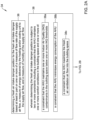
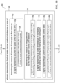
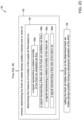
- FIGS 2A , 2B and 2C are flow diagrams that together show an illustrative method 34 for controlling a fresh air intake of an AHU (such as the AHU 10) of an HVAC system servicing a building space (such as the building space 12).
- the AHU includes a fresh air intake damper (such as the fresh air intake damper 14) for admitting a fresh air ventilation air flow, a return air duct (such as the return air duct 16) for receiving return air from the building space, a mixed air duct (such as the mixed air duct 18) for mixing the fresh air ventilation air flow from the fresh air intake damper and return air from the return air duct and providing a mixed air flow (such as the mixed air flow 22) to a heating and/or cooling unit (such as the heating and/or cooling unit 24) of the AHU which supplies a supply air flow to the building space.
- the AHU further includes a fan (such as the fan 26) for providing a motive force to move the return air, the fresh air ventilation air flow, the mixed air
- the illustrative method 34 includes determining a fresh air intake damper position for the fresh air intake damper based at least in part on one or more of a measure of flow rate of the supply air flow, a measure of energy delivered by the heating and/or cooling unit to the supply air flow, and a measure of humidity of the supply air flow, as indicated at block 36.
- determining the fresh air intake damper position is subject to two or more constraints including a constraint that the AHU maintains one or more comfort conditions in the building space, as indicated at block 38.
- the two or more constraints may further include one or more of a constraint that the AHU maintains one or more Indoor Air Quality (IAQ) contaminants in the building space below one or more IAQ thresholds, as indicted at block 38a, a constraint that the AHU minimizes energy consumption of the AHU, as indicated at block 38b, and a constraint that the AHU maximizes the fresh air ventilation air flow into the building space, as indicated at block 38c.
- IAQ Indoor Air Quality
- determining the fresh air intake damper position may include one or more processes.
- determining the fresh air intake damper position may include determining the measure of flow rate of the supply air flow, as indicated at block 42. Determining the measure of flow rate of the supply air flow may include a signal representing a current fan speed of the fan of the AHU, as indicated at block 42a. Determining the measure of flow rate of the supply air flow may include a predetermined flow rate of the fan at each of one or more predetermined fan speeds, as indicated at block 42b. The predetermined flow rate of the fan at each of one or more predetermined fan speeds may be taken from a data sheet from the manufacturer of the fan and/or AHU, or may be measured during a characterization of the fan.
- determining the fresh air intake damper position may include determining the measure of energy delivered by the heating and/or cooling unit, as indicated at block 44. Determining the measure of energy delivered by the heating and/or cooling unit may be based on a signal representing an inlet temperature of a heating and/or cooling fluid entering the heating and/or cooling unit through a control valve, as indicated at block 44a. Determining the measure of energy delivered by the heating and/or cooling unit may be based on a signal representing an outlet temperature of the heating and/or cooling fluid exiting the heating and/or cooling unit, as indicated at block 44b. In some cases, the inlet temperature and the outlet temperature may be provided by temperature sensors of the heating and/or cooling unit.
- Determining the measure of energy delivered by the heating and/or cooling unit may be based on a signal representing a current valve position of the control valve, as indicated at block 44c. Determining the measure of energy delivered by the heating and/or cooling unit may be based on a predetermined flow rate of heating and/or cooling fluid at each of one or more predetermined valve positions of the control valve, as indicated at block 44d. The predetermined flow rate of the heating and/or cooling fluid at each of one or more predetermined valve positions of the control valve may be taken from a data sheet from the manufacturer of the AHU, or may be measured during a characterization of the AHU.
- determining the fresh air intake damper position may be based on determining the measure of the humidity of the supply air flow, as indicated at block 46. In some instances, determining the measure of humidity of the supply air flow may be based on a signal representing a relative humidity of the fresh air ventilation air flow, as indicated at block 46a. In some instances, determining the measure of humidity of the supply air flow may be based on a signal representing a flow rate of the fresh air ventilation air flow, as indicated at block 46b. In some instances, determining the measure of humidity of the supply air flow may be based on a signal representing a relative humidity of the return air, as indicated at block 46c. In some instances, determining the measure of humidity of the supply air flow may be based on a signal representing a flow rate of the return air, as indicated at block 46d.
- the illustrative method 34 includes setting the fresh air intake damper to the determined fresh air intake damper position during a subsequent operation of the AHU, as indicated at block 48.
- determining the fresh air intake damper position may include determining the fresh air intake damper position based at least in part on two or more of the measure of flow rate of the supply air flow, the measure of energy delivered by the heating and/or cooling unit and the measure of humidity of the supply air flow. In some instances, determining the fresh air intake damper position may include determining the fresh air intake damper position based at least in part on the measure of flow rate of the supply air flow, the measure of energy delivered by the heating and/or cooling unit and the measure of humidity of the supply air flow. These are just examples.
- determining the fresh air intake damper position may include determining the measure of flow rate of the supply air flow based on the signal representing the current fan speed of the fan of the AHU and the predetermined flow rate of the fan at each of one or more predetermined fan speeds.
- determining the fresh air intake damper position may include determining the measure of energy delivered by the heating and/or cooling unit based on the signal representing the inlet temperature of the heating and/or cooling fluid entering the heating and/or cooling unit, the signal representing an outlet temperature of the heating and/or cooling fluid exiting the heating and/or cooling unit, the signal representing the current valve position of the control valve, and the predetermined flow rate of heating and/or cooling fluid at each of one or more predetermined valve positions of the control valve.
- determining the fresh air intake damper position may include determining the measure of humidity of the supply air flow based on the signal representing the relative humidity of the fresh air ventilation air flow, the signal representing the flow rate of the fresh air ventilation air flow, the signal representing the relative humidity of the return air, and the signal representing the flow rate of the return air.
- the measure of humidity may be determined in accordance with the equation: Mixed air rH : OA rH ⁇ OA flow rate OA flow rate + RA flow rate + RA rH ⁇ RA flow rate OA flow rate + RA flow rate , where:
- determining the fresh air intake damper position may include two or more of determining the measure of flow rate of the supply air flow, determining the measure of energy delivered by the heating and/or cooling unit and determining the measure of humidity of the supply air. In some instances, determining the fresh air intake damper position includes determining the measure of flow rate of the supply air flow based on all three of determining the measure of energy delivered by the heating and/or cooling unit, and determining the measure of humidity of the supply air flow.
- the method 50 may further include monitoring the measure of flow rate of the supply air flow for possible drift, as indicated at block 56.
- Monitoring the measure of flow rate of the supply air flow for possible drift may include comparing a current measure of flow rate of the supply air flow with an average of two or more previous measures of flow rate of the supply air flow, as indicated at block 56a.
- Monitoring the measure of flow rate of the supply air flow for possible drift may include comparing a current measure of flow rate of the supply air flow with a predetermined flow rate threshold, as indicated at block 56b.
- Monitoring the measure of flow rate of the supply air flow for possible drift may include comparing one or more changes in the measure of flow rate of the supply air flow with one or more changes in a pressure (e.g. duct pressure) in the supply air flow, as indicated at block 56c.
- a pressure e.g. duct pressure
- the illustrative method 50 may further include monitoring the measure of energy delivered by the heating and/or cooling unit to the supply air flow for possible drift, as indicated at block 58.
- Monitoring the measure of energy delivered by the heating and/or cooling unit to the supply air flow for possible drift may include comparing a current measure of energy delivered by the heating and/or cooling unit to the supply air flow with a predetermined an energy delivery baseline, as indicated at block 58a.
- an energy baseline for the AHU may be established using features such as outside temp, cooling degree days, heating degree days, occupancy and humidity. This can be used to compute expected energy consumption. If for a long duration, the calculated energy is higher than the observed energy, such as more than 2 standard deviations from baseline, for a long duration (such as a week), then drift is indicated (assuming flow and pressure hasn't changed drastically)
- Monitoring the measure of energy delivered by the heating and/or cooling unit to the supply air flow for possible drift may include comparing a temperature difference between an inlet temperature and an outlet temperature of a heating and/or cooling fluid flowing through the heating and/or cooling unit through a control valve with a predetermined expected temperature difference under similar conditions (e.g. similar mixed air temperature and flow), as indicated at block 58c.
- the predetermined expected temperature difference versus flow rate of the heating and/or cooling fluid over certain conditions may be derived from a data sheet of the manufacturer of the AHU, or may be measured during a characterization of the AHU.
Landscapes
- Engineering & Computer Science (AREA)
- Chemical & Material Sciences (AREA)
- Combustion & Propulsion (AREA)
- Mechanical Engineering (AREA)
- General Engineering & Computer Science (AREA)
- Physics & Mathematics (AREA)
- Signal Processing (AREA)
- Fluid Mechanics (AREA)
- Fuzzy Systems (AREA)
- Mathematical Physics (AREA)
- Air Conditioning Control Device (AREA)
Abstract
Controlling a fresh air intake includes determining a fresh air intake damper position based on the supply air flowrate, a measure of energy delivered to the supply air flow, or a measure of humidity of the supply air flow. Determining the fresh air intake damper position is subject to a constraint that the AHU maintains one or more comfort conditions in the building space and one or more of a constraint regarding maintaining one or more Indoor Air Quality (IAQ) contaminants in the building space below one or more IAQ thresholds, minimizing energy consumption of the AHU, and maximizing the fresh air ventilation air flow into the building space. Various parameters used to determine the fresh air intake damper position may be derived from available sensed conditions so as to reduce the number of physical sensors that are required.
Description
- The present disclosure relates to methods and systems for operating a Heating, Ventilating and Air Conditioning (HVAC) system.
- HVAC systems provide conditioned air for heating and cooling the interior of a building. Some HVAC systems also can provide fresh air ventilation into the building while exhausting an equivalent amount of inside air. Such fresh air ventilation is useful in reducing contaminates produced in the building. However, there are often costs involved in conditioning the fresh air before it can be deployed in the building. For example, in the winter, the cold fresh air must typically be heated by the HVAC system, and in some cases, humidity must be added. Likewise, in the summer, the warm fresh air must typically be cooled by the HVAC system, and in some cases, humidity must be removed. Thus, to reduce operating costs, it is often desirable to minimize the ventilation rate while still adequately ventilating the building given the current contaminates or expected contaminates in the building.
- Under some conditions, such as during a pandemic, it may be desirable to prioritize an increased ventilation rate over energy costs to help reduce the spread of pathogens within the building. Under these conditions, if the ventilation rate is set too high, given the current indoor and outdoor conditions, the HVAC system may lack the heating and/or cooling capacity to adequately condition the incoming fresh air while still maintaining occupant comfort in the building. What would be desirable are methods and systems for operating an HVAC system to provide adequate ventilation while minimizing energy usage and maintaining comfort.
- The present disclosure relates to methods and systems for operating a Heating, Ventilating and Air Conditioning (HVAC) system. An example may be found in a method for controlling a fresh air intake of an Air Handling Unit (AHU) of an HVAC (Heating, Ventilating and Air Conditioning) system servicing a building space. In this example, the AHU includes a fresh air intake damper for admitting a fresh air ventilation air flow, a return air duct for receiving return air from the building space, a mixed air duct for mixing the fresh air ventilation air flow from the fresh air intake damper and return air from the return air duct and providing a mixed air flow to a heating and/or cooling unit of the AHU which supplies a supply air flow to the building space. The AHU further includes a fan for providing a motive force to move the return air, the fresh air ventilation air flow, the mixed air flow and the supply air flow through the AHU. The illustrative method includes determining a fresh air intake damper position for the fresh air intake damper based at least in part on one or more of a measure of flow rate of the supply air flow, a measure of energy delivered by the heating and/or cooling unit to the supply air flow, and a measure of humidity of the supply air flow. Determining the fresh air intake damper position is subject to two or more constraints including a constraint that the AHU maintains one or more comfort conditions in the building space and one or more of a constraint that the AHU maintains one or more Indoor Air Quality (IAQ) contaminants in the building space below one or more IAQ thresholds, a constraint that the AHU minimizes energy consumption of the AHU, and a constraint that the AHU maximizes the fresh air ventilation air flow into the building space.
- In some instances, determining the fresh air intake damper position includes one or more of determining the measure of flow rate of the supply air flow based on a signal representing a current fan speed of the fan of the AHU and a predetermined flow rate of the fan at each of one or more predetermined fan speeds; determining the measure of energy delivered by the heating and/or cooling unit based on a signal representing an inlet temperature of a heating and/or cooling fluid entering the heating and/or cooling unit through a control valve, a signal representing an outlet temperature of the heating and/or cooling fluid exiting the heating and/or cooling unit, a signal representing a current valve position of the control valve and a predetermined flow rate of heating and/or cooling fluid at each of one or more predetermined valve positions of the control valve; and determining the measure of humidity of the supply air flow based on a signal representing a relative humidity of the fresh air ventilation air flow, a signal representing a flow rate of the fresh air ventilation air flow, a signal representing a relative humidity of the return air, and a signal representing a flow rate of the return air. The method includes setting the fresh air intake damper to the determined fresh air intake damper position during a subsequent operation of the AHU.
- Another example may be found in an Air Handling Unit (AHU) of an HVAC (Heating, Ventilating and Air Conditioning) system for servicing a building space. In this example, the AHU includes a fresh air intake damper for admitting a fresh air ventilation air flow, a return air duct for receiving return air from the building space, a heating and/or cooling unit, a mixed air duct for mixing the fresh air ventilation air flow from the fresh air intake damper and return air from the return air duct and providing a mixed air flow to the heating and/or cooling unit of the AHU which supplies a supply air flow to the building space, a fan for providing a motive force to move the return air, the fresh air ventilation air flow, the mixed air flow and the supply air flow through the AHU, and a controller operatively coupled to the fresh air intake damper, the heating and/or cooling unit and the fan. The controller is configured to determine a fresh air intake damper position for the fresh air intake damper based at least in part on one or more of a measure of flow rate of the supply air flow, a measure of energy delivered by the heating and/or cooling unit to the supply air flow, and a measure of humidity of the supply air flow. The fresh air intake damper position is subject to two or more constraints including a constraint that the AHU maintains one or more comfort conditions in the building space and one or more of a constraint that the AHU maintains one or more Indoor Air Quality (IAQ) contaminants in the building space below one or more IAQ thresholds, a constraint that the AHU minimizes energy consumption of the AHU, and a constraint that the AHU maximizes the fresh air ventilation air flow into the building space. The controller when determining the fresh air intake damper position is configured to include one or more of determining the measure of flow rate of the supply air flow based on a signal representing a current fan speed of the fan of the AHU and a predetermined flow rate of the fan at each of one or more predetermined fan speeds; determining the measure of energy delivered by the heating and/or cooling unit based on a signal representing an inlet temperature of a heating and/or cooling fluid entering the heating and/or cooling unit through a control valve, a signal representing an outlet temperature of the heating and/or cooling fluid exiting the heating and/or cooling unit, a signal representing a current valve position of the control valve and a predetermined flow rate of heating and/or cooling fluid at each of one or more predetermined valve positions of the control valve; and determining the measure of humidity of the supply air flow based on a signal representing a relative humidity of the fresh air ventilation air flow, a signal representing a flow rate of the fresh air ventilation air flow, a signal representing a relative humidity of the return air, and a signal representing a flow rate of the return air. The controller is configured to set the fresh air intake damper to the determined fresh air intake damper position.
- Another example may be found in a non-transitory computer readable medium storing instructions thereon that when executed by one or more processors cause the one or more processors to control a fresh air intake damper of an Air Handling Unit (AHU) of an HVAC (Heating, Ventilating and Air Conditioning) system servicing a building space. In this example, the AHU includes a fresh air intake damper for admitting a fresh air ventilation air flow, a return air duct for receiving return air from the building space, a heating and/or cooling unit, a mixed air duct for mixing the fresh air ventilation air flow from the fresh air intake damper and return air from the return air duct and providing a mixed air flow to the heating and/or cooling unit of the AHU which supplies a supply air flow to the building space and a fan for providing a motive force to move the return air, the fresh air ventilation air flow, the mixed air flow and the supply air flow through the AHU. The instructions cause the one or more processors to determine a fresh air intake damper position for the fresh air intake damper based at least in part on one or more of a measure of flow rate of the supply air flow, a measure of energy delivered by the heating and/or cooling unit to the supply air flow, and a measure of humidity of the supply air flow. The fresh air intake damper position is subject to two or more constraints including a constraint that the AHU maintains one or more comfort conditions in the building space and one or more of a constraint that the AHU maintains one or more Indoor Air Quality (IAQ) contaminants in the building space below one or more IAQ thresholds, a constraint that the AHU minimizes energy consumption of the AHU, and a constraint that the AHU maximizes the fresh air ventilation air flow into the building space. When determining the fresh air intake damper position, the instructions cause the one or more processor to perform one or more of determining the measure of flow rate of the supply air flow based on a signal representing a current fan speed of the fan of the AHU and a predetermined flow rate of the fan at each of one or more predetermined fan speeds; determining the measure of energy delivered by the heating and/or cooling unit based on a signal representing an inlet temperature of a heating and/or cooling fluid entering the heating and/or cooling unit through a control valve, a signal representing an outlet temperature of the heating and/or cooling fluid exiting the heating and/or cooling unit, a signal representing a current valve position of the control valve, and a predetermined flow rate of heating and/or cooling fluid at each of one or more predetermined valve positions of the control valve; determining the measure of humidity of the supply air flow based on a signal representing a relative humidity of the fresh air ventilation air flow, a signal representing a flow rate of the fresh air ventilation air flow, a signal representing a relative humidity of the return air, and a signal representing a flow rate of the return air. The one or more processors are caused to set the fresh air intake damper to the determined fresh air intake damper position.
- The preceding summary is provided to facilitate an understanding of some of the innovative features unique to the present disclosure and is not intended to be a full description. A full appreciation of the disclosure can be gained by taking the entire specification, claims, figures, and abstract as a whole.
- The disclosure may be more completely understood in consideration of the following description of various examples in connection with the accompanying drawings, in which:
-
Figure 1 is a schematic block diagram showing an illustrative Air Handling Unit (AHU) that forms part of a Heating, Ventilating and Air Conditioning (HVAC) system servicing a building space; -
Figures 2A ,2B and2C are flow diagrams that together show an illustrative method for controlling a fresh air intake of an AHU such as the AHU shown inFigure 1 ; -
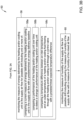
Figures 3A and3B are flow diagrams that together show an illustrative method for controlling a fresh air intake of an AHU such as the AHU shown inFigure 1 ; -
Figure 4 is a graph providing comparisons between estimated and actual flow rates through an AHU such as the AHU ofFigure 1 ; and -
Figure 5 is a graph providing comparisons between estimated and actual supply air humidity. - While the disclosure is amenable to various modifications and alternative forms, specifics thereof have been shown by way of example in the drawings and will be described in detail. It should be understood, however, that the intention is not to limit the disclosure to the particular examples described. On the contrary, the intention is to cover all modifications, equivalents, and alternatives falling within the spirit and scope of the disclosure.
- The following description should be read with reference to the drawings, in which like elements in different drawings are numbered in like fashion. The drawings, which are not necessarily to scale, depict examples that are not intended to limit the scope of the disclosure. Although examples are illustrated for the various elements, those skilled in the art will recognize that many of the examples provided have suitable alternatives that may be utilized.
- All numbers are herein assumed to be modified by the term "about", unless the content clearly dictates otherwise. The recitation of numerical ranges by endpoints includes all numbers subsumed within that range (e.g., 1 to 5 includes 1, 1.5, 2, 2.75, 3, 3.80, 4, and 5).
- As used in this specification and the appended claims, the singular forms "a", "an", and "the" include the plural referents unless the content clearly dictates otherwise. As used in this specification and the appended claims, the term "or" is generally employed in its sense including "and/or" unless the content clearly dictates otherwise.
- It is noted that references in the specification to "an embodiment", "some embodiments", "other embodiments", etc., indicate that the embodiment described may include a particular feature, structure, or characteristic, but every embodiment may not necessarily include the particular feature, structure, or characteristic. Moreover, such phrases are not necessarily referring to the same embodiment. Further, when a particular feature, structure, or characteristic is described in connection with an embodiment, it is contemplated that the feature, structure, or characteristic is described in connection with an embodiment, it is contemplated that the feature, structure, or characteristic may be applied to other embodiments whether or not explicitly described unless clearly stated to the contrary.
-
Figure 1 is a schematic block diagram showing an illustrative Air Handling Unit (AHU) 10 that may form part of a Heating, Ventilating and Air Conditioning (HVAC) system servicing abuilding space 12. Thebuilding space 12 may represent an entire building, for example, or a single floor or zone within a building. The AHU 10 includes a freshair intake damper 14 for admitting a fresh air ventilation flow from outside of the building. The AHU 10 includes areturn air duct 16 for receiving return air from thebuilding space 12. The AHU 10 includes amixed air duct 18 for mixing a fresh airventilation air flow 20 from the freshair intake damper 14 and return air from thereturn air duct 16 and provides amixed air flow 22. Themixed air flow 22 flows to a heating and/orcooling unit 24. In some instances, as shown, afan 26 may be disposed between themixed air duct 18 and the heating and/orcooling unit 24. In some instances, the heating and/orcooling unit 24 may be disposed between themixed air duct 18 and thefan 26. In either case, thefan 26 provides a motive force to move the return air within thereturn air duct 16 and the fresh airventilation air flow 20. In some instances, thefan 26 also provides a motive force to move thesupply air flow 28. The heated or cooled air exiting the heating and/orcooling unit 24 represents asupply air flow 28. In some instances, theAHU 10 may include onefan 26, or may include two ormore fans 26. TheAHU 10 includes acontrol valve 30 that is configured to control the flow of a heating or cooling fluid into the heating and/orcooling unit 24, including an inlet flow 30a and anoutlet flow 30b. - A
controller 32 is operatively coupled to the freshair intake damper 14, the heating and/orcooling unit 24 and thefan 26. Thecontroller 32 is configured to determine a fresh air intake damper position for the freshair intake damper 14 based at least in part on one or more of a measure of flow rate of thesupply air flow 28, a measure of energy delivered by the heating and/or cooling unit to thesupply air flow 28, and a measure of humidity of thesupply air flow 28. - In some instances, the fresh air intake damper position is subject to two or more constraints including a constraint that the
AHU 10 maintains one or more comfort conditions (e.g. temperature) in thebuilding space 12 and one or more of a constraint that the AHU10 maintains one or more Indoor Air Quality (IAQ) contaminants (e.g. CO2, PM2.5 and/or TVOC) in thebuilding space 12 below one or more IAQ thresholds, a constraint that theAHU 10 minimizes energy consumption of theAHU 10, and a constraint that theAHU 10 maximizes the fresh airventilation air flow 20 into thebuilding space 12. - In some instances, the
controller 32, when determining the fresh air intake damper position, may be configured to determine the measure of flow rate of thesupply air flow 28 based on a signal representing a current fan speed of thefan 26 of theAHU 10 and a predetermined flow rate of thefan 26 at each of one or more predetermined fan speeds. The predetermined flow rate of thefan 26 at each of one or more predetermined fan speeds may be taken from a data sheet from the manufacturer of thefan 26, or may be measured during a characterization of thefan 26. - The
controller 32 may be configured to determine the measure of energy delivered by the heating and/orcooling unit 24 based on a signal representing an inlet temperature of a heating and/or cooling fluid entering the heating and/orcooling unit 24 through a control valve, a signal representing an outlet temperature of the heating and/or cooling fluid exiting the heating and/orcooling unit 24, a signal representing a current valve position of thecontrol valve 30, and a predetermined flow rate of heating and/or cooling fluid at each of one or more predetermined valve positions of thecontrol valve 30. In some cases, the heating and/orcooling unit 24 may include temperature sensors that measure the inlet temperature of the heating and/or cooling fluid entering the heating and/orcooling unit 24 through the control valve and the outlet temperature of the heating and/or cooling fluid exiting the heating and/orcooling unit 24. The predetermined flow rate of the heating and/or cooling fluid at each of one or more predetermined valve positions of thecontrol valve 30 may be taken from a data sheet from the manufacturer of theAHU 10, or may be measured during a characterization of theAHU 10. - In some instances, the
controller 32 may be configured to determine the measure of humidity of thesupply air flow 28 based on a signal representing a relative humidity of the fresh airventilation air flow 20, a signal representing a flow rate of the fresh airventilation air flow 20, a signal representing a relative humidity of the return air flowing through thereturn air duct 16, and a signal representing a flow rate of the return air flowing through thereturn air duct 16. The controller is configured to set the freshair intake damper 14 to the determined fresh air intake damper position during a subsequent operation of theAHU 10. - In some instances, the
controller 32 may be configured to determine the measure of flow rate of thesupply air flow 28 based on the signal representing the current fan speed of thefan 26 of theAHU 10 and the predetermined flow rate of thefan 26 at each of one or more predetermined fan speeds. In some instances, the measure of flow rate of thesupply air flow 28 may be determined in accordance with the equation:
- CFM represents the flow rate of the
supply air flow 28 in Cubic Feet per Minute (CFM); - RPM represents the current fan speed of the
fan 26 of theAHU 10 in Revolutions Per Minute (RPM); - design RPM represents one of the one or more predetermined fan speeds of the fan 26 (e.g. from a data sheet of the fan 26); and
- design CFM represents the predetermined flow rate at the one of the one or more predetermined fan speeds of the fan 26 (design RPM) (e.g. from the data sheet of the fan 26).
- In some instances, the
controller 32 may be configured to determine the measure of energy delivered by the heating and/orcooling unit 24 based on the signal representing the inlet temperature of the heating and/or cooling fluid entering the heating and/orcooling unit 24, the signal representing an outlet temperature of the heating and/or cooling fluid exiting the heating and/orcooling unit 24, the signal representing the current valve position of thecontrol valve 30 and the predetermined flow rate of heating and/or cooling fluid at each of one or more predetermined valve positions of thecontrol valve 30. In some instances, the measure of energy is determined in accordance with the equation:
- Q represents the measure of energy delivered by the heating and/or
cooling unit 24; - m represents the mass flow rate of the heating and/or cooling fluid flowing through the heating and/or
cooling unit 24; - c represents the specific heat capacity of the heating and/or cooling fluid; and
- ΔT represents a temperature difference between the inlet temperature and the outlet temperature of the heating and/or cooling fluid.
- In some instances, the
controller 32 may be configured to determine the measure of humidity of the supply air flow based on the signal representing the relative humidity of the fresh airventilation air flow 20, the signal representing the flow rate of the fresh airventilation air flow 20, the signal representing the relative humidity of thereturn air 16, and the signal representing the flow rate of the return air. In some instances, the measure of humidity may be determined in accordance with the equation:
- Mixed air rH represents a measure of relative humidity of the
mixed air flow 22; - OA rH represents the relative humidity of the fresh air
ventilation air flow 20, sometimes measured by a fresh air or outside air humidity sensor; - OA flow rate represents the flow rate of the fresh air
ventilation air flow 20; - RA rH represents the relative humidity of the
return air 16 flowing within thereturn air duct 16, sometimes measured by a return air humidity sensor or a humidity sensor in thebuilding space 12; and - RA flow rate represents the flow rate of the return air flowing within the
return air duct 16. - In some instances, the
controller 32 may be configured to monitor the measure of flow rate of thesupply air flow 28 for possible drift over time by performing one or more of comparing a current measure of flow rate of thesupply air flow 28 with an average of two or more previous measures of flow rate of thesupply air flow 28, comparing a current measure of flow rate of thesupply air flow 28 with a predetermined flow rate threshold, and comparing one or more changes in the measure of flow rate of thesupply air flow 28 with one or more changes in a pressure in thesupply air flow 28. In some instances, thecontroller 32 may be configured to monitor the measure of humidity of thesupply air flow 28 for possible drift over time by, for example, comparing the measure of humidity of thesupply air flow 28 with a measure of humidity of themixed air flow 22. - In some instances, the
controller 32 may be configured to monitor the measure of energy delivered by the heating and/orcooling unit 24 to thesupply air flow 28 for possible drift over time by performing one or more of comparing a current measure of energy delivered by the heating and/orcooling unit 24 to thesupply air flow 28 with a predetermined energy delivery baseline, comparing a performance of the heating and/orcooling unit 24 over time to detect a change in performance of the heating and/orcooling unit 24 over time, and comparing a temperature difference between an inlet temperature (of the inlet flow 30a) and an outlet temperature (of theoutlet flow 30b) of the heating and/or cooling fluid flowing through the heating and/orcooling unit 24 with a predetermined expected temperature difference. When a drift is detected in any of the measure of flow rate of thesupply air flow 28, the measure of humidity of thesupply air flow 28, or the measure of energy delivered by the heating and/orcooling unit 24, an alarm is issued indicating that the AHU should be re-calibrated and/or serviced. -
Figures 2A ,2B and2C are flow diagrams that together show anillustrative method 34 for controlling a fresh air intake of an AHU (such as the AHU 10) of an HVAC system servicing a building space (such as the building space 12). The AHU includes a fresh air intake damper (such as the fresh air intake damper 14) for admitting a fresh air ventilation air flow, a return air duct (such as the return air duct 16) for receiving return air from the building space, a mixed air duct (such as the mixed air duct 18) for mixing the fresh air ventilation air flow from the fresh air intake damper and return air from the return air duct and providing a mixed air flow (such as the mixed air flow 22) to a heating and/or cooling unit (such as the heating and/or cooling unit 24) of the AHU which supplies a supply air flow to the building space. The AHU further includes a fan (such as the fan 26) for providing a motive force to move the return air, the fresh air ventilation air flow, the mixed air flow and the supply air flow through the AHU. - The
illustrative method 34 includes determining a fresh air intake damper position for the fresh air intake damper based at least in part on one or more of a measure of flow rate of the supply air flow, a measure of energy delivered by the heating and/or cooling unit to the supply air flow, and a measure of humidity of the supply air flow, as indicated atblock 36. - In some instances, determining the fresh air intake damper position is subject to two or more constraints including a constraint that the AHU maintains one or more comfort conditions in the building space, as indicated at
block 38. The two or more constraints may further include one or more of a constraint that the AHU maintains one or more Indoor Air Quality (IAQ) contaminants in the building space below one or more IAQ thresholds, as indicted atblock 38a, a constraint that the AHU minimizes energy consumption of the AHU, as indicated atblock 38b, and a constraint that the AHU maximizes the fresh air ventilation air flow into the building space, as indicated atblock 38c. - In some instances, and referring now to
Figure 2B , and as indicated atblock 40, determining the fresh air intake damper position may include one or more processes. In some instances, determining the fresh air intake damper position may include determining the measure of flow rate of the supply air flow, as indicated atblock 42. Determining the measure of flow rate of the supply air flow may include a signal representing a current fan speed of the fan of the AHU, as indicated atblock 42a. Determining the measure of flow rate of the supply air flow may include a predetermined flow rate of the fan at each of one or more predetermined fan speeds, as indicated atblock 42b. The predetermined flow rate of the fan at each of one or more predetermined fan speeds may be taken from a data sheet from the manufacturer of the fan and/or AHU, or may be measured during a characterization of the fan. - In some instances, determining the fresh air intake damper position may include determining the measure of energy delivered by the heating and/or cooling unit, as indicated at
block 44. Determining the measure of energy delivered by the heating and/or cooling unit may be based on a signal representing an inlet temperature of a heating and/or cooling fluid entering the heating and/or cooling unit through a control valve, as indicated at block 44a. Determining the measure of energy delivered by the heating and/or cooling unit may be based on a signal representing an outlet temperature of the heating and/or cooling fluid exiting the heating and/or cooling unit, as indicated atblock 44b. In some cases, the inlet temperature and the outlet temperature may be provided by temperature sensors of the heating and/or cooling unit. Determining the measure of energy delivered by the heating and/or cooling unit may be based on a signal representing a current valve position of the control valve, as indicated atblock 44c. Determining the measure of energy delivered by the heating and/or cooling unit may be based on a predetermined flow rate of heating and/or cooling fluid at each of one or more predetermined valve positions of the control valve, as indicated at block 44d. The predetermined flow rate of the heating and/or cooling fluid at each of one or more predetermined valve positions of the control valve may be taken from a data sheet from the manufacturer of the AHU, or may be measured during a characterization of the AHU. - Continuing on
Figure 2C , determining the fresh air intake damper position may be based on determining the measure of the humidity of the supply air flow, as indicated atblock 46. In some instances, determining the measure of humidity of the supply air flow may be based on a signal representing a relative humidity of the fresh air ventilation air flow, as indicated atblock 46a. In some instances, determining the measure of humidity of the supply air flow may be based on a signal representing a flow rate of the fresh air ventilation air flow, as indicated atblock 46b. In some instances, determining the measure of humidity of the supply air flow may be based on a signal representing a relative humidity of the return air, as indicated atblock 46c. In some instances, determining the measure of humidity of the supply air flow may be based on a signal representing a flow rate of the return air, as indicated atblock 46d. - The
illustrative method 34 includes setting the fresh air intake damper to the determined fresh air intake damper position during a subsequent operation of the AHU, as indicated atblock 48. - In some instances, determining the fresh air intake damper position may include determining the fresh air intake damper position based at least in part on two or more of the measure of flow rate of the supply air flow, the measure of energy delivered by the heating and/or cooling unit and the measure of humidity of the supply air flow. In some instances, determining the fresh air intake damper position may include determining the fresh air intake damper position based at least in part on the measure of flow rate of the supply air flow, the measure of energy delivered by the heating and/or cooling unit and the measure of humidity of the supply air flow. These are just examples.
- In some instances, determining the fresh air intake damper position may include determining the measure of flow rate of the supply air flow based on the signal representing the current fan speed of the fan of the AHU and the predetermined flow rate of the fan at each of one or more predetermined fan speeds. As an example, the measure of flow rate of the supply air flow may be determined in accordance with the equation:

- CFM represents the flow rate of the supply air flow in Cubic Feet per Minute (CFM);
- RPM represents the current fan speed of the fan of the AHU in Revolutions Per Minute (RPM);
- design RPM represents one of the one or more the predetermined fan speeds of the fan (e.g. from a data sheet of the fan); and
- design CFM represents the predetermined flow rate at the one of the one or more predetermined fan speeds of the fan (design RPM) (e.g. from the data sheet of the fan).
- In some instances, determining the fresh air intake damper position may include determining the measure of energy delivered by the heating and/or cooling unit based on the signal representing the inlet temperature of the heating and/or cooling fluid entering the heating and/or cooling unit, the signal representing an outlet temperature of the heating and/or cooling fluid exiting the heating and/or cooling unit, the signal representing the current valve position of the control valve, and the predetermined flow rate of heating and/or cooling fluid at each of one or more predetermined valve positions of the control valve. As an example, the measure of energy may be determined in accordance with the equation:

- Q represents the measure of energy delivered by the heating and/or cooling unit;
- m represents the mass flow rate of the heating and/or cooling fluid flowing through the heating and/or cooling unit;
- c represents the specific heat capacity of the heating and/or cooling fluid; and
- ΔT represents a temperature difference between the inlet temperature and the outlet temperature of the heating and/or cooling fluid.
- In some instances, determining the fresh air intake damper position may include determining the measure of humidity of the supply air flow based on the signal representing the relative humidity of the fresh air ventilation air flow, the signal representing the flow rate of the fresh air ventilation air flow, the signal representing the relative humidity of the return air, and the signal representing the flow rate of the return air. As an example, the measure of humidity may be determined in accordance with the equation:

- Mixed air rH represents a measure of relative humidity of the mixed air flow;
- OA rH represents the relative humidity of the fresh air ventilation air flow;
- OA flow rate represents the flow rate of the fresh air ventilation air flow;
- RA rH represents the relative humidity of the return air;
- RA flow rate represents the flow rate of the return air; and
- In some instances, determining the fresh air intake damper position may include two or more of determining the measure of flow rate of the supply air flow, determining the measure of energy delivered by the heating and/or cooling unit and determining the measure of humidity of the supply air. In some instances, determining the fresh air intake damper position includes determining the measure of flow rate of the supply air flow based on all three of determining the measure of energy delivered by the heating and/or cooling unit, and determining the measure of humidity of the supply air flow.
-
Figures 3A and3B are flow diagrams that together show anillustrative method 50 for controlling a fresh air intake of an AHU (such as the AHU 10) of an HVAC system servicing a building space (such as the building space 12). The AHU including a fresh air intake damper (such as the fresh air intake damper 14) for admitting a fresh air ventilation air flow, a return air duct (such as the return air duct 16) for receiving return air from the building space, a mixed air duct (such as the mixed air duct 18) for mixing the fresh air ventilation air flow from the fresh air intake damper and return air from the return air duct and providing a mixed air flow (such as the mixed air flow 22) to a heating and/or cooling unit (such as the heating and/or cooling unit 24) of the AHU which supplies a supply air flow to the building space, the AHU including a fan (such as the fan 26) for providing a motive force to move the return air, the fresh air ventilation air flow, the mixed air flow and the supply air flow through the AHU. - The
illustrative method 50 includes determining a fresh air intake damper position for the fresh air intake damper based at least in part on one or more of a measure of flow rate of the supply air flow, a measure of energy delivered by the heating and/or cooling unit to the supply air flow, and a measure of humidity of the supply air flow, as indicated atblock 52. Theillustrative method 50 includes setting the fresh air intake damper to the determined fresh air intake damper position during a subsequent operation of the AHU, as indicated atblock 54. - In some instances, the
method 50 may further include monitoring the measure of flow rate of the supply air flow for possible drift, as indicated atblock 56. Monitoring the measure of flow rate of the supply air flow for possible drift may include comparing a current measure of flow rate of the supply air flow with an average of two or more previous measures of flow rate of the supply air flow, as indicated atblock 56a. Monitoring the measure of flow rate of the supply air flow for possible drift may include comparing a current measure of flow rate of the supply air flow with a predetermined flow rate threshold, as indicated atblock 56b. Monitoring the measure of flow rate of the supply air flow for possible drift may include comparing one or more changes in the measure of flow rate of the supply air flow with one or more changes in a pressure (e.g. duct pressure) in the supply air flow, as indicated atblock 56c. - Continuing on
Figure 3B , theillustrative method 50 may further include monitoring the measure of energy delivered by the heating and/or cooling unit to the supply air flow for possible drift, as indicated atblock 58. Monitoring the measure of energy delivered by the heating and/or cooling unit to the supply air flow for possible drift may include comparing a current measure of energy delivered by the heating and/or cooling unit to the supply air flow with a predetermined an energy delivery baseline, as indicated atblock 58a. For example, an energy baseline for the AHU may be established using features such as outside temp, cooling degree days, heating degree days, occupancy and humidity. This can be used to compute expected energy consumption. If for a long duration, the calculated energy is higher than the observed energy, such as more than 2 standard deviations from baseline, for a long duration (such as a week), then drift is indicated (assuming flow and pressure hasn't changed drastically) - Monitoring the measure of energy delivered by the heating and/or cooling unit to the supply air flow for possible drift may include comparing a performance of the heating and/or cooling unit over time to detect a change in performance of the heating and/or cooling unit, as indicated at
block 58b. For example, if the heating and/or cooling flow changes over time to achieve the same or similar temperature drops across the inlet and outlet of the heating and/or cooling unit under similar conditions (e.g. similar mixed air temperature), a drift is indicated in the performance of the heating and/or cooling unit. - Monitoring the measure of energy delivered by the heating and/or cooling unit to the supply air flow for possible drift may include comparing a temperature difference between an inlet temperature and an outlet temperature of a heating and/or cooling fluid flowing through the heating and/or cooling unit through a control valve with a predetermined expected temperature difference under similar conditions (e.g. similar mixed air temperature and flow), as indicated at
block 58c. The predetermined expected temperature difference versus flow rate of the heating and/or cooling fluid over certain conditions (e.g. mixed air temperature and flow) may be derived from a data sheet of the manufacturer of the AHU, or may be measured during a characterization of the AHU. In some instances, themethod 50 may further include monitoring the measure of humidity of the supply air flow for possible drift includes, for example, comparing the measure of humidity of the supply air flow with a measure of humidity of the mixed air flow, as indicated atblock 60. If these values start to diverge over time, drift may be indicated in the measure of humidity of the supply air flow. -
Figure 4 is a graph providing comparisons between estimated and actual flow rates of supply air.Figure 4 includes afirst graph 62 including adata line 64 that shows fan speed over time. As can be seen, the fan speed was fairly constant from 7 am to about 12 noon for the day shown, and varied considerably during the afternoon for the day shown.Figure 4 includes asecond graph 66 including adata line 68 showing actual flow rate and adata line 70 showing estimated flow rate. It will be appreciated that the estimatedflow rate 70 is not very close to theactual flow rate 78, without any correction factor.Figure 4 includes athird graph 72 including adata line 74 showing actual flow rate and adata line 76 showing the estimated flow rate with a correction factor. It will be appreciated that in the morning of the day shown, the estimatedflow rate 76 is quite close to theactual flow rate 74. This demonstrates that flow rate can be reasonably estimated in the absence of an air flow sensor (e.g. based on fan speed). Significant changes in the afternoon fan speed seem to have impacted accuracy in the afternoon. -
Figure 5 is a graph providing comparisons between estimated and actual supply air humidity.Figure 5 includes agraph 78 including afirst data line 80 showing actual supply air relative humidity and asecond data line 82 showing estimated supply air relative humidity. While the actual supply air relative humidity varied more than the estimated supply air relative humidity, it will be appreciated that the estimated supply air relative humidity is reasonably close to an average of the actual supply air relative humidity. This demonstrates that supply air humidity can be reasonably estimated in the absence of a supply air relative humidity sensor. - Having thus described several illustrative embodiments of the present disclosure, those of skill in the art will readily appreciate that yet other embodiments may be made and used within the scope of the claims hereto attached. It will be understood, however, that this disclosure is, in many respects, only illustrative. Changes may be made in details, particularly in matters of shape, size, arrangement of parts, and exclusion and order of steps, without exceeding the scope of the disclosure. The disclosure's scope is, of course, defined in the language in which the appended claims are expressed.


Claims (15)
- A method for controlling a fresh air intake of an Air Handling Unit (AHU) of an HVAC (Heating, Ventilating and Air Conditioning) system servicing a building space, the AHU including a fresh air intake damper for admitting a fresh air ventilation air flow, a return air duct for receiving return air from the building space, a mixed air duct for mixing the fresh air ventilation air flow from the fresh air intake damper and return air from the return air duct and providing a mixed air flow to a heating and/or cooling unit of the AHU which supplies a supply air flow to the building space, the AHU including a fan for providing a motive force to move the return air, the fresh air ventilation air flow, the mixed air flow and the supply air flow through the AHU, the method comprising:determining a fresh air intake damper position for the fresh air intake damper based at least in part on one or more of a measure of flow rate of the supply air flow, a measure of energy delivered by the heating and/or cooling unit to the supply air flow, and a measure of humidity of the supply air flow;wherein determining the fresh air intake damper position is subject to two or more constraints including a constraint that the AHU maintains one or more comfort conditions in the building space and one or more of:a constraint that the AHU maintains one or more Indoor Air Quality (IAQ) contaminants in the building space below one or more IAQ thresholds;a constraint that the AHU minimizes energy consumption of the AHU; anda constraint that the AHU maximizes the fresh air ventilation air flow into the building space;wherein determining the fresh air intake damper position includes one or more of:determining the measure of flow rate of the supply air flow based on:a signal representing a current fan speed of the fan of the AHU; anda predetermined flow rate of the fan at each of one or more predetermined fan speeds;determining the measure of energy delivered by the heating and/or cooling unit based on:a signal representing an inlet temperature of a heating and/or cooling fluid entering the heating and/or cooling unit through a control valve;a signal representing an outlet temperature of the heating and/or cooling fluid exiting the heating and/or cooling unit;a signal representing a current valve position of the control valve; anda predetermined flow rate of heating and/or cooling fluid at each of one or more predetermined valve positions of the control valve;determining the measure of humidity of the supply air flow based on:a signal representing a relative humidity of the fresh air ventilation air flow;a signal representing a flow rate of the fresh air ventilation air flow;a signal representing a relative humidity of the return air; anda signal representing a flow rate of the return air;setting the fresh air intake damper to the determined fresh air intake damper position during a subsequent operation of the AHU.
- The method of claim 1, wherein determining the fresh air intake damper position includes determining the fresh air intake damper position based at least in part on two or more of the measure of flow rate of the supply air flow, the measure of energy delivered by the heating and/or cooling unit and the measure of humidity of the supply air flow.
- The method of claim 1, wherein determining the fresh air intake damper position includes determining the fresh air intake damper position based at least in part on the measure of flow rate of the supply air flow, the measure of energy delivered by the heating and/or cooling unit and the measure of humidity of the supply air flow.
- The method of claim 1, wherein determining the fresh air intake damper position includes:
determining the measure of flow rate of the supply air flow based on:the signal representing the current fan speed of the fan of the AHU; andthe predetermined flow rate of the fan at each of one or more predetermined fan speeds. - The method of claim 4, wherein the measure of flow rate of the supply air flow is determined in accordance with the equation:
 CFM represents the flow rate of the supply air flow in Cubic Feet per Minute (CFM);RPM represents the current fan speed of the fan of the AHU in Revolutions Per Minute (RPM);design RPM represents one of the one or more the predetermined fan speeds of the fan; anddesign CFM represents the predetermined flow rate at the one of the one or more predetermined fan speeds of the fan (design RPM).
 - The method of claim 5, wherein the flow rate of the supply air flow (CFM) is corrected in accordance with a correction factor given by the equation:


- The method of claim 1, wherein determining the fresh air intake damper position includes:
determining the measure of energy delivered by the heating and/or cooling unit based on:the signal representing the inlet temperature of the heating and/or cooling fluid entering the heating and/or cooling unit;the signal representing an outlet temperature of the heating and/or cooling fluid exiting the heating and/or cooling unit;the signal representing the current valve position of the control valve; andthe predetermined flow rate of heating and/or cooling fluid at each of one or more predetermined valve positions of the control valve. - The method of claim 7, wherein the measure of energy is determined in accordance with the equation:
 Q represents the measure of energy delivered by the heating and/or cooling unit;m represents the mass flow rate of the heating and/or cooling fluid flowing through the heating and/or cooling unit;c represents the specific heat capacity of the heating and/or cooling fluid; andΔT represents a temperature difference between the inlet temperature and the outlet temperature of the heating and/or cooling fluid.
 - The method of claim 1, wherein determining the fresh air intake damper position includes:
determining the measure of humidity of the supply air flow based on:the signal representing the relative humidity of the fresh air ventilation air flow;the signal representing the flow rate of the fresh air ventilation air flow;the signal representing the relative humidity of the return air; andthe signal representing the flow rate of the return air. - The method of claim 9, wherein the measure of humidity is determined in accordance with the equation:
 Mixed air rH represents a measure of relative humidity of the mixed air flow;OA rH represents the relative humidity of the fresh air ventilation air flow;OA flow rate represents the flow rate of the fresh air ventilation air flow;RA rH represents the relative humidity of the return air;RA flow rate represents the flow rate of the return air; andsetting the measure of humidity of the supply air flow equal to the measure of relative humidity of the mixed air flow (Mixed air rH).
 - The method of claim 1, wherein determining the fresh air intake damper position includes two or more of:determining the measure of flow rate of the supply air flow based on:the signal representing the current fan speed of the fan of the AHU; andthe predetermined flow rate of the fan at each of one or more predetermined fan speeds;determining the measure of energy delivered by the heating and/or cooling unit based on:the signal representing the inlet temperature of the heating and/or cooling fluid entering the heating and/or cooling unit;the signal representing the outlet temperature of the heating and/or cooling fluid exiting the heating and/or cooling unit;the signal representing the current valve position of the control valve; andthe predetermined flow rate of heating and/or cooling fluid at each of one or more predetermined valve positions of the control valve;determining the measure of humidity of the supply air flow based on:the signal representing the relative humidity of the fresh air ventilation air flow;the signal representing the flow rate of the fresh air ventilation air flow;the signal representing the relative humidity of the return air; andthe signal representing the flow rate of the return air.
- The method of claim 1, wherein determining the fresh air intake damper position includes:determining the measure of flow rate of the supply air flow based on:the signal representing the current fan speed of the fan of the AHU; andthe predetermined flow rate of the fan at each of one or more predetermined fan speeds;determining the measure of energy delivered by the heating and/or cooling unit based on:the signal representing the inlet temperature of the heating and/or cooling fluid entering the heating and/or cooling unit;the signal representing the outlet temperature of the heating and/or cooling fluid exiting the heating and/or cooling unit;the signal representing the current valve position of the control valve; andthe predetermined flow rate of heating and/or cooling fluid at each of one or more predetermined valve positions of the control valve;determining the measure of humidity of the supply air flow based on:the signal representing the relative humidity of the fresh air ventilation air flow;the signal representing the flow rate of the fresh air ventilation air flow;the signal representing the relative humidity of the return air; andthe signal representing the flow rate of the return air.
- The method of claim 1, further comprising monitoring the measure of flow rate of the supply air flow for possible drift including one or more of:comparing a current measure of flow rate of the supply air flow with an average of two or more previous measures of flow rate of the supply air flow;comparing a current measure of flow rate of the supply air flow with a predetermined flow rate threshold; andcomparing one or more changes in the measure of flow rate of the supply air flow with one or more changes in a pressure in the supply air flow.
- The method of claim 1, further comprising monitoring the measure of energy delivered by the heating and/or cooling unit to the supply air flow for possible drift including one or more of:comparing a current measure of energy delivered by the heating and/or cooling unit to the supply air flow with a predetermined an energy delivery baseline;comparing a performance of the heating and/or cooling unit over time to detect a change in performance of the heating and/or cooling unit; andcomparing a temperature difference between an inlet temperature and an outlet temperature of a heating and/or cooling fluid flowing through the heating and/or cooling unit through a control valve with a predetermined expected temperature difference.
- An Air Handling Unit (AHU) of an HVAC (Heating, Ventilating and Air Conditioning) system for servicing a building space, the AHU including:a fresh air intake damper for admitting a fresh air ventilation air flow;a return air duct for receiving return air from the building space;a heating and/or cooling unit;a mixed air duct for mixing the fresh air ventilation air flow from the fresh air intake damper and return air from the return air duct and providing a mixed air flow to the heating and/or cooling unit of the AHU which supplies a supply air flow to the building space;a fan for providing a motive force to move the return air, the fresh air ventilation air flow, the mixed air flow and the supply air flow through the AHU;a controller operatively coupled to the fresh air intake damper, the heating and/or cooling unit and the fan, the controller configured to:set the fresh air intake damper to the determined fresh air intake damper position.determine a fresh air intake damper position for the fresh air intake damper based at least in part on one or more of a measure of flow rate of the supply air flow, a measure of energy delivered by the heating and/or cooling unit to the supply air flow, and a measure of humidity of the supply air flow;wherein the fresh air intake damper position is subject to two or more constraints including a constraint that the AHU maintains one or more comfort conditions in the building space and one or more of:a constraint that the AHU maintains one or more Indoor Air Quality (IAQ) contaminants in the building space below one or more IAQ thresholds;a constraint that the AHU minimizes energy consumption of the AHU; anda constraint that the AHU maximizes the fresh air ventilation air flow into the building space;wherein the controller, when determining the fresh air intake damper position, includes one or more of:determine the measure of flow rate of the supply air flow based on:a signal representing a current fan speed of the fan of the AHU; anda predetermined flow rate of the fan at each of one or more predetermined fan speeds;determine the measure of energy delivered by the heating and/or cooling unit based on:a signal representing an inlet temperature of a heating and/or cooling fluid entering the heating and/or cooling unit through a control valve;a signal representing an outlet temperature of the heating and/or cooling fluid exiting the heating and/or cooling unit;a signal representing a current valve position of the control valve; anda predetermined flow rate of heating and/or cooling fluid at each of one or more predetermined valve positions of the control valve;determine the measure of humidity of the supply air flow based on:a signal representing a relative humidity of the fresh air ventilation air flow;a signal representing a flow rate of the fresh air ventilation air flow;a signal representing a relative humidity of the return air;a signal representing a flow rate of the return air; and
Applications Claiming Priority (1)
| Application Number | Priority Date | Filing Date | Title |
|---|---|---|---|
| US18/319,447 US20240384887A1 (en) | 2023-05-17 | 2023-05-17 | Method and system for controlling a fresh air intake of an air handling unit of an hvac system |
Publications (1)
| Publication Number | Publication Date |
|---|---|
| EP4464949A1 true EP4464949A1 (en) | 2024-11-20 |
Family
ID=90880603
Family Applications (1)
| Application Number | Title | Priority Date | Filing Date |
|---|---|---|---|
| EP24172206.5A Pending EP4464949A1 (en) | 2023-05-17 | 2024-04-24 | Method and system for controlling a fresh air intake of an air handling unit of an hvac system |
Country Status (2)
| Country | Link |
|---|---|
| US (1) | US20240384887A1 (en) |
| EP (1) | EP4464949A1 (en) |
Citations (4)
| Publication number | Priority date | Publication date | Assignee | Title |
|---|---|---|---|---|
| US6415617B1 (en) * | 2001-01-10 | 2002-07-09 | Johnson Controls Technology Company | Model based economizer control of an air handling unit |
| US20120232702A1 (en) * | 2011-03-11 | 2012-09-13 | Honeywell International Inc. | Setpoint optimization for air handling units |
| SG11201706843RA (en) * | 2015-03-17 | 2017-09-28 | Univ Nanyang Tech | Method of operating a building environment management system |
| US20220221184A1 (en) * | 2021-01-14 | 2022-07-14 | Honeywell International Inc. | Dynamic ventilation control for a building |
Family Cites Families (5)
| Publication number | Priority date | Publication date | Assignee | Title |
|---|---|---|---|---|
| US9091454B2 (en) * | 2011-07-29 | 2015-07-28 | Carrier Corporation | Air change rate measurement and control |
| US9874362B2 (en) * | 2013-10-18 | 2018-01-23 | Lennox Industries Inc. | Systems and methods for ventilating a building |
| CN105873779B (en) * | 2013-11-25 | 2019-05-31 | 冷王公司 | Fresh Air Control for Transport Refrigeration Units |
| US10001289B2 (en) * | 2016-05-31 | 2018-06-19 | Robert J. Mowris | Apparatus and methods to measure economizer outdoor air fractions and fault detection diagnostics of airflow, cooling capacity, and heating capacity |
| US11364460B2 (en) * | 2018-12-14 | 2022-06-21 | Americair Corporation | HEPA air filtration with an air handling system |
-
2023
- 2023-05-17 US US18/319,447 patent/US20240384887A1/en active Pending
-
2024
- 2024-04-24 EP EP24172206.5A patent/EP4464949A1/en active Pending
Patent Citations (4)
| Publication number | Priority date | Publication date | Assignee | Title |
|---|---|---|---|---|
| US6415617B1 (en) * | 2001-01-10 | 2002-07-09 | Johnson Controls Technology Company | Model based economizer control of an air handling unit |
| US20120232702A1 (en) * | 2011-03-11 | 2012-09-13 | Honeywell International Inc. | Setpoint optimization for air handling units |
| SG11201706843RA (en) * | 2015-03-17 | 2017-09-28 | Univ Nanyang Tech | Method of operating a building environment management system |
| US20220221184A1 (en) * | 2021-01-14 | 2022-07-14 | Honeywell International Inc. | Dynamic ventilation control for a building |
Also Published As
| Publication number | Publication date |
|---|---|
| US20240384887A1 (en) | 2024-11-21 |
Similar Documents
| Publication | Publication Date | Title |
|---|---|---|
| US7891573B2 (en) | Methods and apparatuses for controlling air to a building | |
| EP2081663B1 (en) | Building, ventilation system, and recovery device control | |
| US6916239B2 (en) | Air quality control system based on occupancy | |
| US8944897B2 (en) | Ventilation system and controlling method of the same | |
| US9810462B2 (en) | Dehumidification using intermittent ventilation | |
| US20070045439A1 (en) | Damper control in space heating and cooling | |
| US20060130497A1 (en) | Method and control for testing air filter condition in HVAC system | |
| EP3489592B1 (en) | Filter contamination detection method | |
| EP2863137B1 (en) | Systems and methods for ventilating a building | |
| US12092354B1 (en) | Systems and methods for detecting air filter fouling in a climate control system | |
| JP3972723B2 (en) | Air conditioner | |
| US11280508B1 (en) | Systems and methods for detecting inaccurate airflow delivery in a climate control system | |
| CN117677165B (en) | Special air conditioning system of high-efficient computer lab and cooling tower | |
| US7836707B2 (en) | Methods for detecting and responding to freezing coils in HVAC systems | |
| US20240318863A1 (en) | Automated sweat prevention for climate control systems | |
| US20240384887A1 (en) | Method and system for controlling a fresh air intake of an air handling unit of an hvac system | |
| CN110186154A (en) | The defrosting method and device of air-conditioning | |
| JP2016133279A (en) | Steam valve diagnosis device and method | |
| EP4467887A1 (en) | Method and system for controlling fresh air ventilation of an air handling unit of an hvac system | |
| EP4513098A1 (en) | Methods and systems for controlling an hvac system to identify energy usage under different control strategies | |
| KR101367125B1 (en) | Humidifier and its control method | |
| JPH049538A (en) | Air conditioner |
Legal Events
| Date | Code | Title | Description |
|---|---|---|---|
| PUAI | Public reference made under article 153(3) epc to a published international application that has entered the european phase |
Free format text: ORIGINAL CODE: 0009012 |
|
| STAA | Information on the status of an ep patent application or granted ep patent |
Free format text: STATUS: REQUEST FOR EXAMINATION WAS MADE |
|
| 17P | Request for examination filed |
Effective date: 20240424 |
|
| AK | Designated contracting states |
Kind code of ref document: A1 Designated state(s): AL AT BE BG CH CY CZ DE DK EE ES FI FR GB GR HR HU IE IS IT LI LT LU LV MC ME MK MT NL NO PL PT RO RS SE SI SK SM TR |
|
| STAA | Information on the status of an ep patent application or granted ep patent |
Free format text: STATUS: EXAMINATION IS IN PROGRESS |
|
| 17Q | First examination report despatched |
Effective date: 20260121 |