EP4464917A1 - Power transmission path switching device and two-speed transmission - Google Patents
Power transmission path switching device and two-speed transmission Download PDFInfo
- Publication number
- EP4464917A1 EP4464917A1 EP22920394.8A EP22920394A EP4464917A1 EP 4464917 A1 EP4464917 A1 EP 4464917A1 EP 22920394 A EP22920394 A EP 22920394A EP 4464917 A1 EP4464917 A1 EP 4464917A1
- Authority
- EP
- European Patent Office
- Prior art keywords
- switching device
- mode
- rotation
- friction engagement
- axial direction
- Prior art date
- Legal status (The legal status is an assumption and is not a legal conclusion. Google has not performed a legal analysis and makes no representation as to the accuracy of the status listed.)
- Pending
Links
Images












Classifications
-
- F—MECHANICAL ENGINEERING; LIGHTING; HEATING; WEAPONS; BLASTING
- F16—ENGINEERING ELEMENTS AND UNITS; GENERAL MEASURES FOR PRODUCING AND MAINTAINING EFFECTIVE FUNCTIONING OF MACHINES OR INSTALLATIONS; THERMAL INSULATION IN GENERAL
- F16D—COUPLINGS FOR TRANSMITTING ROTATION; CLUTCHES; BRAKES
- F16D41/00—Freewheels or freewheel clutches
- F16D41/12—Freewheels or freewheel clutches with hinged pawl co-operating with teeth, cogs, or the like
- F16D41/16—Freewheels or freewheel clutches with hinged pawl co-operating with teeth, cogs, or the like the action being reversible
-
- F—MECHANICAL ENGINEERING; LIGHTING; HEATING; WEAPONS; BLASTING
- F16—ENGINEERING ELEMENTS AND UNITS; GENERAL MEASURES FOR PRODUCING AND MAINTAINING EFFECTIVE FUNCTIONING OF MACHINES OR INSTALLATIONS; THERMAL INSULATION IN GENERAL
- F16H—GEARING
- F16H3/00—Toothed gearings for conveying rotary motion with variable gear ratio or for reversing rotary motion
- F16H3/44—Toothed gearings for conveying rotary motion with variable gear ratio or for reversing rotary motion using gears having orbital motion
- F16H3/46—Gearings having only two central gears, connected by orbital gears
- F16H3/48—Gearings having only two central gears, connected by orbital gears with single orbital gears or pairs of rigidly-connected orbital gears
- F16H3/52—Gearings having only two central gears, connected by orbital gears with single orbital gears or pairs of rigidly-connected orbital gears comprising orbital spur gears
- F16H3/54—Gearings having only two central gears, connected by orbital gears with single orbital gears or pairs of rigidly-connected orbital gears comprising orbital spur gears one of the central gears being internally toothed and the other externally toothed
-
- F—MECHANICAL ENGINEERING; LIGHTING; HEATING; WEAPONS; BLASTING
- F16—ENGINEERING ELEMENTS AND UNITS; GENERAL MEASURES FOR PRODUCING AND MAINTAINING EFFECTIVE FUNCTIONING OF MACHINES OR INSTALLATIONS; THERMAL INSULATION IN GENERAL
- F16D—COUPLINGS FOR TRANSMITTING ROTATION; CLUTCHES; BRAKES
- F16D13/00—Friction clutches
- F16D13/22—Friction clutches with axially-movable clutching members
- F16D13/38—Friction clutches with axially-movable clutching members with flat clutching surfaces, e.g. discs
- F16D13/52—Clutches with multiple lamellae ; Clutches in which three or more axially moveable members are fixed alternately to the shafts to be coupled and are pressed from one side towards an axially-located member
-
- F—MECHANICAL ENGINEERING; LIGHTING; HEATING; WEAPONS; BLASTING
- F16—ENGINEERING ELEMENTS AND UNITS; GENERAL MEASURES FOR PRODUCING AND MAINTAINING EFFECTIVE FUNCTIONING OF MACHINES OR INSTALLATIONS; THERMAL INSULATION IN GENERAL
- F16D—COUPLINGS FOR TRANSMITTING ROTATION; CLUTCHES; BRAKES
- F16D13/00—Friction clutches
- F16D13/22—Friction clutches with axially-movable clutching members
- F16D13/38—Friction clutches with axially-movable clutching members with flat clutching surfaces, e.g. discs
- F16D13/52—Clutches with multiple lamellae ; Clutches in which three or more axially moveable members are fixed alternately to the shafts to be coupled and are pressed from one side towards an axially-located member
- F16D13/54—Clutches with multiple lamellae ; Clutches in which three or more axially moveable members are fixed alternately to the shafts to be coupled and are pressed from one side towards an axially-located member with means for increasing the effective force between the actuating sleeve or equivalent member and the pressure member
- F16D13/56—Clutches with multiple lamellae ; Clutches in which three or more axially moveable members are fixed alternately to the shafts to be coupled and are pressed from one side towards an axially-located member with means for increasing the effective force between the actuating sleeve or equivalent member and the pressure member in which the clutching pressure is produced by springs only
-
- F—MECHANICAL ENGINEERING; LIGHTING; HEATING; WEAPONS; BLASTING
- F16—ENGINEERING ELEMENTS AND UNITS; GENERAL MEASURES FOR PRODUCING AND MAINTAINING EFFECTIVE FUNCTIONING OF MACHINES OR INSTALLATIONS; THERMAL INSULATION IN GENERAL
- F16D—COUPLINGS FOR TRANSMITTING ROTATION; CLUTCHES; BRAKES
- F16D28/00—Electrically-actuated clutches
-
- F—MECHANICAL ENGINEERING; LIGHTING; HEATING; WEAPONS; BLASTING
- F16—ENGINEERING ELEMENTS AND UNITS; GENERAL MEASURES FOR PRODUCING AND MAINTAINING EFFECTIVE FUNCTIONING OF MACHINES OR INSTALLATIONS; THERMAL INSULATION IN GENERAL
- F16D—COUPLINGS FOR TRANSMITTING ROTATION; CLUTCHES; BRAKES
- F16D41/00—Freewheels or freewheel clutches
- F16D41/12—Freewheels or freewheel clutches with hinged pawl co-operating with teeth, cogs, or the like
-
- F—MECHANICAL ENGINEERING; LIGHTING; HEATING; WEAPONS; BLASTING
- F16—ENGINEERING ELEMENTS AND UNITS; GENERAL MEASURES FOR PRODUCING AND MAINTAINING EFFECTIVE FUNCTIONING OF MACHINES OR INSTALLATIONS; THERMAL INSULATION IN GENERAL
- F16H—GEARING
- F16H61/00—Control functions within control units of change-speed- or reversing-gearings for conveying rotary motion ; Control of exclusively fluid gearing, friction gearing, gearings with endless flexible members or other particular types of gearing
- F16H61/0059—Braking of gear output shaft using simultaneous engagement of engaging means, e.g. clutches or brakes, applied for different gear ratios
-
- F—MECHANICAL ENGINEERING; LIGHTING; HEATING; WEAPONS; BLASTING
- F16—ENGINEERING ELEMENTS AND UNITS; GENERAL MEASURES FOR PRODUCING AND MAINTAINING EFFECTIVE FUNCTIONING OF MACHINES OR INSTALLATIONS; THERMAL INSULATION IN GENERAL
- F16H—GEARING
- F16H63/00—Control outputs from the control unit to change-speed- or reversing-gearings for conveying rotary motion or to other devices than the final output mechanism
- F16H63/02—Final output mechanisms therefor; Actuating means for the final output mechanisms
- F16H63/30—Constructional features of the final output mechanisms
- F16H63/34—Locking or disabling mechanisms
-
- B—PERFORMING OPERATIONS; TRANSPORTING
- B60—VEHICLES IN GENERAL
- B60Y—INDEXING SCHEME RELATING TO ASPECTS CROSS-CUTTING VEHICLE TECHNOLOGY
- B60Y2200/00—Type of vehicle
- B60Y2200/90—Vehicles comprising electric prime movers
- B60Y2200/92—Hybrid vehicles
-
- F—MECHANICAL ENGINEERING; LIGHTING; HEATING; WEAPONS; BLASTING
- F16—ENGINEERING ELEMENTS AND UNITS; GENERAL MEASURES FOR PRODUCING AND MAINTAINING EFFECTIVE FUNCTIONING OF MACHINES OR INSTALLATIONS; THERMAL INSULATION IN GENERAL
- F16D—COUPLINGS FOR TRANSMITTING ROTATION; CLUTCHES; BRAKES
- F16D13/00—Friction clutches
- F16D13/22—Friction clutches with axially-movable clutching members
- F16D13/38—Friction clutches with axially-movable clutching members with flat clutching surfaces, e.g. discs
- F16D13/52—Clutches with multiple lamellae ; Clutches in which three or more axially moveable members are fixed alternately to the shafts to be coupled and are pressed from one side towards an axially-located member
- F16D13/54—Clutches with multiple lamellae ; Clutches in which three or more axially moveable members are fixed alternately to the shafts to be coupled and are pressed from one side towards an axially-located member with means for increasing the effective force between the actuating sleeve or equivalent member and the pressure member
- F16D13/56—Clutches with multiple lamellae ; Clutches in which three or more axially moveable members are fixed alternately to the shafts to be coupled and are pressed from one side towards an axially-located member with means for increasing the effective force between the actuating sleeve or equivalent member and the pressure member in which the clutching pressure is produced by springs only
- F16D2013/565—Clutches with multiple lamellae ; Clutches in which three or more axially moveable members are fixed alternately to the shafts to be coupled and are pressed from one side towards an axially-located member with means for increasing the effective force between the actuating sleeve or equivalent member and the pressure member in which the clutching pressure is produced by springs only with means for releasing the clutch pressure in case of back torque
-
- F—MECHANICAL ENGINEERING; LIGHTING; HEATING; WEAPONS; BLASTING
- F16—ENGINEERING ELEMENTS AND UNITS; GENERAL MEASURES FOR PRODUCING AND MAINTAINING EFFECTIVE FUNCTIONING OF MACHINES OR INSTALLATIONS; THERMAL INSULATION IN GENERAL
- F16D—COUPLINGS FOR TRANSMITTING ROTATION; CLUTCHES; BRAKES
- F16D23/00—Details of mechanically-actuated clutches not specific for one distinct type
- F16D23/12—Mechanical clutch-actuating mechanisms arranged outside the clutch as such
- F16D2023/123—Clutch actuation by cams, ramps or ball-screw mechanisms
-
- F—MECHANICAL ENGINEERING; LIGHTING; HEATING; WEAPONS; BLASTING
- F16—ENGINEERING ELEMENTS AND UNITS; GENERAL MEASURES FOR PRODUCING AND MAINTAINING EFFECTIVE FUNCTIONING OF MACHINES OR INSTALLATIONS; THERMAL INSULATION IN GENERAL
- F16D—COUPLINGS FOR TRANSMITTING ROTATION; CLUTCHES; BRAKES
- F16D41/00—Freewheels or freewheel clutches
- F16D41/12—Freewheels or freewheel clutches with hinged pawl co-operating with teeth, cogs, or the like
- F16D41/125—Freewheels or freewheel clutches with hinged pawl co-operating with teeth, cogs, or the like the pawl movement having an axial component
-
- F—MECHANICAL ENGINEERING; LIGHTING; HEATING; WEAPONS; BLASTING
- F16—ENGINEERING ELEMENTS AND UNITS; GENERAL MEASURES FOR PRODUCING AND MAINTAINING EFFECTIVE FUNCTIONING OF MACHINES OR INSTALLATIONS; THERMAL INSULATION IN GENERAL
- F16D—COUPLINGS FOR TRANSMITTING ROTATION; CLUTCHES; BRAKES
- F16D41/00—Freewheels or freewheel clutches
- F16D41/12—Freewheels or freewheel clutches with hinged pawl co-operating with teeth, cogs, or the like
- F16D41/14—Freewheels or freewheel clutches with hinged pawl co-operating with teeth, cogs, or the like the effective stroke of the pawl being adjustable
-
- F—MECHANICAL ENGINEERING; LIGHTING; HEATING; WEAPONS; BLASTING
- F16—ENGINEERING ELEMENTS AND UNITS; GENERAL MEASURES FOR PRODUCING AND MAINTAINING EFFECTIVE FUNCTIONING OF MACHINES OR INSTALLATIONS; THERMAL INSULATION IN GENERAL
- F16D—COUPLINGS FOR TRANSMITTING ROTATION; CLUTCHES; BRAKES
- F16D67/00—Combinations of couplings and brakes; Combinations of clutches and brakes
- F16D67/02—Clutch-brake combinations
-
- F—MECHANICAL ENGINEERING; LIGHTING; HEATING; WEAPONS; BLASTING
- F16—ENGINEERING ELEMENTS AND UNITS; GENERAL MEASURES FOR PRODUCING AND MAINTAINING EFFECTIVE FUNCTIONING OF MACHINES OR INSTALLATIONS; THERMAL INSULATION IN GENERAL
- F16H—GEARING
- F16H2200/00—Transmissions for multiple ratios
- F16H2200/0021—Transmissions for multiple ratios specially adapted for electric vehicles
-
- F—MECHANICAL ENGINEERING; LIGHTING; HEATING; WEAPONS; BLASTING
- F16—ENGINEERING ELEMENTS AND UNITS; GENERAL MEASURES FOR PRODUCING AND MAINTAINING EFFECTIVE FUNCTIONING OF MACHINES OR INSTALLATIONS; THERMAL INSULATION IN GENERAL
- F16H—GEARING
- F16H2200/00—Transmissions for multiple ratios
- F16H2200/003—Transmissions for multiple ratios characterised by the number of forward speeds
- F16H2200/0034—Transmissions for multiple ratios characterised by the number of forward speeds the gear ratios comprising two forward speeds
-
- F—MECHANICAL ENGINEERING; LIGHTING; HEATING; WEAPONS; BLASTING
- F16—ENGINEERING ELEMENTS AND UNITS; GENERAL MEASURES FOR PRODUCING AND MAINTAINING EFFECTIVE FUNCTIONING OF MACHINES OR INSTALLATIONS; THERMAL INSULATION IN GENERAL
- F16H—GEARING
- F16H2200/00—Transmissions for multiple ratios
- F16H2200/20—Transmissions using gears with orbital motion
- F16H2200/2002—Transmissions using gears with orbital motion characterised by the number of sets of orbital gears
- F16H2200/2005—Transmissions using gears with orbital motion characterised by the number of sets of orbital gears with one sets of orbital gears
-
- F—MECHANICAL ENGINEERING; LIGHTING; HEATING; WEAPONS; BLASTING
- F16—ENGINEERING ELEMENTS AND UNITS; GENERAL MEASURES FOR PRODUCING AND MAINTAINING EFFECTIVE FUNCTIONING OF MACHINES OR INSTALLATIONS; THERMAL INSULATION IN GENERAL
- F16H—GEARING
- F16H2200/00—Transmissions for multiple ratios
- F16H2200/20—Transmissions using gears with orbital motion
- F16H2200/203—Transmissions using gears with orbital motion characterised by the engaging friction means not of the freewheel type, e.g. friction clutches or brakes
- F16H2200/2035—Transmissions using gears with orbital motion characterised by the engaging friction means not of the freewheel type, e.g. friction clutches or brakes with two engaging means
-
- F—MECHANICAL ENGINEERING; LIGHTING; HEATING; WEAPONS; BLASTING
- F16—ENGINEERING ELEMENTS AND UNITS; GENERAL MEASURES FOR PRODUCING AND MAINTAINING EFFECTIVE FUNCTIONING OF MACHINES OR INSTALLATIONS; THERMAL INSULATION IN GENERAL
- F16H—GEARING
- F16H2200/00—Transmissions for multiple ratios
- F16H2200/20—Transmissions using gears with orbital motion
- F16H2200/203—Transmissions using gears with orbital motion characterised by the engaging friction means not of the freewheel type, e.g. friction clutches or brakes
- F16H2200/2038—Transmissions using gears with orbital motion characterised by the engaging friction means not of the freewheel type, e.g. friction clutches or brakes with three engaging means
-
- F—MECHANICAL ENGINEERING; LIGHTING; HEATING; WEAPONS; BLASTING
- F16—ENGINEERING ELEMENTS AND UNITS; GENERAL MEASURES FOR PRODUCING AND MAINTAINING EFFECTIVE FUNCTIONING OF MACHINES OR INSTALLATIONS; THERMAL INSULATION IN GENERAL
- F16H—GEARING
- F16H2200/00—Transmissions for multiple ratios
- F16H2200/20—Transmissions using gears with orbital motion
- F16H2200/203—Transmissions using gears with orbital motion characterised by the engaging friction means not of the freewheel type, e.g. friction clutches or brakes
- F16H2200/2066—Transmissions using gears with orbital motion characterised by the engaging friction means not of the freewheel type, e.g. friction clutches or brakes using one freewheel mechanism
-
- F—MECHANICAL ENGINEERING; LIGHTING; HEATING; WEAPONS; BLASTING
- F16—ENGINEERING ELEMENTS AND UNITS; GENERAL MEASURES FOR PRODUCING AND MAINTAINING EFFECTIVE FUNCTIONING OF MACHINES OR INSTALLATIONS; THERMAL INSULATION IN GENERAL
- F16H—GEARING
- F16H2200/00—Transmissions for multiple ratios
- F16H2200/20—Transmissions using gears with orbital motion
- F16H2200/2079—Transmissions using gears with orbital motion using freewheel type mechanisms, e.g. freewheel clutches
- F16H2200/2082—Transmissions using gears with orbital motion using freewheel type mechanisms, e.g. freewheel clutches one freewheel mechanisms
Definitions
- the present disclosure relates to a power transmission path switching device for switching the transmission path of power between an input member and an output member, and a two-speed transmission equipped with the power transmission path switching device.
- electric and hybrid vehicles In response to the recent trend toward reducing fossil fuel consumption, electric and hybrid vehicles have been studied and and partially implemented. Unlike internal combustion engines (engines) that operate by direct combustion of fossil fuels, electric motors, which are the power source of electric and hybrid vehicles, do not necessarily need to be provided with a transmission like general automobiles that use internal combustion engines as their driving source since the torque and rotation speed characteristics of the output shaft are favorable for automotive use (generally, maximum torque is generated at startup). However, even when an electric motor is used as the driving source, acceleration and high-speed performance can be improved by providing a transmission. Specifically, by providing a transmission, the relationship between the traveling speed of the vehicle and acceleration can be made smooth, similar to that of an automobile with a gasoline engine and a transmission in the power transmission system. This point will be explained with reference to FIG. 32 .
- JPH 05-116549(A ) discloses a structure of a drive device for an electric vehicle in which the torque of the output shaft of an electric motor is transmitted to a differential gear through a two-speed transmission which is configured by combining a pair of planetary gear mechanisms and a pair of brakes (reduced by the two-speed transmission).
- the reduction ratio between the output shaft of the electric motor and the differential gear can be switched between two levels, high and low, by switching the states in which the components of the pair of planetary gear mechanisms can rotate and cannot rotate based on switching the disconnected and connected states of a pair of brakes.
- German Patent Application Publication No. 102016105991 discloses a structure of a shift drum device capable of switching the reduction ratio of the transmission in at least two levels.
- the reduction ratio of the transmission can be switched based on rotating the shift drum by an actuator such as an electric motor.
- the device discribed in JPH 05-116549 A is configured to connect (engage) the brakes by pressing a friction engaging element supported by a component of the planetary gear mechanism and a friction engaging element supported by a housing against each other by servo pistons PL and PH, operated by hydraulic pressure.
- a friction engaging element supported by a component of the planetary gear mechanism and a friction engaging element supported by a housing against each other by servo pistons PL and PH operated by hydraulic pressure.
- the device described in German Patent Application Publication No. 102016105991 is capable of switching to the parking lock mode, which locks the rotation of the output shaft of the transmission, and includes a mechanism that prevents the transmission from inadvertently switching to the parking lock mode while the vehicle is traveling and applying an undesired load to the transmission. Specifically, by engaging a pin with a groove formed on the outer circumferential surface of the shift drum and extending in the circumferential direction, unintentional rotation of the shift drum is prevented, thereby preventing the transmission from being inadvertently switched to the parking lock mode.
- P range parking range
- the power transmission path switching device includes a friction engagement device, a rotation transmission state switching device, and a control device.
- the friction engagement device has at least one friction plate and at least one separate plate that are supported so as to displace relative to each other in the axial direction.
- the friction engagement device is connected by pressing the friction plate and the separate plate against each other, and disconnected by releasing the force pressing the friction plate and the separate plate against each other.
- the rotation transmission state switching device has a first member and a second member that are coaxially arranged with each other. Further, the rotation transmission state switching device has at least a free mode in which rotation of the first member with respect to the second member is allowed regardless of a direction of relative rotation between the first member and the second member, and a lock mode in which rotation of the first member with respect to the second member is prevented regardless of the direction of relative rotation between the first member and the second member.
- the control device has a function to switch the rotation transmission state switching device to the lock mode while maintaining the friction engagement device in the connected state after connecting the friction engagement device when connecting the friction engagement device and switching the rotation transmission state switching device to the lock mode, and a function to disconnect the friction engagement device and switch the rotation transmission state switching device to the free mode.
- control device may have a function to disconnect the friction engagement device while maintaining the rotation transmission state switching device in the lock mode in a state where the friction engagement device is connected and the rotation transmission state switching device is in the lock mode.
- control device may have a function to prevent the friction engagement device from being switched from the disconnected state to the connected state while maintaining the rotation transmission state switching device in the lock mode in a state where the friction engagement device is disconnected and the rotation transmission state switching device is in the lock mode.
- control device may have an erroneous lock prevention stopper portion that prevents the friction engagement device from being switched from the disconnected state to the connected state while maintaining the rotation transmission state switching device in the lock mode in the above state.
- the rotation transmission state switching device may have a one-way clutch mode in which only rotation of the first member in a predetermined direction with respect to the second member is allowed and rotation of the first member in a direction opposite to the predetermined direction with respect to the second member is prevented.
- control device may have a function to switch the rotation transmission state switching device to the one-way clutch mode during switching the friction engagement device from the disconnected state to the connected state and/or during switching the friction engagement device from the connected state to the disconnected state.
- the control device may have a function to prevent the rotation transmission state switching device from being inadvertently switched from the lock mode to the free mode or to the one-way clutch mode while the friction engagement device is connected in a state where the friction engagement device is connected and the rotation transmission state switching device is in the lock mode.
- the control device may have a lock release prevention mechanism which prevents the rotation transmission state switching device from being inadvertently switched from the lock mode to the free mode or the one-way clutch mode while the friction engagement device is connected in the above state.
- control device can include a drive cam that is supported so as to rotate and so as not to displace in the axial direction, and can switch a connection/disconnection state of the friction engagement device and a mode of the rotation transmission state switching device based on rotation of the drive cam.
- the power transmission path switching device can be configured, by rotating the drive cam in one direction, to switch among a state where the friction engagement device is connected and the rotation transmission state switching device is in the free mode, a state where the friction engagement device is disconnected and the rotation transmission state switching device is in the free mode, and a state where the friction engagement device is connected and the rotation transmission state switching device is in the lock mode, in this order.
- the control device may include a cam device having the drive cam and a driven cam that is supported so as to relatively rotate and displace in the axial direction with respect to the drive cam and displaces in the axial direction as the drive cam rotates.
- control device can be configured, by displacing the driven cam in a direction in which a distance in the axial direction from the drive cam increases based on rotating the drive cam, to connect the friction engagement device, and, by displacing the driven cam in a direction in which the distance in the axial direction from the drive cam decreases, to disconnect the friction engagement device.
- the friction engagement device can be configured by a so-called normally open clutch.
- an elastic member may be provided that is arranged between the driven cam and the friction engagement device and elastically biases the driven cam and the friction engagement device in a direction away from each other.
- control device can be configured, by displacing the driven cam in a direction in which a distance in the axial direction from the drive cam decreases based on rotating the drive cam, to connect the friction engagement device, and, by displacing the driven cam in a direction in which the distance in the axial direction from the drive cam increases, to disconnect the friction engagement device.
- the friction engagement device can be configured by a so-called normally closed type clutch.
- the cam device may have a plurality of rolling elements held between the drive cam and the driven cam.
- the rolling elements can be configured by rollers that each has a rotation axis facing in a radial direction and is supported by the driven cam so as to rotate freely about the rotation axis.
- the rolling elements can be configured by balls.
- the erroneous lock prevention stopper portion can be provided on the drive cam and/or the driven cam.
- the power transmission path switching device has the one-way clutch mode, in the one-way clutch mode, based on rotation or displacement in the axial direction of the mode select portion, by engaging one of the first engaging pawl and the second engaging pawl with the engaging concave portions without being pressed by the protruding portion, and by not engaging the other of the first engaging pawl and the second engaging pawl with the engaging concave portion with being pressed by the protruding portion, only rotation of the first member in a predetermined direction relative to the second member is allowed and rotation of the first member relative to the second member in a direction opposite to the predetermined direction is prevented.
- the mode select portion can be rotated or displaced in the axial direction as the drive cam rotates.
- the rotation transmission state switching device includes a select plate having the mode select portion, and the protruding portion may be provided respectively at a plurality of locations in the circumferential direction of the select plate so as to protrude in the radial direction or the axial direction.
- One of the friction plate and the separate plate is supported so as to displace in the axial direction and so as not to rotate relative to the sun gear or the input member,
- the two-speed transmission 1 of this example is, for example, arranged between an output shaft of an electric motor, which is a power source of an electric vehicle or a hybrid vehicle, and a differential gear, and transmits the torque of the output shaft of the electric motor to the differential gear after increasing (decelerating) or as it is without increasing (decelerating).
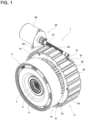
- the two-speed transmission 1 of this example includes an input member 2, an output member 3 arranged coaxially with the input member 2, a planetary gear mechanism 4 arranged between the input member 2 and the output member 3 with respect to the power transmission direction, and a power transmission path switching device 5 that switches the power transmission path between the input member 2 and the output member 3.
- This kind of two-speed transmission 1 is configured to allow switching modes among a low reduction ratio mode in which the reduction ratio between the input member 2 and the output member 3 is small, and a high reduction ratio mode in which the reduction ratio is larger than the low reduction ratio mode, as well as a neutral mode in which torque is not transmitted between the input member 2 and the output member 3, and a parking lock mode in which rotation of the output member 3 is locked.
- the input member 2 is connected to a drive shaft (not illustrated) such as the output shaft of an electric motor, to which torque (power) is input.
- the input member 2 includes an input cylindrical portion 6 and an input flange portion 7 bent toward outside in the radial direction from an end portion on the one side in the axial direction of the input cylindrical portion 6.
- the drive shaft is, for example, internally fitted to the inner circumferential surface of the input cylindrical portion 6 so as to transmit torque, or is coupled to the input flange portion 7 by bolting or the like so as to transmit torque.
- the output member 3 is arranged coaxially with the input member 2 and connected to a driven shaft (not illustrated) such as a differential gear or propeller shaft so as to output torque to the driven shaft.
- the output member 3 includes an output cylindrical portion 9 having a female spline portion 8 on the inner circumferential surface, and an output flange portion 10 bent toward the outside in the radial direction from an end portion on the other side in the axial direction of the output cylindrical portion 9.
- the driven shaft is connected to the output member 3 so as to transmit torque by spline-engaging a male spline portion provided on the outer circumferential surface of a tip end portion of the driven shaft with a female spline portion 8 of the output cylindrical portion 9.
- the planetary gear mechanism 4 is arranged between the input member 2 and the output member 3 with respect to the power transmission direction, and includes a sun gear 11 connected to the input member 2 so as to rotate integrally with the input member 2, a ring gear 12 arranged coaxially with the sun gear 11 around the sun gear 11, a carrier 13 arranged coaxially with the sun gear 11 and connected to the output member 3 so as to rotate integrally with the output member 3, and a plurality of pinion gears 14 that mesh with the sun gear 11 and the ring gear 12 and are supported by the carrier 13 to freely rotate about respective center axes.
- the sun gear 11 is connected to the input member 2 so as to rotate integrally with the input member 2.
- the sun gear 11 includes a small-diameter tubular portion 15 on the one side in the axial direction, a large-diameter tubular portion 16 on the other side in the axial direction, and a flange portion 17 bent toward the outside in the radial direction from an end portion on the other side in the axial direction of the large-diameter tubular portion 16.
- the sun gear 11 includes a sun-side male spline portion 18 on the outer circumferential surface of the large-diameter tubular portion 16, and a gear portion 19 configured by a spur gear or a helical gear on the outer circumferential surface of the flange portion 17.
- the small-diameter tubular portion 15 of the sun gear 11 is externally fitted to the input cylindrical portion 6 of the input member 2 by a structure such as a spline engagement capable of transmitting torque.
- the ring gear 12 includes a ring-side male spline portion 23 on the outer circumferential surfaces of the small-diameter tubular portion 20, and a gear portion 24 configured by a spur gear or a helical gear on the inner circumferential surface of the large-diameter tubular portion 21.
- the carrier 13 is supported coaxially with the sun gear 11 and the ring gear 12, and is connected to the output member 3 so as to rotate integrally with the output member 3.
- the carrier 13 includes a pair of rim portions 25a, 25b each having a circular ring shape that are spaced apart in the axial direction, and column portions 26 extending between the pair of rim portions 25a, 25b at a plurality of locations in the circumferential direction thereof that are aligned with each other, and a cylindrical portion 27 that protrudes over the entire circumference toward the one side in the axial direction from an intermediate portion in the radial direction of a surface on the one side in the axial direction of the rim portion 25a on the one side in the axial direction of the pair of rim portions 25a, 25b.
- the carrier 13 includes circular holes 28a penetrating in the axial direction at a plurality of locations in the circumferential direction of a portion of the rim portion 25a on the one side in the axial direction that is located on the outside in the radial direction than the cylindrical portion 27, and also includes a carrier-side female spline portion 29 on the inner circumferential surface of the cylindrical portion 27. Further, the carrier 13 has circular holes 28b penetrating in the axial direction in portions of the rim portion 25b on the other side in the axial direction of the pair of rim portions 25a, 25b that align with the circular holes 28a of the rim portion 25a on the one side in the axial direction.
- the carrier 13 is configured to rotate integrally with the output member 3 by connecting the rim portion 25b on the other side in the axial direction to the output flange portion 10 of the output member 3 by a structure such as a spline engagement capable of transmitting torque.
- each pinion gear 14 meshes with the sun gear 11 and the ring gear 12 and is supported by the carrier 13 to freely rotate about its own center axis.
- each pinion gear 14 has a column shaped support shaft 30, and a cylindrical body portion 31 rotatably supported around the intermediate portion in the axial direction of the support shaft 30 by a radial needle bearing 32.
- the body portion 31 includes a gear portion 33 on the outer circumferential surface that is configured by a spur gear or a helical gear and meshes with the gear portion 19 of the sun gear 11 and the gear portion 24 of the ring gear 12. End portions on both sides in the axial direction of the support shaft 30 are fitted and fixed into the circular holes 28a, 28b of the carrier 13, respectively.
- a retaining ring 34a is locked to an outer circumferential surface of the intermediate portion in the axial direction of the large-diameter tubular portion 16 of the sun gear 11.
- a spacer 35 is prevented from being displaced to the one side in the axial direction by the retaining ring 34a.
- a surface on the other side in the axial direction of the spacer 35 is abutted against the surface on the one side in the axial direction of the inside portion in the radial direction of the rim portion 25a on the one side in the axial direction through a thrust bearing 36a.
- a retaining ring 34b is locked to an inner circumferential surface of the end portion on the other side in the axial direction of the large-diameter tubular portion 21 of the ring gear 12.
- a retaining plate 37 is prevented from being displaced to the other side in the axial direction by the retaining ring 34b.
- a surface on the one side in the axial direction of the inside portion in the radial direction of the retaining plate 37 is abutted against the surface on the other side in the axial direction of the inside portion in the radial direction of the rim portion 25b on the other side in the axial direction (output flange portion 10 of the output member 3) through a thrust bearing 36b.
- the sun gear 11, ring gear 12, carrier 13, and the pinion gears 14 are prevented from separating when the planetary gear mechanism 4 is assembled.
- the planetary gear mechanism 4 can be handled integrally as a subassembly.
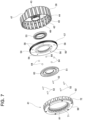
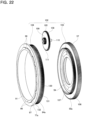
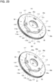
- the power transmission path switching device 5 includes a friction engagement device 40, a rotation transmission state switching device 41, and a control device, and switches the power transmission path between the input member 2 and the output member 3.
- the control device is configured by a cam device 39.
- the power transmission path switching device 5 of this example includes a housing 38 that does not rotate even when in use.
- a radial needle bearing 48 is arranged between the inner circumferential surface of the inner diameter side tubular portion 42 of the housing 38 and the outer circumferential surface of the input cylindrical portion 6 of the input member 2, and a thrust needle bearing 49 is arranged between the surface on the one side in the axial direction of the side plate portion 44 and the surface on the other side in the axial direction of the input flange portion 7, so that the input member 2 is rotatably supported with respect to the housing 38.
- the cam device 39 constituting the control device includes a drive cam 50 that is supported so as to rotate and so as not to displace in the axial direction, a driven cam 51 that is supported so as to rotate and displace in the axial direction relative to the drive cam 50 and displaces in the axial direction as the drive cam 50 rotates, a plurality of (five in the illustrated example) rolling elements 64, and a plurality of (five in the illustrated example) engagement pins 52.
- the inclination angle of the steeply inclined surface portion 54d is set such that the rolling elements 64 can roll down on the steeply inclined surface portion 54d, but cannot ride up on it.
- the inclination angle of the steeply inclined surface portion 54d is such that the rolling elements 64 cannot ride up on it by rotatinally driving the drive cam 50.
- the inclination angle of the gently inclined surface portion 54b and the inclination angle of the first intermediate inclined surface portion 54f and the second intermediate inclined surface portion 54h are all set to a size that allows the rolling elements 64 to roll down or ride up.
- the first intermediate inclined surface portion 54f and the second intermediate inclined surface portion 54h have opposite inclination directions and have the same inclination angle, however the inclination angles can also be made different from each other.
- the inclination angle of the gently inclined surface portion 54b is set to be smaller than the inclination angle of the first intermediate inclined surface portion 54f and the second intermediate inclined surface portion 54h, the inclination angle of the gently inclined surface portion 54b and the inclination angle of the first intermediate inclined surface portion 54f and the second intermediate inclined surface portion 54h can also be made the same.
- the drive cam 50 has cam-side engaging holes 56 that open to the surface on the other side in the axial direction at a plurality of equally spaced locations in the circumferential direction (five locations in the illustrated example) on a portion on the outside in the radial direction, and has a wheel gear portion 57 on the outer circumferential surface that is configured by a helical gear with a helix-shaped tooth trace.
- the drive cam 50 is rotationally driven by the electric actuator 58.
- the electric actuator 58 includes a worm 59 and a variable speed motor 60.
- the worm 59 has a worm gear portion 61 on the outer circumferential surface of the intermediate portion in the axial direction of the electric actuator 58, which meshes with a portion of the wheel gear portion 57 of the drive cam 50 that is exposed from the through hole 47 of the housing 38.
- the variable speed motor 60 rotationally drives the worm 59.
- the drive cam 50 is rotationally driven the variable speed motor 60 through a worm reducer configured by meshing the wheel gear portion 57 and the worm gear portion 61.
- the driven cam 51 is supported so as to rotate and displace in the axial direction relative to the drive cam 50, and displaces in the axial direction as the drive cam 50 rotates.
- the driven cam 51 is arranged at the inside portion in the radial direction of the drive cam 50 so as to face the drive cam 50 in the axial direction.
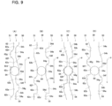
- the driven cam 51 has a driven cam surface 62, which is configured by alternately arranging concave portions and convex portions in the circumferential direction of which the number is the same as that of the concave portions and convex portions of the drive cam surface 54 (five in this example), on the one side in the axial direction of the driven cam 51 facing the drive cam surface 54 of the drive cam 50.
- the driven cam surface 62 is configured by repeatedly arranging a first flat surface portion 62a, a gently inclined surface portion 62b, a first bottom portion 62c, a steeply inclined surface portion 62d, a second flat surface portion 62e, a first intermediate inclined surface portion 62f, a second bottom portion 62g, and a second intermediate inclined surface portion 62h in this order from the other side in the circumferential direction to the one side (from the lower side to the upper side in FIG. 9(A) through FIG. 9(D) ).
- the first flat surface portion 62a and the second flat surface portion 62e are located at the most one side in the axial direction, in other words, at the tip end portion of the convex portion, and the first bottom portion 62c and the second bottom portion 62g are located at the most other side in the axial direction.
- the inclination angle with respect to the virtual plane perpendicular to the center axis of the driven cam 51 increases in the order of the gently inclined surface portion 62b, the first intermediate inclined surface portion 62f and the second intermediate inclined surface portion 62h, and the steeply inclined surface portion 62d.
- the inclination angle of the steeply inclined surface portion 62d is set such that the rolling elements 64 can roll down on the steeply inclined surface portion 62d, but cannot ride up on it.
- the inclination angle of the steeply inclined surface portion 62d is such that the rolling elements 64 cannot ride up on it by rotatinally driving the drive cam 50 by the electric actuator 58.
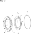
- Each of the second pawl members 74 includes a second base portion 92 and a second engaging pawl 93.
- the second base portion 92 has a substantially columnar shape, and is supported by the pedestal portion 88b of the second holding concave portions 86 so as to pivot about a pivot axis parallel to the center axis of the second member 72.
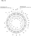
- Each of the first pawl biasing members 75 elastically biases the first engaging pawl 90 of the first pawl member 73 in a direction so as to engage with the engaging concave portions 78 of the first member 71.
- the first pawl biasing member 75 applies a biasing force to the first pawl member 73 in a direction that causes the first pawl member 73 to pivot clockwise in FIG. 14 about the center axis (pivot axis) of the first base portion 89.
- the select plate 77 includes a substantially circular plate-shaped base portion 94 and an annular convex portion 91 that protrudes from the intermediate portion in the radial direction of a surface on the other side in the axial direction of the base portion 94 toward the other side in the axial direction over the entire circumference.
- the base portion 94 has plate-side engaging holes 95 that open on the surface on the one side in the axial direction at a plurality of equally spaced locations in the circumferential direction (five locations in the illustrated example) of the intermediate portion in the radial direction.
- the end portion on the other side in the axial direction of an engagement pin 52 is fitted into each of the plate-side engaging holes 95 without any looseness.
- the select plate 77 rotates integrally with the drive cam 50 (in the same direction and at the same speed).
- the annular convex portion 91 has protruding portions 96 that protrude toward the outside in the radial direction at a plurality of locations in the circumferential direction on the outer circumferential surface.
- the annular convex portion 91 has a gear-shaped uneven portion 97 on the outer circumferential surface, in whih protruding portions 96 and and concave portions are alternately arranged in the circumferential direction.
- the protruding portions 96 configure protruding portions that protrude in the radial direction of the mode select portion.
- the second member 72 is supported and fixed to the housing 38 so as not to relatively rotate and displace in the axial direction.
- the male spline portion 82 provided on the outer circumferential surface (the outer circumferential surface of the base portion 83 and the cylindrical portion 84) of the second member 72 is spline-engaged with the fixed side female spline portion 46 of the housing 38, and the second member 72 and the cover 98 are held from both sides in the axial direction by a pair of retaining ring 101a, 101b that are locked to the inner circumferential surface of the outer diameter side tubular portion 43 of the housing 38 (see FIG. 5 ).
- the rotation transmission state switching device 41 of this example has a free mode in which the first member 71 and the second member 72 can rotate relative to each other in both directions, a lock mode in which the first member 71 and the second member 72 cannot rotate relative to each other, and a one-way clutch mode in which only rotation of the first member 71 in a predetermined direction relative to the second member 72 is allowed.
- the rotation transmission state switching device 41 is configured so as to switch the free mode, the lock mode, and the one-way clutch mode by switching the engagement state between the first engaging pawl 90 of the first pawl member 73 and the engaging concave portions 78 of the first member 71, and the engagement state between the second engaging pawl 93 of the second pawl member 74 and the engaging concave portions 78, based on the rotation of the select plate 77.
- the concave portions of the uneven portion 97 and the first engaging pawl 90 and the second engaging pawl 93 are aligned in phase in the circumferential direction.
- the engaging concave portions 78 of the first member 71 engage with the first engaging pawl 90 and the second engaging pawl 93.
- rotation of the first member 71 with respect to the second member 72 is prevented.
- rotation of the first member 71 with respect to the housing 38 is prevented.
- one of the first engaging pawl 90 and the second engaging pawl 93 engages with the engaging concave portion 78 without being pressed by the protruding portion 96, and by pressing the other of the first engaging pawl 90 and the second engaging pawl 93 by the protruding portion 96 so as not to engage with the engaging concave portions 78, only rotation of the first member 71 in a predetermined direction relative to the second member 72 is allowed and rotation of the first member 71 relative to the second member 72 in a direction opposite to the predetermined direction is prevented.
- the phase in the circumferental direction of the select plate 77 with respect to the second member 72 is adjusted, and as illustrated in FIG. 15(C) , the protruding portion 96 pushes only the second engaging pawl 93 toward outside in the radial direction against the elasticity of the second pawl biasing member 76.
- the engaging concave portion 78 of the first member 71 and the first engaging pawl 90 engage, and the engaging concave portions 78 and the second engaging pawls 93 disengage.
- only rotation of the first member 71 in a predetermined direction (clockwise direction in FIG. 15(C) ) with respect to the second member 72 is allowed, and rotation in a direction opposite to the predetermined direction (counterclockwise direction in FIG. 15(C) ) is prevented.
- the rotation transmission state switching device 41 functions as a ratchet type one-way clutch.
- the predetermined direction coincides with the normal rotation direction of the input member 2.
- the normal rotation direction of the input member 2 refers to the direction of rotation of the input member 2 when moving the automobile forward.
- the power transmission path switching device 5 of this example switches the operation mode thereof by displacing the driven cam 51 in the axial direction based on rotationally driving the drive cam 50 by the electric actuator 58 so as to switch the connection/disconnection state of the friction engagement device 40, and, at the same time, by adjusting the phase of the select plate 77 in the circumferential direction with respect to the second member 72 so as to switch the mode of the rotation transmission state switching device 41.
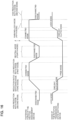
- the power transmission path switching device 5 includes a first mode in which the friction engagement device 40 is connected and the rotation transmission state switching device 41 is in the free mode, a second mode in which the friction engagement device 40 is disconnected and the rotation transmission state switching device 41 is in the lock mode, a third mode which is established during switching of the friction engagement device 40 from the disconnected state to the connected state and the rotation transmission state switching device 41 is set to the one-way clutch mode, a fourth mode in which the friction engagement device 40 is disconnected and the rotation transmission state switching device 41 is set to the free mode, and a fifth mode in which the friction engagement device 40 is connected and the rotation transmission state switching device 41 is set to the lock mode.
- each mode will be explained.
- the friction engagement device 40 is connected and the rotation transmission state switching device 41 is set to the free mode based on rotationally driving the drive cam 50 by the electric actuator 58.
- the rolling elements 64 are caused to ride on the first flat surface portion 54a of the drive cam surface 54 and the first flat surface portion 62a of the driven cam surface 62 and the driven cam 51 is displaced toward a direction (the other side in the axial direction) in which the distance from the drive cam 50 in the axial direction increases.
- the separate plate 66 that is located at the most one side in the axial direction is pressed toward the other side in the axial direction through the elastic member 68 and the thrust rolling bearing 69.
- the friction plate 65 and the separate plate 66 are pressed against each other and the friction engagement device 40 is connected (the fastening force of the friction engagement device 40 increases), so that the sun gear 11 and the carrier 13 begin to rotate integrally.
- the first engaging pawl 90 is pushed toward outside in the radial direction and the second engaging pawl 93 is pushed toward outside in the radial direction by the protruding portion 96.
- the engaging concave portions 78 of the first member 71 disengage from the first engaging pawl 90 and the second engaging pawl 93, and the rotation transmission state switching device 41 is switched to the free mode in which rotation of the first member 71 relative to the second member 72 is allowed regardless of the direction of relative rotation between the first member 71 and the second member 72.
- the driven cam 51 is displaced toward a direction (the one side in the axial direction) in which the distance in the axial direction from the drive cam 50 is shortened by moving the rolling elements 64 to the first bottom portion 54c of the drive cam surface 54 and the first bottom portion 62c of the driven cam surface 62.
- the force pressing the friction plate 65 and the separate plate 66 against each other is released.
- the friction plate 65 and the separate plate 66 rotate in the same direction while sliding (brought into sliding contact) both side surfaces in the axial direction of the friction plates 65 and both side surfaces in the axial direction of the separate plates 66, and gradually become synchronized (rotation speed gradually matches).
- the engaging concave portions 78 of the first member 71 are disengaged from the first engaging pawl 90 and the second engaging pawl 93, and the rotation transmission state switching device 41 is switched to the free mode in which rotation of the first member 71 relative to the second member 72 is allowed regardless of the direction of relative rotation between the first member 71 and the second member 72.
- the direction of rotation and the rotation speed of the sun gear 11, the ring gear 12, and the carrier 13 are the same, and the entire planetary gear mechanism 4 rotates as one, in other words, it is in a so-called glued state. Therefore, the power of the input member 2 is transmitted to the output member 3 through via a path passing through the input member 2, the carrier 13, and the output member 3 in this order.
- the power transmission path switching device 5 of this example is configured to rotate the select plate 77 by rotating the drive cam50 by one electric actuator 58 (variable speed motor 60) so as to switch the coonection/disconnection state of the friction engagement device 40 and the mode of the rotation transmission state switching device 41.
- switching the connection/disconnection state of the friction engagement device and switching the mode of the rotation transmission state switching device can also be done by separate actuators.
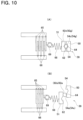
- the power transmission path switching device 5z of the comparative example switches the connection/disconnection states of the first friction engagement device 40a and the second friction engagement device 40b.
- the first driven cam 51a and the second driven cam 51b are displaced in different phases as the drive cam 50z rotates (displaced (move forward and backward) in opposite directions in the axial direction).
- the fastening force of the second friction engagement device 40b cannot be made sufficiently large at the moment when the direction of the torque applied to the ring gear 12 is reversed and the direction of revolution of the pinion gears 14 and the direction of rotation of the ring gear 12 match. Due to this, the ring gear 12 is dragged with respect to the housing 38 and torque loss occurs between the ring gear 12 and the housing 38.
- the vehicle hardly travels at high speed during rotation of the input member 2 in the reverse direction, that is, when the automobile is moving backward. Therefore, when the input member 2 is rotating in the reverse direction, there is little need to make the reduction ratio switching mode selectable in the power transmission path switching device 5 when switching from the high reduction ratio mode to the low reduction ratio mode. Further, when switching the low reduction ratio mode to the high reduction ratio mode, the vehicle is mainly in a deceleration state. In this state, power is not transmitted from the input member 2 to the output member 3, therefore, there is little need to select the reduction ratio switching mode in the power transmission path switching device 5.
- the rotation transmission state switching device 41 is switched to the lock mode while maintaining the friction engagement device 40 in a connected state after connecting the friction engagement device 40.
- the two-speed transmission 1 when releasing the two-speed transmission 1 from the parking lock mode, the two-speed transmission 1 is switched to the high reduction ratio mode by disconnecting the friction engagement device 40 while maintaining the rotation transmission state switching device 41 in the lock mode.
- the rolling elements 64 are moved so as to roll down the steeply inclined surface portions 54d, 62d from the second flat surface portion 54e of the drive cam surface 54 and the second flat surface portion 62e of the driven cam surface 62 and moved to the first bottom portions 54c, 62c.
- the driven cam 51 is displaced in a direction in which the distance in the axial direction from the drive cam 50 is shortened, and the force pressing the friction plate 65 and the separate plate 66 against each other is released.
- the two-speed transmission 1 is switched to the high reduction ratio mode by switching the power transmission path switching device 5 to the second mode in which the friction engagement device 40 is disconnected and the rotation transmission state switching device 41 is in the lock mode.
- any of the modes of the low reduction ratio mode, the high reduction ratio mode, the reduction ratio switching mode, and the neutral mode is switched to the parking lock mode, and then the drive cam 50 is rotationally driven in the same direction ⁇ while the parking lock mode is released and switched to the high reduction ratio mode.
- the drive cam 50 is further rotated and the phase of the select plate 77 in the circumferential direction with respect to the second member 72 is adjusted.
- the protruding portion 96 is located in a portion separated from the first engaging pawl 90 of the first pawl member 73 and the second engaging pawl 93 of the second pawl member 74 in the circumferential direction.
- the first engaging pawl 90 and the second engaging pawl 93 are displaced toward the inside in the radial direction by the elasticity of the first pawl biasing member 75 and the second pawl biasing member 76 respectively, and try to engage with the engaging concave portions 78.
- the first engaging pawl 90 and the second engaging pawl 93 are prevented from displacing toward the inside in the radial direction by the convex portion 79 of the first member 71, and are prevented from engaging with the engaging concave portions 78.
- switching of the rotation transmission state switching device 41 to the lock mode during rotation of the output member 3 can be prevented, and the two-speed transmission 1 can be prevented from inadvertently switched to the parking lock mode while the vehicle is traveling.
- the two-speed transmission 1 when releasing the two-speed transmission 1 from the parking lock mode, the two-speed transmission 1 is switched to the high reduction ratio mode by disconnecting the friction engagement device 40 while maintaining the rotation transmission state switching device 41 in the lock mode. Therefore, even when the parking lock mode is released from a state in which a large torque is applied to the output member 3, the force required for the release is prevented from becoming excessively large. In the following, the reason for this will be explained.
- the parking lock mode of the two-speed transmission 1 is released, while maintaining the rotation transmission state switching device 41 in the lock mode, by displacing the driven cam 51 in the axial direction based on the rotation of the drive cam 50 and disconnecting the friction engagement device 40. Therefore, even when the parking lock mode is released from a state where a large torque is applied to the output member 3, the force required for the release is prevented from becoming large, and the releasing performance of the parking lock can be easily secured. Specifically, for example, the parking lock mode of the two-speed transmission 1 can be released even when the vehicle is loaded with a maximum load and stopped on a steep slope.
- the inclination angle of the steeply inclined surface portion 54d of the drive cam surface 54 and the steeply inclined surface portion 62d of the driven cam surface 62 is set to a size such that the rolling elements 64 cannot ride up by rotatinally driving the drive cam 50 by the electric actuator 58. Therefore, the two-speed transmission 1 can be prevented from being switched to the parking lock mode even if a failure occures when the two-speed transmission 1 is in the high reduction ratio mode and the vehicle is traveling at low speed.
- the two-speed transmission 1 of this example it is possible to prevent the mode from being inadvertently switched to the parking lock mode while the vehicle is traveling, and to ensure the releasing performance of the parking lock.
- the two-speed transmission 1 of this example includes the neutral mode in which torque is not transmitted between the input member 2 and the output member 3, the electricity consumption performance of the electric vehicle equipped with the two-speed transmission 1 can be improved. In the following, the reason for this will be explained.
- a power distributed four-wheel drive system in which a pair of front wheels is rotationally driven by one electric motor and a pair of rear wheels is rotationally driven by another electric motor.
- a pair of front wheels is rotationally driven by one electric motor
- a pair of rear wheels is rotationally driven by another electric motor.
- the other wheels that are not rotationally driven are connected to the electric motor so as to transmit torque, a loss due to dragging occurs in the electric motor, resulting in a problem of deteriorated electricity consumption performance.
- the two-speed transmission 1 of this example includes the neutral mode in which torque is not transmitted between the input member 2 and the output member 3.
- a pair of wheels for example, the pair of rear wheels
- the electric motor are dynamically separated by switching the two-speed transmission 1 mounted between the pair of wheels and the electric motor to the neutral mode.
- the drive wheels and the driving source can be dynamically separated and the distance traveled by coasting can be increased by switching the two-speed transmission 1 to the neutral mode. In other words, speed reduction during coasting can be slowed down. As a result, the electricity consumption performance of the vehicle (electric vehicle) mounted with the two-speed transmission 1 can be improved.
- a structure capable of dynamically separating the drive wheels and the driving source as needed can be achieved without providing a dedicated clutch device between the drive wheels and the driving source. Therefore, the structure of the drive system of the electric vehicle can be simplified, and manufacturing costs can be reduced.
- the neutral mode in which torque is not transmitted between the input member 2 and the output member 3 is arranged between the low reduction ratio mode in which the reduction ratio between the input member 2 and the output member 3 is small and the parking lock mode in which the rotation of the output member 3 is locked.
- the two-speed transmission 1 of this example can only be switched to the neutral mode from the low reduction ratio mode or the parking lock mode, and it is not possible to be switched directly from the high reduction ratio mode (and the reduction ratio switching mode) to the neutral mode (without going through the low reduction ratio mode or the parking lock mode).
- the second bottom portion 54g where the rolling elements 64 are located when the neutral mode is selected is arranged in the circumferential direction between the first flat surface portion 54a where the rolling elements 64 are located when the low reduction ratio mode is selected and the second flat surface portion 54e where the rolling elements 64 are located when switched to the parking lock mode.
- the mode is switched from the low reduction ratio mode, the neutral mode, and to the parking lock mode in this order.
- the second intermediate inclined surface portion 54h is arranged between the second bottom portion 54g and the first flat surface portion 54a, and the first intermediate inclined surface portion 54f is arranged between the second bottom portion 54g and the second flat surface portion 54e.
- the first intermediate inclined surface portion 54f is a portion where the rolling elements 64 move during switching between the neutral mode and the low reduction ratio mode
- the second intermediate inclined surface portion 54h is a portion where the rolling elements 64 move during switching between the neutral mode and the parking lock mode
- the neutral mode is arranged between the low reduction ratio mode and the parking lock mode, for example, it is possible to prevent an excessive load from being applied to the electric motor when switching the two-speed transmission 1 to the neutral mode in order to shift to coasting while driving at high speed. In the following, the reason for this will be explained.
- the neutral mode is arranged between the high reduction ratio mode in which the reduction ratio is larger than the low reduction ratio mode and the parking lock mode.
- the neutral mode when switching to the neutral mode, either the high reduction ratio mode or the parking lock mode is passed through.
- the wheels are not locked since the first engaging pawl 90 and the second engaging pawl 93 of the rotation transmission state switching device 41 are prevented from displacing in the inside in the radial direction and do not engage with the engaging concave portions 78.
- abnormal noise may be generated when the convex portion 79 of the first member 71 flick the first engaging pawl 90 and the second engaging pawl 93.
- the rotational speed of the output member 3 is smaller than a predetermined value, there is a possibility that the wheels may be locked. Considering this, when switching the two-speed transmission 1 to the neutral mode while the vehicle is traveling, it is not preferable to go through the parking lock mode.
- the neutral mode is arranged between the low reduction ratio mode and the parking lock mode, it is possible to switch from the low reduction ratio mode to the neutral mode when switching the two-speed transmission 1 to the neutral mode while the vehicle is traveling. Therefore, it is possible to prevent an excessive load from being applied to the electric motor due to the number of rotations of the electric motor rapidly increasing or becoming excessively high when switching to the neutral mode.
- an elastic member 68 is arranged between the separate plate 66 that is located at the most one side in the axial direction and the driven cam 51. Therefore, assembly errors of the power transmission path switching device 5 and deviations due to wear of the friction plate 65 and the separate plate 66 can be absorbed by the elastic members 68. Therefore, by controlling the force that presses the driven cam 51 (the pressing force of the driven cam 51 toward the other side in the axial direction with respect to the separate plate 66 that is located at the most one side in in the axial direction), the fastening force of the friction engagement device 40 can be controlled. As a result, sufficient fastening force of the friction engagement device 40 can be ensured in the low reduction ratio mode.
- the rolling elements 64 ride up the first flat surface portion 54a or the second flat surface portion 54e of the drive cam surface 54. Therefore, according to the power transmission path switching device 5 of this example, the friction engagement device 40 is maintained in the connected state even when the power supply to the variable speed motor 60 is stopped after the mode switching is completed, and from this aspect as well, electricity consumption performance can be improved.
- the friction engagement device 40 can be maintained in the connected state even after the power supply to the variable speed motor 60 is stopped.
- the planetary gear mechanism 4 is arranged around the output member 3 and the power transmission path switching device 5 is arranged around the input member 2
- various configurations can be adopted, not limited to this.
- the planetary gear mechanism can be arranged around the input member and the power transmission path switching device can be arranged around the output member.
- the planetary gear mechanism and/or the power transmission path switching device can be arranged without overlapping the input member or the output member in the radial direction. In any case, the shape of each component is appropriately changed in accordance with the respective configuration.
- the rolling elements 64 are held between the drive cam 50 and the driven cam 51.
- the cam device is not limited to the configuration of this example, and various configurations can be adopted as long as the driven cam can be displaced in the axial direction based on the rotation of the drive cam.
- the drive cam surface provided on the drive cam and the driven cam surface provided on the driven cam can also be brought into direct sliding contact.
- the second member 72 is arranged around the first member 71 and the first pawl member 73 and the second pawl member 74 are pivotally supported with respect to the second member 72.
- the rotation transmission state switching device is not particularly limited as long as it has a structure that can switch the rotation transmission state between the first member and the second member.
- the first pawl member and the second pawl member may be pivotally supported with respect to the first member arranged on the inside in the radial direction, or the first member and the second member may be arranged to face each other in the axial direction.
- the rotation transmission state switching device 41 of this modification example does not have a one-way clutch mode in which only rotation of the first member 71 in a predetermined direction relative to the second member 72 is allowed.
- the rotation transmission state switching device 41 of this modification example only has a free mode in which the first member 71 and the second member 72 can rotate relative to each other in both directions, and a lock mode in which the first member 71 and the second member 72 cannot rotate relative to each other.
- the rotation transmission state switching device 41 is configured so as to switch between two modes, the free mode and the lock mode, by adjusting the installation position in the circumferential direction and the length in the circumferential direction of the protruding portion 96 of the select plate 77.
- the two-speed transmission 1 of this modification example does not have a one-way clutch mode
- the high reduction ratio mode, the low reduction ratio mode, the neutral mode, and the parking lock mode are switched based on rotationally driving one drive cam 50 by one electric actuator 58.
- the friction engagement device 40 is switched from the disconnected state to the connected state after the rotation transmission state switching device 41 is switched from the lock mode to the free mode when switching from the high reduction ratio mode to the low reduction ratio mode.
- the two-speed transmission 1 can be switched to the high reduction ratio mode, the reduction ratio switching mode, the low reduction ratio mode, the neutral mode, and the parking lock mode by switching the friction engagement device 40 between the connected and disconnected states and switching the rotation transmission state switching device 41 between two modes. Therefore, according to the two-speed transmission 1 of this modification example, control can be simplified compared to the two-speed transmission 1 of the first example.
- the power transmission path switching device 5a of this example includes a reducer 102 between the drive cam 50a and the select plate 77a, which reduces the number of rotations of the drive cam 50a and transmits the rotation to the select plate 77a.
- the power transmission path switching device 5a of this example does not include the engagement pins 52 spanned between the drive cam 50 and the select plate 77, and the rotation of the drive cam 50a is transmitted to the select plate 77a through the reducer 102.
- the reducer 102 includes a cam-side gear portion 103 provided on the drive cam 50a, a plate-side gear portion 104 provided on the select plate 77a, and a two-speed gear 105.
- the drive cam 50a has a substantially circular plate shape, and includes a base portion 106 having the drive cam surface 54 on the inside portion in the radial direction of the surface on the other side in the axial direction, and a cylindrical portion 107 that protrudes from the intermediate portion in the radial direction of the surface on the other side in the axial direction of the base portion 106 toward the other side in the axial direction over the entire circumference. Further, the drive cam 50a has a cam-side gear portion 103 on the outer circumferential surface of the cylindrical portion 107 over the entire circumference.
- the select plate 77a includes a stepped cylindrical base portion 94a, and an annular convex portion 91 that protrudes over the entire circumference from the intermediate portion in the radial direction of the surface on the other side in the axial direction of the base portion 94a toward the other side in the axial direction.
- the base portion 94a has a small diameter portion 130 on the one side in the axial direction and a large diameter portion 131 on the other side in the axial direction.
- the select plate 77a has a plate-side gear portion 104 over the entire circumference on the outer circumferential surface of the small diameter portion 130.
- the plate-side gear portion 104 has a pitch diameter larger than that of the cam-side gear portion 103, and has a greater number of teeth than the cam-side gear portion 103.
- the two-speed gear 105 has a first gear portion 108 that meshes with the cam-side gear portion 103 and a second gear portion 109 that meshes with the plate-side gear portion 104.
- the first gear portion 108 has a pitch diameter larger that of the second gear portion 109 and has a greater number of teeth than the second gear portion 109.
- the two-speed gear 105 of this example has a center axis 110 supported with respect to the housing 38a and a body portion 111 which has the first gear portion 108 over the entire circumference of the outer circumferential surface of the portion on the one side in the axial direction and has the second gear portion 109 over the entire circumference of the outer circumferential surface of the portion on the other side in the axial direction and is supported around the center axis 110 so as to rotate freely.
- the allowable load torque of the rotation transmission state switching device 41a can be sufficiently ensured without using a particularly high output motor as the variable speed motor 60. The reason for this will be explained in comparison with the power transmission path switching device 5 of the first example.
- the rotation transmission path switching device 5 of the first example in order to sufficiently secure the allowable load torque of the rotation transmission state switching device 41, it is effective to increase the number of the first pawl members 73 and the second pawl members 74. However, when the number of the first pawl members 73 and the second pawl members 74 is increased, the rotation angle of the drive cam 50 when switching between the first mode and the second mode becomes smaller.
- the power transmission path switching device 5a of this example includes the reducer 102 between the drive cam 50a and the select plate 77a. Therefore, the rotation angle of the select plate 77a per rotation of the drive cam 50a can be made smaller than the rotation angle of the driven cam 51 per rotation of the drive cam 50a. Therefore, it is not necessary to increase the inclination angle of the gently inclined surface portion 54b and/or the gently inclined surface portion 62b in order to ensure a sufficient amount of displacement in the axial direction of the driven cam 51 even when the number of the first pawl members 73 and the second pawl members 74 is increased in order to sufficiently secure the allowable load torque of the rotation transmission state switching device 41a. In short, there is no need to use a particularly high output motor as the variable speed motor 60.
- the configuration and operational effects of the other parts of the second example are the same as those of the first example.
- the third example of an embodiment of the present disclosure will be explained with reference to FIG. 23(A) through FIG. 28 .
- the structure of the cam device 39a constituting the control device is changed from the structure of the cam device 39 of the first example.
- the cam device 39a includes a drive cam 50b, a driven cam 51c, a plurality of engagement pins 52 (see, for example, FIG. 5 through FIG. 7 ), a plurality of (three in the illustrated example) rolling elements 64a.
- rollers are used as the rolling elements 64a.
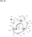
- the cam device 39a has a lock release prevention mechanism 123 which prevents the rotation transmission state switching device 41 from being switched to the one-way clutch mode while the friction engagement device is connected from a state where the friction engagement device 40 (see, for example, FIG. 2 and FIG. 5 ) is connected and the rotation transmission state switching device 41 is in the lock mode, that is, from a state where the two-speed transmission 1 is in the parking lock mode.
- the drive cam 50b is configured in the shape of a hollow circular plate shape, and has a drive cam surface 54 on the inside portion in the radial direction of the surface on the other side in the axial direction, in which the same number of concave portions and convex portions are arranged alternately in the circumferential direction. Further, the drive cam 50b has cam-side engaging holes 56 that open to the surface on the other side in the axial direction at a plurality of equally spaced locations in the circumferential direction of the portion on the outside in the radial direction, and has a wheel gear portion 57 on the outer circumferential surface.
- the drive cam 50b has protrusions 112 that protrude toward the other side in the axial direction at a plurality of locations in the circumferential direction (three locations in the illustrated example) of the intermediate portion in the radial direction of the surface on the other side in the axial direction.
- each of the protrusion 112 has a substantially right triangular side surface shape when viewed from the radial direction.
- the protrusion 112 has a gently inclined surface portion 112a on one side in the circumferential direction that is inclined toward the other side in the axial direction as going from the one side to the other side in the circumferential direction, and a stopper surface portion 112b on the surface on the other side in the circumferential direction that is substantially perpendicular to the portion of the surface on the other side in the axial direction of the drive cam 50b that is separated from the drive cam surface 54, the cam-side engaging holes 56, and the protrusions 112.
- the drive cam 50b is supported on the outer circumferential surface of the end portion on the one side in the axial direction of the inner diameter side tubular portion 42 of the housing 38 (see, for example, FIG. 2 and FIG. 5 ) through the angular ball bearing 53 so as to rotate freely and so as not to displace in the axial direction.
- the driven cam 51c are configured in the shape of a substantially hollow circular plate shape and has rectangular holes 113 that are arranged at a plurality of locations in the circumferential direction (three locations in the illustrated example that are equally spaced in the circumferential direction) of the portion on the outside in the radial direction and penetrating in the axial direction, and substantially semicircular plate-shaped support plate portions 114a, 114b that protrude from portions on both sides of each rectangular hole 113 toward the one side in the axial direction.
- Each of the support plate portions 114a on the outside in the radial direction includes a support hole 115 which is a circular hole penetrating in the radial direction, and each of the support plate portions 114b on the inside in the radial direction includes a support concave portion 116 having a circular opening on the surface on the outside in the radial direction.
- the driven cam 51c has ear portions 117 at a plurality of locations in the circumferential direction (three locations in the illustrated example) that protrude more toward the outside in the radial direction than portions adjacent on both sides in the circumferential direction, and has concave portions 118 that are concaved toward the other side in the axial direction on the surface on the one side in in the axial direction of the ear portions 117.
- Rectangular flat plate-shaped stopper pieces 119 are respectively supported in the concave portions 118 so as to pivot around the base end portion.
- each of the stopper pieces 119 is supported by the inner surface of each of the concave portions 118 so as to pivot around the pivot axis that extends in the radial direction centered on the center axis of the driven cam 51c.
- a biasing member 120 is held between the bottom surface of the concave portion 118 and the stopper piece 119.
- the tip end portion of the stopper piece 119 is elastically biased in a direction in which the angle between the stopper piece 119 and a surface on the one side in the axial direction of the driven cam 51c becomes larger.
- the biasing member 120 can be configured by a coil spring, a leaf spring, rubber, or other elastomer or the like.
- the driven cam 51c is supported by spline-engaging the driven-side female spline portion 63 provided on the inner circumferential surface with the fixed side male spline portion 45 of the housing 38 so as to displace only in the axial direction with respect to the housing 38.
- Each of the rolling elements 64a has a cylindrical shape, and is supported so as to rotate freely with respect to the support plate portions 114a, 114b of the driven cam 51c through a column shaped support shaft 121 and a plurality of rollers 122.
- the end portion on one side in the axial direction of the support shaft 121 (the end portion on the outside in the radial direction around the center axis of the driven cam 51c) is fitted and fixed into the support hole 115 of the support plate portion 114a on the outside in the radial direction
- the end portion on the other side in the axial direction of the support shaft 121 (the end portion on the inside in the radial direction around the center axis of the driven cam 51c) is fitted and fixed into the support concave portion 116 of the support plate portion 114b on the inside in the radial direction.
- each rolling element 64a In a state where the rolling elements 64a are supported by the driven cam 51c, portions on the other side in the axial direction of the rolling elements 64a are arranged inside the rectangular holes 113. Further, the outer circumferential surface of each rolling element 64a is in rolling contact with the drive cam surface 54 provided on the surface on the other side in in the axial direction of the drive cam 50b.
- rollers are used as the rolling elements 64a, and the rolling elements 64a are supported so as to rotate (spin) freely around the rotation axis C facing in the radial direction centered on the center axis of the driven cam 51c. Therefore, the driven cam 51c can be reliably displaced in the axial direction based on rotating the drive cam 50b.
- balls are used as the rolling elements 64 in the cam device 39 of the first example, when the drive cam 50 is rotated, there is a possibility that slippage may occur at the rolling contact portion between the surface of the rolling elements 64 and the drive cam surface 54 and/or the driven cam surface 62.
- protrusions 112 are provided on the drive cam 50b, stopper pieces 119 are pivotally supported on the driven cam 51c, and the tip end portion of each stopper piece 119 is biased by a biasing member 120. Therefore, the rotation transmission state switching device 41 is prevented from being switched from the lock mode to the one-way clutch mode while the friction engagement device 40 is connected from a state where the friction engagement device 40 is connected and the rotation transmission state switching device 41 is set to the lock mode.
- the lock release prevention mechanism 123 is configured by the protrusions 112, the stopper pieces 119, and the biasing members 120, for preventing from switching from a state where the friction engagement device 40 is connected and the rotation transmission state switching device 41 is set to the lock mode to a state where the rotation transmission state switching device 41 is set from the lock mode to the one-way clutch mode while the friction engagement device 40 is connected.
- the zero point of the drive cam 50b can also be corrected in a state where the stopper surface portions 112b of the protrusions 112 provided on the drive cam 50b are abutted against the tip end portions of the stopper pieces 119 supported by the driven cam 51c.
- the increase in the discrepancy can be suppressed by abutting the stopper surface portions 112b of the protrusions 112 provided on the drive cam 50b against the tip end portions of the stopper pieces 119 supported by the driven cam 51c in a state where the two-speed transmission 1 is switched to the parking lock mode so as to correct the zero point of the drive cam 50b.
- the configuration and operational effects of the other parts of the third example are the same as those of the first example.
- FIG. 29 A fourth example of an embodiment of the present disclosure will be explained with reference to FIG. 29 .
- the friction engagement device 40 is prevented from being inadvertently disconnected or the rotation transmission state switching device 41 is prevented from being inadvertently switched to the one-way clutch mode from a state where the two-speed transmission 1 (see, for example, FIG. 1 and FIG. 2 ) is in the parking lock mode.
- convex portions 124 protruding toward the other side in the axial direction are provided on both sides in the circumferential direction of the portion of the first flat surface portion 54a of the drive cam surface 54 where the rolling elements 64 are located when the two-speed transmission 1 is in the parking lock mode.
- the convex portions 124 have a height in the axial direction that allows the rolling element 64 to ride over the convex portions 124 based on rotationally driving the drive cam 50 by the electric actuator 58.
- the rolling elements 64 interfere (caught) with the convex portions 124.
- the rolling elements 64 are prevented from rolling inadvertently, and the friction engagement device 40 is prevented from being inadvertently disconnected or the rotation transmission state switching device 41 is prevented from being inadvertently switched to the one-way clutch mode.
- the convex portions 124 for preventing the rolling elements 64 from rolling inadvertently may be provided on the driven cam surface 62 of the driven cam 51 in place of or in addition to the drive cam surface 54 of the drive cam 50. Further, the structure of this example can also be implemented in combination with the lock release prevention mechanism 123 of the third example. The configuration and operational effects of the other parts of the fourth example are the same as those of the first example.
- a fifth example of an embodiment of the present disclosure will be explained with reference to FIG. 30 through FIG. 31(B) .
- a so-called normally closed type clutch is used as the friction engagement device 40c of the power transmission path switching device 5b, which is connected in a state where the power supply to the electric actuator 58 (see FIG. 1 and FIG. 2 ) is stopped in a stand-alone state and disconnected by increasing the distance in the axial direction between the drive cam 50 and the driven cam 51 based on energizing the electric actuator 58, and the friction engagement device 40c is arranged between the sun gear 11 and the ring gear 12.
- the friction engagement device 40c has a plurality of friction plates 65 and a plurality of separate plates 66.
- Each friction plate 65 is supported so as to displace only in the axial direction with respect to the sun gear 11.
- Each separate plate 66 is supported so as to displace only in the axial direction with respect to the ring gear 12.
- the friction engagement device 40c switches the connection/disconnection state by pressing the separate plate 66 that is located at the most other side in the axial direction toward the one side in the axial direction or by releasing the pressing force by the cam device 39 thruogh the pressing member 125.
- the pressing member 125 has a cylindrical portion 126 that is supported around the input member 2 so as to be abe to rotate freely with respect to the input member 2, a flange portion 127 that is bent toward the outside in the radial direction from the end portion on the other side in the axial direction of the cylindrical portion 126, and a plate pressing portion 128 that is bent toward the one side in in the axial direction from the end portion on the outside in the radial direction of the flange portion 127.
- a thrust rolling bearing 69a is held between the end portion on the one side in the axial direction of the cylindrical portion 126 and the driven cam 51.
- the cam device 39 is capable of pressing the pressing member 125 toward the other side in the axial direction through the thrust rolling bearing 69a.
- An elastic member 129 is held between the surface on the other side in the axial direction of the flange portion 127 and a portion fixed to the housing 38 (see FIG. 1 and FIG. 2 ).
- the elastic member 129 elastically biases the pressing member 125 toward the one side in the axial direction.
- the elastic member 129 can be configured by a disc spring, a coil spring, or the like.
- the tip end portion (the end portion on the one side in the axial direction) of the plate pressing portion 128 faces the surface on the other side in the axial direction of the separate plate 66 that is located at the most other side in the axial direction.
- the friction engagement device 40c switches the connection/disconnection state by displacing the driven cam 51 in the axial direction based on rotationally driving the drive cam 50 by the electric actuator 58.
- the driven cam 51 is displaced in a direction (the one side in the axial direction) in which the distance in the axial direction from the drive cam 50 is shortened by moving the rolling elements 64 to the bottom portion 54i of the drive cam surface 54 and the bottom portion 62i of the the driven cam surface 62.
- the pressing member 125 is elastically pressed toward the one side in the axial direction due to the action of the elastic member 129, and the separate plate 66 that is located at the most other side in the axial direction is pressed toward the one side in the axial direction by the tip end portion of the plate pressing portion 128.
- the friction plate 65 and the separate plate 66 are pressed against each other, and the friction engagement device 40c is connected (the fastening force of the friction engagement device 40c becomes large).
- the driven cam 51 is displaced in a direction in which the distance from the drive cam 50 in the axial direction increases (the other side in the axial direction) by moving the rolling elements 64 to the flat surface portion 54j of the drive cam surface 54 and the flat surface portion 62j of the driven cam surface 62.
- the pressing member 125 is pressed toward the other side in the axial direction against the elasticity of the elastic member 129.
- the mode of the rotation transmission state switching device 41 is switched.
- the operation mode of the power transmission path switching device 5a is switched, and the two-speed transmission 1a can be switched among the low reduction ratio mode, the high reduction ratio mode, the reduction ratio switching mode, and the parking lock mode.
- the number and arrangement of the bottom portion 54i and the flat surface portion 54j of the drive cam surface 54, the inclination angle of the inclined surface portion that connects the bottom portion 54i and the flat surface portion 54j, the number and arrangement of the bottom portion 62i and the flat surface portion 62j of the driven cam surface 62, the inclination angle of the inclined surface portion that connects the bottom portion 62i and the flat surface portion 62j, and so on, are appropriately determined depending on the timing of switching the connection/disconnection state of the friction engagement device 40c.
- the configuration and operational effects of the other parts of the fifth example are the same as those of the first example.
Landscapes
- Engineering & Computer Science (AREA)
- General Engineering & Computer Science (AREA)
- Mechanical Engineering (AREA)
- Physics & Mathematics (AREA)
- Electromagnetism (AREA)
- Gear-Shifting Mechanisms (AREA)
- Structure Of Transmissions (AREA)
- Mechanical Operated Clutches (AREA)
Abstract
Description
- The present disclosure relates to a power transmission path switching device for switching the transmission path of power between an input member and an output member, and a two-speed transmission equipped with the power transmission path switching device.
- In response to the recent trend toward reducing fossil fuel consumption, electric and hybrid vehicles have been studied and and partially implemented. Unlike internal combustion engines (engines) that operate by direct combustion of fossil fuels, electric motors, which are the power source of electric and hybrid vehicles, do not necessarily need to be provided with a transmission like general automobiles that use internal combustion engines as their driving source since the torque and rotation speed characteristics of the output shaft are favorable for automotive use (generally, maximum torque is generated at startup). However, even when an electric motor is used as the driving source, acceleration and high-speed performance can be improved by providing a transmission. Specifically, by providing a transmission, the relationship between the traveling speed of the vehicle and acceleration can be made smooth, similar to that of an automobile with a gasoline engine and a transmission in the power transmission system. This point will be explained with reference to
FIG. 32 . - For example, if a power transmission device with a large reduction ratio is arranged between the output shaft of the electric motor and the input section of the differential gear connected to the drive wheels, the relationship between acceleration (G) and traveling speed (km/h) of the electric vehicle becomes as indicated by the solid line a in
FIG. 32 . In other words, although the acceleration performance at low speed is excellent, driving at high speed becomes impossible. On the other hand, if a power transmission device with a small reduction ratio is arranged between the output shaft and the input section, this relationship becomes as indicated by the chain line b inFIG. 32 . In other words, although driving at high speed becomes possible, acceleration performance at low speed is impaired. Regarding this, if a transmission is provided between the output shaft and the input section and the reduction ratio of this transmission is changed according to the vehicle speed, a characteristic can be obtained in which the portion of the solid line a to the left of the point P and the portion of the chain line b to the right of the point P are continuous. This characteristic is almost the same as that of a gasoline engine vehicle with similar power output, which is indicated by the dashed line c inFIG. 32 , and it can be seen that in terms of acceleration and high-speed performance, performance equivalent to that of a gasoline engine vehicle provided with a transmission in the power transmission system can be obtained. -
JPH 05-116549(A -
German Patent Application Publication No. 102016105991 discloses a structure of a shift drum device capable of switching the reduction ratio of the transmission in at least two levels. In this device, the reduction ratio of the transmission can be switched based on rotating the shift drum by an actuator such as an electric motor. -
- Patent Literature 1:
JPH 05-116549 A - Patent Literature 2:
German Patent Application Publication No. 102016105991 - The device discribed in
JPH 05-116549 A - The device described in
German Patent Application Publication No. 102016105991 is capable of switching to the parking lock mode, which locks the rotation of the output shaft of the transmission, and includes a mechanism that prevents the transmission from inadvertently switching to the parking lock mode while the vehicle is traveling and applying an undesired load to the transmission. Specifically, by engaging a pin with a groove formed on the outer circumferential surface of the shift drum and extending in the circumferential direction, unintentional rotation of the shift drum is prevented, thereby preventing the transmission from being inadvertently switched to the parking lock mode. When the shift lever is selected to P range (parking range), or the like, the pin is evacuated radially outward to disengage the pin from engagement with the groove, and thereby switching to the parking lock mode is enabled. - However, in the shift drum device described in
German Patent Application Publication No. 102016105991 , it is necessary to form a circumferentially extending groove in the shift drum, provide a pin that can engage or disengage the groove, and provide an actuator for moving the pin away from or toward the groove, just to prevent the transmission from being inadvertently switched to the parking lock mode. As a result, the shift drum device becomes larger in size and the manufacturing costs increase. - In view of the circumstances described above, it is an object of the present disclosure to provide a structure capable of preventing the two-speed transmission from inadvertently switched to the parking lock mode, and, when necessary, reducing the force required to release the parking lock mode, for a power transmission path switching device that can switch the reduction ratio to two levels, high and low, as well as to the parking lock mode.
- The power transmission path switching device according to one aspect of the present disclosure includes a friction engagement device, a rotation transmission state switching device, and a control device.
- The friction engagement device has at least one friction plate and at least one separate plate that are supported so as to displace relative to each other in the axial direction. The friction engagement device is connected by pressing the friction plate and the separate plate against each other, and disconnected by releasing the force pressing the friction plate and the separate plate against each other.
- The rotation transmission state switching device has a first member and a second member that are coaxially arranged with each other. Further, the rotation transmission state switching device has at least a free mode in which rotation of the first member with respect to the second member is allowed regardless of a direction of relative rotation between the first member and the second member, and a lock mode in which rotation of the first member with respect to the second member is prevented regardless of the direction of relative rotation between the first member and the second member.
- The control device has a function to switch the rotation transmission state switching device to the lock mode while maintaining the friction engagement device in the connected state after connecting the friction engagement device when connecting the friction engagement device and switching the rotation transmission state switching device to the lock mode, and a function to disconnect the friction engagement device and switch the rotation transmission state switching device to the free mode.
- In the power transmission path switching device according to one aspect of the present disclosure, the control device may have a function to disconnect the friction engagement device while maintaining the rotation transmission state switching device in the lock mode in a state where the friction engagement device is connected and the rotation transmission state switching device is in the lock mode.
- In this case, the control device may have a function to prevent the friction engagement device from being switched from the disconnected state to the connected state while maintaining the rotation transmission state switching device in the lock mode in a state where the friction engagement device is disconnected and the rotation transmission state switching device is in the lock mode. Specifically, for example, the control device may have an erroneous lock prevention stopper portion that prevents the friction engagement device from being switched from the disconnected state to the connected state while maintaining the rotation transmission state switching device in the lock mode in the above state.
- In the power transmission path switching device according to one aspect of the present disclosure, the rotation transmission state switching device may have a one-way clutch mode in which only rotation of the first member in a predetermined direction with respect to the second member is allowed and rotation of the first member in a direction opposite to the predetermined direction with respect to the second member is prevented.
- In this case, the control device may have a function to switch the rotation transmission state switching device to the one-way clutch mode during switching the friction engagement device from the disconnected state to the connected state and/or during switching the friction engagement device from the connected state to the disconnected state.
- In the power transmission path switching device according to one aspect of the present disclosure, the control device may have a function to prevent the rotation transmission state switching device from being inadvertently switched from the lock mode to the free mode or to the one-way clutch mode while the friction engagement device is connected in a state where the friction engagement device is connected and the rotation transmission state switching device is in the lock mode. Specifically, for example, the control device may have a lock release prevention mechanism which prevents the rotation transmission state switching device from being inadvertently switched from the lock mode to the free mode or the one-way clutch mode while the friction engagement device is connected in the above state.
- In the power transmission path switching device according to one aspect of the present disclosure, the control device can include a drive cam that is supported so as to rotate and so as not to displace in the axial direction, and can switch a connection/disconnection state of the friction engagement device and a mode of the rotation transmission state switching device based on rotation of the drive cam.
- In this case, the power transmission path switching device can be configured, by rotating the drive cam in one direction, to switch among a state where the friction engagement device is connected and the rotation transmission state switching device is in the free mode, a state where the friction engagement device is disconnected and the rotation transmission state switching device is in the free mode, and a state where the friction engagement device is connected and the rotation transmission state switching device is in the lock mode, in this order.
- The control device may include a cam device having the drive cam and a driven cam that is supported so as to relatively rotate and displace in the axial direction with respect to the drive cam and displaces in the axial direction as the drive cam rotates.
- In this case, the control device can be configured, by displacing the driven cam in a direction in which a distance in the axial direction from the drive cam increases based on rotating the drive cam, to connect the friction engagement device, and, by displacing the driven cam in a direction in which the distance in the axial direction from the drive cam decreases, to disconnect the friction engagement device. In other words, the friction engagement device can be configured by a so-called normally open clutch.
- In this case, an elastic member may be provided that is arranged between the driven cam and the friction engagement device and elastically biases the driven cam and the friction engagement device in a direction away from each other.
- Alternatively, the control device can be configured, by displacing the driven cam in a direction in which a distance in the axial direction from the drive cam decreases based on rotating the drive cam, to connect the friction engagement device, and, by displacing the driven cam in a direction in which the distance in the axial direction from the drive cam increases, to disconnect the friction engagement device. In other words, the friction engagement device can be configured by a so-called normally closed type clutch.
- Further, the cam device may have a plurality of rolling elements held between the drive cam and the driven cam.
- In this case, the rolling elements can be configured by rollers that each has a rotation axis facing in a radial direction and is supported by the driven cam so as to rotate freely about the rotation axis. Alternatively, the rolling elements can be configured by balls.
- When the control device has the cam device, the erroneous lock prevention stopper portion can be provided on the drive cam and/or the driven cam.
- In the power transmission path switching device according to one aspect of the present disclosure,
- one of the first member and the second member may have engaging concave portions at a plurality of locations in a circumferential direction, and
- the rotation transmission state switching device may include
- a mode select portion having a protruding portion,
- a first pawl member having a first base portion pivotally supported by the other member of the first member and the second member and a first engaging pawl extending from the first base portion toward one side in the circumferential direction,
- a second pawl member having a second base portion pivotally supported by the other member of the first member and the second member and a second engaging pawl extending from the second base portion toward the other side in the circumferential direction,
- a first pawl biasing member elastically biassing the first engaging pawl in a direction so as to engage with the engaging concave portions, and
- a second pawl biasing member elastically biassing the second engaging pawl in a direction so as to engage with the engaging concave portions.
- In the lock mode, by engaging the first engaging pawl and the second engaging pawl with the engaging concave portions without being pressed by the protruding portion, rotation of the first member with respect to the second member is prevented regardless of the direction of relative rotation between the first member and the second member.
- In the free mode, by pressing the first engaging pawl and the second engaging pawl by the protruding portion so as not to engage with the engaging concave portions, rotation of the first member to the second member is allowed regardless of the direction of relative rotation between the first member and the second member.
- When the power transmission path switching device has the one-way clutch mode, in the one-way clutch mode, based on rotation or displacement in the axial direction of the mode select portion, by engaging one of the first engaging pawl and the second engaging pawl with the engaging concave portions without being pressed by the protruding portion, and by not engaging the other of the first engaging pawl and the second engaging pawl with the engaging concave portion with being pressed by the protruding portion, only rotation of the first member in a predetermined direction relative to the second member is allowed and rotation of the first member relative to the second member in a direction opposite to the predetermined direction is prevented.
- In the power transmission path switching device, the mode select portion can be rotated or displaced in the axial direction as the drive cam rotates.
- In this case, the rotation transmission state switching device includes a select plate having the mode select portion, and the protruding portion may be provided respectively at a plurality of locations in the circumferential direction of the select plate so as to protrude in the radial direction or the axial direction.
- Alternatively, the drive cam may include the mode select portion.
- In the power transmission path switching device according to one aspect of the present disclosure, the friction engagement device may have a return spring that elastically biases the friction plate and the separate plate in a direction away from each other.
- The two-speed transmission according to one aspect of the present disclosure includes
- an input member,
- an output member arranged coaxially with the input member,
- a planetary gear mechanism arranged between the input member and the output member with respect to a direction of power transmission, and
- a power transmission path switching device switching a power transmission path between the input member and the output member.
- In particular, in the two-speed transmission according to one aspect of the present disclosure, the power transmission path switching device is configured by the power transmission path switching device according to one aspect of the present disclosure.
- The planetary gear mechanism includes
- a sun gear connected to the input member so as to rotate integrally with the input member,
- a ring gear arranged coaxially with the sun gear around the sun gear,
- a carrier arranged coaxially with the sun gear and connected to the output member so as to rotate integrally with the output member, and
- a plurality of pinion gears that mesh with the sun gear and the ring gear, and supported by the carrier to freely rotate about respective center axes.
- One of the friction plate and the separate plate is supported so as to displace in the axial direction and so as not to rotate relative to the sun gear or the input member,
- the other of the friction plate and the separate plate is supported so as to displace in the axial direction and not to be able to rotate relative to the carrier or the output member,
- one of the first member and the second member is supported with respect to a portion that does not rotate even when in use so as not to relatively rotate, and
- the other of the first member and the second member is supported with respect to the ring gear so as not to relatively rotate.
- In the two-speed transmission according to one aspect of the present disclosure, when a structure where the cam device is provided and the select plate is rotated or displaced in the axial direction as the drive cam rotates is adopted as the power transmission path switching device, the two-speed transmission can include an electric actuator that rotationally drives the drive cam.
- With the power transmission path switching device according to one aspect of the present disclosure, a two-speed transmission capable of switching a reduction ratio into two levels, high and low, can be switched to a parking lock mode, and it is possible to prevent the two-speed transmission from inadvertently switched to the parking lock mode. Further, in the power transmission path switching device according to one aspect of the present disclosure, it is possible to reduce the force required to release the parking lock mode as necessary.
-
-
FIG. 1 is a perspective view of a two-speed transmission according to a first example of an embodiment of the present disclosure. -
FIG. 2 is a cross-sectional view of the two-speed transmission of the first example. -
FIG. 3 is a schematic view illustrating the two-speed transmission of the first example. -
FIG. 4(A) is a schematic view illustrating a transmission path of power in a low reduction ratio mode in the two-speed transmission of the first example.FIG. 4(B) is a schematic view illustrating a transmission path of power in a high reduction ratio mode in the two-speed transmission of the first example. -
FIG. 5 is a cross-sectional view of a power transmission path switching device of the two-speed transmission of the first example. -
FIG. 6 is an exploded perspective view of the power transmission path switching device of the first example. -
FIG. 7 is an exploded perspective view of a cam device and a rotation transmission state switching device of the power transmission path switching device of the first example. -
FIG. 8 is a cross-sectional view of a friction engagement device of the power transmission path switching device of the first example. -
FIG. 9(A) troughFIG. 9(D) are schematic views of the cam device of the first example as viewed from the outside in the radial direction. -
FIG. 10(A) is a schematic view of the friction engagement device and the cam device of the first example, illustrating a state where the friction engagement device is disconnected.FIG. 10(B) is a schematic view of the friction engagement device and the cam device of the first example, illustrating a state where the friction engagement device is connected. -
FIG. 11 is a perspective view of the rotation transmission state switching device of the first example as viewed from one side in the axial direction. -
FIG. 12 is an exploded perspective view of the rotation transmission state switching device of the first example. -
FIG. 13 is an end view of the rotation transmission state switching device of the first example as viewed from one side in the axial direction, with the select plate removed. -
FIG. 14 is an enlarged view of part X inFIG. 13 . -
FIG. 15(A) is a schematic view of the rotation transmission state switching device of the first example, illustrating the engagement relationship between a first engaging pawl and a second engaging pawl, engaging concave portions, and a protruding portion in the free mode, andFIG. 15(B) is a schematic view illustrating the engagement relationship in the lock mode, andFIG. 15(C) is a schematic view illustrating the engagement relationship in the one-way clutch mode. -
FIG. 16 is a graph schematically illustrating the connection/disconnection state of the friction engagement device and the mode of the rotation transmission state switching device, in the two-speed transmission of the first example, -
FIG. 17 is a cross-sectional view illustrating a power transmission path switching device of a comparative example. -
FIG. 18 is a graph schematically illustrating the connection/disconnection state of the first friction engagement device and the second friction engagement device in the power transmission path switching device of the comparative example. -
FIG. 19 is a view corresponding toFIG. 16 of a modification of the first example. -
FIG. 20 is a cross-sectional view of a power transmission path switching device of a second example of an embodiment of the present disclosure. -
FIG. 21 is an exploded perspective view of the power transmission path switching device of the second example. -
FIG. 22 is an exploded perspective view of a drive cam, a two-speed gear, and a select plate of the second example. -
FIG. 23(A) is a perspective view of a cam device of a third example of an embodiment of the present disclosure, illustrating a state where a stopper piece is in contact with a protrusion.FIG. 23(B) is a perspective view of the cam device of the third example, illustrating a state where the stopper piece goes over the protrusion. -
FIG. 24 is a cross-sectional view of section Y-Y inFIG. 23(A) . -
FIG. 25 is a perspective view of a drive cam of the third example. -
FIG. 26 is a perspective view of a driven cam of the third example. -
FIG. 27 is a partially exploded perspective view of the driven cam of the third example. -
FIG. 28 is a graph schematically illustrating a connection/disconnection state of the friction engagement device, an engagement state of a lock release prevention mechanism, and a mode of the rotation transmission state switching device, in the third example. -
FIG. 29 is a graph schematically illustrating a connection/disconnection state of the friction engagement device, a cam stroke, and a mode of the rotation transmission state switching device, in a fourth example of an embodiment of the present disclosure. -
FIG. 30 is a schematic view illustrating a two-speed transmission of a fifth example of an embodiment of the present disclosure. -
FIG. 31(A) is a schematic view illustrating a friction engagement device and a cam device of the fifth example in a state where the friction engagement device is connected.FIG. 31(B) is a schematic view illustrating the friction engagement device and the cam device of the fifth example in a state where the friction engagement device is disconnected. -
FIG. 32 is a graph for explaining the effect of incorporating a transmission into a drive device using an electric motor as a driving source. - In the following description, although a two-speed transmission and a power transmission path switching device according to one aspect of the present disclosure will the explained with reference to the drawings, the following explanation is merely an example, and the contents of the present disclosure are not limited by the constructions of the following examples. Further, it is also possible to apply known alternative components as respective components configuring the two-speed transmission, the power transmission path switching device, and other devices that configure the two-speed transmission.
- A first example of an embodiment of the present disclosure will be described using
FIG. 1 through FIG. 16 . The two-speed transmission 1 of this example is, for example, arranged between an output shaft of an electric motor, which is a power source of an electric vehicle or a hybrid vehicle, and a differential gear, and transmits the torque of the output shaft of the electric motor to the differential gear after increasing (decelerating) or as it is without increasing (decelerating). The two-speed transmission 1 of this example includes aninput member 2, anoutput member 3 arranged coaxially with theinput member 2, aplanetary gear mechanism 4 arranged between theinput member 2 and theoutput member 3 with respect to the power transmission direction, and a power transmissionpath switching device 5 that switches the power transmission path between theinput member 2 and theoutput member 3. This kind of two-speed transmission 1 is configured to allow switching modes among a low reduction ratio mode in which the reduction ratio between theinput member 2 and theoutput member 3 is small, and a high reduction ratio mode in which the reduction ratio is larger than the low reduction ratio mode, as well as a neutral mode in which torque is not transmitted between theinput member 2 and theoutput member 3, and a parking lock mode in which rotation of theoutput member 3 is locked. - Here, regarding the two-
speed transmission 1 of this example, the axial direction, the radial direction, and the circumferential direction refer to the axial direction, the radial direction, and the circumferential direction of theinput member 2, unless statd otherwise. The axial direction, the radial direction, and the circumferential direction of theinput member 2 coincide with the axial direction, the radial direction, and the circumferential direction of theoutput member 3, respectively. Further, one side in the axial direction refers to the side of the input member 2 (the right side inFIG. 2 throughFIG. 9(D) ), and the other side in the axial direction refers to the side of the output member 3 (the left side inFIG. 2 throughFIG. 9(D) ). - The
input member 2 is connected to a drive shaft (not illustrated) such as the output shaft of an electric motor, to which torque (power) is input. In this example, theinput member 2 includes an inputcylindrical portion 6 and aninput flange portion 7 bent toward outside in the radial direction from an end portion on the one side in the axial direction of the inputcylindrical portion 6. The drive shaft is, for example, internally fitted to the inner circumferential surface of the inputcylindrical portion 6 so as to transmit torque, or is coupled to theinput flange portion 7 by bolting or the like so as to transmit torque. - The
output member 3 is arranged coaxially with theinput member 2 and connected to a driven shaft (not illustrated) such as a differential gear or propeller shaft so as to output torque to the driven shaft. In this example, theoutput member 3 includes an outputcylindrical portion 9 having afemale spline portion 8 on the inner circumferential surface, and anoutput flange portion 10 bent toward the outside in the radial direction from an end portion on the other side in the axial direction of the outputcylindrical portion 9. The driven shaft is connected to theoutput member 3 so as to transmit torque by spline-engaging a male spline portion provided on the outer circumferential surface of a tip end portion of the driven shaft with afemale spline portion 8 of the outputcylindrical portion 9. - As illustrated in
FIG. 2 through FIG. 4(B) , theplanetary gear mechanism 4 is arranged between theinput member 2 and theoutput member 3 with respect to the power transmission direction, and includes asun gear 11 connected to theinput member 2 so as to rotate integrally with theinput member 2, aring gear 12 arranged coaxially with thesun gear 11 around thesun gear 11, acarrier 13 arranged coaxially with thesun gear 11 and connected to theoutput member 3 so as to rotate integrally with theoutput member 3, and a plurality of pinion gears 14 that mesh with thesun gear 11 and thering gear 12 and are supported by thecarrier 13 to freely rotate about respective center axes. - The
sun gear 11 is connected to theinput member 2 so as to rotate integrally with theinput member 2. In this example, thesun gear 11 includes a small-diameter tubular portion 15 on the one side in the axial direction, a large-diameter tubular portion 16 on the other side in the axial direction, and aflange portion 17 bent toward the outside in the radial direction from an end portion on the other side in the axial direction of the large-diameter tubular portion 16. Thesun gear 11 includes a sun-sidemale spline portion 18 on the outer circumferential surface of the large-diameter tubular portion 16, and agear portion 19 configured by a spur gear or a helical gear on the outer circumferential surface of theflange portion 17. The small-diameter tubular portion 15 of thesun gear 11 is externally fitted to the inputcylindrical portion 6 of theinput member 2 by a structure such as a spline engagement capable of transmitting torque. - The
ring gear 12 is supported around thesun gear 11 so as to be coaxial with thesun gear 11 and so as to rotate relative to thesun gear 11. In this example, thering gear 12 includes a small-diameter tubular portion 20 on the one side in the axial direction, a large-diameter tubular portion 21 on the other side in the axial direction, and acircular ring portion 22 that connects an end portion on the other side in the axial direction of the small-diameter tubular portion 20 and an end portion on the one side in the axial direction of the large-diameter tubular portion 21. Thering gear 12 includes a ring-sidemale spline portion 23 on the outer circumferential surfaces of the small-diameter tubular portion 20, and agear portion 24 configured by a spur gear or a helical gear on the inner circumferential surface of the large-diameter tubular portion 21. - The
carrier 13 is supported coaxially with thesun gear 11 and thering gear 12, and is connected to theoutput member 3 so as to rotate integrally with theoutput member 3. In this example, thecarrier 13 includes a pair ofrim portions column portions 26 extending between the pair ofrim portions cylindrical portion 27 that protrudes over the entire circumference toward the one side in the axial direction from an intermediate portion in the radial direction of a surface on the one side in the axial direction of therim portion 25a on the one side in the axial direction of the pair ofrim portions - The
carrier 13 includescircular holes 28a penetrating in the axial direction at a plurality of locations in the circumferential direction of a portion of therim portion 25a on the one side in the axial direction that is located on the outside in the radial direction than thecylindrical portion 27, and also includes a carrier-sidefemale spline portion 29 on the inner circumferential surface of thecylindrical portion 27. Further, thecarrier 13 hascircular holes 28b penetrating in the axial direction in portions of therim portion 25b on the other side in the axial direction of the pair ofrim portions circular holes 28a of therim portion 25a on the one side in the axial direction. Thecarrier 13 is configured to rotate integrally with theoutput member 3 by connecting therim portion 25b on the other side in the axial direction to theoutput flange portion 10 of theoutput member 3 by a structure such as a spline engagement capable of transmitting torque. - Each of the pinion gears 14 meshes with the
sun gear 11 and thering gear 12 and is supported by thecarrier 13 to freely rotate about its own center axis. In this example, eachpinion gear 14 has a column shapedsupport shaft 30, and acylindrical body portion 31 rotatably supported around the intermediate portion in the axial direction of thesupport shaft 30 by aradial needle bearing 32. Thebody portion 31 includes agear portion 33 on the outer circumferential surface that is configured by a spur gear or a helical gear and meshes with thegear portion 19 of thesun gear 11 and thegear portion 24 of thering gear 12. End portions on both sides in the axial direction of thesupport shaft 30 are fitted and fixed into thecircular holes carrier 13, respectively. - In this example, a retaining
ring 34a is locked to an outer circumferential surface of the intermediate portion in the axial direction of the large-diameter tubular portion 16 of thesun gear 11. Aspacer 35 is prevented from being displaced to the one side in the axial direction by the retainingring 34a. A surface on the other side in the axial direction of thespacer 35 is abutted against the surface on the one side in the axial direction of the inside portion in the radial direction of therim portion 25a on the one side in the axial direction through athrust bearing 36a. Further, a retainingring 34b is locked to an inner circumferential surface of the end portion on the other side in the axial direction of the large-diameter tubular portion 21 of thering gear 12. A retainingplate 37 is prevented from being displaced to the other side in the axial direction by the retainingring 34b. A surface on the one side in the axial direction of the inside portion in the radial direction of the retainingplate 37 is abutted against the surface on the other side in the axial direction of the inside portion in the radial direction of therim portion 25b on the other side in the axial direction (output flange portion 10 of the output member 3) through athrust bearing 36b. As a result, thesun gear 11,ring gear 12,carrier 13, and the pinion gears 14 are prevented from separating when theplanetary gear mechanism 4 is assembled. In other words, theplanetary gear mechanism 4 can be handled integrally as a subassembly. - The power transmission
path switching device 5 includes afriction engagement device 40, a rotation transmissionstate switching device 41, and a control device, and switches the power transmission path between theinput member 2 and theoutput member 3. In the power transmissionpath switching device 5 of this example, the control device is configured by acam device 39. Further, the power transmissionpath switching device 5 of this example includes ahousing 38 that does not rotate even when in use. - The
housing 38 includes an inner diameter sidetubular portion 42, an outer diameter sidetubular portion 43, and a circular ring shapedside plate portion 44 that connects the end portion on the one side in the axial direction of the inner diameter sidetubular portion 42 and the end portion on the one side in the axial direction of the outer diameter sidetubular portion 43. Thehousing 38 includes a fixed sidemale spline portion 45 on the outer circumferential surface of the inner diameter sidetubular portion 42, and also includes a fixed sidefemale spline portion 46 on the inner circumferential surface of the outer diameter sidetubular portion 43. Further, thehousing 38 includes a throughhole 47 that penetrates in the radial direction and extends in the circumferential direction in a portion on the one side in the axial direction of the outer diameter sidetubular portion 43. - In this example, a
radial needle bearing 48 is arranged between the inner circumferential surface of the inner diameter sidetubular portion 42 of thehousing 38 and the outer circumferential surface of the inputcylindrical portion 6 of theinput member 2, and athrust needle bearing 49 is arranged between the surface on the one side in the axial direction of theside plate portion 44 and the surface on the other side in the axial direction of theinput flange portion 7, so that theinput member 2 is rotatably supported with respect to thehousing 38. - As illustrated in
FIG. 5 andFIG. 7 , thecam device 39 constituting the control device includes adrive cam 50 that is supported so as to rotate and so as not to displace in the axial direction, a drivencam 51 that is supported so as to rotate and displace in the axial direction relative to thedrive cam 50 and displaces in the axial direction as thedrive cam 50 rotates, a plurality of (five in the illustrated example) rollingelements 64, and a plurality of (five in the illustrated example) engagement pins 52. - The
drive cam 50 has a circular ring shape, and is supported on the outer circumferential surface of the end portion on the one side in the axial direction of the inner diameter sidetubular portion 42 of thehousing 38 through anangular ball bearing 53 that can support a radial load and a thrust load so as to rotate freely and so as not to displace in the axial direction. - The
drive cam 50 has adrive cam surface 54 on the inside portion in the radial direction of the surface on the other side in the axial direction, in which the same number of concave portions and convex portions are arranged alternately in the circumferential direction. As illustrated inFIG. 9(A) throughFIG. 9(D) , thedrive cam surface 54 is configured by repeatedly arranging a firstflat surface portion 54a, a gentlyinclined surface portion 54b, afirst bottom portion 54c, a steeplyinclined surface portion 54d, a secondflat surface portion 54e, a first intermediateinclined surface portion 54f, asecond bottom portion 54g, and a second intermediateinclined surface portion 54h in this order from the upper side to the lower side inFIG. 9(A) throughFIG. 9(D) . - Of the
drive cam surface 54, the firstflat surface portion 54a and the secondflat surface portion 54e are located at the most other side in the axial direction, in other words, at the tip end portion of the convex portion, and thefirst bottom portion 54c and thesecond bottom portion 54g are located at the most one side in the axial direction. The inclination angle with respect to a virtual plane perpendicular to the center axis of thedrive cam 50 increases in the order of the gentlyinclined surface portion 54b, the first intermediateinclined surface portion 54f and the second intermediateinclined surface portion 54h, and the steeplyinclined surface portion 54d. - The inclination angle of the steeply
inclined surface portion 54d is set such that the rollingelements 64 can roll down on the steeplyinclined surface portion 54d, but cannot ride up on it. In other words, the inclination angle of the steeplyinclined surface portion 54d is such that the rollingelements 64 cannot ride up on it by rotatinally driving thedrive cam 50. - The inclination angle of the gently
inclined surface portion 54b and the inclination angle of the first intermediateinclined surface portion 54f and the second intermediateinclined surface portion 54h are all set to a size that allows the rollingelements 64 to roll down or ride up. In this example, the first intermediateinclined surface portion 54f and the second intermediateinclined surface portion 54h have opposite inclination directions and have the same inclination angle, however the inclination angles can also be made different from each other. Further, although the inclination angle of the gentlyinclined surface portion 54b is set to be smaller than the inclination angle of the first intermediateinclined surface portion 54f and the second intermediateinclined surface portion 54h, the inclination angle of the gentlyinclined surface portion 54b and the inclination angle of the first intermediateinclined surface portion 54f and the second intermediateinclined surface portion 54h can also be made the same. - The
drive cam 50 has cam-side engaging holes 56 that open to the surface on the other side in the axial direction at a plurality of equally spaced locations in the circumferential direction (five locations in the illustrated example) on a portion on the outside in the radial direction, and has awheel gear portion 57 on the outer circumferential surface that is configured by a helical gear with a helix-shaped tooth trace. - The
drive cam 50 is rotationally driven by theelectric actuator 58. As illustrated inFIG. 1 andFIG. 6 , theelectric actuator 58 includes aworm 59 and avariable speed motor 60. Theworm 59 has aworm gear portion 61 on the outer circumferential surface of the intermediate portion in the axial direction of theelectric actuator 58, which meshes with a portion of thewheel gear portion 57 of thedrive cam 50 that is exposed from the throughhole 47 of thehousing 38. Thevariable speed motor 60 rotationally drives theworm 59. In other words, thedrive cam 50 is rotationally driven thevariable speed motor 60 through a worm reducer configured by meshing thewheel gear portion 57 and theworm gear portion 61. - The driven
cam 51 is supported so as to rotate and displace in the axial direction relative to thedrive cam 50, and displaces in the axial direction as thedrive cam 50 rotates. In this example, as illustrated inFIG. 5 andFIG. 7 , the drivencam 51 is arranged at the inside portion in the radial direction of thedrive cam 50 so as to face thedrive cam 50 in the axial direction. The drivencam 51 has a drivencam surface 62, which is configured by alternately arranging concave portions and convex portions in the circumferential direction of which the number is the same as that of the concave portions and convex portions of the drive cam surface 54 (five in this example), on the one side in the axial direction of the drivencam 51 facing thedrive cam surface 54 of thedrive cam 50. As illustrated inFIG. 9(A) throughFIG. 9(D) , the drivencam surface 62 is configured by repeatedly arranging a firstflat surface portion 62a, a gentlyinclined surface portion 62b, afirst bottom portion 62c, a steeplyinclined surface portion 62d, a secondflat surface portion 62e, a first intermediateinclined surface portion 62f, asecond bottom portion 62g, and a second intermediateinclined surface portion 62h in this order from the other side in the circumferential direction to the one side (from the lower side to the upper side inFIG. 9(A) throughFIG. 9(D) ). - Of the driven
cam surface 62, the firstflat surface portion 62a and the secondflat surface portion 62e are located at the most one side in the axial direction, in other words, at the tip end portion of the convex portion, and thefirst bottom portion 62c and thesecond bottom portion 62g are located at the most other side in the axial direction. The inclination angle with respect to the virtual plane perpendicular to the center axis of the drivencam 51 increases in the order of the gentlyinclined surface portion 62b, the first intermediateinclined surface portion 62f and the second intermediateinclined surface portion 62h, and the steeplyinclined surface portion 62d. - The inclination angle of the steeply
inclined surface portion 62d is set such that the rollingelements 64 can roll down on the steeplyinclined surface portion 62d, but cannot ride up on it. In other words, the inclination angle of the steeplyinclined surface portion 62d is such that the rollingelements 64 cannot ride up on it by rotatinally driving thedrive cam 50 by theelectric actuator 58. - The inclination angle of the gently
inclined surface portion 62b and the inclination angle of the first intermediateinclined surface portion 62f and the second intermediateinclined surface portion 62h are all set to a size that allows the rollingelements 64 to roll down or ride up. In this example, the first intermediateinclined surface portion 62f and the second intermediateinclined surface portion 62h have opposite inclination directions and have the same inclination angle, however the inclination angles can also be made different from each other. Further, in this example, the inclination angle of the gentlyinclined surface portion 62b is set to be smaller than the inclination angle of the first intermediateinclined surface portion 62f and the second intermediateinclined surface portion 62h, however the inclination angle of the gentlyinclined surface portion 62b and the inclination angle of the first intermediateinclined surface portion 62f and the second intermediateinclined surface portion 62h can also be made the same. - In this example, the arrangement order and orientation of the first
flat surface portion 62a, gentlyinclined surface portion 62b,first bottom portion 62c, steeplyinclined surface portion 62d, the secondflat surface portion 62e, the first intermediateinclined surface portion 62f, thesecond bottom portion 62g and the second intermediateinclined surface portion 62h of the drivencam surface 62 are opposite of the arrangement order and orientation of the firstflat surface portion 54a, gentlyinclined surface portion 54b,first bottom portion 54c, steeplyinclined surface portion 54d, the secondflat surface portion 54e, the first intermediateinclined surface portion 54f, thesecond bottom portion 54g and the second intermediateinclined surface portion 54h of thedrive cam surface 54 in the circumferential direction. The dimension in the circumferential direction of the firstflat surface portion 54a, the gentlyinclined surface portion 54b, thefirst bottom portion 54c, the steeplyinclined surface portion 54d, the secondflat surface portion 54e, the first intermediateinclined surface portion 54f, thesecond bottom portion 54g, and the second intermediateinclined surface portion 54h of thedrive cam surface 54, and the dimension in the circumferential direction of the firstflat surface portion 62a, the gentlyinclined surface portion 62b, thefirst bottom portion 62c, the steeplyinclined surface portion 62d, the secondflat surface portion 62e, the first intermediateinclined surface portion 62f, thesecond bottom portion 62g and the second intermediateinclined surface portion 62h of the drivencam surface 62 are set so that the connection/disconnection state of thefriction engagement device 40 can be switched to an appropriate state according to the mode of the rotation transmissionstate switching device 41.
However, the drivencam surface 62 facing thedrive cam surface 54 can also be configured by a flat surface perpendicular to the center axis. - The driven
cam 51 has a driven-sidefemale spline portion 63 on the inner circumferential surface, and is supported with respect to thehousing 38 so as to only displace in the axial direction by spline-engaging the driven-sidefemale spline portion 63 with the fixed sidemale spline portion 45 of thehousing 38. - Each rolling
element 64 is arranged between thedrive cam surface 54 and the drivencam surface 62 so as to roll freely. In other words, in this example, the drivencam 51 displaces in the axial direction as the amount by which the rollingelements 64 ride up from thefirst bottom portion 54c or thesecond bottom portion 54g of thedrive cam surface 54 and the amount by which the rollingelements 64 ride up from thefirst bottom portion 62c or thesecond bottom portion 62g of the drivencam surface 62 increase or decrease as thedrive cam 50 rotates. In this example, although balls are used as the rollingelements 64, rollers or tapered rollers can also be used as the rolling elements. - Regarding each
engagement pin 52, the end portion on the one side in the axial direction is fitted (engaged) into the cam-side engaging holes 56 of thedrive cam 50 without any looseness, and the portion on the other side in the axial direction protrudes towards the other side in the axial direction from the surface on the other side in the axial direction of thedrive cam 50. - The
friction engagement device 40 has at least onefriction plate 65 and at least oneseparate plate 66 that are supported so as to displace relative to each other in the axial direction. Thefriction engagement device 40 is connected by pressing thefriction plate 65 and theseparate plate 66 against each other, and disconnected by releasing the force pressing thefriction plate 65 and theseparate plate 66 against each other. In this example, as illustrated inFIG. 5 andFIG. 8 , thefriction engagement device 40 has a plurality offriction plates 65 and a plurality ofseparate plates 66. Eachfriction plate 65 and eachseparate plate 66 have a substantially circular ring shape. Thefriction plates 65 and theseparate plates 66 are arranged alternately in the axial direction. - As illustrated in
FIG. 9(B), FIG. 9(D) , andFIG. 10(B) , thefriction engagement device 40 is connected by pressing thefriction plate 65 and theseparate plate 66 against each other by causing the rollingelements 64 of thecam device 39 to ride on the firstflat surface portion 54a or the secondflat surface portion 54e of thedrive cam surface 54 and the firstflat surface portion 62a or the secondflat surface portion 62e of the drivencam surface 62 so as to cause the drivencam 51 displace in a direction in which the distance from thedrive cam 50 in the axial direction increases. On the other hand, as illustrated inFIG. 9(A), FIG. 9(C) , andFIG. 10(A) , thefriction engagement device 40 is disconnected by releasing the force pressing thefriction plate 65 and theseparate plate 66 against each other by causing the rollingelements 64 to move to thefirst bottom portion 54c or thesecond bottom portion 54g of thedrive cam surface 54 and to thefirst bottom portion 62c or thesecond bottom portion 62g of the drivencam surface 62 so as to cause the drivencam 51 displace in a direction in which the distance from thedrive cam 50 in the axial direction decreases. - In this example, the
friction engagement device 40 is arranged between thesun gear 11 and thecarrier 13. In other words, by connecting thefriction engagement device 40, thesun gear 11 and thecarrier 13, each of which is a rotating body, rotate integrally, and by disconnecting thefriction engagement device 40, thesun gear 11 and thecarrier 13 rotate relative to each other. In short, thefriction engagement device 40 functions as a clutch that switches the mode (connection/disconnection state) of power transmission between thesun gear 11 and thecarrier 13. - Each
friction plate 65 has a female spline portion on the inner circumferential surface, and is supported with respect to thesun gear 11 by spline-engaging the female spline portion with the sun-sidemale spline portion 18 of thesun gear 11 so as to only displace in the axial direction. - Each
separate plate 66 has a male spline portion on the outer circumferential surface, and is supported with respect to thecarrier 13 by spline-engaging the male spline portion with the carrier-sidefemale spline portion 29 of thecarrier 13 so as to only displace in the axial direction. - Of the
separate plates 66, theseparate plate 66 that is located at the most other side in the axial direction is prevented from being displaced to the other side in the axial direction by the retainingring 67 locked to the end portion on the other side in the axial direction of thecylindrical portion 27 of thecarrier 13. - Between the
separate plate 66, which is located at the most one side in the axial direction of theseparate plates 66, and the drivencam 51, anelastic member 68 and athrust rolling bearing 69 are held in order from the one side in the axial direction. Theelastic member 68 elastically biases thefriction engagement device 40 and the drivencam 51 in a direction away from each other in the axial direction. In this example, theelastic member 68 is configured by a disc spring. However, theelastic member 68 can also be configured by, for example, a coil spring. - As illustrated in
FIG. 8 , thefriction engagement device 40 includes areturn spring 70 that elastically biases thefriction plate 65 and theseparate plate 66 in a direction to separate thefriction plate 65 and theseparate plate 66 from each other and to release the force pressing them against each other. In this example, thereturn spring 70 spans between theseparate plate 66 that is located at the most one side in the axial direction and theseparate plate 66 that is located at the most other side in the axial direction, and elastically biases theseparate plate 66 that is located at the most one side in the axial direction and theseparate plate 66 that is located at the most other side in the axial direction in a direction away from each other. - In other words, the
friction engagement device 40 is confiured by a so-called normally open clutch that is disconnected in a state where the power supply to theelectric actuator 58 is stopped in a stand-alone state, and is connected by increasing the distance in the axial direction between thedrive cam 50 and the drivencam 51 based on energizing theelectric actuator 58. However, in a state where thefriction engagement device 40 is incorporated into the power transmissionpath switching device 5, thefriction engagement device 40 is maintained in the connected state even after the power supply to theelectric actuator 58 is stopped by providing the firstflat surface portion 54a and the secondflat surface portion 54e on thedrive cam surface 54, and/or, by providing a self-lock function to the worm reducer which is configured by thewheel gear portion 57 of thedrive cam 50 and theworm gear portion 61 of theworm 59. - The rotation transmission
state switching device 41 has afirst member 71 and asecond member 72 that are coaxially arranged with each other. The rotation transmissionstate switching device 41 has at least a free mode in which rotation of thefirst member 71 relative to thesecond member 72 is allowed regardless of the direction of relative rotation between thefirst member 71 and thesecond member 72 and a lock mode in which rotation of thefirst member 71 relative to thesecond member 72 is prevented regardless of the direction of relative rotation between thefirst member 71 and thesecond member 72. Further, the rotation transmission state switching device may have a one-way clutch mode in which only rotation of thefirst member 71 in a predetermined direction relative to thesecond member 72 is allowed, and rotation of thefirst member 71 relative to thesecond member 72 in a direction opposite to the predetermined direction is prevented. - Further, one of the
first member 71 and thesecond member 72 may have engagingconcave portions 78 at a plurality of locations in the circumferential direction. In this case, the rotation transmissionstate switching device 41 may include a mode select portion having a protrudingportion 96 that protrudes in the radial direction or axial direction respectively at a plurality of locations in the circumferential direction, afirst pawl member 73 having afirst base portion 89 pivotally supported by the other member of thefirst member 71 and thesecond member 72 and a first engagingpawl 90 extending from thefirst base portion 89 toward one side in the circumferential direction, asecond pawl member 74 having asecond base portion 92 pivotally supported by the other member of thefirst member 71 and thesecond member 72 and a second engagingpawl 93 extending from thesecond base portion 92 toward the other side in the circumferential direction, a firstpawl biasing member 75 that elastically biases the first engagingpawl 90 in a direction so as to engage with the engagingconcave portions 78, and a secondpawl biasing member 76 that elastically biases the second engagingpawl 93 in a direction so as to engage with the engagingconcave portions 78. - As illustrated in
FIG. 11 through FIG. 14 , in the rotation transmissionstate switching device 41 of this example, thefirst member 71 is provided with aengagingconcave portions 78, and thesecond member 72 is provided with thefirst pawl member 73 and thesecond pawl member 74, and the firstpawl biasing member 75 and the secondpawl biasing member 76. Further, the mode select portion is configured by aselect plate 77. - The
first member 71 has the engagingconcave portions 78 at a plurality of locations in the circumferential direction on the outer circumferential surface. In other words, thefirst member 71 has an gear-shapeduneven portion 80 on the outer circumferential surface, in which the engagingconcave portions 78 andconvex portions 79 are alternately arranged in the circumferential direction. Further, thefirst member 71 has afemale spline portion 81 on the inner circumferential surface. Thefirst member 71 is supported so as not to rotate relative to thering gear 12 by spline-engaging thefemale spline portion 81 with the ring-sidemale spline portion 23 of thering gear 12. In other words, thefirst member 71 rotates integrally with thering gear 12. - The
second member 72 is supported around thefirst member 71 so as to be coaxial with thefirst member 71 and so as to rotate relative to thefirst member 71. In other words, the inner circumferential surface of thesecond member 72 faces the outer circumferential surface of the first member 71 (the tip end surfaces of the convex portions 79) with a gap therebetween. Thesecond member 72 has amale spline portion 82 on the outer circumferential surface. Thesecond member 72 is supported so as not to rotate relative to thehousing 38 by spline-engaging themale spline portion 82 with the fixed sidefemale spline portion 46 of thehousing 38. - The
second member 72 includes abase portion 83 having a rectangular cross-sectional shape, and acylindrical portion 84 that protrudes from the end portion on the outside in the radial direction of the surface on the one side in the axial direction of thebase portion 83 toward the one side in the axial direction over the entire circumference. - The
base portion 83 has a plurality of (six in the illustrated example) first holdingconcave portions 85 and a plurality of (six in the illustrated example) second holdingconcave portions 86 that are alternately arranged in the circumferential direction. - Each of the first holding
concave portions 85 opens on the inner circumferential surface and the surface on the one side in the axial direction and thebase portion 83. Each of the first holdingconcave portions 85 includes aspring holding portion 87a and apedestal portion 88a. Thespring holding portion 87a has a substantially rectangular opening shape with a long axis extending toward the outside in the radial direction toward the one side in the circumferential direction (the front side in the clockwise direction inFIG. 13 ) when viewed from the one side in the axial direction. Thepedestal portion 88a has a substantially circular opening shape when viewed from the one side in the axial direction, and is arranged adjacent to the other side in the circumferential direction (the rear side in the clockwise direction inFIG. 13 ) of thespring holding portion 87a. - Each of the second holding
concave portions 86 opens on the inner circumferential surface and the surface on the one side in the axial direction of thebase portion 83. Each of the second holdingconcave portions 86 has a shape that is symmetrical to each of the first holdingconcave portions 85 with respect to a virtual plane that includes the center axis of thesecond member 72 when viewed from the one side in the axial direction. In other words, each of the second holdingconcave portions 86 includes aspring holding portion 87b and apedestal portion 88b. Thespring holding portion 87b has a substantially rectangular opening shape with a long axis extending toward the outside in the radial direction toward the other side in the circumferential direction when viewed from the one side in the axial direction. Thepedestal portion 88b has a substantially circular opening shape when viewed from the one side in the axial direction, and is arranged adjacent to the one side in the circumferential direction of thespring holding portion 87a. - Each of the
first pawl members 73 includes afirst base portion 89 and a first engagingpawl 90. - The
first base portion 89 has a substantially columnar shape, and is supported (pivotally supported) by thepedestal portion 88a of each of the first holdingconcave portions 85 so as to pivot about a pivot axis parallel to the center axis of thesecond member 72. - The first engaging
pawl 90 has a substantially flat plate shape and extends from thefirst base portion 89 toward the one side in the circumferential direction. The first engagingpawl 90 has a portion on the one side in the axial direction facing (engagiging with) the outer circumferential surface of the annularconvex portion 91 of theselect plate 77, and has a portion on the other side in the axial direction facing the uneven portion 80 (engaging with theuneve portion 80 so as to engaging with and disengaging from the engaging concave portions 78) of thefirst member 71. - Each of the
second pawl members 74 includes asecond base portion 92 and a second engagingpawl 93. - The
second base portion 92 has a substantially columnar shape, and is supported by thepedestal portion 88b of the second holdingconcave portions 86 so as to pivot about a pivot axis parallel to the center axis of thesecond member 72. - The second
engaging pawl 93 has a substantially flat plate shape and extends from thesecond base portion 92 toward the other side in the circumferential direction. The secondengaging pawl 93 has a portion on the one side in the axial direction facing the outer circumferential surface of the annularconvex portion 91 of theselect plate 77, and has a portion on the other side in the axial direction facing theuneven portion 80 of thefirst member 71. - Each of the first
pawl biasing members 75 elastically biases the first engagingpawl 90 of thefirst pawl member 73 in a direction so as to engage with the engagingconcave portions 78 of thefirst member 71. In other words, the firstpawl biasing member 75 applies a biasing force to thefirst pawl member 73 in a direction that causes thefirst pawl member 73 to pivot clockwise inFIG. 14 about the center axis (pivot axis) of thefirst base portion 89. Specifically, the firstpawl biasing member 75 is configured by an elastic member such as a coil spring, and is held in an elastically compressed state between the bottom surface (the surface facing inside in the radial direction) of thespring holding portion 87a of the first holdingconcave portion 85 and the surface on the outside in the radial direction of the first engagingpawl 90. - Each of the second
pawl biasing members 76 elastically biases the second engagingpawl 93 of thesecond pawl member 74 in a direction so as to engage with an engagingconcave portion 78 of thefirst member 71. In other words, the secondpawl biasing member 76 applies a biasing force to thesecond pawl members 74 in a direction thac causes thesecond pawl member 74 to pivot counterclockwise inFIG. 14 about the center axis of thesecond base portion 92. Specifically, the secondpawl biasing member 76 is configured by an elastic member such as a coil spring, and is held in an elastically compressed state between the bottom surface (the surface facing inside in the radial direction) of thespring holding portion 87b of the second holdingconcave portion 86 and the surface on the outside in the radial direction of the second engagingpawl 93. - As illustrated in
FIG. 12 , theselect plate 77 includes a substantially circular plate-shapedbase portion 94 and an annularconvex portion 91 that protrudes from the intermediate portion in the radial direction of a surface on the other side in the axial direction of thebase portion 94 toward the other side in the axial direction over the entire circumference. - The
base portion 94 has plate-side engaging holes 95 that open on the surface on the one side in the axial direction at a plurality of equally spaced locations in the circumferential direction (five locations in the illustrated example) of the intermediate portion in the radial direction. The end portion on the other side in the axial direction of anengagement pin 52 is fitted into each of the plate-side engaging holes 95 without any looseness. In other words, theselect plate 77 rotates integrally with the drive cam 50 (in the same direction and at the same speed). - The annular
convex portion 91 has protrudingportions 96 that protrude toward the outside in the radial direction at a plurality of locations in the circumferential direction on the outer circumferential surface. In other words, the annularconvex portion 91 has a gear-shapeduneven portion 97 on the outer circumferential surface, inwhih protruding portions 96 and and concave portions are alternately arranged in the circumferential direction. In this example, the protrudingportions 96 configure protruding portions that protrude in the radial direction of the mode select portion. Alternatively, the annularconvex portion 91 itself may be configured to have protruding portions that protrude toward the other side in the axial direction at a plurality of locations in the circumferential direction of the intermediate portion in the radial direction on the surface on the other side in the axial direction of thebase portion 94 so as to be confgured by a gear-shaped uneven portion in which protruding portions protruding toward the axial direction and concave portions are alternately arranged in the circumferential direction on the surface on the other side in the axial direction. Alternatively, theselect plate 77 may be configured so as to move in the axial direction so that the position in the axial direction of the annular convex portion that protrudes toward the other side in the axial direction over the entire circumference from the intermediate portion in the radial direction of the surface on the other side in the axial direction of the base portion is displaced. - The
first member 71, thesecond member 72, and theselect plate 77 are combined by acover 98 and a retainingring 99 so as to relatively rotate and so as not to relatively displace in the axial direction (so as not to be inadvertently separated in the axial direction) to configure the rotation transmissionstate switching device 41. - In other words, in a state where the
first member 71 is arranged on the inside in the radial direction of a portion on the other side in the axial direction of thebase portion 83 of thesecond member 72, the circular ring shapedcover 98 is supported and fixed to the surface on the other side in the axial direction of thesecond member 72 by screwing so that the surface on the one side in the axial direction of the inside portion in the radial direction of thecover 98 faces the surface on the other side in the axial direction of thefirst member 71. As a result, thefirst member 71 is prevented from being displaced to the other side in the axial direction with respect to thesecond member 72. - The annular
convex portion 91 of theselect plate 77 is arranged inside in the radial direction of the portion on the one side in the axial direction of thebase portion 83 of thesecond member 72, the tip end surface (surface on the other side in the axial direction) of the annularconvex portion 91 is brought into sliding contact with or closely facing the surface on the one side in the axial direction of thefirst member 71, and in a state where the surface on the other side in the axial direction of the portion on the outside in the radial direction of thebase portion 94 is brought into sliding contact with or closely facing the surface on the one side in the axial direction of thebase portion 83 of thesecond member 72, the retainingring 99 is locked to the end portion on the one side in the axial direction of the inner circumferential surface of thecylindrical portion 84 of thesecond member 72. As a result, thefirst member 71 and theselect plate 77 are prevented from being displaced to the one side in the axial direction with respect to thesecond member 72. - In the rotation transmission
state switching device 41 of this example, thesecond member 72 is supported and fixed to thehousing 38 so as not to relatively rotate and displace in the axial direction. Specifically, themale spline portion 82 provided on the outer circumferential surface (the outer circumferential surface of thebase portion 83 and the cylindrical portion 84) of thesecond member 72 is spline-engaged with the fixed sidefemale spline portion 46 of thehousing 38, and thesecond member 72 and thecover 98 are held from both sides in the axial direction by a pair of retainingring tubular portion 43 of the housing 38 (seeFIG. 5 ). - The rotation transmission
state switching device 41 of this example has a free mode in which thefirst member 71 and thesecond member 72 can rotate relative to each other in both directions, a lock mode in which thefirst member 71 and thesecond member 72 cannot rotate relative to each other, and a one-way clutch mode in which only rotation of thefirst member 71 in a predetermined direction relative to thesecond member 72 is allowed. More specifically, the rotation transmissionstate switching device 41 is configured so as to switch the free mode, the lock mode, and the one-way clutch mode by switching the engagement state between the first engagingpawl 90 of thefirst pawl member 73 and the engagingconcave portions 78 of thefirst member 71, and the engagement state between the second engagingpawl 93 of thesecond pawl member 74 and the engagingconcave portions 78, based on the rotation of theselect plate 77. - In the free mode, the first engaging
pawl 90 and the second engagingpawl 93 are pressed by the protrudingportion 96 so that they do not engage with the engagingconcave portions 78, thereby allowing the rotation of thefirst member 71 with respect to thesecond member 72 regardless of the direction of relative rotation between thefirst member 71 and thesecond member 72. More specifically, the phase in the circumferental direction of theselect plate 77 with respect to thesecond member 72 is adjusted, and as illustrated inFIG. 15(A) , the protrudingportion 96 pushes the first engagingpawl 90 toward outside in the radial direction against the elasticity of the firstpawl biasing member 75 as well as the second engagingpawl 93 toward outside in the radial direction against the elasticity of the secondpawl biasing member 76. As a result, the engagingconcave portions 78 of thefirst member 71 are disengaged from the first engagingpawl 90 and the second engagingpawl 93. In this state, rotation of thefirst member 71 with respect to thesecond member 72 is allowed regardless of the direction of relative rotation between thefirst member 71 and thesecond member 72. In other words, rotation of thefirst member 71 with respect to thehousing 38 is allowd regardless of the direction of rotation of thefirst member 71. Further, rotation of thering gear 12 with respect to thehousing 38 is allowed regardless of the direction of rotation of thering gear 12. - In the lock mode, the first engaging
pawl 90 and the second engagingpawl 93 are engaged with the engagingconcave portions 78 without being pressed by the protrudingportion 96, so that rotation of thefirst member 71 with respect to thesecond member 72 is prevented regardless of the direction of relative rotation between thefirst member 71 and thesecond member 72. More specifically, the phase in the circumferental direction of theselect plate 77 with respect to thesecond member 72 is adjusted, and as illustrated inFIG. 15(B) , the protrudingportion 96 is located in portions separated from the first engagingpawl 90 of thefirst pawl member 73 and the second engagingpawl 93 of thesecond pawl member 74 in the circumferential direction. In other words, the concave portions of theuneven portion 97 and the first engagingpawl 90 and the second engagingpawl 93 are aligned in phase in the circumferential direction. As a result, the engagingconcave portions 78 of thefirst member 71 engage with the first engagingpawl 90 and the second engagingpawl 93. In this state, regardless of the direction of relative rotation between thefirst member 71 and thesecond member 72, rotation of thefirst member 71 with respect to thesecond member 72 is prevented. In other words, regardless of the direction of rotation of thefirst member 71, rotation of thefirst member 71 with respect to thehousing 38 is prevented. - In the one-way clutch mode, based on rotation or displacement in the axial direction of the mode select portion, one of the first engaging
pawl 90 and the second engagingpawl 93 engages with the engagingconcave portion 78 without being pressed by the protrudingportion 96, and by pressing the other of the first engagingpawl 90 and the second engagingpawl 93 by the protrudingportion 96 so as not to engage with the engagingconcave portions 78, only rotation of thefirst member 71 in a predetermined direction relative to thesecond member 72 is allowed and rotation of thefirst member 71 relative to thesecond member 72 in a direction opposite to the predetermined direction is prevented. - More specifically, the phase in the circumferental direction of the
select plate 77 with respect to thesecond member 72 is adjusted, and as illustrated inFIG. 15(C) , the protrudingportion 96 pushes only the second engagingpawl 93 toward outside in the radial direction against the elasticity of the secondpawl biasing member 76. As a result, the engagingconcave portion 78 of thefirst member 71 and the first engagingpawl 90 engage, and the engagingconcave portions 78 and the second engagingpawls 93 disengage. In this state, only rotation of thefirst member 71 in a predetermined direction (clockwise direction inFIG. 15(C) ) with respect to thesecond member 72 is allowed, and rotation in a direction opposite to the predetermined direction (counterclockwise direction inFIG. 15(C) ) is prevented. - In other words, when the
first member 71 tries to rotate in a predetermined direction with respect to thesecond member 72, the first engagingpawl 90 is pushed toward outside in the radial direction against the elasticity of the firstpawl biasing members 75 by theconvex portion 79 of theuneven portion 80. As a result, rotation of thefirst member 71 in a predetermined direction is allowed. On the other hand, when thefirst member 71 tries to rotate in a direction opposite to the predetermined direction with respect to thesecond member 72, rotation of thefirst member 71 in a direction opposite to the predetermined direction is prevented due to the engagement between the engagingconcave portion 78 and the first engagingpawl 90. In short, the rotation transmissionstate switching device 41 functions as a ratchet type one-way clutch. - Here, the predetermined direction coincides with the normal rotation direction of the
input member 2. The normal rotation direction of theinput member 2 refers to the direction of rotation of theinput member 2 when moving the automobile forward. - The power transmission
path switching device 5 of this example switches the operation mode thereof by displacing the drivencam 51 in the axial direction based on rotationally driving thedrive cam 50 by theelectric actuator 58 so as to switch the connection/disconnection state of thefriction engagement device 40, and, at the same time, by adjusting the phase of theselect plate 77 in the circumferential direction with respect to thesecond member 72 so as to switch the mode of the rotation transmissionstate switching device 41. The power transmissionpath switching device 5 includes a first mode in which thefriction engagement device 40 is connected and the rotation transmissionstate switching device 41 is in the free mode, a second mode in which thefriction engagement device 40 is disconnected and the rotation transmissionstate switching device 41 is in the lock mode, a third mode which is established during switching of thefriction engagement device 40 from the disconnected state to the connected state and the rotation transmissionstate switching device 41 is set to the one-way clutch mode, a fourth mode in which thefriction engagement device 40 is disconnected and the rotation transmissionstate switching device 41 is set to the free mode, and a fifth mode in which thefriction engagement device 40 is connected and the rotation transmissionstate switching device 41 is set to the lock mode. In the following, each mode will be explained. - To switch the power transmission
path switching device 5 to the first mode, thefriction engagement device 40 is connected and the rotation transmissionstate switching device 41 is set to the free mode based on rotationally driving thedrive cam 50 by theelectric actuator 58. - In other words, as illustrated in
FIG. 9(B) , based on the rotation of thedrive cam 50, the rollingelements 64 are caused to ride on the firstflat surface portion 54a of thedrive cam surface 54 and the firstflat surface portion 62a of the drivencam surface 62 and the drivencam 51 is displaced toward a direction (the other side in the axial direction) in which the distance from thedrive cam 50 in the axial direction increases. As a result, theseparate plate 66 that is located at the most one side in the axial direction is pressed toward the other side in the axial direction through theelastic member 68 and thethrust rolling bearing 69. As a result, thefriction plate 65 and theseparate plate 66 are pressed against each other and thefriction engagement device 40 is connected (the fastening force of thefriction engagement device 40 increases), so that thesun gear 11 and thecarrier 13 begin to rotate integrally. - As described above, at the same time of connecting the
friction engagement device 40, based on adjusting the phase of theselect plate 77 in the circumferential direction with respect to thesecond member 72, as illustrated inFIG. 15(A) , the first engagingpawl 90 is pushed toward outside in the radial direction and the second engagingpawl 93 is pushed toward outside in the radial direction by the protrudingportion 96. As a result, the engagingconcave portions 78 of thefirst member 71 disengage from the first engagingpawl 90 and the second engagingpawl 93, and the rotation transmissionstate switching device 41 is switched to the free mode in which rotation of thefirst member 71 relative to thesecond member 72 is allowed regardless of the direction of relative rotation between thefirst member 71 and thesecond member 72. - To switch the power transmission
path switching device 5 to the second mode, thefriction engagement device 40 is disconnected and the rotation transmissionstate switching device 41 is set to the lock mode based on rotationally driving thedrive cam 50 by theelectric actuator 58. - In other words, based on the rotation of the
drive cam 50, as illustrated inFIG. 9(A) , the drivencam 51 is displaced toward a direction (the one side in the axial direction) in which the distance in the axial direction from thedrive cam 50 is shortened by moving the rollingelements 64 to thefirst bottom portion 54c of thedrive cam surface 54 and thefirst bottom portion 62c of the drivencam surface 62. As a result, the force pressing thefriction plate 65 and theseparate plate 66 against each other is released. As a result, due to the action of thereturn spring 70, the distance between theseparate plate 66 that is located at the most one side in the axial direction and theseparate plate 66 that is located at the most other side in the axial direction increases, and thefriction engagement device 40 is disconnected (the fastening force of thefriction engagement device 40 is lost). - As described above, at the same time of disconnecting the
friction engagement device 40, based on adjusting the phase of theselect plate 77 in the circumferential direction with respect to thesecond member 72, as illustrated inFIG. 15(B) , the protrudingportion 96 is located in a portion separated from the first engagingpawl 90 of thefirst pawl member 73 and the second engagingpawl 93 of thesecond pawl member 74 in the circumferential direction. As a result, the engagingconcave portions 78 of thefirst member 71 engage with the first engagingpawl 90 and the second engagingpawl 93, and the rotation transmissionstate switching device 41 is switched to the lock mode in which rotation of thefirst member 71 relative to thesecond member 72 is prevented regardless of the direction of relative rotation between thefirst member 71 and thesecond member 72. - The power transmission
path switching device 5 of this example is configured to be switched to the third mode during switching from the second mode to the first mode. In other words, in this example, the control device may have a function to set the rotation transmissionstate switching device 41 to the one-way clutch mode during switching of thefriction engagement device 40 from the disconnected state to the connected state. - More specifically, during switching of the
friction engagement device 40 from the disconnected state to the connected state, based on the rotation of thedrive cam 50, as illustrated fromFIG. 9(A) to FIG. 9(B) , the rollingelements 64 move up the gentlyinclined surface portion 54b of thedrive cam surface 54 and the gentlyinclined surface portion 62b of the drivencam surface 62. Then, as the amount by which the rollingelements 64 ride up from thefirst bottom portion 54c of thedrive cam surface 54 and the amount by which the rollingelements 64 ride up from thefirst bottom portion 62c of the drivencam surface 62 gradually increases, the force pressing thefriction plate 65 and theseparate plate 66 against each other gradually increases (the fastening force of thefriction engagement device 40 gradually increases). At this time, thefriction plate 65 and theseparate plate 66 rotate in the same direction while sliding (brought into sliding contact) both side surfaces in the axial direction of thefriction plates 65 and both side surfaces in the axial direction of theseparate plates 66, and gradually become synchronized (rotation speed gradually matches). - In the power transmission
path switching device 5 of this example, based on the rotation of thedrive cam 50, the rotation transmissionstate switching device 41 is configured to be switched to the one-way clutch mode before thefriction engagement device 40 is beginning to be switched from the disconnected state to the connected state, in other words, before the force pressing thefriction plate 65 and theseparate plate 66 against each other begins to increase. To switch the rotation transmissionstate switching device 41 to the one-way clutch mode, as illustrated inFIG. 15(C) , only the second engagingpawl 93 is pushed toward outside in the radial direction against the elasticity of the secondpawl biasing member 76 by the protrudingportion 96. As a result, only the first engagingpawl 90 engages with the engagingconcave portions 78 of thefirst member 71, and the rotation transmissionstate switching device 41 allows only rotation of thefirst member 71 in a predetermined direction (predetermined direction inFIG. 15(C) ) with respect to thesecond member 72 and prevents rotation of thefirst member 71 in a direction opposite to the predetermined direction. - In this example, based on the rotation of the
drive cam 50, at the same time as the mode switching of the rotation transmissionstate switching device 41 to the one-way clutch mode is completed, the power transmissionpath switching device 5 is switched to the third mode by starding to switch thefriction engagement device 40 from the disconnected state to the connected state. - In this example, in a state where the power transmission
path switching device 5 is switched to the third mode, based on the rotation of thedrive cam 50, at the same time as the connection of thefriction engagement device 40 is completed, switching of the rotation transmissionstate switching device 41 from the one-way clutch mode to the free mode is started. - To switch the power transmission
path switching device 5 of this example to the fourth mode, thefriction engagement device 40 is disconnected and the rotation transmissionstate switching device 41 is set to the free mode based on rotationally driving thedrive cam 50 by theelectric actuator 58. - In other words, based on the rotation of the
drive cam 50, as illustrated inFIG. 9(C) , by moving the rollingelements 64 to thesecond bottom portion 54g of thedrive cam surface 54 and thesecond bottom portion 62g of the drivencam surface 62, the drivencam 51 is displaced toward a direction (the one side in the axial direction) in which the distance in the axial direction from thedrive cam 50 is shortened. As a result, the force pressing thefriction plate 65 and theseparate plate 66 against each other is released. As a result, due to the action of thereturn spring 70, the distance between theseparate plate 66 that is located at the most one side in the axial direction and theseparate plate 66 that is located at the most other side in the axial direction increases, and thefriction engagement device 40 is disconnected (the fastening force of thefriction engagement device 40 is lost). - As described above, at the same time of disconnecting the
friction engagement device 40, based on adjusting the phase of theselect plate 77 in the circumferential direction with respect to thesecond member 72, as illustrated inFIG. 15(A) , the first engagingpawl 90 is pushed toward outside in the radial direction and the second engagingpawl 93 is pushed toward outside in the radial direction by the protrudingportion 96. As a result, the engagingconcave portions 78 of thefirst member 71 are disengaged from the first engagingpawl 90 and the second engagingpawl 93, and the rotation transmissionstate switching device 41 is switched to the free mode in which rotation of thefirst member 71 relative to thesecond member 72 is allowed regardless of the direction of relative rotation between thefirst member 71 and thesecond member 72. - To switch the power transmission
path switching device 5 to the fifth mode, thefriction engagement device 40 is connected and the rotation transmissionstate switching device 41 is set to the lock mode based on rotationally driving thedrive cam 50 by theelectric actuator 58. - In other words, based on the rotation of the
drive cam 50, as illustrated inFIG. 9(D) , the rollingelements 64 are moved to the secondflat surface portion 54e of thedrive cam surface 54 and the secondflat surface portion 62e of the drivencam surface 62 and the drivencam 51 is displaced toward a direction (the other side in the axial direction) in which the distance from thedrive cam 50 in the axial direction increases. As a result, thefriction plate 65 and theseparate plate 66 are pressed against each other so as to press theseparate plate 66 that is located at the most one side in the axial direction toward the other side in the axial direction through theelastic member 68 and thethrust rolling bearing 69. As a result, by pressing thefriction plate 65 and theseparate plate 66 against each other, thefriction engagement device 40 is connected and rotation of thesun gear 11 relative to thecarrier 13 is prevented. - As described above, at the same time of connecting the
friction engagement device 40, based on adjusting the phase of theselect plate 77 in the circumferential direction with respect to thesecond member 72, as illustrated inFIG. 15(B) , the protrudingportion 96 is located in a portion separated from the first engagingpawl 90 of thefirst pawl member 73 and the second engagingpawl 93 of thesecond pawl member 74 in the circumferential direction. As a result, the engagingconcave portions 78 of thefirst member 71 engage with the first engagingpawl 90 and the second engagingpawl 93, and the rotation transmissionstate switching device 41 is switched to the lock mode in which rotation of thefirst member 71 relative to thesecond member 72 is prevented regardless of the direction of relative rotation between thefirst member 71 and thesecond member 72. - In the two-
speed transmission 1 of this example, by switching the operation mode of the power transmissionpath switching device 5, as illustrated inFIG. 16 , it is possible to switch between a low reduction ratio mode in which the reduction ratio between theinput member 2 and theoutput member 3 is small (the reduction ratio is 1) and a high reduction ratio mode in which the reduction ratio is larger than the low reduction ratio mode. Further, the two-speed transmission 1 goes through the reduction ratio switching mode during switching from the high reduction ratio mode to the low reduction ratio mode. Further, the two-speed transmission 1 can be switched to the neutral mode in which torque is not transmitted between theinput member 2 and theoutput member 3 and the parking lock mode in which the rotation of theoutput member 3 is locked. In the following, each case will be explained. - To switch the two-
speed transmission 1 to the low reduction ratio mode, based on rotationally driving thedrive cam 50 by theelectric actuator 58, the power transmissionpath switching device 5 is switched to the first mode in which thefriction engagement device 40 is connected and the rotation transmissionstate switching device 41 is in the free mode. When the power transmissionpath switching device 5 is switched to the first mode, as illustrated inFIG. 4(A) , thesun gear 11 and thecarrier 13 rotate integrally based on thefriction engagement device 40 being connected, and the rotation of thering gear 12 with respect to thehousing 38 is allowed based on the rotation transmissionstate switching device 41 being switched to the free mode. In such a low reduction ratio mode, the direction of rotation and the rotation speed of thesun gear 11, thering gear 12, and thecarrier 13 are the same, and the entireplanetary gear mechanism 4 rotates as one, in other words, it is in a so-called glued state. Therefore, the power of theinput member 2 is transmitted to theoutput member 3 through via a path passing through theinput member 2, thecarrier 13, and theoutput member 3 in this order. - In this way, in the low reduction ratio mode, the power of the
input member 2 is transmitted to theoutput member 3 without being decelerated. In other words, in the low reduction ratio mode, reduction ratio between theinput member 2 and theoutput member 3 is 1. - To switch the two-
speed transmission 1 to the high reduction ratio mode, based on rotationally driving thedrive cam 50 by theelectric actuator 58, the power transmissionpath switching device 5 is switched to the second mode in which thefriction engagement device 40 is disconnected and the rotation transmissionstate switching device 41 is in the lock mode. When the power transmissionpath switching device 5 is switched to the second mode, as illustrated inFIG. 4(B) , thesun gear 11 and thecarrier 13 become capable of relative rotation based on thefriction engagement device 40 being disconnected, and rotation of thering gear 12 with respect to thehousing 38 is prevented based on the rotation transmissionstate switching device 41 being switched to the lock mode. In such a high reduction ratio mode, the power of theinput member 2 is transmitted to theoutput member 3 via a path passing through theinput member 2, thesun gear 11, the pinion gears 14 that rotate on their axis, the pinion gears 14 that revolve based on engagement with thering gear 12, thecarrier 13, and theoutput member 3 in this order. - In this way, in the high reduction ratio mode, the power of the
input member 2 is decelerated by theplanetary gear mechanism 4 and transmitted to theoutput member 3. In the high reduction ratio mode, the reduction ratio between theinput member 2 and theoutput member 3 is determined by the gear ratio between thering gear 12 and the sun gear 11 (the number of teeth of thegear portion 24 of thering gear 12 / the number of teeth of thegear portion 19 of the sun gear 11). - As described above, in the two-
speed transmission 1 of this example, the operation mode of the power transmissionpath switching device 5 is switched based on rotationally driving onedrive cam 50 by oneelectric actuator 58, in other words, by switching the connection/disconnection state of thefriction engagement device 40 and the mode of the rotation transmissionstate switching device 41, the reduction ratio between theinput member 2 and theoutput member 3 can be switched to two levels, high and low. Specifically, for example, the two-speed transmission 1 is switched to the high reduction ratio mode when the power input to theinput member 2 is in a low speed and in a high torque region, and is switched to the low reduction ratio mode in a high speed and in a low torque region. Therefore, acceleration and high-speed performance when an electric vehicle or a hybrid vehicle travels with only an electric motor as a driving source can be made similar to that of a gasoline engine vehicle indicated by the dashed line c inFIG. 32 , which is a characteristic of continuing the left side portion of point P in the solid line a and the right side portion of point P in the chain line b in aforementionedFIG. 32 . - In particular, in the power transmission
path switching device 5 of this example, the connection/disconnection state of thefriction engagement device 40 and the mode of the rotation transmissionstate switching device 41 is switched based on energizing thevariable speed motor 60 of theelectric actuator 58 and rotating the drive cam50 through theworm 59. In other words, in the power transmissionpath switching device 5 of this example, no hydraulic system is required to control the frictional engagement devices such as clutches and brakes. Therefore, in electric and hybrid vehicles, it is possible to simplify the system, reduce costs, and improve electricity consumption performance. - The power transmission
path switching device 5 of this example is configured to rotate theselect plate 77 by rotating the drive cam50 by one electric actuator 58 (variable speed motor 60) so as to switch the coonection/disconnection state of thefriction engagement device 40 and the mode of the rotation transmissionstate switching device 41. However, in a case of implementing the power transmission path switching device of the present disclosure, switching the connection/disconnection state of the friction engagement device and switching the mode of the rotation transmission state switching device can also be done by separate actuators. - When the
input member 2 is rotating in the normal rotation direction, the two-speed transmission 1 of this example is switched to the reduction ratio switching mode during switching from the high reduction ratio mode to the low reduction ratio mode by setting the power transmissionpath switching device 5 to the third mode. - In the reduction ratio switching mode, based on the rotation transmission
state switching device 41 being switched to the one-way clutch mode, rotation of thering gear 12 only in a predetermined direction with respire to thehousing 38 is allowed, and rotation in a direction opposite to the predetermined direction is prevented. - Further, in the reduction ratio switching mode, the rotation of the
sun gear 11 and the rotation of thecarrier 13 gradually become synchronized based on the gradual increase in the fastening force of thefriction engagement device 40. When the fastening force of thefriction engagement device 40 gradually increases and the rotation of thesun gear 11 and the rotation of thecarrier 13 gradually become synchronized while theinput member 2 rotates in the normal rotation direction, the torque applied to thesecond member 72 of the rotation transmissionstate switching device 41 in a direction opposite to the predetermined direction gradually decreases. Since the rotation transmissionstate switching device 41 is switched to the one-way clutch mode in the reduction ratio switching mode, thesecond member 72 does not rotate even if torque is applied to thesecond member 72 in a direction opposite to the predetermined direction. - After the torque applied to the
second member 72 in a direction opposite to the predetermined direction gradually decreases to zero, when the direction of the torque applied to thesecond member 72 is reversed (torque in a predetermined direction is applied to second member 72), at that moment, rotation of thesecond member 72 in a predetermined direction is allowed. Therefore, with the two-speed transmission 1 of this example, torque loss in the two-speed transmission 1 can be suppressed while suppressing shift shock caused by mode switching. The reason for this will be explained with reference toFIG. 17 andFIG. 18 . -
FIG. 17 illustrates a power transmissionpath switching device 5z of a comparative example. The power transmissionpath switching device 5z includes a firstfriction engagement device 40a that switches between a state in which thesun gear 11 and thecarrier 13 can rotate relative to each other and a state in which they cannot rotate relative to each other, and a secondfriction engagement device 40b that switches between a state in which thering gear 12 can rotate and a state in which it cannot rotate. In other words, in place of the rotation transmissionstate switching device 41 of the power transmissionpath switching device 5 of this example, the power transmissionpath switching device 5z of the comparative example employs a secondfriction engagement device 40b that switches the connection/disconnection state by pressing or separating thefriction plate 65a and theseparate plate 66a. - Based on rotationally driving the
drive cam 50z of the cam device 39z by an electric actuator and displacing the first drivencam 51a and the second drivencam 51b in the axial direction, the power transmissionpath switching device 5z of the comparative example switches the connection/disconnection states of the firstfriction engagement device 40a and the secondfriction engagement device 40b. The first drivencam 51a and the second drivencam 51b are displaced in different phases as thedrive cam 50z rotates (displaced (move forward and backward) in opposite directions in the axial direction). - In the two-speed transmission incorporating the power transmission
path switching device 5z of the comparative example, during switching from the high reduction ratio mode with a large reduction ratio to the low reduction ratio mode with a small reduction ratio, as illustrated inFIG. 18 , the fastening force of the firstfriction engagement device 40a gradually increases and the fastening force of the secondfriction engagement device 40b gradually decreases. Therefore, when the fastening force of the secondfriction engagement device 40b gradually decreases and becomes insufficient during switching from the high reduction ratio mode to the low reduction ratio mode, thering gear 12 is dragged by the revolution of the pinion gears 14 and torque loss occurs between thering gear 12 and thehousing 38. - Further, also in the two-speed transmission incorporating the power transmission
path switching device 5z of the comparative example, after the rotation of thesun gear 11 and the rotation of thecarrier 13 become synchronized as the fastening force of the firstfriction engagement device 40a gradually increases, and the torque applied to thering gear 12 in a direction opposite to the predetermined direction gradually decreases to zero, the direction of the torque applied to thering gear 12 is reversed. However, in the power transmissionpath switching device 5z of the comparative example, the fastening force of the secondfriction engagement device 40b cannot be made sufficiently large at the moment when the direction of the torque applied to thering gear 12 is reversed and the direction of revolution of the pinion gears 14 and the direction of rotation of thering gear 12 match. Due to this, thering gear 12 is dragged with respect to thehousing 38 and torque loss occurs between thering gear 12 and thehousing 38. - On the other hand, in the two-
speed transmission 1 of this example, in order to switch from the high reduction ratio mode to the low reduction ratio mode based on the rotation of thedrive cam 50, the rotation transmissionstate switching device 41 is set to the one-way clutch mode before starting to switch thefriction engagement device 40 from the disconnected state to the connected state. Therefore, in order to switch thefriction engagement device 40 from the disconnected state to the connected state, by gradually synchronizing the rotation of thesun gear 11 and the rotation of thecarrier 13 based on gradually increasing the fastening force of thefriction engagement device 40, thering gear 12 is allowed to rotate in a predetermined direction at the moment when the direction of the torque applied to thering gear 12 is reversed. Therefore, torque loss in the two-speed transmission 1 can be suppressed while suppressing shift shock caused by mode switching. - In a state where the fastening force of the
friction engagement device 40 is large enough to prevent torque loss at the engagement portions between thefriction plate 65 and theseparate plate 66, the reduction ratio between theinput member 2 and theoutput member 3 in the reduction ratio switching mode is the same as the reduction ratio in the high reduction ratio mode. Moreover, in a state where the fastening force of thefriction engagement device 40 is increased to the extent that torque can be transmitted without causing slippage at abutting portions between thefriction plate 65 and theseparate plate 66, the reduction ratio is the same as the reduction ratio in the low reduction ratio mode, that is, one. Furhtermore, in a state where the fastening force of thefriction engagement device 40 is such that it causes slippage at the abutting portions between thefriction plates 65 and theseparate plates 66, the reduction ratio between theinput member 2 and theoutput member 3 is a value corresponding to the the magnitude of the input torque, rotation speed, and the like. - While the
input member 2 is rotating in the normal rotation direction and the high reduction ratio mode is being switched to the reduction ratio switching mode, torque is applied to thesecond member 72 of the rotation transmissionstate switching device 41 in a direction opposite to the predetermined direction. In the rotation transmissionstate switching device 41, rotation of thesecond member 72 in a direction opposite to the predetermined direction is prevented even during switching from the lock mode to the one-way clutch mode. In other words, the reduction ratio between theinput member 2 and theoutput member 3 during switching from the high reduction ratio mode to the reduction ratio switching mode is the same as the reduction ratio in the high reduction ratio mode. - When the
input member 2 is rotating in the normal rotation direction and the reduction ratio switching mode is being switched to the low reduction ratio mode, torque is applied to thesecond member 72 of the rotation transmissionstate switching device 41 in a predetermined direction. In the rotation transmissionstate switching device 41, rotation of thesecond member 72 in a predetermined direction is allowed even during switching from the one-way clutch mode to the free mode. In other words, the reduction ratio between theinput member 2 and theoutput member 3 during switching from the reduction ratio switching mode to the low reduction ratio mode is the same as the reduction ratio in the low reduction ratio mode. - Further, in the two-
speed transmission 1 of this example, the vehicle hardly travels at high speed during rotation of theinput member 2 in the reverse direction, that is, when the automobile is moving backward. Therefore, when theinput member 2 is rotating in the reverse direction, there is little need to make the reduction ratio switching mode selectable in the power transmissionpath switching device 5 when switching from the high reduction ratio mode to the low reduction ratio mode. Further, when switching the low reduction ratio mode to the high reduction ratio mode, the vehicle is mainly in a deceleration state. In this state, power is not transmitted from theinput member 2 to theoutput member 3, therefore, there is little need to select the reduction ratio switching mode in the power transmissionpath switching device 5. - To switch the two-
speed transmission 1 to the neutral mode, based on rotationally driving thedrive cam 50 by theelectric actuator 58, the power transmissionpath switching device 5 is switched to the fourth mode in which thefriction engagement device 40 is disconnected and the rotation transmissionstate switching device 41 is set to the free mode. When the power transmissionpath switching device 5 is switched to the fourth mode, thesun gear 11 and thecarrier 13 become capable of relative rotation based on thefriction engagement device 40 being disconnected, and the rotation of thering gear 12 with respect to thehousing 38 is allowed based on the rotation transmissionstate switching device 41 being switched to the free mode. In such a neutral mode, theinput member 2 and theoutput member 3 idle relative to each other, and torque is not transmitted between theinput member 2 and theoutput member 3. - Furthermore, the two-
speed transmission 1 of this example includes a parking lock mode in which the rotation of theoutput member 3 is locked. To switch the two-speed transmission 1 to the parking lock mode, based on rotationally driving thedrive cam 50 by theelectric actuator 58 in the direction indicated by arrow a inFIG. 9(A) through FIG. 9(D) , the power transmissionpath switching device 5 is switched to the fifth mode in which thefriction engagement device 40 is connected and the rotation transmissionstate switching device 41 is set to the lock mode. When the power transmissionpath switching device 5 is switched to the fifth mode, rotation of thesun gear 11 relative to thecarrier 13 is prevented based on thefriction engagement device 40 being connected, and rotation of thering gear 12 with respect to thehousing 38 is prevented based on the rotation transmissionstate switching device 41 being switched to the lock mode. As a result, rotation of the output member 3 (and the input member 2) is locked. - In particular, in this example, when switching the two-
speed transmission 1 to the parking lock mode, as illustrated inFIG. 16 , the rotation transmissionstate switching device 41 is switched to the lock mode while maintaining thefriction engagement device 40 in a connected state after connecting thefriction engagement device 40. - The two-
speed transmission 1 is normally switched to the parking lock mode when the vehicle is completely stopped. Immediately before the vehicle comes to a complete stop, the two-speed transmission 1 is operated in one of the low reduction ratio mode, the high reduction ratio mode, the reduction ratio switching mode and the neutral mode (normally in the high reduction ratio mode or neutral mode since the vehicle is traveling at low speed or coasting). Regardless of which mode the two-speed transmission 1 was operating in, when the vehicle comes to a complete stop and the shift lever is selected to the P range, thefriction engagement device 40 is connected by first rotationally driving thedrive cam 50 by theelectric actuator 58 so as to bring thecam device 39 into the state illustrated inFIG. 9(D) . As indicated by arrow β inFIG. 16 , in the power transmissionpath switching device 5, thefriction engagement device 40 is connected and the rotation transmissionstate switching device 41 is set to the free mode. - The
drive cam 50 is further rotated in the same direction a from this state and the phase of theselect plate 77 in the circumferential direction with respect to thesecond member 72 is adjusted so that the rotation transmissionstate switching device 41 is switched from the free mode to the lock mode via the one-way clutch mode. Even while the rotation transmissionstate switching device 41 is switched from the free mode to the lock mode, thefriction engagement device 40 is maintained in the connected state. In this way, the two-speed transmission 1 is switched to the parking lock mode by switching the power transmissionpath switching device 5 to the fifth mode in which thefriction engagement device 40 is connected and the rotation transmissionstate switching device 41 is set to the lock mode. - Furthermore, in this example, when releasing the two-
speed transmission 1 from the parking lock mode, the two-speed transmission 1 is switched to the high reduction ratio mode by disconnecting thefriction engagement device 40 while maintaining the rotation transmissionstate switching device 41 in the lock mode. - To this end, by rotating the
drive cam 50 by theelectric actuator 58 in the direction indicated by arrow α inFIG. 9(A) through FIG. 9(D) (same direction as the direction of rotation of thedrive cam 50 when switching thefriction engagement device 40 from the disconnected state to the connected state), the rollingelements 64 are moved so as to roll down the steeplyinclined surface portions flat surface portion 54e of thedrive cam surface 54 and the secondflat surface portion 62e of the drivencam surface 62 and moved to thefirst bottom portions cam 51 is displaced in a direction in which the distance in the axial direction from thedrive cam 50 is shortened, and the force pressing thefriction plate 65 and theseparate plate 66 against each other is released. As a result, due to the action of thereturn spring 70, the distance between theseparate plate 66 that is located at the most one side in the axial direction and theseparate plate 66 that is located at the most other side in the axial direction increases, and thefriction engagement device 40 is disconnected. Even while thefriction engagement device 40 is switched from the connected state to the disconnected state, the rotation transmissionstate switching device 41 is maintained in the lock mode. In this way, the two-speed transmission 1 is switched to the high reduction ratio mode by switching the power transmissionpath switching device 5 to the second mode in which thefriction engagement device 40 is disconnected and the rotation transmissionstate switching device 41 is in the lock mode. - As described above, in the two-
speed transmission 1 of this example, any of the modes of the low reduction ratio mode, the high reduction ratio mode, the reduction ratio switching mode, and the neutral mode is switched to the parking lock mode, and then thedrive cam 50 is rotationally driven in the same direction α while the parking lock mode is released and switched to the high reduction ratio mode. - In this example, when switching the two-
speed transmission 1 to the parking lock mode, the rotation transmissionstate switching device 41 is switched to the lock mode after connecting thefriction engagement device 40. Therefore, the two-speed transmission 1 can be prevented from inadvertently is switched to the parking lock mode while the vehicle is traveling. In the following, the reason for this will be explained. - If the two-
speed transmission 1 is attempted to switched to the parking lock mode while theoutput member 3 is rotating, by, for example, accidentally putting the shift lever in the P range while the vehicle is traveling, first, based on the rotation of thedrive cam 50, as indicated by arrow β inFIG. 16 , in the power transmissionpath switching device 5, thefriction engagement device 40 is connected and the rotation transmissionstate switching device 41 is set to the free mode. In this state, in the two-speed transmission 1, theplanetary gear mechanism 4 is in a so-called glued state, similar to the case where the mode is switched to the low reduction ratio mode, and thefirst member 71 supported by thering gear 12 also rotates in the same direction and at the same speed as theoutput member 3. - From this state, in order to switch the power transmission
path switching device 5 to the fifth mode, thedrive cam 50 is further rotated and the phase of theselect plate 77 in the circumferential direction with respect to thesecond member 72 is adjusted. As a result, the protrudingportion 96 is located in a portion separated from the first engagingpawl 90 of thefirst pawl member 73 and the second engagingpawl 93 of thesecond pawl member 74 in the circumferential direction. In this state, the first engagingpawl 90 and the second engagingpawl 93 are displaced toward the inside in the radial direction by the elasticity of the firstpawl biasing member 75 and the secondpawl biasing member 76 respectively, and try to engage with the engagingconcave portions 78. However, when thefirst member 71 is rotating with theoutput member 3 at a speed higher than the predetermined speed, the first engagingpawl 90 and the second engagingpawl 93 are prevented from displacing toward the inside in the radial direction by theconvex portion 79 of thefirst member 71, and are prevented from engaging with the engagingconcave portions 78. As a result, switching of the rotation transmissionstate switching device 41 to the lock mode during rotation of theoutput member 3 can be prevented, and the two-speed transmission 1 can be prevented from inadvertently switched to the parking lock mode while the vehicle is traveling. - In this example, when releasing the two-
speed transmission 1 from the parking lock mode, the two-speed transmission 1 is switched to the high reduction ratio mode by disconnecting thefriction engagement device 40 while maintaining the rotation transmissionstate switching device 41 in the lock mode. Therefore, even when the parking lock mode is released from a state in which a large torque is applied to theoutput member 3, the force required for the release is prevented from becoming excessively large. In the following, the reason for this will be explained. - When the vehicle is stopped on a slope and the shift lever is changed to the P range, before the parking brake is activated, if the service brake (foot brake) is released or the braking by the parking brake is not suffcient, the
output member 3 will also try to rotate as the drive wheels try to rotate (rotational torque is applied the output member 3). When rotational torque is applied to theoutput member 3, rotational torque is also applied to thering gear 12 through thecarrier 13 and the pinion gears 14, and the rotational torque is also applied to thefirst member 71 supported by thering gear 12. As a result, the side surface in the circumferential direction of the engagingconcave portion 78 of thefirst member 71 is strongly pressed against the tip end portion of the first engagingpawl 90 or the second engagingpawl 93. - From this state, if the parking lock mode of the two-
speed transmission 1 is attempted to be released by disengaging the engagingconcave portion 78 from the first engagingpawl 90 and/or the second engagingpawl 93, the first engagingpawl 90 or the second engagingpawls 9 is required to be pushed toward outside in the radial direction while sliding the tip end portion of the first engagingpawl 90 or the second engagingpawl 93 against the side surface in the circumferential direction of the engagingconcave portion 78. Therefore, a large force is required to release the parking lock mode of the two-speed transmission 1, and a motor with a large output is required to be used as thevariable speed motor 60. - On the other hand, in this example, the parking lock mode of the two-
speed transmission 1 is released, while maintaining the rotation transmissionstate switching device 41 in the lock mode, by displacing the drivencam 51 in the axial direction based on the rotation of thedrive cam 50 and disconnecting thefriction engagement device 40. Therefore, even when the parking lock mode is released from a state where a large torque is applied to theoutput member 3, the force required for the release is prevented from becoming large, and the releasing performance of the parking lock can be easily secured. Specifically, for example, the parking lock mode of the two-speed transmission 1 can be released even when the vehicle is loaded with a maximum load and stopped on a steep slope. - In this example, the inclination angle of the steeply
inclined surface portion 54d of thedrive cam surface 54 and the steeplyinclined surface portion 62d of the drivencam surface 62 is set to a size such that the rollingelements 64 cannot ride up by rotatinally driving thedrive cam 50 by theelectric actuator 58. Therefore, the two-speed transmission 1 can be prevented from being switched to the parking lock mode even if a failure occures when the two-speed transmission 1 is in the high reduction ratio mode and the vehicle is traveling at low speed. - As described above, according to the two-
speed transmission 1 of this example, it is possible to prevent the mode from being inadvertently switched to the parking lock mode while the vehicle is traveling, and to ensure the releasing performance of the parking lock. - Further, since the two-
speed transmission 1 of this example includes the neutral mode in which torque is not transmitted between theinput member 2 and theoutput member 3, the electricity consumption performance of the electric vehicle equipped with the two-speed transmission 1 can be improved. In the following, the reason for this will be explained. - For example, as an electric vehicle that uses an electric motor as a driving source, a power distributed four-wheel drive system is being considered, in which a pair of front wheels is rotationally driven by one electric motor and a pair of rear wheels is rotationally driven by another electric motor. When driving such an electric vehicle in urban areas, in order to improve electricity consumption performance, it is conceivable to rotationally drive only one of the pair of front wheels and the pair of rear wheels (for example, the pair of front wheels) to travel in two-wheel drive. At this time, if the other wheels that are not rotationally driven (for example, the pair of rear wheels) are connected to the electric motor so as to transmit torque, a loss due to dragging occurs in the electric motor, resulting in a problem of deteriorated electricity consumption performance.
- The two-
speed transmission 1 of this example includes the neutral mode in which torque is not transmitted between theinput member 2 and theoutput member 3. When traveling a power distributed four-wheel drive electric vehicle in two-wheel drive, a pair of wheels (for example, the pair of rear wheels) of the pair of front wheels and the pair of rear wheels that are not rotationally driven and the electric motor are dynamically separated by switching the two-speed transmission 1 mounted between the pair of wheels and the electric motor to the neutral mode. As a result, occurrence of a loss due to dragging by the electric motor can be prevented, and the electricity consumption performance can be improved. - Further, when the accelerator is turned off while the vehicle is traveling and the vehicle coasts, the drive wheels and the driving source can be dynamically separated and the distance traveled by coasting can be increased by switching the two-
speed transmission 1 to the neutral mode. In other words, speed reduction during coasting can be slowed down. As a result, the electricity consumption performance of the vehicle (electric vehicle) mounted with the two-speed transmission 1 can be improved. - According to the two-
speed transmission 1 of this example, as described above, a structure capable of dynamically separating the drive wheels and the driving source as needed can be achieved without providing a dedicated clutch device between the drive wheels and the driving source. Therefore, the structure of the drive system of the electric vehicle can be simplified, and manufacturing costs can be reduced. - Further, in the two-
speed transmission 1 of this example, as illustrated inFIG. 16 , the neutral mode in which torque is not transmitted between theinput member 2 and theoutput member 3 is arranged between the low reduction ratio mode in which the reduction ratio between theinput member 2 and theoutput member 3 is small and the parking lock mode in which the rotation of theoutput member 3 is locked. In other words, the two-speed transmission 1 of this example can only be switched to the neutral mode from the low reduction ratio mode or the parking lock mode, and it is not possible to be switched directly from the high reduction ratio mode (and the reduction ratio switching mode) to the neutral mode (without going through the low reduction ratio mode or the parking lock mode). - Specifically, in this example, of the
drive cam surface 54, thesecond bottom portion 54g where the rollingelements 64 are located when the neutral mode is selected is arranged in the circumferential direction between the firstflat surface portion 54a where the rollingelements 64 are located when the low reduction ratio mode is selected and the secondflat surface portion 54e where the rollingelements 64 are located when switched to the parking lock mode. In other words, in the two-speed transmission 1 of this example, when thedrive cam 50 is rotated in the direction indicated by arrow α inFIG. 9(A) through FIG. 9(D) , the mode is switched from the low reduction ratio mode, the neutral mode, and to the parking lock mode in this order. - The second intermediate
inclined surface portion 54h is arranged between thesecond bottom portion 54g and the firstflat surface portion 54a, and the first intermediateinclined surface portion 54f is arranged between thesecond bottom portion 54g and the secondflat surface portion 54e. However, since the first intermediateinclined surface portion 54f is a portion where the rollingelements 64 move during switching between the neutral mode and the low reduction ratio mode, and the second intermediateinclined surface portion 54h is a portion where the rollingelements 64 move during switching between the neutral mode and the parking lock mode, the rollingelements 64 are never located on the first intermediateinclined surface portion 54f or the second intermediateinclined surface portion 54h in a state where mode switching is complete. - As described above, in the two-
speed transmission 1 of this example, since the neutral mode is arranged between the low reduction ratio mode and the parking lock mode, for example, it is possible to prevent an excessive load from being applied to the electric motor when switching the two-speed transmission 1 to the neutral mode in order to shift to coasting while driving at high speed. In the following, the reason for this will be explained. - For example, consider a structure in which the neutral mode is arranged between the high reduction ratio mode in which the reduction ratio is larger than the low reduction ratio mode and the parking lock mode. In this structure, when switching to the neutral mode, either the high reduction ratio mode or the parking lock mode is passed through.
- If the parking lock mode is passed through when switching to the neutral mode in order to shift to coasting while driving at high speed in the low reduction ratio mode and the
output member 3 is rotating at a speed higher than the predetermined speed, the wheels are not locked since the first engagingpawl 90 and the second engagingpawl 93 of the rotation transmissionstate switching device 41 are prevented from displacing in the inside in the radial direction and do not engage with the engagingconcave portions 78. However, abnormal noise may be generated when theconvex portion 79 of thefirst member 71 flick the first engagingpawl 90 and the second engagingpawl 93. Further, if the rotational speed of theoutput member 3 is smaller than a predetermined value, there is a possibility that the wheels may be locked. Considering this, when switching the two-speed transmission 1 to the neutral mode while the vehicle is traveling, it is not preferable to go through the parking lock mode. - On the other hand, if the high reduction ratio mode is passed through when switching to the neutral mode, the number of rotations of the electric motor becomes rapidly and/or excessively high, and there is a possibility that an excessive load may be applied to the electric motor, which is undesirable.
- In the two-
speed transmission 1 of this example, since the neutral mode is arranged between the low reduction ratio mode and the parking lock mode, it is possible to switch from the low reduction ratio mode to the neutral mode when switching the two-speed transmission 1 to the neutral mode while the vehicle is traveling. Therefore, it is possible to prevent an excessive load from being applied to the electric motor due to the number of rotations of the electric motor rapidly increasing or becoming excessively high when switching to the neutral mode. - In the power transmission
path switching device 5 of this example, anelastic member 68 is arranged between theseparate plate 66 that is located at the most one side in the axial direction and the drivencam 51. Therefore, assembly errors of the power transmissionpath switching device 5 and deviations due to wear of thefriction plate 65 and theseparate plate 66 can be absorbed by theelastic members 68. Therefore, by controlling the force that presses the driven cam 51 (the pressing force of the drivencam 51 toward the other side in the axial direction with respect to theseparate plate 66 that is located at the most one side in in the axial direction), the fastening force of thefriction engagement device 40 can be controlled. As a result, sufficient fastening force of thefriction engagement device 40 can be ensured in the low reduction ratio mode. - In this example, in a state where the power transmission
path switching device 5 is switched to the first mode or the fifth mode and thefriction engagement device 40 is connected, the rollingelements 64 ride up the firstflat surface portion 54a or the secondflat surface portion 54e of thedrive cam surface 54. Therefore, according to the power transmissionpath switching device 5 of this example, thefriction engagement device 40 is maintained in the connected state even when the power supply to thevariable speed motor 60 is stopped after the mode switching is completed, and from this aspect as well, electricity consumption performance can be improved. - In addition to providing the first
flat surface portion 54a of thedrive cam surface 54 and the secondflat surface portion 54e, by providing a self-locking function to the worm reducer configured by thewheel gear portion 57 of thedrive cam 50 and theworm gear portion 61 of theworm 59, thefriction engagement device 40 can be maintained in the connected state even after the power supply to thevariable speed motor 60 is stopped. - In the two-
speed transmission 1 of this example, although theplanetary gear mechanism 4 is arranged around theoutput member 3 and the power transmissionpath switching device 5 is arranged around theinput member 2, in a case of implementing the two-speed transmission according to the first aspect of the present disclosure, various configurations can be adopted, not limited to this. For example, the planetary gear mechanism can be arranged around the input member and the power transmission path switching device can be arranged around the output member. Alternatively, the planetary gear mechanism and/or the power transmission path switching device can be arranged without overlapping the input member or the output member in the radial direction. In any case, the shape of each component is appropriately changed in accordance with the respective configuration. - In the
cam device 39 of the power transmissionpath switching device 5 of this example, the rollingelements 64 are held between thedrive cam 50 and the drivencam 51. However, in a case of implementing the power transmission path switching device of the present disclosure, the cam device is not limited to the configuration of this example, and various configurations can be adopted as long as the driven cam can be displaced in the axial direction based on the rotation of the drive cam. For example, the drive cam surface provided on the drive cam and the driven cam surface provided on the driven cam can also be brought into direct sliding contact. - In the rotation transmission
state switching device 41 of this example, thesecond member 72 is arranged around thefirst member 71 and thefirst pawl member 73 and thesecond pawl member 74 are pivotally supported with respect to thesecond member 72. However, in a case of implementing the present disclosure, the rotation transmission state switching device is not particularly limited as long as it has a structure that can switch the rotation transmission state between the first member and the second member. For example, the first pawl member and the second pawl member may be pivotally supported with respect to the first member arranged on the inside in the radial direction, or the first member and the second member may be arranged to face each other in the axial direction. - A modification of the first example of an embodiment of the present disclosure will be explained with reference to
FIG. 19 . - The rotation transmission
state switching device 41 of this modification example does not have a one-way clutch mode in which only rotation of thefirst member 71 in a predetermined direction relative to thesecond member 72 is allowed. In other words, the rotation transmissionstate switching device 41 of this modification example only has a free mode in which thefirst member 71 and thesecond member 72 can rotate relative to each other in both directions, and a lock mode in which thefirst member 71 and thesecond member 72 cannot rotate relative to each other. Specifically, the rotation transmissionstate switching device 41 is configured so as to switch between two modes, the free mode and the lock mode, by adjusting the installation position in the circumferential direction and the length in the circumferential direction of the protrudingportion 96 of theselect plate 77. - Since the two-
speed transmission 1 of this modification example does not have a one-way clutch mode, the high reduction ratio mode, the low reduction ratio mode, the neutral mode, and the parking lock mode are switched based on rotationally driving onedrive cam 50 by oneelectric actuator 58. In this modification example, thefriction engagement device 40 is switched from the disconnected state to the connected state after the rotation transmissionstate switching device 41 is switched from the lock mode to the free mode when switching from the high reduction ratio mode to the low reduction ratio mode. - Also in this modification example, when the two-
speed transmission 1 is switched to the neutral mode by disconnecting thefriction engagement device 40 and setting the rotation transmissionstate switching device 41 to the free mode, theinput member 2 and theoutput member 3 idle relative to each other and torque is not transmitted between theinput member 2 and theoutput member 3. Further, when the two-speed transmission 1 is switched to the parking lock mode by connecting thefriction engagement device 40 and setting the rotation transmissionstate switching device 41 to the lock mode, rotation of the output member 3 (and the input member 2) is locked. - In this modification example, the two-
speed transmission 1 can be switched to the high reduction ratio mode, the reduction ratio switching mode, the low reduction ratio mode, the neutral mode, and the parking lock mode by switching thefriction engagement device 40 between the connected and disconnected states and switching the rotation transmissionstate switching device 41 between two modes. Therefore, according to the two-speed transmission 1 of this modification example, control can be simplified compared to the two-speed transmission 1 of the first example. - A second example of an embodiment of the present disclosure will be explained with reference to
FIG. 20 through FIG. 22 . The power transmissionpath switching device 5a of this example includes areducer 102 between thedrive cam 50a and theselect plate 77a, which reduces the number of rotations of thedrive cam 50a and transmits the rotation to theselect plate 77a. In other words, the power transmissionpath switching device 5a of this example does not include the engagement pins 52 spanned between thedrive cam 50 and theselect plate 77, and the rotation of thedrive cam 50a is transmitted to theselect plate 77a through thereducer 102. - The
reducer 102 includes a cam-side gear portion 103 provided on thedrive cam 50a, a plate-side gear portion 104 provided on theselect plate 77a, and a two-speed gear 105. - The
drive cam 50a has a substantially circular plate shape, and includes abase portion 106 having thedrive cam surface 54 on the inside portion in the radial direction of the surface on the other side in the axial direction, and acylindrical portion 107 that protrudes from the intermediate portion in the radial direction of the surface on the other side in the axial direction of thebase portion 106 toward the other side in the axial direction over the entire circumference. Further, thedrive cam 50a has a cam-side gear portion 103 on the outer circumferential surface of thecylindrical portion 107 over the entire circumference. - The
select plate 77a includes a steppedcylindrical base portion 94a, and an annularconvex portion 91 that protrudes over the entire circumference from the intermediate portion in the radial direction of the surface on the other side in the axial direction of thebase portion 94a toward the other side in the axial direction. Thebase portion 94a has asmall diameter portion 130 on the one side in the axial direction and alarge diameter portion 131 on the other side in the axial direction. In this example, theselect plate 77a has a plate-side gear portion 104 over the entire circumference on the outer circumferential surface of thesmall diameter portion 130. In this example, the plate-side gear portion 104 has a pitch diameter larger than that of the cam-side gear portion 103, and has a greater number of teeth than the cam-side gear portion 103. - The two-
speed gear 105 has afirst gear portion 108 that meshes with the cam-side gear portion 103 and asecond gear portion 109 that meshes with the plate-side gear portion 104. Thefirst gear portion 108 has a pitch diameter larger that of thesecond gear portion 109 and has a greater number of teeth than thesecond gear portion 109. The two-speed gear 105 of this example has acenter axis 110 supported with respect to the housing 38a and abody portion 111 which has thefirst gear portion 108 over the entire circumference of the outer circumferential surface of the portion on the one side in the axial direction and has thesecond gear portion 109 over the entire circumference of the outer circumferential surface of the portion on the other side in the axial direction and is supported around thecenter axis 110 so as to rotate freely. - According to the power transmission
path switching device 5a of this example, the allowable load torque of the rotation transmissionstate switching device 41a can be sufficiently ensured without using a particularly high output motor as thevariable speed motor 60. The reason for this will be explained in comparison with the power transmissionpath switching device 5 of the first example. - In the power transmission
path switching device 5 of the first example, in order to sufficiently secure the allowable load torque of the rotation transmissionstate switching device 41, it is effective to increase the number of thefirst pawl members 73 and thesecond pawl members 74. However, when the number of thefirst pawl members 73 and thesecond pawl members 74 is increased, the rotation angle of thedrive cam 50 when switching between the first mode and the second mode becomes smaller. In order to sufficiently secure the fastening force of thefriction engagement device 40 by ensuring a sufficient amount of displacement (stroke) in the axial direction of the drivencam 51 even when the rotation angle of thedrive cam 50 becomes small when switching modes, it is necessary to increase the inclination angle (lead angle) of the gentlyinclined surface portion 54b of thedrive cam surface 54 and/or the gentlyinclined surface portion 62b of the drivencam surface 62 with respect to a virtual plane perpendicular to the center axis of thecam device 39. However, when the inclination angle of the gentlyinclined surface portion 54b and/or the gentlyinclined surface portion 62b is increased, it is necessary to use avariable speed motor 60 with a high output in order to smoothly roll the rollingelements 64 between thedrive cam surface 54 and the drivencam surface 62. - On the other hand, the power transmission
path switching device 5a of this example includes thereducer 102 between thedrive cam 50a and theselect plate 77a. Therefore, the rotation angle of theselect plate 77a per rotation of thedrive cam 50a can be made smaller than the rotation angle of the drivencam 51 per rotation of thedrive cam 50a. Therefore, it is not necessary to increase the inclination angle of the gentlyinclined surface portion 54b and/or the gentlyinclined surface portion 62b in order to ensure a sufficient amount of displacement in the axial direction of the drivencam 51 even when the number of thefirst pawl members 73 and thesecond pawl members 74 is increased in order to sufficiently secure the allowable load torque of the rotation transmissionstate switching device 41a. In short, there is no need to use a particularly high output motor as thevariable speed motor 60. The configuration and operational effects of the other parts of the second example are the same as those of the first example. - The third example of an embodiment of the present disclosure will be explained with reference to
FIG. 23(A) through FIG. 28 . In this example, the structure of thecam device 39a constituting the control device is changed from the structure of thecam device 39 of the first example. Thecam device 39a includes adrive cam 50b, a drivencam 51c, a plurality of engagement pins 52 (see, for example,FIG. 5 through FIG. 7 ), a plurality of (three in the illustrated example) rollingelements 64a. In particular, in this example, rollers are used as the rollingelements 64a. Further, thecam device 39a has a lockrelease prevention mechanism 123 which prevents the rotation transmissionstate switching device 41 from being switched to the one-way clutch mode while the friction engagement device is connected from a state where the friction engagement device 40 (see, for example,FIG. 2 andFIG. 5 ) is connected and the rotation transmissionstate switching device 41 is in the lock mode, that is, from a state where the two-speed transmission 1 is in the parking lock mode. - The
drive cam 50b is configured in the shape of a hollow circular plate shape, and has adrive cam surface 54 on the inside portion in the radial direction of the surface on the other side in the axial direction, in which the same number of concave portions and convex portions are arranged alternately in the circumferential direction. Further, thedrive cam 50b has cam-side engaging holes 56 that open to the surface on the other side in the axial direction at a plurality of equally spaced locations in the circumferential direction of the portion on the outside in the radial direction, and has awheel gear portion 57 on the outer circumferential surface. Further, thedrive cam 50b hasprotrusions 112 that protrude toward the other side in the axial direction at a plurality of locations in the circumferential direction (three locations in the illustrated example) of the intermediate portion in the radial direction of the surface on the other side in the axial direction. - Each of the
protrusion 112 has a substantially right triangular side surface shape when viewed from the radial direction. In other words, theprotrusion 112 has a gentlyinclined surface portion 112a on one side in the circumferential direction that is inclined toward the other side in the axial direction as going from the one side to the other side in the circumferential direction, and astopper surface portion 112b on the surface on the other side in the circumferential direction that is substantially perpendicular to the portion of the surface on the other side in the axial direction of thedrive cam 50b that is separated from thedrive cam surface 54, the cam-side engaging holes 56, and theprotrusions 112. - The
drive cam 50b is supported on the outer circumferential surface of the end portion on the one side in the axial direction of the inner diameter sidetubular portion 42 of the housing 38 (see, for example,FIG. 2 andFIG. 5 ) through theangular ball bearing 53 so as to rotate freely and so as not to displace in the axial direction. - The driven
cam 51c are configured in the shape of a substantially hollow circular plate shape and hasrectangular holes 113 that are arranged at a plurality of locations in the circumferential direction (three locations in the illustrated example that are equally spaced in the circumferential direction) of the portion on the outside in the radial direction and penetrating in the axial direction, and substantially semicircular plate-shapedsupport plate portions rectangular hole 113 toward the one side in the axial direction. Each of thesupport plate portions 114a on the outside in the radial direction includes asupport hole 115 which is a circular hole penetrating in the radial direction, and each of thesupport plate portions 114b on the inside in the radial direction includes a supportconcave portion 116 having a circular opening on the surface on the outside in the radial direction. - The driven
cam 51c hasear portions 117 at a plurality of locations in the circumferential direction (three locations in the illustrated example) that protrude more toward the outside in the radial direction than portions adjacent on both sides in the circumferential direction, and hasconcave portions 118 that are concaved toward the other side in the axial direction on the surface on the one side in in the axial direction of theear portions 117. Rectangular flat plate-shapedstopper pieces 119 are respectively supported in theconcave portions 118 so as to pivot around the base end portion. More specifically, the base end portion of each of thestopper pieces 119 is supported by the inner surface of each of theconcave portions 118 so as to pivot around the pivot axis that extends in the radial direction centered on the center axis of the drivencam 51c. Further, a biasingmember 120 is held between the bottom surface of theconcave portion 118 and thestopper piece 119. As a result, the tip end portion of thestopper piece 119 is elastically biased in a direction in which the angle between thestopper piece 119 and a surface on the one side in the axial direction of the drivencam 51c becomes larger. The biasingmember 120 can be configured by a coil spring, a leaf spring, rubber, or other elastomer or the like. - The driven
cam 51c is supported by spline-engaging the driven-sidefemale spline portion 63 provided on the inner circumferential surface with the fixed sidemale spline portion 45 of thehousing 38 so as to displace only in the axial direction with respect to thehousing 38. - Each of the rolling
elements 64a has a cylindrical shape, and is supported so as to rotate freely with respect to thesupport plate portions cam 51c through a column shapedsupport shaft 121 and a plurality ofrollers 122. In other words, the end portion on one side in the axial direction of the support shaft 121 (the end portion on the outside in the radial direction around the center axis of the drivencam 51c) is fitted and fixed into thesupport hole 115 of thesupport plate portion 114a on the outside in the radial direction, and the end portion on the other side in the axial direction of the support shaft 121 (the end portion on the inside in the radial direction around the center axis of the drivencam 51c) is fitted and fixed into the supportconcave portion 116 of thesupport plate portion 114b on the inside in the radial direction. The plurality ofrollers 122 are held between the inner circumferential surface of the rollingelement 64a and the outer circumferential surface of the intermediate portion in the axial direction of thesupport shaft 121 so as to roll freely. As a result, the rollingelements 64a are supported by the drivencam 51c so as to rotate (spin) freely around the rotation axis C facing in the radial direction centered on the center axis of the drivencam 51c. - In a state where the rolling
elements 64a are supported by the drivencam 51c, portions on the other side in the axial direction of the rollingelements 64a are arranged inside therectangular holes 113. Further, the outer circumferential surface of each rollingelement 64a is in rolling contact with thedrive cam surface 54 provided on the surface on the other side in in the axial direction of thedrive cam 50b. - In this example, rollers are used as the rolling
elements 64a, and the rollingelements 64a are supported so as to rotate (spin) freely around the rotation axis C facing in the radial direction centered on the center axis of the drivencam 51c. Therefore, the drivencam 51c can be reliably displaced in the axial direction based on rotating thedrive cam 50b. In other words, since balls are used as the rollingelements 64 in thecam device 39 of the first example, when thedrive cam 50 is rotated, there is a possibility that slippage may occur at the rolling contact portion between the surface of the rollingelements 64 and thedrive cam surface 54 and/or the drivencam surface 62. When slippage occurs at the rolling contact portion between the surface of the rollingelements 64 and thedrive cam surface 54 and/or the drivencam surface 62, there is a possibility that the drivencam 51 cannot be displaced in the axial direction, or that the amount of displacement in the axial direction of the drivencam 51 with respect to the amount of rotation of thedrive cam 50 cannot be sufficiently ensured. - In this example, rollers having a cylindrical shape are used as the rolling
elements 64a, and the rollingelements 64a are supported so as to roll freely by the drivencam 51c that does not rotate during use. Therefore, when thedrive cam 50b is rotated, slippage is reliably prevented from occurring at the rolling contact portion between the outer circumferential surface of the rollingelements 64a and thedrive cam surface 54, and the drivencam 51c can be reliably displaced in the axial direction based on rotating thedrive cam 50b. As a result, mode switching of the power transmission path switching device 5 (see, for example,FIG. 2 andFIG. 5 ) can be reliably performed. - In this example,
protrusions 112 are provided on thedrive cam 50b,stopper pieces 119 are pivotally supported on the drivencam 51c, and the tip end portion of eachstopper piece 119 is biased by a biasingmember 120. Therefore, the rotation transmissionstate switching device 41 is prevented from being switched from the lock mode to the one-way clutch mode while thefriction engagement device 40 is connected from a state where thefriction engagement device 40 is connected and the rotation transmissionstate switching device 41 is set to the lock mode. - In other words, when a force is applied to the
drive cam 50b in the direction of switching the rotation transmissionstate switching device 41 from the lock mode to the one-way clutch mode in a state where the two-speed transmission 1 (see, for example,FIG. 1 andFIG. 2 ) is switched to the parking lock mode by, for example, selecting the shift lever to the P range, as indicated by the two-dot chain line inFIG. 28 , thestopper surface portions 112b of theprotrusions 112 provided on thedrive cam 50b abut against the tip end portions of thestopper pieces 119 supported by the drivencam 51c. As a result, thedrive cam 50b is prevented from rotating further with respect to the drivencam 51c, and the rotation transmissionstate switching device 41 is prevented from being switched to the one-way clutch mode. - In short, in this example, the lock
release prevention mechanism 123 is configured by theprotrusions 112, thestopper pieces 119, and the biasingmembers 120, for preventing from switching from a state where thefriction engagement device 40 is connected and the rotation transmissionstate switching device 41 is set to the lock mode to a state where the rotation transmissionstate switching device 41 is set from the lock mode to the one-way clutch mode while thefriction engagement device 40 is connected. - On the other hand, when switching the rotation transmission
state switching device 41 from the one-way clutch mode to the lock mode in order to switch the two-speed transmission 1 to the parking lock mode with thefriction engagement device 40 connected, as indicated by the arrow inFIG. 28 , theprotrusions 112 provided on thedrive cam 50b ride over thestopper pieces 119 while pressing the base end side portions of thestopper pieces 119 against the elasticity of the biasingmembers 120 by the gentlyinclined surface portions 112a. In this way, thedrive cam 50b is allowed to rotate with respect to the drivencam 51c in the direction of switching the rotation transmissionstate switching device 41 from the one-way clutch mode to the lock mode. - The zero point of the
drive cam 50b can also be corrected in a state where thestopper surface portions 112b of theprotrusions 112 provided on thedrive cam 50b are abutted against the tip end portions of thestopper pieces 119 supported by the drivencam 51c. - In the two-
speed transmission 1, the connection/disconnection state of thefriction engagement device 40 and the mode of the rotation transmissionstate switching device 41, and thus the mode of the two-speed transmission 1 can be switched by changing the rotational phase of thedrive cam 50b. The rotational phase of thedrive cam 50b is controlled based on information from an encoder and/or the number of steps of thevariable speed motor 60. - However, when slippage occurs at the rolling contact portions between the
drive cam surface 54 and the rollingelements 64a, there is a possibility that a discrepancy will occur between the mode of the rotation transmissionstate switching device 41 estimated based on the rotational phase of thedrive cam 50b and the actual mode of the rotation transmissionstate switching device 41. This discrepancy increases over time. - The increase in the discrepancy can be suppressed by abutting the
stopper surface portions 112b of theprotrusions 112 provided on thedrive cam 50b against the tip end portions of thestopper pieces 119 supported by the drivencam 51c in a state where the two-speed transmission 1 is switched to the parking lock mode so as to correct the zero point of thedrive cam 50b. The configuration and operational effects of the other parts of the third example are the same as those of the first example. - A fourth example of an embodiment of the present disclosure will be explained with reference to
FIG. 29 . In this example, by devising the shape of thedrive cam surface 54 provided on the drive cam 50 (see, for example,FIG. 2 ,FIG. 5 through FIG. 7 , andFIG. 9 ), thefriction engagement device 40 is prevented from being inadvertently disconnected or the rotation transmissionstate switching device 41 is prevented from being inadvertently switched to the one-way clutch mode from a state where the two-speed transmission 1 (see, for example,FIG. 1 andFIG. 2 ) is in the parking lock mode. - Specifically,
convex portions 124 protruding toward the other side in the axial direction are provided on both sides in the circumferential direction of the portion of the firstflat surface portion 54a of thedrive cam surface 54 where the rollingelements 64 are located when the two-speed transmission 1 is in the parking lock mode. Theconvex portions 124 have a height in the axial direction that allows the rollingelement 64 to ride over theconvex portions 124 based on rotationally driving thedrive cam 50 by theelectric actuator 58. - According to this example, when a force is applied to rotate the
drive cam 50 in a state where the two-speed transmission 1 is switched to the parking lock mode, the rollingelements 64 interfere (caught) with theconvex portions 124. As a result, the rollingelements 64 are prevented from rolling inadvertently, and thefriction engagement device 40 is prevented from being inadvertently disconnected or the rotation transmissionstate switching device 41 is prevented from being inadvertently switched to the one-way clutch mode. - The
convex portions 124 for preventing the rollingelements 64 from rolling inadvertently may be provided on the drivencam surface 62 of the drivencam 51 in place of or in addition to thedrive cam surface 54 of thedrive cam 50. Further, the structure of this example can also be implemented in combination with the lockrelease prevention mechanism 123 of the third example. The configuration and operational effects of the other parts of the fourth example are the same as those of the first example. - A fifth example of an embodiment of the present disclosure will be explained with reference to
FIG. 30 through FIG. 31(B) . In the two-speed transmission 1a of this example, a so-called normally closed type clutch is used as thefriction engagement device 40c of the power transmission path switching device 5b, which is connected in a state where the power supply to the electric actuator 58 (seeFIG. 1 andFIG. 2 ) is stopped in a stand-alone state and disconnected by increasing the distance in the axial direction between thedrive cam 50 and the drivencam 51 based on energizing theelectric actuator 58, and thefriction engagement device 40c is arranged between thesun gear 11 and thering gear 12. - The
friction engagement device 40c has a plurality offriction plates 65 and a plurality ofseparate plates 66. Eachfriction plate 65 is supported so as to displace only in the axial direction with respect to thesun gear 11. Eachseparate plate 66 is supported so as to displace only in the axial direction with respect to thering gear 12. - The
friction engagement device 40c switches the connection/disconnection state by pressing theseparate plate 66 that is located at the most other side in the axial direction toward the one side in the axial direction or by releasing the pressing force by thecam device 39 thruogh the pressingmember 125. The pressingmember 125 has acylindrical portion 126 that is supported around theinput member 2 so as to be abe to rotate freely with respect to theinput member 2, aflange portion 127 that is bent toward the outside in the radial direction from the end portion on the other side in the axial direction of thecylindrical portion 126, and aplate pressing portion 128 that is bent toward the one side in in the axial direction from the end portion on the outside in the radial direction of theflange portion 127. - A
thrust rolling bearing 69a is held between the end portion on the one side in the axial direction of thecylindrical portion 126 and the drivencam 51. In other words, thecam device 39 is capable of pressing thepressing member 125 toward the other side in the axial direction through thethrust rolling bearing 69a. Anelastic member 129 is held between the surface on the other side in the axial direction of theflange portion 127 and a portion fixed to the housing 38 (seeFIG. 1 andFIG. 2 ). Theelastic member 129 elastically biases thepressing member 125 toward the one side in the axial direction. Theelastic member 129 can be configured by a disc spring, a coil spring, or the like. Further, the tip end portion (the end portion on the one side in the axial direction) of theplate pressing portion 128 faces the surface on the other side in the axial direction of theseparate plate 66 that is located at the most other side in the axial direction. - The
friction engagement device 40c switches the connection/disconnection state by displacing the drivencam 51 in the axial direction based on rotationally driving thedrive cam 50 by theelectric actuator 58. - In order to connect the
friction engagement device 40c, as illustrated inFIG. 31(A) , the drivencam 51 is displaced in a direction (the one side in the axial direction) in which the distance in the axial direction from thedrive cam 50 is shortened by moving the rollingelements 64 to thebottom portion 54i of thedrive cam surface 54 and thebottom portion 62i of the the drivencam surface 62. As a result, the pressingmember 125 is elastically pressed toward the one side in the axial direction due to the action of theelastic member 129, and theseparate plate 66 that is located at the most other side in the axial direction is pressed toward the one side in the axial direction by the tip end portion of theplate pressing portion 128. As a result, thefriction plate 65 and theseparate plate 66 are pressed against each other, and thefriction engagement device 40c is connected (the fastening force of thefriction engagement device 40c becomes large). - In order to disconnect the
friction engagement device 40c, as illustrated inFIG. 31(B) , the drivencam 51 is displaced in a direction in which the distance from thedrive cam 50 in the axial direction increases (the other side in the axial direction) by moving the rollingelements 64 to theflat surface portion 54j of thedrive cam surface 54 and theflat surface portion 62j of the drivencam surface 62. As a result, the pressingmember 125 is pressed toward the other side in the axial direction against the elasticity of theelastic member 129. As a result, the force pressing thefriction plate 65 and theseparate plate 66 against each other is released, and the thefriction engagement device 40c is disconnected (the fastening force of thefriction engagement device 40c is lost) as the distance between theseparate plate 66 that is located at the most one side in the axial direction and theseparate plate 66 that is located at the most other side in the axial direction increases due to the action of the return spring 70 (seeFIG. 8 ). - Also in this example, at the same time of switching the connection/diconnection state of the
friction engagement device 40c by displacing the drivencam 51 in the axial direction based on rotationally driving thedrive cam 50 by theelectric actuator 58, the mode of the rotation transmissionstate switching device 41 is switched. By switching the connection/disconnection state of thefriction engagement device 40c and the mode of the rotation transmissionstate switching device 41, the operation mode of the power transmissionpath switching device 5a is switched, and the two-speed transmission 1a can be switched among the low reduction ratio mode, the high reduction ratio mode, the reduction ratio switching mode, and the parking lock mode. - In this example, since a normally closed type clutch is used as the
friction engagement device 40c, it is easy to achieve high efficiency and miniaturization of the two-speed transmission 1a. It is also possble to apply the lockrelease prevention mechanism 123 of the third example and/orconvex portions 124 of the fourth example to the two-speed transmission 1a of this example. Further, the number and arrangement of thebottom portion 54i and theflat surface portion 54j of thedrive cam surface 54, the inclination angle of the inclined surface portion that connects thebottom portion 54i and theflat surface portion 54j, the number and arrangement of thebottom portion 62i and theflat surface portion 62j of the drivencam surface 62, the inclination angle of the inclined surface portion that connects thebottom portion 62i and theflat surface portion 62j, and so on, are appropriately determined depending on the timing of switching the connection/disconnection state of thefriction engagement device 40c. The configuration and operational effects of the other parts of the fifth example are the same as those of the first example. - The first through fifth examples of an embodiment of the present disclosure may be combined and implemented as long as there is no contradiction.
-
- 1, 1a
- Two-speed transmission
- 2
- Input member
- 3
- Output member
- 4
- Planetary gear mechanism
- 5, 5a, 5z
- Power transmission path switching device
- 6
- Input cylindrical portion
- 7
- Input flange portion
- 8
- Female spline portion
- 9
- Output cylindrical portion
- 10
- Output flange portion
- 11
- Sun gear
- 12
- Ring gear
- 13
- Carrier
- 14
- Pinion gear
- 15
- Small-diameter tubular portion
- 16
- Large-diameter tubular portion
- 17
- Flange portion
- 18
- Sun-side male spline portion
- 19
- Gear portion
- 20
- Small-diameter tubular portion
- 21
- Large-diameter tubular portion
- 22
- Circular ring portion
- 23
- Ring-side male spline portion
- 24
- Gear portion
- 25a, 25b
- Rim portion
- 26
- Column portion
- 27
- Cylindrical portion
- 28a, 28b
- Circular hole
- 29
- Carrier-side female spline portion
- 30
- Support shaft
- 31
- Body portion
- 32
- Radial needle bearing
- 33
- Gear portion
- 34a, 34b
- Retaining ring
- 35
- Spacer
- 36a, 36b
- Thrust bearing
- 37
- Retaining plate
- 38
- Housing
- 39, 39a, 39z
- Cam device
- 40, 40c
- Friction engagement device
- 40a
- First friction engagement device
- 40b
- Second friction engagement device
- 41, 41a
- Rotation transmission state switching device
- 42
- Inner diameter side tubular portion
- 43
- Outer diameter side tubular portion
- 44
- Side plate portion
- 45
- Fixed side male spline portion
- 46
- Fixed side female spline portion
- 47
- Through hole
- 48
- Radial needle bearing
- 49
- Thrust needle bearing
- 50, 50a, 50b, 50z
- Drive cam
- 51,51c
- Driven cam
- 51a
- First driven cam
- 51b
- Second driven cam
- 52
- Engagement pin
- 53
- Angular ball bearing
- 54
- Drive cam surface
- 54a
- First flat surface portion
- 54b
- Gently inclined surface portion
- 54c
- First bottom portion
- 54d
- Steeply inclined surface portion
- 54e
- Second flat surface portion
- 54f
- First intermediate inclined surface portion
- 54g
- Second bottom portion
- 54h
- Second intermediate inclined surface portion
- 54i
- Bottom portion
- 54j
- Flat surface portion
- 56
- Cam-side engaging hole
- 57
- Wheel gear portion
- 58
- Electric actuator
- 59
- Worm
- 60
- Variable speed motor
- 61
- Worm gear portion
- 62
- Driven cam surface
- 62a
- First flat surface portion
- 62b
- Fently inclined surface portion
- 62c
- First bottom portion
- 62d
- Steeply inclined surface portion
- 62e
- Second flat surface portion
- 62f
- First intermediate inclined surface portion
- 62g
- Second bottom portion
- 62h
- Second intermediate inclined surface portion
- 62i
- Bottom portion
- 62j
- Flat surface portion
- 63
- Driven-side female spline portion
- 64, 64a
- Rolling element
- 65, 65a
- Friction plate
- 66, 66a
- Separate plate
- 67
- Retaining ring
- 68
- Elastic member
- 69
- Thrust rolling bearing
- 70
- Return spring
- 71
- First member
- 72
- Second member
- 73
- First pawl member
- 74
- Second pawl member
- 75
- First pawl biasing member
- 76
- Second pawl biasing member
- 77, 77a
- Select plate
- 78
- Engaging concave portion
- 79
- Convex portion
- 80
- Uneven portion
- 81
- Female spline portion
- 82
- Male spline portion
- 83
- Base portion
- 84
- Cylindrical portion
- 85
- First holding concave portion
- 86
- Second holding concave portion
- 87a, 87b
- Spring holding portion
- 88a, 88b
- Pedestal portion
- 89
- First base portion
- 90
- First engaging pawl
- 91
- Annular convex portion
- 92
- Second base portion
- 93
- Second engaging pawl
- 94, 94a
- Base portion
- 95
- Plate-side engaging hole
- 96
- Protruding portion
- 97
- Uneven portion
- 98
- Cover
- 99
- Retaining ring
- 101a, 101b
- Retaining ring
- 102
- Reducer
- 103
- Cam-side gear portion
- 104
- Plate-side gear portion
- 105
- Two-speed gear
- 106
- Base portion
- 107
- Cylindrical portion
- 108
- First gear portion
- 109
- Scond gear portion
- 110
- Center axis
- 111
- Body portion
- 112
- Protrusion
- 112a
- Gently inclined surface portion
- 112b
- Stopper surface portion
- 113
- Rectangular hole
- 114a, 114b
- Support plate portion
- 115
- Support hole
- 116
- Support concave portion
- 117
- Ear portion
- 118
- Concave portion
- 119
- Stopper piece
- 120
- Biasing member
- 121
- Support shaft
- 122
- Roller
- 123
- Lock release prevention mechanism
- 124
- Convex portion
- 125
- Pressing member
- 126
- Cylindrical portion
- 127
- Flange portion
- 128
- Plate pressing portion
- 129
- Elastic member
- 130
- Small diameter portion
- 131
- Large diameter portion
Claims (19)
- A power transmission path switching device, includinga friction engagement device having at least one friction plate and at least one separate plate that are supported so as to displace relative to each other in an axial direction, the friction engagement device connected by pressing the friction plate and the separate plate against each other, and disconnected by releasing the force pressing the friction plate and the separate plate against each other,a rotation transmission state switching device having a first member and a second member that are coaxially arranged with each other, and having at least a free mode in which rotation of the first member with respect to the second member is allowed regardless of a direction of relative rotation between the first member and the second member and a lock mode in which rotation of the first member with respect to the second member is prevented regardless of the direction of relative rotation between the first member and the second member, anda control device having a function to switch the rotation transmission state switching device to the lock mode while maintaining the friction engagement device in a connected state after connecting the friction engagement device when connecting the friction engagement device and switching the rotation transmission state switching device to the lock mode, and a function to disconnect the friction engagement device and switch the rotation transmission state switching device to the free mode.
- The power transmission path switching device according to claim 1, wherein
the control device has a function to disconnect the friction engagement device while maintaining the rotation transmission state switching device in the lock mode in a state where the friction engagement device is connected and the rotation transmission state switching device is in the lock mode. - The power transmission path switching device according to claim 2, wherein
the control device has a function to prevent the friction engagement device from being switched from a disconnected state to the connected state while maintaining the rotation transmission state switching device in the lock mode in a state where the friction engagement device is disconnected and the rotation transmission state switching device is in the lock mode. - The power transmission path switching device according to any one of claims 1 to 3, wherein
the rotation transmission state switching device has a one-way clutch mode in which only rotation of the first member in a predetermined direction with respect to the second member is allowed and rotation of the first member in a direction opposite to the predetermined direction with respect to the second member is prevented. - The power transmission path switching device according to claim 4, wherein
the control device has a function to switch the rotation transmission state switching device to the one-way clutch mode during switching the friction engagement device from the disconnected state to the connected state and/or during switching the friction engagement device from the connected state to the disconnected state. - The power transmission path switching device according to any one of claims 1 to 5, wherein
the control device has a function to prevent the rotation transmission state switching device from being inadvertently switched from the lock mode to the free mode or to the one-way clutch mode while the friction engagement device is connected in a state where the friction engagement device is connected and the rotation transmission state switching device is in the lock mode. - The power transmission path switching device according to any one of claims 1 to 6, wherein
the control device includes a drive cam supported so as to rotate and so as not to displace in the axial direction, and switches a connection/disconnection state of the friction engagement device and a mode of the rotation transmission state switching device based on rotation of the drive cam. - The power transmission path switching device according to claim 7,
configured, by rotating the drive cam in one direction, to switch among a state where the friction engagement device is connected and the rotation transmission state switching device is in the free mode, a state where the friction engagement device is disconnected and the rotation transmission state switching device is in the free mode, and a state where the friction engagement device is connected and the rotation transmission state switching device is in the lock mode, in this order. - The power transmission path switching device according to claim 7 or 8, wherein
the control device has a cam device having the drive cam and a driven cam that is supported so as to relatively rotate and displace in the axial direction with respect to the drive cam and displaces in the axial direction as the drive cam rotates. - The power transmission path switching device according to claim 9, wherein
the control device connects the friction engagement device by displacing the driven cam in a direction in which a distance from the drive cam in the axial direction increases based on rotating the drive cam, and the friction engagement device is disconnected by displacing the driven cam in a direction in which the distance in the axial direction from the drive cam decreases. - The power transmission path switching device according to claim 10, including
an elastic member arranged between the driven cam and the friction engagement device and elastically biassing the driven cam and the friction engagement device in a direction away from each other. - The power transmission path switching device according to any one of claims 9 to 11, wherein
the cam device further has a plurality of rolling elements held between the drive cam and the driven cam. - The power transmission path switching device according to claim 12, wherein
the rolling elements are configured by rollers each having a rotation axis facing in a radial direction and supported by the driven cam so as to rotate freely about the rotation axis. - The power transmission path switching device according to any one of claims 1 to 13, whereinone of the first member and the second member has engaging concave portions at a plurality of locations in a circumferential direction, andthe rotation transmission state switching device includesa mode select portion having a protruding portion that protrudes in a radial direction or axial direction at a plurality of locations in the circumferential direction,a first pawl member having a first base portion pivotally supported by the other member of the first member and the second member and a first engaging pawl extending from the first base portion toward one side in the circumferential direction,a second pawl member having a second base portion pivotally supported by the other member of the first member and the second member and a second engaging pawl extending from the second base portion toward the other side in the circumferential direction,a first pawl biasing member elastically biassing the first engaging pawl in a direction so as to engage with the engaging concave portions, anda second pawl biasing member elastically biassing the second engaging pawl in a direction so as to engage with the engaging concave portions.
- The power transmission path switching device according to claim 14, which is dependent on any one of claims 7 to 13, wherein
the mode select portion is rotated or displaced in the axial direction as the drive cam rotates. - The power transmission path switching device according to claim 15, wherein
the rotation transmission state switching device includes a select plate having the mode select portion. - The power transmission path switching device according to any one of claims 1 to 16, wherein
the friction engagement device further has a return spring elastically biassing the friction plate and the separate plate in a direction away from each other. - A two-speed transmission, includingan input member,an output member arranged coaxially with the input member,a planetary gear mechanism arranged between the input member and the output member with respect to a power transmission direction,a power transmission path switching device that switches a power transmission path between the input member and the output member, whereinthe power transmission path switching device is the power transmission path switching device according to any one of claims 1 to 17, andthe planetary gear mechanisms includesa sun gear connected to the input member so as to rotate integrally with the input member,a ring gear arranged coaxially with the sun gear around the sun gear,a carrier arranged coaxially with the sun gear and connected to the output member so as to rotate integrally with the output member, anda plurality of pinion gears meshing with the sun gear and the ring gear and supported by the carrier to freely rotate about respective center axes, whereinone of the friction plate and the separate plate is supported so as be displace in the axial direction and so as not to rotate relative to the sun gear or the input member,the other of the friction plate and the separate plate is supported so as to displace in the axial direction and so as not to rotate relative to the carrier or the output member,one of the first member and the second member is supported with respect to a portion that does not rotate even when in uses so as not to relatively rotate, andthe other of the first member and the second member is supported with respect to the ring gear so as not to rotate.
- The two-speed transmission according to claim 18, whereinthe power transmission path switching device is a power transmission path switching device according to claim 15, claim 16 which is dependent on claim 15, or claim 17 which is dependent on claim 15 or claim 16,the two-speed transmission includingan electric actuator that rotationally drives the drive cam.
Applications Claiming Priority (2)
| Application Number | Priority Date | Filing Date | Title |
|---|---|---|---|
| JP2022003465 | 2022-01-13 | ||
| PCT/JP2022/036212 WO2023135870A1 (en) | 2022-01-13 | 2022-09-28 | Power transmission path switching device and two-speed transmission |
Publications (2)
| Publication Number | Publication Date |
|---|---|
| EP4464917A1 true EP4464917A1 (en) | 2024-11-20 |
| EP4464917A4 EP4464917A4 (en) | 2026-01-14 |
Family
ID=87278827
Family Applications (1)
| Application Number | Title | Priority Date | Filing Date |
|---|---|---|---|
| EP22920394.8A Pending EP4464917A4 (en) | 2022-01-13 | 2022-09-28 | SWITCHING DEVICE FOR POWER TRANSMISSION PATH AND TWO-SPEED GEARBOX |
Country Status (6)
| Country | Link |
|---|---|
| US (1) | US12540647B2 (en) |
| EP (1) | EP4464917A4 (en) |
| JP (1) | JP7384319B1 (en) |
| KR (1) | KR20240116811A (en) |
| CN (1) | CN118511016A (en) |
| WO (1) | WO2023135870A1 (en) |
Families Citing this family (1)
| Publication number | Priority date | Publication date | Assignee | Title |
|---|---|---|---|---|
| JP2025110120A (en) * | 2024-01-15 | 2025-07-28 | 株式会社アイシン | Torque Transmission Device |
Family Cites Families (22)
| Publication number | Priority date | Publication date | Assignee | Title |
|---|---|---|---|---|
| JPH05116549A (en) | 1991-10-24 | 1993-05-14 | Aisin Aw Co Ltd | Drive unit for electric car |
| JP3660603B2 (en) * | 2000-04-07 | 2005-06-15 | ジー・ケー・エヌ・ヴィスコドライヴ・ゲゼルシャフト・ミット・ベシュレンクテル・ハフツング | Axial direction setting device |
| US6481548B2 (en) * | 2000-08-08 | 2002-11-19 | Ntn Corporation | Two-way clutch with limited slip feature |
| US8004391B2 (en) | 2008-11-19 | 2011-08-23 | Immersion Corporation | Method and apparatus for generating mood-based haptic feedback |
| DE102009054879A1 (en) * | 2009-12-17 | 2011-06-22 | ZF Friedrichshafen AG, 88046 | Axial adjustment device for clutch or gearbox or differential lock of motor vehicle, has two ramp disks, which have axially facing ramp contours |
| US8469855B2 (en) * | 2010-10-26 | 2013-06-25 | GM Global Technology Operations LLC | Two-speed transmission module with passive automatic shifting |
| KR101242609B1 (en) * | 2011-06-29 | 2013-03-19 | 현대 파워텍 주식회사 | Speed reduction apparatus for vehicle |
| CN103998811B (en) | 2011-12-14 | 2016-10-05 | 舍弗勒技术股份两合公司 | clutch device |
| US20150158382A1 (en) * | 2013-12-05 | 2015-06-11 | Avl Powertrain Engineering, Inc. | Two-speed transmission for electric vehicle |
| DE102016105991A1 (en) | 2016-04-01 | 2017-10-05 | Dr. Ing. H.C. F. Porsche Aktiengesellschaft | Switching roller assembly |
| DE102016221900B4 (en) * | 2016-11-08 | 2022-12-22 | Zf Friedrichshafen Ag | Actuating device for actuating a shifting element of a transmission |
| US10563701B2 (en) * | 2017-02-20 | 2020-02-18 | Toyota Motor Engineering & Manufacturing North America, Inc. | Methods and apparatus for clutch and brake drag reduction using springs |
| CN110945260B (en) * | 2017-09-06 | 2021-05-14 | 优尼邦斯股份有限公司 | Clutch and power transmission structure of vehicle |
| US11028906B2 (en) * | 2017-11-17 | 2021-06-08 | Aisin Aw Co., Ltd. | Vehicle drive system |
| KR20200046698A (en) * | 2018-10-25 | 2020-05-07 | 주식회사 카펙발레오 | Dry type torque converter for electric vehicle and controlling method thereof |
| KR20200050631A (en) * | 2018-11-02 | 2020-05-12 | 주식회사 카펙발레오 | Dry type torque converter for electric vehicle and controlling method thereof |
| WO2020105636A1 (en) * | 2018-11-19 | 2020-05-28 | アイシン・エィ・ダブリュ株式会社 | Vehicle drive device |
| CN113227598B (en) * | 2019-01-11 | 2023-11-14 | Gkn汽车有限公司 | Actuator assembly for clutch assembly of power train of motor vehicle |
| JP7230684B2 (en) * | 2019-05-21 | 2023-03-01 | 日本精工株式会社 | Power transmission path switching device and two-speed transmission |
| WO2021117867A1 (en) * | 2019-12-13 | 2021-06-17 | 日本精工株式会社 | Motive power transmission route switching device and two-speed transmission |
| KR102827361B1 (en) * | 2020-07-22 | 2025-07-01 | 닛본 세이고 가부시끼가이샤 | Power transmission path switching device and two-speed transmission |
| CN116324203B (en) * | 2020-10-09 | 2026-04-07 | 日本精工株式会社 | Two-stage transmission |
-
2022
- 2022-09-28 JP JP2023516820A patent/JP7384319B1/en active Active
- 2022-09-28 CN CN202280087593.2A patent/CN118511016A/en active Pending
- 2022-09-28 WO PCT/JP2022/036212 patent/WO2023135870A1/en not_active Ceased
- 2022-09-28 KR KR1020247022396A patent/KR20240116811A/en active Pending
- 2022-09-28 EP EP22920394.8A patent/EP4464917A4/en active Pending
- 2022-09-28 US US18/727,492 patent/US12540647B2/en active Active
Also Published As
| Publication number | Publication date |
|---|---|
| WO2023135870A1 (en) | 2023-07-20 |
| US12540647B2 (en) | 2026-02-03 |
| US20250084901A1 (en) | 2025-03-13 |
| JPWO2023135870A1 (en) | 2023-07-20 |
| CN118511016A (en) | 2024-08-16 |
| JP7384319B1 (en) | 2023-11-21 |
| EP4464917A4 (en) | 2026-01-14 |
| KR20240116811A (en) | 2024-07-30 |
Similar Documents
| Publication | Publication Date | Title |
|---|---|---|
| US11493128B2 (en) | Motive power transmission route switching device and two-speed transmission | |
| EP4187117B1 (en) | Two-speed transmission with a power transmission path switching device | |
| US9272690B2 (en) | Parking lock arrangement | |
| US8002101B2 (en) | Torque based park lock assembly | |
| US7156771B2 (en) | Clutch unit | |
| US10563704B2 (en) | Locking transfer case | |
| JPH11325125A (en) | Controllable two-way overrunning clutch assembly | |
| US8684880B2 (en) | Rattling noise reduction device for vehicle | |
| WO2022074958A1 (en) | Two-speed transmission | |
| US12540647B2 (en) | Power transmission path switching device and two-speed transmission | |
| JP2020190280A (en) | Power transmission path changeover device and two-stage transmission | |
| EP4545817A1 (en) | Two-speed transmission | |
| JP7750416B2 (en) | Two-speed transmission, method for learning μ-V characteristics of said two-speed transmission, and method for controlling speed change of said two-speed transmission | |
| JP7711861B1 (en) | Electric vehicle drive system | |
| JP2569052B2 (en) | Power transmission device | |
| KR20250034781A (en) | Differential for vehicle | |
| WO2023248571A1 (en) | Two-speed transmission | |
| WO2025220730A1 (en) | Two-stage transmission and electric vehicle drive device | |
| JPH0629617B2 (en) | Clutch device | |
| JP2009126482A (en) | Vehicle drive device |
Legal Events
| Date | Code | Title | Description |
|---|---|---|---|
| STAA | Information on the status of an ep patent application or granted ep patent |
Free format text: STATUS: THE INTERNATIONAL PUBLICATION HAS BEEN MADE |
|
| PUAI | Public reference made under article 153(3) epc to a published international application that has entered the european phase |
Free format text: ORIGINAL CODE: 0009012 |
|
| STAA | Information on the status of an ep patent application or granted ep patent |
Free format text: STATUS: REQUEST FOR EXAMINATION WAS MADE |
|
| 17P | Request for examination filed |
Effective date: 20240801 |
|
| AK | Designated contracting states |
Kind code of ref document: A1 Designated state(s): AL AT BE BG CH CY CZ DE DK EE ES FI FR GB GR HR HU IE IS IT LI LT LU LV MC MK MT NL NO PL PT RO RS SE SI SK SM TR |
|
| DAV | Request for validation of the european patent (deleted) | ||
| DAX | Request for extension of the european patent (deleted) | ||
| A4 | Supplementary search report drawn up and despatched |
Effective date: 20251217 |
|
| RIC1 | Information provided on ipc code assigned before grant |
Ipc: F16H 3/54 20060101AFI20251211BHEP Ipc: F16D 28/00 20060101ALI20251211BHEP Ipc: F16D 41/12 20060101ALI20251211BHEP Ipc: F16H 63/34 20060101ALI20251211BHEP Ipc: F16D 13/56 20060101ALI20251211BHEP Ipc: F16D 23/12 20060101ALI20251211BHEP |