EP4464900A1 - Manufacturing method and accumulator exterior body - Google Patents
Manufacturing method and accumulator exterior body Download PDFInfo
- Publication number
- EP4464900A1 EP4464900A1 EP23740232.6A EP23740232A EP4464900A1 EP 4464900 A1 EP4464900 A1 EP 4464900A1 EP 23740232 A EP23740232 A EP 23740232A EP 4464900 A1 EP4464900 A1 EP 4464900A1
- Authority
- EP
- European Patent Office
- Prior art keywords
- shell
- bellows
- port
- exterior body
- accumulator
- Prior art date
- Legal status (The legal status is an assumption and is not a legal conclusion. Google has not performed a legal analysis and makes no representation as to the accuracy of the status listed.)
- Pending
Links
Images



Classifications
-
- F—MECHANICAL ENGINEERING; LIGHTING; HEATING; WEAPONS; BLASTING
- F15—FLUID-PRESSURE ACTUATORS; HYDRAULICS OR PNEUMATICS IN GENERAL
- F15B—SYSTEMS ACTING BY MEANS OF FLUIDS IN GENERAL; FLUID-PRESSURE ACTUATORS, e.g. SERVOMOTORS; DETAILS OF FLUID-PRESSURE SYSTEMS, NOT OTHERWISE PROVIDED FOR
- F15B1/00—Installations or systems with accumulators; Supply reservoir or sump assemblies
- F15B1/02—Installations or systems with accumulators
- F15B1/04—Accumulators
- F15B1/08—Accumulators using a gas cushion; Gas charging devices; Indicators or floats therefor
- F15B1/10—Accumulators using a gas cushion; Gas charging devices; Indicators or floats therefor with flexible separating means
- F15B1/16—Accumulators using a gas cushion; Gas charging devices; Indicators or floats therefor with flexible separating means in the form of a tube
-
- F—MECHANICAL ENGINEERING; LIGHTING; HEATING; WEAPONS; BLASTING
- F15—FLUID-PRESSURE ACTUATORS; HYDRAULICS OR PNEUMATICS IN GENERAL
- F15B—SYSTEMS ACTING BY MEANS OF FLUIDS IN GENERAL; FLUID-PRESSURE ACTUATORS, e.g. SERVOMOTORS; DETAILS OF FLUID-PRESSURE SYSTEMS, NOT OTHERWISE PROVIDED FOR
- F15B1/00—Installations or systems with accumulators; Supply reservoir or sump assemblies
- F15B1/02—Installations or systems with accumulators
- F15B1/04—Accumulators
- F15B1/08—Accumulators using a gas cushion; Gas charging devices; Indicators or floats therefor
- F15B1/10—Accumulators using a gas cushion; Gas charging devices; Indicators or floats therefor with flexible separating means
- F15B1/103—Accumulators using a gas cushion; Gas charging devices; Indicators or floats therefor with flexible separating means the separating means being bellows
-
- B—PERFORMING OPERATIONS; TRANSPORTING
- B23—MACHINE TOOLS; METAL-WORKING NOT OTHERWISE PROVIDED FOR
- B23P—METAL-WORKING NOT OTHERWISE PROVIDED FOR; COMBINED OPERATIONS; UNIVERSAL MACHINE TOOLS
- B23P11/00—Connecting or disconnecting metal parts or objects by metal-working techniques not otherwise provided for
-
- B—PERFORMING OPERATIONS; TRANSPORTING
- B23—MACHINE TOOLS; METAL-WORKING NOT OTHERWISE PROVIDED FOR
- B23P—METAL-WORKING NOT OTHERWISE PROVIDED FOR; COMBINED OPERATIONS; UNIVERSAL MACHINE TOOLS
- B23P15/00—Making specific metal objects by operations not covered by a single other subclass or a group in this subclass
-
- F—MECHANICAL ENGINEERING; LIGHTING; HEATING; WEAPONS; BLASTING
- F15—FLUID-PRESSURE ACTUATORS; HYDRAULICS OR PNEUMATICS IN GENERAL
- F15B—SYSTEMS ACTING BY MEANS OF FLUIDS IN GENERAL; FLUID-PRESSURE ACTUATORS, e.g. SERVOMOTORS; DETAILS OF FLUID-PRESSURE SYSTEMS, NOT OTHERWISE PROVIDED FOR
- F15B1/00—Installations or systems with accumulators; Supply reservoir or sump assemblies
- F15B1/02—Installations or systems with accumulators
- F15B1/04—Accumulators
- F15B1/08—Accumulators using a gas cushion; Gas charging devices; Indicators or floats therefor
- F15B1/10—Accumulators using a gas cushion; Gas charging devices; Indicators or floats therefor with flexible separating means
- F15B1/106—Accumulators using a gas cushion; Gas charging devices; Indicators or floats therefor with flexible separating means characterised by the way housing components are assembled
-
- F—MECHANICAL ENGINEERING; LIGHTING; HEATING; WEAPONS; BLASTING
- F15—FLUID-PRESSURE ACTUATORS; HYDRAULICS OR PNEUMATICS IN GENERAL
- F15B—SYSTEMS ACTING BY MEANS OF FLUIDS IN GENERAL; FLUID-PRESSURE ACTUATORS, e.g. SERVOMOTORS; DETAILS OF FLUID-PRESSURE SYSTEMS, NOT OTHERWISE PROVIDED FOR
- F15B2201/00—Accumulators
- F15B2201/20—Accumulator cushioning means
- F15B2201/205—Accumulator cushioning means using gas
-
- F—MECHANICAL ENGINEERING; LIGHTING; HEATING; WEAPONS; BLASTING
- F15—FLUID-PRESSURE ACTUATORS; HYDRAULICS OR PNEUMATICS IN GENERAL
- F15B—SYSTEMS ACTING BY MEANS OF FLUIDS IN GENERAL; FLUID-PRESSURE ACTUATORS, e.g. SERVOMOTORS; DETAILS OF FLUID-PRESSURE SYSTEMS, NOT OTHERWISE PROVIDED FOR
- F15B2201/00—Accumulators
- F15B2201/30—Accumulator separating means
- F15B2201/315—Accumulator separating means having flexible separating means
- F15B2201/3153—Accumulator separating means having flexible separating means the flexible separating means being bellows
-
- F—MECHANICAL ENGINEERING; LIGHTING; HEATING; WEAPONS; BLASTING
- F15—FLUID-PRESSURE ACTUATORS; HYDRAULICS OR PNEUMATICS IN GENERAL
- F15B—SYSTEMS ACTING BY MEANS OF FLUIDS IN GENERAL; FLUID-PRESSURE ACTUATORS, e.g. SERVOMOTORS; DETAILS OF FLUID-PRESSURE SYSTEMS, NOT OTHERWISE PROVIDED FOR
- F15B2201/00—Accumulators
- F15B2201/40—Constructional details of accumulators not otherwise provided for
- F15B2201/405—Housings
- F15B2201/4056—Housings characterised by the attachment of housing components
-
- F—MECHANICAL ENGINEERING; LIGHTING; HEATING; WEAPONS; BLASTING
- F15—FLUID-PRESSURE ACTUATORS; HYDRAULICS OR PNEUMATICS IN GENERAL
- F15B—SYSTEMS ACTING BY MEANS OF FLUIDS IN GENERAL; FLUID-PRESSURE ACTUATORS, e.g. SERVOMOTORS; DETAILS OF FLUID-PRESSURE SYSTEMS, NOT OTHERWISE PROVIDED FOR
- F15B2201/00—Accumulators
- F15B2201/40—Constructional details of accumulators not otherwise provided for
- F15B2201/41—Liquid ports
-
- F—MECHANICAL ENGINEERING; LIGHTING; HEATING; WEAPONS; BLASTING
- F15—FLUID-PRESSURE ACTUATORS; HYDRAULICS OR PNEUMATICS IN GENERAL
- F15B—SYSTEMS ACTING BY MEANS OF FLUIDS IN GENERAL; FLUID-PRESSURE ACTUATORS, e.g. SERVOMOTORS; DETAILS OF FLUID-PRESSURE SYSTEMS, NOT OTHERWISE PROVIDED FOR
- F15B2201/00—Accumulators
- F15B2201/40—Constructional details of accumulators not otherwise provided for
- F15B2201/415—Gas ports
-
- F—MECHANICAL ENGINEERING; LIGHTING; HEATING; WEAPONS; BLASTING
- F15—FLUID-PRESSURE ACTUATORS; HYDRAULICS OR PNEUMATICS IN GENERAL
- F15B—SYSTEMS ACTING BY MEANS OF FLUIDS IN GENERAL; FLUID-PRESSURE ACTUATORS, e.g. SERVOMOTORS; DETAILS OF FLUID-PRESSURE SYSTEMS, NOT OTHERWISE PROVIDED FOR
- F15B2201/00—Accumulators
- F15B2201/60—Assembling or methods for making accumulators
- F15B2201/605—Assembling or methods for making housings therefor
-
- F—MECHANICAL ENGINEERING; LIGHTING; HEATING; WEAPONS; BLASTING
- F15—FLUID-PRESSURE ACTUATORS; HYDRAULICS OR PNEUMATICS IN GENERAL
- F15B—SYSTEMS ACTING BY MEANS OF FLUIDS IN GENERAL; FLUID-PRESSURE ACTUATORS, e.g. SERVOMOTORS; DETAILS OF FLUID-PRESSURE SYSTEMS, NOT OTHERWISE PROVIDED FOR
- F15B2201/00—Accumulators
- F15B2201/60—Assembling or methods for making accumulators
- F15B2201/615—Assembling or methods for making ports therefor
-
- Y—GENERAL TAGGING OF NEW TECHNOLOGICAL DEVELOPMENTS; GENERAL TAGGING OF CROSS-SECTIONAL TECHNOLOGIES SPANNING OVER SEVERAL SECTIONS OF THE IPC; TECHNICAL SUBJECTS COVERED BY FORMER USPC CROSS-REFERENCE ART COLLECTIONS [XRACs] AND DIGESTS
- Y02—TECHNOLOGIES OR APPLICATIONS FOR MITIGATION OR ADAPTATION AGAINST CLIMATE CHANGE
- Y02E—REDUCTION OF GREENHOUSE GAS [GHG] EMISSIONS, RELATED TO ENERGY GENERATION, TRANSMISSION OR DISTRIBUTION
- Y02E60/00—Enabling technologies; Technologies with a potential or indirect contribution to GHG emissions mitigation
- Y02E60/10—Energy storage using batteries
Definitions
- the present invention relates to a manufacturing method and an exterior body of an accumulator.
- a bellows has conventionally been used as a fluid separation membrane or a fluid sealing membrane having airtightness and stretchability.
- the bellows is provided in an internal space formed by an exterior body including a bottom, a shell, and a port. The bottom, the shell, and the port are joined by welding at their respective connection portions (see, for example, Patent Literature 1).
- Patent Literature 1 JP 2005-155785 A
- the bottom, the shell, and the port are conveyed to a welding position in a state where the connecting members are connected to each other, and they are welded. At this time, there is a case where the connection portions are detached at the time of conveyance. Further, a generation of a gap in the connection portions after joining may lower the fatigue strength of the exterior body.
- the bottom is press fitted into the shell after a bellows is disposed in the shell, a natural length of the bellows is longer than a length of the shell in a longitudinal axis direction, and the bellows is in a compressed state in a state where the bottom is press fitted into the shell.
- an exterior body of an accumulator is an accumulator including: an exterior body including a bottom, a shell, and a port; a bellows provided inside the exterior body; and a cap bellows assembly configured to seal one end of the bellows, wherein a welded portion formed by melting and solidifying a part of the bottom and the shell is formed at a connection portion between the bottom and the shell, and a connection surface of the bottom and a connection surface of the shell, which are continuous with the welded portion, are in a state of being in pressure contact with each other.
- FIG. 1 is a sectional view illustrating a configuration of an accumulator according to an embodiment of the present invention.
- An accumulator 1 illustrated in FIG. 1 includes a bottom 11, a shell 12, a port 13, a bellows 14 housed in an internal space formed by the bottom 11, the shell 12, and the port 13, a cap body 15, a cap elastic portion 16, and a guide bellows 17.
- the bottom 11, the shell 12, and the port 13 constitute an exterior body of the accumulator 1.
- the cap body 15 and the cap elastic portion 16 constitute a cap bellows assembly 100.
- the bottom 11 and the port 13 are formed by using, for example, a cold-working material.
- the shell 12 is formed by using a hot-working material.
- the space formed by the bottom 11, the shell 12, and the port 13 is divided by the bellows 14. Specifically, different spaces are formed between the outside and the inside of the bellows 14.
- the internal space of the bellows 14 communicates with the outside via a hole 11a of the bottom 11.
- the space outside the bellows 14 communicates with the outside via a hole 13a of the port 13.
- FIG. 1 illustrates an example in which the central axes of the holes 11a and 13a coincide with the central axis N of the accumulator 1.
- the bottom 11, the shell 12, and the port 13 are welded and fixed at respective connection portions. Specifically, a welded portion C 1 joining the bottom 11 and the shell 12 is formed at a connection portion between the bottom 11 and the shell 12. A welded portion C 2 joining the shell 12 and the port 13 is formed at a connection portion between the shell 12 and the port 13.
- the welded portion is formed of a part of two members to be connected, the part being melted, mixed, and then solidified.
- a liquid (hydraulic oil) or a gas (for example, nitrogen gas) is sealed in each of a space (bellows external space) formed by the exterior body and the bellows 14 and the internal space of the bellows 14.
- a liquid is introduced into the bellows external space, and a gas is enclosed in the internal space.
- the port 13 extends in a tubular shape and includes an introduction portion 131 which is an introduction port of a liquid into the shell 12, and a locking portion 132 which is connected to one end of the introduction portion 131 and is locked to an inner wall surface of the shell 12.
- the bellows 14 has a tubular shape.
- a side surface portion of the bellows 14 has an accordion shape formed by repeating an uneven shape, and it extends and contracts with an external load.
- the gap between the shell 12 and the bellows 14 is maintained by a guide bellows 17 provided on the outer peripheral side, and the bellows can smoothly extend and contract.
- the length of the longitudinal axis of the bellows 14 in a state where a load other than gravity is not applied (natural state) is longer than the length of the shell 12 in a longitudinal axis direction.
- the longitudinal axis of each member coincides with the central axis N in FIG. 1 .
- the bellows 14 is formed by using, for example, stainless steel (SUS304).
- the guide bellows 17 is formed by using polybutylene terephthalate (PBT) or polyamide, for example. It is also possible to use a bellows having a length equal to or shorter than the length of the shell 12 in the longitudinal axis direction in the natural state.
- PBT polybutylene terephthalate
- polyamide polyamide
- the cap body 15 has a plate shape and covers an opening of the bellows 14 on a side opposite to the bottom 11 side, and an end portion of the bellows 14 is welded to seal the opening.
- the cap body 15 is constituted by using a material having durability to a pressure state (low pressure or high pressure) in the accumulator 1.
- the cap body 15 is formed by using, for example, metal, specifically, a steel plate hot commercial (SPHC).
- SPHC steel plate hot commercial
- the cap body 15 preferably has heat resistance according to a use state.
- the cap elastic portion 16 has a plate shape and is provided on the side of the cap body 15 opposite to the bellows 14 side.
- the cap elastic portion 16 is positioned between the port 13 and the cap body 15, and it seals the liquid (hydraulic oil) between the shell 12 and the bellows 14.
- the cap elastic portion 16 is formed by using, for example, acrylonitrile butadiene rubber (NBR).
- FIG. 2 is an exploded view illustrating a configuration of the exterior body of the accumulator illustrated in FIG. 1 .
- Each of the bottom 11, the shell 12, and the port 13 has a connection surface connected to a connection target.
- the bottom 11 has a connection surface 11b connected to the shell 12.
- the shell 12 has a connection surface 12a connected to the bottom 11 and a connection surface 12b connected to the port 13.
- the port 13 has a connection surface 13b connected to the shell 12.
- the bottom 11 and the port 13 have chamfered ends on the insertion side (see, for example, FIG. 4 ).
- an insertion side end of the bottom 11 of the connection surface 12a is chamfered.
- each of the connection surfaces 11b and 13b corresponds to a columnar outer surface.
- Each of the connection surfaces 12a and 12b has a hole shape in which an opening forms a circle.
- the diameter (diameter d 1 ) of the circle formed by the connection surface 11b is larger than the diameter (diameter d 2 ) of the circle formed by the opening of the connection surface 12a.
- the diameter (diameter d 4 ) of the circle formed by the connection surface 13b is larger than the diameter (diameter d 3 ) of the circle formed by the opening of the connection surface 12b.
- the diameters d 1 and d 4 have values with which they can be press fitted into the diameters d 2 and d 3 (openings), respectively.
- connection surfaces of the bottom 11, the shell 12, and the port 13 are connected.
- the bottom 11 and the port 13 are press fitted into the shell 12 (press-fitting step).
- the port 13 is inserted from the opening on the connection surface 12a side of the shell 12, and the connection surfaces 12b and 13b are brought into close contact with each other.
- the contents such as the bellows 14 are disposed, and then the connection surface 11b of the bottom 11 is brought into close contact with the connection surface 12a.
- the bellows 14 is compressed in the exterior body.
- FIG. 3 is a sectional view illustrating a state in which each member constituting the exterior body illustrated in FIG. 2 is press fitted.
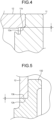
- FIG. 4 is an enlarged view of the region R 1 illustrated in FIG. 3 .
- FIG. 5 is an enlarged view of the region R 2 illustrated in FIG. 3 .
- the connection surfaces are in pressure contact with each other at each connection portion without a gap.
- the connection surface 11b of the bottom 11 and the connection surface 12a of the shell 12 are in close contact with each other without a gap.
- the connection surface 12b of the shell 12 and the connection surface 13b of the port 13 are in close contact with each other without a gap.
- the members can be stably conveyed to the welding position without detachment of the connection portion of the members even though the members are conveyed in the assembled state.
- the central axis N 11 (see FIG. 2 ) of the hole 11a of the bottom 11, the central axis N 12 of the shell 12, and the central axis N 13 of the hole 13a of the port 13 coincide with the axis N.
- the central axes may be shifted with respect to the axis N depending on the formation position of the holes.
- the members are joined to each other by welding the connection portions from the outside of the assembled exterior body (joining step).
- the welded portion C 1 formed of a region including a part of the connection portion between the bottom 11 and the shell 12, the region being melted and solidified, is formed in the bottom 11 and the shell 12 (see FIG. 1 ).
- the welded portion C 2 formed of a region including a connection portion between the shell 12 and the port 13, the region being melted and solidified, is formed in the shell 12 and the port 13.
- the connection surfaces of the respective members positioned outside the welded portions are in a state of being in pressure contact with each other, and a gap between them is zero.
- electron beam welding for example, electron beam welding, tungsten inert gas (TIG) welding, CO 2 welding, and laser welding are used, and in particular, electron beam welding is suitable.
- TIG tungsten inert gas
- CO 2 welding CO 2 welding
- laser welding laser welding
- the port 13 is press fitted into the shell 12 and welded. Thereafter, the bottom 11 and the bellows 14, and the cap bellows assembly 100 and the bellows 14 are welded, and the bottom 11 is press fitted into the shell 12 and welded.
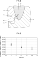
- FIG. 6 is a view schematically illustrating a section of a welded portion when a distance between members is zero.
- FIG. 7 is a view schematically illustrating a section of a welded portion when a distance between members is 0.2 mm.
- FIG. 8 is a view schematically illustrating a section of a welded portion when a distance between members is 0.4 mm.
- FIGS. 6 to 8 illustrate a gap between the connection surface 11b of the bottom 11 and the connection surface 12a of the shell 12.
- connection portion when the connection portion is not in pressure contact or a gap is generated, the interval between the connection portions is maintained even after the formation of the welded portion C 1 . Further, as illustrated in FIGS. 7 and 8 , it can be seen that when there is a gap, an intermittent portion (intermittent portions I 1 and I 2 ) corresponding to the gap is also formed at the welded portion C 1 .
- FIG. 9 is a view illustrating a relationship between an interval (gap) of connection portions and the number of times of durability.
- the hydraulic pressure was varied within a range of 0.9 to 23.1 MPa with respect to the exterior body, the pressure variation due to the hydraulic pressure was repeated until the exterior body was broken, and the number of repetitions immediately before breaking was defined as the number of times of durability.
- the hydraulic pressure was varied within a range of 0.9 to 23.1 MPa with respect to the exterior body, the pressure variation due to the hydraulic pressure was repeated until the exterior body was broken, and the number of repetitions immediately before breaking was defined as the number of times of durability.
- the number of times of durability of a sample in which the gap between the connection surface 11b of the bottom 11 and the connection surface 12a of the shell 12 is 0 is plotted by O
- the number of times of durability of the sample in which the gap is 0.2 mm is plotted by ⁇
- the number of times of durability of the sample in which the gap is 0.4 mm is plotted by ⁇ .
- the materials used and welding conditions are the same.
- the smaller the gap the larger the number of times of durability. It is considered that by press fitting the members to reduce the gap, the stress expansion coefficient of the fatigue-weakest portion decreases, and the durability improves.
- connection portion between the shell 12 and the port 13 in the same manner as at the connection portion between the bottom 11 and the shell 12, when a gap is formed at the connection portion at the time of press fitting, the fatigue strength at the joint portion between the shell 12 and the port 13 after welding may decrease.
- no gap is formed because of press fitting as in the present embodiment, it is possible to suppress a decrease in fatigue strength at the joint portion between the shell 12 and the port 13.
- the members constituting the exterior body are connected to each other through press fitting and then fixed through welding.
- the accumulator it is possible to suppress detachment of the connection portions at the time of conveyance and a decrease in fatigue strength of the exterior body.
- the present invention should not be limited only by the above-described embodiment.
- the port 13 since the locking portion 132 is locked to the shell 12 and the contents such as the bellows 14 are disposed at the time of assembling before welding, the port 13 is hardly detached from the shell 12. In this configuration, it is not essential to connect the port 13 to the shell 12 through press fitting. However, from the viewpoint of securing the joining strength, it is preferable to press fit the port 13 into the shell 12 for welding.
- the present invention can include various embodiments and the like not described herein, and various design changes and the like can be made without departing from the technical idea specified by the claims.
- the manufacturing method and the exterior body of the accumulator according to the present invention are suitable for suppressing detachment of the connection portion at the time of conveyance and a decrease in fatigue strength of the exterior body after joining.
Landscapes
- Engineering & Computer Science (AREA)
- Mechanical Engineering (AREA)
- Physics & Mathematics (AREA)
- Fluid Mechanics (AREA)
- General Engineering & Computer Science (AREA)
- Supply Devices, Intensifiers, Converters, And Telemotors (AREA)
- Butt Welding And Welding Of Specific Article (AREA)
- Diaphragms And Bellows (AREA)
Abstract
Description
- The present invention relates to a manufacturing method and an exterior body of an accumulator.
- In an accumulator, a bellows has conventionally been used as a fluid separation membrane or a fluid sealing membrane having airtightness and stretchability. The bellows is provided in an internal space formed by an exterior body including a bottom, a shell, and a port. The bottom, the shell, and the port are joined by welding at their respective connection portions (see, for example, Patent Literature 1).
- Patent Literature 1:
JP 2005-155785 A - The bottom, the shell, and the port are conveyed to a welding position in a state where the connecting members are connected to each other, and they are welded. At this time, there is a case where the connection portions are detached at the time of conveyance. Further, a generation of a gap in the connection portions after joining may lower the fatigue strength of the exterior body.
- The present invention has been made in view of the above, and an object of the present invention is to provide a manufacturing method capable of suppressing detachment of the connection portions during conveyance and a decrease in fatigue strength of an exterior body after joining, and an exterior body of an accumulator.
- To solve the above-described problem and achieve the object, a manufacturing method according to the present invention manufactures an exterior body of an accumulator including a bottom, a shell, and a port, and includes: press fitting the bottom into the shell; and melting and solidifying a region including a part of a connection portion which has been press fitted.
- Moreover, the above-described manufacturing method according to the present invention includes: press fitting the port into the shell; and melting and solidifying a region including a connection portion which has been press fitted.
- Moreover, in the above-described manufacturing method according to the present invention, the bottom is press fitted into the shell after a bellows is disposed in the shell, a natural length of the bellows is longer than a length of the shell in a longitudinal axis direction, and the bellows is in a compressed state in a state where the bottom is press fitted into the shell.
- Moreover, an exterior body of an accumulator according to the present invention is an accumulator including: an exterior body including a bottom, a shell, and a port; a bellows provided inside the exterior body; and a cap bellows assembly configured to seal one end of the bellows, wherein a welded portion formed by melting and solidifying a part of the bottom and the shell is formed at a connection portion between the bottom and the shell, and a connection surface of the bottom and a connection surface of the shell, which are continuous with the welded portion, are in a state of being in pressure contact with each other.
- The present invention provides an effect of suppressing detachment of the connection portions at the time of conveyance and a decrease in fatigue strength of the exterior body after joining when the accumulator is manufactured.
-
-
FIG. 1 is a sectional view illustrating a configuration of an accumulator according to an embodiment of the present invention. -
FIG. 2 is an exploded view illustrating a configuration of an exterior body of the accumulator illustrated inFIG. 1 . -
FIG. 3 is a sectional view illustrating a state in which each member constituting the exterior body illustrated inFIG. 2 is press fitted. -
FIG. 4 is an enlarged view of the region R1 illustrated inFIG. 3 . -
FIG. 5 is an enlarged view of the region R2 illustrated inFIG. 3 . -
FIG. 6 is a view schematically illustrating a section of a welded portion when a distance between members is zero. -
FIG. 7 is a view schematically illustrating a section of a welded portion when a distance between members is 0.2 mm. -
FIG. 8 is a view schematically illustrating a section of a welded portion when a distance between members is 0.4 mm. -
FIG. 9 is a view illustrating a relationship between an interval (gap) of connection portions and the number of times of durability. - Hereinafter, modes for carrying out the present invention (hereinafter, referred to as "embodiment") will be described with reference to the accompanying drawings. The drawings are schematic, and the relationship between the thickness and the width of each portion, the ratio of the thickness of each portion, and the like may be different from actual ones, and portions having different dimensional relationships and ratios may be included between the drawings.
-
FIG. 1 is a sectional view illustrating a configuration of an accumulator according to an embodiment of the present invention. Anaccumulator 1 illustrated inFIG. 1 includes abottom 11, ashell 12, aport 13, abellows 14 housed in an internal space formed by thebottom 11, theshell 12, and theport 13, acap body 15, a capelastic portion 16, and aguide bellows 17. Thebottom 11, theshell 12, and theport 13 constitute an exterior body of theaccumulator 1. Thecap body 15 and the capelastic portion 16 constitute acap bellows assembly 100. - Here, the
bottom 11 and theport 13 are formed by using, for example, a cold-working material. Theshell 12 is formed by using a hot-working material. - In the
accumulator 1, the space formed by thebottom 11, theshell 12, and theport 13 is divided by thebellows 14. Specifically, different spaces are formed between the outside and the inside of thebellows 14. The internal space of thebellows 14 communicates with the outside via ahole 11a of thebottom 11. The space outside thebellows 14 communicates with the outside via ahole 13a of theport 13.FIG. 1 illustrates an example in which the central axes of theholes accumulator 1. - The
bottom 11, theshell 12, and theport 13 are welded and fixed at respective connection portions. Specifically, a welded portion C1 joining thebottom 11 and theshell 12 is formed at a connection portion between thebottom 11 and theshell 12. A welded portion C2 joining theshell 12 and theport 13 is formed at a connection portion between theshell 12 and theport 13. The welded portion is formed of a part of two members to be connected, the part being melted, mixed, and then solidified. - In the
accumulator 1, a liquid (hydraulic oil) or a gas (for example, nitrogen gas) is sealed in each of a space (bellows external space) formed by the exterior body and thebellows 14 and the internal space of thebellows 14. For example, a liquid is introduced into the bellows external space, and a gas is enclosed in the internal space. - The
port 13 extends in a tubular shape and includes anintroduction portion 131 which is an introduction port of a liquid into theshell 12, and alocking portion 132 which is connected to one end of theintroduction portion 131 and is locked to an inner wall surface of theshell 12. - The
bellows 14 has a tubular shape. A side surface portion of thebellows 14 has an accordion shape formed by repeating an uneven shape, and it extends and contracts with an external load. In thebellows 14, the gap between theshell 12 and thebellows 14 is maintained by aguide bellows 17 provided on the outer peripheral side, and the bellows can smoothly extend and contract. The length of the longitudinal axis of thebellows 14 in a state where a load other than gravity is not applied (natural state) is longer than the length of theshell 12 in a longitudinal axis direction. Here, the longitudinal axis of each member coincides with the central axis N inFIG. 1 . Thebellows 14 is formed by using, for example, stainless steel (SUS304). Theguide bellows 17 is formed by using polybutylene terephthalate (PBT) or polyamide, for example. It is also possible to use a bellows having a length equal to or shorter than the length of theshell 12 in the longitudinal axis direction in the natural state. - The
cap body 15 has a plate shape and covers an opening of thebellows 14 on a side opposite to thebottom 11 side, and an end portion of thebellows 14 is welded to seal the opening. Thecap body 15 is constituted by using a material having durability to a pressure state (low pressure or high pressure) in theaccumulator 1. Thecap body 15 is formed by using, for example, metal, specifically, a steel plate hot commercial (SPHC). Thecap body 15 preferably has heat resistance according to a use state. - The cap
elastic portion 16 has a plate shape and is provided on the side of thecap body 15 opposite to thebellows 14 side. The capelastic portion 16 is positioned between theport 13 and thecap body 15, and it seals the liquid (hydraulic oil) between theshell 12 and thebellows 14. The capelastic portion 16 is formed by using, for example, acrylonitrile butadiene rubber (NBR). - In the
accumulator 1, when the pressure of the line connected to theaccumulator 1 changes through supplying/sucking the liquid via thehole 13a of theport 13, the hydraulic oil flows in from thehole 13a of theport 13, and the cap bellowsassembly 100 is pushed up. The pressure in the space between thebellows 14 and theshell 12 is always the same as the pressure inside the bellows 14. - Next, a method for manufacturing the exterior body (the bottom 11, the
shell 12, and the port 13) of theaccumulator 1 will be described with reference toFIGS. 2 to 5 .FIG. 2 is an exploded view illustrating a configuration of the exterior body of the accumulator illustrated inFIG. 1 . Each of the bottom 11, theshell 12, and theport 13 has a connection surface connected to a connection target. Specifically, the bottom 11 has aconnection surface 11b connected to theshell 12. Theshell 12 has aconnection surface 12a connected to the bottom 11 and aconnection surface 12b connected to theport 13. Theport 13 has aconnection surface 13b connected to theshell 12. From the viewpoint of suppressing the generation of abrasion powder, it is preferable that the bottom 11 and theport 13 have chamfered ends on the insertion side (see, for example,FIG. 4 ). In theshell 12, it is also preferable that an insertion side end of the bottom 11 of theconnection surface 12a is chamfered. - Here, each of the connection surfaces 11b and 13b corresponds to a columnar outer surface. Each of the connection surfaces 12a and 12b has a hole shape in which an opening forms a circle. The diameter (diameter d1) of the circle formed by the
connection surface 11b is larger than the diameter (diameter d2) of the circle formed by the opening of theconnection surface 12a. The diameter (diameter d4) of the circle formed by theconnection surface 13b is larger than the diameter (diameter d3) of the circle formed by the opening of theconnection surface 12b. The diameters d1 and d4 have values with which they can be press fitted into the diameters d2 and d3 (openings), respectively. - First, the connection surfaces of the bottom 11, the
shell 12, and theport 13 are connected. At this time, the bottom 11 and theport 13 are press fitted into the shell 12 (press-fitting step). At this time, theport 13 is inserted from the opening on theconnection surface 12a side of theshell 12, and the connection surfaces 12b and 13b are brought into close contact with each other. Thereafter, the contents such as thebellows 14 are disposed, and then theconnection surface 11b of the bottom 11 is brought into close contact with theconnection surface 12a. At this time, thebellows 14 is compressed in the exterior body. -
FIG. 3 is a sectional view illustrating a state in which each member constituting the exterior body illustrated inFIG. 2 is press fitted.FIG. 4 is an enlarged view of the region R1 illustrated inFIG. 3 .FIG. 5 is an enlarged view of the region R2 illustrated inFIG. 3 . In a state where the bottom 11 and theport 13 are press fitted into theshell 12, the connection surfaces are in pressure contact with each other at each connection portion without a gap. For example, theconnection surface 11b of the bottom 11 and theconnection surface 12a of theshell 12 are in close contact with each other without a gap. Theconnection surface 12b of theshell 12 and theconnection surface 13b of theport 13 are in close contact with each other without a gap. Thus, the members can be stably conveyed to the welding position without detachment of the connection portion of the members even though the members are conveyed in the assembled state. - At this time, the central axis N11 (see
FIG. 2 ) of thehole 11a of the bottom 11, the central axis N12 of theshell 12, and the central axis N13 of thehole 13a of theport 13 coincide with the axis N. The central axes may be shifted with respect to the axis N depending on the formation position of the holes. - Thereafter, the members are joined to each other by welding the connection portions from the outside of the assembled exterior body (joining step). For example, the welded portion C1 formed of a region including a part of the connection portion between the bottom 11 and the
shell 12, the region being melted and solidified, is formed in the bottom 11 and the shell 12 (seeFIG. 1 ). The welded portion C2 formed of a region including a connection portion between theshell 12 and theport 13, the region being melted and solidified, is formed in theshell 12 and theport 13. At this time, because the regions melt at the time of welding, contamination after welding is suppressed even though abrasion powder or the like is generated at the time of press fitting. The connection surfaces of the respective members positioned outside the welded portions are in a state of being in pressure contact with each other, and a gap between them is zero. - As the welding process, for example, electron beam welding, tungsten inert gas (TIG) welding, CO2 welding, and laser welding are used, and in particular, electron beam welding is suitable.
- In the manufacturing of the accumulator, for example, the
port 13 is press fitted into theshell 12 and welded. Thereafter, the bottom 11 and thebellows 14, and the cap bellowsassembly 100 and thebellows 14 are welded, and the bottom 11 is press fitted into theshell 12 and welded. - Here, a welding mode based on the interval between the connection portions will be described with reference to
FIGS. 6 to 8 .FIG. 6 is a view schematically illustrating a section of a welded portion when a distance between members is zero.FIG. 7 is a view schematically illustrating a section of a welded portion when a distance between members is 0.2 mm.FIG. 8 is a view schematically illustrating a section of a welded portion when a distance between members is 0.4 mm.FIGS. 6 to 8 illustrate a gap between theconnection surface 11b of the bottom 11 and theconnection surface 12a of theshell 12. - As illustrated in
FIGS. 6 to 8 , when the connection portion is not in pressure contact or a gap is generated, the interval between the connection portions is maintained even after the formation of the welded portion C1. Further, as illustrated inFIGS. 7 and8 , it can be seen that when there is a gap, an intermittent portion (intermittent portions I1 and I2) corresponding to the gap is also formed at the welded portion C1. - Next, the relationship between the distance between the connection portions and the number of times of durability in a durability test of the exterior body will be described with reference to
FIG. 9. FIG. 9 is a view illustrating a relationship between an interval (gap) of connection portions and the number of times of durability. In the durability test, the hydraulic pressure was varied within a range of 0.9 to 23.1 MPa with respect to the exterior body, the pressure variation due to the hydraulic pressure was repeated until the exterior body was broken, and the number of repetitions immediately before breaking was defined as the number of times of durability. InFIG. 9 , the number of times of durability of a sample in which the gap between theconnection surface 11b of the bottom 11 and theconnection surface 12a of theshell 12 is 0 is plotted by O, the number of times of durability of the sample in which the gap is 0.2 mm is plotted by △, and the number of times of durability of the sample in which the gap is 0.4 mm is plotted by □. The materials used and welding conditions are the same. As can be seen fromFIG. 9 , the smaller the gap, the larger the number of times of durability. It is considered that by press fitting the members to reduce the gap, the stress expansion coefficient of the fatigue-weakest portion decreases, and the durability improves. - Also, at the connection portion between the
shell 12 and theport 13, in the same manner as at the connection portion between the bottom 11 and theshell 12, when a gap is formed at the connection portion at the time of press fitting, the fatigue strength at the joint portion between theshell 12 and theport 13 after welding may decrease. On the other hand, when no gap is formed because of press fitting as in the present embodiment, it is possible to suppress a decrease in fatigue strength at the joint portion between theshell 12 and theport 13. - According to the present embodiment, at the time of manufacturing the exterior body, the members constituting the exterior body are connected to each other through press fitting and then fixed through welding. Thus, at the time of manufacturing the accumulator, it is possible to suppress detachment of the connection portions at the time of conveyance and a decrease in fatigue strength of the exterior body.
- In addition, according to the present embodiment, since a state in which there is no gap at the connection portion is maintained even after the members constituting the exterior body are welded to each other, high durability against repeated use can be obtained.
- In addition, according to the present embodiment, even when the bellows 14 is compressed and stored in the exterior body when the connection surfaces of the bottom 11, the
shell 12, and theport 13 are connected (press fitted), since the connection portions are press fitted, the bottom 11 is not detached by the reaction force of the bellows, and conveyance or welding processing can be performed safely. - Although an embodiment for carrying out the present invention have been described so far, the present invention should not be limited only by the above-described embodiment. Here, in the
port 13, since the lockingportion 132 is locked to theshell 12 and the contents such as thebellows 14 are disposed at the time of assembling before welding, theport 13 is hardly detached from theshell 12. In this configuration, it is not essential to connect theport 13 to theshell 12 through press fitting. However, from the viewpoint of securing the joining strength, it is preferable to press fit theport 13 into theshell 12 for welding. - As described here, the present invention can include various embodiments and the like not described herein, and various design changes and the like can be made without departing from the technical idea specified by the claims.
- As described above, the manufacturing method and the exterior body of the accumulator according to the present invention are suitable for suppressing detachment of the connection portion at the time of conveyance and a decrease in fatigue strength of the exterior body after joining.
-
- 1 ACCUMULATOR
- 11 BOTTOM
- 11a, 13a HOLE
- 11b, 12a, 12b, 13b CONNECTION SURFACE
- 12 SHELL
- 13 PORT
- 14 BELLOWS
- 15 CAP BODY
- 16 CAP ELASTIC PORTION
- 17 GUIDE BELLOWS
- 100 CAP BELLOWS ASSEMBLY
- 131 INTRODUCTION PORTION
- 132 LOCKING PORTION
- C1, C2 WELDED PORTION
Claims (4)
- A manufacturing method for manufacturing an exterior body of an accumulator including a bottom, a shell, and a port, the method comprising:press fitting the bottom into the shell; andmelting and solidifying a region including a part of a connection portion which has been press fitted.
- The manufacturing method according to claim 1, comprising:press fitting the port into the shell; andmelting and solidifying a region including a connection portion which has been press fitted.
- The manufacturing method according to claim 1 or 2, whereinthe bottom is press fitted into the shell after a bellows is disposed in the shell,a natural length of the bellows is longer than a length of the shell in a longitudinal axis direction, andthe bellows is in a compressed state in a state where the bottom is press fitted into the shell.
- An exterior body of an accumulator, the accumulator comprising:an exterior body including a bottom, a shell, and a port;a bellows provided inside the exterior body; anda cap bellows assembly configured to seal one end of the bellows, whereina welded portion formed by melting and solidifying a part of the bottom and the shell is formed at a connection portion between the bottom and the shell, anda connection surface of the bottom and a connection surface of the shell, which are continuous with the welded portion, are in a state of being in pressure contact with each other.
Applications Claiming Priority (2)
| Application Number | Priority Date | Filing Date | Title |
|---|---|---|---|
| JP2022004005A JP2023103129A (en) | 2022-01-13 | 2022-01-13 | Manufacturing method and outer body of accumulator |
| PCT/JP2023/000222 WO2023136223A1 (en) | 2022-01-13 | 2023-01-06 | Manufacturing method and accumulator exterior body |
Publications (2)
| Publication Number | Publication Date |
|---|---|
| EP4464900A1 true EP4464900A1 (en) | 2024-11-20 |
| EP4464900A4 EP4464900A4 (en) | 2025-05-21 |
Family
ID=87279083
Family Applications (1)
| Application Number | Title | Priority Date | Filing Date |
|---|---|---|---|
| EP23740232.6A Pending EP4464900A4 (en) | 2022-01-13 | 2023-01-06 | Manufacturing method and accumulator exterior body |
Country Status (5)
| Country | Link |
|---|---|
| US (1) | US20250067282A1 (en) |
| EP (1) | EP4464900A4 (en) |
| JP (1) | JP2023103129A (en) |
| CN (1) | CN118434977A (en) |
| WO (1) | WO2023136223A1 (en) |
Family Cites Families (7)
| Publication number | Priority date | Publication date | Assignee | Title |
|---|---|---|---|---|
| JPH0564502U (en) * | 1992-02-10 | 1993-08-27 | 東海ゴム工業株式会社 | accumulator |
| DE4436882C2 (en) * | 1994-10-15 | 1996-11-14 | Sima Tec Singer Mayr Gmbh | Sheet metal component with load-bearing function |
| JP3333649B2 (en) * | 1994-10-21 | 2002-10-15 | エヌオーケー株式会社 | accumulator |
| JP3818353B2 (en) * | 1998-09-29 | 2006-09-06 | Nok株式会社 | accumulator |
| JP2002039102A (en) * | 2000-07-19 | 2002-02-06 | Nhk Spring Co Ltd | accumulator |
| JP2005155785A (en) | 2003-11-26 | 2005-06-16 | Nok Corp | Accumulator |
| JP6803271B2 (en) * | 2017-03-13 | 2020-12-23 | 日本発條株式会社 | accumulator |
-
2022
- 2022-01-13 JP JP2022004005A patent/JP2023103129A/en active Pending
-
2023
- 2023-01-06 CN CN202380015428.0A patent/CN118434977A/en active Pending
- 2023-01-06 US US18/724,700 patent/US20250067282A1/en active Pending
- 2023-01-06 WO PCT/JP2023/000222 patent/WO2023136223A1/en not_active Ceased
- 2023-01-06 EP EP23740232.6A patent/EP4464900A4/en active Pending
Also Published As
| Publication number | Publication date |
|---|---|
| CN118434977A (en) | 2024-08-02 |
| JP2023103129A (en) | 2023-07-26 |
| WO2023136223A1 (en) | 2023-07-20 |
| US20250067282A1 (en) | 2025-02-27 |
| EP4464900A4 (en) | 2025-05-21 |
Similar Documents
| Publication | Publication Date | Title |
|---|---|---|
| US8282305B2 (en) | Ball sleeve joint and process for manufacturing same | |
| US20220181833A1 (en) | Connector housings, use of, and method therefor | |
| JP5695796B2 (en) | Corrosion resistant isolator assembly for process equipment | |
| US8205713B2 (en) | Vehicle silencer | |
| KR101540949B1 (en) | Piston assembly, fluid pressure cylinder, method for manufacturing piston assembly | |
| CN103026801B (en) | The port part of cavity is accelerated in superconduction | |
| US9539670B2 (en) | Joint for tubular materials | |
| CN105402106A (en) | Compressor And Method For Manufacturing Compressor | |
| US20130228980A1 (en) | Resilient seal having a pressurized bellows spring | |
| EP3298262B1 (en) | Reinforced end cap assembly for pressure vessel | |
| US20250067282A1 (en) | Manufacturing method and exterior body of accumulator | |
| JPH063331B2 (en) | Sealed container | |
| CN205013244U (en) | compressor | |
| JP4039937B2 (en) | Connection structure of branch connector in fuel pressure accumulator | |
| EP2519758B1 (en) | End member assembly, gas spring assembly and method | |
| EP1602870A1 (en) | Tube to hose coupling | |
| US20250215905A1 (en) | Accumulator | |
| EP3769063B1 (en) | Measuring element and measuring device comprising the same | |
| WO1996005493A1 (en) | Explosion welded transition joint for a pressure transmitter | |
| JP4586516B2 (en) | Joining structure of metal flexible tube and connecting joint | |
| EP3121500B1 (en) | Coupling for fixedly and sealingly securing components to one another with improved sealing | |
| RU2181858C1 (en) | High-pressure bottle and method of its manufacture from tube | |
| JP4378329B2 (en) | Connection structure between integrated panel and fluidic device | |
| US20250043890A1 (en) | Swage fitting for tubing connections and method | |
| KR102592097B1 (en) | Combination structure of components of susceptor for semiconductor by friction diffusion welding and chamber and combination method thereof |
Legal Events
| Date | Code | Title | Description |
|---|---|---|---|
| STAA | Information on the status of an ep patent application or granted ep patent |
Free format text: STATUS: THE INTERNATIONAL PUBLICATION HAS BEEN MADE |
|
| PUAI | Public reference made under article 153(3) epc to a published international application that has entered the european phase |
Free format text: ORIGINAL CODE: 0009012 |
|
| STAA | Information on the status of an ep patent application or granted ep patent |
Free format text: STATUS: REQUEST FOR EXAMINATION WAS MADE |
|
| 17P | Request for examination filed |
Effective date: 20240709 |
|
| AK | Designated contracting states |
Kind code of ref document: A1 Designated state(s): AL AT BE BG CH CY CZ DE DK EE ES FI FR GB GR HR HU IE IS IT LI LT LU LV MC ME MK MT NL NO PL PT RO RS SE SI SK SM TR |
|
| DAV | Request for validation of the european patent (deleted) | ||
| DAX | Request for extension of the european patent (deleted) | ||
| A4 | Supplementary search report drawn up and despatched |
Effective date: 20250424 |
|
| RIC1 | Information provided on ipc code assigned before grant |
Ipc: F15B 1/10 20060101ALI20250416BHEP Ipc: B23P 15/00 20060101ALI20250416BHEP Ipc: B23P 11/00 20060101ALI20250416BHEP Ipc: B23K 9/00 20060101ALI20250416BHEP Ipc: F15B 1/16 20060101AFI20250416BHEP |