EP4464898A1 - Draw-through fan assembly and heat exchanger system - Google Patents
Draw-through fan assembly and heat exchanger system Download PDFInfo
- Publication number
- EP4464898A1 EP4464898A1 EP24176738.3A EP24176738A EP4464898A1 EP 4464898 A1 EP4464898 A1 EP 4464898A1 EP 24176738 A EP24176738 A EP 24176738A EP 4464898 A1 EP4464898 A1 EP 4464898A1
- Authority
- EP
- European Patent Office
- Prior art keywords
- fan
- heat exchanger
- fan assembly
- bell mouth
- exchanger system
- Prior art date
- Legal status (The legal status is an assumption and is not a legal conclusion. Google has not performed a legal analysis and makes no representation as to the accuracy of the status listed.)
- Pending
Links
- 238000011144 upstream manufacturing Methods 0.000 claims abstract description 18
- 239000000463 material Substances 0.000 claims description 4
- XLYOFNOQVPJJNP-UHFFFAOYSA-N water Substances O XLYOFNOQVPJJNP-UHFFFAOYSA-N 0.000 claims description 4
- 229910000831 Steel Inorganic materials 0.000 claims description 3
- 239000010959 steel Substances 0.000 claims description 3
- 238000001816 cooling Methods 0.000 description 12
- 238000010586 diagram Methods 0.000 description 4
- 238000012986 modification Methods 0.000 description 2
- 230000004048 modification Effects 0.000 description 2
- 238000004378 air conditioning Methods 0.000 description 1
- 230000003466 anti-cipated effect Effects 0.000 description 1
- 230000007423 decrease Effects 0.000 description 1
- 230000003247 decreasing effect Effects 0.000 description 1
- 230000010354 integration Effects 0.000 description 1
- 230000003993 interaction Effects 0.000 description 1
- 239000002184 metal Substances 0.000 description 1
- 229910052751 metal Inorganic materials 0.000 description 1
- 229910001092 metal group alloy Inorganic materials 0.000 description 1
- 238000000034 method Methods 0.000 description 1
- QQONPFPTGQHPMA-UHFFFAOYSA-N propylene Natural products CC=C QQONPFPTGQHPMA-UHFFFAOYSA-N 0.000 description 1
- 125000004805 propylene group Chemical group [H]C([H])([H])C([H])([*:1])C([H])([H])[*:2] 0.000 description 1
Images




Classifications
-
- F—MECHANICAL ENGINEERING; LIGHTING; HEATING; WEAPONS; BLASTING
- F24—HEATING; RANGES; VENTILATING
- F24F—AIR-CONDITIONING; AIR-HUMIDIFICATION; VENTILATION; USE OF AIR CURRENTS FOR SCREENING
- F24F1/00—Room units for air-conditioning, e.g. separate or self-contained units or units receiving primary air from a central station
- F24F1/0007—Indoor units, e.g. fan coil units
- F24F1/0018—Indoor units, e.g. fan coil units characterised by fans
- F24F1/0029—Axial fans
-
- F—MECHANICAL ENGINEERING; LIGHTING; HEATING; WEAPONS; BLASTING
- F04—POSITIVE - DISPLACEMENT MACHINES FOR LIQUIDS; PUMPS FOR LIQUIDS OR ELASTIC FLUIDS
- F04D—NON-POSITIVE-DISPLACEMENT PUMPS
- F04D19/00—Axial-flow pumps
- F04D19/002—Axial flow fans
-
- F—MECHANICAL ENGINEERING; LIGHTING; HEATING; WEAPONS; BLASTING
- F04—POSITIVE - DISPLACEMENT MACHINES FOR LIQUIDS; PUMPS FOR LIQUIDS OR ELASTIC FLUIDS
- F04D—NON-POSITIVE-DISPLACEMENT PUMPS
- F04D29/00—Details, component parts, or accessories
- F04D29/08—Sealings
- F04D29/16—Sealings between pressure and suction sides
- F04D29/161—Sealings between pressure and suction sides especially adapted for elastic fluid pumps
- F04D29/164—Sealings between pressure and suction sides especially adapted for elastic fluid pumps of an axial flow wheel
-
- F—MECHANICAL ENGINEERING; LIGHTING; HEATING; WEAPONS; BLASTING
- F04—POSITIVE - DISPLACEMENT MACHINES FOR LIQUIDS; PUMPS FOR LIQUIDS OR ELASTIC FLUIDS
- F04D—NON-POSITIVE-DISPLACEMENT PUMPS
- F04D29/00—Details, component parts, or accessories
- F04D29/26—Rotors specially for elastic fluids
- F04D29/32—Rotors specially for elastic fluids for axial flow pumps
- F04D29/325—Rotors specially for elastic fluids for axial flow pumps for axial flow fans
- F04D29/326—Rotors specially for elastic fluids for axial flow pumps for axial flow fans comprising a rotating shroud
-
- F—MECHANICAL ENGINEERING; LIGHTING; HEATING; WEAPONS; BLASTING
- F04—POSITIVE - DISPLACEMENT MACHINES FOR LIQUIDS; PUMPS FOR LIQUIDS OR ELASTIC FLUIDS
- F04D—NON-POSITIVE-DISPLACEMENT PUMPS
- F04D29/00—Details, component parts, or accessories
- F04D29/40—Casings; Connections of working fluid
- F04D29/52—Casings; Connections of working fluid for axial pumps
- F04D29/54—Fluid-guiding means, e.g. diffusers
- F04D29/541—Specially adapted for elastic fluid pumps
- F04D29/545—Ducts
-
- F—MECHANICAL ENGINEERING; LIGHTING; HEATING; WEAPONS; BLASTING
- F04—POSITIVE - DISPLACEMENT MACHINES FOR LIQUIDS; PUMPS FOR LIQUIDS OR ELASTIC FLUIDS
- F04D—NON-POSITIVE-DISPLACEMENT PUMPS
- F04D29/00—Details, component parts, or accessories
- F04D29/58—Cooling; Heating; Diminishing heat transfer
- F04D29/582—Cooling; Heating; Diminishing heat transfer specially adapted for elastic fluid pumps
-
- F—MECHANICAL ENGINEERING; LIGHTING; HEATING; WEAPONS; BLASTING
- F04—POSITIVE - DISPLACEMENT MACHINES FOR LIQUIDS; PUMPS FOR LIQUIDS OR ELASTIC FLUIDS
- F04D—NON-POSITIVE-DISPLACEMENT PUMPS
- F04D29/00—Details, component parts, or accessories
- F04D29/58—Cooling; Heating; Diminishing heat transfer
- F04D29/582—Cooling; Heating; Diminishing heat transfer specially adapted for elastic fluid pumps
- F04D29/5826—Cooling at least part of the working fluid in a heat exchanger
-
- F—MECHANICAL ENGINEERING; LIGHTING; HEATING; WEAPONS; BLASTING
- F04—POSITIVE - DISPLACEMENT MACHINES FOR LIQUIDS; PUMPS FOR LIQUIDS OR ELASTIC FLUIDS
- F04D—NON-POSITIVE-DISPLACEMENT PUMPS
- F04D29/00—Details, component parts, or accessories
- F04D29/60—Mounting; Assembling; Disassembling
- F04D29/601—Mounting; Assembling; Disassembling specially adapted for elastic fluid pumps
-
- F—MECHANICAL ENGINEERING; LIGHTING; HEATING; WEAPONS; BLASTING
- F04—POSITIVE - DISPLACEMENT MACHINES FOR LIQUIDS; PUMPS FOR LIQUIDS OR ELASTIC FLUIDS
- F04D—NON-POSITIVE-DISPLACEMENT PUMPS
- F04D29/00—Details, component parts, or accessories
- F04D29/60—Mounting; Assembling; Disassembling
- F04D29/64—Mounting; Assembling; Disassembling of axial pumps
- F04D29/644—Mounting; Assembling; Disassembling of axial pumps especially adapted for elastic fluid pumps
- F04D29/646—Mounting or removal of fans
-
- F—MECHANICAL ENGINEERING; LIGHTING; HEATING; WEAPONS; BLASTING
- F24—HEATING; RANGES; VENTILATING
- F24F—AIR-CONDITIONING; AIR-HUMIDIFICATION; VENTILATION; USE OF AIR CURRENTS FOR SCREENING
- F24F1/00—Room units for air-conditioning, e.g. separate or self-contained units or units receiving primary air from a central station
- F24F1/0007—Indoor units, e.g. fan coil units
- F24F1/0059—Indoor units, e.g. fan coil units characterised by heat exchangers
- F24F1/0063—Indoor units, e.g. fan coil units characterised by heat exchangers by the mounting or arrangement of the heat exchangers
-
- F—MECHANICAL ENGINEERING; LIGHTING; HEATING; WEAPONS; BLASTING
- F24—HEATING; RANGES; VENTILATING
- F24F—AIR-CONDITIONING; AIR-HUMIDIFICATION; VENTILATION; USE OF AIR CURRENTS FOR SCREENING
- F24F13/00—Details common to, or for air-conditioning, air-humidification, ventilation or use of air currents for screening
-
- F—MECHANICAL ENGINEERING; LIGHTING; HEATING; WEAPONS; BLASTING
- F24—HEATING; RANGES; VENTILATING
- F24F—AIR-CONDITIONING; AIR-HUMIDIFICATION; VENTILATION; USE OF AIR CURRENTS FOR SCREENING
- F24F13/00—Details common to, or for air-conditioning, air-humidification, ventilation or use of air currents for screening
- F24F13/24—Means for preventing or suppressing noise
-
- F—MECHANICAL ENGINEERING; LIGHTING; HEATING; WEAPONS; BLASTING
- F24—HEATING; RANGES; VENTILATING
- F24F—AIR-CONDITIONING; AIR-HUMIDIFICATION; VENTILATION; USE OF AIR CURRENTS FOR SCREENING
- F24F13/00—Details common to, or for air-conditioning, air-humidification, ventilation or use of air currents for screening
- F24F13/30—Arrangement or mounting of heat-exchangers
-
- F—MECHANICAL ENGINEERING; LIGHTING; HEATING; WEAPONS; BLASTING
- F28—HEAT EXCHANGE IN GENERAL
- F28D—HEAT-EXCHANGE APPARATUS, NOT PROVIDED FOR IN ANOTHER SUBCLASS, IN WHICH THE HEAT-EXCHANGE MEDIA DO NOT COME INTO DIRECT CONTACT
- F28D1/00—Heat-exchange apparatus having stationary conduit assemblies for one heat-exchange medium only, the media being in contact with different sides of the conduit wall, in which the other heat-exchange medium is a large body of fluid, e.g. domestic or motor car radiators
- F28D1/02—Heat-exchange apparatus having stationary conduit assemblies for one heat-exchange medium only, the media being in contact with different sides of the conduit wall, in which the other heat-exchange medium is a large body of fluid, e.g. domestic or motor car radiators with heat-exchange conduits immersed in the body of fluid
- F28D1/0233—Heat-exchange apparatus having stationary conduit assemblies for one heat-exchange medium only, the media being in contact with different sides of the conduit wall, in which the other heat-exchange medium is a large body of fluid, e.g. domestic or motor car radiators with heat-exchange conduits immersed in the body of fluid with air flow channels
- F28D1/024—Heat-exchange apparatus having stationary conduit assemblies for one heat-exchange medium only, the media being in contact with different sides of the conduit wall, in which the other heat-exchange medium is a large body of fluid, e.g. domestic or motor car radiators with heat-exchange conduits immersed in the body of fluid with air flow channels with an air driving element
-
- F—MECHANICAL ENGINEERING; LIGHTING; HEATING; WEAPONS; BLASTING
- F05—INDEXING SCHEMES RELATING TO ENGINES OR PUMPS IN VARIOUS SUBCLASSES OF CLASSES F01-F04
- F05D—INDEXING SCHEME FOR ASPECTS RELATING TO NON-POSITIVE-DISPLACEMENT MACHINES OR ENGINES, GAS-TURBINES OR JET-PROPULSION PLANTS
- F05D2250/00—Geometry
- F05D2250/70—Shape
- F05D2250/75—Shape given by its similarity to a letter, e.g. T-shaped
Definitions
- This invention relates to the field of cooling and air conditioning systems, and more particularly, a draw-through fan assembly and heat exchanger system configuration.
- a draw-through fan assembly and heat exchanger system comprising a fan deck adapted to mount a fan assembly.
- the fan assembly comprises an axial fan with a rotating shroud.
- a heat exchanger section (which may include one or more heat exchangers) is located upstream of the fan and the fan assembly.
- a J-shaped inlet bell mouth configured upstream of the fan deck is located within a space between (the one or more) heat exchangers.
- a motor associated with the fan assembly and one or more motor struts are positioned upstream of the fan.
- the bell mouth comprises one or more holes at the bottom to drain water collected in the bell mouth.
- the one or more holes of the bell mouth are louvered to facilitate leakage air flow turning.
- the bell mouth comprises turbulence control fences.
- the bell mouth is made of polymeric material.
- a discharge grille is positioned downstream of the fan.
- the discharge grille comprises a step diffuser having a diameter greater than the diameter of the fan.
- the discharge grille comprises air guide vanes.
- the fan is configured to discharge air vertically upward.
- the heat exchanger section comprises one or more heat exchangers configured in a V or W coil arrangement.
- a bottom curved periphery of the J-shaped bell-mouth comprises depressions complimentary to the profile of the heat exchangers.
- the one or more motor struts are U-shaped, wherein a bottom of the U-shaped strut is adapted to mount the motor, a top of the U-shaped strut attaches to the fan deck, and sides of the U-shaped strut remain in frictional contact with the bell mouth.
- the outer surface of the bell mouth comprises one or more grooves that are adapted to engage with and remain in frictional contact with the motor struts.
- each of the motor struts comprises an engaging portion on the inner side of the struts, which is adapted to engage with and remain in frictional contact with the corresponding grooves of the bell mouth.
- the motor struts are made of steel.
- Embodiments of the invention achieve this by adjusting the vertical position of the fan assembly and discharge stack, dropping them down into the space between the heat exchangers.
- Embodiments of the invention include an inlet that will be shaped to optimize airflow and noise while being coordinated with the fan motor struts to attenuate vibrations.
- the bell mouth and the fan may remain below the fan deck and are disposed of within a space between the heat exchangers.
- the cooling system may also be a part of a chiller. As a result, the overall height of the cooling system or the chiller is reduced. Alternatively, this enables the use of larger heat exchangers while maintaining the same height as existing cooling systems. This provides potential to make the cooling system or chiller more compact and/or improve its efficiency.
- embodiments of the invention are capable of absorbing vibration and of the fan and motor subsystem.
- FIGs. 1 and 2 an exemplary embodiment of the draw-through fan assembly 200 (also referred to as fan assembly, herein) fitted in a configuration 100 comprising a fan deck 102, a bell mouth 104, and motor struts 106 is disclosed.
- the fan assembly 200 includes an axial shrouded fan 202 that is positioned upstream of the fan deck 102 forming a draw-through fan configuration that discharges air vertically upward.
- the fan assembly 200 includes the shrouded fan 202 concentrically mounted within the configuration 100 (fan deck 102, bell mouth 104, and motor struts 106).
- the fan deck 102 has a flat profile with an opening, which is adapted to be fitted at the outlet of the heat exchanger section.
- the heat exchanger section may include one or more heat exchangers 302 that may be a flat, curved, Y-shaped, Z-shaped or of any other shape, which may be arranged vertically or obliquely or in any other orientation to form arrangements including but not limited to V or W coil arrangements.
- the fan deck 102 has a dimension based on the outlet of the heat exchanger section 302. An upstream of the fan deck 102 corresponds to the bottom side of the fan deck 102 that is facing the heat exchanger 302 and downstream (opposite to the upstream) of the fan deck 102 corresponds to the top side that is above the fan deck 102.
- the bell mouth 104 has a J-shape contour inserted or fitted upstream of the fan deck 102.
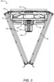
- the bell mouth 104 can have a profile and dimension based on a space 304 between the heat exchangers 302, such that once the fan assembly 200 is fitted at the outlet of the heat exchangers 302, the bell mouth 104 and shrouded fan 202 remains below the fan deck 102 and in the space 304 between the heat exchangers 302 as shown in FIG. 3 .
- the motor struts 106 have a substantially U-shaped profile configured upstream of the bell mouth 104 and the fan deck 102 such that the struts 106 extend along an outer surface of the bell mouth 104, from the bottom end to the top end of the bell mouth 104 and further extending substantially parallel to the bottom surface of the fan deck 102, wherein the top end of the struts 106 are attached to the bottom surface of the fan deck 102, and at least a portion of the inner side of the struts 106 remain in frictional contact with an outer surface of the bell mouth 104.
- the bell mouth 104 and the mounted shrouded fan 202 remain below the fan deck 102 and are disposed within the space 304 between the heat exchangers 302 in the cooling system 300 as shown in FIG. 3
- the fan assembly 200 is adapted to be configured with various types of heat exchangers having different coil arrangements such as but not limited to "U','V', or "W" shapes.
- the profile and dimension of the bell mouth 104 can be chosen based on the coil arrangement of the heat exchanger. For instance, in the case of a V-shaped coil arrangement (as shown in FIG. 3 ), the bell mouth is J-shaped where the diameter of the bell mouth 104 decreases from the top end (i.e, at the rim of the fan deck 102) toward the bottom end, which allows the bell mouth 104 to be positioned in the space 304 between the heat exchangers 302. Referring to FIGs.
- the bell mouth 104 includes an outer section 104-1 having its diameter decreasing from the top end to the bottom end and having a first predefined height based on the height of the fan 202 to be mounted such that the fan 202 remains within the bell mouth 104.
- the bell mouth 104 further includes a vertical inner section 104-2 having a diameter less than the diameter of the bottom end of the outer section 104-1.
- the inner section 104-2 has a second predefined height much shorter than the first predefined height of the outer section 104-1 of the bell mouth 104,
- the inner section 104-2 remains connected to the bottom end of the outer section 104-1 by a curved section 104-3 at the bottom of the bell mouth 104, thereby forming the bell mouth having the J-shaped contour or profile.
- the dimension and shape of the fan deck 102 can be chosen to fit at the outlet of the heat exchanger 302.
- the fan deck 102 is square or rectangular-shaped.
- the rim of the opening of the fan deck 102 can have shortened inclined or curved extension 102-1 protruding on the inlet side (bottom) of the fan deck 102 for stiffness.
- the bell mouth 104 can be removably inserted within the opening of the fan deck 102 such that the rim of the fan deck 102 engages and locks with the top end of the bell mouth 104 and the bottom of the bell mouth 104 remains below the fan deck 102.
- the bell mouth 104 can be an integral part of the fan deck 102 to form the casing, wherein the bell mouth 104 protrudes in a downward direction from the rim of the opening of the fan deck 102.
- the strut 106 can have a predefined profile based on a profile of the outer surface of the bell mouth 104 such that the struts 106 extend axially along the outer surface of the bell mouth 104, and further extending substantially parallel to the bottom surface of the fan deck 102.
- the struts 106 can have a substantially U-shaped profile, extending on opposite sides along the outer surface of the bell mouth 104 up to the bottom surface of the fan deck 102.
- the top end of the U-shaped strut 106 can be substantially parallel to the bottom surface of the fan deck 102.
- the inner side of each U-shaped strut 106 includes an engaging portion 108 that extends perpendicular to the flat surface of the struts 106.
- the outer surface of the bell mouth 104 includes grooves 110 at predefined positions.
- the engaging portion 108 can have a profile concurrent to a profile of the grooves 110 on the bell mouth 104.
- the engaging portion 108 of the struts 106 are adapted to remain engaged and in frictional contact with one of the grooves 110 of the bell mouth 104.
- the bottom of the U-shaped struts 106 have mounting elements 112 at the bottom to mount the motor 204.
- the outer surface of the bell mouth 104 includes depressions 114 concurrent to a profile of the heat exchangers 302 to provide clearance and facilitate the integration of the bell mouth 104 and the fan 202 below the fan deck 102, within the space 304 between the heat exchangers 302.
- the depressions 114 allow clearance between the fan assembly 100 and the heat exchanger 302.
- the depressions 114 can be provided at the bottom curved periphery (curved section 104-3) of the bell mouth 104 and/or at other areas of the outer surface of the bell mouth 104 as required.
- the bell mouth 104 and shrouded fan 202 remain below the fan deck 102 and are disposed of within the space 304 between the heat exchangers 302.
- the overall height of the cooling system 300 in this invention remains less than that of the existing cooling systems, which enables the use of larger heat exchangers 302 while maintaining the same height of the overall cooling system 300. This provides significant potential to keep the cooling system 300 compact and/or improve its efficiency
- the bell mouth 104 is made of a polymeric material such as propylene and the struts 106 are made of a metal or metal alloy such as steel.
- the system is capable of absorbing vibration and attenuating noise generated by the shrouded fan 202 and motor.
- the shrouded fan 202 includes a plurality of fan blades 210 extending from the rotor hub 206 about a central axis of the fan 202 and terminating at a fan shroud 212.
- the fan shroud 212 extends circumferentially around a central axis of the fan 202 and is secured to the plurality of fan blades 210 and also rotates about the fan axis therewith.
- the fan shroud 212 comprises an S-shaped curve located on the upstream end of the shroud, in which the outer diameter of the S-shaped curve has a diameter larger than the inner diameter of bell mouth 104.
- the fan 202 further includes a stator assembly including a plurality of stator vanes, located downstream of the fan rotor.
- the hub 206 of the fan 202 is mounted on the motor 204 located at the bottom of the U-shaped struts 106. Blades 210, stator vanes, and rotor hub remain within the bell mouth 104.
- the bell mouth 104 includes one or more louvered water drain holes 402, at the bottom of the bell mouth 104.
- the louvered profile of the drain holes 402 facilitates leakage airflow turning and interaction towards an inlet of the bell mouth 104.
- the bell mouth 104 includes turbulence control fences 602 to reduce air turbulence at the inlet of the fan 202 and further reduce fan noise.
- the fan assembly further includes discharge grille 216 as shown in FIG. 5 , which has a circular profile configured downstream of the opening of the fan deck 102.
- the discharge grille 216 can be specially designed to shorten its height, such that a minimal part or no part of the discharge grille 216 remains above the fan deck 102.
- the discharge grille 216 allows air to flow out of the fan assembly or heat exchanger and restricts outside objects from falling into the fan assembly or heat exchanger.
- the discharge grille includes a stepped diffuser 214 having a diameter greater than the diameter of the rotating fan shroud 212 but less than the diameter of the bell mouth 104 such that the diffuser wall 214 extends from the bottom of the fan deck 102 up to a predefined depth in a downward direction within the bell mouth 104, thereby forming a step diffuser configuration.
- embodiments of the invention enable the use of larger heat exchangers without increasing the overall height of the cooling system, by adjusting the vertical position of the fan assembly and discharge stack, dropping them down into the empty space between the heat exchangers and allowing the addition of coil length while maintaining an equivalent box size and restricting vibration forces and attenuate noise generated by the fan and motor.
Landscapes
- Engineering & Computer Science (AREA)
- Mechanical Engineering (AREA)
- General Engineering & Computer Science (AREA)
- Chemical & Material Sciences (AREA)
- Combustion & Propulsion (AREA)
- Physics & Mathematics (AREA)
- Thermal Sciences (AREA)
- Other Air-Conditioning Systems (AREA)
- Structures Of Non-Positive Displacement Pumps (AREA)
Abstract
A draw-through fan assembly and heat exchanger system configuration is disclosed, comprising a fan deck (102) adapted to mount the fan assembly (200), an axial fan (202) with a rotating shroud (212), a heat exchanger section located upstream of the fan (202) and the fan assembly (200), and a J-shaped inlet bell mouth (104) configured upstream of the fan deck (102) that is located within a space (304) between heat exchangers (302). Further, a motor (204) associated with the fan assembly (200) and one or more motor struts (106) are positioned upstream of the fan (202). The fan (202) is mounted on the bottom of the struts (106), such that once the fan-mounted assembly is configured at the outlet of the heat exchangers (302), the bell mouth (104) and fan (202) remain below the fan deck (102) and are disposed in a space (304) between the heat exchangers (302).
Description
- This patent application claims the benefit of
US Provisional Patent Application No. 63/503,371, filed on May 19, 2023 - This invention relates to the field of cooling and air conditioning systems, and more particularly, a draw-through fan assembly and heat exchanger system configuration.
- According to a first aspect of the invention there is provided a draw-through fan assembly and heat exchanger system comprising a fan deck adapted to mount a fan assembly. The fan assembly comprises an axial fan with a rotating shroud. A heat exchanger section (which may include one or more heat exchangers) is located upstream of the fan and the fan assembly. A J-shaped inlet bell mouth configured upstream of the fan deck is located within a space between (the one or more) heat exchangers. A motor associated with the fan assembly and one or more motor struts are positioned upstream of the fan.
- Optionally, the bell mouth comprises one or more holes at the bottom to drain water collected in the bell mouth.
- Optionally, the one or more holes of the bell mouth are louvered to facilitate leakage air flow turning.
- Optionally, the bell mouth comprises turbulence control fences.
- Optionally, the bell mouth is made of polymeric material.
- Optionally, a discharge grille is positioned downstream of the fan.
- Optionally, the discharge grille comprises a step diffuser having a diameter greater than the diameter of the fan.
- Optionally, the discharge grille comprises air guide vanes.
- Optionally, the fan is configured to discharge air vertically upward.
- Optionally, the heat exchanger section comprises one or more heat exchangers configured in a V or W coil arrangement.
- Optionally, a bottom curved periphery of the J-shaped bell-mouth comprises depressions complimentary to the profile of the heat exchangers.
- Optionally, the one or more motor struts are U-shaped, wherein a bottom of the U-shaped strut is adapted to mount the motor, a top of the U-shaped strut attaches to the fan deck, and sides of the U-shaped strut remain in frictional contact with the bell mouth.
- Optionally, the outer surface of the bell mouth comprises one or more grooves that are adapted to engage with and remain in frictional contact with the motor struts.
- Optionally, each of the motor struts comprises an engaging portion on the inner side of the struts, which is adapted to engage with and remain in frictional contact with the corresponding grooves of the bell mouth.
- Optionally, the motor struts are made of steel.
- The foregoing summary is illustrative only and is not intended to be in any way limiting. In addition to the illustrative aspects, embodiments, and features described above, further embodiments, features, and techniques of the invention will become more apparent from the following description taken in conjunction with the drawings.
- The accompanying drawings are included to provide a further understanding of the invention and are incorporated in and constitute a part of this specification. The drawings illustrate exemplary embodiments of the invention and, together with the description, serve to explain the principles of the invention.
- In the drawings, similar components and/or features may have the same reference label. Further, various components of the same type may be distinguished by following the reference label with a second label that distinguishes among the similar components. If only the first reference label is used in the specification, the description is applicable to any one of the similar components having the same first reference label irrespective of the second reference label.
- Certain exemplary embodiments will now be described in greater detail by way of example only and with reference to the accompanying drawings in which:
-
FIG. 1 is a schematic diagram illustrating an axial shrouded fan of a fan assembly configured upstream of a fan deck, where a motor and motor struts are positioned upstream of an axial fan. -
FIG. 2 is a cross-section view of the fan assembly depicting the stepped diffuser employed in the fan assembly. -
FIG. 3 is a schematic diagram depicting the fan assembly ofFIG. 1 being configured with two flat coils heat exchangers in a V-shape arrangement. -
FIGs. 4A and 4B are exemplary views of the bell mouth depicting louvered water drain holes. -
FIG. 5 is a schematic diagram illustrating an exemplary outlet grille used in the fan assembly. -
FIG. 6 is a schematic diagram illustrating another exemplary inlet of the fan assembly being fitted with turbulence control fences. - The following is a detailed description of embodiments of the invention depicted in the accompanying drawings. The embodiments are in such detail as to clearly communicate the invention. However, the amount of detail offered is not intended to limit the anticipated variations of embodiments; on the contrary, the intention is to cover all modifications, equivalents, and alternatives falling within the scope of the invention as defined by the appended claims.
- Various terms are used herein. To the extent a term used in a claim is not defined below, it should be given the broadest definition persons in the pertinent art have given that term as reflected in printed publications and issued patents at the time of filing.
- In the specification, reference may be made to the spatial relationships between various components and to the spatial orientation of various aspects of components as the devices are depicted in the attached drawings. However, as will be recognized by those skilled in the art after a complete reading of the specification, the components described herein may be positioned in any desired orientation. Thus, the use of terms such as "above," "below," "upper," "lower," "first", "second" or other like terms to describe a spatial relationship between various components or to describe the spatial orientation of aspects of such components should be understood to describe a relative relationship between the components or a spatial orientation of aspects of such components, respectively, as the fan assembly, fan deck, shrouded fan, bell mouth, struts, heat exchangers, and corresponding components, described herein may be oriented in any desired direction.
- Described herein is a draw-through fan assembly and heat exchanger system configuration that enables the use of large face area heat exchangers without increasing the overall height of the cooling system. Embodiments of the invention achieve this by adjusting the vertical position of the fan assembly and discharge stack, dropping them down into the space between the heat exchangers. Embodiments of the invention include an inlet that will be shaped to optimize airflow and noise while being coordinated with the fan motor struts to attenuate vibrations.
- Accordingly, upon integrating the fan assembly with the heat exchanger system, the bell mouth and the fan may remain below the fan deck and are disposed of within a space between the heat exchangers. The cooling system may also be a part of a chiller. As a result, the overall height of the cooling system or the chiller is reduced. Alternatively, this enables the use of larger heat exchangers while maintaining the same height as existing cooling systems. This provides potential to make the cooling system or chiller more compact and/or improve its efficiency.
- In addition, as the inner side of the motor struts may remain in frictional contact with the outer surface of the bell mouth, embodiments of the invention are capable of absorbing vibration and of the fan and motor subsystem.
- Referring to
FIGs. 1 and2 , an exemplary embodiment of the draw-through fan assembly 200 (also referred to as fan assembly, herein) fitted in aconfiguration 100 comprising afan deck 102, abell mouth 104, andmotor struts 106 is disclosed. Thefan assembly 200 includes an axial shroudedfan 202 that is positioned upstream of thefan deck 102 forming a draw-through fan configuration that discharges air vertically upward. Thefan assembly 200 includes the shroudedfan 202 concentrically mounted within the configuration 100 (fan deck 102,bell mouth 104, and motor struts 106). - The
fan deck 102 has a flat profile with an opening, which is adapted to be fitted at the outlet of the heat exchanger section. The heat exchanger section may include one ormore heat exchangers 302 that may be a flat, curved, Y-shaped, Z-shaped or of any other shape, which may be arranged vertically or obliquely or in any other orientation to form arrangements including but not limited to V or W coil arrangements. Thefan deck 102 has a dimension based on the outlet of theheat exchanger section 302. An upstream of thefan deck 102 corresponds to the bottom side of thefan deck 102 that is facing theheat exchanger 302 and downstream (opposite to the upstream) of thefan deck 102 corresponds to the top side that is above thefan deck 102. Thebell mouth 104 has a J-shape contour inserted or fitted upstream of thefan deck 102. Thebell mouth 104 can have a profile and dimension based on aspace 304 between theheat exchangers 302, such that once thefan assembly 200 is fitted at the outlet of theheat exchangers 302, thebell mouth 104 and shroudedfan 202 remains below thefan deck 102 and in thespace 304 between theheat exchangers 302 as shown inFIG. 3 . - The motor struts 106 have a substantially U-shaped profile configured upstream of the
bell mouth 104 and thefan deck 102 such that thestruts 106 extend along an outer surface of thebell mouth 104, from the bottom end to the top end of thebell mouth 104 and further extending substantially parallel to the bottom surface of thefan deck 102, wherein the top end of thestruts 106 are attached to the bottom surface of thefan deck 102, and at least a portion of the inner side of thestruts 106 remain in frictional contact with an outer surface of thebell mouth 104. Theconfiguration 100 ofFIG. 1 mounts and supports amotor 204 associated with thefan 202 on the bottom of thestruts 106, such that themotor 204 and the motor struts 106 remains upstream of thefan 202 and thefan 202 remains concentrically disposed within thebell mouth 104. Accordingly, upon integrating thefan assembly 200 at the outlet of theheat exchanger 302, thebell mouth 104 and the mounted shroudedfan 202 remain below thefan deck 102 and are disposed within thespace 304 between theheat exchangers 302 in thecooling system 300 as shown inFIG. 3 - The
fan assembly 200 is adapted to be configured with various types of heat exchangers having different coil arrangements such as but not limited to "U','V', or "W" shapes. The profile and dimension of thebell mouth 104 can be chosen based on the coil arrangement of the heat exchanger. For instance, in the case of a V-shaped coil arrangement (as shown inFIG. 3 ), the bell mouth is J-shaped where the diameter of thebell mouth 104 decreases from the top end (i.e, at the rim of the fan deck 102) toward the bottom end, which allows thebell mouth 104 to be positioned in thespace 304 between theheat exchangers 302. Referring toFIGs. 2 and4A , thebell mouth 104 includes an outer section 104-1 having its diameter decreasing from the top end to the bottom end and having a first predefined height based on the height of thefan 202 to be mounted such that thefan 202 remains within thebell mouth 104. Thebell mouth 104 further includes a vertical inner section 104-2 having a diameter less than the diameter of the bottom end of the outer section 104-1. The inner section 104-2 has a second predefined height much shorter than the first predefined height of the outer section 104-1 of thebell mouth 104, The inner section 104-2 remains connected to the bottom end of the outer section 104-1 by a curved section 104-3 at the bottom of thebell mouth 104, thereby forming the bell mouth having the J-shaped contour or profile. - Similarly, the dimension and shape of the
fan deck 102 can be chosen to fit at the outlet of theheat exchanger 302. In one or more embodiments, thefan deck 102 is square or rectangular-shaped. - The rim of the opening of the
fan deck 102 can have shortened inclined or curved extension 102-1 protruding on the inlet side (bottom) of thefan deck 102 for stiffness. Thebell mouth 104 can be removably inserted within the opening of thefan deck 102 such that the rim of thefan deck 102 engages and locks with the top end of thebell mouth 104 and the bottom of thebell mouth 104 remains below thefan deck 102. In another instance, thebell mouth 104 can be an integral part of thefan deck 102 to form the casing, wherein thebell mouth 104 protrudes in a downward direction from the rim of the opening of thefan deck 102. - Referring back to
FIG. 1 , thestrut 106 can have a predefined profile based on a profile of the outer surface of thebell mouth 104 such that thestruts 106 extend axially along the outer surface of thebell mouth 104, and further extending substantially parallel to the bottom surface of thefan deck 102. Thestruts 106 can have a substantially U-shaped profile, extending on opposite sides along the outer surface of thebell mouth 104 up to the bottom surface of thefan deck 102. The top end of theU-shaped strut 106 can be substantially parallel to the bottom surface of thefan deck 102. The inner side of eachU-shaped strut 106 includes an engagingportion 108 that extends perpendicular to the flat surface of thestruts 106. Further, the outer surface of thebell mouth 104 includesgrooves 110 at predefined positions. The engagingportion 108 can have a profile concurrent to a profile of thegrooves 110 on thebell mouth 104. The engagingportion 108 of thestruts 106 are adapted to remain engaged and in frictional contact with one of thegrooves 110 of thebell mouth 104. Furthermore, the bottom of the U-shaped struts 106 have mountingelements 112 at the bottom to mount themotor 204. - The outer surface of the
bell mouth 104 includesdepressions 114 concurrent to a profile of theheat exchangers 302 to provide clearance and facilitate the integration of thebell mouth 104 and thefan 202 below thefan deck 102, within thespace 304 between theheat exchangers 302. Thedepressions 114 allow clearance between thefan assembly 100 and theheat exchanger 302. Thedepressions 114 can be provided at the bottom curved periphery (curved section 104-3) of thebell mouth 104 and/or at other areas of the outer surface of thebell mouth 104 as required. - Those skilled in the art will appreciate that upon integrating the
fan assembly 200 at the outlet of theheat exchanger 302, thebell mouth 104 and shroudedfan 202 remain below thefan deck 102 and are disposed of within thespace 304 between theheat exchangers 302. As a result, the overall height of thecooling system 300 in this invention remains less than that of the existing cooling systems, which enables the use oflarger heat exchangers 302 while maintaining the same height of theoverall cooling system 300. This provides significant potential to keep thecooling system 300 compact and/or improve its efficiency - The
bell mouth 104 is made of a polymeric material such as propylene and thestruts 106 are made of a metal or metal alloy such as steel. In addition, as the inner side of thestruts 106 remain in frictional contact with the outer surface of thebell mouth 104, the system is capable of absorbing vibration and attenuating noise generated by the shroudedfan 202 and motor. - Referring to
FIG. 2 , the shroudedfan 202 includes a plurality offan blades 210 extending from therotor hub 206 about a central axis of thefan 202 and terminating at afan shroud 212. Thefan shroud 212 extends circumferentially around a central axis of thefan 202 and is secured to the plurality offan blades 210 and also rotates about the fan axis therewith. In some embodiments, thefan shroud 212 comprises an S-shaped curve located on the upstream end of the shroud, in which the outer diameter of the S-shaped curve has a diameter larger than the inner diameter ofbell mouth 104. In some embodiments, thefan 202 further includes a stator assembly including a plurality of stator vanes, located downstream of the fan rotor. Thehub 206 of thefan 202 is mounted on themotor 204 located at the bottom of the U-shaped struts 106.Blades 210, stator vanes, and rotor hub remain within thebell mouth 104. - Referring to
FIGs. 4A, 4B and6 , thebell mouth 104 includes one or more louvered water drain holes 402, at the bottom of thebell mouth 104. The louvered profile of the drain holes 402 facilitates leakage airflow turning and interaction towards an inlet of thebell mouth 104. In some embodiments, as shown inFIG. 6 , thebell mouth 104 includesturbulence control fences 602 to reduce air turbulence at the inlet of thefan 202 and further reduce fan noise. - The fan assembly further includes
discharge grille 216 as shown inFIG. 5 , which has a circular profile configured downstream of the opening of thefan deck 102. Thedischarge grille 216 can be specially designed to shorten its height, such that a minimal part or no part of thedischarge grille 216 remains above thefan deck 102. Thedischarge grille 216 allows air to flow out of the fan assembly or heat exchanger and restricts outside objects from falling into the fan assembly or heat exchanger. - Referring back to
FIG. 2 , the discharge grille includes a stepped diffuser 214 having a diameter greater than the diameter of the rotatingfan shroud 212 but less than the diameter of thebell mouth 104 such that the diffuser wall 214 extends from the bottom of thefan deck 102 up to a predefined depth in a downward direction within thebell mouth 104, thereby forming a step diffuser configuration. - Thus, embodiments of the invention enable the use of larger heat exchangers without increasing the overall height of the cooling system, by adjusting the vertical position of the fan assembly and discharge stack, dropping them down into the empty space between the heat exchangers and allowing the addition of coil length while maintaining an equivalent box size and restricting vibration forces and attenuate noise generated by the fan and motor.
- While the invention has been described with reference to exemplary embodiments, it will be understood by those skilled in the art that various changes may be made and equivalents may be substituted for elements thereof without departing from the scope of the invention as defined by the appended claims. Modifications may be made to adopt a particular situation or material to the teachings of the invention without departing from the scope thereof. Therefore, it is intended that the invention not be limited to the particular embodiment disclosed, but that the invention includes all embodiments falling within the scope of the invention as defined by the appended claims.
- In interpreting the specification, all terms should be interpreted in the broadest possible manner consistent with the context. In particular, the terms "comprises" and "comprising" should be interpreted as referring to elements, components, or steps in a non-exclusive manner, indicating that the referenced elements, components, or steps may be present, or utilized, or combined with other elements, components, or steps that are not expressly referenced. Where the specification claims refer to at least one of something selected from the group consisting of A, B, C ....and N, the text should be interpreted as requiring only one element from the group, not A plus N, or B plus N, etc.
Claims (15)
- A draw-through fan assembly and heat exchanger system comprising:a fan deck (102) adapted to mount a fan assembly (200);
the fan assembly comprising an axial fan (202) with a rotating shroud (212);a heat exchanger section located upstream of the fan and the fan assembly; anda J-shaped inlet bell mouth (104) configured upstream of the fan deck that is located within a space (304) between heat exchangers (302);wherein a motor (204) associated with the fan assembly and one or more motor struts (106) are positioned upstream of the fan. - The fan assembly and heat exchanger system of claim 1, wherein the bell mouth comprises one or more holes (402) at a bottom of the bell mouth to drain water collected in the bell mouth.
- The fan assembly and heat exchanger system of claim 2, wherein the one or more holes of the bell mouth are louvered to facilitate leakage air flow turning.
- The fan assembly and heat exchanger system of any preceding claim, wherein the bell mouth comprises turbulence control fences (602).
- The fan assembly and heat exchanger system of any preceding claim, wherein the bell mouth is made of polymeric material.
- The fan assembly and heat exchanger system of any preceding claim, wherein a discharge grille (216) is positioned downstream of the fan.
- The fan assembly and heat exchanger system of claim 6, wherein the discharge grille comprises a step diffuser (214) having a diameter greater than diameter of the rotating shroud.
- The fan assembly and heat exchanger system of claims 6 or 7, wherein the discharge grille comprises air guide vanes.
- The fan assembly and heat exchanger system of any preceding claim, wherein the fan is configured to discharge air vertically upward.
- The fan assembly and heat exchanger system of any preceding claim, wherein the heat exchanger section comprises one or more heat exchangers configured in a V or W coil arrangement.
- The fan assembly and heat exchanger system of any preceding claim, wherein a bottom curved periphery (104-3) of the J-shaped bell-mouth comprises depressions (114) complimentary to the profile of the heat exchangers.
- The fan assembly and heat exchanger system of any preceding claim, wherein the one or more motor struts are U-shaped,
wherein,a bottom of the U-shaped strut is adapted to mount the motor;a top of the U-shaped strut attaches to the fan deck; andsides of the U-shaped strut remain in frictional contact with the bell mouth. - The fan assembly and heat exchanger system of any preceding claim, wherein the outer surface of the bell mouth comprises one or more grooves (110) that are adapted to engage with and remain in frictional contact with the motor struts.
- The fan assembly and heat exchanger system of any preceding claim, wherein each of the motor struts comprises an engaging portion (108) on the inner side of the struts, which is adapted to engage with and remain in frictional contact with corresponding grooves of the bell mouth.
- The fan assembly and heat exchanger system of any preceding claim, wherein the motor struts are made of steel.
Priority Applications (1)
| Application Number | Priority Date | Filing Date | Title |
|---|---|---|---|
| EP25196835.0A EP4636256A3 (en) | 2023-05-19 | 2024-05-17 | Draw-through fan assembly and heat exchanger system |
Applications Claiming Priority (1)
| Application Number | Priority Date | Filing Date | Title |
|---|---|---|---|
| US202363503371P | 2023-05-19 | 2023-05-19 |
Related Child Applications (1)
| Application Number | Title | Priority Date | Filing Date |
|---|---|---|---|
| EP25196835.0A Division EP4636256A3 (en) | 2023-05-19 | 2024-05-17 | Draw-through fan assembly and heat exchanger system |
Publications (1)
| Publication Number | Publication Date |
|---|---|
| EP4464898A1 true EP4464898A1 (en) | 2024-11-20 |
Family
ID=91185047
Family Applications (2)
| Application Number | Title | Priority Date | Filing Date |
|---|---|---|---|
| EP25196835.0A Pending EP4636256A3 (en) | 2023-05-19 | 2024-05-17 | Draw-through fan assembly and heat exchanger system |
| EP24176738.3A Pending EP4464898A1 (en) | 2023-05-19 | 2024-05-17 | Draw-through fan assembly and heat exchanger system |
Family Applications Before (1)
| Application Number | Title | Priority Date | Filing Date |
|---|---|---|---|
| EP25196835.0A Pending EP4636256A3 (en) | 2023-05-19 | 2024-05-17 | Draw-through fan assembly and heat exchanger system |
Country Status (3)
| Country | Link |
|---|---|
| US (1) | US20240384879A1 (en) |
| EP (2) | EP4636256A3 (en) |
| CN (1) | CN118998835A (en) |
Families Citing this family (2)
| Publication number | Priority date | Publication date | Assignee | Title |
|---|---|---|---|---|
| WO2026024968A1 (en) * | 2024-07-24 | 2026-01-29 | Evapco, Inc. | Packaged fan |
| USD1118883S1 (en) * | 2025-02-06 | 2026-03-17 | Hui Liu | Fan |
Citations (8)
| Publication number | Priority date | Publication date | Assignee | Title |
|---|---|---|---|---|
| JPH0387536A (en) * | 1989-08-30 | 1991-04-12 | Mitsubishi Electric Corp | Outdoor unit of air conditioner |
| JP2001010489A (en) * | 1999-06-28 | 2001-01-16 | Hitachi Ltd | Air conditioner |
| US20060067820A1 (en) * | 2004-09-24 | 2006-03-30 | Yu Wang | Fan |
| CN1952514A (en) * | 2006-11-17 | 2007-04-25 | 劳特斯空调(江苏)有限公司 | Uniform flow field diversion technology and device for fin type heat exchanger of air conditioner |
| US20080075585A1 (en) * | 2006-09-26 | 2008-03-27 | Acre James A | Engine cooling fan assembly |
| JP2008089271A (en) * | 2006-10-04 | 2008-04-17 | Hitachi Appliances Inc | Air conditioner outdoor unit |
| US20180106266A1 (en) * | 2015-03-02 | 2018-04-19 | Eco-Logical Enterprises B.V. | Enthalpy exchanger |
| JP7042334B2 (en) * | 2018-04-26 | 2022-03-25 | 東芝キヤリア株式会社 | Indoor unit of air conditioner |
Family Cites Families (18)
| Publication number | Priority date | Publication date | Assignee | Title |
|---|---|---|---|---|
| US2070690A (en) * | 1934-09-04 | 1937-02-16 | Smith Rulo Wayne | Air conditioner |
| US2115527A (en) * | 1936-10-08 | 1938-04-26 | Airmaster Corp | Mounting for exhaust fans |
| US4185688A (en) * | 1977-12-22 | 1980-01-29 | General Electric Company | Cooler fan noise suppressor |
| US4307778A (en) * | 1980-04-11 | 1981-12-29 | Carrier Corporation | Heat exchange unit having an internal support |
| US4742691A (en) * | 1986-06-02 | 1988-05-10 | White Consolidated Industries, Inc. | Dehumidifier |
| US5244347A (en) * | 1991-10-11 | 1993-09-14 | Siemens Automotive Limited | High efficiency, low noise, axial flow fan |
| DE69333845T2 (en) * | 1992-05-15 | 2006-04-27 | Siemens Vdo Automotive Inc., Chatham | Axial |
| US5423660A (en) * | 1993-06-17 | 1995-06-13 | Airflow Research And Manufacturing Corporation | Fan inlet with curved lip and cylindrical member forming labyrinth seal |
| DE4438184C1 (en) * | 1994-10-26 | 1996-04-11 | Behr Gmbh & Co | Axial air fan for heavy goods vehicle radiator |
| KR100467331B1 (en) * | 1997-06-05 | 2005-04-08 | 한라공조주식회사 | Fan and fan-shroud assembly |
| KR100402195B1 (en) * | 2000-01-28 | 2003-10-22 | 도시바 캐리어 가부시키 가이샤 | Cassette type air conditioner for mounting in the ceiling |
| US6772606B2 (en) * | 2002-07-15 | 2004-08-10 | Maytag Corporation | Method and apparatus for a plastic evaporator fan shroud assembly |
| DE102011087831A1 (en) * | 2011-12-06 | 2013-06-06 | Robert Bosch Gmbh | blower assembly |
| US10267209B2 (en) * | 2015-01-21 | 2019-04-23 | Hanon Systems | Fan shroud for motor vehicle |
| JP6718134B2 (en) * | 2016-02-29 | 2020-07-08 | 株式会社富士通ゼネラル | Air conditioner outdoor unit |
| US10844770B2 (en) * | 2018-12-04 | 2020-11-24 | Brose Fahrzeugteile GmbH & Co. Kommanditgesellschaft, Würzburg | Cooling fan module |
| EP3936784A1 (en) * | 2020-07-07 | 2022-01-12 | Carrier Corporation | Coil cleaning easy access |
| JP7522674B2 (en) * | 2021-02-03 | 2024-07-25 | 株式会社ミツバ | Fan shroud and blower |
-
2024
- 2024-05-09 US US18/659,892 patent/US20240384879A1/en active Pending
- 2024-05-16 CN CN202410607939.8A patent/CN118998835A/en active Pending
- 2024-05-17 EP EP25196835.0A patent/EP4636256A3/en active Pending
- 2024-05-17 EP EP24176738.3A patent/EP4464898A1/en active Pending
Patent Citations (8)
| Publication number | Priority date | Publication date | Assignee | Title |
|---|---|---|---|---|
| JPH0387536A (en) * | 1989-08-30 | 1991-04-12 | Mitsubishi Electric Corp | Outdoor unit of air conditioner |
| JP2001010489A (en) * | 1999-06-28 | 2001-01-16 | Hitachi Ltd | Air conditioner |
| US20060067820A1 (en) * | 2004-09-24 | 2006-03-30 | Yu Wang | Fan |
| US20080075585A1 (en) * | 2006-09-26 | 2008-03-27 | Acre James A | Engine cooling fan assembly |
| JP2008089271A (en) * | 2006-10-04 | 2008-04-17 | Hitachi Appliances Inc | Air conditioner outdoor unit |
| CN1952514A (en) * | 2006-11-17 | 2007-04-25 | 劳特斯空调(江苏)有限公司 | Uniform flow field diversion technology and device for fin type heat exchanger of air conditioner |
| US20180106266A1 (en) * | 2015-03-02 | 2018-04-19 | Eco-Logical Enterprises B.V. | Enthalpy exchanger |
| JP7042334B2 (en) * | 2018-04-26 | 2022-03-25 | 東芝キヤリア株式会社 | Indoor unit of air conditioner |
Also Published As
| Publication number | Publication date |
|---|---|
| EP4636256A3 (en) | 2025-12-17 |
| CN118998835A (en) | 2024-11-22 |
| EP4636256A2 (en) | 2025-10-22 |
| US20240384879A1 (en) | 2024-11-21 |
Similar Documents
| Publication | Publication Date | Title |
|---|---|---|
| EP4636256A2 (en) | Draw-through fan assembly and heat exchanger system | |
| EP3553321B1 (en) | Hvac fan inlet | |
| RU2321775C1 (en) | Centrifugal fan impeller, fan unit and system of centrifugal fan | |
| KR102317338B1 (en) | Blower and outdoor unit of air conditioner having the same | |
| JP5072506B2 (en) | Fan motor | |
| EP2390590B1 (en) | Ceiling-embedded-type air conditioning apparatus | |
| EP2492513A2 (en) | Turbofan of air conditioning system | |
| US9945391B2 (en) | Diffuser collar | |
| EP1172564A2 (en) | Fan inlet flow controller | |
| US7029229B2 (en) | Axial flow fan | |
| US20160138610A1 (en) | Fan shroud assembly | |
| US11454444B1 (en) | Storage bin ventilation system and apparatus | |
| EP4086463B1 (en) | An integrated diffuser grille for axial fan | |
| EP0922911A2 (en) | An outdoor unit of an air-conditioning system | |
| CN110088482A (en) | Multiple-wing fan | |
| US20230204038A1 (en) | Stall margin improvement of rotor fan and housing for a vaneaxial blower system | |
| EP1624196B1 (en) | Shroud and blower using the same | |
| US20240360842A1 (en) | Stall margin improvement of rotor fan for a vaneaxial blower system | |
| AU2022201467A1 (en) | Electric tool | |
| KR100748141B1 (en) | Assembly of fan and shroud | |
| KR102794190B1 (en) | Fan shroud assembly | |
| US11679664B2 (en) | Ventilation device of a motor vehicle | |
| US11686478B2 (en) | Grille assembly for air handling unit | |
| KR20100041127A (en) | Fan and shroud assemble | |
| KR20250045167A (en) | Hub housing |
Legal Events
| Date | Code | Title | Description |
|---|---|---|---|
| PUAI | Public reference made under article 153(3) epc to a published international application that has entered the european phase |
Free format text: ORIGINAL CODE: 0009012 |
|
| STAA | Information on the status of an ep patent application or granted ep patent |
Free format text: STATUS: THE APPLICATION HAS BEEN PUBLISHED |
|
| AK | Designated contracting states |
Kind code of ref document: A1 Designated state(s): AL AT BE BG CH CY CZ DE DK EE ES FI FR GB GR HR HU IE IS IT LI LT LU LV MC ME MK MT NL NO PL PT RO RS SE SI SK SM TR |
|
| STAA | Information on the status of an ep patent application or granted ep patent |
Free format text: STATUS: REQUEST FOR EXAMINATION WAS MADE |
|
| 17P | Request for examination filed |
Effective date: 20250218 |