EP4464894A1 - Container, microfluidic device, and diaphragm pump - Google Patents
Container, microfluidic device, and diaphragm pump Download PDFInfo
- Publication number
- EP4464894A1 EP4464894A1 EP22920511.7A EP22920511A EP4464894A1 EP 4464894 A1 EP4464894 A1 EP 4464894A1 EP 22920511 A EP22920511 A EP 22920511A EP 4464894 A1 EP4464894 A1 EP 4464894A1
- Authority
- EP
- European Patent Office
- Prior art keywords
- diaphragm
- container
- guide member
- case body
- fluid
- Prior art date
- Legal status (The legal status is an assumption and is not a legal conclusion. Google has not performed a legal analysis and makes no representation as to the accuracy of the status listed.)
- Pending
Links
Images



Classifications
-
- B—PERFORMING OPERATIONS; TRANSPORTING
- B01—PHYSICAL OR CHEMICAL PROCESSES OR APPARATUS IN GENERAL
- B01L—CHEMICAL OR PHYSICAL LABORATORY APPARATUS FOR GENERAL USE
- B01L3/00—Containers or dishes for laboratory use, e.g. laboratory glassware; Droppers
- B01L3/50—Containers for the purpose of retaining a material to be analysed, e.g. test tubes
- B01L3/502—Containers for the purpose of retaining a material to be analysed, e.g. test tubes with fluid transport, e.g. in multi-compartment structures
- B01L3/5027—Containers for the purpose of retaining a material to be analysed, e.g. test tubes with fluid transport, e.g. in multi-compartment structures by integrated microfluidic structures, i.e. dimensions of channels and chambers are such that surface tension forces are important, e.g. lab-on-a-chip
- B01L3/502715—Containers for the purpose of retaining a material to be analysed, e.g. test tubes with fluid transport, e.g. in multi-compartment structures by integrated microfluidic structures, i.e. dimensions of channels and chambers are such that surface tension forces are important, e.g. lab-on-a-chip characterised by interfacing components, e.g. fluidic, electrical, optical or mechanical interfaces
-
- B—PERFORMING OPERATIONS; TRANSPORTING
- B01—PHYSICAL OR CHEMICAL PROCESSES OR APPARATUS IN GENERAL
- B01F—MIXING, e.g. DISSOLVING, EMULSIFYING OR DISPERSING
- B01F31/00—Mixers with shaking, oscillating, or vibrating mechanisms
- B01F31/65—Mixers with shaking, oscillating, or vibrating mechanisms the materials to be mixed being directly submitted to a pulsating movement, e.g. by means of an oscillating piston or air column
-
- B—PERFORMING OPERATIONS; TRANSPORTING
- B01—PHYSICAL OR CHEMICAL PROCESSES OR APPARATUS IN GENERAL
- B01F—MIXING, e.g. DISSOLVING, EMULSIFYING OR DISPERSING
- B01F33/00—Other mixers; Mixing plants; Combinations of mixers
-
- B—PERFORMING OPERATIONS; TRANSPORTING
- B01—PHYSICAL OR CHEMICAL PROCESSES OR APPARATUS IN GENERAL
- B01F—MIXING, e.g. DISSOLVING, EMULSIFYING OR DISPERSING
- B01F33/00—Other mixers; Mixing plants; Combinations of mixers
- B01F33/30—Micromixers
-
- B—PERFORMING OPERATIONS; TRANSPORTING
- B01—PHYSICAL OR CHEMICAL PROCESSES OR APPARATUS IN GENERAL
- B01F—MIXING, e.g. DISSOLVING, EMULSIFYING OR DISPERSING
- B01F35/00—Accessories for mixers; Auxiliary operations or auxiliary devices; Parts or details of general application
- B01F35/71—Feed mechanisms
- B01F35/713—Feed mechanisms comprising breaking packages or parts thereof, e.g. piercing or opening sealing elements between compartments or cartridges
- B01F35/7137—Piercing, perforating or melting membranes or closures which seal the compartments
-
- B—PERFORMING OPERATIONS; TRANSPORTING
- B01—PHYSICAL OR CHEMICAL PROCESSES OR APPARATUS IN GENERAL
- B01L—CHEMICAL OR PHYSICAL LABORATORY APPARATUS FOR GENERAL USE
- B01L3/00—Containers or dishes for laboratory use, e.g. laboratory glassware; Droppers
- B01L3/52—Containers specially adapted for storing or dispensing a reagent
- B01L3/523—Containers specially adapted for storing or dispensing a reagent with means for closing or opening
-
- F—MECHANICAL ENGINEERING; LIGHTING; HEATING; WEAPONS; BLASTING
- F04—POSITIVE - DISPLACEMENT MACHINES FOR LIQUIDS; PUMPS FOR LIQUIDS OR ELASTIC FLUIDS
- F04B—POSITIVE-DISPLACEMENT MACHINES FOR LIQUIDS; PUMPS
- F04B43/00—Machines, pumps, or pumping installations having flexible working members
- F04B43/02—Machines, pumps, or pumping installations having flexible working members having plate-like flexible members, e.g. diaphragms
- F04B43/04—Pumps having electric drive
- F04B43/043—Micropumps
-
- B—PERFORMING OPERATIONS; TRANSPORTING
- B01—PHYSICAL OR CHEMICAL PROCESSES OR APPARATUS IN GENERAL
- B01L—CHEMICAL OR PHYSICAL LABORATORY APPARATUS FOR GENERAL USE
- B01L2300/00—Additional constructional details
- B01L2300/04—Closures and closing means
- B01L2300/041—Connecting closures to device or container
-
- B—PERFORMING OPERATIONS; TRANSPORTING
- B01—PHYSICAL OR CHEMICAL PROCESSES OR APPARATUS IN GENERAL
- B01L—CHEMICAL OR PHYSICAL LABORATORY APPARATUS FOR GENERAL USE
- B01L2300/00—Additional constructional details
- B01L2300/06—Auxiliary integrated devices, integrated components
- B01L2300/0672—Integrated piercing tool
-
- B—PERFORMING OPERATIONS; TRANSPORTING
- B01—PHYSICAL OR CHEMICAL PROCESSES OR APPARATUS IN GENERAL
- B01L—CHEMICAL OR PHYSICAL LABORATORY APPARATUS FOR GENERAL USE
- B01L2300/00—Additional constructional details
- B01L2300/08—Geometry, shape and general structure
- B01L2300/0809—Geometry, shape and general structure rectangular shaped
- B01L2300/0816—Cards, e.g. flat sample carriers usually with flow in two horizontal directions
-
- B—PERFORMING OPERATIONS; TRANSPORTING
- B01—PHYSICAL OR CHEMICAL PROCESSES OR APPARATUS IN GENERAL
- B01L—CHEMICAL OR PHYSICAL LABORATORY APPARATUS FOR GENERAL USE
- B01L2300/00—Additional constructional details
- B01L2300/08—Geometry, shape and general structure
- B01L2300/0887—Laminated structure
-
- B—PERFORMING OPERATIONS; TRANSPORTING
- B01—PHYSICAL OR CHEMICAL PROCESSES OR APPARATUS IN GENERAL
- B01L—CHEMICAL OR PHYSICAL LABORATORY APPARATUS FOR GENERAL USE
- B01L2300/00—Additional constructional details
- B01L2300/12—Specific details about materials
- B01L2300/123—Flexible; Elastomeric
-
- B—PERFORMING OPERATIONS; TRANSPORTING
- B01—PHYSICAL OR CHEMICAL PROCESSES OR APPARATUS IN GENERAL
- B01L—CHEMICAL OR PHYSICAL LABORATORY APPARATUS FOR GENERAL USE
- B01L2400/00—Moving or stopping fluids
- B01L2400/04—Moving fluids with specific forces or mechanical means
- B01L2400/0475—Moving fluids with specific forces or mechanical means specific mechanical means and fluid pressure
- B01L2400/0481—Moving fluids with specific forces or mechanical means specific mechanical means and fluid pressure squeezing of channels or chambers
-
- B—PERFORMING OPERATIONS; TRANSPORTING
- B01—PHYSICAL OR CHEMICAL PROCESSES OR APPARATUS IN GENERAL
- B01L—CHEMICAL OR PHYSICAL LABORATORY APPARATUS FOR GENERAL USE
- B01L2400/00—Moving or stopping fluids
- B01L2400/06—Valves, specific forms thereof
- B01L2400/0677—Valves, specific forms thereof phase change valves; Meltable, freezing, dissolvable plugs; Destructible barriers
- B01L2400/0683—Valves, specific forms thereof phase change valves; Meltable, freezing, dissolvable plugs; Destructible barriers mechanically breaking a wall or membrane within a channel or chamber
Definitions
- the present invention relates to a container, a microfluidic device, and a diaphragm pump.
- a small flow passage and a reaction vessel are provided in a small chip, and a reaction process and so on are implemented using a small amount of reagent. According to this technique, a test that uses an expensive reagent can be performed using a small amount of the reagent.
- Another known technique relates to a container in which a fluid such as a reagent that is supplied to a microfluidic chip is sealed.
- a container having a conventional structure With a container having a conventional structure, however, it is difficult to control the flow rate of the fluid, such as the reagent supplied to the microfluidic chip. Moreover, the only function of a container having a conventional structure is as a container for housing a fluid.
- the present invention provides a container with which the outflow rate of a fluid can easily be controlled, and which can be caused to function as part of a configuration of a diaphragm pump, as well as a microfluidic device and a diaphragm pump.
- the present invention employs the following means.
- a container of the present invention includes:
- the fluid sealed inside the case body can be caused to flow out. Further, since the fluid is caused to flow out by pressing the diaphragm, the outflow rate of the fluid can easily be controlled. Furthermore, the container can also be caused to function as part of a diaphragm pump.
- a lid that closes off the diaphragm from an outside space may be provided on a side opposite to the thin film with respect to the diaphragm.
- the lid may be provided integrally with the case body, a boundary between the lid and the case body may be constituted by a thin part, and the lid may be removable from the case body by tearing the thin part.
- the fluid can be supplied to a microfluidic chip or the like, and the container can be used as a diaphragm pump.
- a handle to be pulled to tear the thin part may be provided on the lid.
- case body may be formed from a material having a gas barrier property.
- the thin film may be formed from a material having a gas barrier property.
- the diaphragm may be formed from an elastomer material.
- the container can be attached to a microfluidic chip that includes an attachment portion to which the case body is attached, a projecting portion for puncturing the thin film, and a flow passage for the fluid.
- the thin film may be sandwiched between a first guide member and a second guide member, each of which has a through hole through which the projecting portion is inserted, the first guide member being provided on the diaphragm side and the second guide member being provided on a side opposite to the first guide member with respect to the thin film.
- the fluid may be sealed in a space between the diaphragm and the first guide member, and a surface of the first guide member on the diaphragm side may be constituted by an inclined surface that decreases in diameter toward the through hole.
- the first guide member may be formed from a hard material and the second guide member may be formed from an elastomer material.
- a guide member having a through hole through which the projecting portion is inserted may be provided between the case body and the thin film, the fluid may be sealed in a space between the diaphragm and the guide member, and a surface of the guide member on the diaphragm side may be constituted by an inclined surface that decreases in diameter toward the through hole.
- a microfluidic device may include:
- a diaphragm pump according to the present invention may include:
- a container with which the outflow rate of a fluid can easily be controlled and which can be caused to function as part of the configuration of a diaphragm pump, as well as a microfluidic device and a diaphragm pump.
- FIGS. 1A and 1B are schematic views of a container according to the first embodiment of the present invention.
- Fig. 1A is a plan view of the container according to this embodiment
- Fig. 1B is a back surface view thereof.
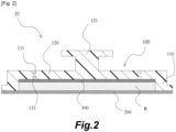
- Fig. 2 is a schematic sectional view of the container according to the first embodiment of the present invention, and a sectional view taken along a plane indicated by AA in Fig. 1A .
- Figs. 3A and 3B are schematic views showing the container in use according to the first embodiment of the present invention. Note that Fig.
- FIG. 3A is a plan view showing a state in which a lid of the container according to this embodiment has been removed
- Fig. 3B is a sectional view taken along a plane indicated by BB in Fig. 3A
- Figs. 4A and 4B are schematic views of a microfluidic chip to which the container according to the first embodiment of the present invention can be applied.
- Fig. 4A is a plan view of the microfluidic chip to which the container according to this embodiment can be applied
- Fig. 4B is a sectional view taken along a plane indicated by CC in Fig. 4A .
- FIG. 5A and 5B are schematic views of a microfluidic device and a diaphragm pump (application example 1) to which the container according to the first embodiment of the present invention can be applied.
- Fig. 5A is a schematic sectional view of the microfluidic device to which the container according to this embodiment can be applied, and the container in this figure is that is shown in Fig. 2 and the microfluidic chip in this figure is that is shown in Fig. 4B .
- Fig. 5B is a schematic view of the pump to which the container according to this embodiment can be applied, and the container in this figure is that is shown in Fig. 3B and the microfluidic chip in this figure is that is shown in Fig. 4B .
- Figs. 6A and 6B are schematic views of a microfluidic device and a diaphragm pump (application example 2) to which the container according to the first embodiment of the present invention can be applied.
- Fig. 6A is a schematic sectional view of the microfluidic device to which the container according to this embodiment can be applied, and the container in this figure is that is shown in Fig. 2 .
- Fig. 6B is a schematic view of the pump to which the container according to this embodiment can be applied, and the container in this figure is that is shown in Fig. 3B .
- the container 10 includes a case 100.
- the material of the case 100 may be selected in accordance with a fluid R to be sealed in the case 100.
- the material used for the case 100 may be a resin material having a superior gas barrier property. More specifically, polyvinylidene chloride, ethylene vinyl alcohol copolymer resin, and so on can be used as appropriate. Alternatively, a multilayer structure may be used which includes layers of these resin materials having the superior gas barrier properties.
- the case 100 includes a case body 110 including a tubular portion, a lid 120, and a handle 121, these components being formed integrally.
- the tubular portion of the case body 110 is constituted by a cylindrical part.
- the container 10 includes a thin film 200 that closes an opening on one end side of the tubular portion of the case body 110.
- the material of the thin film 200 may be selected in accordance with the fluid R sealed in the case 100.
- the material used for the thin film 200 may be a material having a superior gas barrier property.
- the thin film 200 may be formed from a single-layer film constituted by an aluminum film, a plastic film, or the like, or a multilayer film formed from these materials.
- the container 10 includes a diaphragm 300 that closes an opening on the other end side of the tubular portion of the case body 110.
- the diaphragm 300 may be formed from an elastomer material, and more specifically, silicone rubber, which exhibits superior chemical stability and biocompatibility, may be used. By using silicone rubber, target cells can be protected.
- an enclosed space is formed by the tubular portion of the case body 110, the thin film 200, and the diaphragm 300.
- the fluid R such as a sample or a reagent, is sealed in the interior of the enclosed space. Note that the fluid R can be sealed in the interior of the enclosed space by pouring the fluid R into the case body 110 in a state where the diaphragm 300 is provided therein, and then attaching the thin film 200.
- the lid 120 is provided on the other end side of the case body 110 on a side opposite to the thin film 200 with respect to the diaphragm 300 in order to close off the diaphragm 300 from the outside space.
- the lid 120 is provided integrally with the case body 110.
- a boundary between the lid 120 and the case body 110 is constituted by a thin part. More specifically, the thin part is formed by providing grooves 131 and 132 having circular shapes in plan view in front and rear surfaces, respectively.
- the handle 121 to be pulled in order to tear the thin part is provided on the lid 120, and by pulling the handle 121, a user can tear the thin part and thus remove the lid 120 from the case body 110.
- the diaphragm 300 can be exposed at the time of use.
- Figs. 3A and 3B show a state in which the lid 120 has been removed from the case body 110.
- FIG. 4A a microfluidic chip 400 to which the container 10 according to this embodiment can be applied will be described. Note that in Fig. 4A , parts visible in transparent view are indicated by dotted lines.
- the microfluidic chip 400 is a thin plate-shaped member formed from acrylic, glass, a resin material, or the like.
- the microfluidic chip 400 is provided with a recessed portion 410 serving as an attachment portion to which the case body 110 of the container 10 can be attached.
- An inner wall surface of the recessed portion 410 is constituted by a columnar surface and is configured such that the outer peripheral surface of the tubular portion of the case body 110 can be fitted thereto.
- a projecting portion 420 for puncturing the thin film 200 of the container 10 is provided on the microfluidic chip 400 in the center of the bottom surface of the recessed portion 410. Further, a flow passage 430 for the fluid R is provided in the microfluidic chip 400 so as to connect to the recessed portion 410. Furthermore, the microfluidic chip 400 is provided with a storage tank 440 connected to the flow passage 430, and an extraction port 450 through which the fluid R is extracted.
- FIGs. 5A and 5B an example application (application example 1) of a microfluidic device and a diaphragm pump to which the container 10 according to this embodiment can be applied will be described.
- Fig. 5A shows a microfluidic device 10S according to application example 1.
- the microfluidic device 10S is constituted by the microfluidic chip 400 and the container 10. Note that in this application example, the microfluidic chip 400 shown in Figs. 4A and 4B and described above is used.
- the microfluidic device 10S can be obtained by fitting the case body 110 into the recessed portion 410 of the microfluidic chip 400 so as to attach the container 10 to the microfluidic chip 400.
- the projecting portion 420 punctures the thin film 200 of the container 10, thereby forming an outflow port for the fluid R.
- Fig. 5B shows a diaphragm pump 10T according to application example 1.
- the diaphragm pump 10T includes the microfluidic device 10S and a pressing mechanism 500.
- the pressing mechanism 500 includes a pressing member 510 for pressing the diaphragm 300 of the container 10, and an actuator 520 for causing the pressing member 510 to perform a reciprocating motion.
- any of various known techniques such as a ball screw mechanism, a rack and pinion mechanism, a hydraulic mechanism, or a pneumatic mechanism, may be employed as the actuator 520.
- the solid lines indicate a state in which the pressing member 510 is separated from the diaphragm 300
- the dotted lines indicate a state in which the pressing member 510 is pressed against the diaphragm 300.
- FIGs. 6A and 6B an example application (application example 2) of a microfluidic device and a diaphragm pump to which the container 10 according to this embodiment can be applied will be described.
- Fig. 6A shows a microfluidic device 10SA according to application example 2.
- the microfluidic device 10SA is constituted by a microfluidic chip 400A and the container 10.
- the microfluidic chip 400A according to this application example employs a different configuration from the microfluidic chip 400 shown in Figs. 4A and 4B and described above.
- the microfluidic chip 400A similarly to the microfluidic chip 400 described above, includes the recessed portion 410 serving as the attachment portion, the projecting portion 420, and the flow passage 430.
- the recessed portion 410 and the projecting portion 420 are provided on both sides of the flow passage 430, while the storage tank 440 and the extraction port 450 are not provided.
- a ventilation port not shown in the figures, that is used to allow air and the like to escape from the flow passage 430 and so on is provided in the microfluidic chip 400A.
- the microfluidic device 10SA can be obtained by fitting the case body 110 into each of the recessed portions 410 provided in two locations of the microfluidic chip 400A such that two containers 10 are attached.
- the projecting portions 420 puncture the thin films 200 of the respective containers 10, thereby respectively forming outflow ports for fluids R1 and R2.
- Fig. 6B shows a diaphragm pump 10TA according to application example 2.
- the diaphragm pump 10TA includes the microfluidic device 10SA and a pair of pressing mechanisms 500.
- the lid 120 is removed from the case body 110.
- the pressing mechanism 500 is configured as described in the application example 1.
- the fluids R1 and R2 can be caused to move through the flow passage 430 in a reciprocating manner.
- the fluids can be mixed.
- the container 10 by pressing the diaphragm 300 in a state where the outflow port has been formed in the thin film 200, the fluid sealed inside the case body 110 can be caused to flow out. Further, since the fluid is caused to flow out by pressing the diaphragm 300, the outflow rate of the fluid can be controlled more easily than a configuration in which a container that undergoes plastic deformation is used. Furthermore, the container 10 can also be caused to function as part of the diaphragm pump 10T, 10TA.
- the lid 120 is provided on the case 100 of the container 10, and therefore the diaphragm 300 is not exposed to the outside during storage or transportation of the container 10. This can prevent leakage of the fluid due to damage to the diaphragm 300 or the diaphragm 300 being pressed.
- the lid 120 is removable from the case body 110, and when the container 10 is used as the diaphragm pump 10T, 10TA, the lid 120 need simply be removed from the case body 110.
- the lid 120 can easily be removed from the case body 110 by pulling the handle 121.
- the diaphragm 300 is gas-permeable, by forming the case 100 and the thin film 200 from materials having a gas barrier property, volatilization of the fluid R in the enclosed space can be suppressed prior to use.
- the fluid sealed inside the container 10 can be supplied to the flow passage 430 of the microfluidic chip 400, 400A simply by attaching the container 10 to the microfluidic chip 400, 400A. This saves space and reduces the number of components.
- the microfluidic device 10S, 10SA according to this embodiment can be obtained by attaching the container 10 to the microfluidic chip 400, 400A.
- the fluid R sealed inside the container 10 can be supplied to the flow passage 430 provided in the microfluidic chip 400, 400A immediately after attaching the container 10, and this can prevent foreign matter from entering the fluid R.
- FIG. 7 is a schematic sectional view of the container according to the second embodiment of the present invention, which is obtained by cutting the container in the same location as the sectional view shown in Fig. 2 in the first embodiment.
- a container 10A according to this embodiment includes the case 100, a thin film 200A, and the diaphragm 300.
- the case 100 and the diaphragm 300 are as described in the first embodiment.
- the configuration of the thin film 200A itself is as described in the first embodiment, but the structure for attaching the thin film 200A to the case body 110 differs from the first embodiment.
- the thin film 200A is sandwiched between a first guide member 600 and a second guide member 700 respectively having through holes 610 and 710 through which the projecting portion 420 of the microfluidic chip 400 or 400A can be inserted.
- the first guide member 600 is provided on the diaphragm 300 side, and the second guide member 700 is provided on a side opposite to the first guide member 600 with respect to the thin film 200A.
- the first guide member 600 is fixed to the case body 110.
- first guide member 600 is formed from a hard material (a hard resin material or the like), while the second guide member 700 is formed from an elastomer material such as rubber.
- container 10A according to this embodiment can be used in place of the container 10 in the microfluidic device and diaphragm pump described in the first embodiment.
- Similar effects to the first embodiment can be obtained with the container 10A configured as described above. Moreover, with the container 10A according to this embodiment, when the container 10A is attached to the microfluidic chip, positional deviation of the projecting portion 420 is suppressed by the through holes 610 and 710, and therefore the operation for puncturing the thin film 200A with the projecting portion 420 is performed smoothly. Furthermore, since the first guide member 600 is formed from a hard material, sufficient force can be applied when the container 10A is attached to the microfluidic chip. This prevents the container 10A from being insufficiently attached.
- the second guide member 700 can be brought into close contact with the bottom surface of the recessed portion 410 of the microfluidic chip 400 or 400A. This prevents leakage of the fluid to the outside.
- FIG. 8 is a schematic sectional view of the container according to the third embodiment of the present invention, which is obtained by cutting the container in the same location as the sectional view shown in Fig. 2 in the first embodiment.
- a container 10B according to this embodiment includes the case 100, the thin film 200A, and the diaphragm 300.
- the case 100 and the diaphragm 300 are as described in the first embodiment.
- the configuration of the thin film 200A itself is as described in the first embodiment, but the structure for attaching the thin film 200A to the case body 110 differs from the first embodiment.
- the thin film 200A is sandwiched between a first guide member 600B and the second guide member 700 respectively having the through holes 610 and 710 through which the projecting portion 420 of the microfluidic chip 400 or 400A can be inserted.
- the first guide member 600B is provided on the diaphragm 300 side, and the second guide member 700 is provided on a side opposite to the first guide member 600 with respect to the thin film 200A.
- the first guide member 600B is fixed to the case body 110.
- first guide member 600B is formed from a hard material (a hard resin material or the like), while the second guide member 700 is formed from an elastomer material such as rubber.
- the container 10B according to this embodiment can be used in place of the container 10 in the microfluidic device and diaphragm pump described in the first embodiment.
- a surface 620 thereof on the diaphragm 300 side is formed from an inclined surface that decreases in diameter toward the through hole 610.
- the inclined surface is constituted by a tapered surface, but a configuration other than a tapered surface (for example, an inclined surface that is curved rather than linear in a sectional view) may be employed as the inclined surface.
- the surface 620 on the diaphragm 300 side is formed from an inclined surface, and therefore, when the diaphragm 300 is pressed such that the fluid R flows out, fluid can be prevented from remaining inside the container.
- the case 100 includes the lid 120
- the lid 120 may be omitted.
- the lid 120 of the case 100 may not be included, and a configuration not including the lid 120 may be employed in the case 100.
Landscapes
- Chemical & Material Sciences (AREA)
- Health & Medical Sciences (AREA)
- Chemical Kinetics & Catalysis (AREA)
- Clinical Laboratory Science (AREA)
- Engineering & Computer Science (AREA)
- General Engineering & Computer Science (AREA)
- Medicinal Chemistry (AREA)
- Mechanical Engineering (AREA)
- Dispersion Chemistry (AREA)
- Analytical Chemistry (AREA)
- General Health & Medical Sciences (AREA)
- Hematology (AREA)
- Reciprocating Pumps (AREA)
Abstract
Description
- The present invention relates to a container, a microfluidic device, and a diaphragm pump.
- In a known conventional technique relating to a microfluidic device that uses a microfluidic chip, a small flow passage and a reaction vessel are provided in a small chip, and a reaction process and so on are implemented using a small amount of reagent. According to this technique, a test that uses an expensive reagent can be performed using a small amount of the reagent. Another known technique relates to a container in which a fluid such as a reagent that is supplied to a microfluidic chip is sealed.
- With a container having a conventional structure, however, it is difficult to control the flow rate of the fluid, such as the reagent supplied to the microfluidic chip. Moreover, the only function of a container having a conventional structure is as a container for housing a fluid.
-
- [PTL 1]
Japanese Patent Application Publication No. H9-175538 - [PTL 2]
Japanese Patent Application Publication No. 2017-121970 - The present invention provides a container with which the outflow rate of a fluid can easily be controlled, and which can be caused to function as part of a configuration of a diaphragm pump, as well as a microfluidic device and a diaphragm pump.
- To solve the problems described above, the present invention employs the following means.
- A container of the present invention includes:
- a case body that includes a tubular portion in which a fluid is to be sealed;
- a thin film that closes an opening on one end side of the tubular portion, and that is to be punctured so as to form an outflow port for the fluid therein; and
- a diaphragm that closes an opening on the other end side of the tubular portion.
- According to the present invention, by pressing the diaphragm in a state where the outflow port has been formed in the thin film, the fluid sealed inside the case body can be caused to flow out. Further, since the fluid is caused to flow out by pressing the diaphragm, the outflow rate of the fluid can easily be controlled. Furthermore, the container can also be caused to function as part of a diaphragm pump.
- On the other end side of the case body, a lid that closes off the diaphragm from an outside space may be provided on a side opposite to the thin film with respect to the diaphragm.
- This prevents the diaphragm from being exposed to the outside during storage or transportation of the container.
- The lid may be provided integrally with the case body, a boundary between the lid and the case body may be constituted by a thin part, and the lid may be removable from the case body by tearing the thin part.
- Thus, by removing the lid from the case body, the fluid can be supplied to a microfluidic chip or the like, and the container can be used as a diaphragm pump.
- A handle to be pulled to tear the thin part may be provided on the lid.
- This allows the lid to be easily removed from the case body.
- Further, the case body may be formed from a material having a gas barrier property.
- Furthermore, the thin film may be formed from a material having a gas barrier property.
- Moreover, the diaphragm may be formed from an elastomer material.
- The container can be attached to a microfluidic chip that includes an attachment portion to which the case body is attached, a projecting portion for puncturing the thin film, and a flow passage for the fluid.
- The thin film may be sandwiched between a first guide member and a second guide member, each of which has a through hole through which the projecting portion is inserted, the first guide member being provided on the diaphragm side and the second guide member being provided on a side opposite to the first guide member with respect to the thin film.
- Thus, when the container is attached to the microfluidic chip, positional deviation of the projecting portion can be suppressed by the through holes, and as a result, the operation for puncturing the thin film with the projecting portion can be performed smoothly.
- The fluid may be sealed in a space between the diaphragm and the first guide member, and a surface of the first guide member on the diaphragm side may be constituted by an inclined surface that decreases in diameter toward the through hole.
- This prevents the fluid from remaining inside the container when the diaphragm is pressed such that the fluid flows out.
- The first guide member may be formed from a hard material and the second guide member may be formed from an elastomer material.
- This enhances a function of the first guide member as a guide for suppressing positional deviation of the projecting portion, and a function of the second guide member for suppressing leakage of the fluid to the outside.
- Furthermore, a guide member having a through hole through which the projecting portion is inserted may be provided between the case body and the thin film, the fluid may be sealed in a space between the diaphragm and the guide member, and a surface of the guide member on the diaphragm side may be constituted by an inclined surface that decreases in diameter toward the through hole.
- Further, a microfluidic device according to the present invention may include:
- a microfluidic chip including an attachment portion to which the case body is attached, a projecting portion for puncturing the thin film, and a flow passage for the fluid; and
- the container described above, which is attached to the microfluidic chip by attaching the case body to the attachment portion.
- Furthermore, a diaphragm pump according to the present invention may include:
- the microfluidic device described above;
- a pressing member configured to press the diaphragm; and
- an actuator configured to cause the pressing member to perform a reciprocating motion.
- Note that the configurations described above may be employed in any possible combinations.
- According to the present invention, as described above, it is possible to provide a container with which the outflow rate of a fluid can easily be controlled, and which can be caused to function as part of the configuration of a diaphragm pump, as well as a microfluidic device and a diaphragm pump.
-
- [
Fig. 1 ]
Figs. 1A and 1B are schematic views of a container according to a first embodiment of the present invention. - [
Fig. 2 ]
Fig. 2 is a schematic sectional view of the container according to the first embodiment of the present invention. - [
Fig. 3 ]
Figs. 3A and 3B are schematic views showing the container in use according to the first embodiment of the present invention. - [
Fig. 4 ]
Figs. 4A and 4B are schematic views of a microfluidic chip to which the container according to the first embodiment of the present invention can be applied. - [
Fig. 5 ]
Figs. 5A and 5B are schematic views of a microfluidic device and a diaphragm pump to which the container according to the first embodiment of the present invention can be applied. - [
Fig. 6 ]
Figs. 6A and 6B are schematic views of a microfluidic device and a diaphragm pump to which the container according to the first embodiment of the present invention can be applied. - [
Fig. 7 ]
Fig. 7 is a schematic sectional view of a container according to a second embodiment of the present invention. - [
Fig. 8 ]
Fig. 8 is a schematic sectional view of a container according to a third embodiment of the present invention. - Exemplary forms to implement the invention will be described in detail below with reference to the figures on the basis of embodiments. Note, however, that unless specifically indicated otherwise, the scope of the invention is not limited only to the dimensions, materials, shapes, relative arrangements, and so on of the constituent components described in the embodiments.
- A container, a microfluidic device, and a diaphragm pump according to a first embodiment of the present invention will be described with reference to
Figs. 1 to 6 .Figs. 1A and 1B are schematic views of a container according to the first embodiment of the present invention. Note thatFig. 1A is a plan view of the container according to this embodiment, andFig. 1B is a back surface view thereof.Fig. 2 is a schematic sectional view of the container according to the first embodiment of the present invention, and a sectional view taken along a plane indicated by AA inFig. 1A .Figs. 3A and 3B are schematic views showing the container in use according to the first embodiment of the present invention. Note thatFig. 3A is a plan view showing a state in which a lid of the container according to this embodiment has been removed, andFig. 3B is a sectional view taken along a plane indicated by BB inFig. 3A .Figs. 4A and 4B are schematic views of a microfluidic chip to which the container according to the first embodiment of the present invention can be applied. Note thatFig. 4A is a plan view of the microfluidic chip to which the container according to this embodiment can be applied, andFig. 4B is a sectional view taken along a plane indicated by CC inFig. 4A .Figs. 5A and 5B are schematic views of a microfluidic device and a diaphragm pump (application example 1) to which the container according to the first embodiment of the present invention can be applied. Note thatFig. 5A is a schematic sectional view of the microfluidic device to which the container according to this embodiment can be applied, and the container in this figure is that is shown inFig. 2 and the microfluidic chip in this figure is that is shown inFig. 4B . - Further,
Fig. 5B is a schematic view of the pump to which the container according to this embodiment can be applied, and the container in this figure is that is shown inFig. 3B and the microfluidic chip in this figure is that is shown inFig. 4B .Figs. 6A and 6B are schematic views of a microfluidic device and a diaphragm pump (application example 2) to which the container according to the first embodiment of the present invention can be applied. Note thatFig. 6A is a schematic sectional view of the microfluidic device to which the container according to this embodiment can be applied, and the container in this figure is that is shown inFig. 2 . Further,Fig. 6B is a schematic view of the pump to which the container according to this embodiment can be applied, and the container in this figure is that is shown inFig. 3B . - Referring specifically to
Figs. 1 to 3 , acontainer 10 according to this embodiment will be described. Thecontainer 10 includes acase 100. The material of thecase 100 may be selected in accordance with a fluid R to be sealed in thecase 100. For example, when the fluid R is volatile, the material used for thecase 100 may be a resin material having a superior gas barrier property. More specifically, polyvinylidene chloride, ethylene vinyl alcohol copolymer resin, and so on can be used as appropriate. Alternatively, a multilayer structure may be used which includes layers of these resin materials having the superior gas barrier properties. Thecase 100 includes acase body 110 including a tubular portion, alid 120, and ahandle 121, these components being formed integrally. In this embodiment, the tubular portion of thecase body 110 is constituted by a cylindrical part. - Further, the
container 10 includes athin film 200 that closes an opening on one end side of the tubular portion of thecase body 110. The material of thethin film 200 may be selected in accordance with the fluid R sealed in thecase 100. For example, when the fluid R is volatile, the material used for thethin film 200 may be a material having a superior gas barrier property. For example, thethin film 200 may be formed from a single-layer film constituted by an aluminum film, a plastic film, or the like, or a multilayer film formed from these materials. - Furthermore, the
container 10 includes adiaphragm 300 that closes an opening on the other end side of the tubular portion of thecase body 110. Thediaphragm 300 may be formed from an elastomer material, and more specifically, silicone rubber, which exhibits superior chemical stability and biocompatibility, may be used. By using silicone rubber, target cells can be protected. - In the
container 10 configured as described above, an enclosed space is formed by the tubular portion of thecase body 110, thethin film 200, and thediaphragm 300. The fluid R, such as a sample or a reagent, is sealed in the interior of the enclosed space. Note that the fluid R can be sealed in the interior of the enclosed space by pouring the fluid R into thecase body 110 in a state where thediaphragm 300 is provided therein, and then attaching thethin film 200. - The
lid 120 is provided on the other end side of thecase body 110 on a side opposite to thethin film 200 with respect to thediaphragm 300 in order to close off thediaphragm 300 from the outside space. Thus, even if thediaphragm 300 is gas-permeable, volatilization of the fluid R in the enclosed space can be suppressed. - Furthermore, as described above, the
lid 120 is provided integrally with thecase body 110. A boundary between thelid 120 and thecase body 110 is constituted by a thin part. More specifically, the thin part is formed by providinggrooves
respectively. Thus, when the thin part is torn, thelid 120 is removed from thecase body 110. Hence, thelid 120 is removable from thecase body 110. In this embodiment, thehandle 121 to be pulled in order to tear the thin part is provided on thelid 120, and by pulling thehandle 121, a user can tear the thin part and thus remove thelid 120 from thecase body 110. As a result, thediaphragm 300 can be exposed at the time of use. Note thatFigs. 3A and 3B show a state in which thelid 120 has been removed from thecase body 110. - Referring to
Figs. 4A and 4B in particular, amicrofluidic chip 400 to which thecontainer 10 according to this embodiment can be applied will be described. Note that inFig. 4A , parts visible in transparent view are indicated by dotted lines. - The
microfluidic chip 400 is a thin plate-shaped member formed from acrylic, glass, a resin material, or the like. Themicrofluidic chip 400 is provided with a recessedportion 410 serving as an attachment portion to which thecase body 110 of thecontainer 10 can be attached. An inner wall surface of the recessedportion 410 is constituted by a columnar surface and is configured such that the outer peripheral surface of the tubular portion of thecase body 110 can be fitted thereto. - A projecting
portion 420 for puncturing thethin film 200 of thecontainer 10 is provided on themicrofluidic chip 400 in the center of the bottom surface of the recessedportion 410. Further, aflow passage 430 for the fluid R is provided in themicrofluidic chip 400 so as to connect to the recessedportion 410. Furthermore, themicrofluidic chip 400 is provided with astorage tank 440 connected to theflow passage 430, and anextraction port 450 through which the fluid R is extracted. - Referring to
Figs. 5A and 5B , an example application (application example 1) of a microfluidic device and a diaphragm pump to which thecontainer 10 according to this embodiment can be applied will be described. -
Fig. 5A shows amicrofluidic device 10S according to application example 1. Themicrofluidic device 10S is constituted by themicrofluidic chip 400 and thecontainer 10. Note that in this application example, themicrofluidic chip 400 shown inFigs. 4A and 4B and described above is used. Themicrofluidic device 10S can be obtained by fitting thecase body 110 into the recessedportion 410 of themicrofluidic chip 400 so as to attach thecontainer 10 to themicrofluidic chip 400. When thecontainer 10 is attached to themicrofluidic chip 400, the projectingportion 420 punctures thethin film 200 of thecontainer 10, thereby forming an outflow port for the fluid R. -
Fig. 5B shows adiaphragm pump 10T according to application example 1. Thediaphragm pump 10T includes themicrofluidic device 10S and apressing mechanism 500. When themicrofluidic device 10S is to be used as thediaphragm pump 10T, thelid 120 is removed from thecase body 110. Thepressing mechanism 500 includes apressing member 510 for pressing thediaphragm 300 of thecontainer 10, and anactuator 520 for causing thepressing member 510 to perform a reciprocating motion. Note that any of various known techniques, such as a ball screw mechanism, a rack and pinion mechanism, a hydraulic mechanism, or a pneumatic mechanism, may be employed as theactuator 520. As to thepressing member 510 inFig. 5B , the solid lines indicate a state in which thepressing member 510 is separated from thediaphragm 300, while the dotted lines indicate a state in which thepressing member 510 is pressed against thediaphragm 300. When thediaphragm 300 is pressed by the pressingmember 510, the fluid R sealed inside thecontainer 10 is supplied to theflow passage 430 of themicrofluidic chip 400 through the outflow port formed in thethin film 200 as indicated by the dotted arrow. Note that when thepressing member 510 is separated from thediaphragm 300, thediaphragm 300 returns to its original state. Thus, an operation for causing the fluid R to flow back can also be performed. - Referring to
Figs. 6A and 6B , an example application (application example 2) of a microfluidic device and a diaphragm pump to which thecontainer 10 according to this embodiment can be applied will be described. -
Fig. 6A shows a microfluidic device 10SA according to application example 2. The microfluidic device 10SA is constituted by amicrofluidic chip 400A and thecontainer 10. Themicrofluidic chip 400A according to this application example employs a different configuration from themicrofluidic chip 400 shown inFigs. 4A and 4B and described above. Themicrofluidic chip 400A, similarly to themicrofluidic chip 400 described above, includes the recessedportion 410 serving as the attachment portion, the projectingportion 420, and theflow passage 430. In contrast to themicrofluidic chip 400 described above, in themicrofluidic chip 400A according to application example 2, the recessedportion 410 and the projectingportion 420 are provided on both sides of theflow passage 430, while thestorage tank 440 and theextraction port 450 are not provided. Note, however, that a ventilation port, not shown in the figures, that is used to allow air and the like to escape from theflow passage 430 and so on is provided in themicrofluidic chip 400A. - In this application example, the microfluidic device 10SA can be obtained by fitting the
case body 110 into each of the recessedportions 410 provided in two locations of themicrofluidic chip 400A such that twocontainers 10 are attached. When the twocontainers 10 are attached to themicrofluidic chip 400A, the projectingportions 420 puncture thethin films 200 of therespective containers 10, thereby respectively forming outflow ports for fluids R1 and R2. -
Fig. 6B shows a diaphragm pump 10TA according to application example 2. The diaphragm pump 10TA includes the microfluidic device 10SA and a pair of pressingmechanisms 500. When the microfluidic device 10SA is used as the diaphragm pump 10TA, thelid 120 is removed from thecase body 110. Thepressing mechanism 500 is configured as described in the application example 1. In this application example, by pressing thediaphragms 300 of the twocontainers 10 alternately using the twopressing mechanisms 500, for example, the fluids R1 and R2 can be caused to move through theflow passage 430 in a reciprocating manner. When different samples or reagents are used as the fluid R1 and the fluid R2, the fluids can be mixed. - With the
container 10 according to this embodiment, by pressing thediaphragm 300 in a state where the outflow port has been formed in thethin film 200, the fluid sealed inside thecase body 110 can be caused to flow out. Further, since the fluid is caused to flow out by pressing thediaphragm 300, the outflow rate of the fluid can be controlled more easily than a configuration in which a container that undergoes plastic deformation is used. Furthermore, thecontainer 10 can also be caused to function as part of thediaphragm pump 10T, 10TA. - In a state prior to use, the
lid 120 is provided on thecase 100 of thecontainer 10, and therefore thediaphragm 300 is not exposed to the outside during storage or transportation of thecontainer 10. This can prevent leakage of the fluid due to damage to thediaphragm 300 or thediaphragm 300 being pressed. Moreover, thelid 120 is removable from thecase body 110, and when thecontainer 10 is used as thediaphragm pump 10T, 10TA, thelid 120 need simply be removed from thecase body 110. Furthermore, in this embodiment, thelid 120 can easily be removed from thecase body 110 by pulling thehandle 121. Moreover, even when thediaphragm 300 is gas-permeable, by forming thecase 100 and thethin film 200 from materials having a gas barrier property, volatilization of the fluid R in the enclosed space can be suppressed prior to use. - Further, the fluid sealed inside the
container 10 can be supplied to theflow passage 430 of themicrofluidic chip container 10 to themicrofluidic chip - Furthermore, the
microfluidic device 10S, 10SA according to this embodiment can be obtained by attaching thecontainer 10 to themicrofluidic chip container 10 can be supplied to theflow passage 430 provided in themicrofluidic chip container 10, and this can prevent foreign matter from entering the fluid R. - Referring to
Fig. 7 , a container according to a second embodiment of the present invention will be described. The configuration of the container of this embodiment partially differs from that of the first embodiment. The basic configuration and operations are identical to the first embodiment, and therefore identical constituent parts have been allocated identical reference numerals and description thereof has been omitted where appropriate.Fig. 7 is a schematic sectional view of the container according to the second embodiment of the present invention, which is obtained by cutting the container in the same location as the sectional view shown inFig. 2 in the first embodiment. - A container 10A according to this embodiment includes the
case 100, athin film 200A, and thediaphragm 300. Thecase 100 and thediaphragm 300 are as described in the first embodiment. - In this embodiment, the configuration of the
thin film 200A itself is as described in the first embodiment, but the structure for attaching thethin film 200A to thecase body 110 differs from the first embodiment. In this embodiment, thethin film 200A is sandwiched between afirst guide member 600 and asecond guide member 700 respectively having throughholes portion 420 of themicrofluidic chip first guide member 600 is provided on thediaphragm 300 side, and thesecond guide member 700 is provided on a side opposite to thefirst guide member 600 with respect to thethin film 200A. Thefirst guide member 600 is fixed to thecase body 110. Further, thefirst guide member 600 is formed from a hard material (a hard resin material or the like), while thesecond guide member 700 is formed from an elastomer material such as rubber. Note that the container 10A according to this embodiment can be used in place of thecontainer 10 in the microfluidic device and diaphragm pump described in the first embodiment. - Similar effects to the first embodiment can be obtained with the container 10A configured as described above. Moreover, with the container 10A according to this embodiment, when the container 10A is attached to the microfluidic chip, positional deviation of the projecting
portion 420 is suppressed by the throughholes thin film 200A with the projectingportion 420 is performed smoothly. Furthermore, since thefirst guide member 600 is formed from a hard material, sufficient force can be applied when the container 10A is attached to the microfluidic chip. This prevents the container 10A from being insufficiently attached. Moreover, by forming thesecond guide member 700 from an elastomer material such as rubber, thesecond guide member 700 can be brought into close contact with the bottom surface of the recessedportion 410 of themicrofluidic chip - Referring to
Fig. 8 , a container according to a third embodiment of the present invention will be described. The shape of the first guide member of this embodiment differs from that of the second embodiment. The basic configuration and operations are identical to the second embodiment, and therefore identical constituent parts have been allocated identical reference numerals and description thereof has been omitted where appropriate.Fig. 8 is a schematic sectional view of the container according to the third embodiment of the present invention, which is obtained by cutting the container in the same location as the sectional view shown inFig. 2 in the first embodiment. - A
container 10B according to this embodiment includes thecase 100, thethin film 200A, and thediaphragm 300. Thecase 100 and thediaphragm 300 are as described in the first embodiment. - In this embodiment, the configuration of the
thin film 200A itself is as described in the first embodiment, but the structure for attaching thethin film 200A to thecase body 110 differs from the first embodiment. In this embodiment, thethin film 200A is sandwiched between afirst guide member 600B and thesecond guide member 700 respectively having the throughholes portion 420 of themicrofluidic chip first guide member 600B is provided on thediaphragm 300 side, and thesecond guide member 700 is provided on a side opposite to thefirst guide member 600 with respect to thethin film 200A. Thefirst guide member 600B is fixed to thecase body 110. Further, thefirst guide member 600B is formed from a hard material (a hard resin material or the like), while thesecond guide member 700 is formed from an elastomer material such as rubber. Note that thecontainer 10B according to this embodiment can be used in place of thecontainer 10 in the microfluidic device and diaphragm pump described in the first embodiment. - In the
first guide member 600B according to this embodiment, asurface 620 thereof on thediaphragm 300 side is formed from an inclined surface that decreases in diameter toward the throughhole 610. Note that in this embodiment, the inclined surface is constituted by a tapered surface, but a configuration other than a tapered surface (for example, an inclined surface that is curved rather than linear in a sectional view) may be employed as the inclined surface. - Similar effects to the first and second embodiments can be obtained with the
container 10B configured as described above. Moreover, in this embodiment, thesurface 620 on thediaphragm 300 side is formed from an inclined surface, and therefore, when thediaphragm 300 is pressed such that the fluid R flows out, fluid can be prevented from remaining inside the container. - Furthermore, it was found through verification that, depending on the use conditions, no problems occurred in terms of quality in the
container 10B according to this embodiment even if thesecond guide member 700 was omitted. Accordingly, a container configured not to include thesecond guide member 700 among the components of thecontainer 10B can also be employed. - Configurations in which the
case 100 includes thelid 120 were illustrated in the embodiments described above. However, depending on the type of the sealed fluid R, the material of thediaphragm 300, and the storage and transportation conditions, thelid 120 may be omitted. Hence, depending on various conditions, thelid 120 of thecase 100 may not be included, and a configuration not including thelid 120 may be employed in thecase 100. -
- 10, 10A, 10B Container
- 10S, 10SA Microfluidic device
- 10T, 10TA Diaphragm pump
- 100 Case
- 110 Case body
- 120 Lid
- 121 Handle
- 131, 132 Groove
- 200, 200A Thin film
- 300 Diaphragm
- 400, 400A Microfluidic chip
- 410 Recessed portion
- 420 Projecting portion
- 430 Flow passage
- 440 Storage tank
- 450 Extraction port
- 500 Pressing mechanism
- 510 Pressing member
- 520 Actuator
- 610, 710 Through hole
- R, R1, R2 Fluid
Claims (14)
- A container comprising:a case body that includes a tubular portion in which a fluid is to be sealed;a thin film that closes an opening on one end side of the tubular portion, and that is to be punctured so as to form an outflow port for the fluid therein; anda diaphragm that closes an opening on the other end side of the tubular portion.
- The container according to claim 1, wherein, on the other end side of the case body, a lid that closes off the diaphragm from an outside space is provided on a side opposite to the thin film with respect to the diaphragm.
- The container according to claim 2, wherein the lid is provided integrally with the case body, a boundary between the lid and the case body is constituted by a thin part, and the lid is removable from the case body by tearing the thin part.
- The container according to claim 3, wherein a handle to be pulled to tear the thin part is provided on the lid.
- The container according to any one of claims 1 to 4, wherein the case body is formed from a material having a gas barrier property.
- The container according to any one of claims 1 to 5, wherein the thin film is formed from a material having a gas barrier property.
- The container according to any one of claims 1 to 6, wherein the diaphragm is formed from an elastomer material.
- The container according to any one of claims 1 to 7, wherein the container is attached to a microfluidic chip comprising an attachment portion to which the case body is attached, a projecting portion for puncturing the thin film, and a flow passage for the fluid.
- The container according to claim 8, wherein the thin film is sandwiched between a first guide member and a second guide member, each of which has a through hole through which the projecting portion is inserted, the first guide member being provided on the diaphragm side and the second guide member being provided on a side opposite to the first guide member with respect to the thin film.
- The container according to claim 9, wherein the fluid is sealed in a space between the diaphragm and the first guide member, and a surface of the first guide member on the diaphragm side is constituted by an inclined surface that decreases in diameter toward the through hole.
- The container according to claim 9 or 10, wherein the first guide member is formed from a hard material and the second guide member is formed from an elastomer material.
- The container according to claim 8, whereina guide member having a through hole through which the projecting portion is inserted is provided between the case body and the thin film,the fluid is sealed in a space between the diaphragm and the guide member, anda surface of the guide member on the diaphragm side is constituted by an inclined surface that decreases in diameter toward the through hole.
- A microfluidic device comprising:a microfluidic chip including an attachment portion to which a case body is attached, a projecting portion for puncturing the thin film, and a flow passage for the fluid; andthe container according to any one of claims 1 to 12, which is attached to the microfluidic chip by attaching the case body to the attachment portion.
- A diaphragm pump comprising:the microfluidic device according to claim 13;a pressing member configured to press the diaphragm; andan actuator configured to cause the pressing member to perform a reciprocating motion.
Applications Claiming Priority (2)
| Application Number | Priority Date | Filing Date | Title |
|---|---|---|---|
| JP2022002153 | 2022-01-11 | ||
| PCT/JP2022/045153 WO2023135991A1 (en) | 2022-01-11 | 2022-12-07 | Container, microfluidic device, and diaphragm pump |
Publications (2)
| Publication Number | Publication Date |
|---|---|
| EP4464894A1 true EP4464894A1 (en) | 2024-11-20 |
| EP4464894A4 EP4464894A4 (en) | 2025-07-30 |
Family
ID=87278806
Family Applications (1)
| Application Number | Title | Priority Date | Filing Date |
|---|---|---|---|
| EP22920511.7A Pending EP4464894A4 (en) | 2022-01-11 | 2022-12-07 | Container, microfluidic device, and diaphragm pump |
Country Status (5)
| Country | Link |
|---|---|
| US (1) | US20250229268A1 (en) |
| EP (1) | EP4464894A4 (en) |
| JP (1) | JP7770426B2 (en) |
| CN (1) | CN118076809A (en) |
| WO (1) | WO2023135991A1 (en) |
Family Cites Families (7)
| Publication number | Priority date | Publication date | Assignee | Title |
|---|---|---|---|---|
| JPH09175538A (en) | 1995-12-22 | 1997-07-08 | Bussan Dairekuto Maaketeingu Kk | Disposable storage container for liquid, viscous substance, etc. |
| WO2003051744A1 (en) * | 2001-11-20 | 2003-06-26 | Charles Rere Barnett | A package for keeping a liquid and another substance separate prior to use |
| JP2013103733A (en) | 2011-11-11 | 2013-05-30 | Sekisui Film Kk | Film for lid material and drug storage container obtained by using the film |
| JP6351702B2 (en) | 2013-03-15 | 2018-07-04 | ジェンマーク ダイアグノスティクス, インコーポレイテッド | System, method and apparatus for operating a deformable fluid container |
| WO2015045134A1 (en) | 2013-09-30 | 2015-04-02 | 株式会社日立製作所 | Reagent holding container, liquid delivery device, and reagent discharge method |
| GB2548943B8 (en) * | 2014-06-05 | 2021-02-03 | Hitachi High Tech Corp | Device for storing biochemical reagents, and biochemical analyzer |
| CN113101986B (en) * | 2020-06-17 | 2022-09-16 | 京东方科技集团股份有限公司 | Device for storing and releasing reagent and microfluidic device |
-
2022
- 2022-12-07 WO PCT/JP2022/045153 patent/WO2023135991A1/en not_active Ceased
- 2022-12-07 EP EP22920511.7A patent/EP4464894A4/en active Pending
- 2022-12-07 JP JP2023573904A patent/JP7770426B2/en active Active
- 2022-12-07 CN CN202280067885.XA patent/CN118076809A/en active Pending
- 2022-12-07 US US18/702,746 patent/US20250229268A1/en active Pending
Also Published As
| Publication number | Publication date |
|---|---|
| US20250229268A1 (en) | 2025-07-17 |
| JP7770426B2 (en) | 2025-11-14 |
| JPWO2023135991A1 (en) | 2023-07-20 |
| EP4464894A4 (en) | 2025-07-30 |
| CN118076809A (en) | 2024-05-24 |
| WO2023135991A1 (en) | 2023-07-20 |
Similar Documents
| Publication | Publication Date | Title |
|---|---|---|
| JP2511606B2 (en) | Method and device for pipetting liquid from a sealed container | |
| CN101835428B (en) | Tissue container for molecular and histology diagnostics incorporating a breakable membrane | |
| US9963273B2 (en) | Film bag for storing a fluid and device for providing a fluid | |
| EP2428460A1 (en) | Pierceable cap | |
| WO2012062648A1 (en) | Blister packaging for liquid and use thereof and method for supplying a liquid to a fluidic assembly | |
| KR20110044944A (en) | Discharge container with filter | |
| WO1988004154A1 (en) | Blood sampling tube | |
| US20220314224A1 (en) | Reagent packaging devices and uses thereof | |
| EP3078956A1 (en) | Separation unit, separation method, fluid device, and composite fluid device and kit | |
| US20160116381A1 (en) | Swab port for microfluidic devices | |
| CN104374903B (en) | A kind of in-vitro diagnosis test card | |
| US20250229268A1 (en) | Container, microfluidic device, and diaphragm pump | |
| CN101878430B (en) | Nozzle device and liquid sample analyzer | |
| JP6654874B2 (en) | Storage container, flow cartridge, and discharge mechanism | |
| EP4636379A1 (en) | Sample container | |
| JP7302148B2 (en) | Fluidic device kit and fluidic device | |
| WO2015045134A1 (en) | Reagent holding container, liquid delivery device, and reagent discharge method | |
| US20250050328A1 (en) | Liquid handling device | |
| JP2024528045A (en) | Extracting Liquid from a Punctureable Liquid Storage Container | |
| CN107782602A (en) | Sample preparation apparatus, check external member and sample modulator approach | |
| WO2021262061A1 (en) | Collection device for bodily fluid samples | |
| CN118950116B (en) | Liquid storage and release mechanism and liquid storage and release method for microfluidic chip | |
| WO2005030033A2 (en) | Fluid sample test device | |
| US20250058317A1 (en) | Liquid handling method, system and device | |
| KR102453700B1 (en) | Chamber for centrifuge device and centrifuge device comprising the same |
Legal Events
| Date | Code | Title | Description |
|---|---|---|---|
| STAA | Information on the status of an ep patent application or granted ep patent |
Free format text: STATUS: THE INTERNATIONAL PUBLICATION HAS BEEN MADE |
|
| PUAI | Public reference made under article 153(3) epc to a published international application that has entered the european phase |
Free format text: ORIGINAL CODE: 0009012 |
|
| STAA | Information on the status of an ep patent application or granted ep patent |
Free format text: STATUS: REQUEST FOR EXAMINATION WAS MADE |
|
| 17P | Request for examination filed |
Effective date: 20240417 |
|
| AK | Designated contracting states |
Kind code of ref document: A1 Designated state(s): AL AT BE BG CH CY CZ DE DK EE ES FI FR GB GR HR HU IE IS IT LI LT LU LV MC ME MK MT NL NO PL PT RO RS SE SI SK SM TR |
|
| DAV | Request for validation of the european patent (deleted) | ||
| DAX | Request for extension of the european patent (deleted) | ||
| RIC1 | Information provided on ipc code assigned before grant |
Ipc: B01F 33/00 20220101ALN20250402BHEP Ipc: B65D 3/26 20060101ALI20250402BHEP Ipc: B01L 3/00 20060101ALI20250402BHEP Ipc: G01N 37/00 20060101ALI20250402BHEP Ipc: G01N 35/02 20060101ALI20250402BHEP Ipc: B81B 3/00 20060101ALI20250402BHEP Ipc: F04B 43/02 20060101AFI20250402BHEP |
|
| A4 | Supplementary search report drawn up and despatched |
Effective date: 20250702 |
|
| RIC1 | Information provided on ipc code assigned before grant |
Ipc: F04B 43/02 20060101AFI20250626BHEP Ipc: B81B 3/00 20060101ALI20250626BHEP Ipc: G01N 35/02 20060101ALI20250626BHEP Ipc: G01N 37/00 20060101ALI20250626BHEP Ipc: B01L 3/00 20060101ALI20250626BHEP Ipc: B65D 3/26 20060101ALI20250626BHEP Ipc: B01F 33/00 20220101ALN20250626BHEP |