EP4464881A1 - Pressure control for bifurcated flow of a turbine engine - Google Patents
Pressure control for bifurcated flow of a turbine engine Download PDFInfo
- Publication number
- EP4464881A1 EP4464881A1 EP24175828.3A EP24175828A EP4464881A1 EP 4464881 A1 EP4464881 A1 EP 4464881A1 EP 24175828 A EP24175828 A EP 24175828A EP 4464881 A1 EP4464881 A1 EP 4464881A1
- Authority
- EP
- European Patent Office
- Prior art keywords
- flowpath
- propulsion system
- turbine engine
- air stream
- rotor
- Prior art date
- Legal status (The legal status is an assumption and is not a legal conclusion. Google has not performed a legal analysis and makes no representation as to the accuracy of the status listed.)
- Pending
Links
Images







Classifications
-
- F—MECHANICAL ENGINEERING; LIGHTING; HEATING; WEAPONS; BLASTING
- F02—COMBUSTION ENGINES; HOT-GAS OR COMBUSTION-PRODUCT ENGINE PLANTS
- F02C—GAS-TURBINE PLANTS; AIR INTAKES FOR JET-PROPULSION PLANTS; CONTROLLING FUEL SUPPLY IN AIR-BREATHING JET-PROPULSION PLANTS
- F02C7/00—Features, components parts, details or accessories, not provided for in, or of interest apart form groups F02C1/00 - F02C6/00; Air intakes for jet-propulsion plants
- F02C7/04—Air intakes for gas-turbine plants or jet-propulsion plants
- F02C7/042—Air intakes for gas-turbine plants or jet-propulsion plants having variable geometry
-
- F—MECHANICAL ENGINEERING; LIGHTING; HEATING; WEAPONS; BLASTING
- F02—COMBUSTION ENGINES; HOT-GAS OR COMBUSTION-PRODUCT ENGINE PLANTS
- F02C—GAS-TURBINE PLANTS; AIR INTAKES FOR JET-PROPULSION PLANTS; CONTROLLING FUEL SUPPLY IN AIR-BREATHING JET-PROPULSION PLANTS
- F02C7/00—Features, components parts, details or accessories, not provided for in, or of interest apart form groups F02C1/00 - F02C6/00; Air intakes for jet-propulsion plants
- F02C7/12—Cooling of plants
- F02C7/14—Cooling of plants of fluids in the plant, e.g. lubricant or fuel
-
- F—MECHANICAL ENGINEERING; LIGHTING; HEATING; WEAPONS; BLASTING
- F02—COMBUSTION ENGINES; HOT-GAS OR COMBUSTION-PRODUCT ENGINE PLANTS
- F02C—GAS-TURBINE PLANTS; AIR INTAKES FOR JET-PROPULSION PLANTS; CONTROLLING FUEL SUPPLY IN AIR-BREATHING JET-PROPULSION PLANTS
- F02C7/00—Features, components parts, details or accessories, not provided for in, or of interest apart form groups F02C1/00 - F02C6/00; Air intakes for jet-propulsion plants
- F02C7/12—Cooling of plants
- F02C7/14—Cooling of plants of fluids in the plant, e.g. lubricant or fuel
- F02C7/141—Cooling of plants of fluids in the plant, e.g. lubricant or fuel of working fluid
-
- F—MECHANICAL ENGINEERING; LIGHTING; HEATING; WEAPONS; BLASTING
- F02—COMBUSTION ENGINES; HOT-GAS OR COMBUSTION-PRODUCT ENGINE PLANTS
- F02C—GAS-TURBINE PLANTS; AIR INTAKES FOR JET-PROPULSION PLANTS; CONTROLLING FUEL SUPPLY IN AIR-BREATHING JET-PROPULSION PLANTS
- F02C7/00—Features, components parts, details or accessories, not provided for in, or of interest apart form groups F02C1/00 - F02C6/00; Air intakes for jet-propulsion plants
- F02C7/12—Cooling of plants
- F02C7/16—Cooling of plants characterised by cooling medium
- F02C7/18—Cooling of plants characterised by cooling medium the medium being gaseous, e.g. air
- F02C7/185—Cooling means for reducing the temperature of the cooling air or gas
-
- F—MECHANICAL ENGINEERING; LIGHTING; HEATING; WEAPONS; BLASTING
- F02—COMBUSTION ENGINES; HOT-GAS OR COMBUSTION-PRODUCT ENGINE PLANTS
- F02K—JET-PROPULSION PLANTS
- F02K1/00—Plants characterised by the form or arrangement of the jet pipe or nozzle; Jet pipes or nozzles peculiar thereto
- F02K1/06—Varying effective area of jet pipe or nozzle
-
- F—MECHANICAL ENGINEERING; LIGHTING; HEATING; WEAPONS; BLASTING
- F02—COMBUSTION ENGINES; HOT-GAS OR COMBUSTION-PRODUCT ENGINE PLANTS
- F02K—JET-PROPULSION PLANTS
- F02K3/00—Plants including a gas turbine driving a compressor or a ducted fan
- F02K3/02—Plants including a gas turbine driving a compressor or a ducted fan in which part of the working fluid by-passes the turbine and combustion chamber
- F02K3/04—Plants including a gas turbine driving a compressor or a ducted fan in which part of the working fluid by-passes the turbine and combustion chamber the plant including ducted fans, i.e. fans with high volume, low pressure outputs, for augmenting the jet thrust, e.g. of double-flow type
- F02K3/075—Plants including a gas turbine driving a compressor or a ducted fan in which part of the working fluid by-passes the turbine and combustion chamber the plant including ducted fans, i.e. fans with high volume, low pressure outputs, for augmenting the jet thrust, e.g. of double-flow type controlling flow ratio between flows
-
- F—MECHANICAL ENGINEERING; LIGHTING; HEATING; WEAPONS; BLASTING
- F02—COMBUSTION ENGINES; HOT-GAS OR COMBUSTION-PRODUCT ENGINE PLANTS
- F02K—JET-PROPULSION PLANTS
- F02K3/00—Plants including a gas turbine driving a compressor or a ducted fan
- F02K3/02—Plants including a gas turbine driving a compressor or a ducted fan in which part of the working fluid by-passes the turbine and combustion chamber
- F02K3/04—Plants including a gas turbine driving a compressor or a ducted fan in which part of the working fluid by-passes the turbine and combustion chamber the plant including ducted fans, i.e. fans with high volume, low pressure outputs, for augmenting the jet thrust, e.g. of double-flow type
- F02K3/077—Plants including a gas turbine driving a compressor or a ducted fan in which part of the working fluid by-passes the turbine and combustion chamber the plant including ducted fans, i.e. fans with high volume, low pressure outputs, for augmenting the jet thrust, e.g. of double-flow type the plant being of the multiple flow type, i.e. having three or more flows
-
- F—MECHANICAL ENGINEERING; LIGHTING; HEATING; WEAPONS; BLASTING
- F02—COMBUSTION ENGINES; HOT-GAS OR COMBUSTION-PRODUCT ENGINE PLANTS
- F02C—GAS-TURBINE PLANTS; AIR INTAKES FOR JET-PROPULSION PLANTS; CONTROLLING FUEL SUPPLY IN AIR-BREATHING JET-PROPULSION PLANTS
- F02C7/00—Features, components parts, details or accessories, not provided for in, or of interest apart form groups F02C1/00 - F02C6/00; Air intakes for jet-propulsion plants
- F02C7/04—Air intakes for gas-turbine plants or jet-propulsion plants
-
- F—MECHANICAL ENGINEERING; LIGHTING; HEATING; WEAPONS; BLASTING
- F02—COMBUSTION ENGINES; HOT-GAS OR COMBUSTION-PRODUCT ENGINE PLANTS
- F02K—JET-PROPULSION PLANTS
- F02K3/00—Plants including a gas turbine driving a compressor or a ducted fan
- F02K3/02—Plants including a gas turbine driving a compressor or a ducted fan in which part of the working fluid by-passes the turbine and combustion chamber
- F02K3/04—Plants including a gas turbine driving a compressor or a ducted fan in which part of the working fluid by-passes the turbine and combustion chamber the plant including ducted fans, i.e. fans with high volume, low pressure outputs, for augmenting the jet thrust, e.g. of double-flow type
- F02K3/06—Plants including a gas turbine driving a compressor or a ducted fan in which part of the working fluid by-passes the turbine and combustion chamber the plant including ducted fans, i.e. fans with high volume, low pressure outputs, for augmenting the jet thrust, e.g. of double-flow type with front fan
-
- F—MECHANICAL ENGINEERING; LIGHTING; HEATING; WEAPONS; BLASTING
- F05—INDEXING SCHEMES RELATING TO ENGINES OR PUMPS IN VARIOUS SUBCLASSES OF CLASSES F01-F04
- F05D—INDEXING SCHEME FOR ASPECTS RELATING TO NON-POSITIVE-DISPLACEMENT MACHINES OR ENGINES, GAS-TURBINES OR JET-PROPULSION PLANTS
- F05D2260/00—Function
- F05D2260/20—Heat transfer, e.g. cooling
- F05D2260/213—Heat transfer, e.g. cooling by the provision of a heat exchanger within the cooling circuit
-
- Y—GENERAL TAGGING OF NEW TECHNOLOGICAL DEVELOPMENTS; GENERAL TAGGING OF CROSS-SECTIONAL TECHNOLOGIES SPANNING OVER SEVERAL SECTIONS OF THE IPC; TECHNICAL SUBJECTS COVERED BY FORMER USPC CROSS-REFERENCE ART COLLECTIONS [XRACs] AND DIGESTS
- Y02—TECHNOLOGIES OR APPLICATIONS FOR MITIGATION OR ADAPTATION AGAINST CLIMATE CHANGE
- Y02T—CLIMATE CHANGE MITIGATION TECHNOLOGIES RELATED TO TRANSPORTATION
- Y02T50/00—Aeronautics or air transport
- Y02T50/60—Efficient propulsion technologies, e.g. for aircraft
Definitions
- a gas turbine engine may include one or more heat exchangers for cooling various working fluids.
- Various heat exchanger arrangements and locations are known in the art. While these known heat exchanger arrangements and locations have various benefits, there is still room in the art for improvement.
- a propulsion system for an aircraft.
- This propulsion system includes a turbine engine, and the turbine engine includes a propulsor rotor, an engine core and a heat exchanger.
- the propulsor rotor is configured to rotate about an axis and direct a first air stream along a primary flowpath that bypasses the engine core.
- the propulsor rotor is configured to direct a second air stream along a secondary flowpath with a geometry extending at least eighty degrees about the axis.
- the turbine engine is configured such that the first air stream enters the primary flowpath at a first pressure and the second air stream enters the secondary flowpath at a second pressure that is different than the first pressure.
- the engine core is configured to drive rotation of the propulsor rotor.
- the heat exchanger is disposed within the secondary flowpath.
- this propulsion system includes a turbine engine, and the turbine engine includes a propulsor rotor, a variable area nozzle, an engine core and a heat exchanger.
- the propulsor rotor is configured to direct a first air stream along a primary flowpath that bypasses the engine core.
- the propulsor rotor is configured to direct a second air stream along a secondary flowpath that bypasses the engine core.
- the secondary flowpath extends in the turbine engine to the variable area nozzle.
- the variable area nozzle is configured to change a pressure ratio between a first pressure of the first air stream entering the primary flowpath to a second pressure of the second air stream entering the secondary flowpath.
- the turbine engine is configured to drive rotation of the propulsor rotor.
- the heat exchanger is disposed within the secondary flowpath upstream of the variable area nozzle.
- this propulsion system includes a turbine engine, and the turbine engine includes a propulsor rotor, a variable vane arrangement, an engine core and a heat exchanger.
- the propulsor rotor is configured to direct a first air stream along a primary flowpath that bypasses the engine core.
- the propulsor rotor is configured to direct a second air stream along a secondary flowpath that bypasses the engine core.
- the variable vane arrangement is configured to change a pressure ratio between a first pressure of the first air stream entering the primary flowpath to a second pressure of the second air stream entering the secondary flowpath.
- the turbine engine is configured to drive rotation of the propulsor rotor.
- the heat exchanger is disposed within the secondary flowpath.
- the secondary flowpath may extend at least eighty degrees circumferentially about the axis.
- the secondary flowpath may bypass the engine core.
- An entrance to the primary flowpath and an entrance to the secondary flowpath may be axially aligned along the axis.
- the primary flowpath and the secondary flowpath may each extend in the turbine engine.
- the primary flowpath may extend outside of the turbine engine.
- the secondary flowpath may extend in the turbine engine.
- the secondary flowpath may be radially outboard of and extend circumferentially about the primary flowpath.
- the primary flowpath may be radially outboard of and extend circumferentially about the secondary flowpath.
- the second pressure may be greater than the first pressure.
- the turbine engine may be configured such that the first air stream enters the primary flowpath at a first velocity and the second air stream enters the secondary flowpath at a second velocity that is greater than the first velocity.
- a first radial portion of the propulsor rotor may be configured to provide a first pressure ratio across the propulsor rotor.
- the first radial portion of the propulsor rotor may be configured to direct the first air stream into the primary flowpath.
- a second radial portion of the propulsor rotor may be configured to provide a second pressure ratio across the propulsor rotor that is different than the first pressure ratio.
- the second radial portion of the propulsor rotor may be configured to direct the second air stream into the secondary flowpath.
- the turbine engine may also include a variable area nozzle.
- the secondary flowpath may extend in the turbine engine to the variable area nozzle. Movement of the variable area nozzle may change a ratio between the first pressure and the second pressure.
- the turbine engine may also include a plurality of guide vanes arranged circumferentially about the axis in an array.
- the guide vanes may be upstream of the propulsor rotor.
- the guide vanes may be configured to guide air to at least a radial portion of the propulsor rotor that directs the second air stream into the secondary flowpath.
- a first of the guide vanes may have a vane span.
- the propulsor rotor may include a propulsor blade with a blade span that is at least two times larger than the vane span.
- the guide vanes may also be configured to guide the air to a radial portion of the propulsor rotor that directs the first air stream into the primary flowpath.
- a first of the guide vanes may be a first variable vane. Movement of the first variable vane may change a ratio between the first pressure and the second pressure.
- the turbine engine may also include a plurality of guide vanes arranged circumferentially about the axis in an array.
- the guide vanes may be downstream of the propulsor rotor.
- the guide vanes may be configured to guide the first air stream into the primary flowpath.
- the guide vanes may be configured to guide the second air stream into the secondary flowpath.
- a first of the guide vanes may be a first variable vane. Movement of the first variable vane may change a ratio between the first pressure and the second pressure.
- the turbine engine may also include a plurality of guide vanes arranged circumferentially about the axis in an array.
- the guide vanes may be disposed within the secondary flowpath upstream of the heat exchanger.
- the present invention may include any one or more of the individual features disclosed above and/or below alone or in any combination thereof.
- FIG. 1 illustrates a propulsion system 20 for an aircraft.
- the aircraft may be an airplane, a drone (e.g., an unmanned aerial vehicle (UAV)) or any other manned or unmanned aerial vehicle.
- the aircraft propulsion system 20 of FIG. 1 includes a gas turbine engine 22 such as, but not limited to, a turbofan engine.
- the turbine engine 22 extends axially along a centerline axis 24 between a forward, upstream end 26 of the turbine engine 22 and an aft, downstream end 28 of the turbine engine 22.
- the turbine engine 22 includes a fan section 30, a compressor section 31, a combustor section 32 and a turbine section 33.
- the compressor section 31 of FIG. 1 includes a low pressure compressor (LPC) section 31A and a high pressure compressor (HPC) section 31B.
- the turbine section 33 of FIG. 1 includes a high pressure turbine (HPT) section 33A and a low pressure turbine (LPT) section 33B.
- the engine sections 30-33B of FIG. 1 are arranged sequentially along the centerline axis 24 within an engine housing 36.
- This engine housing 36 includes an inner housing structure 38 ("inner structure”) and an outer housing structure 40 ("outer structure").
- the inner structure 38 and/or the outer structure 40 may each include one or more engine cases and/or a nacelle structure, which nacelle structure may provide an aerodynamic covering for / over the respective engine case(s).
- the inner structure 38 of FIG. 1 houses one or more of the engine sections 31A-33B, which engine sections 31A-33B may form / are included in a core 42 of the turbine engine 22.
- the outer structure 40 of FIG. 1 houses at least the fan section 30.
- This outer structure 40 is also disposed radially outboard of, extends circumferentially about (e.g., circumscribes) and extends axially along (e.g., overlaps) at least a forward portion of the inner structure 38.
- the engine housing 36 may provide the aircraft propulsion system 20 with a bifurcated (e.g., bypass) flow.
- the engine housing 36 of FIG. 1 for example, at least partially or completely forms a primary flowpath 44 and a secondary flowpath 46 of the aircraft propulsion system 20 and its turbine engine 22.
- the primary flowpath 44 may be configured as an inner bypass flowpath.
- the secondary flowpath 46 may be configured as an outer bypass flowpath disposed radially outboard of the primary flowpath 44.
- the present invention is not limited to such an exemplary primary and secondary flowpath arrangement as described below in further detail.
- the primary flowpath 44 of FIG. 1 is disposed radially outboard of and is configured to bypass the (e.g., entire) engine core 42.
- This primary flowpath 44 extends axially along the centerline axis 24 within the engine housing 36 from a forward, upstream inlet 48 (e.g., an entrance) into the primary flowpath 44 to an aft, downstream exhaust 50 from the primary flowpath 44.
- the primary flowpath 44 extends radially within the engine housing 36 from the inner structure 38 to the outer structure 40.
- the primary flowpath 44 may thereby be formed by and radially between the inner structure 38 and the outer structure 40.
- the primary flowpath 44 extends circumferentially within the engine housing 36 about (e.g., completely around) the centerline axis 24.
- the primary flowpath 44 may have a full-hoop (e.g., annular) geometry.
- the primary flowpath 44 may (or may not) be circumferentially interrupted by one or more vanes, one or more struts, one or more bifurcations and/or one or more other such structures extending between the inner structure 38 and the outer structure 40.
- the secondary flowpath 46 of FIG. 1 is disposed radially outboard of and is configured to bypass the (e.g., entire) engine core 42.
- the secondary flowpath 46 of FIG. 1 is also configured to bypass at least a portion or an entirety of the primary flowpath 44.
- This secondary flowpath 46 extends axially along the centerline axis 24 within the engine housing 36 from a forward, upstream inlet 52 (e.g., an entrance) into the secondary flowpath 46 to an aft, downstream exhaust 54 from the secondary flowpath 46.
- the secondary flowpath inlet 52 may be axially aligned with the primary flowpath inlet 48 along the centerline axis 24.
- the secondary flowpath exhaust 54 may be axially aligned with (or alternatively forward or aft of) the primary flowpath exhaust 50 along the centerline axis 24.
- the secondary flowpath 46 extends radially within the outer structure 40.
- the secondary flowpath 46 of FIG. 1 for example, extends radially from a duct inner wall 56 of the outer structure 40 to a duct outer wall 58 of the outer structure 40.
- the secondary flowpath 46 extends circumferentially within the outer structure 40 about (e.g., completely around) the centerline axis 24. With such an arrangement, the secondary flowpath 46 may have a full-hoop (e.g., annular) geometry.
- the secondary flowpath 46 may (or may not) be circumferentially interrupted by one or more vanes, one or more struts, one or more bifurcations and/or one or more other such structures extending between the inner wall 56 and the outer wall 58.
- the secondary flowpath 46 may extend circumferentially within the outer structure 40 partially about the centerline axis 24, for example at least eighty degrees (80°).
- the secondary flowpath 46 may extend between one-hundred degrees (100°) and one-hundred and twenty degrees (120°), or between one-hundred degrees and twenty (120°) and one-hundred and seventy degrees (170°).
- the outer structure 40 may include multiple of the secondary flowpaths 46 arranged about the centerline axis 24.
- Each of the engine sections 30, 31A, 31B, 33A and 33B includes a respective bladed rotor 60-64.
- Each of these bladed rotors 60-64 includes a plurality of rotor blades arranged circumferentially around and connected to one or more respective rotor disks and/or hubs.
- the rotor blades may be formed integral with or mechanically fastened, welded, brazed, adhered and/or otherwise attached to the respective rotor disk(s) and/or the respective hub(s).
- the fan rotor 60 is connected to a geartrain 66, for example, through a fan shaft 68.
- the geartrain 66 and the LPC rotor 61 are connected to and driven by the LPT rotor 64 through a low speed shaft 69.
- the HPC rotor 62 is connected to and driven by the HPT rotor 63 through a high speed shaft 70.
- the engine shafts 68-70 are rotatably supported by a plurality of bearings; e.g., rolling element and/or thrust bearings. Each of these bearings is connected to the engine housing 36 by at least one stationary structure such as, for example, an annular support strut.
- This air is directed through the fan section 30 and into a core flowpath 74, the primary flowpath 44 and the secondary flowpath 46.
- the core flowpath 74 of FIG. 1 extends through the engine core 42 and sequentially through its engine sections 31A-33B from a forward, upstream inlet 76 into the core flowpath 74 to an aft, downstream exhaust 78 from the core flowpath 74.
- the core flowpath inlet 76 may be axially aligned with the primary flowpath inlet 48 and/or the secondary flowpath inlet 52 along the centerline axis 24.
- the core flowpath exhaust 78 may be axially aft of the primary flowpath inlet 48 and/or the secondary flowpath inlet 52 along the centerline axis 24; however, the present invention is not limited to such an exemplary arrangement.
- the air entering the core flowpath 74 may be referred to as "core air”.
- the air entering the primary flowpath 44 may be referred to as “primary flowpath air”, or “primary bypass air”.
- the air entering the secondary flowpath 46 may be referred to as "secondary flowpath air", or "secondary bypass air”.
- the core air is compressed by the LPC rotor 61 and the HPC rotor 62 and directed into a (e.g., annular) combustion chamber 80 of a (e.g., annular) combustor 82 in the combustor section 32.
- Fuel is injected by one or more fuel injectors 84 into the combustion chamber 80 and mixed with the compressed core air to provide a fuel-air mixture.
- This fuel-air mixture is ignited and combustion products thereof flow through and sequentially cause the HPT rotor 63 and the LPT rotor 64 to rotate before being directed out of the aircraft propulsion system 20 and its turbine engine 22 through the core flowpath exhaust 78.
- the rotation of the HPT rotor 63 and the LPT rotor 64 respectively drive rotation of the HPC rotor 62 and the LPC rotor 61 and, thus, compression of the core air received from the core flowpath inlet 76.
- the rotation of the LPT rotor 64 also drives rotation of the fan rotor 60.
- the rotation of the fan rotor 60 propels a stream of the primary flowpath air through the primary flowpath 44 and out of the aircraft propulsion system 20 and its turbine engine 22 through the primary flowpath exhaust 50.
- the propulsion of the primary flowpath air may account for a majority of thrust generated by the aircraft propulsion system 20 and its turbine engine 22.
- the rotation of the fan rotor 60 also propels a stream of the secondary flowpath air through the secondary flowpath 46 and out of the aircraft propulsion system 20 and its turbine engine 22 through the secondary flowpath exhaust 54.
- the turbine engine 22 of FIG. 1 also includes a heat exchanger 86 for cooling a working fluid of the turbine engine 22.
- the working fluid include, but are not limited to, lubricant (e.g., engine oil), coolant, another airflow or fuel.
- the heat exchanger 86 is arranged within the secondary flowpath 46.
- the heat exchanger 86 of FIG. 1 for example, is disposed at an intermediate location axially along the secondary flowpath 46 between the secondary flowpath inlet 52 and the secondary flowpath exhaust 54. This heat exchanger 86 extends radially across the secondary flowpath 46, for example, radially between and to the inner wall 56 and the outer wall 58.
- the heat exchanger 86 transfers heat energy between the working fluid and the secondary flowpath air.
- the heat exchanger 86 may cool the working fluid.
- the heat exchanger 86 may extend circumferentially about the centerline axis 24 within the secondary flowpath 46.
- the heat exchanger 86 may be configured with a full-hoop (e.g., annular) geometry or alternatively an arcuate geometry.
- the heat exchanger 86 may be formed from a plurality of heat exchanger sections. These heat exchanger sections may be arranged circumferentially end-to-end (or slightly spaced) within the secondary flowpath 46.
- the present invention is not limited to such an exemplary heat exchanger arrangement.
- a temperature differential between a temperature of the secondary flowpath air and a temperature of the working fluid may change based on various parameters including, but not limited to, operating conditions (e.g., aircraft altitude, ambient temperature, etc.) and/or engine power setting. In some circumstances, this temperature differential may be relatively small. During such circumstances, there is a benefit to directing the stream of the secondary flowpath air into the secondary flowpath 46 at a relatively high pressure and/or a relatively high velocity. However, increasing a pressure and/or a velocity of the stream of the primary flowpath air may decrease propulsion efficiency of the aircraft propulsion system 20 and its turbine engine 22. Therefore, referring to FIG.
- the turbine engine 22 of the present invention is configured such that (A) the stream of the primary flowpath air entering the primary flowpath 44 is at a primary flowpath pressure and a (e.g., average) primary flowpath velocity and (B) the stream of the secondary flowpath air entering the secondary flowpath 46 is at a secondary flowpath pressure and a (e.g., average) primary flowpath velocity, where the primary flowpath pressure is different (e.g., less) than the secondary flowpath pressure and the primary flowpath velocity is different (e.g., less) than the secondary flowpath velocity during at least one mode of operation (or during all modes of operation).
- the fan rotor 60 may be configured with a variable fan pressure ratio.
- a primary (e.g., inner and/or intermediate) portion 88 of the fan rotor 60 of FIG. 2 is configured to provide a first pressure ratio across the fan rotor 60.
- This primary portion 88 of the fan rotor 60 is configured to direct the stream of the primary flowpath air into the primary flowpath 44 with a first velocity profile.
- a secondary (e.g., outer) portion 90 of the fan rotor 60 of FIG. 2 is configured to provide a second pressure ratio across the fan rotor 60.
- This secondary portion 90 of the fan rotor 60 is configured to direct the stream of the secondary flowpath air into the secondary flowpath 46 with a second velocity profile that is different (e.g., greater) than the first velocity profile.
- the fan rotor 60 may thereby be tailored to direct air into the secondary flowpath 46 at a different (e.g., higher) pressure and/or velocity than air directed into the primary flowpath 44.
- Various blade parameters of the fan rotor 60 may be tuned (e.g., varied) to provide the fan rotor 60 with its multi-pressure ratio configuration. Examples of these blade parameters include, but are not limited to, a blade exit metal angle (or a blade exit angle) of each fan blade 92 and/or twist of each fan blade 92. For example, the blade exit metal angle and/or the fan blade twist may be varied (e.g., increased) at or near the secondary portion 90 of the fan rotor 60.
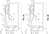
- a velocity profile of the air propelled by the fan rotor 60 to the primary flowpath 44 and the secondary flowpath 46 may be tuned to provide a maximum velocity region 94 (or point) radially at a splitter 96 between the primary flowpath inlet 48 and the secondary flowpath inlet 52.
- the velocity profile of the air propelled by the fan rotor 60 to the primary flowpath 44 and the secondary flowpath 46 may be tuned to provide the maximum velocity region 94 (or point) radially above the splitter 96; e.g., at or along the secondary flowpath inlet 52.
- the velocity profile is not limited to such exemplary locations.
- the turbine engine 22 may include a variable area nozzle 98 to further or alternatively adjust a pressure ratio and/or a velocity ratio between the primary flowpath air stream and the secondary flowpath air stream.
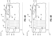
- the variable area nozzle 98 of FIGS. 4A and 4B is configured to form the secondary flowpath exhaust 54.
- the secondary flowpath 46 in particular, extends (e.g., axially) in the engine housing 36 / the turbine engine 22 to the variable area nozzle 98.
- the variable area nozzle 98 is configured to move between a restricted arrangement (e.g., see FIG. 4A ) and an unrestricted arrangement (e.g., see FIG. 4B ).
- a flow area through the variable area nozzle 98 / the secondary flowpath exhaust 54 has a restricted value.
- the flow area through the variable area nozzle 98 / the secondary flowpath exhaust 54 has an unrestricted value that is greater than the restricted value.
- variable area nozzle 98 decreases flow resistance through the secondary flowpath 46 and thereby effectively directs additional air propelled by the fan rotor 60 radially upward into the secondary flowpath 46.
- the variable area nozzle 98 therefore may be used to tune (e.g., increase or decrease) the pressure ratio and/or the velocity ratio between the primary flowpath air stream and the secondary flowpath air stream.
- the turbine engine 22 may include a variable vane arrangement 100 to further or alternatively adjust the pressure ratio and/or the velocity ratio between the primary flowpath air stream and the secondary flowpath air stream.
- the variable vane arrangement 100 of FIGS. 5A and 5B includes a plurality of inlet guide vanes 102 arranged circumferentially about the centerline axis 24 in an array. This array of the inlet guide vanes 102 is disposed within an inlet duct 104 of the turbine engine 22 upstream of the fan rotor 60.
- Each of the inlet guide vanes 102 projects radially inward (in a direction towards the centerline axis 24) to a respective distal end 106, where the distal end 106 may be radially aligned with or inward of the splitter 96.
- Each inlet guide vane 102 of FIGS. 5A and 5B may thereby radially overlap at least a portion of or an entirety of the secondary flowpath inlet 52.
- Each inlet guide vane 102 may also partially radially overlap a radial outer portion of the primary flowpath inlet 48.
- Each inlet guide vane 102 of FIG. 5A has a radially extending span 108.
- Each fan blade 92 has a radially extending span 110, where the blade span 110 is greater than the vane span 108.
- the blade span 110 may be at least two times (2x), three times (3x) or four times (4x) the vane span 108.
- each inlet guide vane 102 may be configured to move (e.g., pivot) about an axis between a first (e.g., open, unrestricted) position and a second (e.g., closed, restricted) position.
- a flow area through the variable vane arrangement 100 In the restricted position of FIGS. 5A and 6A , a flow area through the variable vane arrangement 100 has a restricted value.
- the flow area through the variable vane arrangement 100 has an unrestricted value that is greater than the restricted value.
- variable vane arrangement 100 increases flow resistance upstream of and along the secondary portion 90 of the fan rotor 60 thereby effectively directing additional air towards the primary portion 88 of the fan rotor 60 and, thus, the primary flowpath 44.
- variable vane arrangement 100 decreases flow resistance upstream of and along the secondary portion 90 of the fan rotor 60 thereby effectively directing additional air towards the secondary portion 90 of the fan rotor 60 and, thus, the secondary flowpath 46.
- the variable vane arrangement 100 therefore may be used to tune (e.g., increase or decrease) the pressure ratio and/or the velocity ratio between the primary flowpath air stream and the secondary flowpath air stream.
- each inlet guide vane 102 may also move to one or more intermediate positions (e.g., partially open / closed positions) between the first position and the second position.
- variable vane arrangement 100 is configured to guide flow into the secondary portion 90 of the fan rotor 60 and, thus, the secondary flowpath 46.
- the variable vane arrangement 100 may be configured to guide flow into the primary portion 88 and the secondary portion 90 of the fan rotor 60 and, thus, the primary flowpath 44 and the secondary flowpath 46.
- the blade span 110 of FIG. 7A may be equal to or within five or ten percent (5-10%) of the vane span 108.
- variable vane arrangement 100 may alternatively be configured to condition the air propelled by the fan rotor 60 towards the respective flowpath 44, 46.
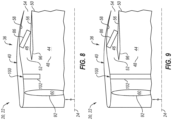
- the vanes 102 e.g., exit guide vanes
- the vanes 102 may be moved (e.g., see FIGS. 6A and 6B ) to tune (e.g., increase or decrease) the pressure ratio and/or the velocity ratio between the primary flowpath air stream and the secondary flowpath air stream.
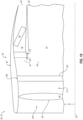
- the secondary flowpath 46 may also or alternatively be provided with a variable vane arrangement 112.
- This variable vane arrangement 112 may operate similar to the above variable vane arrangements 100 to tune (e.g., increase or decrease) the pressure ratio and/or the velocity ratio between the primary flowpath air stream and the secondary flowpath air stream.
- the variable vane arrangement of FIG. 10 is arranged within the secondary flowpath 46 upstream of the heat exchanger 86.
- the variable vane arrangement 112 of FIG. 10 for example, is disposed at (e.g., on, adjacent or proximate) the secondary flowpath inlet 52.
- each actuatable apparatus e.g., 98, 100, 112 and/or one or more of its elements may be respectively actuated by an actuation system 116 controlled by an electronic controller 118.
- This controller 118 is configured to provide a control signal to the actuation system 116 to move the actuatable apparatus between various arrangements (e.g., the restricted and unrestricted arrangement) to tune the pressure ratio and/or the velocity ratio between the primary flowpath air stream and the secondary flowpath air stream as described above.
- the controller 118 may provide this control signal based on one or more operational parameters. Examples of these operational parameters include, but are not limited to, a heat load to be rejected by the heat exchanger 86, an engine power setting, ambient conditions, etc.
- the controller 118 may estimate a heat transfer parameter, and signal the actuation system 116 to adjust the actuatable apparatus to affect boundary conditions of the heat exchanger 86 to achieve the heat transfer parameter.
- the secondary flowpath 46 may be located radially outboard of, extend axially along (e.g., axially overlap) and/or extend circumferentially about (e.g., circumscribe) the primary flowpath 44.
- the primary flowpath 44 may alternatively be located radially outboard of, extend axially along (e.g., axially overlap) and/or extend circumferentially about (e.g., circumscribe) the secondary flowpath 46.
- the primary flowpath 44 and the secondary flowpath 46 may each be disposed in / extend in the aircraft propulsion system 20 and its turbine engine 22 / its engine housing 36.
- the primary flowpath 44 may alternatively be disposed (e.g., radially) outside of the aircraft propulsion system 20 and its turbine engine 22 / its engine housing 36.
- the turbine engine 22, for example, may alternatively be configured as an open rotor engine.
- the rotor 60 is configured as an open (e.g., un-ducted) propulsor rotor and the blades 92 are configured as open (e.g., un-ducted) blades.
- the fan rotor 60 may be configured with a variable fan pressure ratio as described above. This may be provided in addition to the various other techniques for tuning the pressure ratio and/or the velocity ratio between the primary flowpath air stream and the secondary flowpath air stream; e.g., see FIGS. 4A, 4B , 5A, 5B , 7A, 7B and 8-10 .
- the fan rotor 60 (or open rotor) may be configured with a (e.g., substantially) uniform fan pressure ratio.
- the various other techniques may be (e.g., solely) used for tuning the pressure ratio and/or the velocity ratio between the primary flowpath air stream and the secondary flowpath air stream; e.g., see FIGS. 4A, 4B , 5A, 5B , 7A, 7B and 8-10 .
- vanes e.g., 102 in the variable vane arrangements (e.g., 100, 112) described above are variable vanes
- the present invention is not limited to such an exemplary arrangement.
- One or more of the vanes may alternatively be configured as a fixed vane. With such an arrangement, a pressure ratio across the vane arrangement may be tuned similar to the variable fan pressure ratio described above.
- the aircraft propulsion system 20 may include various turbine engines other than the one described above.
- the aircraft propulsion system 20, for example, may include a geared turbine engine where a geartrain connects one or more shafts to one or more rotors in a fan section, a compressor section and/or any other engine section.
- the aircraft propulsion system 20 may include a turbine engine configured without a geartrain; e.g., a direct drive turbine engine.
- the turbine engine may be configured with a single spool, with two spools (e.g., see FIG. 1 ), or with more than two spools.
- the turbine engine may be configured as a turbofan engine, a turbojet engine, a turboprop engine, a turboshaft engine, a propfan engine, a pusher fan engine or any other type of turbine engine.
- the present invention therefore is not limited to any particular types or configurations of turbine engines.
Landscapes
- Engineering & Computer Science (AREA)
- Chemical & Material Sciences (AREA)
- Combustion & Propulsion (AREA)
- Mechanical Engineering (AREA)
- General Engineering & Computer Science (AREA)
- Physics & Mathematics (AREA)
- Geometry (AREA)
- Structures Of Non-Positive Displacement Pumps (AREA)
Abstract
An aircraft propulsion system (20) includes a turbine engine (22) having a propulsor rotor (60), an engine core (42) and a heat exchanger (86). The propulsor rotor (60) is configured to rotate about an axis (24) and direct a first air stream along a primary flowpath (44) that bypasses the engine core (42) and direct a second air stream along a secondary flowpath (46) with a geometry extending at least eighty degrees about the axis (24). The turbine engine (22) is configured such that the first air stream enters the primary flowpath (44) at a first pressure and the second air stream enters the secondary flowpath (46) at a second pressure that is different than the first pressure. The engine core (42) is configured to drive rotation of the propulsor rotor (60). The heat exchanger (86) is disposed within the secondary flowpath (46).
Description
- This invention relates generally to a turbine engine and, more particularly, to arranging a heat exchanger within the turbine engine.
- A gas turbine engine may include one or more heat exchangers for cooling various working fluids. Various heat exchanger arrangements and locations are known in the art. While these known heat exchanger arrangements and locations have various benefits, there is still room in the art for improvement.
- According to an aspect of the present invention, a propulsion system is provided for an aircraft. This propulsion system includes a turbine engine, and the turbine engine includes a propulsor rotor, an engine core and a heat exchanger. The propulsor rotor is configured to rotate about an axis and direct a first air stream along a primary flowpath that bypasses the engine core. The propulsor rotor is configured to direct a second air stream along a secondary flowpath with a geometry extending at least eighty degrees about the axis. The turbine engine is configured such that the first air stream enters the primary flowpath at a first pressure and the second air stream enters the secondary flowpath at a second pressure that is different than the first pressure. The engine core is configured to drive rotation of the propulsor rotor. The heat exchanger is disposed within the secondary flowpath.
- According to another aspect of the present invention, another propulsion system is provided for an aircraft. This propulsion system includes a turbine engine, and the turbine engine includes a propulsor rotor, a variable area nozzle, an engine core and a heat exchanger. The propulsor rotor is configured to direct a first air stream along a primary flowpath that bypasses the engine core. The propulsor rotor is configured to direct a second air stream along a secondary flowpath that bypasses the engine core. The secondary flowpath extends in the turbine engine to the variable area nozzle. The variable area nozzle is configured to change a pressure ratio between a first pressure of the first air stream entering the primary flowpath to a second pressure of the second air stream entering the secondary flowpath. The turbine engine is configured to drive rotation of the propulsor rotor. The heat exchanger is disposed within the secondary flowpath upstream of the variable area nozzle.
- According to still another aspect of the present invention, another propulsion system is provided for an aircraft. This propulsion system includes a turbine engine, and the turbine engine includes a propulsor rotor, a variable vane arrangement, an engine core and a heat exchanger. The propulsor rotor is configured to direct a first air stream along a primary flowpath that bypasses the engine core. The propulsor rotor is configured to direct a second air stream along a secondary flowpath that bypasses the engine core. The variable vane arrangement is configured to change a pressure ratio between a first pressure of the first air stream entering the primary flowpath to a second pressure of the second air stream entering the secondary flowpath. The turbine engine is configured to drive rotation of the propulsor rotor. The heat exchanger is disposed within the secondary flowpath.
- The following optional features may be applied to any of the above aspects.
- The secondary flowpath may extend at least eighty degrees circumferentially about the axis.
- The secondary flowpath may bypass the engine core.
- An entrance to the primary flowpath and an entrance to the secondary flowpath may be axially aligned along the axis.
- The primary flowpath and the secondary flowpath may each extend in the turbine engine.
- The primary flowpath may extend outside of the turbine engine. The secondary flowpath may extend in the turbine engine.
- The secondary flowpath may be radially outboard of and extend circumferentially about the primary flowpath.
- The primary flowpath may be radially outboard of and extend circumferentially about the secondary flowpath.
- The second pressure may be greater than the first pressure.
- The turbine engine may be configured such that the first air stream enters the primary flowpath at a first velocity and the second air stream enters the secondary flowpath at a second velocity that is greater than the first velocity.
- A first radial portion of the propulsor rotor may be configured to provide a first pressure ratio across the propulsor rotor. The first radial portion of the propulsor rotor may be configured to direct the first air stream into the primary flowpath. A second radial portion of the propulsor rotor may be configured to provide a second pressure ratio across the propulsor rotor that is different than the first pressure ratio. The second radial portion of the propulsor rotor may be configured to direct the second air stream into the secondary flowpath.
- The turbine engine may also include a variable area nozzle. The secondary flowpath may extend in the turbine engine to the variable area nozzle. Movement of the variable area nozzle may change a ratio between the first pressure and the second pressure.
- The turbine engine may also include a plurality of guide vanes arranged circumferentially about the axis in an array. The guide vanes may be upstream of the propulsor rotor. The guide vanes may be configured to guide air to at least a radial portion of the propulsor rotor that directs the second air stream into the secondary flowpath.
- A first of the guide vanes may have a vane span. The propulsor rotor may include a propulsor blade with a blade span that is at least two times larger than the vane span.
- The guide vanes may also be configured to guide the air to a radial portion of the propulsor rotor that directs the first air stream into the primary flowpath.
- A first of the guide vanes may be a first variable vane. Movement of the first variable vane may change a ratio between the first pressure and the second pressure.
- The turbine engine may also include a plurality of guide vanes arranged circumferentially about the axis in an array. The guide vanes may be downstream of the propulsor rotor. The guide vanes may be configured to guide the first air stream into the primary flowpath. The guide vanes may be configured to guide the second air stream into the secondary flowpath.
- A first of the guide vanes may be a first variable vane. Movement of the first variable vane may change a ratio between the first pressure and the second pressure.
- The turbine engine may also include a plurality of guide vanes arranged circumferentially about the axis in an array. The guide vanes may be disposed within the secondary flowpath upstream of the heat exchanger.
- The present invention may include any one or more of the individual features disclosed above and/or below alone or in any combination thereof.
- The foregoing features and the operation of the invention will become more apparent in light of the following description and the accompanying drawings.
-
-
FIG. 1 is a partial schematic illustration of a propulsion system for an aircraft. -
FIG. 2 is a schematic illustration of a portion of the propulsion system with a primary flowpath and a secondary flowpath. -
FIGS. 3A and 3B are schematic illustrations of a portion of the propulsion system with various flow velocity profiles. -
FIGS. 4A and 4B are schematic illustrations of a portion of the propulsion system with a variable area nozzle in various positions. -
FIGS. 5A and 5B are schematic illustrations of a portion of the propulsion system with a variable vane arrangement in various positions. -
FIGS. 6A and 6B are schematic illustrations of a portion of the variable vane arrangement with its vanes in various positions. -
FIGS. 7A and 7B are schematic illustrations of a portion of the propulsion system with another variable vane arrangement in various positions. -
FIGS. 8-10 are schematic illustrations of a portion of the propulsion system with other variable vane arrangements. -
FIG. 11 is a schematic illustration of an actuatable apparatus of the propulsion system arranged with an actuation system and a controller. -
FIGS. 12 and13 are partial schematic illustrations of the propulsion system with various alternative primary and secondary flowpath arrangements. -
FIG. 1 illustrates a propulsion system 20 for an aircraft. The aircraft may be an airplane, a drone (e.g., an unmanned aerial vehicle (UAV)) or any other manned or unmanned aerial vehicle. The aircraft propulsion system 20 ofFIG. 1 includes a gas turbine engine 22 such as, but not limited to, a turbofan engine. - The turbine engine 22 extends axially along a
centerline axis 24 between a forward,upstream end 26 of the turbine engine 22 and an aft,downstream end 28 of the turbine engine 22. The turbine engine 22 includes afan section 30, acompressor section 31, acombustor section 32 and aturbine section 33. Thecompressor section 31 ofFIG. 1 includes a low pressure compressor (LPC)section 31A and a high pressure compressor (HPC)section 31B. Theturbine section 33 ofFIG. 1 includes a high pressure turbine (HPT)section 33A and a low pressure turbine (LPT)section 33B. - The engine sections 30-33B of
FIG. 1 are arranged sequentially along thecenterline axis 24 within anengine housing 36. Thisengine housing 36 includes an inner housing structure 38 ("inner structure") and an outer housing structure 40 ("outer structure"). Theinner structure 38 and/or theouter structure 40 may each include one or more engine cases and/or a nacelle structure, which nacelle structure may provide an aerodynamic covering for / over the respective engine case(s). Briefly, theinner structure 38 ofFIG. 1 houses one or more of theengine sections 31A-33B, whichengine sections 31A-33B may form / are included in acore 42 of the turbine engine 22. Theouter structure 40 ofFIG. 1 houses at least thefan section 30. Thisouter structure 40 is also disposed radially outboard of, extends circumferentially about (e.g., circumscribes) and extends axially along (e.g., overlaps) at least a forward portion of theinner structure 38. - The
engine housing 36 may provide the aircraft propulsion system 20 with a bifurcated (e.g., bypass) flow. Theengine housing 36 ofFIG. 1 , for example, at least partially or completely forms aprimary flowpath 44 and asecondary flowpath 46 of the aircraft propulsion system 20 and its turbine engine 22. Theprimary flowpath 44 may be configured as an inner bypass flowpath. Thesecondary flowpath 46 may be configured as an outer bypass flowpath disposed radially outboard of theprimary flowpath 44. The present invention, however, is not limited to such an exemplary primary and secondary flowpath arrangement as described below in further detail. - The
primary flowpath 44 ofFIG. 1 is disposed radially outboard of and is configured to bypass the (e.g., entire)engine core 42. Thisprimary flowpath 44, for example, extends axially along thecenterline axis 24 within theengine housing 36 from a forward, upstream inlet 48 (e.g., an entrance) into theprimary flowpath 44 to an aft,downstream exhaust 50 from theprimary flowpath 44. Theprimary flowpath 44 extends radially within theengine housing 36 from theinner structure 38 to theouter structure 40. Theprimary flowpath 44 may thereby be formed by and radially between theinner structure 38 and theouter structure 40. Theprimary flowpath 44 extends circumferentially within theengine housing 36 about (e.g., completely around) thecenterline axis 24. With such an arrangement, theprimary flowpath 44 may have a full-hoop (e.g., annular) geometry. Theprimary flowpath 44, of course, may (or may not) be circumferentially interrupted by one or more vanes, one or more struts, one or more bifurcations and/or one or more other such structures extending between theinner structure 38 and theouter structure 40. - The
secondary flowpath 46 ofFIG. 1 is disposed radially outboard of and is configured to bypass the (e.g., entire)engine core 42. Thesecondary flowpath 46 ofFIG. 1 is also configured to bypass at least a portion or an entirety of theprimary flowpath 44. Thissecondary flowpath 46, for example, extends axially along thecenterline axis 24 within theengine housing 36 from a forward, upstream inlet 52 (e.g., an entrance) into thesecondary flowpath 46 to an aft,downstream exhaust 54 from thesecondary flowpath 46. Thesecondary flowpath inlet 52 may be axially aligned with theprimary flowpath inlet 48 along thecenterline axis 24. Thesecondary flowpath exhaust 54 may be axially aligned with (or alternatively forward or aft of) theprimary flowpath exhaust 50 along thecenterline axis 24. Thesecondary flowpath 46 extends radially within theouter structure 40. Thesecondary flowpath 46 ofFIG. 1 , for example, extends radially from a ductinner wall 56 of theouter structure 40 to a ductouter wall 58 of theouter structure 40. Thesecondary flowpath 46 extends circumferentially within theouter structure 40 about (e.g., completely around) thecenterline axis 24. With such an arrangement, thesecondary flowpath 46 may have a full-hoop (e.g., annular) geometry. Thesecondary flowpath 46, of course, may (or may not) be circumferentially interrupted by one or more vanes, one or more struts, one or more bifurcations and/or one or more other such structures extending between theinner wall 56 and theouter wall 58. Alternatively, thesecondary flowpath 46 may extend circumferentially within theouter structure 40 partially about thecenterline axis 24, for example at least eighty degrees (80°). For example, thesecondary flowpath 46 may extend between one-hundred degrees (100°) and one-hundred and twenty degrees (120°), or between one-hundred degrees and twenty (120°) and one-hundred and seventy degrees (170°). With such an arrangement, theouter structure 40 may include multiple of thesecondary flowpaths 46 arranged about thecenterline axis 24. - Each of the
engine sections - The
fan rotor 60 is connected to ageartrain 66, for example, through afan shaft 68. Thegeartrain 66 and theLPC rotor 61 are connected to and driven by theLPT rotor 64 through alow speed shaft 69. TheHPC rotor 62 is connected to and driven by theHPT rotor 63 through ahigh speed shaft 70. The engine shafts 68-70 are rotatably supported by a plurality of bearings; e.g., rolling element and/or thrust bearings. Each of these bearings is connected to theengine housing 36 by at least one stationary structure such as, for example, an annular support strut. - During operation, air enters the aircraft propulsion system 20 and its turbine engine 22 through an
airflow inlet 72 into the turbine engine 22. This air is directed through thefan section 30 and into acore flowpath 74, theprimary flowpath 44 and thesecondary flowpath 46. The core flowpath 74 ofFIG. 1 extends through theengine core 42 and sequentially through itsengine sections 31A-33B from a forward,upstream inlet 76 into thecore flowpath 74 to an aft,downstream exhaust 78 from thecore flowpath 74. Briefly, thecore flowpath inlet 76 may be axially aligned with theprimary flowpath inlet 48 and/or thesecondary flowpath inlet 52 along thecenterline axis 24. Thecore flowpath exhaust 78 may be axially aft of theprimary flowpath inlet 48 and/or thesecondary flowpath inlet 52 along thecenterline axis 24; however, the present invention is not limited to such an exemplary arrangement. The air entering thecore flowpath 74 may be referred to as "core air". The air entering theprimary flowpath 44 may be referred to as "primary flowpath air", or "primary bypass air". The air entering thesecondary flowpath 46 may be referred to as "secondary flowpath air", or "secondary bypass air". - The core air is compressed by the
LPC rotor 61 and theHPC rotor 62 and directed into a (e.g., annular)combustion chamber 80 of a (e.g., annular)combustor 82 in thecombustor section 32. Fuel is injected by one ormore fuel injectors 84 into thecombustion chamber 80 and mixed with the compressed core air to provide a fuel-air mixture. This fuel-air mixture is ignited and combustion products thereof flow through and sequentially cause theHPT rotor 63 and theLPT rotor 64 to rotate before being directed out of the aircraft propulsion system 20 and its turbine engine 22 through thecore flowpath exhaust 78. The rotation of theHPT rotor 63 and theLPT rotor 64 respectively drive rotation of theHPC rotor 62 and theLPC rotor 61 and, thus, compression of the core air received from thecore flowpath inlet 76. The rotation of theLPT rotor 64 also drives rotation of thefan rotor 60. The rotation of thefan rotor 60 propels a stream of the primary flowpath air through theprimary flowpath 44 and out of the aircraft propulsion system 20 and its turbine engine 22 through theprimary flowpath exhaust 50. The propulsion of the primary flowpath air may account for a majority of thrust generated by the aircraft propulsion system 20 and its turbine engine 22. The rotation of thefan rotor 60 also propels a stream of the secondary flowpath air through thesecondary flowpath 46 and out of the aircraft propulsion system 20 and its turbine engine 22 through thesecondary flowpath exhaust 54. - The turbine engine 22 of
FIG. 1 also includes aheat exchanger 86 for cooling a working fluid of the turbine engine 22. Examples of the working fluid include, but are not limited to, lubricant (e.g., engine oil), coolant, another airflow or fuel. Theheat exchanger 86 is arranged within thesecondary flowpath 46. Theheat exchanger 86 ofFIG. 1 , for example, is disposed at an intermediate location axially along thesecondary flowpath 46 between thesecondary flowpath inlet 52 and thesecondary flowpath exhaust 54. Thisheat exchanger 86 extends radially across thesecondary flowpath 46, for example, radially between and to theinner wall 56 and theouter wall 58. With this arrangement, at least some or all of the stream of the secondary flowpath air flows through theheat exchanger 86 as that air is directed from thesecondary flowpath inlet 52 to thesecondary flowpath exhaust 54. As the secondary flowpath air crosses theheat exchanger 86, theheat exchanger 86 transfers heat energy between the working fluid and the secondary flowpath air. Thus, where the secondary flowpath air is cooler than the working fluid, theheat exchanger 86 may cool the working fluid. - The
heat exchanger 86 may extend circumferentially about thecenterline axis 24 within thesecondary flowpath 46. Theheat exchanger 86, for example, may be configured with a full-hoop (e.g., annular) geometry or alternatively an arcuate geometry. Theheat exchanger 86 may be formed from a plurality of heat exchanger sections. These heat exchanger sections may be arranged circumferentially end-to-end (or slightly spaced) within thesecondary flowpath 46. The present invention, however, is not limited to such an exemplary heat exchanger arrangement. - A temperature differential between a temperature of the secondary flowpath air and a temperature of the working fluid may change based on various parameters including, but not limited to, operating conditions (e.g., aircraft altitude, ambient temperature, etc.) and/or engine power setting. In some circumstances, this temperature differential may be relatively small. During such circumstances, there is a benefit to directing the stream of the secondary flowpath air into the
secondary flowpath 46 at a relatively high pressure and/or a relatively high velocity. However, increasing a pressure and/or a velocity of the stream of the primary flowpath air may decrease propulsion efficiency of the aircraft propulsion system 20 and its turbine engine 22. Therefore, referring toFIG. 2 , the turbine engine 22 of the present invention is configured such that (A) the stream of the primary flowpath air entering theprimary flowpath 44 is at a primary flowpath pressure and a (e.g., average) primary flowpath velocity and (B) the stream of the secondary flowpath air entering thesecondary flowpath 46 is at a secondary flowpath pressure and a (e.g., average) primary flowpath velocity, where the primary flowpath pressure is different (e.g., less) than the secondary flowpath pressure and the primary flowpath velocity is different (e.g., less) than the secondary flowpath velocity during at least one mode of operation (or during all modes of operation). - To facilitate the pressure and/or velocity differential between the
primary flowpath 44 and thesecondary flowpath 46, thefan rotor 60 may be configured with a variable fan pressure ratio. A primary (e.g., inner and/or intermediate)portion 88 of thefan rotor 60 ofFIG. 2 , for example, is configured to provide a first pressure ratio across thefan rotor 60. Thisprimary portion 88 of thefan rotor 60 is configured to direct the stream of the primary flowpath air into theprimary flowpath 44 with a first velocity profile. A secondary (e.g., outer)portion 90 of thefan rotor 60 ofFIG. 2 , on the other hand, is configured to provide a second pressure ratio across thefan rotor 60. Thissecondary portion 90 of thefan rotor 60 is configured to direct the stream of the secondary flowpath air into thesecondary flowpath 46 with a second velocity profile that is different (e.g., greater) than the first velocity profile. Thefan rotor 60 may thereby be tailored to direct air into thesecondary flowpath 46 at a different (e.g., higher) pressure and/or velocity than air directed into theprimary flowpath 44. Various blade parameters of thefan rotor 60 may be tuned (e.g., varied) to provide thefan rotor 60 with its multi-pressure ratio configuration. Examples of these blade parameters include, but are not limited to, a blade exit metal angle (or a blade exit angle) of eachfan blade 92 and/or twist of eachfan blade 92. For example, the blade exit metal angle and/or the fan blade twist may be varied (e.g., increased) at or near thesecondary portion 90 of thefan rotor 60. - In some embodiments, referring to
FIG. 3A , a velocity profile of the air propelled by thefan rotor 60 to theprimary flowpath 44 and thesecondary flowpath 46 may be tuned to provide a maximum velocity region 94 (or point) radially at asplitter 96 between theprimary flowpath inlet 48 and thesecondary flowpath inlet 52. In other embodiments, referring toFIG. 3B , the velocity profile of the air propelled by thefan rotor 60 to theprimary flowpath 44 and thesecondary flowpath 46 may be tuned to provide the maximum velocity region 94 (or point) radially above thesplitter 96; e.g., at or along thesecondary flowpath inlet 52. The velocity profile, however, is not limited to such exemplary locations. - In some embodiments, referring to
FIG. 4A and 4B , the turbine engine 22 may include avariable area nozzle 98 to further or alternatively adjust a pressure ratio and/or a velocity ratio between the primary flowpath air stream and the secondary flowpath air stream. Thevariable area nozzle 98 ofFIGS. 4A and 4B , for example, is configured to form thesecondary flowpath exhaust 54. Thesecondary flowpath 46, in particular, extends (e.g., axially) in theengine housing 36 / the turbine engine 22 to thevariable area nozzle 98. Thevariable area nozzle 98 is configured to move between a restricted arrangement (e.g., seeFIG. 4A ) and an unrestricted arrangement (e.g., seeFIG. 4B ). In the restricted arrangement ofFIG. 4A , a flow area through thevariable area nozzle 98 / thesecondary flowpath exhaust 54 has a restricted value. In the unrestricted arrangement ofFIG. 4B , the flow area through thevariable area nozzle 98 / thesecondary flowpath exhaust 54 has an unrestricted value that is greater than the restricted value. By restricting the flow area (seeFIG. 4A ), thevariable area nozzle 98 increases flow resistance through thesecondary flowpath 46 and thereby effectively directs additional air propelled by thefan rotor 60 radially downward into theprimary flowpath 44. However, by unrestricting the flow area (seeFIG. 4B ), thevariable area nozzle 98 decreases flow resistance through thesecondary flowpath 46 and thereby effectively directs additional air propelled by thefan rotor 60 radially upward into thesecondary flowpath 46. Thevariable area nozzle 98 therefore may be used to tune (e.g., increase or decrease) the pressure ratio and/or the velocity ratio between the primary flowpath air stream and the secondary flowpath air stream. - In some embodiments, referring to
FIGS. 5A and 5B , the turbine engine 22 may include avariable vane arrangement 100 to further or alternatively adjust the pressure ratio and/or the velocity ratio between the primary flowpath air stream and the secondary flowpath air stream. Thevariable vane arrangement 100 ofFIGS. 5A and 5B , for example, includes a plurality ofinlet guide vanes 102 arranged circumferentially about thecenterline axis 24 in an array. This array of theinlet guide vanes 102 is disposed within aninlet duct 104 of the turbine engine 22 upstream of thefan rotor 60. Each of theinlet guide vanes 102 projects radially inward (in a direction towards the centerline axis 24) to a respectivedistal end 106, where thedistal end 106 may be radially aligned with or inward of thesplitter 96. Eachinlet guide vane 102 ofFIGS. 5A and 5B may thereby radially overlap at least a portion of or an entirety of thesecondary flowpath inlet 52. Eachinlet guide vane 102 may also partially radially overlap a radial outer portion of theprimary flowpath inlet 48. Eachinlet guide vane 102 ofFIG. 5A has aradially extending span 108. Eachfan blade 92 has aradially extending span 110, where theblade span 110 is greater than thevane span 108. Theblade span 110, for example, may be at least two times (2x), three times (3x) or four times (4x) thevane span 108. - Referring to
FIGS. 6A and 6B , eachinlet guide vane 102 may be configured to move (e.g., pivot) about an axis between a first (e.g., open, unrestricted) position and a second (e.g., closed, restricted) position. In the restricted position ofFIGS. 5A and6A , a flow area through thevariable vane arrangement 100 has a restricted value. In the unrestricted arrangement ofFIGS. 5B and6B , the flow area through thevariable vane arrangement 100 has an unrestricted value that is greater than the restricted value. By restricting the flow area (seeFIGS. 5A and6A ), thevariable vane arrangement 100 increases flow resistance upstream of and along thesecondary portion 90 of thefan rotor 60 thereby effectively directing additional air towards theprimary portion 88 of thefan rotor 60 and, thus, theprimary flowpath 44. However, by unrestricting the flow area (seeFIGS. 5B and6B ), thevariable vane arrangement 100 decreases flow resistance upstream of and along thesecondary portion 90 of thefan rotor 60 thereby effectively directing additional air towards thesecondary portion 90 of thefan rotor 60 and, thus, thesecondary flowpath 46. Thevariable vane arrangement 100 therefore may be used to tune (e.g., increase or decrease) the pressure ratio and/or the velocity ratio between the primary flowpath air stream and the secondary flowpath air stream. Of course, it is contemplated eachinlet guide vane 102 may also move to one or more intermediate positions (e.g., partially open / closed positions) between the first position and the second position. - In the embodiment of
FIGS. 5A and 5B , thevariable vane arrangement 100 is configured to guide flow into thesecondary portion 90 of thefan rotor 60 and, thus, thesecondary flowpath 46. In other embodiments however, referring toFIGS. 7A and 7B , thevariable vane arrangement 100 may be configured to guide flow into theprimary portion 88 and thesecondary portion 90 of thefan rotor 60 and, thus, theprimary flowpath 44 and thesecondary flowpath 46. Theblade span 110 ofFIG. 7A , for example, may be equal to or within five or ten percent (5-10%) of thevane span 108. Moreover, while thevariable vane arrangement 100 ofFIGS. 5A and 5B ,7A and 7B are positioned upstream of thefan rotor 60, a similar arrangement may be provided downstream of thefan rotor 60 and upstream of thesecondary flowpath inlet 52. For example, referring toFIGS. 8 and 9 , thevariable vane arrangement 100 may alternatively be configured to condition the air propelled by thefan rotor 60 towards therespective flowpath FIGS. 6A and 6B ) to tune (e.g., increase or decrease) the pressure ratio and/or the velocity ratio between the primary flowpath air stream and the secondary flowpath air stream. - In some embodiments, referring to
FIG. 10 , thesecondary flowpath 46 may also or alternatively be provided with avariable vane arrangement 112. Thisvariable vane arrangement 112 may operate similar to the abovevariable vane arrangements 100 to tune (e.g., increase or decrease) the pressure ratio and/or the velocity ratio between the primary flowpath air stream and the secondary flowpath air stream. However, rather than being arranged in theinlet duct 104 or afan duct 113, the variable vane arrangement ofFIG. 10 is arranged within thesecondary flowpath 46 upstream of theheat exchanger 86. Thevariable vane arrangement 112 ofFIG. 10 , for example, is disposed at (e.g., on, adjacent or proximate) thesecondary flowpath inlet 52. - Referring to
FIG. 11 , each actuatable apparatus (e.g., 98, 100, 112) and/or one or more of its elements may be respectively actuated by anactuation system 116 controlled by anelectronic controller 118. Thiscontroller 118 is configured to provide a control signal to theactuation system 116 to move the actuatable apparatus between various arrangements (e.g., the restricted and unrestricted arrangement) to tune the pressure ratio and/or the velocity ratio between the primary flowpath air stream and the secondary flowpath air stream as described above. Thecontroller 118 may provide this control signal based on one or more operational parameters. Examples of these operational parameters include, but are not limited to, a heat load to be rejected by theheat exchanger 86, an engine power setting, ambient conditions, etc. For example, thecontroller 118 may estimate a heat transfer parameter, and signal theactuation system 116 to adjust the actuatable apparatus to affect boundary conditions of theheat exchanger 86 to achieve the heat transfer parameter. - In some embodiments, referring to
FIG. 1 , thesecondary flowpath 46 may be located radially outboard of, extend axially along (e.g., axially overlap) and/or extend circumferentially about (e.g., circumscribe) theprimary flowpath 44. In other embodiments, referring toFIGS. 12 and13 , theprimary flowpath 44 may alternatively be located radially outboard of, extend axially along (e.g., axially overlap) and/or extend circumferentially about (e.g., circumscribe) thesecondary flowpath 46. - In some embodiments, referring to
FIGS. 1 and12 , theprimary flowpath 44 and thesecondary flowpath 46 may each be disposed in / extend in the aircraft propulsion system 20 and its turbine engine 22 / itsengine housing 36. In other embodiments, referring toFIG. 13 , theprimary flowpath 44 may alternatively be disposed (e.g., radially) outside of the aircraft propulsion system 20 and its turbine engine 22 / itsengine housing 36. The turbine engine 22, for example, may alternatively be configured as an open rotor engine. Here, therotor 60 is configured as an open (e.g., un-ducted) propulsor rotor and theblades 92 are configured as open (e.g., un-ducted) blades. - In some embodiments, the
fan rotor 60 may be configured with a variable fan pressure ratio as described above. This may be provided in addition to the various other techniques for tuning the pressure ratio and/or the velocity ratio between the primary flowpath air stream and the secondary flowpath air stream; e.g., seeFIGS. 4A, 4B ,5A, 5B ,7A, 7B and8-10 . In other embodiments, the fan rotor 60 (or open rotor) may be configured with a (e.g., substantially) uniform fan pressure ratio. In such embodiments, the various other techniques may be (e.g., solely) used for tuning the pressure ratio and/or the velocity ratio between the primary flowpath air stream and the secondary flowpath air stream; e.g., seeFIGS. 4A, 4B ,5A, 5B ,7A, 7B and8-10 . - While the vanes (e.g., 102) in the variable vane arrangements (e.g., 100, 112) described above are variable vanes, the present invention is not limited to such an exemplary arrangement. One or more of the vanes, for example, may alternatively be configured as a fixed vane. With such an arrangement, a pressure ratio across the vane arrangement may be tuned similar to the variable fan pressure ratio described above.
- The aircraft propulsion system 20 may include various turbine engines other than the one described above. The aircraft propulsion system 20, for example, may include a geared turbine engine where a geartrain connects one or more shafts to one or more rotors in a fan section, a compressor section and/or any other engine section. Alternatively, the aircraft propulsion system 20 may include a turbine engine configured without a geartrain; e.g., a direct drive turbine engine. The turbine engine may be configured with a single spool, with two spools (e.g., see
FIG. 1 ), or with more than two spools. The turbine engine may be configured as a turbofan engine, a turbojet engine, a turboprop engine, a turboshaft engine, a propfan engine, a pusher fan engine or any other type of turbine engine. The present invention therefore is not limited to any particular types or configurations of turbine engines. - While various embodiments of the present invention have been described, it will be apparent to those of ordinary skill in the art that many more embodiments and implementations are possible within the scope of the invention. For example, the present invention as described herein includes several aspects and embodiments that include particular features. Although these features may be described individually, it is within the scope of the present invention that some or all of these features may be combined with any one of the aspects and remain within the scope of the invention. Accordingly, the present invention is not to be restricted except in light of the attached claims and their equivalents.
Claims (15)
- A propulsion system (20) for an aircraft, the propulsion system comprising a turbine engine (22) including a propulsor rotor (60), an engine core (42) and a heat exchanger (86),wherein the propulsor rotor (60) is configured to rotate about an axis (24) and direct a first air stream along a primary flowpath (44) that bypasses the engine core (42), and the propulsor rotor (60) is configured to direct a second air stream along a secondary flowpath (46) with a geometry extending at least eighty degrees about the axis, wherein the turbine engine (22) is configured such that the first air stream enters the primary flowpath (44) at a first pressure and the second air stream enters the secondary flowpath (46) at a second pressure that is different than the first pressure;wherein the engine core (42) is configured to drive rotation of the propulsor rotor (60); andwherein the heat exchanger (86) is disposed within the secondary flowpath (46).
- The propulsion system (20) of claim 1, wherein the secondary flowpath (46) bypasses the engine core (42).
- The propulsion system (20) of claim 1 or 2, wherein an entrance (48) to the primary flowpath (44) and an entrance (52) to the secondary flowpath (46) are axially aligned along the axis (24).
- The propulsion system (20) of any preceding claim, wherein the primary flowpath (44) and the secondary flowpath (46) each extend in the turbine engine (22).
- The propulsion system (20) of any of claims 1 to 3, wherein:the primary flowpath (44) extends outside of the turbine engine (22); andthe secondary flowpath (46) extends in the turbine engine (22).
- The propulsion system (20) of any preceding claim, wherein the primary flowpath (44) is radially outboard of and extends circumferentially about the secondary flowpath (46).
- The propulsion system (20) of any of claims 1 to 4, wherein the secondary flowpath (46) is radially outboard of and extends circumferentially about the primary flowpath (44).
- The propulsion system (20) of any preceding claim, wherein:the second pressure is greater than the first pressure; and/orthe turbine engine (22) is configured such that the first air stream enters the primary flowpath (44) at a first velocity and the second air stream enters the secondary flowpath (46) at a second velocity that is greater than the first velocity.
- The propulsion system (20) of any preceding claim, wherein:a first radial portion (88) of the propulsor rotor (60) is configured to provide a first pressure ratio across the propulsor rotor (60), and the first radial portion (88; 90) of the propulsor rotor (60) is configured to direct the first air stream into the primary flowpath (44); anda second radial portion (90) of the propulsor rotor (60) is configured to provide a second pressure ratio across the propulsor rotor (60) that is different than the first pressure ratio, and the second radial portion (90) of the propulsor rotor (60) is configured to direct the second air stream into the secondary flowpath (46).
- The propulsion system (20) of any preceding claim, wherein:the turbine engine (22) further includes a variable area nozzle (98);the secondary flowpath (46) extends in the turbine engine (22) to the variable area nozzle (98); andmovement of the variable area nozzle (98) changes a ratio between the first pressure and the second pressure.
- The propulsion system (20) of any preceding claim, wherein:the turbine engine (22) further includes a plurality of first guide vanes (102) arranged circumferentially about the axis (24) in an array;the plurality of first guide vanes (102) are upstream of the propulsor rotor (60); andthe plurality of first guide vanes (102) are configured to guide air to at least a or the second radial portion (90) of the propulsor rotor (60) that directs the second air stream into the secondary flowpath (46).
- The propulsion system (20) of claim 11, wherein:one of the plurality of first guide vanes (102) has a vane span (108) and the propulsor rotor (60) comprises a propulsor blade (92) with a blade span (110) that is at least twice as large as the vane span (108); and/orthe plurality of first guide vanes (102) are further configured to guide the air to a or the first radial portion (88) of the propulsor rotor (60) that directs the first air stream into the primary flowpath (44).
- The propulsion system (20) of any of claims 1 to 10, wherein:the turbine engine (22) further includes a plurality of first guide vanes (102) arranged circumferentially about the axis (24) in an array;the plurality of first guide vanes (102) are downstream of the propulsor rotor (60);the plurality of first guide vanes (102) are configured to guide the first air stream into the primary flowpath (44); andthe plurality of first guide vanes (102) are configured to guide the second air stream into the secondary flowpath (46).
- The propulsion system (20) of any of claims 11 to 13, wherein:one of the plurality of first guide vanes (102) comprises a first variable vane; andmovement of the first variable vane changes a ratio between the first pressure and the second pressure.
- The propulsion system (20) of any preceding claim, wherein:the turbine engine (22) further includes a plurality of second guide vanes (112) arranged circumferentially about the axis (24) in an array; andthe plurality of second guide vanes (112) are disposed within the secondary flowpath (46) upstream of the heat exchanger (86).
Applications Claiming Priority (1)
| Application Number | Priority Date | Filing Date | Title |
|---|---|---|---|
| US18/197,558 US12173651B2 (en) | 2023-05-15 | 2023-05-15 | Pressure control for bifurcated flow of a turbine engine |
Publications (1)
| Publication Number | Publication Date |
|---|---|
| EP4464881A1 true EP4464881A1 (en) | 2024-11-20 |
Family
ID=91082176
Family Applications (1)
| Application Number | Title | Priority Date | Filing Date |
|---|---|---|---|
| EP24175828.3A Pending EP4464881A1 (en) | 2023-05-15 | 2024-05-14 | Pressure control for bifurcated flow of a turbine engine |
Country Status (2)
| Country | Link |
|---|---|
| US (1) | US12173651B2 (en) |
| EP (1) | EP4464881A1 (en) |
Families Citing this family (2)
| Publication number | Priority date | Publication date | Assignee | Title |
|---|---|---|---|---|
| US12553382B2 (en) * | 2023-07-31 | 2026-02-17 | Rolls-Royce North American Technologies Inc. | Integrated bypass duct heat exchanger |
| US12584421B2 (en) * | 2023-07-31 | 2026-03-24 | Rolls-Royce North American Technologies Inc. | Heat exchanger with inlet and outlet turning vanes for use in gas turbine engines |
Citations (3)
| Publication number | Priority date | Publication date | Assignee | Title |
|---|---|---|---|---|
| US20160177828A1 (en) * | 2014-02-26 | 2016-06-23 | United Technologies Corporation | Staged heat exchangers for multi-bypass stream gas turbine engines |
| US20200332718A1 (en) * | 2019-04-17 | 2020-10-22 | General Electric Company | Fluid Exchange Apparatuses and Methods of Exchanging Fluids Between Streams |
| US20210180516A1 (en) * | 2019-04-17 | 2021-06-17 | General Electric Company | Refreshing heat management fluid in a turbomachine |
Family Cites Families (45)
| Publication number | Priority date | Publication date | Assignee | Title |
|---|---|---|---|---|
| GB1252193A (en) * | 1969-09-26 | 1971-11-03 | ||
| US3946554A (en) * | 1974-09-06 | 1976-03-30 | General Electric Company | Variable pitch turbofan engine and a method for operating same |
| US4254618A (en) * | 1977-08-18 | 1981-03-10 | General Electric Company | Cooling air cooler for a gas turbofan engine |
| US5269135A (en) * | 1991-10-28 | 1993-12-14 | General Electric Company | Gas turbine engine fan cooled heat exchanger |
| US7131815B2 (en) * | 2003-07-11 | 2006-11-07 | Rolls-Royce Plc | Inlet guide vane |
| EP1607612B1 (en) * | 2004-05-28 | 2009-03-04 | Rolls-Royce Plc | Gas turbine engine |
| US20080053060A1 (en) * | 2006-08-29 | 2008-03-06 | Pratt & Whitney Canada Corp. | Bypass lip seal |
| US20150132106A1 (en) * | 2007-07-27 | 2015-05-14 | United Technologies Corporation | Gas turbine engine with low fan pressure ratio |
| US20120117940A1 (en) * | 2007-11-30 | 2012-05-17 | Michael Winter | Gas turbine engine with pylon mounted accessory drive |
| US8807477B2 (en) * | 2008-06-02 | 2014-08-19 | United Technologies Corporation | Gas turbine engine compressor arrangement |
| GB2468346B (en) * | 2009-03-06 | 2011-06-22 | Rolls Royce Plc | Cooling system for an aero gas turbine engine |
| US8904753B2 (en) * | 2011-04-28 | 2014-12-09 | United Technologies Corporation | Thermal management system for gas turbine engine |
| US9790797B2 (en) * | 2011-07-05 | 2017-10-17 | United Technologies Corporation | Subsonic swept fan blade |
| US9140188B2 (en) * | 2011-10-25 | 2015-09-22 | United Technologies Corporation | Gas turbine engine with intercooling turbine section |
| US20130149112A1 (en) * | 2011-12-08 | 2013-06-13 | Gregory A. Kohlenberg | Gas turbine engine with fan variable area nozzle |
| US20130149111A1 (en) * | 2011-12-08 | 2013-06-13 | Gregory A. Kohlenberg | Gas turbine engine with fan variable area nozzle for low fan pressure ratio |
| US9045998B2 (en) * | 2011-12-12 | 2015-06-02 | Honeywell International Inc. | System for directing air flow to a plurality of plena |
| US10167783B2 (en) * | 2012-03-09 | 2019-01-01 | United Technologies Corporation | Low pressure compressor variable vane control for two-spool turbofan or turboprop engine |
| WO2015122949A2 (en) * | 2013-12-17 | 2015-08-20 | United Technologies Corporation | Adaptive turbomachine cooling system |
| US9957823B2 (en) * | 2014-01-24 | 2018-05-01 | United Technologies Corporation | Virtual multi-stream gas turbine engine |
| US9341119B2 (en) * | 2014-07-03 | 2016-05-17 | Hamilton Sundstrand Corporation | Cooling air system for aircraft turbine engine |
| US20160369697A1 (en) | 2015-06-16 | 2016-12-22 | United Technologies Corporation | Cooled cooling air system for a turbofan engine |
| US9932905B2 (en) * | 2015-06-22 | 2018-04-03 | United Technologies Corporation | Bypass duct heat exchanger with controlled fan |
| US10815886B2 (en) * | 2017-06-16 | 2020-10-27 | General Electric Company | High tip speed gas turbine engine |
| US10670349B2 (en) * | 2017-07-18 | 2020-06-02 | General Electric Company | Additively manufactured heat exchanger |
| US10364750B2 (en) * | 2017-10-30 | 2019-07-30 | General Electric Company | Thermal management system |
| US11725584B2 (en) * | 2018-01-17 | 2023-08-15 | General Electric Company | Heat engine with heat exchanger |
| US11078837B2 (en) * | 2019-02-06 | 2021-08-03 | Raytheon Technologies Corporation | Engine bleed air ducting into heat exchanger |
| US20200271060A1 (en) * | 2019-02-21 | 2020-08-27 | Rolls-Royce Corporation | Variable cycle fan for minimizing noise |
| US11174816B2 (en) | 2019-02-25 | 2021-11-16 | Rolls-Royce Corporation | Bypass duct conformal heat exchanger array |
| US11492971B2 (en) * | 2019-09-06 | 2022-11-08 | Raytheon Technologies Corporation | Turbine engine system with heat exchanger in bypassable secondary duct |
| US11448132B2 (en) * | 2020-01-03 | 2022-09-20 | Raytheon Technologies Corporation | Aircraft bypass duct heat exchanger |
| US11585273B2 (en) * | 2020-01-20 | 2023-02-21 | Raytheon Technologies Corporation | Aircraft heat exchangers |
| US20220213802A1 (en) * | 2021-01-06 | 2022-07-07 | General Electric Company | System for controlling blade clearances within a gas turbine engine |
| US11788470B2 (en) * | 2021-03-01 | 2023-10-17 | General Electric Company | Gas turbine engine thermal management |
| US12123350B2 (en) | 2021-03-02 | 2024-10-22 | General Electric Company | Three-stream engine having a heat exchanger |
| US11867121B2 (en) * | 2021-03-24 | 2024-01-09 | General Electric Company | Gas turbine engines with heat recovery systems |
| GB202108550D0 (en) * | 2021-06-16 | 2021-07-28 | Rolls Royce Plc | Gas turbine engine |
| US11655768B2 (en) * | 2021-07-26 | 2023-05-23 | General Electric Company | High fan up speed engine |
| US11739689B2 (en) * | 2021-08-23 | 2023-08-29 | General Electric Company | Ice reduction mechanism for turbofan engine |
| US12410752B2 (en) * | 2021-09-23 | 2025-09-09 | General Electric Company | System and method of detecting an airflow fault condition |
| US20230117984A1 (en) * | 2021-10-14 | 2023-04-20 | General Electric Company | Heat engine with heat exchanger |
| US12188413B2 (en) * | 2022-01-27 | 2025-01-07 | Rolls-Royce Plc | Gas turbine engine and a method of operating a heat exchanger assembly for a gas turbine engine |
| US20230265862A1 (en) * | 2022-02-21 | 2023-08-24 | General Electric Company | Turbofan engine having angled inlet pre-swirl vanes |
| US11725526B1 (en) * | 2022-03-08 | 2023-08-15 | General Electric Company | Turbofan engine having nacelle with non-annular inlet |
-
2023
- 2023-05-15 US US18/197,558 patent/US12173651B2/en active Active
-
2024
- 2024-05-14 EP EP24175828.3A patent/EP4464881A1/en active Pending
Patent Citations (3)
| Publication number | Priority date | Publication date | Assignee | Title |
|---|---|---|---|---|
| US20160177828A1 (en) * | 2014-02-26 | 2016-06-23 | United Technologies Corporation | Staged heat exchangers for multi-bypass stream gas turbine engines |
| US20200332718A1 (en) * | 2019-04-17 | 2020-10-22 | General Electric Company | Fluid Exchange Apparatuses and Methods of Exchanging Fluids Between Streams |
| US20210180516A1 (en) * | 2019-04-17 | 2021-06-17 | General Electric Company | Refreshing heat management fluid in a turbomachine |
Also Published As
| Publication number | Publication date |
|---|---|
| US20240384684A1 (en) | 2024-11-21 |
| US12173651B2 (en) | 2024-12-24 |
Similar Documents
| Publication | Publication Date | Title |
|---|---|---|
| US11655767B2 (en) | Gearbox for an engine | |
| EP3845748B1 (en) | Turbine engine system with heat exchanger in bypassable secondary duct | |
| CN114991961B (en) | Multi-fluid heat exchanger | |
| CN114941571A (en) | Variable pitch fan for a turbomachine engine | |
| EP4464881A1 (en) | Pressure control for bifurcated flow of a turbine engine | |
| US10125722B2 (en) | Turbine engine with a turbo-compressor | |
| US20210348521A1 (en) | Turbomachines and epicyclic gear assemblies with axially offset sun and ring gears | |
| EP3056688A1 (en) | Turbofan having reversed flow and preheating of the compressed air | |
| EP3056712B1 (en) | Turbine engine with a turbo-compressor | |
| EP3056669B1 (en) | Turbine engine with a turbo-compressor | |
| EP4612055A1 (en) | Gas turbine engine with third stream | |
| US20170342839A1 (en) | System for a low swirl low pressure turbine | |
| EP4653321A2 (en) | Open rotor aircraft propulsion system with bypass flowpath | |
| EP4411116A1 (en) | Buffer air system for a bearing compartment of a gas turbine | |
| US11873758B1 (en) | Gas turbine engine component with integral heat exchanger | |
| US11512639B2 (en) | Heat transfer system | |
| US20250197013A1 (en) | Open rotor aircraft propulsion system with anti-icing system | |
| US12397924B2 (en) | Open rotor aircraft propulsion system with bypass flowpath | |
| EP4310312A1 (en) | Multi-duct exhaust system for gas turbine engine | |
| EP4733553A1 (en) | Assemblies for an aircraft propulsion system | |
| US12140082B2 (en) | Turbomachinery engines with high-speed low-pressure turbines | |
| EP4560113A1 (en) | Cooling nozzle vanes of a turbine engine | |
| US20240141834A1 (en) | Air guide for a gas turbine engine |
Legal Events
| Date | Code | Title | Description |
|---|---|---|---|
| PUAI | Public reference made under article 153(3) epc to a published international application that has entered the european phase |
Free format text: ORIGINAL CODE: 0009012 |
|
| STAA | Information on the status of an ep patent application or granted ep patent |
Free format text: STATUS: THE APPLICATION HAS BEEN PUBLISHED |
|
| AK | Designated contracting states |
Kind code of ref document: A1 Designated state(s): AL AT BE BG CH CY CZ DE DK EE ES FI FR GB GR HR HU IE IS IT LI LT LU LV MC ME MK MT NL NO PL PT RO RS SE SI SK SM TR |
|
| STAA | Information on the status of an ep patent application or granted ep patent |
Free format text: STATUS: REQUEST FOR EXAMINATION WAS MADE |
|
| 17P | Request for examination filed |
Effective date: 20250520 |