EP4464878A1 - A nox reduction agent injection arrangement - Google Patents
A nox reduction agent injection arrangement Download PDFInfo
- Publication number
- EP4464878A1 EP4464878A1 EP23174224.8A EP23174224A EP4464878A1 EP 4464878 A1 EP4464878 A1 EP 4464878A1 EP 23174224 A EP23174224 A EP 23174224A EP 4464878 A1 EP4464878 A1 EP 4464878A1
- Authority
- EP
- European Patent Office
- Prior art keywords
- nitric oxide
- reduction agent
- oxide reduction
- injection arrangement
- agent injection
- Prior art date
- Legal status (The legal status is an assumption and is not a legal conclusion. Google has not performed a legal analysis and makes no representation as to the accuracy of the status listed.)
- Withdrawn
Links
Images





Classifications
-
- F—MECHANICAL ENGINEERING; LIGHTING; HEATING; WEAPONS; BLASTING
- F01—MACHINES OR ENGINES IN GENERAL; ENGINE PLANTS IN GENERAL; STEAM ENGINES
- F01N—GAS-FLOW SILENCERS OR EXHAUST APPARATUS FOR MACHINES OR ENGINES IN GENERAL; GAS-FLOW SILENCERS OR EXHAUST APPARATUS FOR INTERNAL-COMBUSTION ENGINES
- F01N3/00—Exhaust or silencing apparatus having means for purifying, rendering innocuous, or otherwise treating exhaust
- F01N3/08—Exhaust or silencing apparatus having means for purifying, rendering innocuous, or otherwise treating exhaust for rendering innocuous
- F01N3/10—Exhaust or silencing apparatus having means for purifying, rendering innocuous, or otherwise treating exhaust for rendering innocuous by thermal or catalytic conversion of noxious components of exhaust
- F01N3/18—Exhaust or silencing apparatus having means for purifying, rendering innocuous, or otherwise treating exhaust for rendering innocuous by thermal or catalytic conversion of noxious components of exhaust characterised by methods of operation; Control
- F01N3/20—Exhaust or silencing apparatus having means for purifying, rendering innocuous, or otherwise treating exhaust for rendering innocuous by thermal or catalytic conversion of noxious components of exhaust characterised by methods of operation; Control specially adapted for catalytic conversion
- F01N3/206—Adding periodically or continuously substances to exhaust gases for promoting purification, e.g. catalytic material in liquid form, NOx reducing agents
-
- F—MECHANICAL ENGINEERING; LIGHTING; HEATING; WEAPONS; BLASTING
- F01—MACHINES OR ENGINES IN GENERAL; ENGINE PLANTS IN GENERAL; STEAM ENGINES
- F01N—GAS-FLOW SILENCERS OR EXHAUST APPARATUS FOR MACHINES OR ENGINES IN GENERAL; GAS-FLOW SILENCERS OR EXHAUST APPARATUS FOR INTERNAL-COMBUSTION ENGINES
- F01N3/00—Exhaust or silencing apparatus having means for purifying, rendering innocuous, or otherwise treating exhaust
- F01N3/08—Exhaust or silencing apparatus having means for purifying, rendering innocuous, or otherwise treating exhaust for rendering innocuous
- F01N3/10—Exhaust or silencing apparatus having means for purifying, rendering innocuous, or otherwise treating exhaust for rendering innocuous by thermal or catalytic conversion of noxious components of exhaust
- F01N3/18—Exhaust or silencing apparatus having means for purifying, rendering innocuous, or otherwise treating exhaust for rendering innocuous by thermal or catalytic conversion of noxious components of exhaust characterised by methods of operation; Control
- F01N3/20—Exhaust or silencing apparatus having means for purifying, rendering innocuous, or otherwise treating exhaust for rendering innocuous by thermal or catalytic conversion of noxious components of exhaust characterised by methods of operation; Control specially adapted for catalytic conversion
- F01N3/206—Adding periodically or continuously substances to exhaust gases for promoting purification, e.g. catalytic material in liquid form, NOx reducing agents
- F01N3/2066—Selective catalytic reduction [SCR]
-
- F—MECHANICAL ENGINEERING; LIGHTING; HEATING; WEAPONS; BLASTING
- F01—MACHINES OR ENGINES IN GENERAL; ENGINE PLANTS IN GENERAL; STEAM ENGINES
- F01N—GAS-FLOW SILENCERS OR EXHAUST APPARATUS FOR MACHINES OR ENGINES IN GENERAL; GAS-FLOW SILENCERS OR EXHAUST APPARATUS FOR INTERNAL-COMBUSTION ENGINES
- F01N13/00—Exhaust or silencing apparatus characterised by constructional features
- F01N13/16—Selection of particular materials
-
- F—MECHANICAL ENGINEERING; LIGHTING; HEATING; WEAPONS; BLASTING
- F01—MACHINES OR ENGINES IN GENERAL; ENGINE PLANTS IN GENERAL; STEAM ENGINES
- F01N—GAS-FLOW SILENCERS OR EXHAUST APPARATUS FOR MACHINES OR ENGINES IN GENERAL; GAS-FLOW SILENCERS OR EXHAUST APPARATUS FOR INTERNAL-COMBUSTION ENGINES
- F01N3/00—Exhaust or silencing apparatus having means for purifying, rendering innocuous, or otherwise treating exhaust
- F01N3/08—Exhaust or silencing apparatus having means for purifying, rendering innocuous, or otherwise treating exhaust for rendering innocuous
- F01N3/10—Exhaust or silencing apparatus having means for purifying, rendering innocuous, or otherwise treating exhaust for rendering innocuous by thermal or catalytic conversion of noxious components of exhaust
- F01N3/18—Exhaust or silencing apparatus having means for purifying, rendering innocuous, or otherwise treating exhaust for rendering innocuous by thermal or catalytic conversion of noxious components of exhaust characterised by methods of operation; Control
- F01N3/20—Exhaust or silencing apparatus having means for purifying, rendering innocuous, or otherwise treating exhaust for rendering innocuous by thermal or catalytic conversion of noxious components of exhaust characterised by methods of operation; Control specially adapted for catalytic conversion
- F01N3/206—Adding periodically or continuously substances to exhaust gases for promoting purification, e.g. catalytic material in liquid form, NOx reducing agents
- F01N3/208—Control of selective catalytic reduction [SCR], e.g. by adjusting the dosing of reducing agent
-
- F—MECHANICAL ENGINEERING; LIGHTING; HEATING; WEAPONS; BLASTING
- F01—MACHINES OR ENGINES IN GENERAL; ENGINE PLANTS IN GENERAL; STEAM ENGINES
- F01N—GAS-FLOW SILENCERS OR EXHAUST APPARATUS FOR MACHINES OR ENGINES IN GENERAL; GAS-FLOW SILENCERS OR EXHAUST APPARATUS FOR INTERNAL-COMBUSTION ENGINES
- F01N9/00—Electrical control of exhaust gas treating apparatus
-
- F—MECHANICAL ENGINEERING; LIGHTING; HEATING; WEAPONS; BLASTING
- F01—MACHINES OR ENGINES IN GENERAL; ENGINE PLANTS IN GENERAL; STEAM ENGINES
- F01N—GAS-FLOW SILENCERS OR EXHAUST APPARATUS FOR MACHINES OR ENGINES IN GENERAL; GAS-FLOW SILENCERS OR EXHAUST APPARATUS FOR INTERNAL-COMBUSTION ENGINES
- F01N2240/00—Combination or association of two or more different exhaust treating devices, or of at least one such device with an auxiliary device, not covered by indexing codes F01N2230/00 or F01N2250/00, one of the devices being
- F01N2240/16—Combination or association of two or more different exhaust treating devices, or of at least one such device with an auxiliary device, not covered by indexing codes F01N2230/00 or F01N2250/00, one of the devices being an electric heater, i.e. a resistance heater
-
- F—MECHANICAL ENGINEERING; LIGHTING; HEATING; WEAPONS; BLASTING
- F01—MACHINES OR ENGINES IN GENERAL; ENGINE PLANTS IN GENERAL; STEAM ENGINES
- F01N—GAS-FLOW SILENCERS OR EXHAUST APPARATUS FOR MACHINES OR ENGINES IN GENERAL; GAS-FLOW SILENCERS OR EXHAUST APPARATUS FOR INTERNAL-COMBUSTION ENGINES
- F01N2560/00—Exhaust systems with means for detecting or measuring exhaust gas components or characteristics
- F01N2560/06—Exhaust systems with means for detecting or measuring exhaust gas components or characteristics the means being a temperature sensor
-
- F—MECHANICAL ENGINEERING; LIGHTING; HEATING; WEAPONS; BLASTING
- F01—MACHINES OR ENGINES IN GENERAL; ENGINE PLANTS IN GENERAL; STEAM ENGINES
- F01N—GAS-FLOW SILENCERS OR EXHAUST APPARATUS FOR MACHINES OR ENGINES IN GENERAL; GAS-FLOW SILENCERS OR EXHAUST APPARATUS FOR INTERNAL-COMBUSTION ENGINES
- F01N2590/00—Exhaust or silencing apparatus adapted to particular use, e.g. for military applications, airplanes, submarines
- F01N2590/08—Exhaust or silencing apparatus adapted to particular use, e.g. for military applications, airplanes, submarines for heavy duty applications, e.g. trucks, buses, tractors, locomotives
-
- F—MECHANICAL ENGINEERING; LIGHTING; HEATING; WEAPONS; BLASTING
- F01—MACHINES OR ENGINES IN GENERAL; ENGINE PLANTS IN GENERAL; STEAM ENGINES
- F01N—GAS-FLOW SILENCERS OR EXHAUST APPARATUS FOR MACHINES OR ENGINES IN GENERAL; GAS-FLOW SILENCERS OR EXHAUST APPARATUS FOR INTERNAL-COMBUSTION ENGINES
- F01N2610/00—Adding substances to exhaust gases
- F01N2610/14—Arrangements for the supply of substances, e.g. conduits
- F01N2610/1453—Sprayers or atomisers; Arrangement thereof in the exhaust apparatus
-
- F—MECHANICAL ENGINEERING; LIGHTING; HEATING; WEAPONS; BLASTING
- F01—MACHINES OR ENGINES IN GENERAL; ENGINE PLANTS IN GENERAL; STEAM ENGINES
- F01N—GAS-FLOW SILENCERS OR EXHAUST APPARATUS FOR MACHINES OR ENGINES IN GENERAL; GAS-FLOW SILENCERS OR EXHAUST APPARATUS FOR INTERNAL-COMBUSTION ENGINES
- F01N2610/00—Adding substances to exhaust gases
- F01N2610/14—Arrangements for the supply of substances, e.g. conduits
- F01N2610/1453—Sprayers or atomisers; Arrangement thereof in the exhaust apparatus
- F01N2610/146—Control thereof, e.g. control of injectors or injection valves
-
- F—MECHANICAL ENGINEERING; LIGHTING; HEATING; WEAPONS; BLASTING
- F01—MACHINES OR ENGINES IN GENERAL; ENGINE PLANTS IN GENERAL; STEAM ENGINES
- F01N—GAS-FLOW SILENCERS OR EXHAUST APPARATUS FOR MACHINES OR ENGINES IN GENERAL; GAS-FLOW SILENCERS OR EXHAUST APPARATUS FOR INTERNAL-COMBUSTION ENGINES
- F01N2900/00—Details of electrical control or of the monitoring of the exhaust gas treating apparatus
- F01N2900/06—Parameters used for exhaust control or diagnosing
- F01N2900/18—Parameters used for exhaust control or diagnosing said parameters being related to the system for adding a substance into the exhaust
- F01N2900/1806—Properties of reducing agent or dosing system
- F01N2900/1811—Temperature
-
- F—MECHANICAL ENGINEERING; LIGHTING; HEATING; WEAPONS; BLASTING
- F01—MACHINES OR ENGINES IN GENERAL; ENGINE PLANTS IN GENERAL; STEAM ENGINES
- F01N—GAS-FLOW SILENCERS OR EXHAUST APPARATUS FOR MACHINES OR ENGINES IN GENERAL; GAS-FLOW SILENCERS OR EXHAUST APPARATUS FOR INTERNAL-COMBUSTION ENGINES
- F01N2900/00—Details of electrical control or of the monitoring of the exhaust gas treating apparatus
- F01N2900/06—Parameters used for exhaust control or diagnosing
- F01N2900/18—Parameters used for exhaust control or diagnosing said parameters being related to the system for adding a substance into the exhaust
- F01N2900/1806—Properties of reducing agent or dosing system
- F01N2900/1821—Injector parameters
-
- Y—GENERAL TAGGING OF NEW TECHNOLOGICAL DEVELOPMENTS; GENERAL TAGGING OF CROSS-SECTIONAL TECHNOLOGIES SPANNING OVER SEVERAL SECTIONS OF THE IPC; TECHNICAL SUBJECTS COVERED BY FORMER USPC CROSS-REFERENCE ART COLLECTIONS [XRACs] AND DIGESTS
- Y02—TECHNOLOGIES OR APPLICATIONS FOR MITIGATION OR ADAPTATION AGAINST CLIMATE CHANGE
- Y02A—TECHNOLOGIES FOR ADAPTATION TO CLIMATE CHANGE
- Y02A50/00—TECHNOLOGIES FOR ADAPTATION TO CLIMATE CHANGE in human health protection, e.g. against extreme weather
- Y02A50/20—Air quality improvement or preservation, e.g. vehicle emission control or emission reduction by using catalytic converters
-
- Y—GENERAL TAGGING OF NEW TECHNOLOGICAL DEVELOPMENTS; GENERAL TAGGING OF CROSS-SECTIONAL TECHNOLOGIES SPANNING OVER SEVERAL SECTIONS OF THE IPC; TECHNICAL SUBJECTS COVERED BY FORMER USPC CROSS-REFERENCE ART COLLECTIONS [XRACs] AND DIGESTS
- Y02—TECHNOLOGIES OR APPLICATIONS FOR MITIGATION OR ADAPTATION AGAINST CLIMATE CHANGE
- Y02T—CLIMATE CHANGE MITIGATION TECHNOLOGIES RELATED TO TRANSPORTATION
- Y02T10/00—Road transport of goods or passengers
- Y02T10/10—Internal combustion engine [ICE] based vehicles
- Y02T10/12—Improving ICE efficiencies
Definitions
- the disclosure relates generally to a system for injecting a nitric oxide reduction agent, such as urea, into an exhaust conduit forming part of an exhaust system for an internal combustion engine system.
- a nitric oxide reduction agent injection arrangement can be applied to heavy-duty vehicles, such as trucks, buses, and construction equipment, among other vehicle types.
- trucks, buses, and construction equipment among other vehicle types.
- the disclosure may be described with respect to a truck, the disclosure is not restricted to any particular vehicle.
- An internal combustion engine in particular a diesel engine, may produce nitric oxide such as NO and/or NO 2 . It is generally desired to reduce the amount of nitric oxide emitted to the environment ambient of the internal combustion engine.
- an internal combustion engine system may comprise a selective catalytic reduction unit adapted to receive exhaust gases from the internal combustion engine.
- the exhaust gases reaching the selective catalytic reduction unit may also contain a nitric oxide reduction agent, such as urea.
- the exhaust gas emitted from the selective catalytic reduction unit may have a nitric oxide content being lower than the nitric oxide content of the exhaust gas entering the selective catalytic reduction unit. It may be desired to control the characteristics of the nitric oxide reduction agent that is fed to the selective catalytic reduction unit, e.g., in order to ensure that the nitric oxide reduction agent is appropriately mixed with the exhaust gas.
- a nitric oxide reduction agent injection arrangement for injecting a nitric oxide reduction agent, such as urea, into an exhaust conduit forming part of an exhaust system for an internal combustion engine system.
- the nitric oxide reduction agent injection arrangement comprises a nozzle that is adapted to inject the nitric oxide reduction agent into the interior of the exhaust conduit via a nozzle opening of the nozzle.
- the nozzle comprises a nozzle opening control portion made of a shape memory material whereby a size and/or a shape of the nozzle opening is dependent on at least a temperature of the nozzle opening control portion.
- the first aspect of the disclosure may seek to facilitate that the nitric oxide reduction agent is injected into the exhaust conduit in an appropriate manner.
- a technical benefit may include that the size and/or the shape of the nozzle opening is controllable which in turn implies that characteristics of the nitric oxide reduction agent, such as the flow and/or pressure, may be controlled in a straightforward manner. This in turn may imply that an appropriate mix of the exhaust gas and the nitric oxide reduction agent may be arrived at.
- the shape memory material may be configured such that a size and/or a shape of said nozzle opening is dependent on at least a temperature of the nozzle opening control portion.
- the nozzle opening control portion forms an integral part of the nozzle.
- a technical benefit may include that the size and/or the shape of the nozzle opening may be controlled with an appropriately low number of separate components.
- the nozzle is made of the shape memory material.
- a technical benefit may include that the size and/or the shape of the nozzle opening may be controlled with an appropriately low number of separate components.
- the nitric oxide reduction agent injection arrangement further comprises a heating element at least thermally connected to the nozzle opening control portion.
- a heating element at least thermally connected to the nozzle opening control portion.
- the heating element comprises an electric heating filament connected to the nozzle opening control portion.
- the electric heating filament is a cost efficient component for controlling the temperature of the nozzle opening control portion.
- the nitric oxide reduction agent injection arrangement further comprises a sensor for sensing exhaust gas information, indicative of at least one of the following: a temperature, a mixing pressure and a flow speed, of an exhaust gas in the exhaust conduit upstream of the nozzle.
- the nitric oxide reduction agent injection arrangement further comprises a control unit adapted to receive the exhaust gas information and to control a heating of the heating element in response to the exhaust gas information.
- a technical benefit may include that the heating of the heating element, and consequently the size and/or the shape of the nozzle opening, may be controlled in response to the exhaust gas information.
- the nitric oxide reduction agent injection arrangement further comprises a source of the nitric oxide reduction agent and a dosing unit for controlling a flow of the nitric oxide reduction agent from the source of the nitric oxide reduction agent to the nozzle opening.
- a technical benefit may include that the supply and dosing of the nitric oxide reduction agent is enabled.
- the nitric oxide reduction agent may be fed from the source of the nitric oxide reduction agent to each one of the nozzles by means of a single dosing unit, that for instance may comprise an actuator, and a nitric oxide reduction agent supply rail that is common to all the nozzles.
- each nozzle may be associated with an individual dosing unit, that for instance may comprise an actuator, and an individual supply rail such that the nitric oxide reduction agent may be fed to from the source of nitric oxide reduction agent to a nozzle by means of a nozzle dedicated dosing unit and a nozzle dedicated supply rail.
- the shape memory material comprises an alloy comprising any one of the following metals: Nickel and Titanium; Nickel, Titanium and Iron; Nickel, Titanium and Niobium; Nickel, Titanium and Copper; Iron, Manganese and Silicon; Copper, Zinc and Aluminium, and Copper, Aluminium and Nickel.
- a technical benefit may include that an appropriate shape memory material is obtained.
- the nitric oxide reduction agent injection arrangement comprises a plurality of nozzles in accordance with any one of the examples disclosed herein.
- a technical benefit may include that the arrangement may be able to provide a sufficiently high level of supply of nitric oxide reduction agent.
- the nozzles of the plurality of nozzles are adapted to be evenly distributed around a circumference of the exhaust conduit.
- a technical benefit may include an appropriate mix of the nitric oxide reduction agent and the exhaust gas in the exhaust conduit.
- the exhaust conduit has a cross section with a cross sectional centre and wherein each nozzle of the plurality of nozzles is adapted to inject the nitric oxide reduction agent towards the cross sectional centre.
- a technical benefit may include an appropriate mix of the nitric oxide reduction agent in the exhaust conduit.
- an exhaust system for an internal combustion engine comprising an exhaust conduit and a nitric oxide reduction agent injection arrangement of the first aspect of the present disclosure.
- the second aspect of the disclosure may seek to obtain an appropriate mix of exhaust gas and nitric oxide reduction agent.
- a technical benefit may include that the size and/or the shape of the nozzle opening is controllable which in turn implies that characteristics of the nitric oxide reduction agent, such as the flow and/or pressure, may be controlled in a straightforward manner.
- the exhaust system further comprises a selective catalytic reduction unit being adapted to receive exhaust gases from the exhaust conduit, the selective catalytic reduction unit being located downstream of the nitric oxide reduction agent injection arrangement as seen in a direction of flow of the exhaust gas.
- a technical benefit may include that the selective catalytic reduction unit and the nitric oxide reduction agent injection arrangement together may reduce the amount of nitric oxide leaving the selective catalytic reduction unit.
- an internal combustion engine system comprising an internal combustion engine and a nitric oxide reduction agent injection arrangement of the first aspect of the present disclosure or an exhaust system of the second aspect of the present disclosure.
- the third aspect of the disclosure may seek to enable that the amount of nitric oxide emitted from an internal combustion engine system is appropriately low.
- a technical benefit may include that the injection of the nitric oxide reduction agent is controlled in an appropriate manner which in turn implies that the amount of emitted nitric oxide may be appropriately low.
- a vehicle comprising a nitric oxide reduction agent injection arrangement of the first aspect of the present disclosure or an exhaust system of the second aspect of the present disclosure or an internal combustion engine system of the third aspect of the present disclosure.
- the fourth aspect of the disclosure may seek to enable that the amount of nitric oxide emitted from a vehicle is appropriately low.
- a technical benefit may include that the injection of the nitric oxide reduction agent is controlled in an appropriate manner which in turn implies that the amount of emitted nitric oxide may be appropriately low.
- a method for controlling injection of a nitric oxide reduction agent, such as urea, into an exhaust conduit forming part of an exhaust system for an internal combustion engine system using a nitric oxide reduction agent injection arrangement.
- the nitric oxide reduction agent injection arrangement comprises a nozzle that is adapted to inject the nitric oxide reduction agent into the interior of the exhaust conduit via a nozzle opening of the nozzle.
- the nozzle comprises a nozzle opening control portion made of a shape memory material whereby a size and/or a shape of the nozzle opening is dependent on at least a temperature of the nozzle opening control portion.
- the nitric oxide reduction agent injection arrangement comprises a heating element at least thermally connected to the nozzle opening control portion.
- the method comprises sensing exhaust gas information, indicative of at least one of the following: a temperature, a mixing pressure and a flow speed, of an exhaust gas in the exhaust conduit upstream of the nozzle and controlling a heating of the heating element in response to the exhaust gas information.
- exhaust gas information indicative of at least one of the following: a temperature, a mixing pressure and a flow speed, of an exhaust gas in the exhaust conduit upstream of the nozzle and controlling a heating of the heating element in response to the exhaust gas information.
- a technical benefit may include that the injection of the nitric oxide reduction agent is controlled in an appropriate manner which in turn implies that the amount of emitted nitric oxide may be appropriately low.
- FIG. 1 is a side view of a vehicle 10, in the form of a truck, according to an example.
- vehicle 10 may comprise an internal combustion engine system 12 which is schematically indicated in FIG. 1 .
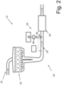
- FIG. 2 is a schematic illustration of an internal combustion engine system 12, according to an example.
- the internal combustion engine system 12 comprises an internal combustion engine 14 and an exhaust system 16.
- the internal combustion engine 14 may be a diesel engine. Irrespective of the type of engine, the internal combustion engine 14 may be adapted to feed exhaust gas to the exhaust system 16.
- the exhaust system 16 may comprise an exhaust conduit 18 and a nitric oxide reduction agent injection arrangement 20.
- the internal combustion engine system 12 may comprise an inlet system 22 adapted to feed inlet gas, such as air, to the internal combustion engine 14.
- the exhaust system 16 may comprise a selective catalytic reduction unit 24 which is adapted to receive exhaust gases from the exhaust conduit 18.
- the selective catalytic reduction unit 24 may be located downstream of the nitric oxide reduction agent injection arrangement 20 as seen in a direction of flow of the exhaust gas, which direction of flow is indicated by arrows in FIG. 2 .
- the selective catalytic reduction unit 24 may comprise a metal or an alloy layer (not shown) comprising one or more of the following: platinum and palladium.
- FIG. 3 is a schematic illustration of a nitric oxide reduction agent injection arrangement 20, according to an example.
- the nitric oxide reduction agent injection arrangement 20 is adapted to inject a nitric oxide reduction agent, such as urea, into an exhaust conduit 10 forming part of an exhaust system 16 (see FIG. 2 ) for an internal combustion engine system 12 (see FIG. 2 ).
- the nitric oxide reduction agent injection arrangement 20 comprises a nozzle 26 that is adapted to inject the nitric oxide reduction agent into the interior of the exhaust conduit 18 via a nozzle opening 28 of the nozzle 26.
- the nozzle 26 comprises a nozzle opening control portion 30 made of a shape memory material whereby a size and/or a shape of the nozzle opening 28 is dependent on at least a temperature of the nozzle opening control portion 30.
- the nozzle opening control portion 30 is a component separate from the portion of the nozzle 26 accommodating the nozzle opening 28.
- other examples of the nozzle opening control portion 30 will be presented hereinbelow.
- the shape memory material may comprise an alloy comprising any one of the following metals: Nickel and Titanium; Nickel, Titanium and Iron; Nickel, Titanium and Niobium; Nickel, Titanium and Copper; Iron, Manganese and Silicon; Copper, Zinc and Aluminium, and Copper, Aluminium and Nickel.
- the nitric oxide reduction agent injection 20 may comprise a heating element 32 at least thermally connected to the nozzle opening control portion 30.
- the heating element 32 may comprise an electric heating filament 34 connected to the nozzle opening control portion 30.
- the nitric oxide reduction agent injection arrangement 20 may comprise a source of energy 34, such as electric or thermal energy, which in turn is connected to the heating element 32, e.g. the electric heating filament 34, by means of one or more energy conducting elements 36.
- the source of energy 34 may be a source of electric energy, such as a battery, and each one of the one or more energy conducting elements 36 may be referred to as an electrical harness.
- the heating element 32 e.g., by controlling the source of energy 34 in the FIG. 3 example, the temperature of the nozzle opening control portion 30 may be controlled which in turn controls the size and/or the shape of the nozzle opening 28.
- the nitric oxide reduction agent injection arrangement 20 may comprise a source 38 of the nitric oxide reduction agent and a dosing unit 40 for controlling a flow of the nitric oxide reduction agent from the source 38 of the nitric oxide reduction agent to the nozzle opening 28.
- the dosing unit 40 may comprise an actuator (not shown).
- the dosing unit 40 may comprise an actuator (not shown).
- each nozzle 26 may be associated with an individual dosing unit 40 and an individual supply rail 39 such that the nitric oxide reduction agent may be fed to from the source 38 of nitric oxide reduction agent to a nozzle by means of a nozzle dedicated dosing unit 40 and a nozzle dedicated supply rail 39.
- FIG. 4A is a schematic illustration of a nitric oxide reduction agent injection arrangement 20, according to an example.
- the nozzle opening control portion 30 forms an integral part of the nozzle 26.
- the nozzle opening control portion 30 may be controlled so as to constrict at least a portion of the nozzle opening 28 (see FIG. 4B ) and/or to expand at least a portion of the nozzle opening 28 (see FIG. 4C ).
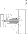
- FIG. 5 is a schematic illustration of a nitric oxide reduction agent injection arrangement 20, according to an example.
- the nozzle 26 is made of the shape memory material.
- the nozzle opening control portion 30 is the nozzle 26.
- FIG. 6 is a schematic illustration of a nitric oxide reduction agent injection arrangement 20, according to an example.
- the nitric oxide reduction agent injection arrangement 20 further comprises a sensor 42 for sensing exhaust gas information, indicative of at least one of the following: a temperature, a mixing pressure and a flow speed, of an exhaust gas in the exhaust conduit 18 upstream of the nozzle.
- the nitric oxide reduction agent injection arrangement 20 may further comprise a control unit 44 adapted to receive the exhaust gas information and to control a heating of the heating element 34 in response to the exhaust gas information.
- control unit 44 may also be adapted to issue control information to the dosing unit 40 of the nitric oxide reduction agent injection arrangement 20.
- FIG. 7 is a schematic illustration of a nitric oxide reduction agent injection arrangement 20, according to an example.
- the nitric oxide reduction agent injection arrangement 20 may comprise a plurality of nozzles 26, 26', 26", for instance a plurality of nozzles 26, 26', 26" in accordance with any one of the examples presented hereinabove.
- the nozzles of the plurality of nozzles 26, 26', 26" may be adapted to be evenly distributed around a circumference of the exhaust conduit.
- the exhaust conduit 18 may have a cross section with a cross sectional centre C and each nozzle of the plurality of nozzles 26, 26', 26" may be adapted to inject the nitric oxide reduction agent towards the cross sectional centre.
- the nitric oxide reduction agent may be fed from a source 38 of the nitric oxide reduction agent to each one of the nozzles 26, 26', 26" by means of a single dosing unit 40, that for instance may comprise an actuator, and a nitric oxide reduction agent supply rail 46 that is common to all the nozzles.
- each nozzle 26, 26', 26" may be associated with an individual dosing unit (not shown), that for instance may comprise an actuator, and an individual supply rail (not shown) such that the nitric oxide reduction agent may be fed to from the source of nitric oxide reduction agent to a nozzle by means of a nozzle dedicated dosing unit and a nozzle dedicated supply rail.
- an individual dosing unit not shown
- an individual supply rail not shown
- FIG. 8 is a flow chart of a method for controlling injection of a nitric oxide reduction agent, such as urea, into an exhaust conduit 18 forming part of an exhaust system 16 for an internal combustion engine system 12, using a nitric oxide reduction agent injection arrangement 20.
- the nitric oxide reduction agent injection arrangement 20 comprises a nozzle 26 that is adapted to inject the nitric oxide reduction agent into the interior of the exhaust conduit 18 via a nozzle opening 28 of the nozzle 26.
- the nozzle 26 comprises a nozzle opening control portion 30 made of a shape memory material whereby a size and/or a shape of the nozzle opening 28 is dependent on at least a temperature of the nozzle opening control portion 30.
- the nitric oxide reduction agent injection arrangement 20 comprises a heating element 34 at least thermally connected to the nozzle opening control portion 30.
- the method comprises: S10 sensing exhaust gas information, indicative of at least one of the following: a temperature, a mixing pressure and a flow speed, of an exhaust gas in the exhaust conduit 18 upstream of the nozzle 26, and S12 controlling a heating of the heating element 34 in response to the exhaust gas information.
- Example 1 A nitric oxide reduction agent injection arrangement 20 for injecting a nitric oxide reduction agent, such as urea, into an exhaust conduit 18 forming part of an exhaust system 16 for an internal combustion engine system 12, the nitric oxide reduction agent injection arrangement 20 comprising a nozzle 26 that is adapted to inject the nitric oxide reduction agent into the interior of the exhaust conduit 18 via a nozzle opening 28 of the nozzle 26, the nozzle 26 comprising a nozzle opening control portion 30 made of a shape memory material whereby a size and/or a shape of the nozzle opening 28 is dependent on at least a temperature of the nozzle opening control portion 30.
- a nitric oxide reduction agent such as urea
- Example 2 The nitric oxide reduction agent injection arrangement 20 of Example 1, wherein the nozzle opening control portion 30 forms an integral part of the nozzle 26.
- Example 3 The nitric oxide reduction agent injection arrangement 20 of Example 2, wherein the nozzle 26 is made of the shape memory material.
- Example 4 The nitric oxide reduction agent injection arrangement 20 of any one of the preceding Examples, further comprising a heating element 34 at least thermally connected to the nozzle opening control portion 30.
- Example 5 The nitric oxide reduction agent injection arrangement 20 of Example 4, wherein the heating element 34 comprises an electric heating filament 36 connected to the nozzle opening control portion 30.
- Example 6 The nitric oxide reduction agent injection arrangement 20 of Example 4 or Example 5, further comprising a sensor 42 for sensing exhaust gas information, indicative of at least one of the following: a temperature, a mixing pressure and a flow speed, of an exhaust gas in the exhaust conduit 18 upstream of the nozzle 26, the nitric oxide reduction agent injection arrangement 20 further comprising a control unit 44 adapted to receive the exhaust gas information and to control a heating of the heating element 34 in response to the exhaust gas information.
- a sensor 42 for sensing exhaust gas information, indicative of at least one of the following: a temperature, a mixing pressure and a flow speed, of an exhaust gas in the exhaust conduit 18 upstream of the nozzle 26, the nitric oxide reduction agent injection arrangement 20 further comprising a control unit 44 adapted to receive the exhaust gas information and to control a heating of the heating element 34 in response to the exhaust gas information.
- Example 7 The nitric oxide reduction agent injection arrangement 20 of any one of the preceding Examples, further comprising a source 38 of the nitric oxide reduction agent and a dosing unit 40 for controlling a flow of the nitric oxide reduction agent from the source 38 of the nitric oxide reduction agent to the nozzle opening 28.
- Example 8 The nitric oxide reduction agent injection arrangement 20 of any one of the preceding Examples, wherein the shape memory material comprises an alloy comprising any one of the following metals: Nickel and Titanium; Nickel, Titanium and Iron; Nickel, Titanium and Niobium; Nickel, Titanium and Copper; Iron, Manganese and Silicon; Copper, Zinc and Aluminium, and Copper, Aluminium and Nickel.
- Example 9 The nitric oxide reduction agent injection arrangement 20 of any one of the preceding Examples, wherein the nitric oxide reduction agent injection arrangement 20 comprises a plurality of nozzles 26, 26', 26" in accordance with any one of the preceding Examples.
- Example 10 The nitric oxide reduction agent injection arrangement 20 of Example 9, wherein the nozzles of the plurality of nozzles 26, 26', 26" are adapted to be evenly distributed around a circumference of the exhaust conduit 18.
- Example 11 The nitric oxide reduction agent injection arrangement 20 of Example 9 or Example 10, wherein the exhaust conduit 18 has a cross section with a cross sectional centre C and wherein each nozzle 26 of the plurality of nozzles 26, 26', 26" is adapted to inject the nitric oxide reduction agent towards the cross sectional centre C.
- Example 12 An exhaust system 16 for an internal combustion engine, the exhaust system 16 comprising an exhaust conduit 18 and a nitric oxide reduction agent injection arrangement 20 of any one of the preceding Examples.
- Example 13 The exhaust system 16 of Example 12, further comprising a selective catalytic reduction unit 24 being adapted to receive exhaust gases from the exhaust conduit 18, the selective catalytic reduction unit 24 being located downstream of the nitric oxide reduction agent injection arrangement 20 as seen in a direction of flow of the exhaust gas.
- Example 14 An internal combustion engine system 12 comprising an internal combustion engine 14 and a nitric oxide reduction agent injection arrangement 20 of any one of Examples 1 - 11 or an exhaust system 16 of any one of Examples 12 - 13.
- Example 15 A vehicle 10 comprising a nitric oxide reduction agent injection arrangement 20 of any one of Examples 1 - 11 or an exhaust system 16 of any one of Examples 12 - 13 or an internal combustion engine system 12 of Example 14.
- Example 16 A method for controlling injection of a nitric oxide reduction agent, such as urea, into an exhaust conduit 18 forming part of an exhaust system 16 for an internal combustion engine system 12, using a nitric oxide reduction agent injection arrangement 20, wherein the nitric oxide reduction agent injection arrangement 20 comprises a nozzle 26 that is adapted to inject the nitric oxide reduction agent into the interior of the exhaust conduit 18 via a nozzle opening 28 of the nozzle 26, the nozzle 26 comprising a nozzle opening control portion 30 made of a shape memory material whereby a size and/or a shape of the nozzle opening 28 is dependent on at least a temperature of the nozzle opening control portion 30, wherein the nitric oxide reduction agent injection arrangement 20 comprises a heating element 34 at least thermally connected to the nozzle opening control portion 30, wherein the method comprises sensing exhaust gas information, indicative of at least one of the following: a temperature, a mixing pressure and a flow speed, of an exhaust gas in the exhaust conduit 18 upstream of the nozzle 26, and controlling a heating of the heating
- Relative terms such as “below” or “above” or “upper” or “lower” or “horizontal” or “vertical” may be used herein to describe a relationship of one element to another element as illustrated in the Figures. It will be understood that these terms and those discussed above are intended to encompass different orientations of the device in addition to the orientation depicted in the Figures. It will be understood that when an element is referred to as being “connected” or “coupled” to another element, it can be directly connected or coupled to the other element, or intervening elements may be present. In contrast, when an element is referred to as being “directly connected” or “directly coupled” to another element, there are no intervening elements present.
Landscapes
- Engineering & Computer Science (AREA)
- Chemical & Material Sciences (AREA)
- Chemical Kinetics & Catalysis (AREA)
- Combustion & Propulsion (AREA)
- Mechanical Engineering (AREA)
- General Engineering & Computer Science (AREA)
- Health & Medical Sciences (AREA)
- Toxicology (AREA)
- Exhaust Gas After Treatment (AREA)
Abstract
The present disclosure relates to a nitrogen oxides reduction agent injection arrangement (20) for injecting a nitrogen oxides reduction agent, such as urea, into an exhaust conduit (18) forming part of an exhaust system (16) for an internal combustion engine system (12). The nitric oxide reduction agent injection arrangement (20) comprises a nozzle (26) that is adapted to inject the nitric oxide reduction agent into the interior of the exhaust conduit (18) via a nozzle opening (28) of the nozzle (26). The nozzle (26) comprises a nozzle opening control portion (30) made of a shape memory material whereby a size and/or a shape of the nozzle opening (28) is dependent on at least a temperature of the nozzle opening control portion (30). The shape memory material may be controlled by an electric heating element (34).
Description
- The disclosure relates generally to a system for injecting a nitric oxide reduction agent, such as urea, into an exhaust conduit forming part of an exhaust system for an internal combustion engine system. In particular aspects, the disclosure relates to a nitric oxide reduction agent injection arrangement. The disclosure can be applied to heavy-duty vehicles, such as trucks, buses, and construction equipment, among other vehicle types. Although the disclosure may be described with respect to a truck, the disclosure is not restricted to any particular vehicle.
- An internal combustion engine, in particular a diesel engine, may produce nitric oxide such as NO and/or NO2. It is generally desired to reduce the amount of nitric oxide emitted to the environment ambient of the internal combustion engine. To this end, an internal combustion engine system may comprise a selective catalytic reduction unit adapted to receive exhaust gases from the internal combustion engine. The exhaust gases reaching the selective catalytic reduction unit may also contain a nitric oxide reduction agent, such as urea. The exhaust gas emitted from the selective catalytic reduction unit may have a nitric oxide content being lower than the nitric oxide content of the exhaust gas entering the selective catalytic reduction unit. It may be desired to control the characteristics of the nitric oxide reduction agent that is fed to the selective catalytic reduction unit, e.g., in order to ensure that the nitric oxide reduction agent is appropriately mixed with the exhaust gas.
- According to a first aspect of the disclosure, there is provided a nitric oxide reduction agent injection arrangement for injecting a nitric oxide reduction agent, such as urea, into an exhaust conduit forming part of an exhaust system for an internal combustion engine system. The nitric oxide reduction agent injection arrangement comprises a nozzle that is adapted to inject the nitric oxide reduction agent into the interior of the exhaust conduit via a nozzle opening of the nozzle. The nozzle comprises a nozzle opening control portion made of a shape memory material whereby a size and/or a shape of the nozzle opening is dependent on at least a temperature of the nozzle opening control portion. The first aspect of the disclosure may seek to facilitate that the nitric oxide reduction agent is injected into the exhaust conduit in an appropriate manner. A technical benefit may include that the size and/or the shape of the nozzle opening is controllable which in turn implies that characteristics of the nitric oxide reduction agent, such as the flow and/or pressure, may be controlled in a straightforward manner. This in turn may imply that an appropriate mix of the exhaust gas and the nitric oxide reduction agent may be arrived at. As a non-limiting example, the shape memory material may be configured such that a size and/or a shape of said nozzle opening is dependent on at least a temperature of the nozzle opening control portion.
- Optionally in some examples, including in at least one preferred example, the nozzle opening control portion forms an integral part of the nozzle. A technical benefit may include that the size and/or the shape of the nozzle opening may be controlled with an appropriately low number of separate components.
- Optionally in some examples, including in at least one preferred example, the nozzle is made of the shape memory material. A technical benefit may include that the size and/or the shape of the nozzle opening may be controlled with an appropriately low number of separate components.
- Optionally in some examples, including in at least one preferred example, the nitric oxide reduction agent injection arrangement further comprises a heating element at least thermally connected to the nozzle opening control portion. A technical benefit may include that the temperature of the nozzle opening control portion, and consequently the size and/or the shape of the nozzle opening, may be controlled in a straightforward manner.
- Optionally in some examples, including in at least one preferred example, the heating element comprises an electric heating filament connected to the nozzle opening control portion. A technical benefit may include that the electric heating filament is a cost efficient component for controlling the temperature of the nozzle opening control portion.
- Optionally in some examples, including in at least one preferred example, the nitric oxide reduction agent injection arrangement further comprises a sensor for sensing exhaust gas information, indicative of at least one of the following: a temperature, a mixing pressure and a flow speed, of an exhaust gas in the exhaust conduit upstream of the nozzle. The nitric oxide reduction agent injection arrangement further comprises a control unit adapted to receive the exhaust gas information and to control a heating of the heating element in response to the exhaust gas information. A technical benefit may include that the heating of the heating element, and consequently the size and/or the shape of the nozzle opening, may be controlled in response to the exhaust gas information.
- Optionally in some examples, including in at least one preferred example, the nitric oxide reduction agent injection arrangement further comprises a source of the nitric oxide reduction agent and a dosing unit for controlling a flow of the nitric oxide reduction agent from the source of the nitric oxide reduction agent to the nozzle opening. A technical benefit may include that the supply and dosing of the nitric oxide reduction agent is enabled. Purely by way of example, the nitric oxide reduction agent may be fed from the source of the nitric oxide reduction agent to each one of the nozzles by means of a single dosing unit, that for instance may comprise an actuator, and a nitric oxide reduction agent supply rail that is common to all the nozzles. As another non-limiting example, each nozzle may be associated with an individual dosing unit, that for instance may comprise an actuator, and an individual supply rail such that the nitric oxide reduction agent may be fed to from the source of nitric oxide reduction agent to a nozzle by means of a nozzle dedicated dosing unit and a nozzle dedicated supply rail.
- Optionally in some examples, including in at least one preferred example, the shape memory material comprises an alloy comprising any one of the following metals: Nickel and Titanium; Nickel, Titanium and Iron; Nickel, Titanium and Niobium; Nickel, Titanium and Copper; Iron, Manganese and Silicon; Copper, Zinc and Aluminium, and Copper, Aluminium and Nickel. A technical benefit may include that an appropriate shape memory material is obtained.
- Optionally in some examples, including in at least one preferred example, the nitric oxide reduction agent injection arrangement comprises a plurality of nozzles in accordance with any one of the examples disclosed herein. A technical benefit may include that the arrangement may be able to provide a sufficiently high level of supply of nitric oxide reduction agent.
- Optionally in some examples, including in at least one preferred example, the nozzles of the plurality of nozzles are adapted to be evenly distributed around a circumference of the exhaust conduit. A technical benefit may include an appropriate mix of the nitric oxide reduction agent and the exhaust gas in the exhaust conduit.
- Optionally in some examples, including in at least one preferred example, the exhaust conduit has a cross section with a cross sectional centre and wherein each nozzle of the plurality of nozzles is adapted to inject the nitric oxide reduction agent towards the cross sectional centre. A technical benefit may include an appropriate mix of the nitric oxide reduction agent in the exhaust conduit.
- According to a second aspect of the disclosure, there is provided an exhaust system for an internal combustion engine. The exhaust system comprises an exhaust conduit and a nitric oxide reduction agent injection arrangement of the first aspect of the present disclosure. The second aspect of the disclosure may seek to obtain an appropriate mix of exhaust gas and nitric oxide reduction agent. A technical benefit may include that the size and/or the shape of the nozzle opening is controllable which in turn implies that characteristics of the nitric oxide reduction agent, such as the flow and/or pressure, may be controlled in a straightforward manner.
- Optionally in some examples, including in at least one preferred example, the exhaust system further comprises a selective catalytic reduction unit being adapted to receive exhaust gases from the exhaust conduit, the selective catalytic reduction unit being located downstream of the nitric oxide reduction agent injection arrangement as seen in a direction of flow of the exhaust gas. A technical benefit may include that the selective catalytic reduction unit and the nitric oxide reduction agent injection arrangement together may reduce the amount of nitric oxide leaving the selective catalytic reduction unit.
- According to a third aspect of the disclosure, there is provided an internal combustion engine system comprising an internal combustion engine and a nitric oxide reduction agent injection arrangement of the first aspect of the present disclosure or an exhaust system of the second aspect of the present disclosure. The third aspect of the disclosure may seek to enable that the amount of nitric oxide emitted from an internal combustion engine system is appropriately low. A technical benefit may include that the injection of the nitric oxide reduction agent is controlled in an appropriate manner which in turn implies that the amount of emitted nitric oxide may be appropriately low.
- According to a fourth aspect of the disclosure, there is provided a vehicle comprising a nitric oxide reduction agent injection arrangement of the first aspect of the present disclosure or an exhaust system of the second aspect of the present disclosure or an internal combustion engine system of the third aspect of the present disclosure. The fourth aspect of the disclosure may seek to enable that the amount of nitric oxide emitted from a vehicle is appropriately low. A technical benefit may include that the injection of the nitric oxide reduction agent is controlled in an appropriate manner which in turn implies that the amount of emitted nitric oxide may be appropriately low.
- According to a fifth aspect of the disclosure, there is provided a method for controlling injection of a nitric oxide reduction agent, such as urea, into an exhaust conduit forming part of an exhaust system for an internal combustion engine system, using a nitric oxide reduction agent injection arrangement. The nitric oxide reduction agent injection arrangement comprises a nozzle that is adapted to inject the nitric oxide reduction agent into the interior of the exhaust conduit via a nozzle opening of the nozzle. The nozzle comprises a nozzle opening control portion made of a shape memory material whereby a size and/or a shape of the nozzle opening is dependent on at least a temperature of the nozzle opening control portion. The nitric oxide reduction agent injection arrangement comprises a heating element at least thermally connected to the nozzle opening control portion. The method comprises sensing exhaust gas information, indicative of at least one of the following: a temperature, a mixing pressure and a flow speed, of an exhaust gas in the exhaust conduit upstream of the nozzle and controlling a heating of the heating element in response to the exhaust gas information. A technical benefit may include that the injection of the nitric oxide reduction agent is controlled in an appropriate manner which in turn implies that the amount of emitted nitric oxide may be appropriately low.
- The disclosed aspects, examples (including any preferred examples), and/or accompanying claims may be suitably combined with each other as would be apparent to anyone of ordinary skill in the art. Additional features and advantages are disclosed in the following description, claims, and drawings, and in part will be readily apparent therefrom to those skilled in the art or recognized by practicing the disclosure as described herein.
- Examples are described in more detail below with reference to the appended drawings.
-
FIG. 1 is a side view of a vehicle, in the form of a truck, according to an example. -
FIG. 2 is a schematic illustration of an internal combustion engine system, according to an example. -
FIG. 3 is a schematic illustration of a nitric oxide reduction agent injection arrangement, according to an example. -
FIG. 4A - FIG. 4C are schematic illustrations of a nitric oxide reduction agent injection arrangement, according to an example. -
FIG. 5 is a schematic illustration of a nitric oxide reduction agent injection arrangement, according to an example. -
FIG. 6 is a schematic illustration of a nitric oxide reduction agent injection arrangement, according to an example. -
FIG. 7 is a schematic illustration of a nitric oxide reduction agent injection arrangement, according to an example. -
FIG. 8 is a flowchart of a method, according to an example. - The detailed description set forth below provides information and examples of the disclosed technology with sufficient detail to enable those skilled in the art to practice the disclosure.
-
FIG. 1 is a side view of avehicle 10, in the form of a truck, according to an example. Thevehicle 10 may comprise an internalcombustion engine system 12 which is schematically indicated inFIG. 1 . -
FIG. 2 is a schematic illustration of an internalcombustion engine system 12, according to an example. As indicated inFIG. 2 , the internalcombustion engine system 12 comprises aninternal combustion engine 14 and anexhaust system 16. As a non-limiting example, theinternal combustion engine 14 may be a diesel engine. Irrespective of the type of engine, theinternal combustion engine 14 may be adapted to feed exhaust gas to theexhaust system 16. Moreover, theexhaust system 16 may comprise anexhaust conduit 18 and a nitric oxide reductionagent injection arrangement 20. Additionally, as a non-limiting example, the internalcombustion engine system 12 may comprise aninlet system 22 adapted to feed inlet gas, such as air, to theinternal combustion engine 14. - Furthermore, as a non-limiting example, the
exhaust system 16 may comprise a selectivecatalytic reduction unit 24 which is adapted to receive exhaust gases from theexhaust conduit 18. As indicated inFIG. 2 , the selectivecatalytic reduction unit 24 may be located downstream of the nitric oxide reductionagent injection arrangement 20 as seen in a direction of flow of the exhaust gas, which direction of flow is indicated by arrows inFIG. 2 . Purely by way of example, the selectivecatalytic reduction unit 24 may comprise a metal or an alloy layer (not shown) comprising one or more of the following: platinum and palladium. -
FIG. 3 is a schematic illustration of a nitric oxide reductionagent injection arrangement 20, according to an example. The nitric oxide reductionagent injection arrangement 20 is adapted to inject a nitric oxide reduction agent, such as urea, into anexhaust conduit 10 forming part of an exhaust system 16 (seeFIG. 2 ) for an internal combustion engine system 12 (seeFIG. 2 ). The nitric oxide reductionagent injection arrangement 20 comprises anozzle 26 that is adapted to inject the nitric oxide reduction agent into the interior of theexhaust conduit 18 via anozzle opening 28 of thenozzle 26. Thenozzle 26 comprises a nozzleopening control portion 30 made of a shape memory material whereby a size and/or a shape of thenozzle opening 28 is dependent on at least a temperature of the nozzleopening control portion 30. In theFIG. 3 example, the nozzleopening control portion 30 is a component separate from the portion of thenozzle 26 accommodating thenozzle opening 28. However, other examples of the nozzleopening control portion 30 will be presented hereinbelow. - However, for every example of the nozzle
opening control portion 30, the shape memory material may comprise an alloy comprising any one of the following metals: Nickel and Titanium; Nickel, Titanium and Iron; Nickel, Titanium and Niobium; Nickel, Titanium and Copper; Iron, Manganese and Silicon; Copper, Zinc and Aluminium, and Copper, Aluminium and Nickel. - Irrespective of the implementation of the nozzle
opening control portion 30, as indicated theFIG. 3 example, the nitric oxidereduction agent injection 20 may comprise aheating element 32 at least thermally connected to the nozzleopening control portion 30. Purely by way of example, theheating element 32 may comprise anelectric heating filament 34 connected to the nozzleopening control portion 30. Moreover, though purely by way of example, the nitric oxide reductionagent injection arrangement 20 may comprise a source ofenergy 34, such as electric or thermal energy, which in turn is connected to theheating element 32, e.g. theelectric heating filament 34, by means of one or moreenergy conducting elements 36. As a non-limiting example, the source ofenergy 34 may be a source of electric energy, such as a battery, and each one of the one or moreenergy conducting elements 36 may be referred to as an electrical harness. As such, by controlling theheating element 32, e.g., by controlling the source ofenergy 34 in theFIG. 3 example, the temperature of the nozzleopening control portion 30 may be controlled which in turn controls the size and/or the shape of thenozzle opening 28. - Furthermore, as a non-limiting example, as indicated in each one of the
FIG. 2 andFIG. 3 examples, the nitric oxide reductionagent injection arrangement 20 may comprise asource 38 of the nitric oxide reduction agent and adosing unit 40 for controlling a flow of the nitric oxide reduction agent from thesource 38 of the nitric oxide reduction agent to thenozzle opening 28. Purely by way of example, thedosing unit 40 may comprise an actuator (not shown). Purely by way of example, as indicated inFIG. 3 , eachnozzle 26 may be associated with anindividual dosing unit 40 and anindividual supply rail 39 such that the nitric oxide reduction agent may be fed to from thesource 38 of nitric oxide reduction agent to a nozzle by means of a nozzlededicated dosing unit 40 and a nozzlededicated supply rail 39. -
FIG. 4A is a schematic illustration of a nitric oxide reductionagent injection arrangement 20, according to an example. As compared to theFIG. 3 example, in theFIG. 4A example, the nozzleopening control portion 30 forms an integral part of thenozzle 26. Moreover, as indicated inFIG. 4B andFIG. 4C , the nozzleopening control portion 30 may be controlled so as to constrict at least a portion of the nozzle opening 28 (seeFIG. 4B ) and/or to expand at least a portion of the nozzle opening 28 (seeFIG. 4C ). -
FIG. 5 is a schematic illustration of a nitric oxide reductionagent injection arrangement 20, according to an example. As compared to theFIG. 3 andFIG. 4A - 4C examples, in theFIG. 5 example, thenozzle 26 is made of the shape memory material. As such, in theFIG. 5 example, the nozzleopening control portion 30 is thenozzle 26. -
FIG. 6 is a schematic illustration of a nitric oxide reductionagent injection arrangement 20, according to an example. In theFIG. 6 example, the nitric oxide reductionagent injection arrangement 20 further comprises asensor 42 for sensing exhaust gas information, indicative of at least one of the following: a temperature, a mixing pressure and a flow speed, of an exhaust gas in theexhaust conduit 18 upstream of the nozzle. Moreover, as indicated inFIG. 6 , the nitric oxide reductionagent injection arrangement 20 may further comprise acontrol unit 44 adapted to receive the exhaust gas information and to control a heating of theheating element 34 in response to the exhaust gas information. - Moreover, though purely by way of example, the
control unit 44 may also be adapted to issue control information to thedosing unit 40 of the nitric oxide reductionagent injection arrangement 20. -
FIG. 7 is a schematic illustration of a nitric oxide reductionagent injection arrangement 20, according to an example. As indicated inFIG. 7 , the nitric oxide reductionagent injection arrangement 20 may comprise a plurality ofnozzles nozzles FIG. 7 by way of example only, the nozzles of the plurality ofnozzles exhaust conduit 18 may have a cross section with a cross sectional centre C and each nozzle of the plurality ofnozzles FIG. 7 , the nitric oxide reduction agent may be fed from asource 38 of the nitric oxide reduction agent to each one of thenozzles single dosing unit 40, that for instance may comprise an actuator, and a nitric oxide reductionagent supply rail 46 that is common to all the nozzles. As another non-limiting example, eachnozzle -
FIG. 8 is a flow chart of a method for controlling injection of a nitric oxide reduction agent, such as urea, into anexhaust conduit 18 forming part of anexhaust system 16 for an internalcombustion engine system 12, using a nitric oxide reductionagent injection arrangement 20. As has been indicated above, the nitric oxide reductionagent injection arrangement 20 comprises anozzle 26 that is adapted to inject the nitric oxide reduction agent into the interior of theexhaust conduit 18 via anozzle opening 28 of thenozzle 26. Thenozzle 26 comprises a nozzleopening control portion 30 made of a shape memory material whereby a size and/or a shape of thenozzle opening 28 is dependent on at least a temperature of the nozzleopening control portion 30. The nitric oxide reductionagent injection arrangement 20 comprises aheating element 34 at least thermally connected to the nozzleopening control portion 30. The method comprises: S10 sensing exhaust gas information, indicative of at least one of the following: a temperature, a mixing pressure and a flow speed, of an exhaust gas in theexhaust conduit 18 upstream of thenozzle 26, and S12 controlling a heating of theheating element 34 in response to the exhaust gas information. - It should be noted that the present disclosure may be presented in accordance with any one of the below Examples.
- Example 1: A nitric oxide reduction
agent injection arrangement 20 for injecting a nitric oxide reduction agent, such as urea, into anexhaust conduit 18 forming part of anexhaust system 16 for an internalcombustion engine system 12, the nitric oxide reductionagent injection arrangement 20 comprising anozzle 26 that is adapted to inject the nitric oxide reduction agent into the interior of theexhaust conduit 18 via anozzle opening 28 of thenozzle 26, thenozzle 26 comprising a nozzleopening control portion 30 made of a shape memory material whereby a size and/or a shape of thenozzle opening 28 is dependent on at least a temperature of the nozzleopening control portion 30. - Example 2: The nitric oxide reduction
agent injection arrangement 20 of Example 1, wherein the nozzleopening control portion 30 forms an integral part of thenozzle 26. - Example 3: The nitric oxide reduction
agent injection arrangement 20 of Example 2, wherein thenozzle 26 is made of the shape memory material. - Example 4: The nitric oxide reduction
agent injection arrangement 20 of any one of the preceding Examples, further comprising aheating element 34 at least thermally connected to the nozzleopening control portion 30. - Example 5: The nitric oxide reduction
agent injection arrangement 20 of Example 4, wherein theheating element 34 comprises anelectric heating filament 36 connected to the nozzleopening control portion 30. - Example 6: The nitric oxide reduction
agent injection arrangement 20 of Example 4 or Example 5, further comprising asensor 42 for sensing exhaust gas information, indicative of at least one of the following: a temperature, a mixing pressure and a flow speed, of an exhaust gas in theexhaust conduit 18 upstream of thenozzle 26, the nitric oxide reductionagent injection arrangement 20 further comprising acontrol unit 44 adapted to receive the exhaust gas information and to control a heating of theheating element 34 in response to the exhaust gas information. - Example 7: The nitric oxide reduction
agent injection arrangement 20 of any one of the preceding Examples, further comprising asource 38 of the nitric oxide reduction agent and adosing unit 40 for controlling a flow of the nitric oxide reduction agent from thesource 38 of the nitric oxide reduction agent to thenozzle opening 28. - Example 8: The nitric oxide reduction
agent injection arrangement 20 of any one of the preceding Examples, wherein the shape memory material comprises an alloy comprising any one of the following metals: Nickel and Titanium; Nickel, Titanium and Iron; Nickel, Titanium and Niobium; Nickel, Titanium and Copper; Iron, Manganese and Silicon; Copper, Zinc and Aluminium, and Copper, Aluminium and Nickel. - Example 9: The nitric oxide reduction
agent injection arrangement 20 of any one of the preceding Examples, wherein the nitric oxide reductionagent injection arrangement 20 comprises a plurality ofnozzles - Example 10: The nitric oxide reduction
agent injection arrangement 20 of Example 9, wherein the nozzles of the plurality ofnozzles exhaust conduit 18. - Example 11: The nitric oxide reduction
agent injection arrangement 20 of Example 9 or Example 10, wherein theexhaust conduit 18 has a cross section with a cross sectional centre C and wherein eachnozzle 26 of the plurality ofnozzles - Example 12: An
exhaust system 16 for an internal combustion engine, theexhaust system 16 comprising anexhaust conduit 18 and a nitric oxide reductionagent injection arrangement 20 of any one of the preceding Examples. - Example 13: The
exhaust system 16 of Example 12, further comprising a selectivecatalytic reduction unit 24 being adapted to receive exhaust gases from theexhaust conduit 18, the selectivecatalytic reduction unit 24 being located downstream of the nitric oxide reductionagent injection arrangement 20 as seen in a direction of flow of the exhaust gas. - Example 14: An internal
combustion engine system 12 comprising aninternal combustion engine 14 and a nitric oxide reductionagent injection arrangement 20 of any one of Examples 1 - 11 or anexhaust system 16 of any one of Examples 12 - 13. - Example 15: A
vehicle 10 comprising a nitric oxide reductionagent injection arrangement 20 of any one of Examples 1 - 11 or anexhaust system 16 of any one of Examples 12 - 13 or an internalcombustion engine system 12 of Example 14. - Example 16: A method for controlling injection of a nitric oxide reduction agent, such as urea, into an
exhaust conduit 18 forming part of anexhaust system 16 for an internalcombustion engine system 12, using a nitric oxide reductionagent injection arrangement 20, wherein the nitric oxide reductionagent injection arrangement 20 comprises anozzle 26 that is adapted to inject the nitric oxide reduction agent into the interior of theexhaust conduit 18 via anozzle opening 28 of thenozzle 26, thenozzle 26 comprising a nozzleopening control portion 30 made of a shape memory material whereby a size and/or a shape of thenozzle opening 28 is dependent on at least a temperature of the nozzleopening control portion 30, wherein the nitric oxide reductionagent injection arrangement 20 comprises aheating element 34 at least thermally connected to the nozzleopening control portion 30, wherein the method comprises sensing exhaust gas information, indicative of at least one of the following: a temperature, a mixing pressure and a flow speed, of an exhaust gas in theexhaust conduit 18 upstream of thenozzle 26, and controlling a heating of theheating element 34 in response to the exhaust gas information. It should be noted that the method may be carried out with any example of the nitric oxide reductionagent injection arrangement 20 as presented above or in the below appended claims. - The terminology used herein is for the purpose of describing particular aspects only and is not intended to be limiting of the disclosure. As used herein, the singular forms "a," "an," and "the" are intended to include the plural forms as well, unless the context clearly indicates otherwise. As used herein, the term "and/or" includes any and all combinations of one or more of the associated listed items. It will be further understood that the terms "comprises," "comprising," "includes," and/or "including" when used herein specify the presence of stated features, integers, actions, steps, operations, elements, and/or components, but do not preclude the presence or addition of one or more other features, integers, actions, steps, operations, elements, components, and/or groups thereof.
- It will be understood that, although the terms first, second, etc., may be used herein to describe various elements, these elements should not be limited by these terms. These terms are only used to distinguish one element from another. For example, a first element could be termed a second element, and, similarly, a second element could be termed a first element without departing from the scope of the present disclosure.
- Relative terms such as "below" or "above" or "upper" or "lower" or "horizontal" or "vertical" may be used herein to describe a relationship of one element to another element as illustrated in the Figures. It will be understood that these terms and those discussed above are intended to encompass different orientations of the device in addition to the orientation depicted in the Figures. It will be understood that when an element is referred to as being "connected" or "coupled" to another element, it can be directly connected or coupled to the other element, or intervening elements may be present. In contrast, when an element is referred to as being "directly connected" or "directly coupled" to another element, there are no intervening elements present.
- Unless otherwise defined, all terms (including technical and scientific terms) used herein have the same meaning as commonly understood by one of ordinary skill in the art to which this disclosure belongs. It will be further understood that terms used herein should be interpreted as having a meaning consistent with their meaning in the context of this specification and the relevant art and will not be interpreted in an idealized or overly formal sense unless expressly so defined herein.
- It is to be understood that the present disclosure is not limited to the aspects described above and illustrated in the drawings; rather, the skilled person will recognize that many changes and modifications may be made within the scope of the present disclosure and appended claims. In the drawings and specification, there have been disclosed aspects for purposes of illustration only and not for purposes of limitation, the scope of the disclosure being set forth in the following claims.
Claims (15)
- A nitric oxide reduction agent injection arrangement (20) for injecting a nitric oxide reduction agent, such as urea, into an exhaust conduit (18) forming part of an exhaust system (16) for an internal combustion engine system (12), said nitric oxide reduction agent injection arrangement (20) comprising a nozzle (26) that is adapted to inject said nitric oxide reduction agent into the interior of said exhaust conduit (18) via a nozzle opening (28) of said nozzle (26), said nozzle (26) comprising a nozzle opening control portion (30) made of a shape memory material whereby a size and/or a shape of said nozzle opening (28) is dependent on at least a temperature of said nozzle opening control portion (30).
- The nitric oxide reduction agent injection arrangement (20) of claim 1, wherein said nozzle opening control portion (30) forms an integral part of said nozzle (26).
- The nitric oxide reduction agent injection arrangement (20) of claim 2, wherein said nozzle (26) is made of said shape memory material.
- The nitric oxide reduction agent injection arrangement (20) of any one of the preceding claims, further comprising a heating element (34) at least thermally connected to said nozzle opening control portion (30).
- The nitric oxide reduction agent injection arrangement (20) of claim 4, wherein said heating element (34) comprises an electric heating filament (36) connected to said nozzle opening control portion (30).
- The nitric oxide reduction agent injection arrangement (20) of claim 4 or claim 5, further comprising a sensor (42) for sensing exhaust gas information, indicative of at least one of the following: a temperature, a mixing pressure and a flow speed, of an exhaust gas in said exhaust conduit (18) upstream of said nozzle (26), said nitric oxide reduction agent injection arrangement (20) further comprising a control unit (44) adapted to receive said exhaust gas information and to control a heating of said heating element (34) in response to said exhaust gas information.
- The nitric oxide reduction agent injection arrangement (20) of any one of the preceding claims, further comprising a source (38) of said nitric oxide reduction agent and a dosing unit (40) for controlling a flow of said nitric oxide reduction agent from said source (38) of said nitric oxide reduction agent to said nozzle opening (28).
- The nitric oxide reduction agent injection arrangement (20) of any one of the preceding claims, wherein said shape memory material comprises an alloy comprising any one of the following metals: Nickel and Titanium; Nickel, Titanium and Iron; Nickel, Titanium and Niobium; Nickel, Titanium and Copper; Iron, Manganese and Silicon; Copper, Zinc and Aluminium, and Copper, Aluminium and Nickel.
- The nitric oxide reduction agent injection arrangement (20) of any one of the preceding claims, wherein said nitric oxide reduction agent injection arrangement (20) comprises a plurality of nozzles (26, 26', 26") in accordance with any one of the preceding claims.
- The nitric oxide reduction agent injection arrangement (20) of claim 9, wherein said nozzles of said plurality of nozzles (26, 26', 26") are adapted to be evenly distributed around a circumference of said exhaust conduit (18).
- The nitric oxide reduction agent injection arrangement (20) of claim 9 or claim 10, wherein said exhaust conduit (18) has a cross section with a cross sectional centre (C) and wherein each nozzle (26) of said plurality of nozzles (26, 26', 26") is adapted to inject said nitric oxide reduction agent towards said cross sectional centre (C).
- An exhaust system (16) for an internal combustion engine, said exhaust system (16) comprising an exhaust conduit (18) and a nitric oxide reduction agent injection arrangement (20) of any one of the preceding claims.
- The exhaust system (16) of claim 12, further comprising a selective catalytic reduction unit (24) being adapted to receive exhaust gases from said exhaust conduit (18), said selective catalytic reduction unit (24) being located downstream of said nitric oxide reduction agent injection arrangement (20) as seen in a direction of flow of said exhaust gas.
- An internal combustion engine system (12) comprising an internal combustion engine (14) and a nitric oxide reduction agent injection arrangement (20) of any one of claims 1-11 or an exhaust system (16) of any one of claims 12 - 13.
- A vehicle (10) comprising a nitric oxide reduction agent injection arrangement (20) of any one of claims 1 - 11 or an exhaust system (16) of any one of claims 12 - 13 or an internal combustion engine system (12) of claim 14.
Priority Applications (3)
| Application Number | Priority Date | Filing Date | Title |
|---|---|---|---|
| EP23174224.8A EP4464878A1 (en) | 2023-05-19 | 2023-05-19 | A nox reduction agent injection arrangement |
| US18/661,844 US20240384674A1 (en) | 2023-05-19 | 2024-05-13 | Nitrogen oxides reduction agent injection arrangement |
| EP24176482.8A EP4464879A1 (en) | 2023-05-19 | 2024-05-17 | A nitrogen oxides reduction agent injection arrangement |
Applications Claiming Priority (1)
| Application Number | Priority Date | Filing Date | Title |
|---|---|---|---|
| EP23174224.8A EP4464878A1 (en) | 2023-05-19 | 2023-05-19 | A nox reduction agent injection arrangement |
Publications (1)
| Publication Number | Publication Date |
|---|---|
| EP4464878A1 true EP4464878A1 (en) | 2024-11-20 |
Family
ID=86469234
Family Applications (2)
| Application Number | Title | Priority Date | Filing Date |
|---|---|---|---|
| EP23174224.8A Withdrawn EP4464878A1 (en) | 2023-05-19 | 2023-05-19 | A nox reduction agent injection arrangement |
| EP24176482.8A Pending EP4464879A1 (en) | 2023-05-19 | 2024-05-17 | A nitrogen oxides reduction agent injection arrangement |
Family Applications After (1)
| Application Number | Title | Priority Date | Filing Date |
|---|---|---|---|
| EP24176482.8A Pending EP4464879A1 (en) | 2023-05-19 | 2024-05-17 | A nitrogen oxides reduction agent injection arrangement |
Country Status (2)
| Country | Link |
|---|---|
| US (1) | US20240384674A1 (en) |
| EP (2) | EP4464878A1 (en) |
Citations (4)
| Publication number | Priority date | Publication date | Assignee | Title |
|---|---|---|---|---|
| JPS60247046A (en) * | 1984-05-21 | 1985-12-06 | Hitachi Ltd | Fuel atomization controller |
| JPH1047049A (en) * | 1996-08-01 | 1998-02-17 | Toyota Motor Corp | Exhaust gas purification device for internal combustion engine |
| US20060248881A1 (en) * | 2004-01-22 | 2006-11-09 | Haruyuki Yokota | System for Injecting Fuel into Diesel Engine Exhaust Pipe |
| EP3587791A1 (en) * | 2018-06-21 | 2020-01-01 | Claverham Limited | Flow control nozzle |
-
2023
- 2023-05-19 EP EP23174224.8A patent/EP4464878A1/en not_active Withdrawn
-
2024
- 2024-05-13 US US18/661,844 patent/US20240384674A1/en active Pending
- 2024-05-17 EP EP24176482.8A patent/EP4464879A1/en active Pending
Patent Citations (4)
| Publication number | Priority date | Publication date | Assignee | Title |
|---|---|---|---|---|
| JPS60247046A (en) * | 1984-05-21 | 1985-12-06 | Hitachi Ltd | Fuel atomization controller |
| JPH1047049A (en) * | 1996-08-01 | 1998-02-17 | Toyota Motor Corp | Exhaust gas purification device for internal combustion engine |
| US20060248881A1 (en) * | 2004-01-22 | 2006-11-09 | Haruyuki Yokota | System for Injecting Fuel into Diesel Engine Exhaust Pipe |
| EP3587791A1 (en) * | 2018-06-21 | 2020-01-01 | Claverham Limited | Flow control nozzle |
Also Published As
| Publication number | Publication date |
|---|---|
| EP4464879A1 (en) | 2024-11-20 |
| US20240384674A1 (en) | 2024-11-21 |
Similar Documents
| Publication | Publication Date | Title |
|---|---|---|
| EP3660287B1 (en) | Exhaust gas aftertreatment system and method for treating the waste gas of a combustion engine | |
| EP1244512B1 (en) | Device and method for subsequently treating exhaust gases | |
| US8156734B2 (en) | Method for operating a reagent metering valve and apparatus for carrying out the method | |
| EP3775513B1 (en) | Method for controlling urea mixers to reduce nox emission from combustion engines | |
| EP3111066B1 (en) | Method and system for controlling nitrogen oxide emissions from a combustion engine | |
| EP2907984B1 (en) | Internal combustion engine | |
| US20100122523A1 (en) | Cold-start engine loading for accelerated warming of exhaust aftertreatment system | |
| CN110454259A (en) | It is the method for multiple electric heaters power supply with single power supply | |
| EP2606210B1 (en) | Method for operating an exhaust gas treatment device | |
| EP3418518A1 (en) | Waste gas treatment system and method for treating the waste gas of a combustion engine | |
| DE102017222235A1 (en) | Method and device for heating an exhaust gas purification system of an internal combustion engine | |
| DE102016215207A1 (en) | Exhaust aftertreatment system with exhaust gas recirculation and two ammonia oxidation catalysts | |
| EP3486444A1 (en) | Exhaust gas treatment method for a combustion engine | |
| DE102020100529B4 (en) | Internal combustion engine and methods for heating the exhaust system of such an internal combustion engine | |
| US20040083722A1 (en) | Diesel aftertreatment systems | |
| EP4026994B1 (en) | Waste gas treatment system and method for treating the waste gas of a combustion engine | |
| EP2921667A1 (en) | Exhaust gas purification device for internal-combustion engine | |
| EP3341597B1 (en) | Method and system for treatment of an exhaust gas stream | |
| US7926467B2 (en) | Droplet generator for engine system | |
| EP4464878A1 (en) | A nox reduction agent injection arrangement | |
| EP2087214B1 (en) | Engine with exhaust cooling and method | |
| US10107165B2 (en) | Method and apparatus for controlling reductant injection into an exhaust gas feedstream of an internal combustion engine | |
| US10883404B2 (en) | Method and apparatus for controlling reductant injection into an exhaust gas feedstream of an internal combustion engine | |
| US20160281563A1 (en) | Exhaust system for an internal combustion engine of a motor vehicle and method for operating an exhaust system | |
| US20120285144A1 (en) | Exhaust after treatment system and method for treating exhaust |
Legal Events
| Date | Code | Title | Description |
|---|---|---|---|
| PUAI | Public reference made under article 153(3) epc to a published international application that has entered the european phase |
Free format text: ORIGINAL CODE: 0009012 |
|
| STAA | Information on the status of an ep patent application or granted ep patent |
Free format text: STATUS: THE APPLICATION HAS BEEN PUBLISHED |
|
| AK | Designated contracting states |
Kind code of ref document: A1 Designated state(s): AL AT BE BG CH CY CZ DE DK EE ES FI FR GB GR HR HU IE IS IT LI LT LU LV MC ME MK MT NL NO PL PT RO RS SE SI SK SM TR |
|
| STAA | Information on the status of an ep patent application or granted ep patent |
Free format text: STATUS: THE APPLICATION IS DEEMED TO BE WITHDRAWN |
|
| 18D | Application deemed to be withdrawn |
Effective date: 20250521 |