EP4464872A1 - Method for extracting rotor dynamic orbit from blade tip clearance and time of arrival measurements - Google Patents
Method for extracting rotor dynamic orbit from blade tip clearance and time of arrival measurements Download PDFInfo
- Publication number
- EP4464872A1 EP4464872A1 EP24175797.0A EP24175797A EP4464872A1 EP 4464872 A1 EP4464872 A1 EP 4464872A1 EP 24175797 A EP24175797 A EP 24175797A EP 4464872 A1 EP4464872 A1 EP 4464872A1
- Authority
- EP
- European Patent Office
- Prior art keywords
- engine
- rotor
- orbit
- sensor
- blade tip
- Prior art date
- Legal status (The legal status is an assumption and is not a legal conclusion. Google has not performed a legal analysis and makes no representation as to the accuracy of the status listed.)
- Pending
Links
Images



Classifications
-
- F—MECHANICAL ENGINEERING; LIGHTING; HEATING; WEAPONS; BLASTING
- F01—MACHINES OR ENGINES IN GENERAL; ENGINE PLANTS IN GENERAL; STEAM ENGINES
- F01D—NON-POSITIVE DISPLACEMENT MACHINES OR ENGINES, e.g. STEAM TURBINES
- F01D17/00—Regulating or controlling by varying flow
- F01D17/02—Arrangement of sensing elements
-
- G—PHYSICS
- G01—MEASURING; TESTING
- G01M—TESTING STATIC OR DYNAMIC BALANCE OF MACHINES OR STRUCTURES; TESTING OF STRUCTURES OR APPARATUS, NOT OTHERWISE PROVIDED FOR
- G01M15/00—Testing of engines
- G01M15/14—Testing gas-turbine engines or jet-propulsion engines
-
- F—MECHANICAL ENGINEERING; LIGHTING; HEATING; WEAPONS; BLASTING
- F01—MACHINES OR ENGINES IN GENERAL; ENGINE PLANTS IN GENERAL; STEAM ENGINES
- F01D—NON-POSITIVE DISPLACEMENT MACHINES OR ENGINES, e.g. STEAM TURBINES
- F01D21/00—Shutting-down of machines or engines, e.g. in emergency; Regulating, controlling, or safety means not otherwise provided for
- F01D21/003—Arrangements for testing or measuring
-
- G—PHYSICS
- G01—MEASURING; TESTING
- G01B—MEASURING LENGTH, THICKNESS OR SIMILAR LINEAR DIMENSIONS; MEASURING ANGLES; MEASURING AREAS; MEASURING IRREGULARITIES OF SURFACES OR CONTOURS
- G01B21/00—Measuring arrangements or details thereof, where the measuring technique is not covered by the other groups of this subclass, unspecified or not relevant
- G01B21/16—Measuring arrangements or details thereof, where the measuring technique is not covered by the other groups of this subclass, unspecified or not relevant for measuring distance of clearance between spaced objects
-
- F—MECHANICAL ENGINEERING; LIGHTING; HEATING; WEAPONS; BLASTING
- F01—MACHINES OR ENGINES IN GENERAL; ENGINE PLANTS IN GENERAL; STEAM ENGINES
- F01D—NON-POSITIVE DISPLACEMENT MACHINES OR ENGINES, e.g. STEAM TURBINES
- F01D11/00—Preventing or minimising internal leakage of working-fluid, e.g. between stages
- F01D11/08—Preventing or minimising internal leakage of working-fluid, e.g. between stages for sealing space between rotor blade tips and stator
- F01D11/14—Adjusting or regulating tip-clearance, i.e. distance between rotor-blade tips and stator casing
-
- F—MECHANICAL ENGINEERING; LIGHTING; HEATING; WEAPONS; BLASTING
- F05—INDEXING SCHEMES RELATING TO ENGINES OR PUMPS IN VARIOUS SUBCLASSES OF CLASSES F01-F04
- F05D—INDEXING SCHEME FOR ASPECTS RELATING TO NON-POSITIVE-DISPLACEMENT MACHINES OR ENGINES, GAS-TURBINES OR JET-PROPULSION PLANTS
- F05D2270/00—Control
- F05D2270/80—Devices generating input signals, e.g. transducers, sensors, cameras or strain gauges
- F05D2270/821—Displacement measuring means, e.g. inductive
Definitions
- the present disclosure is directed to a system and method of determining rotor-dynamic orbits from blade tip clearance and time of arrival measurements.
- a system for determining rotor-dynamic orbit information comprising an engine case supporting at least one engine stage, each at least one engine stage including a rotor having blades; at least one blade tip sensor operatively coupled to the engine case and in operative communication with the blades; at least one compensation sensor in operative communication with the at least one blade tip sensor; and an orbit controller in operative communication with the at least one blade tip sensor and the at least one compensation sensor.
- Particular embodiments may further include at least one of the following optional features, alone or in combination with each other.
- a further embodiment of any of the foregoing embodiments may additionally and/or alternatively include the at least one blade tip sensor is configured to sense the location of the blades relative to the engine case.
- a further embodiment of any of the foregoing embodiments may additionally and/or alternatively include the at least one compensation sensor is configured to sense the location of the at least one blade tip sensor relative to the engine case and configured to indicate the relative motion of the at least one blade tip sensor.
- a further embodiment of any of the foregoing embodiments may additionally and/or alternatively include the orbit controller is configured to utilize measurements of tip clearance and tip timing data to extract a dynamic orbit for a single stage of the engine.
- a further embodiment of any of the foregoing embodiments may additionally and/or alternatively include the orbit controller is configured to align each of the dynamic orbits determined for each measured at least one stage of the engine.
- a further embodiment of any of the foregoing embodiments may additionally and/or alternatively include the orbit controller is configured to provide an estimate of a full rotor dynamic shape of a combination of each of the at least one stage of the engine.
- a further embodiment of any of the foregoing embodiments may additionally and/or alternatively include the system for determining the rotor-dynamic orbit information further comprising a blade monitoring system in operative communication with the orbit controller.
- a system for determining rotor-dynamic orbit information comprising a gas turbine engine having at least one engine stage; an engine case supporting the at least one engine stage, each at least one engine stage including a rotor having a plurality of blades; at least one blade tip sensor operatively coupled to the engine case surrounding the plurality of blades within the at least one engine stage, the at least one blade tip sensor in operative communication with the plurality of blades; at least one compensation sensor in operative communication with the at least one blade tip sensor; and an orbit controller in operative communication with the at least one blade tip sensor and the at least one compensation sensor.
- Particular embodiments may further include at least one of the following optional features, alone or in combination with each other.
- a further embodiment of any of the foregoing embodiments may additionally and/or alternatively include the system for determining the rotor-dynamic orbit information further comprising a blade monitoring system in operative communication with the orbit controller.
- a further embodiment of any of the foregoing embodiments may additionally and/or alternatively include the at least one blade tip sensor is configured to sense the location of the blades relative to the engine case.
- a further embodiment of any of the foregoing embodiments may additionally and/or alternatively include the at least one compensation sensor is configured to sense the location of the at least one blade tip sensor relative to the engine case and configured to indicate the relative motion of the at least one blade tip sensor.
- a further embodiment of any of the foregoing embodiments may additionally and/or alternatively include the orbit controller is configured to utilize measurements of tip clearance and tip timing data to extract a dynamic orbit for a single stage of the engine.
- a further embodiment of any of the foregoing embodiments may additionally and/or alternatively include the orbit controller is configured to align each of the dynamic orbits determined for each measured at least one engine stage; wherein the orbit controller is configured to provide an estimate of a full rotor dynamic shape of a combination of each of the at least one engine stage.
- a process for determining rotor-dynamic orbit information comprising providing an engine case supporting at least one engine stage, each at least one engine stage including a rotor having blades; operatively coupling at least one blade tip sensor to the engine case; the at least one blade tip sensor in operative communication with the blades; coupling at least one compensation sensor in operative communication with the at least one blade tip sensor; and placing an orbit controller in operative communication with the at least one blade tip sensor and the at least one compensation sensor.
- Particular embodiments may further include at least one of the following optional features, alone or in combination with each other.
- a further embodiment of any of the foregoing embodiments may additionally and/or alternatively include the process further comprising determining an absolute reference frame for the at least one blade tip sensor.
- a further embodiment of any of the foregoing embodiments may additionally and/or alternatively include the process further comprising synthesizing a single stage rotor orbit.
- a further embodiment of any of the foregoing embodiments may additionally and/or alternatively include the process further comprising determining the at least one engine stage rotor orbit.
- a further embodiment of any of the foregoing embodiments may additionally and/or alternatively include the process further comprising configuring the orbit controller to align each rotor orbit determined for each measured at least one engine stage.
- a further embodiment of any of the foregoing embodiments may additionally and/or alternatively include the process further comprising aligning each of the at least one engine stage rotor orbit across an engine.
- a further embodiment of any of the foregoing embodiments may additionally and/or alternatively include the process further comprising configuring the orbit controller to provide an estimate of a full rotor dynamic shape of a combination of each of the at least one engine stage.
- FIG. 1 schematically illustrates a gas turbine engine 20.
- the gas turbine engine 20 is disclosed herein as a two-spool turbofan that generally incorporates a fan section 22, a compressor section 24, a combustor section 26 and a turbine section 28.
- the fan section 22 may include a single-stage fan 42 having a plurality of fan blades 43.
- the fan blades 43 may have a fixed stagger angle or may have a variable pitch to direct incoming airflow from an engine inlet.
- the fan 42 drives air along a bypass flow path B in a bypass duct 13 defined within a housing 15 such as a fan case or nacelle, and also drives air along a core flow path C for compression and communication into the combustor section 26 then expansion through the turbine section 28.
- a splitter 29 aft of the fan 42 divides the air between the bypass flow path B and the core flow path C.
- the housing 15 may surround the fan 42 to establish an outer diameter of the bypass duct 13.
- the splitter 29 may establish an inner diameter of the bypass duct 13.
- the exemplary engine 20 generally includes a low speed spool 30 and a high speed spool 32 mounted for rotation about an engine central longitudinal axis A relative to an engine static structure 36 via several bearing systems 38. It should be understood that various bearing systems 38 at various locations may alternatively or additionally be provided, and the location of bearing systems 38 may be varied as appropriate to the application.
- the low speed spool 30 generally includes an inner shaft 40 that interconnects, a first (or low) pressure compressor 44 and a first (or low) pressure turbine 46.
- the inner shaft 40 is connected to the fan 42 through a speed change mechanism, which in the exemplary gas turbine engine 20 is illustrated as a geared architecture 48 to drive the fan 42 at a lower speed than the low speed spool 30.
- the inner shaft 40 may interconnect the low pressure compressor 44 and low pressure turbine 46 such that the low pressure compressor 44 and low pressure turbine 46 are rotatable at a common speed and in a common direction.
- the low pressure turbine 46 drives both the fan 42 and low pressure compressor 44 through the geared architecture 48 such that the fan 42 and low pressure compressor 44 are rotatable at a common speed.
- the high speed spool 32 includes an outer shaft 50 that interconnects a second (or high) pressure compressor 52 and a second (or high) pressure turbine 54.
- a combustor 56 is arranged in the exemplary gas turbine 20 between the high pressure compressor 52 and the high pressure turbine 54.
- a mid-turbine frame 57 of the engine static structure 36 may be arranged generally between the high pressure turbine 54 and the low pressure turbine 46.
- the mid-turbine frame 57 further supports bearing systems 38 in the turbine section 28.
- the inner shaft 40 and the outer shaft 50 are concentric and rotate via bearing systems 38 about the engine central longitudinal axis A which is collinear with their longitudinal axes.
- Airflow in the core flow path C is compressed by the low pressure compressor 44 then the high pressure compressor 52, mixed and burned with fuel in the combustor 56, then expanded through the high pressure turbine 54 and low pressure turbine 46.
- the mid-turbine frame 57 includes airfoils 59 which are in the core flow path C.
- the turbines 46, 54 rotationally drive the respective low speed spool 30 and high speed spool 32 in response to the expansion.
- gear system 48 may be located aft of the low pressure compressor, or aft of the combustor section 26 or even aft of turbine section 28, and fan 42 may be positioned forward or aft of the location of gear system 48.
- the low pressure compressor 44, high pressure compressor 52, high pressure turbine 54 and low pressure turbine 46 each include one or more stages having a row of rotatable airfoils. Each stage may include a row of static vanes adjacent the rotatable airfoils.
- the rotatable airfoils and vanes are schematically indicated at 47 and 49.
- the engine 20 may be a high-bypass geared aircraft engine.
- the bypass ratio can be greater than or equal to 10.0 and less than or equal to about 18.0, or more narrowly can be less than or equal to 16.0.
- the geared architecture 48 may be an epicyclic gear train, such as a planetary gear system or a star gear system.
- the epicyclic gear train may include a sun gear, a ring gear, a plurality of intermediate gears meshing with the sun gear and ring gear, and a carrier that supports the intermediate gears.
- the sun gear may provide an input to the gear train.
- the ring gear (e.g., star gear system) or carrier (e.g., planetary gear system) may provide an output of the gear train to drive the fan 42.
- a gear reduction ratio may be greater than or equal to 2.3, or more narrowly greater than or equal to 3.0, and in some embodiments the gear reduction ratio is greater than or equal to 3.4.
- the gear reduction ratio may be less than or equal to 4.0.
- the fan diameter is significantly larger than that of the low pressure compressor 44.
- the low pressure turbine 46 can have a pressure ratio that is greater than or equal to 8.0 and in some embodiments is greater than or equal to 10.0.
- the low pressure turbine pressure ratio can be less than or equal to 13.0, or more narrowly less than or equal to 12.0.
- Low pressure turbine 46 pressure ratio is pressure measured prior to an inlet of low pressure turbine 46 as related to the pressure at the outlet of the low pressure turbine 46 prior to an exhaust nozzle. It should be understood, however, that the above parameters are only exemplary of one embodiment of a geared architecture engine and that the present invention is applicable to other gas turbine engines including direct drive turbofans. All of these parameters are measured at the cruise condition described below.
- the fan section 22 of the engine 20 is designed for a particular flight condition -- typically cruise at about 0.8 Mach and about 35,000 feet (10,668 meters).
- the flight condition of 0.8 Mach and 35,000 ft (10,668 meters), with the engine at its best fuel consumption - also known as "bucket cruise Thrust Specific Fuel Consumption ('TSFC')" - is the industry standard parameter of pounds-mass per hour lbm/hr of fuel flow rate being burned divided by pounds-force lbf of thrust the engine produces at that minimum point.
- 'TSFC' Thrust Specific Fuel Consumption
- Low fan pressure ratio is the pressure ratio across the fan blade 43 alone, without a Fan Exit Guide Vane (“FEGV”) system. A distance is established in a radial direction between the inner and outer diameters of the bypass duct 13 at an axial position corresponding to a leading edge of the splitter 29 relative to the engine central longitudinal axis A.
- the low fan pressure ratio is a spanwise average of the pressure ratios measured across the fan blade 43 alone over radial positions corresponding to the distance.
- the low fan pressure ratio can be less than or equal to 1.45, or more narrowly greater than or equal to 1.25, such as between 1.30 and 1.40.
- Low corrected fan tip speed is the actual fan tip speed in ft/sec divided by an industry standard temperature correction of [(Tram °R) / (518.7 °R) ] 0.5 .
- the "low corrected fan tip speed” can be less than or equal to 1150.0 ft / second (350.5 meters/second), and greater than or equal to 1000.0 ft / second (304.8 meters/second).
- the example gas turbine engine 20 includes a blade monitoring system 60.
- the example blade monitoring system 60 includes at least one blade tip clearance sensor 62 that is mounted to the fan case 15 surrounding the plurality of fan blades 42 within the fan section 22.
- the blade monitoring system 60 receives signals each time one of the fan blades 42 passes in close proximity to the tip sensors 62.
- a tip 64 of the fan blade 42 passes proximate the tip sensors 62.
- the system 60 utilizes the signals for detecting and assessing vibratory modes occurring in each of the fan blades 42.
- the blade monitoring system 60 can also detect blade tip clearance.
- example system 60 is described by way of example with regard to fan blades 42 of the fan section 22, other airfoils such as those provided in the compressor and turbine sections 24, 28 are also within the contemplation of this disclosure.
- the tip sensor 62 can be disposed within the fan case 15 and mounted such that the sensor 62 detects a portion of the fan blade 42 at a location spaced at a distance D from the blade 42.
- a distance D is disclosed, other distance and relative angular orientation relative to the fan blade 42 may be utilized for the sensor within the contemplation of this disclosure.
- the example sensor 62 can be any known sensor and is located within the fan case 15 radially outboard of the fan blade 42. It should be understood that any sensor configuration for sensing the presence and path of a fan blade are also within the contemplation of this disclosure. Moreover, although two sensors are shown in FIG. 1 , the disclosed system and method may operate with one or more sensors 62 as shown in Fig. 2 , is within the contemplation of this disclosure.
- the sensor 62 registers the presence of the fan blade tip 64 as the tip 64 passes the sensor 62 during rotation about the axis A and generates a signal 66.
- a signal level 68 of the signal 66 is indicative of a distance between the tip 64 of the fan blade 42 and the sensor 62.
- the example signal 66 is an electrical signal such as a current or voltage produced by the sensor 62 and communicated to the system 60.
- passing of the tip 64 of the fan blade 42 past the sensor 62 generates a sine wave shaped signal 66 indicative of a path of the fan blade 42.
- the slope 70 of the signal 66 at a zero crossing point decreases.
- the timing of the fan blade 42 passing the sensor 62 can also be measured with the monitoring system 60.
- the monitoring system 60 can be coupled with the fan section 22, the compressor section 24 and the turbine section 28 to obtain data across multiple stages along the entire gas turbine engine 20.
- the rotors 72 of the low pressure compressor 44, low pressure turbine 46, high pressure compressor 52, high pressure turbine 54 and fan 42 can be monitored.
- Each of the sensors 62 can include a compensation sensor 74 in operative communication with the sensors 62.
- the compensation sensor 74 can be configured to indicate the relative motion of the sensors 62. During operation of the gas turbine engine 20, the sensors 62 can vibrate and be displaced. The rotors 72 can also be displaced and move relative to the case 15. The displacement of the sensors 62 and the rotors 72 can influence the measurements of the blade tip 64 clearance.
- the compensation sensor 74 can be utilized to provide data which can be employed to compensate for the relative motion of the sensor 62 and create an absolute measurement.
- the absolute measurement can create an absolute reference frame for the sensor 62.
- the relative motion of the sensor 62 can be subtracted from the relative distance from the blade tip to the sensor to place the distance in an absolute reference frame.
- Compensation can be accomplished by subtracting the time or frequency-domain signals of the compensation sensors from the sensors. Compensation can also be accomplished by the orbit controller in real-time so that the output is in an absolute reference frame. Additionally, the rotor 72 motion can also be provided with an absolute reference frame for the rotor 72.
- the compensation sensors can be configured to measure position, velocity, or acceleration.
- each sensor 62 output along with the compensation sensor 74 output is combined into an orbit controller 76.
- the orbit controller 76 can be integrated with the blade monitoring system 60 or be configured independent.
- the orbit controller 76 also receives input from the rotor 72.
- the orbit controller 76 synthesizes the outputs from the sensors 62, 74 and determines an absolute sensor reference frame 78.
- the orbit controller 76 also determines an absolute rotor reference frame 80.
- the orbit controller 76 can utilize the measurements of the tip clearance and tip timing data to extract a dynamic orbit 82 for a single rotor stage of the engine 20.
- the dynamic orbit 82 represents a particular orbital pattern for a given rotor stage in a given engine 20.
- the orbit controller 76 may include hardware, firmware, and/or software components that are configured to perform the functions disclosed herein, including the functions of the system and method for determining the rotor-dynamic orbit information by utilizing tip clearance and time of arrival measurements. While not specifically shown, the orbit controller 76 may include other computing devices (e.g., servers, mobile computing devices, etc.) and computer systems which may be in communication with each other and/or the orbit controller 76 via a communication network 84 to perform one or more of the disclosed functions. The orbit controller 76 may include at least one processor 86 (e.g., a controller, microprocessor, microcontroller, digital signal processor, etc.), memory 88, and an input/output (I/O) subsystem 90.
- processor 86 e.g., a controller, microprocessor, microcontroller, digital signal processor, etc.
- the orbit controller 76 may be embodied as any type of computing device e.g., a server, an enterprise computer system, a network of computers, a combination of computers and other electronic devices, or other electronic devices.
- the I/O subsystem 90 typically includes, for example, an I/O controller, a memory controller, and one or more I/O ports.
- the processor 86 and the I/O subsystem 90 are communicatively coupled to the memory 88.
- the memory 88 may be embodied as any type of computer memory device (e.g., volatile memory such as various forms of random access memory).
- the I/O subsystem 90 is communicatively coupled to a number of hardware, firmware, and/or software components, including a data storage device 92, a display 94, a communication subsystem 96, and a user interface (UI) subsystem 98.
- the data storage device 92 may include one or more hard drives or other suitable persistent storage devices (e.g., flash memory, memory cards, memory sticks, and/or others).
- each of the single stage rotor dynamic orbits 82 determined for each stage can be combined and aligned employing the orbit controller 76.
- the blade tip clearance data across multiple stages can be aligned to provide an estimate of a full rotor dynamic shape 100 of all of the stages combined.
- the alignment process can be accomplished by aligning time of arrival timestamps or using a common signature shared across multiple stages.
- the common signature can be a rotor speed.
- the alignment can be accomplished by using characteristic fluctuations of rotor speed time of arrival signatures of response on the rotor.
- the process allows for compensation of sensor 62 measurements by use of the compensation sensor 74 located on/near the tip sensor 62 configured to compensate the relative motion of the tip sensor 62 with the absolute sensor measurement.
- the various systems that are utilized to make the measurements of the blade tips and rotors do not have to be synchronized.
- the full dynamic rotor shape 100 can be used to validate models of the entire engine 20.
- the full dynamic rotor shape can be used for health and safety monitoring of the engine operation.
- the process 110 can include a step 112 where the tip sensor 62 and compensation sensor 74 can be installed.
- the tip sensors 62 can sense the rotary motion of the blade 42 and rotor 72.
- the absolute reference frame 78, 80 can be determined.
- the single stage orbit can be synthesized. Synthesis can be accomplished by the controller by fitting an orbital shape to the measurements of at least 2 probes at each passing of a blade. Fitting can be accomplished using sensor measurements in the time or frequency-domain.
- the single stage rotor orbit can be determined at step 120.
- Step 122 includes alignment of the orbits of each stage across the engine 20.
- Step 124 includes determining the full engine dynamic rotor shape.
- a technical advantage of the disclosed system and method for determining the rotor-dynamic orbit information can include generating new information from existing data captured using tip clearance probes.
- Another technical advantage of the disclosed system and method for determining the rotor-dynamic orbit information can include utilizing already in place tip clearance probes configured for recording turbomachinery tip clearance.
- Another technical advantage of the disclosed system and method for determining the rotor-dynamic orbit information can include no additional cost is required to measure the rotor-dynamic orbits.
- Another technical advantage of the disclosed system and method for determining the rotor-dynamic orbit information can include a unique estimate of the 3D dynamic response of a shaft by use of synthesis and alignment of orbits from multiple rotor stages.
Landscapes
- Engineering & Computer Science (AREA)
- Mechanical Engineering (AREA)
- General Engineering & Computer Science (AREA)
- Physics & Mathematics (AREA)
- General Physics & Mathematics (AREA)
- Chemical & Material Sciences (AREA)
- Combustion & Propulsion (AREA)
- Turbine Rotor Nozzle Sealing (AREA)
Abstract
Description
- The present disclosure is directed to a system and method of determining rotor-dynamic orbits from blade tip clearance and time of arrival measurements.
- Current measurements of rotor dynamic orbits in turbomachinery can be limited to proximity probes located 90 degrees apart and directed at a continuous rotor or shaft surface. Current methods of measuring rotor dynamic orbits can require special test instrumentation located deep in an engine to allow for sensors at the necessary locations. The instrumentation can limit the measurements to a single shaft axial location. The legacy method can require significant cost and time.
- What is needed is a system and method for determining the rotor-dynamic orbit information by utilizing blade tip clearance and time of arrival measurements.
- In accordance with the present disclosure, there is provided a system for determining rotor-dynamic orbit information comprising an engine case supporting at least one engine stage, each at least one engine stage including a rotor having blades; at least one blade tip sensor operatively coupled to the engine case and in operative communication with the blades; at least one compensation sensor in operative communication with the at least one blade tip sensor; and an orbit controller in operative communication with the at least one blade tip sensor and the at least one compensation sensor.
- Particular embodiments may further include at least one of the following optional features, alone or in combination with each other.
- A further embodiment of any of the foregoing embodiments may additionally and/or alternatively include the at least one blade tip sensor is configured to sense the location of the blades relative to the engine case.
- A further embodiment of any of the foregoing embodiments may additionally and/or alternatively include the at least one compensation sensor is configured to sense the location of the at least one blade tip sensor relative to the engine case and configured to indicate the relative motion of the at least one blade tip sensor.
- A further embodiment of any of the foregoing embodiments may additionally and/or alternatively include the orbit controller is configured to utilize measurements of tip clearance and tip timing data to extract a dynamic orbit for a single stage of the engine.
- A further embodiment of any of the foregoing embodiments may additionally and/or alternatively include the orbit controller is configured to align each of the dynamic orbits determined for each measured at least one stage of the engine.
- A further embodiment of any of the foregoing embodiments may additionally and/or alternatively include the orbit controller is configured to provide an estimate of a full rotor dynamic shape of a combination of each of the at least one stage of the engine.
- A further embodiment of any of the foregoing embodiments may additionally and/or alternatively include the system for determining the rotor-dynamic orbit information further comprising a blade monitoring system in operative communication with the orbit controller.
- In accordance with the present disclosure, there is provided a system for determining rotor-dynamic orbit information comprising a gas turbine engine having at least one engine stage; an engine case supporting the at least one engine stage, each at least one engine stage including a rotor having a plurality of blades; at least one blade tip sensor operatively coupled to the engine case surrounding the plurality of blades within the at least one engine stage, the at least one blade tip sensor in operative communication with the plurality of blades; at least one compensation sensor in operative communication with the at least one blade tip sensor; and an orbit controller in operative communication with the at least one blade tip sensor and the at least one compensation sensor.
- Particular embodiments may further include at least one of the following optional features, alone or in combination with each other.
- A further embodiment of any of the foregoing embodiments may additionally and/or alternatively include the system for determining the rotor-dynamic orbit information further comprising a blade monitoring system in operative communication with the orbit controller.
- A further embodiment of any of the foregoing embodiments may additionally and/or alternatively include the at least one blade tip sensor is configured to sense the location of the blades relative to the engine case.
- A further embodiment of any of the foregoing embodiments may additionally and/or alternatively include the at least one compensation sensor is configured to sense the location of the at least one blade tip sensor relative to the engine case and configured to indicate the relative motion of the at least one blade tip sensor.
- A further embodiment of any of the foregoing embodiments may additionally and/or alternatively include the orbit controller is configured to utilize measurements of tip clearance and tip timing data to extract a dynamic orbit for a single stage of the engine.
- A further embodiment of any of the foregoing embodiments may additionally and/or alternatively include the orbit controller is configured to align each of the dynamic orbits determined for each measured at least one engine stage; wherein the orbit controller is configured to provide an estimate of a full rotor dynamic shape of a combination of each of the at least one engine stage.
- In accordance with the present disclosure, there is provided a process for determining rotor-dynamic orbit information comprising providing an engine case supporting at least one engine stage, each at least one engine stage including a rotor having blades; operatively coupling at least one blade tip sensor to the engine case; the at least one blade tip sensor in operative communication with the blades; coupling at least one compensation sensor in operative communication with the at least one blade tip sensor; and placing an orbit controller in operative communication with the at least one blade tip sensor and the at least one compensation sensor.
- Particular embodiments may further include at least one of the following optional features, alone or in combination with each other.
- A further embodiment of any of the foregoing embodiments may additionally and/or alternatively include the process further comprising determining an absolute reference frame for the at least one blade tip sensor.
- A further embodiment of any of the foregoing embodiments may additionally and/or alternatively include the process further comprising synthesizing a single stage rotor orbit.
- A further embodiment of any of the foregoing embodiments may additionally and/or alternatively include the process further comprising determining the at least one engine stage rotor orbit.
- A further embodiment of any of the foregoing embodiments may additionally and/or alternatively include the process further comprising configuring the orbit controller to align each rotor orbit determined for each measured at least one engine stage.
- A further embodiment of any of the foregoing embodiments may additionally and/or alternatively include the process further comprising aligning each of the at least one engine stage rotor orbit across an engine.
- A further embodiment of any of the foregoing embodiments may additionally and/or alternatively include the process further comprising configuring the orbit controller to provide an estimate of a full rotor dynamic shape of a combination of each of the at least one engine stage.
- Other details of the system and method for determining the rotor-dynamic orbit information by utilizing blade tip clearance and time of arrival measurements are set forth in the following detailed description and the accompanying drawings wherein like reference numerals depict like elements.
-
Fig. 1 is a cross section view of an exemplary gas turbine engine. -
Fig. 2 is a schematic representation of an exemplary blade monitoring system and tip clearance probe configuration. -
Fig. 3 is a schematic representation of an exemplary process diagram for single stage rotor orbit. -
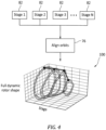
Fig. 4 is a schematic representation of an exemplary process diagram for full dynamic rotor orbit shape. -
Fig. 5 is a process diagram. -
Figure 1 schematically illustrates agas turbine engine 20. Thegas turbine engine 20 is disclosed herein as a two-spool turbofan that generally incorporates afan section 22, acompressor section 24, acombustor section 26 and aturbine section 28. Thefan section 22 may include a single-stage fan 42 having a plurality offan blades 43. Thefan blades 43 may have a fixed stagger angle or may have a variable pitch to direct incoming airflow from an engine inlet. Thefan 42 drives air along a bypass flow path B in abypass duct 13 defined within ahousing 15 such as a fan case or nacelle, and also drives air along a core flow path C for compression and communication into thecombustor section 26 then expansion through theturbine section 28. Asplitter 29 aft of thefan 42 divides the air between the bypass flow path B and the core flow path C. Thehousing 15 may surround thefan 42 to establish an outer diameter of thebypass duct 13. Thesplitter 29 may establish an inner diameter of thebypass duct 13. Although depicted as a two-spool turbofan gas turbine engine in the disclosed non-limiting embodiment, it should be understood that the concepts described herein are not limited to use with two-spool turbofans as the teachings may be applied to other types of turbine engines including three-spool architectures. - The
exemplary engine 20 generally includes alow speed spool 30 and ahigh speed spool 32 mounted for rotation about an engine central longitudinal axis A relative to an enginestatic structure 36 viaseveral bearing systems 38. It should be understood thatvarious bearing systems 38 at various locations may alternatively or additionally be provided, and the location ofbearing systems 38 may be varied as appropriate to the application. - The
low speed spool 30 generally includes aninner shaft 40 that interconnects, a first (or low)pressure compressor 44 and a first (or low)pressure turbine 46. Theinner shaft 40 is connected to thefan 42 through a speed change mechanism, which in the exemplarygas turbine engine 20 is illustrated as a gearedarchitecture 48 to drive thefan 42 at a lower speed than thelow speed spool 30. Theinner shaft 40 may interconnect thelow pressure compressor 44 andlow pressure turbine 46 such that thelow pressure compressor 44 andlow pressure turbine 46 are rotatable at a common speed and in a common direction. In other embodiments, thelow pressure turbine 46 drives both thefan 42 andlow pressure compressor 44 through the gearedarchitecture 48 such that thefan 42 andlow pressure compressor 44 are rotatable at a common speed. Although this application discloses gearedarchitecture 48, its teaching may benefit direct drive engines having no geared architecture. Thehigh speed spool 32 includes anouter shaft 50 that interconnects a second (or high)pressure compressor 52 and a second (or high)pressure turbine 54. Acombustor 56 is arranged in theexemplary gas turbine 20 between thehigh pressure compressor 52 and thehigh pressure turbine 54. Amid-turbine frame 57 of the enginestatic structure 36 may be arranged generally between thehigh pressure turbine 54 and thelow pressure turbine 46. Themid-turbine frame 57 further supports bearingsystems 38 in theturbine section 28. Theinner shaft 40 and theouter shaft 50 are concentric and rotate viabearing systems 38 about the engine central longitudinal axis A which is collinear with their longitudinal axes. - Airflow in the core flow path C is compressed by the
low pressure compressor 44 then thehigh pressure compressor 52, mixed and burned with fuel in thecombustor 56, then expanded through thehigh pressure turbine 54 andlow pressure turbine 46. Themid-turbine frame 57 includesairfoils 59 which are in the core flow path C. Theturbines low speed spool 30 andhigh speed spool 32 in response to the expansion. It will be appreciated that each of the positions of thefan section 22,compressor section 24,combustor section 26,turbine section 28, and fandrive gear system 48 may be varied. For example,gear system 48 may be located aft of the low pressure compressor, or aft of thecombustor section 26 or even aft ofturbine section 28, andfan 42 may be positioned forward or aft of the location ofgear system 48. - The
low pressure compressor 44,high pressure compressor 52,high pressure turbine 54 andlow pressure turbine 46 each include one or more stages having a row of rotatable airfoils. Each stage may include a row of static vanes adjacent the rotatable airfoils. The rotatable airfoils and vanes are schematically indicated at 47 and 49. - The
engine 20 may be a high-bypass geared aircraft engine. The bypass ratio can be greater than or equal to 10.0 and less than or equal to about 18.0, or more narrowly can be less than or equal to 16.0. The gearedarchitecture 48 may be an epicyclic gear train, such as a planetary gear system or a star gear system. The epicyclic gear train may include a sun gear, a ring gear, a plurality of intermediate gears meshing with the sun gear and ring gear, and a carrier that supports the intermediate gears. The sun gear may provide an input to the gear train. The ring gear (e.g., star gear system) or carrier (e.g., planetary gear system) may provide an output of the gear train to drive thefan 42. A gear reduction ratio may be greater than or equal to 2.3, or more narrowly greater than or equal to 3.0, and in some embodiments the gear reduction ratio is greater than or equal to 3.4. The gear reduction ratio may be less than or equal to 4.0. The fan diameter is significantly larger than that of thelow pressure compressor 44. Thelow pressure turbine 46 can have a pressure ratio that is greater than or equal to 8.0 and in some embodiments is greater than or equal to 10.0. The low pressure turbine pressure ratio can be less than or equal to 13.0, or more narrowly less than or equal to 12.0.Low pressure turbine 46 pressure ratio is pressure measured prior to an inlet oflow pressure turbine 46 as related to the pressure at the outlet of thelow pressure turbine 46 prior to an exhaust nozzle. It should be understood, however, that the above parameters are only exemplary of one embodiment of a geared architecture engine and that the present invention is applicable to other gas turbine engines including direct drive turbofans. All of these parameters are measured at the cruise condition described below. - A significant amount of thrust is provided by the bypass flow B due to the high bypass ratio. The
fan section 22 of theengine 20 is designed for a particular flight condition -- typically cruise at about 0.8 Mach and about 35,000 feet (10,668 meters). The flight condition of 0.8 Mach and 35,000 ft (10,668 meters), with the engine at its best fuel consumption - also known as "bucket cruise Thrust Specific Fuel Consumption ('TSFC')" - is the industry standard parameter of pounds-mass per hour lbm/hr of fuel flow rate being burned divided by pounds-force lbf of thrust the engine produces at that minimum point. The engine parameters described above, and those in the next paragraph are measured at this condition unless otherwise specified. - "Low fan pressure ratio" is the pressure ratio across the
fan blade 43 alone, without a Fan Exit Guide Vane ("FEGV") system. A distance is established in a radial direction between the inner and outer diameters of thebypass duct 13 at an axial position corresponding to a leading edge of thesplitter 29 relative to the engine central longitudinal axis A. The low fan pressure ratio is a spanwise average of the pressure ratios measured across thefan blade 43 alone over radial positions corresponding to the distance. The low fan pressure ratio can be less than or equal to 1.45, or more narrowly greater than or equal to 1.25, such as between 1.30 and 1.40. "Low corrected fan tip speed" is the actual fan tip speed in ft/sec divided by an industry standard temperature correction of [(Tram °R) / (518.7 °R) ]0.5. The "low corrected fan tip speed" can be less than or equal to 1150.0 ft / second (350.5 meters/second), and greater than or equal to 1000.0 ft / second (304.8 meters/second). - Referring also to
Fig. 2 , the examplegas turbine engine 20 includes ablade monitoring system 60. The exampleblade monitoring system 60 includes at least one bladetip clearance sensor 62 that is mounted to thefan case 15 surrounding the plurality offan blades 42 within thefan section 22. Theblade monitoring system 60 receives signals each time one of thefan blades 42 passes in close proximity to thetip sensors 62. In this example, atip 64 of thefan blade 42 passes proximate thetip sensors 62. Thesystem 60 utilizes the signals for detecting and assessing vibratory modes occurring in each of thefan blades 42. Theblade monitoring system 60 can also detect blade tip clearance. - As appreciated although the
example system 60 is described by way of example with regard tofan blades 42 of thefan section 22, other airfoils such as those provided in the compressor andturbine sections - The
tip sensor 62 can be disposed within thefan case 15 and mounted such that thesensor 62 detects a portion of thefan blade 42 at a location spaced at a distance D from theblade 42. Although an example distance D is disclosed, other distance and relative angular orientation relative to thefan blade 42 may be utilized for the sensor within the contemplation of this disclosure. - The
example sensor 62 can be any known sensor and is located within thefan case 15 radially outboard of thefan blade 42. It should be understood that any sensor configuration for sensing the presence and path of a fan blade are also within the contemplation of this disclosure. Moreover, although two sensors are shown inFIG. 1 , the disclosed system and method may operate with one ormore sensors 62 as shown inFig. 2 , is within the contemplation of this disclosure. - The
sensor 62 registers the presence of thefan blade tip 64 as thetip 64 passes thesensor 62 during rotation about the axis A and generates asignal 66. Asignal level 68 of thesignal 66 is indicative of a distance between thetip 64 of thefan blade 42 and thesensor 62. Theexample signal 66 is an electrical signal such as a current or voltage produced by thesensor 62 and communicated to thesystem 60. In this example, passing of thetip 64 of thefan blade 42 past thesensor 62 generates a sine wave shapedsignal 66 indicative of a path of thefan blade 42. As thetip 64 of thefan blade 42 becomes spaced a greater distance away from thesensor 62, theslope 70 of thesignal 66 at a zero crossing point decreases. The timing of thefan blade 42 passing thesensor 62 can also be measured with themonitoring system 60. - The
monitoring system 60 can be coupled with thefan section 22, thecompressor section 24 and theturbine section 28 to obtain data across multiple stages along the entiregas turbine engine 20. Therotors 72 of thelow pressure compressor 44,low pressure turbine 46,high pressure compressor 52,high pressure turbine 54 andfan 42 can be monitored. - Each of the
sensors 62 can include acompensation sensor 74 in operative communication with thesensors 62. Thecompensation sensor 74 can be configured to indicate the relative motion of thesensors 62. During operation of thegas turbine engine 20, thesensors 62 can vibrate and be displaced. Therotors 72 can also be displaced and move relative to thecase 15. The displacement of thesensors 62 and therotors 72 can influence the measurements of theblade tip 64 clearance. Thecompensation sensor 74 can be utilized to provide data which can be employed to compensate for the relative motion of thesensor 62 and create an absolute measurement. The absolute measurement can create an absolute reference frame for thesensor 62. The relative motion of thesensor 62 can be subtracted from the relative distance from the blade tip to the sensor to place the distance in an absolute reference frame. Compensation can be accomplished by subtracting the time or frequency-domain signals of the compensation sensors from the sensors. Compensation can also be accomplished by the orbit controller in real-time so that the output is in an absolute reference frame. Additionally, therotor 72 motion can also be provided with an absolute reference frame for therotor 72. The compensation sensors can be configured to measure position, velocity, or acceleration. - Referring also to
Fig. 3 , the diagram for single stage rotor orbit is shown. Eachsensor 62 output along with thecompensation sensor 74 output is combined into anorbit controller 76. Theorbit controller 76 can be integrated with theblade monitoring system 60 or be configured independent. Theorbit controller 76 also receives input from therotor 72. Theorbit controller 76 synthesizes the outputs from thesensors sensor reference frame 78. Theorbit controller 76 also determines an absoluterotor reference frame 80. Theorbit controller 76 can utilize the measurements of the tip clearance and tip timing data to extract adynamic orbit 82 for a single rotor stage of theengine 20. Thedynamic orbit 82 represents a particular orbital pattern for a given rotor stage in a givenengine 20. - The
orbit controller 76 may include hardware, firmware, and/or software components that are configured to perform the functions disclosed herein, including the functions of the system and method for determining the rotor-dynamic orbit information by utilizing tip clearance and time of arrival measurements. While not specifically shown, theorbit controller 76 may include other computing devices (e.g., servers, mobile computing devices, etc.) and computer systems which may be in communication with each other and/or theorbit controller 76 via acommunication network 84 to perform one or more of the disclosed functions. Theorbit controller 76 may include at least one processor 86 (e.g., a controller, microprocessor, microcontroller, digital signal processor, etc.),memory 88, and an input/output (I/O)subsystem 90. Theorbit controller 76 may be embodied as any type of computing device e.g., a server, an enterprise computer system, a network of computers, a combination of computers and other electronic devices, or other electronic devices. Although not specifically shown, the I/O subsystem 90 typically includes, for example, an I/O controller, a memory controller, and one or more I/O ports. Theprocessor 86 and the I/O subsystem 90 are communicatively coupled to thememory 88. Thememory 88 may be embodied as any type of computer memory device (e.g., volatile memory such as various forms of random access memory). - The I/
O subsystem 90 is communicatively coupled to a number of hardware, firmware, and/or software components, including adata storage device 92, adisplay 94, acommunication subsystem 96, and a user interface (UI)subsystem 98. Thedata storage device 92 may include one or more hard drives or other suitable persistent storage devices (e.g., flash memory, memory cards, memory sticks, and/or others). - Referring also to
Fig. 4 , each of the single stage rotordynamic orbits 82 determined for each stage can be combined and aligned employing theorbit controller 76. The blade tip clearance data across multiple stages can be aligned to provide an estimate of a full rotordynamic shape 100 of all of the stages combined. The alignment process can be accomplished by aligning time of arrival timestamps or using a common signature shared across multiple stages. The common signature can be a rotor speed. The alignment can be accomplished by using characteristic fluctuations of rotor speed time of arrival signatures of response on the rotor. The process allows for compensation ofsensor 62 measurements by use of thecompensation sensor 74 located on/near thetip sensor 62 configured to compensate the relative motion of thetip sensor 62 with the absolute sensor measurement. The various systems that are utilized to make the measurements of the blade tips and rotors do not have to be synchronized. The fulldynamic rotor shape 100 can be used to validate models of theentire engine 20. The full dynamic rotor shape can be used for health and safety monitoring of the engine operation. - Referring also to
Fig. 5 , a process map is shown. Theprocess 110 can include astep 112 where thetip sensor 62 andcompensation sensor 74 can be installed. Atstep 114 thetip sensors 62 can sense the rotary motion of theblade 42 androtor 72. At step 116, theabsolute reference frame step 118, the single stage orbit can be synthesized. Synthesis can be accomplished by the controller by fitting an orbital shape to the measurements of at least 2 probes at each passing of a blade. Fitting can be accomplished using sensor measurements in the time or frequency-domain. The single stage rotor orbit can be determined atstep 120. Step 122 includes alignment of the orbits of each stage across theengine 20. Step 124 includes determining the full engine dynamic rotor shape. - A technical advantage of the disclosed system and method for determining the rotor-dynamic orbit information can include generating new information from existing data captured using tip clearance probes.
- Another technical advantage of the disclosed system and method for determining the rotor-dynamic orbit information can include utilizing already in place tip clearance probes configured for recording turbomachinery tip clearance.
- Another technical advantage of the disclosed system and method for determining the rotor-dynamic orbit information can include no additional cost is required to measure the rotor-dynamic orbits.
- Another technical advantage of the disclosed system and method for determining the rotor-dynamic orbit information can include a unique estimate of the 3D dynamic response of a shaft by use of synthesis and alignment of orbits from multiple rotor stages.
- There has been provided a system and method for determining the rotor-dynamic orbit information. While the system and method for determining the rotor-dynamic orbit information has been described in the context of specific embodiments thereof, other unforeseen alternatives, modifications, and variations may become apparent to those skilled in the art having read the foregoing description. Accordingly, it is intended to embrace those alternatives, modifications, and variations which fall within the broad scope of the appended claims.
Claims (15)
- A system for determining rotor-dynamic orbit information comprising:an engine case supporting at least one engine stage, each at least one engine stage including a rotor having blades;at least one blade tip sensor operatively coupled to the engine case and in operative communication with the blades;at least one compensation sensor in operative communication with the at least one blade tip sensor; andan orbit controller in operative communication with the at least one blade tip sensor and the at least one compensation sensor.
- The system for determining the rotor-dynamic orbit information according to claim 1, wherein the at least one blade tip sensor is configured to sense the location of the blades relative to the engine case.
- The system for determining the rotor-dynamic orbit information according to claim 1 or 2, wherein the at least one compensation sensor is configured to sense the location of the at least one blade tip sensor relative to the engine case and configured to indicate the relative motion of the at least one blade tip sensor.
- The system for determining the rotor-dynamic orbit information according to any of claims 1 to 3, wherein the orbit controller is configured to utilize measurements of tip clearance and tip timing data to extract a dynamic orbit for a single stage of the engine.
- The system for determining the rotor-dynamic orbit information according to claim 4, wherein the orbit controller is configured to align each of the dynamic orbits determined for each measured at least one stage of the engine.
- The system for determining the rotor-dynamic orbit information according to claim 5, wherein the orbit controller is configured to provide an estimate of a full rotor dynamic shape of a combination of each of the at least one stage of the engine.
- The system for determining the rotor-dynamic orbit information according to any of claims 1 to 6, further comprising:
a blade monitoring system in operative communication with the orbit controller. - The system for determining rotor-dynamic orbit information according to any of claims 1 to 7, comprising a gas turbine engine having at least one engine stage;
wherein:the engine case supports the at least one engine stage, each at least one engine stage including a rotor having a plurality of blades;the at least one blade tip sensor is operatively coupled to the engine case surrounding the plurality of blades within the at least one engine stage, the at least one blade tip sensor is in operative communication with the plurality of blades;the at least one compensation sensor is in operative communication with the at least one blade tip sensor; andthe orbit controller is in operative communication with the at least one blade tip sensor and the at least one compensation sensor. - The system for determining the rotor-dynamic orbit information according to claim 8, further comprising:
a blade monitoring system in operative communication with the orbit controller. - A process for determining rotor-dynamic orbit information comprising:providing an engine case supporting at least one engine stage, each at least one engine stage including a rotor having blades;operatively coupling at least one blade tip sensor to the engine case; the at least one blade tip sensor in operative communication with the blades;coupling at least one compensation sensor in operative communication with the at least one blade tip sensor; andplacing an orbit controller in operative communication with the at least one blade tip sensor and the at least one compensation sensor.
- The process of claim 10, further comprising:
determining an absolute reference frame for the at least one blade tip sensor. - The process of claim 10 or 11, further comprising:
synthesizing a single stage rotor orbit. - The process of any of claims 1o to 12, further comprising:
determining the at least one engine stage rotor orbit. - The process of claim 13, further comprising:
configuring the orbit controller to align each rotor orbit determined for each measured at least one engine stage. - The process of any of claims 10 to 14,
further comprising:aligning each of the at least one engine stage rotor orbit across an engine;particularly further comprising:
configuring the orbit controller to provide an estimate of a full rotor dynamic shape of a combination of each of the at least one engine stage.
Applications Claiming Priority (1)
| Application Number | Priority Date | Filing Date | Title |
|---|---|---|---|
| US18/198,342 US12517014B2 (en) | 2023-05-17 | 2023-05-17 | Method for extracting rotor dynamic orbit from blade tip clearance and time of arrival measurements |
Publications (1)
| Publication Number | Publication Date |
|---|---|
| EP4464872A1 true EP4464872A1 (en) | 2024-11-20 |
Family
ID=91082283
Family Applications (1)
| Application Number | Title | Priority Date | Filing Date |
|---|---|---|---|
| EP24175797.0A Pending EP4464872A1 (en) | 2023-05-17 | 2024-05-14 | Method for extracting rotor dynamic orbit from blade tip clearance and time of arrival measurements |
Country Status (2)
| Country | Link |
|---|---|
| US (1) | US12517014B2 (en) |
| EP (1) | EP4464872A1 (en) |
Cited By (1)
| Publication number | Priority date | Publication date | Assignee | Title |
|---|---|---|---|---|
| CN120831051A (en) * | 2025-09-17 | 2025-10-24 | 科德数控股份有限公司 | High-speed data acquisition system-on-chip for aero-engine rotor blade tip measurement |
Citations (4)
| Publication number | Priority date | Publication date | Assignee | Title |
|---|---|---|---|---|
| JP2003232673A (en) * | 2002-02-07 | 2003-08-22 | Mitsubishi Heavy Ind Ltd | Heat resistant gap sensor |
| US6785635B2 (en) * | 1999-08-02 | 2004-08-31 | Hood Technology Corporation | Apparatus and method for predicting failures of spinning disks in turbo-machinery |
| US7775107B2 (en) * | 2007-10-03 | 2010-08-17 | Hamilton Sundstrand Corporation | Measuring rotor imbalance via blade clearance sensors |
| US11145960B2 (en) * | 2019-02-26 | 2021-10-12 | Rolls-Royce North American Technologies Inc. | Tip clearance sensor system with an integral patch antenna array |
Family Cites Families (3)
| Publication number | Priority date | Publication date | Assignee | Title |
|---|---|---|---|---|
| DE102007051027A1 (en) | 2007-10-25 | 2009-04-30 | Mtu Aero Engines Gmbh | Turbomachine, gap measuring system and method for determining a rotor gap |
| DE102009023062A1 (en) | 2009-05-28 | 2010-12-02 | Mtu Aero Engines Gmbh | Gap control system, turbomachine and method for adjusting a running gap between a rotor and a casing of a turbomachine |
| US20140007591A1 (en) | 2012-07-03 | 2014-01-09 | Alexander I. Khibnik | Advanced tip-timing measurement blade mode identification |
-
2023
- 2023-05-17 US US18/198,342 patent/US12517014B2/en active Active
-
2024
- 2024-05-14 EP EP24175797.0A patent/EP4464872A1/en active Pending
Patent Citations (4)
| Publication number | Priority date | Publication date | Assignee | Title |
|---|---|---|---|---|
| US6785635B2 (en) * | 1999-08-02 | 2004-08-31 | Hood Technology Corporation | Apparatus and method for predicting failures of spinning disks in turbo-machinery |
| JP2003232673A (en) * | 2002-02-07 | 2003-08-22 | Mitsubishi Heavy Ind Ltd | Heat resistant gap sensor |
| US7775107B2 (en) * | 2007-10-03 | 2010-08-17 | Hamilton Sundstrand Corporation | Measuring rotor imbalance via blade clearance sensors |
| US11145960B2 (en) * | 2019-02-26 | 2021-10-12 | Rolls-Royce North American Technologies Inc. | Tip clearance sensor system with an integral patch antenna array |
Cited By (1)
| Publication number | Priority date | Publication date | Assignee | Title |
|---|---|---|---|---|
| CN120831051A (en) * | 2025-09-17 | 2025-10-24 | 科德数控股份有限公司 | High-speed data acquisition system-on-chip for aero-engine rotor blade tip measurement |
Also Published As
| Publication number | Publication date |
|---|---|
| US20240385081A1 (en) | 2024-11-21 |
| US12517014B2 (en) | 2026-01-06 |
Similar Documents
| Publication | Publication Date | Title |
|---|---|---|
| EP2870346B1 (en) | Advanced tip-timing measurement blade mode identification | |
| EP3454033B1 (en) | Near full hoop electrical axial shift wear indication sensor | |
| US11313245B2 (en) | Shaft monitoring system | |
| EP3014089B1 (en) | Excessive deformation monitoring using a fan drive gear system | |
| EP3290653A1 (en) | Dynamical system parameter identification for turbomachine | |
| US11156455B2 (en) | System and method for measuring clearance gaps between rotating and stationary components of a turbomachine | |
| US11105219B2 (en) | Vane angle system accuracy improvement | |
| US10480345B2 (en) | Wear indication sensor designs and methods of integration | |
| EP4464872A1 (en) | Method for extracting rotor dynamic orbit from blade tip clearance and time of arrival measurements | |
| US20160265381A1 (en) | Integrated gas turbine engine support and sensor | |
| US10612413B2 (en) | Wear indicator for determining wear on a component of a gas turbine engine | |
| US11021991B2 (en) | Proximity vane angle measurement | |
| US10232474B2 (en) | Gas turbine engine components and method of assembly | |
| US20200325778A1 (en) | Apparatus and method for inspecting an airfoil profile | |
| EP2971675B1 (en) | Speed sensor probe location in a gas turbine engine | |
| EP4617476A2 (en) | Optical inspection system embedded in an inlet probe body | |
| US11421607B1 (en) | Fiber optic exit area sensing for gas turbine engine nozzles | |
| EP4524386A1 (en) | Built-in test of actively controlled fuel nozzles | |
| US20250084770A1 (en) | Proximity measurement between seal elements of a gas turbine engine | |
| US20140219793A1 (en) | Health monitoring for hollow blades | |
| Ruan et al. | Bridging the gap between high-speed linear cascades and rotating turbine facilities | |
| NEWMAN | Experimental vibration damping characteristics of the third-stage rotor of a three-stage transonic axial-flow compressor | |
| Lurie et al. | ERA Advanced Core Compressor Technology Program |
Legal Events
| Date | Code | Title | Description |
|---|---|---|---|
| PUAI | Public reference made under article 153(3) epc to a published international application that has entered the european phase |
Free format text: ORIGINAL CODE: 0009012 |
|
| STAA | Information on the status of an ep patent application or granted ep patent |
Free format text: STATUS: THE APPLICATION HAS BEEN PUBLISHED |
|
| AK | Designated contracting states |
Kind code of ref document: A1 Designated state(s): AL AT BE BG CH CY CZ DE DK EE ES FI FR GB GR HR HU IE IS IT LI LT LU LV MC ME MK MT NL NO PL PT RO RS SE SI SK SM TR |
|
| STAA | Information on the status of an ep patent application or granted ep patent |
Free format text: STATUS: REQUEST FOR EXAMINATION WAS MADE |
|
| 17P | Request for examination filed |
Effective date: 20250516 |
|
| STAA | Information on the status of an ep patent application or granted ep patent |
Free format text: STATUS: EXAMINATION IS IN PROGRESS |
|
| 17Q | First examination report despatched |
Effective date: 20260317 |