EP4464847A1 - Improved hydraulic arrangement for a hydraulically actuated boom of a work machine - Google Patents
Improved hydraulic arrangement for a hydraulically actuated boom of a work machine Download PDFInfo
- Publication number
- EP4464847A1 EP4464847A1 EP24176747.4A EP24176747A EP4464847A1 EP 4464847 A1 EP4464847 A1 EP 4464847A1 EP 24176747 A EP24176747 A EP 24176747A EP 4464847 A1 EP4464847 A1 EP 4464847A1
- Authority
- EP
- European Patent Office
- Prior art keywords
- hydraulic
- boom
- line
- valve
- actuators
- Prior art date
- Legal status (The legal status is an assumption and is not a legal conclusion. Google has not performed a legal analysis and makes no representation as to the accuracy of the status listed.)
- Pending
Links
Images


Classifications
-
- E—FIXED CONSTRUCTIONS
- E02—HYDRAULIC ENGINEERING; FOUNDATIONS; SOIL SHIFTING
- E02F—DREDGING; SOIL-SHIFTING
- E02F9/00—Component parts of dredgers or soil-shifting machines, not restricted to one of the kinds covered by groups E02F3/00 - E02F7/00
- E02F9/20—Drives; Control devices
- E02F9/22—Hydraulic or pneumatic drives
- E02F9/2264—Arrangements or adaptations of elements for hydraulic drives
- E02F9/2267—Valves or distributors
-
- E—FIXED CONSTRUCTIONS
- E02—HYDRAULIC ENGINEERING; FOUNDATIONS; SOIL SHIFTING
- E02F—DREDGING; SOIL-SHIFTING
- E02F9/00—Component parts of dredgers or soil-shifting machines, not restricted to one of the kinds covered by groups E02F3/00 - E02F7/00
- E02F9/20—Drives; Control devices
- E02F9/22—Hydraulic or pneumatic drives
- E02F9/2203—Arrangements for controlling the attitude of actuators, e.g. speed, floating function
Definitions
- the present invention relates to a hydraulic arrangement for a hydraulically actuated boom of a work machine, in particular of an earth-moving machine such as an excavator, a digger or the like.
- the present invention further relates to a work machine comprising such hydraulic arrangement.
- the present invention finds its preferred, although not exclusive, application in a hydraulic arrangement for controlling the lowering of the hydraulically actuated boom of a work machine. Reference will be made to this application by way of the example below, without however losing in generality.
- work machines such as excavators, diggers, and the like are provided with a hydraulically actuated work implement carried by a body of the work machine and configured to perform multiple earth-moving operations.
- said hydraulic actuated work implement comprises: a boom rotatably carried by the body of the work machine; a stick or dipper or arm rotatably carried by the boom; a bucket or similar work attachment rotatably carried by the stick; and a plurality of actuators adapted to rotate the boom, the arm, and the bucket with respect to their hinge points.
- the afore-mentioned actuators comprise a pair of boom actuators, such as double acting hydraulic cylinders, which are operatively interposed between the body of the work machine and the boom, are arranged on opposite sides of the same boom, and are configured to rotate the boom with respect to the body of the work machine.
- boom actuators such as double acting hydraulic cylinders
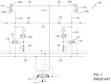
- Such work machines comprise a hydraulic circuit configured to actuate the two boom actuators, which is schematically represented in Figure 1 and is denoted with reference number 100.
- Hydraulic arrangement 100 comprises a valve arrangement 110, which is interposed between a source of pressurized hydraulic fluid 115 and the two boom actuators 120 and is configured to selectively feed a flow of pressurized hydraulic fluid towards the two boom actuators 120, to operate these latter.
- valve arrangement 110 comprises a four-way three-position hydraulic valve configured to selectively put one of the two ends of the boom actuators 110 in fluid communication with the source of pressurized fluid 115.
- one end 120a the boom actuators 120 is fluidly connected to the valve arrangement 110 via first hydraulic lines 130, and the other end 120b of the boom actuators 120 is fluidly connected to the valve arrangement 110 via second hydraulic lines 140.
- first hydraulic lines 130 are also fluidly connected to each other, immediately downstream the two boom actuators 120, via an equalizing hydraulic line 150.
- the equalizing hydraulic line 150 is adapted to balance /equalize the hydraulic pressure of the hydraulic fluid fed towards the two ends 120a of boom actuators 120, to avoid pressure unbalances and therefore unwanted torques exerted by the boom actuators 120 on the same boom.
- the equalizing hydraulic line 150 is further provided with flow restrictors 160, to limit the hydraulic fluid flow in case of rupture of the same equalizing line 150.
- the two flow restrictor 160 are adapted to damp the downward rotation of the boom in the event of a failure in the same equalizing hydraulic line 150.
- the diameter of the flow restrictors 160 is a trade-off between a diameter large enough to allow a fast pressure equilibration between the two hydraulic lines 130 and a diameter small enough to damp the downward rotation of the boom in the event of a failure in the same equalizing hydraulic line 150.
- the hydraulic arrangement 100 comprises two flow control valves 170, which are arranged along first hydraulic line 130, between the valve arrangement 110 and the boom actuators 120 and are configured to be operated to allow to discharge the hydraulic pressure at the first end of the boom actuators 120 and lower the boom accordingly.
- Flow control valves 170 are hydraulically actuated valves and are connected to hydraulic pilot lines 180 to be actuated towards an open position.
- flow control valves 170 comprises biasing means configured to bias these latter towards their closed position, and drain lines 185 configured to drain the spring chamber accommodating the biasing means of discharge valves 170.
- the hydraulic arrangement 100 comprises two pressure relief valves 190, which are arranged along the first hydraulic line 130, in parallel to the flow control valves 170, and are configured to open when the hydraulic pressure at the first end of the boom actuators 120 exceeds a predetermined threshold.
- An aim of the present invention is to satisfy the above-mentioned need in an optimized and cost-effective manner.
- number 1 denotes, as a whole, a work machine, in particular an earth-moving machine such as an excavator, a digger or the like.
- Work machine 1 comprises a body (not illustrated) movable on the ground via ground engaging wheels or tracks, and a hydraulically actuated work implement (not illustrated), which is carried by the body and is configured to perform multiple earth-moving operations.
- the hydraulically actuated work implement comprises a boom rotatably carried by the body of the work machine 1.
- the work implement preferably comprises a stick or dipper or arm rotatably carried by the boom; and a bucket or similar work attachment rotatably carried by the arm.
- work machine 1 comprises a pair of boom actuators 3, which are carried by the body of work vehicle 1, are operatively interposed between the body of the work machine and the boom and are configured to rotate the boom with respect to the body of the work machine 1.
- boom actuators 3 are arranged on opposite sides of the same boom.
- boom actuators 3 preferably comprises double acting hydraulic cylinders.
- work machine 1 further comprises: at least an arm actuator configured to rotate the arm with respect to the boom; and at least one bucket actuator configured to rotate the bucket with respect to the arm.
- work machine 1 further comprises a hydraulic arrangement 4 fluidly connected to boom actuators 3 and configured to actuate these latter, to move the boom accordingly.
- the hydraulic arrangement 4 comprises a valve assembly 6 that is operatively interposed between a source of pressurized hydraulic fluid 7 and the two boom actuators 3.
- Hydraulic arrangement 4 further comprises first hydraulic lines/conduit/pipes 8 fluidly connecting the valve assembly 6 with a first end 3a of boom actuators 3, and second hydraulic lines 10 fluidly connecting the valve assembly 6 with a second end 3b of boom actuators 3, opposite to the first end 3a.
- hydraulic lines 8 comprise a hydraulic line fluidly connected to valve assembly 6 and branching off in two hydraulic lines 8a and 8b respectively connected to the first ends 3a of the two boom actuators 3.
- hydraulic lines 10 comprise a hydraulic line fluidly connected to valve assembly 6 and branching off in two hydraulic lines 10a and 10b respectively connected to the second ends 3b of the two boom actuators 3.
- Valve assembly 6 is adapted to selectively route the pressurized hydraulic fluid provided by the source 7 to one of the two ends 3a or 3b of each boom actuator 3 via hydraulic lines 8 or 10, to operate the boom actuators 3 accordingly.
- valve assembly 6 preferably comprises a four-way three-position hydraulic valve 12.
- valve 12 is selectively connectable to source 7, to a tank 14 and to the two hydraulic lines 8 and 10.
- valve 12 In a first position, the valve 12 prevents fluid communication between the source 7, the tank 14 and the two hydraulic lines 8 and 10. In the second and in the third position, the valve 12 puts the source 7 in fluid communication with hydraulic lines 8 and tank 14 in fluid communication with hydraulic lines 10 and vice-versa, to selectively pressurize the first ends 3a or the second ends 3b of boom actuators 3.
- hydraulic arrangements 4 preferably comprises one or more flow control valves 20, which are arranged along hydraulic lines 8 and are configured to regulate the hydraulic fluid flow between the valve assembly 6 and the boom actuators 3.
- hydraulic arrangement 4 preferably comprises a pair of flow control valves 20 respectively arranged along hydraulic lines 8a and 8b.
- Flow control valve 20 preferably comprises a two-way two-position hydraulic valve, which has a first port connected to valve assembly 6 and a second port connected to the first end 3a of a corresponding boom actuator 3.
- flow control valve 20 In the first position, flow control valve 20 allows only a unidirectional flow of hydraulic fluid from valve assembly 6 to boom actuator 3, i.e. it works as a check valve. In the second position, on the other hand, flow control valve 20 allows a bidirectional flow of hydraulic fluid between valve assembly 6 and boom actuator 3.
- Flow control valve 20 is configured to be normally biased towards the first position.
- hydraulic arrangement 4 comprises a first pilot line 21 which is operatively connected to flow regulation valve 20 and is configured to actuate the same flow regulation valve 20 in the second position.
- first pilot line 21 is also connected to valve assembly 6 and is adapted to actuate the same valve assembly 6 towards its third position, wherein the second end 3b of boom actuator 3 is pressurized.
- hydraulic arrangement 4 comprises also a drain line 22 fluidly connected to tank.
- hydraulic arrangement 4 further comprises a pressure relief valve 23, which is fluidly connected to hydraulic line 8 and is configured to open when the hydraulic pressure at the first end 3a of boom actuator 3 exceeds a certain threshold, to discharge the hydraulic pressure at the first end 3a of boom actuator 3.
- hydraulic arrangement 4 comprises a pair of pressure relief valves 23, respectively fluidly connected to the hydraulic lines 8a and 8b.
- hydraulic arrangement 4 preferably comprises hydraulic filtering devices 24 arranged immediately upstream the pressure relief valves 23, between pressure relief valves 23 and the boom actuators 3.
- pressure relief valve 23 is fluidly connected, on one side to the portion of hydraulic line 8a comprised between pressure regulating valve 20 and boom actuator 3, and on the other side, to first hydraulic pilot line 21.
- pressure relief valve 23 is preferably configured to open when the pressure within the portion of hydraulic line 8a comprised between pressure regulating valve 20 and boom actuator 3 exceeds, by a predetermined overpressure, the pressure within first hydraulic pilot line 21.
- first hydraulic pilot line 21 further comprises a flow restrictor 26 and a check valve 28, arranged in parallel to each other upstream the flow control valve 20 and the pressure relief valve 23.
- Check valve 28 is configured to allow the hydraulic fluid to flow only towards the flow control valve 20.
- the flow restrictor 26, is configured to damp the flow of hydraulic fluid coming from the pressure relief valve 23, when this latter open for instance due to a pressure spike at the boom actuator 3.
- hydraulic arrangement 4 further comprises an equalizing hydraulic line 30, which is adapted to fluidly connect the two hydraulic lines 8 to each other.
- equalizing hydraulic line 30 is fluidly connected between lines 8a and 8b, to fluidly connect the two ends 3a of boom actuators 3.
- Equalizing hydraulic line 30 is preferably fluidly connected to the two hydraulic lines 8a and 8b, preferably downstream the two flow control valves 20, i.e. between the same flow control valves 20 and the boom actuators 3.
- equalizing hydraulic line 30 is adapted to equalize/balance the hydraulic pressure at the two ends 3a of the two boom actuators 3, in order to avoid pressure unbalances at the ends 3a of the two boom actuators 3 when rotating the boom upwards, so as to unwanted torques exerted on the same boom.
- equalizing hydraulic line 30 is provided with at least one flow regulating valve 32, which is adapted to control the flow of hydraulic fluid within the same equalizing hydraulic line 30.
- flow regulating valve 32 is preferably configured to selectively allow at least two different levels of flowrate within the same equalizing hydraulic line 30.
- flow regulating valve 32 is preferably operable between a first position in which it limits/reduces/ restricts the flowrate of the hydraulic fluid within the same equalizing hydraulic line 30, and a second position in which it allows the flow of the hydraulic fluid within the equalizing hydraulic line 30, i.e. it does not limit/reduce/ restrict the flowrate of the hydraulic fluid within the same equalizing hydraulic line 30.
- flow regulating valve 32 is configured to be biased in its first position.
- flow regulating valve 32 in its first position, substantially obstructs equalizing hydraulic line 32.
- flow regulating valve 32 is preferably a two-way two position valve 32.
- the two ports of valve 32 are respectively connected to the ends 3a of the two boom actuators 3.
- valve 32 in the first position, is configured to limit the flow of hydraulic fluid within the equalization hydraulic line 30. In other words, in the first position the valve 32 operates as a flow restrictor.
- valve 32 is configured to allow the flow of hydraulic fluid within the equalization hydraulic line 30.
- valve 32 comprises biasing means, such as elastic means, configured to bias the same valve 32 towards its first position.
- hydraulic arrangement 4 comprises two flow regulating valves 32 arranged along equalizing hydraulic line 30, wherein one flow regulating valve 32 is preferably directly fluidly connected to end 3a of one boom actuator 3 and the other flow regulating valve 32 is directly fluidly connected to end 3a of the other boom actuator 3.
- hydraulic arrangement preferably comprises at least one pilot line 36, which is fluidly connected to hydraulic line 8, is operatively connected to flow regulating valve 32 and is adapted to arrange the same flow regulating valve 32 in its second position.
- hydraulic pilot line 36 is fluidly connected to line 8 immediately downstream valve arrangement 6.
- valve assembly 6 when valve assembly 6 is arranged in its second position, to pressurize hydraulic lines 8 and ends 3a of boom actuators 3, flow regulating valve 34 is arranged in its second operative position.
- hydraulic arrangement 4 preferably comprises a pair of hydraulic pilot lines 36, each operatively connected to a corresponding hydraulic regulating valve 32.
- hydraulic drain line 22 is operatively connected also to flow regulating valve 32, and is configured to drain the spring chamber housing the biasing means of the flow regulating valve 32.
- hydraulic arrangement 4 preferably comprises a shuttle valve 40 operatively interposed between hydraulic line 8, hydraulic pilot line 21 and hydraulic pilot line 36.
- shuttle valve 40 has preferably a first port 40a fluidly connected to hydraulic line 8, a second port 40b fluidly connected to hydraulic pilot line 21 and a third port 40c fluidly connected to hydraulic pilot line 36.
- second port 40b of shuttle valve 40 is preferably fluidly connected to hydraulic pilot line 21 immediately downstream flow restrictor 26 and check valve 28, i.e. between flow restrictor 26, check valve 28 and pressure relief valve 23.
- Shuttle valve 40 is preferably configured to put hydraulic line 8 in fluid communication with hydraulic pilot line 36 and fluidly isolate hydraulic pilot line 21 when the pressure within hydraulic pilot line 8 is greater than the pressure within pilot lines 21, i.e. when valve assembly 6 is actuated in its second position to pressurize ends 3a of boom actuators 3 and rotate upwards the same boom. Therefore, in such operative condition, hydraulic pilot line 36 is pressurized to arrange hydraulic regulating valve 32 in its second position.
- shuttle valve 40 is preferably configured to put hydraulic pilot line 21 in fluid communication with hydraulic pilot line 36 and fluidly isolate hydraulic line 8. This operative condition occurs when pressure relief valve 23 opens and hydraulic pilot line 8 is not pressurized by valve assembly 6.
- valve arrangement 6 To rotate upwards the boom, valve arrangement 6 is actuated in its second position and the hydraulic line 8 is pressurized. Accordingly, a flow of pressurized hydraulic fluid is fed to the two ends 3a of the two boom actuators 3.
- hydraulic pilot line 36 is pressurized by hydraulic line 8 and flow regulating valve 32 is arranged in its second position.
- valve assembly 6 is actuated in its third position and the hydraulic line 10 is pressurized. Accordingly, a flow of pressurized hydraulic fluid is fed to the two ends 3b of the two boom actuators 3.
- the flow regulating valve 32 would be arranged in its first position and it will strongly limit or nullify the flow of hydraulic fluid from the hydraulic line 30, to counteract the uncontrolled drop of the boom.
- the provision of the flow regulating valves 32 on the equalizing hydraulic line 30 allows to massively increase the safety of the same hydraulic arrangement, way beyond the minimum safety requirements required by ISO 8643 regulatory for the equalization and signal lines.
- the provision of the flow regulating valve 32 improves the dynamic of the hydraulic arrangement 4, as the size of the orifice of the flow regulating valve 32 in its second position is larger than the diameter of the flow restrictor 160 known in the art, and this reduces the pressure losses localized on such component and the equalizing timing.
- Figure 3 illustrates a work vehicle 200 which is similar to work vehicle 1 and whose corresponding parts will be denoted with the same reference numbers as work vehicle 1.
- Work vehicle 200 distinguishes from work vehicle 1 in that the second port 40b of shuttle valve 40 is not fluidly connected to hydraulic pilot line 21 immediately downstream flow restrictor 26 and check valve 28, but upstream flow restrictor 26 and check valve 28.
- Figure 4 illustrates a further embodiment of work vehicle 1 denoted by reference number 300, which is similar to work vehicle 1 and whose corresponding parts will be denoted with the same reference numbers as work vehicle 1.
- Work vehicle 300 distinguishes from work vehicle 1 in that it is not provided with the shuttle valve 40, and in that the hydraulic pilot line 36 is directly fluidly connected to hydraulic pilot line 21, upstream flow restrictor 26 and check valve 28.
- Figure 5 illustrates a further embodiment of work vehicle 1 denoted by reference number 400, which is similar to work vehicle 1 and whose corresponding parts will be denoted with the same reference numbers as work vehicle 1.
- Work vehicle 400 distinguishes from work vehicle 1 in that it is not provided with the shuttle valve 40, and in that the hydraulic pilot line 36 is directly fluidly connected to hydraulic pilot line 21 immediately downstream flow restrictor 26 and check valve 28, i.e. between flow restrictor 26, check valve 28 and pressure relief valve 21.
- valve 32 in its second position, the hydraulic pressure within pilot line 21 needs to overcome the biasing force applied by the biasing means of valve 32, independently from the pressure within hydraulic line 8.
- Figure 6 illustrates a further embodiment of work vehicle 1 denoted by reference number 500, which is similar to work vehicle 1 and whose corresponding parts will be denoted with the same reference numbers as work vehicle 1.
- Work vehicle 500 distinguishes from work vehicle 1 in that it is not provided with the shuttle valve 40, and in that the hydraulic pilot line 36 is directly fluidly connected to hydraulic line 8.
- valve 32 is arranged in its second position, i.e. it is opened, when valve 12 is arranged in its second position to pressurize hydraulic line 8.
Landscapes
- Engineering & Computer Science (AREA)
- Mining & Mineral Resources (AREA)
- Civil Engineering (AREA)
- General Engineering & Computer Science (AREA)
- Structural Engineering (AREA)
- Fluid-Pressure Circuits (AREA)
- Operation Control Of Excavators (AREA)
Abstract
Description
- The present invention relates to a hydraulic arrangement for a hydraulically actuated boom of a work machine, in particular of an earth-moving machine such as an excavator, a digger or the like. The present invention further relates to a work machine comprising such hydraulic arrangement.
- The present invention finds its preferred, although not exclusive, application in a hydraulic arrangement for controlling the lowering of the hydraulically actuated boom of a work machine. Reference will be made to this application by way of the example below, without however losing in generality.
- As is known, work machines such as excavators, diggers, and the like are provided with a hydraulically actuated work implement carried by a body of the work machine and configured to perform multiple earth-moving operations.
- In particular, said hydraulic actuated work implement comprises: a boom rotatably carried by the body of the work machine; a stick or dipper or arm rotatably carried by the boom; a bucket or similar work attachment rotatably carried by the stick; and a plurality of actuators adapted to rotate the boom, the arm, and the bucket with respect to their hinge points.
- In particular, the afore-mentioned actuators comprise a pair of boom actuators, such as double acting hydraulic cylinders, which are operatively interposed between the body of the work machine and the boom, are arranged on opposite sides of the same boom, and are configured to rotate the boom with respect to the body of the work machine.
- In addition, such work machines comprise a hydraulic circuit configured to actuate the two boom actuators, which is schematically represented in
Figure 1 and is denoted withreference number 100. -
Hydraulic arrangement 100 comprises avalve arrangement 110, which is interposed between a source of pressurizedhydraulic fluid 115 and the twoboom actuators 120 and is configured to selectively feed a flow of pressurized hydraulic fluid towards the twoboom actuators 120, to operate these latter. - More in detail, the
valve arrangement 110 comprises a four-way three-position hydraulic valve configured to selectively put one of the two ends of theboom actuators 110 in fluid communication with the source of pressurizedfluid 115. - In particular, one
end 120a theboom actuators 120 is fluidly connected to thevalve arrangement 110 via firsthydraulic lines 130, and theother end 120b of theboom actuators 120 is fluidly connected to thevalve arrangement 110 via secondhydraulic lines 140. - By pressurizing the first
hydraulic lines 130, the boom is lifted and by pressurizing the secondhydraulic lines 140 the boom is lowered. - In addition, the first
hydraulic lines 130 are also fluidly connected to each other, immediately downstream the twoboom actuators 120, via an equalizinghydraulic line 150. The equalizinghydraulic line 150 is adapted to balance /equalize the hydraulic pressure of the hydraulic fluid fed towards the twoends 120a ofboom actuators 120, to avoid pressure unbalances and therefore unwanted torques exerted by theboom actuators 120 on the same boom. - Pursuant ISO 8643 regulatory, the equalizing
hydraulic line 150 is further provided withflow restrictors 160, to limit the hydraulic fluid flow in case of rupture of the same equalizingline 150. - The two
flow restrictor 160, in particular, are adapted to damp the downward rotation of the boom in the event of a failure in the same equalizinghydraulic line 150. - However, the diameter of the
flow restrictors 160 is a trade-off between a diameter large enough to allow a fast pressure equilibration between the twohydraulic lines 130 and a diameter small enough to damp the downward rotation of the boom in the event of a failure in the same equalizinghydraulic line 150. - In addition, the
hydraulic arrangement 100 comprises twoflow control valves 170, which are arranged along firsthydraulic line 130, between thevalve arrangement 110 and theboom actuators 120 and are configured to be operated to allow to discharge the hydraulic pressure at the first end of theboom actuators 120 and lower the boom accordingly. -
Flow control valves 170 are hydraulically actuated valves and are connected tohydraulic pilot lines 180 to be actuated towards an open position. - In addition,
flow control valves 170 comprises biasing means configured to bias these latter towards their closed position, anddrain lines 185 configured to drain the spring chamber accommodating the biasing means ofdischarge valves 170. - Moreover, the
hydraulic arrangement 100 comprises twopressure relief valves 190, which are arranged along the firsthydraulic line 130, in parallel to theflow control valves 170, and are configured to open when the hydraulic pressure at the first end of theboom actuators 120 exceeds a predetermined threshold. - As said above, work machines field is subjected to the ISO 8643 regulatory, which set the safety criterions that the aforementioned work machine must satisfy.
- In particular, for the equalizing
hydraulic line 150, such regulation provides only for a test in static conditions and without load, and it does not provide for any dynamic test or test simulating the rupture of this equalizingline 150. Therefore, the above-described current arrangement satisfies the safety criterions set out by ISO 8643. - However, according to the actual
hydraulic arrangement 100, should the equalizationhydraulic line 150 break, the boom would rotate downwards uncontrollably. This clearly entails relevant safety problems for the operators working nearby the work machine. - In view of the above, the need is felt to increase the safety of the hydraulically actuated arm of a work machine.
- An aim of the present invention is to satisfy the above-mentioned need in an optimized and cost-effective manner.
- The aforementioned aims are reached by a hydraulic arrangement and by a work machine as claimed in the appended set of claims.
- For a better understanding of the present invention, a preferred embodiment is described in the following, by way of a non-limiting example, with reference to the attached drawings, wherein:
-
Figure 1 illustrates a hydraulic arrangement for a hydraulically actuated boom of a work machine as known in the art; and -
Figures 2-6 illustrates as many embodiments of a work machine realized according to the present invention. - With reference to
Figure 2 ,number 1 denotes, as a whole, a work machine, in particular an earth-moving machine such as an excavator, a digger or the like. -
Work machine 1 comprises a body (not illustrated) movable on the ground via ground engaging wheels or tracks, and a hydraulically actuated work implement (not illustrated), which is carried by the body and is configured to perform multiple earth-moving operations. - As known, the hydraulically actuated work implement comprises a boom rotatably carried by the body of the
work machine 1. - In addition, the work implement preferably comprises a stick or dipper or arm rotatably carried by the boom; and a bucket or similar work attachment rotatably carried by the arm.
- Moreover,
work machine 1 comprises a pair of boom actuators 3, which are carried by the body ofwork vehicle 1, are operatively interposed between the body of the work machine and the boom and are configured to rotate the boom with respect to the body of thework machine 1. Preferably, boom actuators 3 are arranged on opposite sides of the same boom. In particular, boom actuators 3 preferably comprises double acting hydraulic cylinders. - Preferably,
work machine 1 further comprises: at least an arm actuator configured to rotate the arm with respect to the boom; and at least one bucket actuator configured to rotate the bucket with respect to the arm. - With reference to the exemplary embodiment illustrated in
Figure 2 ,work machine 1 further comprises a hydraulic arrangement 4 fluidly connected to boom actuators 3 and configured to actuate these latter, to move the boom accordingly. - In particular, the hydraulic arrangement 4 comprises a valve assembly 6 that is operatively interposed between a source of pressurized
hydraulic fluid 7 and the two boom actuators 3. - Hydraulic arrangement 4 further comprises first hydraulic lines/conduit/
pipes 8 fluidly connecting the valve assembly 6 with afirst end 3a of boom actuators 3, and secondhydraulic lines 10 fluidly connecting the valve assembly 6 with asecond end 3b of boom actuators 3, opposite to thefirst end 3a. - In particular,
hydraulic lines 8 comprise a hydraulic line fluidly connected to valve assembly 6 and branching off in twohydraulic lines first ends 3a of the two boom actuators 3. - Similarly,
hydraulic lines 10 comprise a hydraulic line fluidly connected to valve assembly 6 and branching off in twohydraulic lines second ends 3b of the two boom actuators 3. - Valve assembly 6 is adapted to selectively route the pressurized hydraulic fluid provided by the
source 7 to one of the twoends hydraulic lines - In particular, by pressurizing
hydraulic lines 8, the boom actuators 3 rotates upwards the boom, while by pressurizinghydraulic lines 10, the boom actuators 3 rotates downwards the boom. - With reference to the exemplary embodiment illustrated in
Figure 2 , valve assembly 6 preferably comprises a four-way three-positionhydraulic valve 12. - Preferably, the four ports of
valve 12 are selectively connectable tosource 7, to atank 14 and to the twohydraulic lines - In a first position, the
valve 12 prevents fluid communication between thesource 7, thetank 14 and the twohydraulic lines valve 12 puts thesource 7 in fluid communication withhydraulic lines 8 andtank 14 in fluid communication withhydraulic lines 10 and vice-versa, to selectively pressurize thefirst ends 3a or thesecond ends 3b of boom actuators 3. - With reference to the exemplary embodiment illustrated in
Figure 2 , in addition, hydraulic arrangements 4 preferably comprises one or moreflow control valves 20, which are arranged alonghydraulic lines 8 and are configured to regulate the hydraulic fluid flow between the valve assembly 6 and the boom actuators 3. - More in detail, hydraulic arrangement 4 preferably comprises a pair of
flow control valves 20 respectively arranged alonghydraulic lines -
Flow control valve 20 preferably comprises a two-way two-position hydraulic valve, which has a first port connected to valve assembly 6 and a second port connected to thefirst end 3a of a corresponding boom actuator 3. - In the first position,
flow control valve 20 allows only a unidirectional flow of hydraulic fluid from valve assembly 6 to boom actuator 3, i.e. it works as a check valve. In the second position, on the other hand,flow control valve 20 allows a bidirectional flow of hydraulic fluid between valve assembly 6 and boom actuator 3. -
Flow control valve 20 is configured to be normally biased towards the first position. - In addition, hydraulic arrangement 4 comprises a
first pilot line 21 which is operatively connected toflow regulation valve 20 and is configured to actuate the sameflow regulation valve 20 in the second position. - Preferably,
first pilot line 21 is also connected to valve assembly 6 and is adapted to actuate the same valve assembly 6 towards its third position, wherein thesecond end 3b of boom actuator 3 is pressurized. - With reference to the exemplary embodiment illustrated in
Figure 2 , hydraulic arrangement 4 comprises also adrain line 22 fluidly connected to tank. - With reference to the exemplary embodiment illustrated in
Figure 2 , hydraulic arrangement 4 further comprises apressure relief valve 23, which is fluidly connected tohydraulic line 8 and is configured to open when the hydraulic pressure at thefirst end 3a of boom actuator 3 exceeds a certain threshold, to discharge the hydraulic pressure at thefirst end 3a of boom actuator 3. - Preferably, hydraulic arrangement 4 comprises a pair of
pressure relief valves 23, respectively fluidly connected to thehydraulic lines - In addition, hydraulic arrangement 4 preferably comprises
hydraulic filtering devices 24 arranged immediately upstream thepressure relief valves 23, betweenpressure relief valves 23 and the boom actuators 3. - In addition, with reference to the exemplary embodiment illustrated in
Figure 2 ,pressure relief valve 23 is fluidly connected, on one side to the portion ofhydraulic line 8a comprised betweenpressure regulating valve 20 and boom actuator 3, and on the other side, to firsthydraulic pilot line 21. - In particular,
pressure relief valve 23 is preferably configured to open when the pressure within the portion ofhydraulic line 8a comprised betweenpressure regulating valve 20 and boom actuator 3 exceeds, by a predetermined overpressure, the pressure within firsthydraulic pilot line 21. - With reference to the exemplary embodiment illustrated in
Figure 2 , firsthydraulic pilot line 21 further comprises aflow restrictor 26 and acheck valve 28, arranged in parallel to each other upstream theflow control valve 20 and thepressure relief valve 23. - Check
valve 28 is configured to allow the hydraulic fluid to flow only towards theflow control valve 20. The flow restrictor 26, on the other hand, is configured to damp the flow of hydraulic fluid coming from thepressure relief valve 23, when this latter open for instance due to a pressure spike at the boom actuator 3. - With reference to the exemplary embodiment illustrated in
Figure 2 , hydraulic arrangement 4 further comprises an equalizinghydraulic line 30, which is adapted to fluidly connect the twohydraulic lines 8 to each other. - In particular, the equalizing
hydraulic line 30 is fluidly connected betweenlines ends 3a of boom actuators 3. - Equalizing
hydraulic line 30 is preferably fluidly connected to the twohydraulic lines flow control valves 20, i.e. between the sameflow control valves 20 and the boom actuators 3. - In particular, equalizing
hydraulic line 30 is adapted to equalize/balance the hydraulic pressure at the twoends 3a of the two boom actuators 3, in order to avoid pressure unbalances at theends 3a of the two boom actuators 3 when rotating the boom upwards, so as to unwanted torques exerted on the same boom. - With reference to the exemplary embodiment illustrated in
Figure 2 , equalizinghydraulic line 30 is provided with at least oneflow regulating valve 32, which is adapted to control the flow of hydraulic fluid within the same equalizinghydraulic line 30. - In particular,
flow regulating valve 32 is preferably configured to selectively allow at least two different levels of flowrate within the same equalizinghydraulic line 30. - More in detail,
flow regulating valve 32 is preferably operable between a first position in which it limits/reduces/ restricts the flowrate of the hydraulic fluid within the same equalizinghydraulic line 30, and a second position in which it allows the flow of the hydraulic fluid within the equalizinghydraulic line 30, i.e. it does not limit/reduce/ restrict the flowrate of the hydraulic fluid within the same equalizinghydraulic line 30. - Preferably,
flow regulating valve 32 is configured to be biased in its first position. - In even more detail, in its first position, preferably flow regulating
valve 32 substantially obstructs equalizinghydraulic line 32. - With reference to the exemplary embodiment illustrated in
Figure 2 ,flow regulating valve 32 is preferably a two-way twoposition valve 32. The two ports ofvalve 32 are respectively connected to theends 3a of the two boom actuators 3. - Accordingly, in the first position,
valve 32 is configured to limit the flow of hydraulic fluid within the equalizationhydraulic line 30. In other words, in the first position thevalve 32 operates as a flow restrictor. - In the second position, on the other hand,
valve 32 is configured to allow the flow of hydraulic fluid within the equalizationhydraulic line 30. - In addition,
valve 32 comprises biasing means, such as elastic means, configured to bias thesame valve 32 towards its first position. - Preferably, hydraulic arrangement 4 comprises two
flow regulating valves 32 arranged along equalizinghydraulic line 30, wherein oneflow regulating valve 32 is preferably directly fluidly connected to end 3a of one boom actuator 3 and the otherflow regulating valve 32 is directly fluidly connected to end 3a of the other boom actuator 3. - With reference to the exemplary embodiment illustrated in
Figure 2 , hydraulic arrangement preferably comprises at least onepilot line 36, which is fluidly connected tohydraulic line 8, is operatively connected to flow regulatingvalve 32 and is adapted to arrange the sameflow regulating valve 32 in its second position. - Preferably,
hydraulic pilot line 36 is fluidly connected toline 8 immediately downstream valve arrangement 6. - As a consequence, when valve assembly 6 is arranged in its second position, to pressurize
hydraulic lines 8 and ends 3a of boom actuators 3, flow regulating valve 34 is arranged in its second operative position. - More in detail, hydraulic arrangement 4 preferably comprises a pair of
hydraulic pilot lines 36, each operatively connected to a corresponding hydraulic regulatingvalve 32. - With reference to the exemplary embodiment illustrated in
Figure 2 ,hydraulic drain line 22 is operatively connected also to flow regulatingvalve 32, and is configured to drain the spring chamber housing the biasing means of theflow regulating valve 32. - With reference to the exemplary embodiment illustrated in
Figure 2 , hydraulic arrangement 4 preferably comprises ashuttle valve 40 operatively interposed betweenhydraulic line 8,hydraulic pilot line 21 andhydraulic pilot line 36. - More in detail,
shuttle valve 40 has preferably afirst port 40a fluidly connected tohydraulic line 8, asecond port 40b fluidly connected tohydraulic pilot line 21 and athird port 40c fluidly connected tohydraulic pilot line 36. - In particular,
second port 40b ofshuttle valve 40 is preferably fluidly connected tohydraulic pilot line 21 immediatelydownstream flow restrictor 26 andcheck valve 28, i.e. betweenflow restrictor 26,check valve 28 andpressure relief valve 23. -
Shuttle valve 40 is preferably configured to puthydraulic line 8 in fluid communication withhydraulic pilot line 36 and fluidly isolatehydraulic pilot line 21 when the pressure withinhydraulic pilot line 8 is greater than the pressure withinpilot lines 21, i.e. when valve assembly 6 is actuated in its second position to pressurizeends 3a of boom actuators 3 and rotate upwards the same boom. Therefore, in such operative condition,hydraulic pilot line 36 is pressurized to arrange hydraulic regulatingvalve 32 in its second position. - On the other hand, when pressure within
hydraulic pilot line 21 is greater than the pressure withinhydraulic line 8,shuttle valve 40 is preferably configured to puthydraulic pilot line 21 in fluid communication withhydraulic pilot line 36 and fluidly isolatehydraulic line 8. This operative condition occurs whenpressure relief valve 23 opens andhydraulic pilot line 8 is not pressurized by valve assembly 6. - The operation of the above-described hydraulic arrangement 4 is easily inferable from the above, and it will be briefly described in the following.
- To rotate upwards the boom, valve arrangement 6 is actuated in its second position and the
hydraulic line 8 is pressurized. Accordingly, a flow of pressurized hydraulic fluid is fed to the twoends 3a of the two boom actuators 3. - At the same time,
hydraulic pilot line 36 is pressurized byhydraulic line 8 and flow regulatingvalve 32 is arranged in its second position. - To rotate downwards the boom, on the other hand, valve assembly 6 is actuated in its third position and the
hydraulic line 10 is pressurized. Accordingly, a flow of pressurized hydraulic fluid is fed to the twoends 3b of the two boom actuators 3. - In addition, should the equalizing
hydraulic line 30 break when the boom is lifted and the valve assembly 6 is not actuated, so that no pressurized hydraulic fluid is fed towards the boom actuators 3, theflow regulating valve 32 would be arranged in its first position and it will strongly limit or nullify the flow of hydraulic fluid from thehydraulic line 30, to counteract the uncontrolled drop of the boom. - In view of the foregoing, the advantages of a hydraulic arrangement 4 according to the present invention are apparent.
- In particular, the provision of the
flow regulating valves 32 on the equalizinghydraulic line 30 allows to massively increase the safety of the same hydraulic arrangement, way beyond the minimum safety requirements required by ISO 8643 regulatory for the equalization and signal lines. - Therefore, it is apparent that, in the event of a modification of the ISO 8643 regulatory setting stricter safety requirement, the proposed hydraulic arrangement 4 would already be able to meet such safety requirements.
- In addition, the provision of the
flow regulating valve 32 improves the dynamic of the hydraulic arrangement 4, as the size of the orifice of theflow regulating valve 32 in its second position is larger than the diameter of theflow restrictor 160 known in the art, and this reduces the pressure losses localized on such component and the equalizing timing. - It is clear that modifications can be made to the described hydraulic arrangement 4, which do not extend beyond the scope of protection defined by the claims.
- For instance,
Figure 3 illustrates awork vehicle 200 which is similar to workvehicle 1 and whose corresponding parts will be denoted with the same reference numbers aswork vehicle 1. -
Work vehicle 200 distinguishes fromwork vehicle 1 in that thesecond port 40b ofshuttle valve 40 is not fluidly connected tohydraulic pilot line 21 immediatelydownstream flow restrictor 26 andcheck valve 28, butupstream flow restrictor 26 andcheck valve 28. - In addition,
Figure 4 illustrates a further embodiment ofwork vehicle 1 denoted byreference number 300, which is similar to workvehicle 1 and whose corresponding parts will be denoted with the same reference numbers aswork vehicle 1. -
Work vehicle 300 distinguishes fromwork vehicle 1 in that it is not provided with theshuttle valve 40, and in that thehydraulic pilot line 36 is directly fluidly connected tohydraulic pilot line 21,upstream flow restrictor 26 andcheck valve 28. -
Figure 5 illustrates a further embodiment ofwork vehicle 1 denoted byreference number 400, which is similar to workvehicle 1 and whose corresponding parts will be denoted with the same reference numbers aswork vehicle 1. -
Work vehicle 400 distinguishes fromwork vehicle 1 in that it is not provided with theshuttle valve 40, and in that thehydraulic pilot line 36 is directly fluidly connected tohydraulic pilot line 21 immediatelydownstream flow restrictor 26 andcheck valve 28, i.e. betweenflow restrictor 26,check valve 28 andpressure relief valve 21. - Therefore, according to the embodiments illustrated in
Figures 4 and5 , to arrangevalve 32 in its second position, the hydraulic pressure withinpilot line 21 needs to overcome the biasing force applied by the biasing means ofvalve 32, independently from the pressure withinhydraulic line 8. - Lastly,
Figure 6 illustrates a further embodiment ofwork vehicle 1 denoted byreference number 500, which is similar to workvehicle 1 and whose corresponding parts will be denoted with the same reference numbers aswork vehicle 1. -
Work vehicle 500 distinguishes fromwork vehicle 1 in that it is not provided with theshuttle valve 40, and in that thehydraulic pilot line 36 is directly fluidly connected tohydraulic line 8. - Therefore, in this last embodiment,
valve 32 is arranged in its second position, i.e. it is opened, whenvalve 12 is arranged in its second position to pressurizehydraulic line 8.
Claims (10)
- A hydraulic arrangement (4) for a hydraulically actuated boom of a work machine (1);said work machine (1) comprising a body carrying said boom in a rotatable manner, and a pair of boom actuators (3), which are interposed between said body and said boom and are configured to rotate said boom with respect to said body;said hydraulic arrangement (4) being adapted to be fluidly connected to said boom actuators (3) and being configured to actuate said boom actuators (3), in order to rotate said boom;said hydraulic arrangement (4) comprising:• a valve assembly (6) adapted to be operatively interposed between a source of pressurized hydraulic fluid (7) and said boom actuators (3);• first hydraulic lines (8) adapted to fluidly connect said valve assembly (6) with a first end (3a) of said boom actuators (3);• second hydraulic lines (10) adapted to fluidly connect said valve assembly (6) with a second end (3b) of said boom actuators (3), opposite to said first end (3a);• an equalizing hydraulic line (30) fluidly connecting said first hydraulic lines (8) to each other, upstream said boom actuators (3); and• at least one flow regulating valve (32) arranged along said equalizing hydraulic line (30) and configured to regulate the flow of said hydraulic fluid within said equalizing hydraulic line (30).
- Hydraulic arrangement according to claim 1, wherein said flow regulating valve (32) is operable between a first position, in which it restricts the flowrate of the hydraulic fluid within said equalizing hydraulic line (30), and a second position in which it does not restrict the flowrate of the hydraulic fluid within said equalizing hydraulic line (30).
- Hydraulic arrangement according to claim 1 or 2, comprising a pair of said flow regulating valves (32) arranged along said equalizing hydraulic line (30), wherein one of said flow regulating valve (32) is directly fluidly connected to said first end (3a) of one of said boom actuators (3) and the other of said flow regulating valves (32) is directly fluidly connected to said first end (3a) of the other of said boom actuators (3).
- Hydraulic arrangement according to claim 2 or 3, further comprising a first hydraulic pilot line (36), which is fluidly connected to said hydraulic line (8), is operatively connected to said flow regulating valve (32) and is adapted to actuate said flow regulating valve (32) in said second position.
- Hydraulic arrangement according to claim 2, 3 or 4, wherein said flow regulating valve (32) is configured to be biased in said first position.
- Hydraulic arrangement according to any of claim from 2 to 5, further comprising biasing means, which are adapted to bias said flow regulating valve (32) in said first position.
- Hydraulic arrangement according to claim 4, 5 or 6, further comprising a flow control valve (20) arranged along said first hydraulic line (8) and configured to control the flow of said hydraulic fluid within said first hydraulic line (8) ;
said hydraulic arrangement (4) further comprising a third pilot line (21) adapted to actuate said flow control valve (20) . - Hydraulic arrangement according to claim 7, further comprising a shuttle valve (40), which is operatively interposed between said hydraulic line (8), said first pilot line (36) and said third pilot line (21).
- Hydraulic arrangement according to claim 8, wherein said shuttle valve (40) is configured to:
put said hydraulic line (8) in fluid communication with said first hydraulic pilot line (36) and to fluidly isolate said third hydraulic pilot line (21) when the pressure within hydraulic pilot line (8) is greater than the pressure within said third pilot line (21); and
put said third hydraulic pilot line (21) in fluid communication with said first hydraulic pilot line (36), and to fluidly isolate said hydraulic line (8) when the pressure within said third hydraulic pilot line (21) is greater than the pressure within said hydraulic line (8). - Work machine (1, 200, 300) comprising a body movable of the ground by means of ground engaging means and a hydraulically actuated work implement carried by said body;
said hydraulically actuated work implement comprising: a boom rotatably carried by said body; a pair of boom actuators (3) configured to rotate said boom with respect to said body; an arm rotatably carried by said boom; an arm actuator configured to rotate said arm with respect to said boom; a bucket rotatably carried by said arm; and a bucket actuator configured to rotate said bucket with respect to said arm;
said working machine further comprising a hydraulic arrangement (4) realized according to any of the preceding claims.
Applications Claiming Priority (1)
| Application Number | Priority Date | Filing Date | Title |
|---|---|---|---|
| IT102023000010215A IT202300010215A1 (en) | 2023-05-19 | 2023-05-19 | IMPROVED HYDRAULIC SYSTEM FOR A HYDRAULIC POWERED ARM OF A WORK MACHINERY |
Publications (1)
| Publication Number | Publication Date |
|---|---|
| EP4464847A1 true EP4464847A1 (en) | 2024-11-20 |
Family
ID=87281103
Family Applications (1)
| Application Number | Title | Priority Date | Filing Date |
|---|---|---|---|
| EP24176747.4A Pending EP4464847A1 (en) | 2023-05-19 | 2024-05-17 | Improved hydraulic arrangement for a hydraulically actuated boom of a work machine |
Country Status (2)
| Country | Link |
|---|---|
| EP (1) | EP4464847A1 (en) |
| IT (1) | IT202300010215A1 (en) |
Citations (2)
| Publication number | Priority date | Publication date | Assignee | Title |
|---|---|---|---|---|
| GB2055977A (en) * | 1979-07-26 | 1981-03-11 | Fiat Allis Construct Machine | Hydraulic control systems |
| US20100275771A1 (en) * | 2009-04-29 | 2010-11-04 | Liebherr-France Sas | Hydraulic System and Mobile Construction Machine |
-
2023
- 2023-05-19 IT IT102023000010215A patent/IT202300010215A1/en unknown
-
2024
- 2024-05-17 EP EP24176747.4A patent/EP4464847A1/en active Pending
Patent Citations (2)
| Publication number | Priority date | Publication date | Assignee | Title |
|---|---|---|---|---|
| GB2055977A (en) * | 1979-07-26 | 1981-03-11 | Fiat Allis Construct Machine | Hydraulic control systems |
| US20100275771A1 (en) * | 2009-04-29 | 2010-11-04 | Liebherr-France Sas | Hydraulic System and Mobile Construction Machine |
Also Published As
| Publication number | Publication date |
|---|---|
| IT202300010215A1 (en) | 2024-11-19 |
Similar Documents
| Publication | Publication Date | Title |
|---|---|---|
| US7104181B2 (en) | Hydraulic control circuit for a hydraulic lifting cylinder | |
| KR100228810B1 (en) | Hydraulics for Construction Equipment | |
| JP5265078B2 (en) | Hydraulic system with flow regulator | |
| JP5297187B2 (en) | Hydraulic system with pressure compensator | |
| EP1630303B1 (en) | Hydraulic drive device | |
| US7140178B2 (en) | Hydraulic arrangement | |
| US7127888B2 (en) | Hydraulic drive unit | |
| JPH03189407A (en) | Automatic pressure release device for hydraulic motor | |
| EP1088995A1 (en) | Hydraulic circuit device | |
| CN109563695B (en) | Control valve for excavator and excavator | |
| US20200199842A1 (en) | Boom Control System For A Construction Machine | |
| EP2910796B1 (en) | Assembly with a control valve device with a float position | |
| US11885099B2 (en) | Drift-prevention valve device, blade device, and working machine | |
| CN105899816B (en) | The control system of working rig | |
| GB2319565A (en) | Hydraulic system for working cylinders of construction equipment | |
| JP6286216B2 (en) | Work machine control system and low pressure selection circuit | |
| EP1657213B1 (en) | Ride control system | |
| KR102263246B1 (en) | Excavator boom/arm emergency lowering with safety lock function with logic valve | |
| US10208457B2 (en) | Working machine control system | |
| US7117670B2 (en) | Control device | |
| KR200257578Y1 (en) | A flow rate controlling apparatus for operating boom of an excavator | |
| EP4729701A1 (en) | Improved work machine and control method thereof | |
| EP4660381A1 (en) | Improved work machine and control method thereof | |
| GB2055977A (en) | Hydraulic control systems | |
| IT202300010215A1 (en) | IMPROVED HYDRAULIC SYSTEM FOR A HYDRAULIC POWERED ARM OF A WORK MACHINERY |
Legal Events
| Date | Code | Title | Description |
|---|---|---|---|
| PUAI | Public reference made under article 153(3) epc to a published international application that has entered the european phase |
Free format text: ORIGINAL CODE: 0009012 |
|
| STAA | Information on the status of an ep patent application or granted ep patent |
Free format text: STATUS: THE APPLICATION HAS BEEN PUBLISHED |
|
| AK | Designated contracting states |
Kind code of ref document: A1 Designated state(s): AL AT BE BG CH CY CZ DE DK EE ES FI FR GB GR HR HU IE IS IT LI LT LU LV MC ME MK MT NL NO PL PT RO RS SE SI SK SM TR |
|
| STAA | Information on the status of an ep patent application or granted ep patent |
Free format text: STATUS: REQUEST FOR EXAMINATION WAS MADE |
|
| 17P | Request for examination filed |
Effective date: 20250520 |
|
| GRAP | Despatch of communication of intention to grant a patent |
Free format text: ORIGINAL CODE: EPIDOSNIGR1 |
|
| STAA | Information on the status of an ep patent application or granted ep patent |
Free format text: STATUS: GRANT OF PATENT IS INTENDED |
|
| RIC1 | Information provided on ipc code assigned before grant |
Ipc: E02F 9/22 20060101AFI20260520BHEP |
|
| INTG | Intention to grant announced |
Effective date: 20260603 |