EP4464639A1 - Elevator door arrangement and method - Google Patents
Elevator door arrangement and method Download PDFInfo
- Publication number
- EP4464639A1 EP4464639A1 EP23173665.3A EP23173665A EP4464639A1 EP 4464639 A1 EP4464639 A1 EP 4464639A1 EP 23173665 A EP23173665 A EP 23173665A EP 4464639 A1 EP4464639 A1 EP 4464639A1
- Authority
- EP
- European Patent Office
- Prior art keywords
- slider
- panel
- sill
- door
- bracket
- Prior art date
- Legal status (The legal status is an assumption and is not a legal conclusion. Google has not performed a legal analysis and makes no representation as to the accuracy of the status listed.)
- Pending
Links
Images


Classifications
-
- B—PERFORMING OPERATIONS; TRANSPORTING
- B66—HOISTING; LIFTING; HAULING
- B66B—ELEVATORS; ESCALATORS OR MOVING WALKWAYS
- B66B13/00—Doors, gates, or other apparatus controlling access to, or exit from, cages or lift well landings
- B66B13/02—Door or gate operation
- B66B13/06—Door or gate operation of sliding doors
- B66B13/08—Door or gate operation of sliding doors guided for horizontal movement
-
- B—PERFORMING OPERATIONS; TRANSPORTING
- B66—HOISTING; LIFTING; HAULING
- B66B—ELEVATORS; ESCALATORS OR MOVING WALKWAYS
- B66B13/00—Doors, gates, or other apparatus controlling access to, or exit from, cages or lift well landings
- B66B13/30—Constructional features of doors or gates
-
- B—PERFORMING OPERATIONS; TRANSPORTING
- B66—HOISTING; LIFTING; HAULING
- B66B—ELEVATORS; ESCALATORS OR MOVING WALKWAYS
- B66B13/00—Doors, gates, or other apparatus controlling access to, or exit from, cages or lift well landings
- B66B13/30—Constructional features of doors or gates
- B66B13/301—Details of door sills
-
- B—PERFORMING OPERATIONS; TRANSPORTING
- B66—HOISTING; LIFTING; HAULING
- B66B—ELEVATORS; ESCALATORS OR MOVING WALKWAYS
- B66B13/00—Doors, gates, or other apparatus controlling access to, or exit from, cages or lift well landings
- B66B13/30—Constructional features of doors or gates
- B66B13/303—Details of door panels
-
- B—PERFORMING OPERATIONS; TRANSPORTING
- B66—HOISTING; LIFTING; HAULING
- B66B—ELEVATORS; ESCALATORS OR MOVING WALKWAYS
- B66B13/00—Doors, gates, or other apparatus controlling access to, or exit from, cages or lift well landings
- B66B13/30—Constructional features of doors or gates
- B66B13/308—Details of seals and joints
Definitions
- the invention relates to an elevator door arrangement and a method for guiding an elevator door, in particular preventing elevator door panel derailment.
- the interface between door sill and panels shall have features retaining a door panel in position should a guiding element fixed to the door panel such as a panel slider fail, as requested by EN81-20.
- a guiding element fixed to the door panel such as a panel slider fail, as requested by EN81-20.
- Such devices shall prevent panel derailment from a sill groove when panels will be subject to impacts perpendicular to door opening direction.
- Retaining features commonly implemented in industry as components hooking panel to door sill still, must not prevent movements needed during installation, as engagement of panel fire labyrinths on door frame.
- EN81-20 compliant retaining features are typically integrated in slider brackets or other devices meant to be assembled on site, as finalization of door panel installation sequence, after movements to hung panel to hangers and to engage panel fire labyrinths (if present) on door frame will be performed.
- This can expose the design to code compliancy issues and safety risks for passengers in case fasteners securing panel-sill interface components will fail due to poor installation or human mistakes. Sensibility to human mistake is particularly true in case retaining features are integrated in slider bracket designed to be periodically disassembled and inspected during maintenance visits.
- An object of the present invention is to present an improved elevator door arrangement and a method for guiding an elevator door in an elevator door arrangement.
- An object of the present invention is a design where features preventing panel derailment as required by EN81-20 are part of panel slider bracket, which is irremovable and assembled during panel manufacturing. This will improve safety of the elevator door and remove risks mentioned above.
- the panel slider bracket is designed to trip and engage on a sill profile when doors are impacted, but still guarantees enough clearances with sill profile allowing door panel installation.
- the slider bracket is assembled to the door panel during panel manufacturing.
- the slider bracket is irremovable in the assembled state of the elevator door arrangement.
- the panel slider bracket is riveted with rivets to the door panel.
- the slider bracket when installed in the groove of the sill, is configured to generate a panel-sill hook.
- the slider bracket comprises a hook formed lower part.
- the slider bracket is made of metal sheet.
- the slider bracket has a lower part, which is configured in such a way that when it is installed inside the sill though the groove, the lower part is positioned below the sill structure, thus forming a vertical gap between the lower part and the sill structure.
- the slider bracket has a lower part comprising a lateral protruding extension to be assembled below a sill structure inside the sill.
- the lower part of the slider bracket comprises a horizontal bend for retaining the door panel against upward movement.
- the lateral protruding lower part such as the retaining bend is configured to catch on a sill profile edge and hook the door when the door panel lifts as effect of pendulum impacts.
- the panel slider is configured to limit the vertical clearance between the lower part and the sill.
- the panel slider comprises an articulated appendix configured to limit the vertical clearance between the lower part and the sill.
- the articulated appendix is configured to bend following the shape of the slider bracket lower end during installation.
- the articulated appendix is pivotable according to the shape of the lower part of the slider bracket.
- the articulated appendix is provided at a lower end of the sliding part.
- the articulated appendix is pivoted at an area or point below the sliding part.
- said area or point comprises a joint or pivot.
- said area or point comprises material with reduced material thickness and/or flexible material.
- the articulated appendix is pivotable to a position perpendicular to a vertical assembly and disassembly movement direction of the slider.
- the slider comprises an articulated appendix acting as an integrated deformable shim.
- the articulated appendix will act as a shim while being positioned in the vertical gap between the lower part of the bracket and the sill.
- the articulated appendix comprises a nose part configured to follow the shape of the lower part.
- the nose part comprises a rounded or chamfered shape to facilitate following the shape of the lower part.
- the panel slider while the panel slider has been assembled to the bracket and the articulated appendix has been pivoted in the vertical gap between the slider bracket and the door sill, the panel slider is configured to reduce the vertical gap.
- the slider bracket comprises an aperture configured to receive the panel slider.
- the panel slider comprises a sliding part slidable in the groove of the sill.
- the panel slider comprises a fixing part cooperating with the aperture.
- the fixing part comprises securing means providing secure fixing of the panel slider to the slider bracket.
- the securing means comprises a fixing means configured to lock the panel slider to the aperture.
- the fixing means comprises a flexible, tensionable or spring loaded claw or cantilever.
- the securing means comprises a positioning means, such as a positioning protrusion, cooperating with the shape of the aperture and configured to prevent installing the panel slider in wrong position in the aperture.
- the invention eliminates risks of non-compliancy with EN81-20 requirements caused by human mistakes happening during door installation or maintenance.
- Door safety is guaranteed independently by the presence of panel slider, a wearable component subject to replacement which is meant to be installed on site as last operation in door panel installation sequence and periodically removable for inspection.
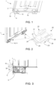
- Figures 1-3 show embodiments of an elevator door arrangement.
- the arrangement comprises an elevator door panel 1 and a door sill 30.
- the door panel 1 is movable along the door sill 30.
- the door panel 1 comprises at least one panel slider bracket 10.
- the at least one slider bracket 10 is movable in a groove 31 of the door sill 30.
- the arrangement comprises at least one panel slider 20 slidable in the groove 31 of the door sill 30 and mountable to said at least one slider bracket 10.
- the slider bracket 10 is irremovable and assembled to the door panel 1 during panel manufacturing. This will remove risks of poor installation of the door or human mistakes.
- the slider bracket 10, installed in the groove 31 of the sill 30, is configured to generate a panel-sill hook.
- the slider bracket 10 has a lower part 11, which is configured in such a way that when it is installed inside the sill 30 though the groove 31, the lower part 11 is positioned below the sill structure 32, thus forming a vertical gap C between the lower part 11 and the sill structure 32.
- the slider bracket 10 comprises a lateral protruding lower part 11 which in the assembled state of the elevator door arrangement extends below a sill structure 32 inside the sill 30.
- the slider bracket 10 has a lower part 11 comprising a lateral protruding extension to be assembled below a sill 30 structure 32 inside the sill 30.
- the slider bracket 10 comprises a hook formed lower part 11.
- the lower part 11 of the slider bracket 10 comprises a horizontal bend for retaining the door panel 1 against upward movement.
- the lateral protruding lower part 11 such as the retaining bend is configured to catch on sill profile edges and hook the door when the door panel 1 lifts as effect of pendulum impacts.
- the slider bracket 10 is made of metal sheet.
- the panel slider bracket 10 is riveted with rivets 2 to the door panel 1.
- the slider bracket 10 comprises an aperture 12 configured to receive the panel slider 20.
- Figure 2 shows a view of the door panel 1 with the slider 20 to be assembled to the slider bracket 10.
- the slider 20 comprises a sliding part 21 slidable in the groove 31 of the sill 30.
- the sliding part 21 slides in the groove 31 when the door panel 1 is moved in the door opening and closing directions.
- the slider 20 comprises a fixing part 22 cooperating with the aperture 12 in the slider bracket 10 so that the slider 20 is kept in place in the aperture 12, in particular during operation of the arrangement, and the fixing part 22 prevents the slider 20 from becoming detached from its place.
- the fixing part 22 comprises securing means 23 providing secure fixing of the slider 20 in the slider bracket 10.
- the securing means 23 comprises a fixing means 25 such as a flexible, tensionable or spring loaded claw 25 or cantilever configured to lock the slider 20 in the aperture 12 of the slider bracket 10.
- the securing means 23 comprises a positioning means 26 such as a positioning protrusion 26 cooperating with the shape of the aperture 12 and configured to prevent installing the slider 20 in wrong position in the aperture 12 of the slider bracket 10.
- a poka-yoke or "mistake-proofing" feature has been added on flexible retaining cantilevers or claws 25, thick areas 26 which will get in interference with the slider bracket 10 aperture 12 when the slider 20 will be inserted with opposite orientation.
- a certain gap is needed between the lateral protruding lower part 11 such as the retaining bend 11 in slider brackets 10 and matching edges 32 in sill 30 profile, allowing fitters to lift the door panel 1 above bends in a top lintel 4 and engage horizontal fire labyrinths 3 present at the top of the panel 1 to them.
- Figure 3 shows a vertical clearance C between the slider bracket 10 and the door sill 30 while a door panel top 3 is engaged with a top lintel 4, see also Figure 6 .
- the panel slider 20 once installed in the aperture 12 of the bracket 10 which is installed in the groove 31 will further increase the effectiveness of the panel-sill hook by limiting the vertical clearance C that is needed during installation.
- Such vertical clearance C or vertical gap C if not limited, will allow vertical lifting of the door panel 1 during impacts (e.g. perpendicular to door opening direction) which could lead to door panel labyrinth 3 horizontal disengagement from door frame upper part 4 or lintel upper part 4, thus compromising functioning of the door.
- the slider 20 is configured to limit the vertical clearance C between the lower part 11 of the slider bracket 10 and the sill 30.
- the slider 20 comprises an articulated appendix 24 such as a flange 24 configured to limit the vertical clearance C between the lower part 11 of the slider bracket 10 and the sill 30.
- an articulated appendix 24 such as a flange 24 configured to limit the vertical clearance C between the lower part 11 of the slider bracket 10 and the sill 30.
- the articulated appendix 24 is pivoted at an area or point 27 below the sliding part 21.
- the area or point 27 comprises a joint or pivot.
- the area or point 27 comprises material with reduced material thickness and/or flexible material.
- the slider 20 comprises an articulated appendix 24 acting as an integrated deformable shim 24.
- the articulated appendix 24 comprises a nose part 28 configured to follow the shape of the lower part 11.
- the nose part 28 comprises a rounded or chamfered shape to facilitate following the shape of the lower part 11.
- Figure 4 shows the slider 20 with the articulated appendix 24 that bends following to the shape of the slider bracket 10 during installation when the door panel 1 is guided in the elevator door arrangement.
- the slider 20 is inserted vertically through the aperture 12, the sliding part 21 moving into the groove 31.
- the slider 20 is further moved downwards so that the articulated appendix 24 is pivoted, preferably at area 27, in the vertical gap C following the shape of the lower part 11 of the slider bracket 10.
- the securing means 23 of the fixing part 22, in particular the positioning means 26, prevent the slider 20 from becoming assembled wrongly in the aperture 12.
- a location of preventing is denoted with arrow 26/12.
- the slider 20 with the articulated appendix 24 located in the vertical gap C provides for reduced vertical movement of the door panel 1.
- the securing means 23 of the fixing part 22, in particular the fixing means 25 prevent the slider 20 from becoming detached from its place in the aperture 12.
- Figures 7 and 8 show a securing means 23 of the fixing part, in particular the positioning means 26, preventing the slider 20 from becoming assembled wrongly in an aperture 12 of the slider bracket 10.
- the articulated appendix 24 is configured to bend according to the shape of the slider bracket 10 lower end during installation.
- the articulated appendix 24 is provided at a lower end of the sliding part 21.
- the articulated appendix 24 will act as a shim while being positioned in the vertical gap C between the lower part 11 of the bracket 10 and the sill 30.
- articulated appendix 24 is pivotable according to the shape of the lower part 11 of the slider bracket 10.
- the articulated appendix 24 is pivotable to a position perpendicular to a vertical assembly and disassembly movement direction of the slider 20.
- the slider 20 while assembled to the bracket 10 and the articulated appendix 24 being pivoted in the vertical gap C is configured to reduce the vertical gap C between the slider bracket 10 and the door sill 30.
- the articulated appendix 24 in the vertical gap will reduce the allowed vertical movement of the door panel 1 shown Figure 5 and prevent the door panel 1 top labyrinth 3 shown in Figure 6 from disengaging from the lintel 4 during impact test and use of the elevator door arrangement.
- Figure 9 shows different views of the slider 20.
Landscapes
- Elevator Door Apparatuses (AREA)
Abstract
Description
- The invention relates to an elevator door arrangement and a method for guiding an elevator door, in particular preventing elevator door panel derailment.
- In connection with an elevator door, the interface between door sill and panels shall have features retaining a door panel in position should a guiding element fixed to the door panel such as a panel slider fail, as requested by EN81-20. Such devices shall prevent panel derailment from a sill groove when panels will be subject to impacts perpendicular to door opening direction.
- Furthermore, in case of vandal proof doors such interface must contribute to guaranteeing proper functioning of the door even after aforementioned impacts, as requested by EN81-71.
- Retaining features, commonly implemented in industry as components hooking panel to door sill still, must not prevent movements needed during installation, as engagement of panel fire labyrinths on door frame.
- In prior art, EN81-20 compliant retaining features are typically integrated in slider brackets or other devices meant to be assembled on site, as finalization of door panel installation sequence, after movements to hung panel to hangers and to engage panel fire labyrinths (if present) on door frame will be performed. This can expose the design to code compliancy issues and safety risks for passengers in case fasteners securing panel-sill interface components will fail due to poor installation or human mistakes. Sensibility to human mistake is particularly true in case retaining features are integrated in slider bracket designed to be periodically disassembled and inspected during maintenance visits.
- An object of the present invention is to present an improved elevator door arrangement and a method for guiding an elevator door in an elevator door arrangement. An object of the present invention is a design where features preventing panel derailment as required by EN81-20 are part of panel slider bracket, which is irremovable and assembled during panel manufacturing. This will improve safety of the elevator door and remove risks mentioned above.
- According to an embodiment the panel slider bracket is designed to trip and engage on a sill profile when doors are impacted, but still guarantees enough clearances with sill profile allowing door panel installation.
- It is brought forward a new elevator door arrangement comprising an elevator door panel and a door sill, the door panel being movable along the door sill;
- the door panel comprises at the bottom at least one panel slider bracket being movable in a groove of the door sill; and
- the arrangement comprises at least one panel slider mountable to said at least one slider bracket and slidable in the groove; wherein
- the slider bracket comprises a lateral protruding lower part which is configured inside the sill to extend below a sill structure.
- According to an embodiment, the slider bracket is assembled to the door panel during panel manufacturing.
- According to an embodiment, the slider bracket is irremovable in the assembled state of the elevator door arrangement.
- According to an embodiment, the panel slider bracket is riveted with rivets to the door panel.
- According to an embodiment, the slider bracket, when installed in the groove of the sill, is configured to generate a panel-sill hook.
- According to an embodiment, the slider bracket comprises a hook formed lower part.
- According to an embodiment, the slider bracket is made of metal sheet.
- According to an embodiment, the slider bracket has a lower part, which is configured in such a way that when it is installed inside the sill though the groove, the lower part is positioned below the sill structure, thus forming a vertical gap between the lower part and the sill structure.
- According to an embodiment, the slider bracket has a lower part comprising a lateral protruding extension to be assembled below a sill structure inside the sill.
- According to an embodiment, the lower part of the slider bracket comprises a horizontal bend for retaining the door panel against upward movement.
- According to an embodiment, the lateral protruding lower part such as the retaining bend is configured to catch on a sill profile edge and hook the door when the door panel lifts as effect of pendulum impacts.
- According to an embodiment, the panel slider is configured to limit the vertical clearance between the lower part and the sill.
- According to an embodiment, the panel slider comprises an articulated appendix configured to limit the vertical clearance between the lower part and the sill.
- According to an embodiment, the articulated appendix is configured to bend following the shape of the slider bracket lower end during installation.
- According to an embodiment, the articulated appendix is pivotable according to the shape of the lower part of the slider bracket.
- According to an embodiment, the articulated appendix is provided at a lower end of the sliding part.
- According to an embodiment the articulated appendix is pivoted at an area or point below the sliding part. According to an embodiment said area or point comprises a joint or pivot. According to an embodiment said area or point comprises material with reduced material thickness and/or flexible material.
- According to an embodiment the articulated appendix is pivotable to a position perpendicular to a vertical assembly and disassembly movement direction of the slider.
- According to an embodiment the slider comprises an articulated appendix acting as an integrated deformable shim. According to an embodiment the articulated appendix will act as a shim while being positioned in the vertical gap between the lower part of the bracket and the sill.
- According to an embodiment the articulated appendix comprises a nose part configured to follow the shape of the lower part. According to an embodiment the nose part comprises a rounded or chamfered shape to facilitate following the shape of the lower part.
- According to an embodiment, while the panel slider has been assembled to the bracket and the articulated appendix has been pivoted in the vertical gap between the slider bracket and the door sill, the panel slider is configured to reduce the vertical gap.
- According to an embodiment, the slider bracket comprises an aperture configured to receive the panel slider.
- According to an embodiment, the panel slider comprises a sliding part slidable in the groove of the sill.
- According to an embodiment, the panel slider comprises a fixing part cooperating with the aperture.
- According to an embodiment, the fixing part comprises securing means providing secure fixing of the panel slider to the slider bracket.
- According to an embodiment, the securing means comprises a fixing means configured to lock the panel slider to the aperture. According to an embodiment, the fixing means comprises a flexible, tensionable or spring loaded claw or cantilever.
- According to an embodiment, the securing means comprises a positioning means, such as a positioning protrusion, cooperating with the shape of the aperture and configured to prevent installing the panel slider in wrong position in the aperture.
- It is also brought forward a new method for guiding an elevator door in an elevator door arrangement as described above and hereinafter, comprising:
- assembling at least one panel slider bracket as described above and hereinafter to an elevator door panel, and
- mounting at least one panel slider as described above and hereinafter to said at least one slider bracket.
- The invention eliminates risks of non-compliancy with EN81-20 requirements caused by human mistakes happening during door installation or maintenance. Door safety is guaranteed independently by the presence of panel slider, a wearable component subject to replacement which is meant to be installed on site as last operation in door panel installation sequence and periodically removable for inspection.
- Compliancy with EN81-71 requirements can be achieved thanks to a panel slider that once installed will further increase effectiveness of panel-sill hooking, limiting vertical clearance needed during installation. Such clearance if not limited will allow vertical lifting of door panel during impacts perpendicular to door opening direction which could lead to horizontal door panel labyrinth disengagement from door frame, compromising functioning of the door.
- Special design of the preferably plastic slider allows compliancy to EN81-71 requirement, without hindering door installability.
- The invention will in the following be described in greater detail by means of preferred embodiments with reference to the attached drawings, in which:
-
Figure 1 shows a view of an elevator door panel with panel slider brackets, -
Figure 2 shows another view of the elevator door panel with a slider to be assembled to a slider bracket, -
Figure 3 shows a vertical gap between the slider bracket and a door sill while door panel top parts are engaged with a top lintel, -
Figure 4 shows the slider with an articulated appendix that bends following the shape of the slider bracket during installation, -
Figure 5 shows the articulated appendix acting as a shim between the slider bracket and a door sill, -
Figure 6 shows a door panel top part engaged with a top lintel, -
Figures 7 and 8 show a securing means of the fixing part, in particular the positioning means, preventing the slider from becoming assembled wrongly in an aperture of the slider bracket, and -
Figure 9 shows different views of the slider. -
Figures 1-3 show embodiments of an elevator door arrangement. The arrangement comprises anelevator door panel 1 and adoor sill 30. Thedoor panel 1 is movable along thedoor sill 30. Further, thedoor panel 1 comprises at least onepanel slider bracket 10. The at least oneslider bracket 10 is movable in agroove 31 of thedoor sill 30. The arrangement comprises at least onepanel slider 20 slidable in thegroove 31 of thedoor sill 30 and mountable to said at least oneslider bracket 10. - Features preventing
door panel 1 derailment as required by EN81-20 are part of thepanel slider bracket 10 attached in the Figures to thedoor panel 1 bottom. - According to an embodiment the
slider bracket 10 is irremovable and assembled to thedoor panel 1 during panel manufacturing. This will remove risks of poor installation of the door or human mistakes. - According to an embodiment the
slider bracket 10, installed in thegroove 31 of thesill 30, is configured to generate a panel-sill hook. - According to an embodiment the
slider bracket 10 has alower part 11, which is configured in such a way that when it is installed inside thesill 30 though thegroove 31, thelower part 11 is positioned below thesill structure 32, thus forming a vertical gap C between thelower part 11 and thesill structure 32. - The
slider bracket 10 comprises a lateral protrudinglower part 11 which in the assembled state of the elevator door arrangement extends below asill structure 32 inside thesill 30. - According to an embodiment the
slider bracket 10 has alower part 11 comprising a lateral protruding extension to be assembled below asill 30structure 32 inside thesill 30. - According to an embodiment the
slider bracket 10 comprises a hook formedlower part 11. - According to an embodiment the
lower part 11 of theslider bracket 10 comprises a horizontal bend for retaining thedoor panel 1 against upward movement. - The lateral protruding
lower part 11 such as the retaining bend is configured to catch on sill profile edges and hook the door when thedoor panel 1 lifts as effect of pendulum impacts. - According to an embodiment the
slider bracket 10 is made of metal sheet. - According to an embodiment the
panel slider bracket 10 is riveted withrivets 2 to thedoor panel 1. - When the at least one
slider bracket 10 is riveted in the manufacturing line, the possibility of getting loose/ineffective thereof during the elevator life as could happen in case of screwed connection will be reduced. This will also prevent loss of EN81-20 compliancy in case fitter or maintenance mechanics won't correctly install this component. Installation and inspection of wearable parts e.g.panel sliders 20 doesn't requireslider bracket 10 disassembling. - Compliancy with EN81-71 requirements is achieved with the
panel slider 20 slidable in thedoor sill 30groove 31. - According to an embodiment the
slider bracket 10 comprises anaperture 12 configured to receive thepanel slider 20. -
Figure 2 shows a view of thedoor panel 1 with theslider 20 to be assembled to theslider bracket 10. Theslider 20 comprises a slidingpart 21 slidable in thegroove 31 of thesill 30. The slidingpart 21 slides in thegroove 31 when thedoor panel 1 is moved in the door opening and closing directions. - According to an embodiment the
slider 20 comprises a fixingpart 22 cooperating with theaperture 12 in theslider bracket 10 so that theslider 20 is kept in place in theaperture 12, in particular during operation of the arrangement, and the fixingpart 22 prevents theslider 20 from becoming detached from its place. - According to an embodiment the fixing
part 22 comprises securing means 23 providing secure fixing of theslider 20 in theslider bracket 10. - According to an embodiment the securing means 23 comprises a fixing means 25 such as a flexible, tensionable or spring loaded
claw 25 or cantilever configured to lock theslider 20 in theaperture 12 of theslider bracket 10. - According to an embodiment the securing means 23 comprises a positioning means 26 such as a
positioning protrusion 26 cooperating with the shape of theaperture 12 and configured to prevent installing theslider 20 in wrong position in theaperture 12 of theslider bracket 10. To prevent mistakes inpanel slider 20 installation orientation, a poka-yoke or "mistake-proofing" feature has been added on flexible retaining cantilevers orclaws 25,thick areas 26 which will get in interference with theslider bracket 10aperture 12 when theslider 20 will be inserted with opposite orientation. Thus, by the shape of the slider the possibility of inserting the slider in the wrong direction is avoided. - A certain gap is needed between the lateral protruding
lower part 11 such as the retainingbend 11 inslider brackets 10 and matchingedges 32 insill 30 profile, allowing fitters to lift thedoor panel 1 above bends in atop lintel 4 and engagehorizontal fire labyrinths 3 present at the top of thepanel 1 to them. -
Figure 3 shows a vertical clearance C between theslider bracket 10 and thedoor sill 30 while adoor panel top 3 is engaged with atop lintel 4, see alsoFigure 6 . - The
panel slider 20 once installed in theaperture 12 of thebracket 10 which is installed in thegroove 31 will further increase the effectiveness of the panel-sill hook by limiting the vertical clearance C that is needed during installation. Such vertical clearance C or vertical gap C, if not limited, will allow vertical lifting of thedoor panel 1 during impacts (e.g. perpendicular to door opening direction) which could lead todoor panel labyrinth 3 horizontal disengagement from door frameupper part 4 or lintelupper part 4, thus compromising functioning of the door. - The
slider 20 is configured to limit the vertical clearance C between thelower part 11 of theslider bracket 10 and thesill 30. - According to an embodiment the
slider 20 comprises an articulatedappendix 24 such as aflange 24 configured to limit the vertical clearance C between thelower part 11 of theslider bracket 10 and thesill 30. - According to an embodiment the articulated
appendix 24 is pivoted at an area orpoint 27 below the slidingpart 21. According to an embodiment the area orpoint 27 comprises a joint or pivot. According to an embodiment the area orpoint 27 comprises material with reduced material thickness and/or flexible material. - According to an embodiment the
slider 20 comprises an articulatedappendix 24 acting as an integrateddeformable shim 24. - According to an embodiment the articulated
appendix 24 comprises anose part 28 configured to follow the shape of thelower part 11. According to an embodiment thenose part 28 comprises a rounded or chamfered shape to facilitate following the shape of thelower part 11. -
Figure 4 shows theslider 20 with the articulatedappendix 24 that bends following to the shape of theslider bracket 10 during installation when thedoor panel 1 is guided in the elevator door arrangement. - According to a first example step the
slider 20 is inserted vertically through theaperture 12, the slidingpart 21 moving into thegroove 31. - According to a second example step the
slider 20 is further moved downwards so that the articulatedappendix 24 is pivoted, preferably atarea 27, in the vertical gap C following the shape of thelower part 11 of theslider bracket 10. The securing means 23 of the fixingpart 22, in particular the positioning means 26, prevent theslider 20 from becoming assembled wrongly in theaperture 12. A location of preventing is denoted witharrow 26/12. - According to a third example step the
slider 20 with the articulatedappendix 24 located in the vertical gap C provides for reduced vertical movement of thedoor panel 1. The securing means 23 of the fixingpart 22, in particular the fixing means 25 prevent theslider 20 from becoming detached from its place in theaperture 12. -
Figures 7 and 8 show a securing means 23 of the fixing part, in particular the positioning means 26, preventing theslider 20 from becoming assembled wrongly in anaperture 12 of theslider bracket 10. - According to an embodiment the articulated
appendix 24 is configured to bend according to the shape of theslider bracket 10 lower end during installation. - According to an embodiment the articulated
appendix 24 is provided at a lower end of the slidingpart 21. - According to an embodiment the articulated
appendix 24 will act as a shim while being positioned in the vertical gap C between thelower part 11 of thebracket 10 and thesill 30. - According to an embodiment the articulated
appendix 24 is pivotable according to the shape of thelower part 11 of theslider bracket 10. - According to an embodiment the articulated
appendix 24 is pivotable to a position perpendicular to a vertical assembly and disassembly movement direction of theslider 20. - According to an embodiment the
slider 20 while assembled to thebracket 10 and the articulatedappendix 24 being pivoted in the vertical gap C is configured to reduce the vertical gap C between theslider bracket 10 and thedoor sill 30. - The articulated
appendix 24 in the vertical gap will reduce the allowed vertical movement of thedoor panel 1 shownFigure 5 and prevent thedoor panel 1top labyrinth 3 shown inFigure 6 from disengaging from thelintel 4 during impact test and use of the elevator door arrangement. -
Figure 9 shows different views of theslider 20. - It will be obvious to a person skilled in the art that, as the technology advances, the inventive concept can be implemented in various ways. The invention and its embodiments are not limited to the examples described above but may vary within the scope of the claims.
Claims (15)
- An elevator door arrangement comprises an elevator door panel (1) and a door sill (30), the door panel (1) being movable along the door sill (30);the door panel (1) comprises at the bottom at least one panel slider bracket (10) being movable in a groove (31) of the door sill (30); andthe arrangement comprises at least one panel slider (20) mountable to said at least one slider bracket (10) and slidable in the groove (31); whereinthe slider bracket (10) comprises a lateral protruding lower part (11) which is configured inside the sill (30) to extend below a sill structure (32).
- The arrangement according to claim 1, wherein the slider bracket (10) is assembled to the door panel (1) during panel manufacturing.
- The arrangement according to claim 1 or 2, wherein the slider bracket (10), when installed in the groove (31) of the sill (30), is configured to generate a panel-sill hook.
- The arrangement according to any of claims 1 to 3, wherein the slider bracket (10) has a lower part (11), which is configured in such a way that when it is installed inside the sill (30) though the groove (31), the lower part is positioned below the sill structure, thus forming a vertical gap (C) between the lower part and the sill structure.
- The arrangement according to any of claims 1 to 4, wherein the slider bracket (10) has a lower part (11) comprising a lateral protruding extension to be assembled below a sill (30) structure (32) inside the sill (30).
- The arrangement according to any of claims 1 to 5, wherein the lower part (11) of the slider bracket (10) comprises a horizontal bend for retaining the door panel (1) against upward movement.
- The arrangement according to claim 6, wherein the lateral protruding lower part (11) such as the retaining bend is configured to catch on a sill profile edge (32) and hook the door when the door panel (1) lifts as effect of pendulum impacts.
- The arrangement according to any of claims 1 to 7, wherein the panel slider (20) is configured to limit the vertical clearance (C) between the lower part (11) and the sill (30).
- The arrangement according to any of claims 1 to 8, wherein the panel slider (20) comprises an articulated appendix (24) configured to limit the vertical clearance (C) between the lower part (11) and the sill (30).
- The arrangement according to claim 9, wherein the articulated appendix (24) is configured to bend following the shape of the slider bracket (10) lower end during installation, or the articulated appendix (24) is pivotable according to the shape of the lower part (11) of the slider bracket (10).
- The arrangement according to claim 9 or 10, wherein while the panel slider (20) has been assembled to the bracket (10) and the articulated appendix (24) has been pivoted in the vertical gap (C) between the slider bracket (10) and the door sill (30), the panel slider is configured to reduce the vertical gap.
- The arrangement according to any of claims 1 to 11, wherein the slider bracket (10) comprises an aperture (12) configured to receive the panel slider (20) and the panel slider comprises a sliding part (21) slidable in the groove (31) of the sill (30).
- The arrangement according to claim 12, wherein the panel slider (20) comprises a fixing part (22) cooperating with the aperture (12).
- The arrangement according to claim 13, wherein the fixing part (22) comprises securing means (23) providing secure fixing of the panel slider (20) to the slider bracket (10), whereinpreferably the securing means comprises a fixing means (25) configured to lock the panel slider to the aperture (12), and whereinpreferably the securing means comprises a positioning means (26), such as a positioning protrusion, cooperating with the shape of the aperture (12) and configured to prevent installing the panel slider in wrong position in the aperture (12).
- A method for guiding an elevator door in an elevator door arrangement according to any of claims 1 to 14 comprisingassembling at least one panel slider bracket (10) according to any of previous claims to an elevator door panel (1), andmounting at least one panel slider (20) according to any of previous claims to said at least one slider bracket (10).
Priority Applications (3)
| Application Number | Priority Date | Filing Date | Title |
|---|---|---|---|
| EP23173665.3A EP4464639A1 (en) | 2023-05-16 | 2023-05-16 | Elevator door arrangement and method |
| US18/627,728 US20240383726A1 (en) | 2023-05-16 | 2024-04-05 | Elevator door arrangement and method |
| CN202410585598.9A CN118992768A (en) | 2023-05-16 | 2024-05-13 | Elevator door apparatus and method |
Applications Claiming Priority (1)
| Application Number | Priority Date | Filing Date | Title |
|---|---|---|---|
| EP23173665.3A EP4464639A1 (en) | 2023-05-16 | 2023-05-16 | Elevator door arrangement and method |
Publications (1)
| Publication Number | Publication Date |
|---|---|
| EP4464639A1 true EP4464639A1 (en) | 2024-11-20 |
Family
ID=86386930
Family Applications (1)
| Application Number | Title | Priority Date | Filing Date |
|---|---|---|---|
| EP23173665.3A Pending EP4464639A1 (en) | 2023-05-16 | 2023-05-16 | Elevator door arrangement and method |
Country Status (3)
| Country | Link |
|---|---|
| US (1) | US20240383726A1 (en) |
| EP (1) | EP4464639A1 (en) |
| CN (1) | CN118992768A (en) |
Citations (5)
| Publication number | Priority date | Publication date | Assignee | Title |
|---|---|---|---|---|
| EP0559988A1 (en) * | 1991-12-20 | 1993-09-15 | Otis Elevator Company | Device for attaching a guide shoe to the lower part of a sliding elevator door |
| KR20080082879A (en) * | 2007-03-09 | 2008-09-12 | (주)진흥엔지니어링 | Door guide device for elevator |
| CN101850926A (en) * | 2009-04-06 | 2010-10-06 | 三菱电机株式会社 | elevator door device |
| CN105947855A (en) * | 2016-06-21 | 2016-09-21 | 浙江屹立电梯有限公司 | Disconnection-preventing sill structure |
| CN115028047A (en) * | 2022-06-02 | 2022-09-09 | 广州广日电气设备有限公司 | Lower threshold structure of elevator |
Family Cites Families (11)
| Publication number | Priority date | Publication date | Assignee | Title |
|---|---|---|---|---|
| US3426480A (en) * | 1967-07-07 | 1969-02-11 | Westinghouse Electric Corp | Door assembly |
| US4781270A (en) * | 1987-03-02 | 1988-11-01 | Delaware Capital Formation, Inc. | Elevator door arrangement |
| FI98363C (en) * | 1994-10-21 | 1997-06-10 | Kone Oy | Threshold system for elevator basket |
| JP6229943B2 (en) * | 2014-03-05 | 2017-11-15 | フジテック株式会社 | Elevator door opening and closing device |
| KR20150117928A (en) * | 2014-04-11 | 2015-10-21 | 삼흥산업주식회사 | Device for preventing door from derailing in elevator |
| KR101413959B1 (en) * | 2014-05-02 | 2014-07-07 | 세화정공 주식회사 | Guide shoe for door of elevator |
| CN205099176U (en) * | 2015-11-02 | 2016-03-23 | 吴江金狮电梯科技有限公司 | Elevator anticreep sill elevator entrance system |
| CN107651543B (en) * | 2016-07-25 | 2019-06-04 | 上海三菱电梯有限公司 | Roll type elevator door sliding block |
| CN106829706A (en) * | 2017-04-10 | 2017-06-13 | 江南嘉捷电梯股份有限公司 | A kind of elevator cage component with anti-drop function |
| KR102188000B1 (en) * | 2020-01-31 | 2020-12-07 | (주)금호엘리베이터 | Elevator platform door departure prevention device |
| US11459211B2 (en) * | 2020-06-25 | 2022-10-04 | Otis Elevator Company | Narrow groove elevator doorsill |
-
2023
- 2023-05-16 EP EP23173665.3A patent/EP4464639A1/en active Pending
-
2024
- 2024-04-05 US US18/627,728 patent/US20240383726A1/en active Pending
- 2024-05-13 CN CN202410585598.9A patent/CN118992768A/en active Pending
Patent Citations (5)
| Publication number | Priority date | Publication date | Assignee | Title |
|---|---|---|---|---|
| EP0559988A1 (en) * | 1991-12-20 | 1993-09-15 | Otis Elevator Company | Device for attaching a guide shoe to the lower part of a sliding elevator door |
| KR20080082879A (en) * | 2007-03-09 | 2008-09-12 | (주)진흥엔지니어링 | Door guide device for elevator |
| CN101850926A (en) * | 2009-04-06 | 2010-10-06 | 三菱电机株式会社 | elevator door device |
| CN105947855A (en) * | 2016-06-21 | 2016-09-21 | 浙江屹立电梯有限公司 | Disconnection-preventing sill structure |
| CN115028047A (en) * | 2022-06-02 | 2022-09-09 | 广州广日电气设备有限公司 | Lower threshold structure of elevator |
Also Published As
| Publication number | Publication date |
|---|---|
| CN118992768A (en) | 2024-11-22 |
| US20240383726A1 (en) | 2024-11-21 |
Similar Documents
| Publication | Publication Date | Title |
|---|---|---|
| CN102471027B (en) | Method and arrangement for opening and closing a suspended ceiling or corresponding of an elevator car and also a locking device | |
| CN102159487B (en) | Structure for preventing deviation of elevator doors and insertion of foreign objects | |
| JP2016176331A (en) | Sliding door closer set | |
| EP2674382A1 (en) | Anti-derailment device for lift or elevator door leaves | |
| US20240383726A1 (en) | Elevator door arrangement and method | |
| EP3591155A1 (en) | Sliding door system with sliding door and wall module | |
| US6189658B1 (en) | Procedure for moving the landing door of an elevator, and a door coupler | |
| CN110114297A (en) | For connecting the attachment device and method of the wall elements in lift car | |
| HK40119063A (en) | Elevator door arrangement and method | |
| US10767394B2 (en) | Lockable coupling device | |
| EP1496005A1 (en) | Landing stage door of elevator | |
| EP1346942A1 (en) | Car upper handrail device of elevator | |
| CN113173478A (en) | Elevator car with camera mount | |
| JP5144105B2 (en) | Sliding door device | |
| JP2017160729A (en) | Joinery | |
| JP7782638B1 (en) | Elevator car control panel and elevator car control panel installation method | |
| JPH0742066B2 (en) | Elevator doors | |
| EP3929135B1 (en) | Narrow groove elevator doorsill | |
| JP4279512B2 (en) | Structure of shutter device for elevator | |
| CN112955399B (en) | Side door device of elevator hall | |
| JP6785518B2 (en) | How to install elevator door stoppers and elevator door stoppers | |
| JP4256746B2 (en) | Elevator doorway installation method | |
| CN214495350U (en) | Anti-drop's room door structure | |
| CN110461754B (en) | Entrance and exit device for elevator | |
| KR102891452B1 (en) | Detachable guide rail for window sash for easy window installation |
Legal Events
| Date | Code | Title | Description |
|---|---|---|---|
| PUAI | Public reference made under article 153(3) epc to a published international application that has entered the european phase |
Free format text: ORIGINAL CODE: 0009012 |
|
| STAA | Information on the status of an ep patent application or granted ep patent |
Free format text: STATUS: THE APPLICATION HAS BEEN PUBLISHED |
|
| AK | Designated contracting states |
Kind code of ref document: A1 Designated state(s): AL AT BE BG CH CY CZ DE DK EE ES FI FR GB GR HR HU IE IS IT LI LT LU LV MC ME MK MT NL NO PL PT RO RS SE SI SK SM TR |
|
| STAA | Information on the status of an ep patent application or granted ep patent |
Free format text: STATUS: REQUEST FOR EXAMINATION WAS MADE |
|
| 17P | Request for examination filed |
Effective date: 20241129 |
|
| RBV | Designated contracting states (corrected) |
Designated state(s): AL AT BE BG CH CY CZ DE DK EE ES FI FR GB GR HR HU IE IS IT LI LT LU LV MC ME MK MT NL NO PL PT RO RS SE SI SK SM TR |
|
| P01 | Opt-out of the competence of the unified patent court (upc) registered |
Free format text: CASE NUMBER: APP_875/2025 Effective date: 20250108 |
|
| GRAP | Despatch of communication of intention to grant a patent |
Free format text: ORIGINAL CODE: EPIDOSNIGR1 |
|
| STAA | Information on the status of an ep patent application or granted ep patent |
Free format text: STATUS: GRANT OF PATENT IS INTENDED |
|
| INTG | Intention to grant announced |
Effective date: 20260121 |