EP4464608A1 - A packaging apparatus for forming a plurality of sealed packages filled with a pourable product - Google Patents
A packaging apparatus for forming a plurality of sealed packages filled with a pourable product Download PDFInfo
- Publication number
- EP4464608A1 EP4464608A1 EP24169372.0A EP24169372A EP4464608A1 EP 4464608 A1 EP4464608 A1 EP 4464608A1 EP 24169372 A EP24169372 A EP 24169372A EP 4464608 A1 EP4464608 A1 EP 4464608A1
- Authority
- EP
- European Patent Office
- Prior art keywords
- tube
- speed
- advancement
- space
- gas pressure
- Prior art date
- Legal status (The legal status is an assumption and is not a legal conclusion. Google has not performed a legal analysis and makes no representation as to the accuracy of the status listed.)
- Pending
Links
Images

Classifications
-
- B—PERFORMING OPERATIONS; TRANSPORTING
- B65—CONVEYING; PACKING; STORING; HANDLING THIN OR FILAMENTARY MATERIAL
- B65B—MACHINES, APPARATUS OR DEVICES FOR, OR METHODS OF, PACKAGING ARTICLES OR MATERIALS; UNPACKING
- B65B9/00—Enclosing successive articles, or quantities of material, e.g. liquids or semiliquids, in flat, folded, or tubular webs of flexible sheet material; Subdividing filled flexible tubes to form packages
- B65B9/10—Enclosing successive articles, or quantities of material, in preformed tubular webs, or in webs formed into tubes around filling nozzles, e.g. extruded tubular webs
- B65B9/12—Subdividing filled tubes to form two or more packages by sealing or securing involving displacement of contents
-
- B—PERFORMING OPERATIONS; TRANSPORTING
- B65—CONVEYING; PACKING; STORING; HANDLING THIN OR FILAMENTARY MATERIAL
- B65B—MACHINES, APPARATUS OR DEVICES FOR, OR METHODS OF, PACKAGING ARTICLES OR MATERIALS; UNPACKING
- B65B31/00—Packaging articles or materials under special atmospheric or gaseous conditions; Adding propellants to aerosol containers
- B65B31/02—Filling, closing, or filling and closing, containers or wrappers in chambers maintained under vacuum or superatmospheric pressure or containing a special atmosphere, e.g. of inert gas
-
- B—PERFORMING OPERATIONS; TRANSPORTING
- B65—CONVEYING; PACKING; STORING; HANDLING THIN OR FILAMENTARY MATERIAL
- B65B—MACHINES, APPARATUS OR DEVICES FOR, OR METHODS OF, PACKAGING ARTICLES OR MATERIALS; UNPACKING
- B65B31/00—Packaging articles or materials under special atmospheric or gaseous conditions; Adding propellants to aerosol containers
- B65B31/04—Evacuating, pressurising or gasifying filled containers or wrappers by means of nozzles through which air or other gas, e.g. an inert gas, is withdrawn or supplied
- B65B31/044—Evacuating, pressurising or gasifying filled containers or wrappers by means of nozzles through which air or other gas, e.g. an inert gas, is withdrawn or supplied the nozzles being combined with a filling device
- B65B31/045—Evacuating, pressurising or gasifying filled containers or wrappers by means of nozzles through which air or other gas, e.g. an inert gas, is withdrawn or supplied the nozzles being combined with a filling device of Vertical Form-Fill-Seal [VFFS] machines
-
- B—PERFORMING OPERATIONS; TRANSPORTING
- B65—CONVEYING; PACKING; STORING; HANDLING THIN OR FILAMENTARY MATERIAL
- B65B—MACHINES, APPARATUS OR DEVICES FOR, OR METHODS OF, PACKAGING ARTICLES OR MATERIALS; UNPACKING
- B65B51/00—Devices for, or methods of, sealing or securing package folds or closures; Devices for gathering or twisting wrappers, or necks of bags
- B65B51/10—Applying or generating heat or pressure or combinations thereof
- B65B51/26—Devices specially adapted for producing transverse or longitudinal seams in webs or tubes
-
- B—PERFORMING OPERATIONS; TRANSPORTING
- B65—CONVEYING; PACKING; STORING; HANDLING THIN OR FILAMENTARY MATERIAL
- B65B—MACHINES, APPARATUS OR DEVICES FOR, OR METHODS OF, PACKAGING ARTICLES OR MATERIALS; UNPACKING
- B65B55/00—Preserving, protecting or purifying packages or package contents in association with packaging
- B65B55/02—Sterilising, e.g. of complete packages
- B65B55/04—Sterilising wrappers or receptacles prior to, or during, packaging
- B65B55/08—Sterilising wrappers or receptacles prior to, or during, packaging by irradiation
-
- B—PERFORMING OPERATIONS; TRANSPORTING
- B65—CONVEYING; PACKING; STORING; HANDLING THIN OR FILAMENTARY MATERIAL
- B65B—MACHINES, APPARATUS OR DEVICES FOR, OR METHODS OF, PACKAGING ARTICLES OR MATERIALS; UNPACKING
- B65B57/00—Automatic control, checking, warning, or safety devices
- B65B57/02—Automatic control, checking, warning, or safety devices responsive to absence, presence, abnormal feed, or misplacement of binding or wrapping material, containers, or packages
- B65B57/04—Automatic control, checking, warning, or safety devices responsive to absence, presence, abnormal feed, or misplacement of binding or wrapping material, containers, or packages and operating to control, or to stop, the feed of such material, containers, or packages
-
- B—PERFORMING OPERATIONS; TRANSPORTING
- B65—CONVEYING; PACKING; STORING; HANDLING THIN OR FILAMENTARY MATERIAL
- B65B—MACHINES, APPARATUS OR DEVICES FOR, OR METHODS OF, PACKAGING ARTICLES OR MATERIALS; UNPACKING
- B65B9/00—Enclosing successive articles, or quantities of material, e.g. liquids or semiliquids, in flat, folded, or tubular webs of flexible sheet material; Subdividing filled flexible tubes to form packages
- B65B9/10—Enclosing successive articles, or quantities of material, in preformed tubular webs, or in webs formed into tubes around filling nozzles, e.g. extruded tubular webs
- B65B9/20—Enclosing successive articles, or quantities of material, in preformed tubular webs, or in webs formed into tubes around filling nozzles, e.g. extruded tubular webs the webs being formed into tubes in situ around the filling nozzles
- B65B9/2014—Tube advancing means
- B65B9/2028—Rollers or belts
-
- B—PERFORMING OPERATIONS; TRANSPORTING
- B65—CONVEYING; PACKING; STORING; HANDLING THIN OR FILAMENTARY MATERIAL
- B65B—MACHINES, APPARATUS OR DEVICES FOR, OR METHODS OF, PACKAGING ARTICLES OR MATERIALS; UNPACKING
- B65B9/00—Enclosing successive articles, or quantities of material, e.g. liquids or semiliquids, in flat, folded, or tubular webs of flexible sheet material; Subdividing filled flexible tubes to form packages
- B65B9/10—Enclosing successive articles, or quantities of material, in preformed tubular webs, or in webs formed into tubes around filling nozzles, e.g. extruded tubular webs
- B65B9/20—Enclosing successive articles, or quantities of material, in preformed tubular webs, or in webs formed into tubes around filling nozzles, e.g. extruded tubular webs the webs being formed into tubes in situ around the filling nozzles
- B65B9/2049—Package shaping devices acting on filled tubes prior to sealing the filling opening
-
- B—PERFORMING OPERATIONS; TRANSPORTING
- B65—CONVEYING; PACKING; STORING; HANDLING THIN OR FILAMENTARY MATERIAL
- B65B—MACHINES, APPARATUS OR DEVICES FOR, OR METHODS OF, PACKAGING ARTICLES OR MATERIALS; UNPACKING
- B65B9/00—Enclosing successive articles, or quantities of material, e.g. liquids or semiliquids, in flat, folded, or tubular webs of flexible sheet material; Subdividing filled flexible tubes to form packages
- B65B9/10—Enclosing successive articles, or quantities of material, in preformed tubular webs, or in webs formed into tubes around filling nozzles, e.g. extruded tubular webs
- B65B9/20—Enclosing successive articles, or quantities of material, in preformed tubular webs, or in webs formed into tubes around filling nozzles, e.g. extruded tubular webs the webs being formed into tubes in situ around the filling nozzles
- B65B9/207—Enclosing successive articles, or quantities of material, in preformed tubular webs, or in webs formed into tubes around filling nozzles, e.g. extruded tubular webs the webs being formed into tubes in situ around the filling nozzles the web advancing continuously
Definitions
- the present invention relates to a packaging machine for producing sealed packages of a pourable product, in particular a pourable food product.
- the present invention also relates to a method for producing sealed packages of a pourable product, in particular a pourable food product.
- liquid or pourable food products such as fruit juice, UHT (ultra-high-temperature treated) milk, wine, tomato sauce, etc.
- UHT ultra-high-temperature treated milk
- wine tomato sauce
- etc. are sold in packages made of sterilized packaging material.
- a typical example is the parallelepiped-shaped package for liquid or pourable food products known as Tetra Brik Aseptic (registered trademark), which is made by sealing and folding laminated strip packaging material.
- the packaging material has a multilayer structure comprising a base layer, e.g. of paper, covered on both sides with layers of heat-seal plastic material, e.g. polyethylene.
- the packaging material also comprises a layer of oxygen-barrier material (an oxygen-barrier layer), e.g. an aluminium foil, which is superimposed on a layer of heat-seal plastic material, and is in turn covered with another layer of heat-seal plastic material forming the inner face of the package eventually contacting the food product.
- Packages of this sort are normally produced on fully automatic packaging machines, which advance a web of packaging material through a sterilization apparatus for sterilizing the web of packaging material at a sterilization station and an isolation chamber (a closed and sterile environment) in which the sterilized web of packaging material is maintained and advanced.
- a sterilization apparatus for sterilizing the web of packaging material at a sterilization station
- an isolation chamber a closed and sterile environment
- the web of packaging material is folded and sealed longitudinally at a tube forming station to form a tube having a longitudinal seam portion, the tube being further fed along a vertical advancing direction.
- the tube is filled with a sterilized or sterile-processed pourable product, in particular a pourable food product, and is transversally sealed and subsequently cut along equally spaced transversal cross sections within a package forming unit of the packaging machine during advancement along the vertical advancing direction.
- a sterilized or sterile-processed pourable product in particular a pourable food product
- Pillow packages are so obtained within the packaging machine, each pillow package having a longitudinal sealing band, a top transversal sealing band and a bottom transversal sealing band.
- a typical packaging machine comprises a conveying device for advancing the web of packaging material along a web advancement path and a tube formed from the web of packaging material along a tube advancement path, the sterilization apparatus for sterilizing the web of packaging material prior to its formation into the tube, a tube forming and sealing device at least partially arranged within an isolation chamber and being configured to form the tube from the advancing web of packaging material and to longitudinally seal the tube, a filling device for filling the tube with the pourable product and a package forming unit adapted to form, transversally seal and cut the single packages from the tube of packaging material.
- a typical packaging machine also comprises a tensioning device configured to control the tension of the tube, i.e. of the packaging material forming the tube.
- a tensioning device configured to control the tension of the tube, i.e. of the packaging material forming the tube.
- Examples of a packaging machine comprising a tensioning device are disclosed in patent documents EP3725692B1 and EP3725689B1 in the name of the Applicant.
- the hydrostatic pressure provided by the pourable product within the tube is sufficiently high as otherwise irregularly shaped packages would be obtained.
- the pourable product column present in the tube for providing for the required hydrostatic pressure extends at least 500 mm upwards from the hit position (i.e. the position at which the respective forming, sealing and cutting assemblies start to contact the advancing tube).
- patent document EP3456638B1 in the name of the Applicant proposes to provide a pressurizing device configured to direct, in use, a flow of sterile gas into the tube for obtaining a gas pressure within the tube providing a correct forming pressure. In such a way, the required hydrostatic pressure provided by the product column is reduced.
- a need is felt to improve this machine.
- a need is felt to increase flexibility.
- Number 1 indicates as a whole a packaging machine for producing sealed packages 2 of a pourable food product, such as pasteurized milk or fruit juice, from a tube 3 of a web 4 of packaging material.
- tube 3 extends along a longitudinal axis, in particular having a vertical orientation.
- Web 4 of packaging material has a multilayer structure, and comprises a layer of fibrous material, normally paper, covered on both sides with respective layers of heat-seal plastic material, e.g. polyethylene.
- web 4 also comprises a layer of gas- and light-barrier material, e.g. aluminium foil or ethylene vinyl alcohol (EVOH) film, and at least a first and a second layer of heat-seal plastic material.
- gas- and light-barrier material e.g. aluminium foil or ethylene vinyl alcohol (EVOH) film
- EVOH ethylene vinyl alcohol
- the layer of gas- and light-barrier material is superimposed on the first layer of heat-seal plastic material, and is in turn covered with the second layer of heat-seal plastic material.
- the second layer of heat-seal plastic material forms the inner face of package 2 eventually contacting the food product.
- a typical package 2 obtained by packaging apparatus 1 comprises a sealed longitudinal seam portion and a pair of transversal seal portions 66, in particular a pair of top and bottom transversal seal portions 66 (i.e. one seal portion 66 at an upper portion of package 2 and another seal portion 66 at a lower portion of package 2).
- packaging machine 1 comprises a conveying device 5 for advancing in a known manner web 4 along a web advancement path P from a delivery station to a forming station 9, at which, in use, web 4 is formed into tube 3.
- Conveying device 5 is also configured to advancing tube 3 along a tube advancement path Q.
- Packaging machine 1 comprises an isolation chamber 10 having an inner environment 11, in particular an inner sterile environment 11, containing a sterile gas, in particular sterile air, and being separated from an outer environment 12.
- Packaging machine 1 comprises a tube forming device 13 extending along a longitudinal axis, in particular having a vertical orientation, and being arranged, in particular at forming station 9, at least partially, preferably fully, within isolation chamber 10 and being adapted to form tube 3 from the, in use, advancing web 4.
- Packaging machine 1 comprises a sealing device at least partially arranged within isolation chamber 10 and being adapted to longitudinally seal tube 3 formed by tube forming device 13.
- tube forming device 13 is adapted to gradually fold web 4 into tube 3, in particular by overlapping first and second edges with one another for forming a longitudinal seam portion of tube 3, in particular the longitudinal seam portion being, in use, sealed by activation of sealing device.
- conveying device 5 is adapted to advance tube 3 and any intermediate of tube 3 along a tube advancement path Q, in particular from forming station 9 to a package forming unit 16.
- any configuration of web 4 is meant prior to obtaining the tube structure and after folding of web 4 by tube forming device 13 has started.
- the intermediates of tube 3 are a result of the gradual folding of web 4 so as to obtain tube 3, in particular by overlapping with one another a first edge of web 4 and a second edge of web 4, opposite to first edge.
- tube forming device 13 comprises at least two forming ring assemblies 22, in particular arranged within isolation chamber 10 (in particular, within inner environment 11), being adapted to gradually fold in cooperation with one another web 4 into tube 3, in particular by overlapping edges with one another for forming longitudinal seam portion.
- a first forming ring assembly 22 is arranged downstream of a second forming ring assembly 22 along path Q.
- first and second forming ring assemblies 22 are spaced apart from and parallel to one another.
- first and second forming ring assemblies 22 are arranged coaxial to one another and define longitudinal axis of tube forming device 13.
- sealing device comprises a sealing head 21 adapted to interact with tube 3, for longitudinally sealing tube 3, in particular for sealing longitudinal seam portion.
- sealing head 21 is adapted to heat tube 3, in particular along seam portion.
- Sealing head 21 can be of the kind operating by means of induction heating or by a stream of heat or by means of ultrasound or other means.
- sealing device comprises a pressuring assembly adapted to exert a mechanical force on tube 3, in particular on the substantially overlapping edges of tube 3 so as to ensure sealing of tube 3 along seam portion.
- the pressuring assembly comprises an interaction roller and a counter-interaction roller adapted to exert a mechanical force onto seam portion from opposite sides thereof.
- seam portion is interposed between interaction roller and the counter-interaction roller.
- interaction roller is supported by forming ring assembly 22.
- Packaging machine 1 comprises a filling device 15 for continuously filling tube 3 with the pourable product.
- filling device 15 comprise a filling pipe 27 being in fluid connection with a pourable product storage tank, which is adapted to store/provide for the pourable product to be packaged.
- filling pipe 27 is adapted to direct, in use, the pourable product into tube 3.
- filling pipe 27 is, in use, at least partially placed within tube 3 for continuously feeding the pourable product into tube 3.
- filling pipe 27 includes a linear main pipe portion 28 extending within tube 3.
- main pipe portion 28 comprises an upper section 29 and a lower section 30 coupled to one another (preferably, removably).
- lower section 30 comprises an outlet opening from which the pourable product is fed, in use, into tube 3.
- Packaging machine 1 comprises package forming unit 16 which is adapted to shape, to transversally seal and to transversally cut the, in use, advancing tube 3 for forming packages 2.
- package forming unit 16 is arranged downstream of isolation chamber 10 and tube forming device 13 and sealing device along path Q.
- package forming unit 16 comprises:
- each operative assembly 61 is adapted to cooperate, in use, with one respective counter-operative assembly 62 for forming a respective package 2 from tube 3.
- each operative assembly 61 and the respective counter-operative assembly 62 are adapted to shape, to transversally seal and, preferably also to transversally cut, tube 3 for forming packages 2.
- each operative assembly 61 and the respective counter-operative assembly 62 are adapted to cooperate with one another for forming a respective package 2 from tube 3 when advancing along a respective operative portion of the respective conveying path.
- each operative assembly 61 and the respective counter-operative assembly 62 advance parallel to and in the same direction as tube 3.
- each operative assembly 61 and the respective counter-operative assembly 62 are configured to contact tube 3 when advancing along the respective operative portion of the respective conveying path.
- each operative assembly 61 and the respective counter-operative assembly 62 are configured to start to contact tube 3 at a (fixed) hit position.
- each operative assembly 61 and counter-operative assembly 62 comprises:
- each half-shell 63 is adapted to be controlled between a working position and a rest position by means of a driving assembly.
- each half-shell 63 is adapted to be controlled into the working position with the respective operative assembly 61 or the respective counter-operative assembly 62, in use, advancing along the respective operative portion.
- sealing element 64 and counter-sealing element 65 can be of the kind operating by means of induction heating or by a stream of heat or by means of ultrasound or other means.
- package forming unit 16 is of the type described in any of patent documents EP3254980A1 , EP3476751A1 in the name of the present Applicant. It is expressly understood that all the functional and structural features of the forming assembly of patent documents EP3254980A1 , EP3476751A1 can be applied to package forming unit 16 described herein.
- isolation chamber 10 comprises a housing 14 (only schematically shown) delimiting the inner environment 11 (i.e. housing 14 separates inner environment 11 from outer environment 12).
- inner environment 11 comprises (i.e. contains) sterile gas, in particular the sterile air, at a given pressure.
- the given pressure is slightly above ambient pressure for reducing the risk of any contaminants entering inner environment 11.
- the given pressure is about 100 Pa to 500 Pa (0,001 bar to 0,005 bar) above ambient pressure.
- packaging apparatus 1 comprises means (not shown and known as such) for feeding the sterile gas, in particular the sterile air, into isolation chamber 10, in particular inner environment 11.
- packaging apparatus 1 also comprises:
- first space 41 is delimited by tube 3, in particular the walls of tube 3, and delimiting element 40. Furthermore, first space 41 opens up into inner environment 11. Even more particular, delimiting element 40 delimits first space 41 at a downstream portion, in particular a bottom portion, of first space 41 itself.
- second space 42 is delimited, in use, by tube 3, in particular the walls of tube 3, delimiting element 40 and transversal seal portion 66.
- first space 41 is arranged upstream of second space 42 along tube advancement path Q. Even more particular, first space 41 is arranged upstream of delimiting element 40 along path Q. In the specific example shown, second space 42 is placed below first space 41.
- second space 42 defines a high-pressure zone within tube 3 and first space 41 defines a low-pressure zone within tube 3.
- high-pressure zone i.e. second space 42
- second space 42 is to be understood such that the internal pressure lies in a range of about 5kPa to 40kPa (0,05 bar to 0,4 bar), in particular of about 10kPa to 30 kPa (0,10 bar to 0,30 bar) above ambient pressure (i.e. the pressure within second space 42 lies in a range of about 5kPa to 40kPa (0,05 bar to 0,4 bar), in particular of about 10kPa to 30 kPa (0,10 bar to 0,30 bar) above ambient pressure).
- second space 42 is overpressurized.
- Low-pressure zone i.e. first space 41
- slightly higher than the ambient pressure means that the pressure lies in a range between 100 Pa to 500 Pa (0,001 bar to 0,005 bar) above ambient pressure.
- first space 41 is in (direct) fluidic connection with inner environment 11.
- sterile gas present in first space 41 can flow to inner environment 11.
- tube 3 (and its intermediates) lie at least partially within isolation chamber 10 (in particular, within inner environment 11).
- the pressure inside first space 41 (substantially) equals the given pressure present in isolation chamber 10, in particular in inner environment 11.
- the pressure inside first space 41 ranges between 100 Pa to 500 Pa (0,001 bar to 0,005 bar) above ambient pressure.
- Second space 42 contains the pourable product and the pressurized sterile gas.
- the pressurized sterile gas provides for the required hydrostatic force needed for a correct forming of packages 2 (i.e. in other words, the sterile gas replaces the effect of the pourable product column within tube 3).
- delimiting element 40 is designed to provide, in use, for at least one fluidic channel 44, in particular having an annular shape, for fluidically connecting second space 42 with first space 41 allowing for, in use, a leakage flow of sterile gas from second space 42 into first space 41.
- the sterile gas leaks from second space 42 (the high-pressure zone) to first space 41 (the low-pressure zone) through fluidic channel 44.
- fluidic channel 44 it is possible to control the gas pressure within second space 42 with an increased accuracy.
- Preferentially delimiting element 40 is designed such that, in use, fluidic channel 44 is provided by a gap between the inner surface of tube 3 and delimiting element 40, in particular a peripheral portion 45 of delimiting element 40.
- pressurizing means 43 are configured to provide for a variable flow of sterile gas of about 10 to 200 Nm3/h, in particular of 20 to 180 Nm3/h, even more particular of about 25 to 150 Nm3/h.
- pressurizing means 43 are adapted to vary the flow of sterile gas in dependence of the sterile gas flowing from second space 42 to first space 41, in particular through at least fluidic channel 44.
- pressurizing device 43 is adapted to control the gas pressure within second space 42 to range between 5 kPa to 40 kPa (0, 05 bar to 0, 40 bar), in particular between 10 kPa to 30 kPa (0,1 bar to 0,3 bar), above ambient pressure.
- pressurizing device 43 is designed such to provide for a closed sterile gas circuit from inner environment 11 into second space 42 and back into inner environment 11.
- pressurizing device 43 is adapted to withdraw sterile gas from inner environment 11, to pressurize (to compress) the sterile gas and to direct the pressurized (compressed) sterile gas into second space 42.
- pressurizing device 43 comprises a pumping device 46 adapted to withdraw sterile gas from inner environment 11, to pressurize (to compress) the sterile gas and to direct the pressurized sterile gas into second space 42.
- pumping device 46 is a rotary machine, even more particular a compressor.
- Packaging machine 1 also comprises a control unit 17 for controlling operation of packaging machine 1.
- control unit 17 is adapted to control the operating parameters of pumping device 46, in particular the compressor.
- control unit 17 is configured to control the operating parameters of pumping device 46 as a function of at least one of the advancement speed of web 4 or the advancement speed of tube 3 (both advancement speeds are equal) or the format or the shape of packages 2 to be formed or the volume of packages 2 to be formed.
- the rotary machine in particular the compressor is configured to operate at rotation speeds ranging between 10000 to 100000 rpm, in particular 20000 to 80000 rpm, even more particular 30000 to 60000 rpm.
- control unit 17 is adapted to control the rotation speed of the rotary machine, in particular of the compressor as a function of at least one of the advancement speed of web 4 or the advancement speed of tube 3 or the format of packages 2 to be formed or the volume of packages 2 to be formed.
- the rotary machine in particular the compressor is configured such that the pressure provided increases with increasing rotation speed.
- the rotary machine in particular the compressor is configured to allow for a variable flow of sterile gas by maintaining a substantially constant gas pressure within second space 42, in particular as a function of the flow of gas from second space 42 to first space 41 (through fluidic channel 44).
- pressurizing device 43 comprise a gas feeding pipe 48 being at least indirectly fluidically connected with inner environment 11 and second space 42 for directing the sterile gas from inner environment 11 into second space 42.
- gas feeding pipe 48 is directly fluidically connected with second space 42.
- gas feeding pipe 48 is at least indirectly connected with pumping device 46, in particular the compressor.
- gas feeding pipe 48 comprises at least a main portion 49, which, in use, extends within tube 3.
- main portion 49 extends parallel to main pipe portion 28.
- at least main portion 49 and main pipe portion 28 are coaxial to one another.
- filling pipe 27 extends at least partially within gas feeding pipe 48.
- gas feeding pipe 48 could at least partially extend within filling pipe 27.
- At least main pipe portion 28 of filling pipe extends at least partially within main portion 49 of gas feeding pipe.
- the cross-sectional diameter of main pipe portion 28 of filling pipe is smaller than the cross-section diameter of main portion 49 of gas feeding pipe.
- gas feeding pipe 48 and filling pipe 27 define/delimit an annular conduit 50 for the sterile gas to be fed into second space 42.
- annular conduit 50 is delimited by the inner surface of gas feeding pipe 48 and the outer surface of filling pipe 27.
- the sterile gas is directed into second space 42 through annular conduit 50.
- Pressurizing means 43 also comprise:
- sterile gas is withdrawn from inner environment 11 through gas conduit 52, is then pressurized (compressed) by pumping device 46, and is then directed into second space 42 through gas conduit 51 and gas feeding pipe 48.
- delimiting element 40 is removably connected to at least a portion of filling pipe 27 and/or gas feeding pipe 48.
- delimiting element 40 is connected to at least a portion of filling pipe 27 and/or gas feeding pipe 48 in a floating manner (i.e. with play).
- a floating manner means that delimiting element 40 is adapted to(slightly) move parallel to tube advancement path Q.
- delimiting element 40 is adapted to (slightly) move parallel to the, in use, advancing tube 3.
- packaging machine 1 also comprises a tensioning device 32 configured to control the tension of tube 3.
- the tension of tube 3 may be controlled in dependence of cyclic advancement speed of web 4 and/or tube 3 and/or in dependence of the operation of package forming unit 11.
- tensioning device 32 is arranged upstream of tube forming device 13 along web advancement path P and is configured to control the tension of tube 3, and in particular of the portion of web 4 extending between tensioning device 32 and tube forming device 13. Even more particular, tensioning device 32 is arranged upstream of tube forming device 13 and downstream of the sterilization station and/or the sterilization device.
- control unit 17 is configured to control operation of tensioning device 32.
- tensioning device 32 comprises:
- tensioning device 32 further comprises:
- auxiliary drive roller 35 and main drive roller 33 are spaced apart along web advancement path P, in particular with auxiliary drive roller 35 being arranged upstream of main drive roller 33.
- tensioning device 32 further comprises:
- auxiliary counter-roller 37 is arranged upstream of main counter-roller 36 along web advancement path P.
- web 4 is interposed and/or advances between main counter-roller 36 and main drive roller 33, and in particular between auxiliary counter-roller 37 and auxiliary drive roller 35.
- control unit 17 is configured to control main drive motor such that an angular speed of main drive roller 33 is cyclically varied such to control the tension of tube 3, and in particular also of the portion of web 4 extending between main drive roller 33 and tube forming device 13.
- cyclically varied indicates that the angular speed and/or the angular acceleration of main drive roller 33 follows respectively a time-dependent speed profile and/or time-dependent acceleration profile, which repeat(s) according to a defined and/or determined and/or given frequency.
- control unit 17 is configured to control main drive motor such that the angular speed and/or the angular acceleration of main drive roller 33 is cyclically varied according to respectively a time-dependent speed profile and/or acceleration profile, which repeats according to a defined operation frequency.
- the time-dependent speed profile is defined according to a cycle of the production of a package 2 and/or the operation of package forming unit 16.
- controlling the angular speed and/or the angular acceleration of main drive roller 33 around the respective rotation axis (and the respective main drive motor) according to respectively a cyclic speed profile and/or acceleration profile is advantageous as the forces acting on tube 3 during the formation of packages 2 are cyclic.
- control unit 17 is configured to control main drive motor such that the angular speed and/or the angular acceleration of main drive roller 33 is varied and/or controlled as a function of the operation of package forming unit 11 and/or as a function of the package forming cycle and/or the forces acting on tube 3 and/or the operation of filling device 15 and the filling of tube 3.
- the package forming cycle is substantially determined by the interaction of operative assemblies 61 and counter-operative assemblies 62, in particular of the respective half-shells 63, sealing elements 64 and counter-sealing elements 65, with tube 3.
- cyclic advancement speed profile is a repetition (according to a defined frequency) of the advancement speed of web 4 and/or tube 3 during the formation of one single package 2.
- control unit 17 is also configured to control the auxiliary drive motor and main drive motor such that a free loop 38 of web 4 expands and/or advances, in use, between auxiliary drive roller 35 and main drive roller 33.
- free loop 38 indicates that the portion of web 4 expanding and/or advancing between auxiliary drive roller 35 and main drive roller 33 is not subjected to any tension and defines and/or forms free loop 38; i.e. the portion of web 4 defining and/or forming free loop 38 is exposed to no tensional forces and/or is free of any tensional forces.
- free loop 38 is a tension-free portion of web 4.
- control unit 17 is configured to control the auxiliary drive motor such that an angular speed of auxiliary drive roller 35 is such to maintain and/or control, in particular the extension of, free loop 38 expanding and/or advancing between auxiliary drive roller 35 and main drive roller 33.
- auxiliary drive roller 35 substantially controls the extension of the respective free loop 38
- main drive roller 33 substantially controls the tension of tube 3.
- packaging machine 1 further comprises a sterilization apparatus for sterilizing at least a portion of web 4, preferentially at least a first face, even more preferentially the first face and a second face, in particular at a sterilization station.
- the sterilization station is arranged upstream of tube forming station along web advancement path P.
- the sterilization station is in fluid connection with the isolation chamber 10.
- irradiation device comprises at least a first irradiation emitter, in particular a first electron beam emitter, configured to direct the sterilizing irradiation, in particular the electromagnetic irradiation, even more particular the electron beam irradiation on the first face of web 4 of packaging material.
- irradiation device also comprises a second irradiation emitter, in particular a second electron beam emitter, configured to direct the sterilizing irradiation, in particular the electromagnetic irradiation, even more particular the electron beam irradiation, in use, on the second face of web 4 of packaging material.
- the irradiation device is of the type described in patent documents EP3549878A1 and EP3549613A1 , in the name of the present Applicant. It is expressly understood that all the functional and structural features of the apparatus of patent documents EP3549878A1 and EP3549613A1 can be applied to the irradiation device of the machine described herein.
- packaging machine 1 further comprises a folding unit configured to receive the formed and sealed packages 2 from the package forming unit 16 and for producing folded packages.
- each package 2 produced by the package forming unit 16 comprises a main portion, and first and second end portions arranged on respective opposite sides of said main portion; said first end portion comprising a first fin and a pair of first flaps projecting laterally from said main portion.
- Second end portion comprising a second fin and a pair of second flaps projecting laterally from said main portion.
- first fin has a rectangular shape and projects from an (upper) transversal seam portion 66
- second fin has a rectangular shape and projects from another (lower) transversal seam portion 66.
- First end portion tapers from the main portion towards first fin, and second end portion tapers from main portion towards second fin.
- First flaps have a substantially triangular shape and project from opposite sides of first end portion, and second flaps have a substantially triangular shape and project from opposite sides of second end portion.
- Folding unit substantially comprises:
- folding unit further comprises a heating device acting on bent first and second flaps to melt the external layer of the packaging material and seal the flaps before they are pressed against main portion and second fin, respectively.
- folding unit further comprises a pressing device cooperating with each package 2 to hold flaps onto flattened fin as flaps cool.
- Heating device is, in particular, arranged between folding means and pressure device along folding path.
- heating device comprises: an assembly air device; a pair of first nozzles connected to assembly air device and adapted to direct hot air onto first flaps of each package before each package 2 reaches pressing device; and a pair of second nozzles connected to assembly and adapted to direct hot air onto second flaps of each package 2.
- the folding unit is of the type described in patent document EP3549613A1 , in the name of the present Applicant. It is expressly understood that all the functional and structural features of the apparatus of patent document EP3549613A1 can be applied to the folding unit described herein.
- packaging machine 1 further comprises a strip applicator, configured to apply a sealing strip onto the web of a packaging material.
- the strip applicator comprises an advancement device configured to advance the sealing strip along a strip advancement path and towards and onto the web 4 of packaging material, before formation of tube 3.
- the strip applicator comprises a heat distribution device configured to direct a stream of the heated gas (in particular, air) onto the web of multilayer packaging material and/or onto the sealing strip.
- the strip applicator comprises an application device configured to apply the sealing strip onto the web of multilayer packaging material.
- the strip applicator is of the type described in patent document EP4137295A1 , in the name of the present Applicant. It is expressly understood that all the functional and structural features of the apparatus of patent document EP4137295A1 can be applied to the folding unit described herein.
- the packaging machine 1 is configured to receive the pourable product from an upstream equipment and/or to transfer the formed and sealed (and folded) packages 2 to a downstream equipment.
- a packaging line comprising the packaging machine 1 and at least one of the upstream equipment and the downstream equipment.
- the upstream equipment is configured to provide the pourable product to be filled.
- the upstream equipment may include one or more of the following equipment: tank, separator, steam injector, heat exchanger, homogenizer, mixer, filtration system, deaerator.
- the downstream equipment is configured to receive the formed and sealed (and folded) packages 2 and to operate further actions on the formed and sealed packages 2.
- the downstream equipment receives the packages 2 produced by the folding unit of the packaging machine 1.
- the downstream equipment includes a cardboard packer configured to group and pack a plurality of formed and sealed packages 2 into a carton.
- the cardboard packer may be of the type described in patent documents WO2021123263A1 and WO2021089404A1 , in the name of the present Applicant. It is expressly understood that all the functional and structural features of the cardboard packer of patent documents WO2021123263A1 and WO2021089404A1 can be applied to the cardboard packer described herein.
- the downstream equipment includes an accumulator configured to store a plurality of packages.
- the accumulator may be of the type described in patent document WO2005102880A1 . It is expressly understood that all the functional and structural features of the accumulator of patent document WO2005102880A1 can be applied to the accumulator described herein.
- the downstream equipment includes a cap applicator configured to apply a cap or lid onto the each one of the formed and sealed package 2.
- cap applicator is also configured to weld or glue the applied cap or lid onto the formed and sealed package 2.
- cap applicator is configured to apply lids to necks of packages 2.
- the cap applicator may comprise: a conveying device for advancing the packages along a path in an advancement direction; a group of applying heads, each applying head being arranged to apply, in particular to screw, a lid onto a corresponding neck; a movement device for moving the group of applying heads along the advancement direction, so that each applying head is coupled to a corresponding neck along a portion of said path; wherein the movement device is configured to act on a common support element supporting the applying heads of said group, so as to move synchronously the applying heads along the advancement direction.
- the cap applicator may be of the type described in patent document WO2017060058A1 . in the name of the present applicant. It is expressly understood that all the functional and structural features of the cap applicator of patent document WO2017060058A1 can be applied to the cap applicator described herein.
- control unit 17 is configured to control the conveying device 5 and/or the tensioning device 32 and/or the package forming unit 16 so to vary and/or change an advancement speed of the tube 3 and a release speed of the formed and sealed packages 2.
- control unit 17 is configured to control the pressurizing device 43 (in particular the pumping device 46, even more in particular the compressor) so to vary and/or change the second gas pressure.
- control unit 17 controls the pressurizing device 43 such that a variation (namely, an extent of variation) of said second gas pressure is dependent on a variation (namely, an extent of variation) of said advancement speed and/or release speed, and/or controls the conveying device 5 and the tensioning device 32 and the package forming unit 16 so that a variation (namely, an extent of variation) of said advancement speed and/or release speed is dependent on a variation (namely, an extent of variation) of said second gas pressure.
- the variation in said advancement speed and/or release speed is simultaneous with the variation in said second gas pressure.
- control unit 17 is configured to control the conveying device 5 and the tensioning device 32 and the package forming unit 16 so to actuate a variation and/or a change in the advancement speed of the tube and in the release speed of the formed and sealed packages and, accordingly, actuate a variation and/or a change in the second gas pressure.
- control unit 17 also controls a corresponding variation in the second gas pressure.
- control unit 17 when controlling a change in the advancement speed, also controls a change in the second gas pressure. In such a way, the change in the second gas pressure (and in the pourable product) always compensates for the change in the advancement speed of the tube 3.
- the quality of the packages 2 obtained is good at any advancement speed of the tube and even in the transient phases when the advancement speed is varied from one value to one another.
- quality of the packages it is here meant that the values of a number of parameters of the packages, such as the weight, the dimensions, the surface appearance (namely, the number and entity of wrinkles on the external surface of the package), remain into predefined acceptable values so that the packages are not discarded.
- control unit 17 has access to a database including a plurality of values of the advancement speed and/or release speed and a corresponding plurality of values of the second gas pressure.
- a database including a plurality of values of the advancement speed and/or release speed and a corresponding plurality of values of the second gas pressure.
- the control unit 17 is then configured to dynamically control the conveying device 5 and/or the tensioning device 32 and/or the package forming unit 16 and the pressurizing device 43 as a function of the values contained in the database.
- control unit 17 when the control unit 17 controls a change in the advancement speed from an initial value of advancement speed to a target value of advancement speed, it consults the database to extract the value of the second gas pressure corresponding the target value of advancement speed, and controls the pressurizing device 43 such that in the second space 42 said value of the second gas pressure corresponding the target value of advancement speed is reached.
- a plurality of values of the second gas pressure are stored in the database, each one corresponding to a format or shape of the package to be formed.
- the control unit 17 is configured to receive an information representative of the format or shape of the package to be formed and to extract, for each value of the advancement speed, the corresponding value of the second pressure relative to the format or shape of the package to be formed.
- the control unit 17 receives as input the information representative of the format or shape of the package to be formed and the information regarding the target value of the advancement speed to be reached, and extracts from the database the corresponding value of the second gas pressure; so, the control unit 17 simultaneously controls:
- the second gas pressure needs to be increased when the advancement speed is increased.
- the advancement speed and the second gas pressure are (approximately) proportional to one another.
- the control unit 17 is configured to increase the second gas pressure when controlling an increase of the advancement speed and/or is configured to decrease the second gas pressure when controlling a decrease of the advancement speed.
- the package forming unit 16 is configured to operate cyclically leading to a cyclic profile of the advancement speed of the tube 3 (and of the release speed of the packages 2). Consequently, the control unit 17 is configured to control the main drive motor of the tensioning device 32, such that an angular speed of the main drive roller 33 is cyclically varied, and an advancement speed of the web 4 repeats according to a defined frequency.
- control unit 17 is configured to control the conveying device 5 and/or the tensioning device 32 and/or the package forming unit 16 so to modify said cyclic profile of the advancement speed of the tube 3 (and of the release speed of the packages 2.
- control unit 17 is configured to modify the cyclic profile and/or said frequency of the angular speed of the main drive roller 33 in order to modify the cyclic profile of the advancement speed of the tube 3.
- the modification of the cyclic profile of the advancement speed may include a variation in the frequency of the cycle and/or a modification of the values.
- a variation in the advancement speed when “a variation in the advancement speed" is mentioned, a variation within the cyclic profile and/or a modification of the cyclic profile of the are meant.
- control unit 17 is configured to control the pressurizing device 43 to vary the second gas pressure according to a modification of the cyclic profile of the advancement speed of the tube 3.
- control unit 17 is configured to control the sealing device so as to change a sealing power delivered by the sealing device, as a function of said variation in said advancement speed of the tube 3 and/or release speed of the packages 2.
- control unit 17 is configured to control sealing head 21 so to vary the heating power delivered on the longitudinal seam portion, as a function of said variation in said advancement speed of the tube 3 and/or release speed of the packages 2.
- control unit 17 is configured to increase the heating power of sealing head 21, when increasing said advancement speed of the tube 3 and/or release speed of the packages 2.
- control unit 17 may be configured to control transversal sealing assembly (i.e. operative assembly 61 and counter-operative assembly 62) so to vary the heating power delivered onto transversal seal portions 66, as a function of said variation in said advancement speed of the tube 3 and/or release speed of the packages 2.
- control unit 17 is configured to increase the heating power of transversal sealing assemblies, when increasing said advancement speed of the tube 3 and/or release speed of the packages 2.
- control unit 17 may be configured to control the heat distribution device of the strip applicator so to vary the heating power delivered onto the strip and/or the web 4 of packaging material, before formation of tube 3.
- control unit 17 is configured to increase the heating power of the strip applicator, when increasing said advancement speed of the tube 3 and/or release speed of the packages 2.
- control unit 17 is further configured to control the filling device 15 so as to change an output rate of the pourable product, as a function of said variation in said advancement speed and/or release speed.
- control unit 17 is configured to increase the output rate of the pourable product when increasing the advancement speed and/or release speed.
- control unit 17 is further configured to control the sterilization apparatus so to change an irradiation power delivered by said sterilization apparatus, as a function of said variation in said advancement speed and/or release speed.
- irradiation power means a quantity of radiation (in particular, a quantity of electrons) emitted per unit of time.
- control unit 17 is configured to increase the irradiation power delivered by said sterilization apparatus when increasing the advancement speed and/or release speed.
- the control unit 17 is configured to increase the irradiation power delivered by said sterilization apparatus when increasing the advancement speed and/or release speed such that an electron dose delivered on the packaging material remains constant.
- control unit 17 is configured to control a speed of the endless conveyor of the folding unit as a function of the advancement speed and/or release speed.
- control unit 17 is configured to control a heating device of the folding unit so as to change the delivered heating power as a function of the advancement speed and/or release speed.
- the control unit 17 is configured to receive input data representative of an operational condition of the upstream equipment and/or downstream equipment and to control the advancement speed of the tube 3 and the second gas pressure as a function of the input data.
- the input data may be representative of a slowdown of the upstream equipment and/or downstream equipment; then, the control unit 17 is configured to reduce the advancement speed of the tube 3 and to reduce the second gas pressure such that the filling machine adapts its speed to the speed of the upstream equipment and/or downstream equipment (without need to stop the machine).
- the production speed is reduced, the produced packages 2 still have a good quality (thanks to the adaptation of the second gas pressure) and so they are not discarded.
- the input data may be representative of a stop (or a planned stop) of the upstream equipment and/or downstream equipment; then, the control unit 17 is configured to reduce the advancement speed of the tube 3 to a minimum possible value and to reduce the second gas pressure.
- the present disclosure also provides a method for forming a plurality of sealed packages 2 filled with a pourable product.
- the method is carried out by the machine which is object of the present disclosure.
- the method includes a step of advancing a web 4 of packaging material along a web advancement path P, through a conveying device 5.
- the method includes a step of forming a tube 3 from the advancing web 4 of packaging material, through a tube forming device 13 extending along a longitudinal axis and being at least partially arranged within an inner environment 11 of an isolation chamber 10 containing a sterile gas.
- the method includes a step of advancing the tube 3 along a tube advancement path Q, according to an advancement speed.
- a delimiting element 40 is arranged within the tube and divides the tube in a first space 41 being in fluidic connection with the inner environment 11 and a second space 42 being arranged downstream of the first space 41 along the tube advancement path Q.
- the method includes a step of directing a variable flow of sterile gas into the second space 42, through a pressurizing device, for obtaining a second gas pressure within the second space 42, said second gas pressure being higher than a first gas pressure within the first space 41.
- the method includes a step of longitudinally sealing the tube formed by the tube forming device 13, through a sealing device being at least partially arranged within the inner environment 11 of the isolation chamber 10.
- the method includes a step of continuously filling the tube 3 with a pourable product, through a filling device 15.
- the method includes a step of forming and transversally sealing (and cutting) the packages 2 from the advancing tube 3, through a package forming unit 16.
- the method includes a step of controlling the tension of the web 4 of packaging material and/or of the tube 3, through a tensioning device 32.
- the method includes a step of varying the advancement speed of the tube and/or a release speed of the formed and sealed packages.
- the method further includes a step of varying the second gas pressure, wherein a variation in said second gas pressure is dependent on a variation in said advancement speed and/or release speed and/or vice versa.
- the method further includes a step of receiving the pourable product from an upstream equipment.
- the method further includes a step of transferring the formed and sealed packages 2 to a downstream equipment. Said variation in the advancement speed of the tube 3 and/or release speed of the formed and sealed packages 2 and/or said variation in the second gas pressure are dependent on an operational condition of the upstream equipment and/or the downstream equipment.
- the method further includes a step of controlling the sealing device so as to change a sealing power delivered by the sealing device, as a function of said variation in said advancement seed and/or release speed.
- the method further includes a step of controlling the filling device 15 so as to change an output rate of the pourable product, as a function of said variation in said advancement speed and/or release speed.
- the method further includes a step of sterilizing at least a first face of the web 4 of packaging material through a sterilization apparatus comprising an irradiation device configured to direct a sterilizing electromagnetic irradiation onto at least the first face while, in use, advancing along a sterilization portion of the web advancement path.
- the method further includes a step of controlling the sterilization apparatus so to change an irradiation power delivered by said sterilization apparatus, as a function of said variation in said advancement speed and/or release speed.
Landscapes
- Engineering & Computer Science (AREA)
- Mechanical Engineering (AREA)
- Chemical & Material Sciences (AREA)
- Dispersion Chemistry (AREA)
- Health & Medical Sciences (AREA)
- General Health & Medical Sciences (AREA)
- Toxicology (AREA)
- Containers And Plastic Fillers For Packaging (AREA)
Abstract
A packaging machine (1) for forming a plurality of sealed packages (2) comprises: a conveying device (5), configured to advance a web (4) of packaging material; an isolation chamber (10); a tube forming device (13) configured to form a tube (3) from the advancing web (4) of packaging material; a delimiting element (40) arranged within the tube (3) and designed to divide the tube (3) in a first space (41) and a second space (42); a pressurizing device (43) configured to direct a flow of sterile gas into the second space (42) for obtaining a second gas pressure within the second space (42) ; a sealing device; a filling device (15); a package forming unit (16) configured to form and transversally seal the packages (2) from the advancing tube (3); a tensioning device (32); a control unit (17) configured to control the conveying device (5) and/or the tensioning device (32) and/or the package forming unit (16) so to vary an advancement speed of the tube (3) and a release speed of the formed and sealed packages (2), and to control the pressurizing device (43) so to vary the second gas pressure.
Description
- The present invention relates to a packaging machine for producing sealed packages of a pourable product, in particular a pourable food product.
- The present invention also relates to a method for producing sealed packages of a pourable product, in particular a pourable food product.
- Many liquid or pourable food products, such as fruit juice, UHT (ultra-high-temperature treated) milk, wine, tomato sauce, etc., are sold in packages made of sterilized packaging material.
- A typical example is the parallelepiped-shaped package for liquid or pourable food products known as Tetra Brik Aseptic (registered trademark), which is made by sealing and folding laminated strip packaging material. The packaging material has a multilayer structure comprising a base layer, e.g. of paper, covered on both sides with layers of heat-seal plastic material, e.g. polyethylene. In the case of aseptic packages for long-storage products, such as UHT milk, the packaging material also comprises a layer of oxygen-barrier material (an oxygen-barrier layer), e.g. an aluminium foil, which is superimposed on a layer of heat-seal plastic material, and is in turn covered with another layer of heat-seal plastic material forming the inner face of the package eventually contacting the food product.
- Packages of this sort are normally produced on fully automatic packaging machines, which advance a web of packaging material through a sterilization apparatus for sterilizing the web of packaging material at a sterilization station and an isolation chamber (a closed and sterile environment) in which the sterilized web of packaging material is maintained and advanced. During advancement of the web of packaging material through the isolation chamber, the web of packaging material is folded and sealed longitudinally at a tube forming station to form a tube having a longitudinal seam portion, the tube being further fed along a vertical advancing direction.
- In order to complete the forming operations, the tube is filled with a sterilized or sterile-processed pourable product, in particular a pourable food product, and is transversally sealed and subsequently cut along equally spaced transversal cross sections within a package forming unit of the packaging machine during advancement along the vertical advancing direction.
- Pillow packages are so obtained within the packaging machine, each pillow package having a longitudinal sealing band, a top transversal sealing band and a bottom transversal sealing band.
- A typical packaging machine comprises a conveying device for advancing the web of packaging material along a web advancement path and a tube formed from the web of packaging material along a tube advancement path, the sterilization apparatus for sterilizing the web of packaging material prior to its formation into the tube, a tube forming and sealing device at least partially arranged within an isolation chamber and being configured to form the tube from the advancing web of packaging material and to longitudinally seal the tube, a filling device for filling the tube with the pourable product and a package forming unit adapted to form, transversally seal and cut the single packages from the tube of packaging material.
- A typical packaging machine also comprises a tensioning device configured to control the tension of the tube, i.e. of the packaging material forming the tube. In particular, it is known to arrange the tensioning device between the sterilization station and the tube forming station for controlling the tension of the tube. Examples of a packaging machine comprising a tensioning device are disclosed in patent documents
EP3725692B1 andEP3725689B1 in the name of the Applicant. - In order to correctly form the single packages, it is required that the hydrostatic pressure provided by the pourable product within the tube is sufficiently high as otherwise irregularly shaped packages would be obtained. Typically, the pourable product column present in the tube for providing for the required hydrostatic pressure extends at least 500 mm upwards from the hit position (i.e. the position at which the respective forming, sealing and cutting assemblies start to contact the advancing tube). As an alternative, patent document
EP3456638B1 in the name of the Applicant proposes to provide a pressurizing device configured to direct, in use, a flow of sterile gas into the tube for obtaining a gas pressure within the tube providing a correct forming pressure. In such a way, the required hydrostatic pressure provided by the product column is reduced. - A need is felt to improve this machine. In particular, a need is felt to increase flexibility.
- It is therefore an aim of the present invention to provide a packaging machine which overcomes at least one of the aforementioned drawbacks. It is also aim of the present invention to provide a method for producing sealed packages which overcomes at least one of the aforementioned drawbacks.
- These aims are fully achieved by the packaging machine and the method for producing sealed packages according to one or more of the appended claims.
- Two non-limiting embodiments of the present invention will be described by way of example with reference to the accompanying drawings, in which:
-
Figure 1 is a schematic view of a packaging machine according to the present invention, with parts removed for clarity; -
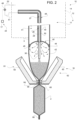
Figure 2 is an enlarged view of a detail of the packaging apparatus ofFigure 1 , with parts removed for clarity. -
Number 1 indicates as a whole a packaging machine for producing sealedpackages 2 of a pourable food product, such as pasteurized milk or fruit juice, from atube 3 of a web 4 of packaging material. In particular, in use,tube 3 extends along a longitudinal axis, in particular having a vertical orientation. - Web 4 of packaging material has a multilayer structure, and comprises a layer of fibrous material, normally paper, covered on both sides with respective layers of heat-seal plastic material, e.g. polyethylene.
- Preferably, web 4 also comprises a layer of gas- and light-barrier material, e.g. aluminium foil or ethylene vinyl alcohol (EVOH) film, and at least a first and a second layer of heat-seal plastic material. The layer of gas- and light-barrier material is superimposed on the first layer of heat-seal plastic material, and is in turn covered with the second layer of heat-seal plastic material. The second layer of heat-seal plastic material forms the inner face of
package 2 eventually contacting the food product. - A
typical package 2 obtained bypackaging apparatus 1 comprises a sealed longitudinal seam portion and a pair oftransversal seal portions 66, in particular a pair of top and bottom transversal seal portions 66 (i.e. oneseal portion 66 at an upper portion ofpackage 2 and anotherseal portion 66 at a lower portion of package 2). - With particular reference to
Figure 1 ,packaging machine 1 comprises aconveying device 5 for advancing in a known manner web 4 along a web advancement path P from a delivery station to a formingstation 9, at which, in use, web 4 is formed intotube 3. Conveyingdevice 5 is also configured to advancingtube 3 along a tube advancement path Q. -
Packaging machine 1 comprises anisolation chamber 10 having aninner environment 11, in particular an innersterile environment 11, containing a sterile gas, in particular sterile air, and being separated from anouter environment 12. -
Packaging machine 1 comprises atube forming device 13 extending along a longitudinal axis, in particular having a vertical orientation, and being arranged, in particular at formingstation 9, at least partially, preferably fully, withinisolation chamber 10 and being adapted to formtube 3 from the, in use, advancing web 4. -
Packaging machine 1 comprises a sealing device at least partially arranged withinisolation chamber 10 and being adapted to longitudinallyseal tube 3 formed bytube forming device 13. - Preferentially,
tube forming device 13 is adapted to gradually fold web 4 intotube 3, in particular by overlapping first and second edges with one another for forming a longitudinal seam portion oftube 3, in particular the longitudinal seam portion being, in use, sealed by activation of sealing device. - Preferentially,
conveying device 5 is adapted toadvance tube 3 and any intermediate oftube 3 along a tube advancement path Q, in particular from formingstation 9 to apackage forming unit 16. In particular, with the wording intermediates oftube 3 any configuration of web 4 is meant prior to obtaining the tube structure and after folding of web 4 bytube forming device 13 has started. In other words, the intermediates oftube 3 are a result of the gradual folding of web 4 so as to obtaintube 3, in particular by overlapping with one another a first edge of web 4 and a second edge of web 4, opposite to first edge. - Preferentially,
tube forming device 13 comprises at least two formingring assemblies 22, in particular arranged within isolation chamber 10 (in particular, within inner environment 11), being adapted to gradually fold in cooperation with one another web 4 intotube 3, in particular by overlapping edges with one another for forming longitudinal seam portion. In the specific case shown, a first formingring assembly 22 is arranged downstream of a second formingring assembly 22 along path Q. In particular, first and second formingring assemblies 22 are spaced apart from and parallel to one another. Furthermore, first and second formingring assemblies 22 are arranged coaxial to one another and define longitudinal axis oftube forming device 13. - Preferentially, sealing device comprises a sealing
head 21 adapted to interact withtube 3, for longitudinallysealing tube 3, in particular for sealing longitudinal seam portion. In particular, sealinghead 21 is adapted toheat tube 3, in particular along seam portion. Sealinghead 21 can be of the kind operating by means of induction heating or by a stream of heat or by means of ultrasound or other means. - Preferentially, sealing device comprises a pressuring assembly adapted to exert a mechanical force on
tube 3, in particular on the substantially overlapping edges oftube 3 so as to ensure sealing oftube 3 along seam portion. In particular, the pressuring assembly comprises an interaction roller and a counter-interaction roller adapted to exert a mechanical force onto seam portion from opposite sides thereof. In use, seam portion is interposed between interaction roller and the counter-interaction roller. Preferentially, interaction roller is supported by formingring assembly 22. -
Packaging machine 1 comprises a filling device 15 for continuously fillingtube 3 with the pourable product. - With particular reference to
Figures 1 and2 , filling device 15 comprise afilling pipe 27 being in fluid connection with a pourable product storage tank, which is adapted to store/provide for the pourable product to be packaged. - In particular,
filling pipe 27 is adapted to direct, in use, the pourable product intotube 3. Preferentially,filling pipe 27 is, in use, at least partially placed withintube 3 for continuously feeding the pourable product intotube 3. In particular,filling pipe 27 includes a linearmain pipe portion 28 extending withintube 3. - Even more particular,
main pipe portion 28 comprises anupper section 29 and alower section 30 coupled to one another (preferably, removably). In further detail,lower section 30 comprises an outlet opening from which the pourable product is fed, in use, intotube 3. -
Packaging machine 1 comprisespackage forming unit 16 which is adapted to shape, to transversally seal and to transversally cut the, in use, advancingtube 3 for formingpackages 2. In particular,package forming unit 16 is arranged downstream ofisolation chamber 10 andtube forming device 13 and sealing device along path Q. - With reference to
Figure 2 ,package forming unit 16 comprises: - a plurality of operative assemblies 61 (only one shown) and a plurality of counter-operative assemblies 62 (only one shown); and
- a track (not shown) adapted to advance the
operative assemblies 61 and thecounter-operative assemblies 62 along respective conveying paths. In particular, each of theoperative assembly 61 andcounter-operative assembly 62 advances cyclically along the respective conveying path. In even more particular, each of theoperative assembly 61 andcounter-operative assembly 62 is movable along said track independently from one another. - In more detail, each
operative assembly 61 is adapted to cooperate, in use, with one respectivecounter-operative assembly 62 for forming arespective package 2 fromtube 3. In particular, eachoperative assembly 61 and the respectivecounter-operative assembly 62 are adapted to shape, to transversally seal and, preferably also to transversally cut,tube 3 for formingpackages 2. - In further detail, each
operative assembly 61 and the respectivecounter-operative assembly 62 are adapted to cooperate with one another for forming arespective package 2 fromtube 3 when advancing along a respective operative portion of the respective conveying path. In particular, during advancement along the respective conveying path eachoperative assembly 61 and the respectivecounter-operative assembly 62 advance parallel to and in the same direction astube 3. - In more detail, each
operative assembly 61 and the respectivecounter-operative assembly 62 are configured to contacttube 3 when advancing along the respective operative portion of the respective conveying path. In particular, eachoperative assembly 61 and the respectivecounter-operative assembly 62 are configured to start to contacttube 3 at a (fixed) hit position. - Furthermore, each
operative assembly 61 andcounter-operative assembly 62 comprises: - a half-
shell 63 adapted to contacttube 3 and to at least partially define the shape ofpackages 2; - one of a sealing
element 64 or acounter-sealing element 65, adapted totransversally seal tube 3 betweenadjacent packages 2 for obtainingtransversal seal portions 66; and - one of a cutting element (not shown and known as such) or a counter-cutting element (not shown and known as such) for transversally cutting
tube 3 betweenadjacent packages 2, in particular between therespective seal portions 66. - In particular, each half-
shell 63 is adapted to be controlled between a working position and a rest position by means of a driving assembly. In particular, each half-shell 63 is adapted to be controlled into the working position with the respectiveoperative assembly 61 or the respectivecounter-operative assembly 62, in use, advancing along the respective operative portion. - It is noted that sealing
element 64 andcounter-sealing element 65 can be of the kind operating by means of induction heating or by a stream of heat or by means of ultrasound or other means. - According to a preferred non-limiting embodiment,
package forming unit 16 is of the type described in any of patent documentsEP3254980A1 ,EP3476751A1 in the name of the present Applicant. It is expressly understood that all the functional and structural features of the forming assembly of patent documentsEP3254980A1 ,EP3476751A1 can be applied to package formingunit 16 described herein. - With particular reference to
Figures 1 and2 ,isolation chamber 10 comprises a housing 14 (only schematically shown) delimiting the inner environment 11 (i.e.housing 14 separatesinner environment 11 from outer environment 12). In particular,inner environment 11 comprises (i.e. contains) sterile gas, in particular the sterile air, at a given pressure. Preferentially, the given pressure is slightly above ambient pressure for reducing the risk of any contaminants enteringinner environment 11. In particular, the given pressure is about 100 Pa to 500 Pa (0,001 bar to 0,005 bar) above ambient pressure. - Preferentially,
packaging apparatus 1 comprises means (not shown and known as such) for feeding the sterile gas, in particular the sterile air, intoisolation chamber 10, in particularinner environment 11. - According to one or more embodiments of the present invention and with particular reference to
Figure 2 ,packaging apparatus 1 also comprises: - a delimiting
element 40 placed, in use, withintube 3 and designed to dividetube 3, in use, into afirst space 41 and asecond space 42; and - a pressurizing
device 43 adapted to direct, in particular to continuously direct, in use, a flow of sterile gas intosecond space 42 for obtaining a gas pressure withinsecond space 42 that is higher than the gas pressure withinfirst space 41. - In more detail,
first space 41 is delimited bytube 3, in particular the walls oftube 3, and delimitingelement 40. Furthermore,first space 41 opens up intoinner environment 11. Even more particular, delimitingelement 40 delimitsfirst space 41 at a downstream portion, in particular a bottom portion, offirst space 41 itself. - In more detail,
second space 42 is delimited, in use, bytube 3, in particular the walls oftube 3, delimitingelement 40 andtransversal seal portion 66. - In further detail,
first space 41 is arranged upstream ofsecond space 42 along tube advancement path Q. Even more particular,first space 41 is arranged upstream of delimitingelement 40 along path Q. In the specific example shown,second space 42 is placed belowfirst space 41. - In particular, as will become clear from the following description,
second space 42 defines a high-pressure zone withintube 3 andfirst space 41 defines a low-pressure zone withintube 3. - In the context of the present application, high-pressure zone (i.e. second space 42) is to be understood such that the internal pressure lies in a range of about 5kPa to 40kPa (0,05 bar to 0,4 bar), in particular of about 10kPa to 30 kPa (0,10 bar to 0,30 bar) above ambient pressure (i.e. the pressure within
second space 42 lies in a range of about 5kPa to 40kPa (0,05 bar to 0,4 bar), in particular of about 10kPa to 30 kPa (0,10 bar to 0,30 bar) above ambient pressure). In other words,second space 42 is overpressurized. - Low-pressure zone (i.e. first space 41) is to be understood such that the pressure is slightly higher than the ambient pressure. In particular, slightly higher than the ambient pressure means that the pressure lies in a range between 100 Pa to 500 Pa (0,001 bar to 0,005 bar) above ambient pressure.
- In further detail,
first space 41 is in (direct) fluidic connection withinner environment 11. Thus, sterile gas present infirst space 41 can flow toinner environment 11. - In particular, tube 3 (and its intermediates) lie at least partially within isolation chamber 10 (in particular, within inner environment 11).
- Preferentially, the pressure inside first space 41 (substantially) equals the given pressure present in
isolation chamber 10, in particular ininner environment 11. Preferentially, the pressure insidefirst space 41 ranges between 100 Pa to 500 Pa (0,001 bar to 0,005 bar) above ambient pressure. - Filling device 15, in
particular filling pipe 27, is adapted to direct the pourable product intosecond space 42. Thus, in use,second space 42 contains the pourable product and the pressurized sterile gas. The pressurized sterile gas provides for the required hydrostatic force needed for a correct forming of packages 2 (i.e. in other words, the sterile gas replaces the effect of the pourable product column within tube 3). - Advantageously, delimiting
element 40 is designed to provide, in use, for at least onefluidic channel 44, in particular having an annular shape, for fluidically connectingsecond space 42 withfirst space 41 allowing for, in use, a leakage flow of sterile gas fromsecond space 42 intofirst space 41. In particular, in use, the sterile gas leaks from second space 42 (the high-pressure zone) to first space 41 (the low-pressure zone) throughfluidic channel 44. By providing forfluidic channel 44 it is possible to control the gas pressure withinsecond space 42 with an increased accuracy. Preferentially delimitingelement 40 is designed such that, in use,fluidic channel 44 is provided by a gap between the inner surface oftube 3 and delimitingelement 40, in particular aperipheral portion 45 of delimitingelement 40. - In particular, pressurizing means 43 are configured to provide for a variable flow of sterile gas of about 10 to 200 Nm3/h, in particular of 20 to 180 Nm3/h, even more particular of about 25 to 150 Nm3/h.
- Preferentially, pressurizing means 43 are adapted to vary the flow of sterile gas in dependence of the sterile gas flowing from
second space 42 tofirst space 41, in particular through at leastfluidic channel 44. - Preferentially, pressurizing
device 43 is adapted to control the gas pressure withinsecond space 42 to range between 5 kPa to 40 kPa (0, 05 bar to 0, 40 bar), in particular between 10 kPa to 30 kPa (0,1 bar to 0,3 bar), above ambient pressure. - Advantageously, pressurizing
device 43 is designed such to provide for a closed sterile gas circuit frominner environment 11 intosecond space 42 and back intoinner environment 11. In more detail, pressurizingdevice 43 is adapted to withdraw sterile gas frominner environment 11, to pressurize (to compress) the sterile gas and to direct the pressurized (compressed) sterile gas intosecond space 42. - Preferentially, pressurizing
device 43 comprises apumping device 46 adapted to withdraw sterile gas frominner environment 11, to pressurize (to compress) the sterile gas and to direct the pressurized sterile gas intosecond space 42. Preferentially, pumpingdevice 46 is a rotary machine, even more particular a compressor. -
Packaging machine 1 also comprises acontrol unit 17 for controlling operation ofpackaging machine 1. - Preferably,
control unit 17 is adapted to control the operating parameters of pumpingdevice 46, in particular the compressor. As explained further below,control unit 17 is configured to control the operating parameters of pumpingdevice 46 as a function of at least one of the advancement speed of web 4 or the advancement speed of tube 3 (both advancement speeds are equal) or the format or the shape ofpackages 2 to be formed or the volume ofpackages 2 to be formed. - Preferably, the rotary machine, in particular the compressor is configured to operate at rotation speeds ranging between 10000 to 100000 rpm, in particular 20000 to 80000 rpm, even more particular 30000 to 60000 rpm.
- In the specific example disclosed,
control unit 17 is adapted to control the rotation speed of the rotary machine, in particular of the compressor as a function of at least one of the advancement speed of web 4 or the advancement speed oftube 3 or the format ofpackages 2 to be formed or the volume ofpackages 2 to be formed. - Preferably, the rotary machine, in particular the compressor is configured such that the pressure provided increases with increasing rotation speed.
- Preferably, the rotary machine, in particular the compressor is configured to allow for a variable flow of sterile gas by maintaining a substantially constant gas pressure within
second space 42, in particular as a function of the flow of gas fromsecond space 42 to first space 41 (through fluidic channel 44). - Preferably, pressurizing
device 43 comprise agas feeding pipe 48 being at least indirectly fluidically connected withinner environment 11 andsecond space 42 for directing the sterile gas frominner environment 11 intosecond space 42. In particular,gas feeding pipe 48 is directly fluidically connected withsecond space 42. Preferentially,gas feeding pipe 48 is at least indirectly connected with pumpingdevice 46, in particular the compressor. - In more detail,
gas feeding pipe 48 comprises at least amain portion 49, which, in use, extends withintube 3. In particular,main portion 49 extends parallel tomain pipe portion 28. Even more particular, at leastmain portion 49 andmain pipe portion 28 are coaxial to one another. - In the specific example shown, filling
pipe 27 extends at least partially withingas feeding pipe 48. Alternatively,gas feeding pipe 48 could at least partially extend within fillingpipe 27. - In more detail, at least
main pipe portion 28 of filling pipe extends at least partially withinmain portion 49 of gas feeding pipe. - In particular, the cross-sectional diameter of
main pipe portion 28 of filling pipe is smaller than the cross-section diameter ofmain portion 49 of gas feeding pipe. - Preferentially,
gas feeding pipe 48 and fillingpipe 27 define/delimit anannular conduit 50 for the sterile gas to be fed intosecond space 42. In particular,annular conduit 50 is delimited by the inner surface ofgas feeding pipe 48 and the outer surface of fillingpipe 27. - In other words, in use, the sterile gas is directed into
second space 42 throughannular conduit 50. - Pressurizing means 43 also comprise:
- a
first gas conduit 51 being in direct fluidic connection with pumpingdevice 46, in particular the rotary machine, even more particular the compressor and thegas feeding pipe 48; and - a
second gas conduit 52 being in direct fluidic connection withinner environment 11 andpumping device 46, in particular the rotary machine, even more particular the compressor. - Thus, in use, sterile gas is withdrawn from
inner environment 11 throughgas conduit 52, is then pressurized (compressed) by pumpingdevice 46, and is then directed intosecond space 42 throughgas conduit 51 andgas feeding pipe 48. - Preferentially, delimiting
element 40 is removably connected to at least a portion of fillingpipe 27 and/orgas feeding pipe 48. In particular, delimitingelement 40 is connected to at least a portion of fillingpipe 27 and/orgas feeding pipe 48 in a floating manner (i.e. with play). In particular, in a floating manner means that delimitingelement 40 is adapted to(slightly) move parallel to tube advancement path Q. In other words, delimitingelement 40 is adapted to (slightly) move parallel to the, in use, advancingtube 3. - With particular reference to
Figure 1 ,packaging machine 1 also comprises atensioning device 32 configured to control the tension oftube 3. In particular the tension oftube 3 may be controlled in dependence of cyclic advancement speed of web 4 and/ortube 3 and/or in dependence of the operation ofpackage forming unit 11. - In particular, tensioning
device 32 is arranged upstream oftube forming device 13 along web advancement path P and is configured to control the tension oftube 3, and in particular of the portion of web 4 extending betweentensioning device 32 andtube forming device 13. Even more particular, tensioningdevice 32 is arranged upstream oftube forming device 13 and downstream of the sterilization station and/or the sterilization device. - Advantageously,
control unit 17 is configured to control operation oftensioning device 32. - With particular reference to
Figures 1 ,tensioning device 32 comprises: - a
main drive roller 33 rotatable around a main rotation axis; and a - a main drive motor, in particular a servo motor, connected to
main drive roller 33 and configured to actuate rotation ofmain drive roller 33 around main rotation axis. - According to a preferred non-limiting embodiment,
tensioning device 32 further comprises: - an
auxiliary drive roller 35 rotatable around an auxiliary rotation axis; and - an auxiliary drive motor, in particular an auxiliary servo motor, connected to
auxiliary drive roller 35 and configured to actuate and/or control rotation ofauxiliary drive roller 35 around auxiliary rotation axis. - According to a preferred non-limiting embodiment,
auxiliary drive roller 35 andmain drive roller 33 are spaced apart along web advancement path P, in particular withauxiliary drive roller 35 being arranged upstream ofmain drive roller 33. - According to a preferred non-limiting embodiment,
tensioning device 32 further comprises: - a main counter-roller 36 rotatable around a central axis and being arranged adjacent, in particular peripherally adjacent, even more particular tangential, to
main driver roller 33; and - an
auxiliary counter-roller 37 rotatable around a central axis and being arranged adjacent, in particular peripherally adjacent, even more particular tangential, toauxiliary drive roller 35. - According to a preferred non-limiting embodiment, and according to the relative arrangement of
auxiliary drive roller 35 andmain drive roller 33,auxiliary counter-roller 37 is arranged upstream ofmain counter-roller 36 along web advancement path P. - In particular, in use, web 4 is interposed and/or advances between main counter-roller 36 and
main drive roller 33, and in particular between auxiliary counter-roller 37 andauxiliary drive roller 35. - Advantageously,
control unit 17 is configured to control main drive motor such that an angular speed ofmain drive roller 33 is cyclically varied such to control the tension oftube 3, and in particular also of the portion of web 4 extending betweenmain drive roller 33 andtube forming device 13. - In particular, in the context of the present description, the term "cyclically varied" indicates that the angular speed and/or the angular acceleration of
main drive roller 33 follows respectively a time-dependent speed profile and/or time-dependent acceleration profile, which repeat(s) according to a defined and/or determined and/or given frequency. - In other words,
control unit 17 is configured to control main drive motor such that the angular speed and/or the angular acceleration ofmain drive roller 33 is cyclically varied according to respectively a time-dependent speed profile and/or acceleration profile, which repeats according to a defined operation frequency. In particular, the time-dependent speed profile is defined according to a cycle of the production of apackage 2 and/or the operation ofpackage forming unit 16. - In particular, controlling the angular speed and/or the angular acceleration of
main drive roller 33 around the respective rotation axis (and the respective main drive motor) according to respectively a cyclic speed profile and/or acceleration profile is advantageous as the forces acting ontube 3 during the formation ofpackages 2 are cyclic. - According to a preferred non-limiting embodiment,
control unit 17 is configured to control main drive motor such that the angular speed and/or the angular acceleration ofmain drive roller 33 is varied and/or controlled as a function of the operation ofpackage forming unit 11 and/or as a function of the package forming cycle and/or the forces acting ontube 3 and/or the operation of filling device 15 and the filling oftube 3. - In particular, the package forming cycle is substantially determined by the interaction of
operative assemblies 61 andcounter-operative assemblies 62, in particular of the respective half-shells 63, sealingelements 64 andcounter-sealing elements 65, withtube 3. - It should be noted that operation of package forming unit 16 (and the interaction of
operative assemblies 61 andcounter-operative assemblies 62 with tube 3) determines a cyclic advancement speed of web 4 (in particular of the portion of web 4 downstream of tensioning device 32) and/ortube 3. In particular, the cyclic advancement speed profile is a repetition (according to a defined frequency) of the advancement speed of web 4 and/ortube 3 during the formation of onesingle package 2. - According to a preferred non-limiting embodiment,
control unit 17 is also configured to control the auxiliary drive motor and main drive motor such that afree loop 38 of web 4 expands and/or advances, in use, betweenauxiliary drive roller 35 andmain drive roller 33. - With respect to the present invention, the term
free loop 38 indicates that the portion of web 4 expanding and/or advancing betweenauxiliary drive roller 35 andmain drive roller 33 is not subjected to any tension and defines and/or formsfree loop 38; i.e. the portion of web 4 defining and/or formingfree loop 38 is exposed to no tensional forces and/or is free of any tensional forces. In other words,free loop 38 is a tension-free portion of web 4. - Preferentially but not necessarily,
control unit 17 is configured to control the auxiliary drive motor such that an angular speed ofauxiliary drive roller 35 is such to maintain and/or control, in particular the extension of,free loop 38 expanding and/or advancing betweenauxiliary drive roller 35 andmain drive roller 33. - In particular, while, in use, the angular speed of
auxiliary drive roller 35 substantially controls the extension of the respectivefree loop 38, the angular speed ofmain drive roller 33 substantially controls the tension oftube 3. - According to a preferred non-limiting embodiment,
packaging machine 1 further comprises a sterilization apparatus for sterilizing at least a portion of web 4, preferentially at least a first face, even more preferentially the first face and a second face, in particular at a sterilization station. Preferentially, the sterilization station is arranged upstream of tube forming station along web advancement path P. Preferentially, the sterilization station is in fluid connection with theisolation chamber 10. - In particular, irradiation device comprises at least a first irradiation emitter, in particular a first electron beam emitter, configured to direct the sterilizing irradiation, in particular the electromagnetic irradiation, even more particular the electron beam irradiation on the first face of web 4 of packaging material. Preferentially irradiation device also comprises a second irradiation emitter, in particular a second electron beam emitter, configured to direct the sterilizing irradiation, in particular the electromagnetic irradiation, even more particular the electron beam irradiation, in use, on the second face of web 4 of packaging material.
- Preferably, the irradiation device is of the type described in patent documents
EP3549878A1 andEP3549613A1 , in the name of the present Applicant. It is expressly understood that all the functional and structural features of the apparatus of patent documentsEP3549878A1 andEP3549613A1 can be applied to the irradiation device of the machine described herein. - According to a preferred non-limiting embodiment,
packaging machine 1 further comprises a folding unit configured to receive the formed and sealedpackages 2 from thepackage forming unit 16 and for producing folded packages. - It should be noted that each
package 2 produced by the package forming unit 16 (so called "pillow package") comprises a main portion, and first and second end portions arranged on respective opposite sides of said main portion; said first end portion comprising a first fin and a pair of first flaps projecting laterally from said main portion. Second end portion comprising a second fin and a pair of second flaps projecting laterally from said main portion. In particular, first fin has a rectangular shape and projects from an (upper)transversal seam portion 66 and second fin has a rectangular shape and projects from another (lower)transversal seam portion 66. First end portion tapers from the main portion towards first fin, and second end portion tapers from main portion towards second fin. First flaps have a substantially triangular shape and project from opposite sides of first end portion, and second flaps have a substantially triangular shape and project from opposite sides of second end portion. - Folding unit substantially comprises:
- an endless conveyor for feeding
packages 2 continuously along a folding path from a supply station to an output station; - first folding means which cooperate cyclically with each
package 2 to flatten first end portion, fold relative first fin onto first end portion, and bend first flaps onto main portion towards the second end portion; - second folding means for flattening second end portion, folding second fin onto second end portion and folding second flaps onto the second fin.
- Preferably, folding unit further comprises a heating device acting on bent first and second flaps to melt the external layer of the packaging material and seal the flaps before they are pressed against main portion and second fin, respectively.
- Preferably, folding unit further comprises a pressing device cooperating with each
package 2 to hold flaps onto flattened fin as flaps cool. Heating device is, in particular, arranged between folding means and pressure device along folding path. - In particular, heating device comprises: an assembly air device; a pair of first nozzles connected to assembly air device and adapted to direct hot air onto first flaps of each package before each
package 2 reaches pressing device; and a pair of second nozzles connected to assembly and adapted to direct hot air onto second flaps of eachpackage 2. - Preferably, the folding unit is of the type described in patent document
EP3549613A1 , in the name of the present Applicant. It is expressly understood that all the functional and structural features of the apparatus of patent documentEP3549613A1 can be applied to the folding unit described herein. - According to a preferred non-limiting embodiment,
packaging machine 1 further comprises a strip applicator, configured to apply a sealing strip onto the web of a packaging material. The strip applicator comprises an advancement device configured to advance the sealing strip along a strip advancement path and towards and onto the web 4 of packaging material, before formation oftube 3. The strip applicator comprises a heat distribution device configured to direct a stream of the heated gas (in particular, air) onto the web of multilayer packaging material and/or onto the sealing strip. The strip applicator comprises an application device configured to apply the sealing strip onto the web of multilayer packaging material. - Preferably, the strip applicator is of the type described in patent document
EP4137295A1 , in the name of the present Applicant. It is expressly understood that all the functional and structural features of the apparatus of patent documentEP4137295A1 can be applied to the folding unit described herein. - According to one or more embodiments, the
packaging machine 1 is configured to receive the pourable product from an upstream equipment and/or to transfer the formed and sealed (and folded) packages 2 to a downstream equipment. - According to one aspect of the present disclosure, a packaging line is provided, said packaging line comprising the
packaging machine 1 and at least one of the upstream equipment and the downstream equipment. - The upstream equipment is configured to provide the pourable product to be filled. The upstream equipment may include one or more of the following equipment: tank, separator, steam injector, heat exchanger, homogenizer, mixer, filtration system, deaerator.
- The downstream equipment is configured to receive the formed and sealed (and folded) packages 2 and to operate further actions on the formed and sealed
packages 2. In particular, the downstream equipment receives thepackages 2 produced by the folding unit of thepackaging machine 1. - In an embodiment, the downstream equipment includes a cardboard packer configured to group and pack a plurality of formed and sealed
packages 2 into a carton. For example, the cardboard packer may be of the type described in patent documentsWO2021123263A1 andWO2021089404A1 , in the name of the present Applicant. It is expressly understood that all the functional and structural features of the cardboard packer of patent documentsWO2021123263A1 andWO2021089404A1 can be applied to the cardboard packer described herein. - In an embodiment, the downstream equipment includes an accumulator configured to store a plurality of packages. For example, the accumulator may be of the type described in patent document
WO2005102880A1 . It is expressly understood that all the functional and structural features of the accumulator of patent documentWO2005102880A1 can be applied to the accumulator described herein. - In an embodiment, the downstream equipment includes a cap applicator configured to apply a cap or lid onto the each one of the formed and sealed
package 2. According to some embodiments, cap applicator is also configured to weld or glue the applied cap or lid onto the formed and sealedpackage 2. - In an embodiment, cap applicator is configured to apply lids to necks of
packages 2. The cap applicator may comprise: a conveying device for advancing the packages along a path in an advancement direction; a group of applying heads, each applying head being arranged to apply, in particular to screw, a lid onto a corresponding neck; a movement device for moving the group of applying heads along the advancement direction, so that each applying head is coupled to a corresponding neck along a portion of said path; wherein the movement device is configured to act on a common support element supporting the applying heads of said group, so as to move synchronously the applying heads along the advancement direction. - For example, the cap applicator may be of the type described in patent document
WO2017060058A1 . in the name of the present applicant. It is expressly understood that all the functional and structural features of the cap applicator of patent documentWO2017060058A1 can be applied to the cap applicator described herein. - According to an aspect of the present disclosure, the
control unit 17 is configured to control the conveyingdevice 5 and/or thetensioning device 32 and/or thepackage forming unit 16 so to vary and/or change an advancement speed of thetube 3 and a release speed of the formed and sealedpackages 2. - Preferably, the
control unit 17 is configured to control the pressurizing device 43 (in particular thepumping device 46, even more in particular the compressor) so to vary and/or change the second gas pressure. Preferably thecontrol unit 17 controls the pressurizingdevice 43 such that a variation (namely, an extent of variation) of said second gas pressure is dependent on a variation (namely, an extent of variation) of said advancement speed and/or release speed, and/or controls the conveyingdevice 5 and thetensioning device 32 and thepackage forming unit 16 so that a variation (namely, an extent of variation) of said advancement speed and/or release speed is dependent on a variation (namely, an extent of variation) of said second gas pressure. Preferably, the variation in said advancement speed and/or release speed is simultaneous with the variation in said second gas pressure. - In particular, the
control unit 17 is configured to control the conveyingdevice 5 and thetensioning device 32 and thepackage forming unit 16 so to actuate a variation and/or a change in the advancement speed of the tube and in the release speed of the formed and sealed packages and, accordingly, actuate a variation and/or a change in the second gas pressure. Preferably, at each variation in the advancement speed of thetube 3 thecontrol unit 17 also controls a corresponding variation in the second gas pressure. - It is noted that a change in the advancement speed of the tube would normally result in a change in the tension of the
tube 3 and in a change in the tension of thepackages 2. If the tension oftube 3 is too high, the tube tends to collapse so that there is no more space for the pourable product. But if the tension ofpackages 2 is too low, thepackage 2 cannot withstand the operations of thepackage forming unit 16 and/or the folding unit. Thus, it is desired to keep the tension of the tube and the tension of the packages approximately constant (namely, allow that they vary only to a limited extent). - It is also noted that, as the hydrostatic pressure of the pourable product filled into the tube is determined by the second gas pressure, changing the second gas pressure causes a change in the pressure of the pourable product filled into the tube and, consequently, a change in the pressure of the pourable product contained in the formed packages 2. It is evident that such a change in the pressure of the pourable product influences the tension of the tube and the tension of the packages.
- So, in order to keep the tension of the tube and the tension of the packages approximately constant, the
control unit 17 when controlling a change in the advancement speed, also controls a change in the second gas pressure. In such a way, the change in the second gas pressure (and in the pourable product) always compensates for the change in the advancement speed of thetube 3. - As a result, the quality of the
packages 2 obtained is good at any advancement speed of the tube and even in the transient phases when the advancement speed is varied from one value to one another. As "quality of the packages" it is here meant that the values of a number of parameters of the packages, such as the weight, the dimensions, the surface appearance (namely, the number and entity of wrinkles on the external surface of the package), remain into predefined acceptable values so that the packages are not discarded. - It is here underlined that the possibility to not discard the packages in the transient phases when the advancement speed is varied from one value to one another improves sustainability of the machine, as the production waste is reduced.
- Preferably, the
control unit 17 has access to a database including a plurality of values of the advancement speed and/or release speed and a corresponding plurality of values of the second gas pressure. In said database, to each value of the advancement speed a corresponding value of the second gas pressure is associated. Thecontrol unit 17 is then configured to dynamically control the conveyingdevice 5 and/or thetensioning device 32 and/or thepackage forming unit 16 and the pressurizingdevice 43 as a function of the values contained in the database. In particular, when thecontrol unit 17 controls a change in the advancement speed from an initial value of advancement speed to a target value of advancement speed, it consults the database to extract the value of the second gas pressure corresponding the target value of advancement speed, and controls the pressurizingdevice 43 such that in thesecond space 42 said value of the second gas pressure corresponding the target value of advancement speed is reached. - According to one or more embodiments, for each value of the advancement speed a plurality of values of the second gas pressure are stored in the database, each one corresponding to a format or shape of the package to be formed. The
control unit 17 is configured to receive an information representative of the format or shape of the package to be formed and to extract, for each value of the advancement speed, the corresponding value of the second pressure relative to the format or shape of the package to be formed. Hence, thecontrol unit 17 receives as input the information representative of the format or shape of the package to be formed and the information regarding the target value of the advancement speed to be reached, and extracts from the database the corresponding value of the second gas pressure; so, thecontrol unit 17 simultaneously controls: - the conveying
device 5 and/or thetensioning device 32 and/or thepackage forming unit 16 so to vary the advancement speed of thetube 3 till said target value is reached, and - Inventors have noted that, in order to keep the tension of the tube approximately constant, the second gas pressure needs to be increased when the advancement speed is increased. In other words, the advancement speed and the second gas pressure are (approximately) proportional to one another. The
control unit 17 is configured to increase the second gas pressure when controlling an increase of the advancement speed and/or is configured to decrease the second gas pressure when controlling a decrease of the advancement speed. - As mentioned above, the
package forming unit 16 is configured to operate cyclically leading to a cyclic profile of the advancement speed of the tube 3 (and of the release speed of the packages 2). Consequently, thecontrol unit 17 is configured to control the main drive motor of thetensioning device 32, such that an angular speed of themain drive roller 33 is cyclically varied, and an advancement speed of the web 4 repeats according to a defined frequency. - The
control unit 17 is configured to control the conveyingdevice 5 and/or thetensioning device 32 and/or thepackage forming unit 16 so to modify said cyclic profile of the advancement speed of the tube 3 (and of the release speed of thepackages 2. In particular,control unit 17 is configured to modify the cyclic profile and/or said frequency of the angular speed of themain drive roller 33 in order to modify the cyclic profile of the advancement speed of thetube 3. - The modification of the cyclic profile of the advancement speed may include a variation in the frequency of the cycle and/or a modification of the values. In particular, in the context of the present disclosure, when "a variation in the advancement speed" is mentioned, a variation within the cyclic profile and/or a modification of the cyclic profile of the are meant.
- According to one or more aspects of the present disclosure, the
control unit 17 is configured to control the pressurizingdevice 43 to vary the second gas pressure according to a modification of the cyclic profile of the advancement speed of thetube 3. - Preferably, the
control unit 17 is configured to control the sealing device so as to change a sealing power delivered by the sealing device, as a function of said variation in said advancement speed of thetube 3 and/or release speed of thepackages 2. In particular,control unit 17 is configured to control sealinghead 21 so to vary the heating power delivered on the longitudinal seam portion, as a function of said variation in said advancement speed of thetube 3 and/or release speed of thepackages 2. In particular, thecontrol unit 17 is configured to increase the heating power of sealinghead 21, when increasing said advancement speed of thetube 3 and/or release speed of thepackages 2. - Also,
control unit 17 may be configured to control transversal sealing assembly (i.e.operative assembly 61 and counter-operative assembly 62) so to vary the heating power delivered ontotransversal seal portions 66, as a function of said variation in said advancement speed of thetube 3 and/or release speed of thepackages 2. In particular, thecontrol unit 17 is configured to increase the heating power of transversal sealing assemblies, when increasing said advancement speed of thetube 3 and/or release speed of thepackages 2. - Also,
control unit 17 may be configured to control the heat distribution device of the strip applicator so to vary the heating power delivered onto the strip and/or the web 4 of packaging material, before formation oftube 3. In particular, thecontrol unit 17 is configured to increase the heating power of the strip applicator, when increasing said advancement speed of thetube 3 and/or release speed of thepackages 2. - Preferably,
control unit 17 is further configured to control the filling device 15 so as to change an output rate of the pourable product, as a function of said variation in said advancement speed and/or release speed. In particular,control unit 17 is configured to increase the output rate of the pourable product when increasing the advancement speed and/or release speed. - Preferably,
control unit 17 is further configured to control the sterilization apparatus so to change an irradiation power delivered by said sterilization apparatus, as a function of said variation in said advancement speed and/or release speed. In the context of the present disclosure, "irradiation power" means a quantity of radiation (in particular, a quantity of electrons) emitted per unit of time. In particular,control unit 17 is configured to increase the irradiation power delivered by said sterilization apparatus when increasing the advancement speed and/or release speed. In even more particular, thecontrol unit 17 is configured to increase the irradiation power delivered by said sterilization apparatus when increasing the advancement speed and/or release speed such that an electron dose delivered on the packaging material remains constant. - Preferably,
control unit 17 is configured to control a speed of the endless conveyor of the folding unit as a function of the advancement speed and/or release speed. Preferably,control unit 17 is configured to control a heating device of the folding unit so as to change the delivered heating power as a function of the advancement speed and/or release speed. - Preferably, the
control unit 17 is configured to receive input data representative of an operational condition of the upstream equipment and/or downstream equipment and to control the advancement speed of thetube 3 and the second gas pressure as a function of the input data. For example, the input data may be representative of a slowdown of the upstream equipment and/or downstream equipment; then, thecontrol unit 17 is configured to reduce the advancement speed of thetube 3 and to reduce the second gas pressure such that the filling machine adapts its speed to the speed of the upstream equipment and/or downstream equipment (without need to stop the machine). When the production speed is reduced, the producedpackages 2 still have a good quality (thanks to the adaptation of the second gas pressure) and so they are not discarded. In another example, the input data may be representative of a stop (or a planned stop) of the upstream equipment and/or downstream equipment; then, thecontrol unit 17 is configured to reduce the advancement speed of thetube 3 to a minimum possible value and to reduce the second gas pressure. - The present disclosure also provides a method for forming a plurality of sealed
packages 2 filled with a pourable product. Preferably, the method is carried out by the machine which is object of the present disclosure. - The method includes a step of advancing a web 4 of packaging material along a web advancement path P, through a conveying
device 5. - The method includes a step of forming a
tube 3 from the advancing web 4 of packaging material, through atube forming device 13 extending along a longitudinal axis and being at least partially arranged within aninner environment 11 of anisolation chamber 10 containing a sterile gas. - The method includes a step of advancing the
tube 3 along a tube advancement path Q, according to an advancement speed. A delimitingelement 40 is arranged within the tube and divides the tube in afirst space 41 being in fluidic connection with theinner environment 11 and asecond space 42 being arranged downstream of thefirst space 41 along the tube advancement path Q. - The method includes a step of directing a variable flow of sterile gas into the
second space 42, through a pressurizing device, for obtaining a second gas pressure within thesecond space 42, said second gas pressure being higher than a first gas pressure within thefirst space 41. - The method includes a step of longitudinally sealing the tube formed by the
tube forming device 13, through a sealing device being at least partially arranged within theinner environment 11 of theisolation chamber 10. - The method includes a step of continuously filling the
tube 3 with a pourable product, through a filling device 15. - The method includes a step of forming and transversally sealing (and cutting) the
packages 2 from the advancingtube 3, through apackage forming unit 16. - The method includes a step of controlling the tension of the web 4 of packaging material and/or of the
tube 3, through atensioning device 32. - The method includes a step of varying the advancement speed of the tube and/or a release speed of the formed and sealed packages.
- Preferably, the method further includes a step of varying the second gas pressure, wherein a variation in said second gas pressure is dependent on a variation in said advancement speed and/or release speed and/or vice versa.
- Preferably, the method further includes a step of receiving the pourable product from an upstream equipment. Preferably, the method further includes a step of transferring the formed and sealed
packages 2 to a downstream equipment. Said variation in the advancement speed of thetube 3 and/or release speed of the formed and sealedpackages 2 and/or said variation in the second gas pressure are dependent on an operational condition of the upstream equipment and/or the downstream equipment. - Preferably, the method further includes a step of controlling the sealing device so as to change a sealing power delivered by the sealing device, as a function of said variation in said advancement seed and/or release speed.
- Preferably, the method further includes a step of controlling the filling device 15 so as to change an output rate of the pourable product, as a function of said variation in said advancement speed and/or release speed.
- Preferably, the method further includes a step of sterilizing at least a first face of the web 4 of packaging material through a sterilization apparatus comprising an irradiation device configured to direct a sterilizing electromagnetic irradiation onto at least the first face while, in use, advancing along a sterilization portion of the web advancement path. Preferably, the method further includes a step of controlling the sterilization apparatus so to change an irradiation power delivered by said sterilization apparatus, as a function of said variation in said advancement speed and/or release speed.
Claims (18)
- A packaging machine (1) for forming a plurality of sealed packages (2) filled with a pourable product, comprising:- a conveying device (5), configured to advance a web (4) of packaging material along an advancement path (P);- an isolation chamber (10) separating an inner environment (11) containing a sterile gas from an outer environment (12);- a tube forming device (13) extending along a longitudinal axis, being at least partially arranged within the isolation chamber (10) and being configured to form a tube (3) from the, in use, advancing web (4) of packaging material;- a delimiting element (40) arranged, in use, within the tube (3) and designed to divide the tube (3) in a first space (41) being in fluidic connection with the inner environment (11) and a second space (42) being arranged downstream of the first space (41) along the tube advancement path;- a pressurizing device (43) configured to direct, in use, a flow of sterile gas into the second space (42) for obtaining a second gas pressure within the second space (42) that is higher than a first gas pressure within the first space (41);- a sealing device, being at least partially arranged within the isolation chamber and being configured to longitudinally seal the tube formed by the tube forming device;- a filling device (15) configured to continuously fill the tube (3) with the pourable product, wherein the filling device (15) is configured to direct the pourable product into the second space (42);- a package forming unit (16) configured to form and transversally seal the packages (2) from the, in use, advancing tube (3);- a tensioning device (32) configured to control the tension of the web (4) of packaging material and/or of the tube (3);- a control unit (17) configured to control operation of the packaging machine (1);characterized in that the control unit (17) is configured to control:- the conveying device (5) and/or the tensioning device (32) and/or the package forming unit (16) so to vary an advancement speed of the tube (3) and a release speed of the formed and sealed packages (2), and- the pressurizing device (43) so to vary the second gas pressure,wherein a variation in said second gas pressure is dependent on a variation in said advancement speed and/or release speed.
- The packaging machine (1) according to claim 1, wherein the control unit (17) has access to a database including_- a plurality of values of the advancement speed and/or release speed and- a corresponding plurality of values of the second gas pressure,wherein to each value of the advancement speed a corresponding value of the second gas pressure is associated, wherein the control unit (17) is configured to dynamically control the conveying device (5), the tensioning device (32), the package forming unit (16) and the pressurizing device (43) as a function of the values contained in the database.
- The packaging machine (1) according to 2, wherein the control unit (17) is configured to increase the second gas pressure responsive to an increase of the advancement speed and/or to decrease the second gas pressure responsive to a decrease of the advancement speed.
- The packaging machine (1) according to any one of the previous claims, wherein the package forming unit (16) is configured to operate cyclically leading to a cyclic profile of the advancement speed of the tube (3), wherein the control unit (17) is configured to control the conveying device (5) and/or the tensioning device (32) and/or the package forming unit (16) so to modify said cyclic profile of the advancement speed of the tube (3), wherein the control unit (17) is configured to control the pressurizing device (43) to vary the second gas pressure according to a modification of the cyclic profile of the advancement speed of the tube (3).
- The packaging machine (1) according to claim 4, wherein the tensioning device (32) is arranged upstream of the tube forming device (13) along the web advancement path (P) and comprises:- a main drive roller (33) rotatable around a main rotation axis;- a main drive motor configured to actuate rotation of the main drive roller (33) around the main rotation axis;wherein the control unit (17) is configured to control the main drive motor such that an angular speed of the main drive roller (33) is cyclically varied, and an advancement speed of the web (4) repeats according to a defined frequency,wherein the control unit (17) is configured to modify the cyclic profile and/or said frequency of the angular speed of the main drive roller (33) in order to modify the cyclic profile of the advancement speed of the tube (3).
- The packaging machine (1) according to any one of the previous claims, wherein the control unit (17) is configured to control the sealing device so as to change a sealing power delivered by the sealing device, as a function of said variation in said advancement speed and/or release speed.
- The packaging machine (1) according to any one of the previous claims, wherein the control unit (17) is configured to control the filling device (15) so as to change an output rate of the pourable product, as a function of said variation in said advancement speed and/or release speed.
- The packaging machine (1) according to any one of the previous claims, comprising a sterilization apparatus having an irradiation device configured to sterilize at least a first face of the advancing web (4) of packaging material by directing a sterilizing irradiation onto at least the first face while, in use, advancing along a sterilization portion of the web advancement path,
wherein the control unit (17) is configured to control the sterilization apparatus so to change an irradiation power delivered by said sterilization apparatus, as a function of said variation in said advancement speed and/or release speed. - The packaging machine (1) according to any one of the previous claims, further comprising a folding unit configured to receive the formed and sealed packages (2) from the package forming unit (16) and for producing folded packages, wherein the folding unit comprises an endless conveyor for feeding packages (2) continuously along a folding path from a supply station to an output station, and folding means which cooperate, in use, with each package (2) to perform at least one folding operation on said package, wherein the control unit (17) is configured to control a speed of said endless conveyor as a function of the advancement speed and/or release speed.
- The packaging machine (1) according to any one of the previous claims, being configured to receive the pourable product from an upstream equipment and to transfer the formed and sealed packages (2) to a downstream equipment,
wherein the control unit (17) is configured to receive input data representative of an operational condition of the upstream equipment and/or downstream equipment and to control the advancement speed of the tube (3) and the second gas pressure as a function of the input data representative of an operational condition of the upstream equipment and/or downstream equipment. - The packaging machine (1) according to any one of the previous claims, wherein the delimiting element (40) is designed to provide, in use, at least one fluidic channel for fluidically connecting the second space (42) with the first space (41) and for allowing, in use, a leakage flow of sterile gas from the second space (42) into the first space (41),
wherein the pressurizing device (43) comprises at least one pumping device adapted to withdraw sterile gas from the inner environment (11), to pressurize the sterile gas and to direct the pressurized sterile gas into the second space (42) . - A packaging line including:- an upstream equipment configured to provide a pourable food product;- a packaging machine (1) according to any one of the previous claims, the packaging machine (1) being configured to receive the pourable product from the upstream equipment;- a downstream equipment configured to receive the formed and sealed packages from the packaging machine (1), wherein the control unit (17) of the packaging machine (1) is configured to control the conveying device (5) and/or the tensioning device and/or the package forming unit (16) so to vary an advancement speed of the tube (3), and to control the pressurizing device (43) so to vary the second gas pressure, responsive to receiving input data representative of an operational condition of the upstream equipment and/or downstream equipment.
- The packaging line according to claim 12, wherein the control unit (17) is configured to control a variation of the advancement speed of the tube (3) and a corresponding variation of the second gas pressure, as a function of the input data representative of the operational condition of the upstream equipment and/or downstream equipment
- The packaging line according to claim 12 or 13, wherein the upstream equipment includes one or more of the following equipment: tank, separator, steam injector, heat exchanger, homogenizer, mixer, filtration system, deaerator,
and/or the downstream equipment includes one or more of the following equipment:- a cardboard packer configured to group and pack a plurality of formed and sealed packages into a carton;- an accumulator configured to store a plurality of packages;- a cap applicator configured to apply a cap onto the each one of the formed and sealed packages. - A method for forming a plurality of sealed packages (2) filled with a pourable product, the method comprising the following steps:- advancing a web (4) of packaging material along a web advancement path (P), through a conveying device (5);- forming a tube (3) from the advancing web (4) of packaging material, through a tube forming device (13) extending along a longitudinal axis and being at least partially arranged within an inner environment (11) of an isolation chamber (10) containing a sterile gas;- advancing the tube (3) along a tube advancement path (Q) ;
wherein a delimiting element (40) is arranged within the tube and divides the tube in a first space (41) being in fluidic connection with the inner environment (11) and a second space (42) being arranged downstream of the first space (41) along the tube advancement path (Q);- directing a variable flow of sterile gas into the second space (42), through a pressurizing device, for obtaining a second gas pressure within the second space (42), said second gas pressure being higher than a first gas pressure within the first space (41);- longitudinally sealing the tube formed by the tube forming device (13), through a sealing device being at least partially arranged within the inner environment (11) of the isolation chamber (10);- continuously filling the tube (3) with a pourable product, through a filling device (15);- form and transversally seal the packages (2) from the advancing tube (3), through a package forming unit (16);- control the tension of the web (4) of packaging material and/or of the tube (3) through a tensioning device (32),characterized in that it further comprises the following steps:- varying an advancement speed of the tube (3) and a release speed of the formed and sealed packages (2),- varying the second gas pressure,wherein a variation in said second gas pressure is dependent on a variation in said advancement speed and/or release speed. - The method according to claim 15, wherein said step of varying the advancement speed of the tube (3) and the release speed of the formed and sealed packages, and said step of varying the second gas pressure, are simultaneous.
- The method according to claim 15 or 16, further comprising the following steps:- receiving the pourable product from an upstream equipment;- transferring the formed and sealed packages (2) to a downstream equipment,wherein said variation in the advancement speed of the tube (3) and/or release speed of the formed and sealed packages (2) and said variation in the second gas pressure are dependent on and/or function of an operational condition of the upstream equipment and/or the downstream equipment.
- The method according to any one of claims 15 to 17, further comprising one or more of the following steps:- controlling the sealing device so as to change a sealing power delivered by the sealing device, as a function of said variation in said advancement seed and/or release speed; and/or- controlling the filling device (15) so as to change an output rate of the pourable product, as a function of said variation in said advancement seed and/or release speed; and/or- sterilizing at least a first face of the web (4) of packaging material through a sterilization apparatus comprising an irradiation device configured to direct a sterilizing irradiation onto at least the first face while, in use, advancing along a sterilization portion of the web advancement path, and controlling the sterilization apparatus so to change an irradiation power delivered by said sterilization apparatus, as a function of said variation in said advancement speed and/or release speed.
Applications Claiming Priority (1)
| Application Number | Priority Date | Filing Date | Title |
|---|---|---|---|
| IT102023000007518A IT202300007518A1 (en) | 2023-04-18 | 2023-04-18 | PACKAGING APPARATUS FOR FORMING A MULTIPLE SEALED PACKAGES FILLED WITH A POURABLE PRODUCT |
Publications (1)
| Publication Number | Publication Date |
|---|---|
| EP4464608A1 true EP4464608A1 (en) | 2024-11-20 |
Family
ID=86851372
Family Applications (1)
| Application Number | Title | Priority Date | Filing Date |
|---|---|---|---|
| EP24169372.0A Pending EP4464608A1 (en) | 2023-04-18 | 2024-04-10 | A packaging apparatus for forming a plurality of sealed packages filled with a pourable product |
Country Status (4)
| Country | Link |
|---|---|
| EP (1) | EP4464608A1 (en) |
| CN (1) | CN120752181A (en) |
| IT (1) | IT202300007518A1 (en) |
| WO (1) | WO2024217950A1 (en) |
Citations (14)
| Publication number | Priority date | Publication date | Assignee | Title |
|---|---|---|---|---|
| WO1994010038A1 (en) * | 1992-10-30 | 1994-05-11 | Hayssen Manufacturing Company | Form-fill-seal packaging apparatus |
| DE60016446T2 (en) * | 1999-09-17 | 2005-04-07 | Tetra Laval Holdings & Finance S.A. | SYSTEM FOR MONITORING AND CONTROLLING THE STERILIZATION OF A SUBJECT |
| WO2005102880A1 (en) | 2004-04-02 | 2005-11-03 | Hartness International, Inc. | Differential drive spiral accumulator apparatus |
| WO2017060058A1 (en) | 2015-10-05 | 2017-04-13 | Tetra Laval Holdings & Finance S.A. | An applying unit for applying a lid onto a container |
| EP3254980A1 (en) | 2016-06-09 | 2017-12-13 | Tetra Laval Holdings & Finance S.A. | A packaging apparatus for forming sealed packages from a tube of packaging material |
| EP3476751A1 (en) | 2017-10-31 | 2019-05-01 | Tetra Laval Holdings & Finance S.A. | A packaging assembly for forming and sealing a plurality of packs containing a pourable food product |
| EP3549613A1 (en) | 2018-04-03 | 2019-10-09 | Tetra Laval Holdings & Finance S.A. | Sterilization apparatus, packaging machine having a sterilization apparatus and a method for sterilizing |
| EP3549878A1 (en) | 2018-04-03 | 2019-10-09 | Tetra Laval Holdings & Finance S.A. | Packaging machine and method for producing sealed packages |
| EP3456638B1 (en) | 2017-09-13 | 2020-06-24 | Tetra Laval Holdings & Finance S.A. | A packaging apparatus for forming sealed packages |
| EP3725689A1 (en) * | 2019-04-19 | 2020-10-21 | Tetra Laval Holdings & Finance S.A. | Packaging machine and method for producing sealed packages |
| WO2021089404A1 (en) | 2019-11-07 | 2021-05-14 | Tetra Laval Holdings & Finance S.A. | A carboard packer, and a blank picker for a cardboard packer |
| WO2021123263A1 (en) | 2019-12-19 | 2021-06-24 | Tetra Laval Holdings & Finance S.A. | A carboard packer, and a folding unit for a cardboard packer |
| EP3725692B1 (en) | 2019-04-19 | 2021-10-27 | Tetra Laval Holdings & Finance S.A. | Packaging machine and method for producing sealed packages |
| EP4137295A1 (en) | 2021-08-18 | 2023-02-22 | Tetra Laval Holdings & Finance S.A. | Heat distribution device for a packaging machine, strip application apparatus having a heat distribution device, packaging machine having a heat distribution device and packaging machine having a strip application apparatus |
-
2023
- 2023-04-18 IT IT102023000007518A patent/IT202300007518A1/en unknown
-
2024
- 2024-04-10 EP EP24169372.0A patent/EP4464608A1/en active Pending
- 2024-04-10 CN CN202480014719.2A patent/CN120752181A/en active Pending
- 2024-04-10 WO PCT/EP2024/059657 patent/WO2024217950A1/en not_active Ceased
Patent Citations (15)
| Publication number | Priority date | Publication date | Assignee | Title |
|---|---|---|---|---|
| WO1994010038A1 (en) * | 1992-10-30 | 1994-05-11 | Hayssen Manufacturing Company | Form-fill-seal packaging apparatus |
| DE60016446T2 (en) * | 1999-09-17 | 2005-04-07 | Tetra Laval Holdings & Finance S.A. | SYSTEM FOR MONITORING AND CONTROLLING THE STERILIZATION OF A SUBJECT |
| WO2005102880A1 (en) | 2004-04-02 | 2005-11-03 | Hartness International, Inc. | Differential drive spiral accumulator apparatus |
| WO2017060058A1 (en) | 2015-10-05 | 2017-04-13 | Tetra Laval Holdings & Finance S.A. | An applying unit for applying a lid onto a container |
| EP3254980A1 (en) | 2016-06-09 | 2017-12-13 | Tetra Laval Holdings & Finance S.A. | A packaging apparatus for forming sealed packages from a tube of packaging material |
| EP3456638B1 (en) | 2017-09-13 | 2020-06-24 | Tetra Laval Holdings & Finance S.A. | A packaging apparatus for forming sealed packages |
| EP3476751A1 (en) | 2017-10-31 | 2019-05-01 | Tetra Laval Holdings & Finance S.A. | A packaging assembly for forming and sealing a plurality of packs containing a pourable food product |
| EP3549613A1 (en) | 2018-04-03 | 2019-10-09 | Tetra Laval Holdings & Finance S.A. | Sterilization apparatus, packaging machine having a sterilization apparatus and a method for sterilizing |
| EP3549878A1 (en) | 2018-04-03 | 2019-10-09 | Tetra Laval Holdings & Finance S.A. | Packaging machine and method for producing sealed packages |
| EP3725689A1 (en) * | 2019-04-19 | 2020-10-21 | Tetra Laval Holdings & Finance S.A. | Packaging machine and method for producing sealed packages |
| EP3725692B1 (en) | 2019-04-19 | 2021-10-27 | Tetra Laval Holdings & Finance S.A. | Packaging machine and method for producing sealed packages |
| EP3725689B1 (en) | 2019-04-19 | 2021-11-10 | Tetra Laval Holdings & Finance S.A. | Packaging machine and method for producing sealed packages |
| WO2021089404A1 (en) | 2019-11-07 | 2021-05-14 | Tetra Laval Holdings & Finance S.A. | A carboard packer, and a blank picker for a cardboard packer |
| WO2021123263A1 (en) | 2019-12-19 | 2021-06-24 | Tetra Laval Holdings & Finance S.A. | A carboard packer, and a folding unit for a cardboard packer |
| EP4137295A1 (en) | 2021-08-18 | 2023-02-22 | Tetra Laval Holdings & Finance S.A. | Heat distribution device for a packaging machine, strip application apparatus having a heat distribution device, packaging machine having a heat distribution device and packaging machine having a strip application apparatus |
Also Published As
| Publication number | Publication date |
|---|---|
| CN120752181A (en) | 2025-10-03 |
| WO2024217950A1 (en) | 2024-10-24 |
| IT202300007518A1 (en) | 2024-10-18 |
Similar Documents
| Publication | Publication Date | Title |
|---|---|---|
| EP3456638B1 (en) | A packaging apparatus for forming sealed packages | |
| EP3623301B1 (en) | Packaging apparatus for forming sealed packages | |
| EP3656686B1 (en) | A packaging apparatus for forming sealed packages | |
| EP3656687B1 (en) | A method and a packaging apparatus for forming sealed packages | |
| EP3738894B1 (en) | A packaging apparatus for forming sealed packages | |
| EP3656688B1 (en) | A method and a packaging apparatus for forming sealed partially-filled packages | |
| EP4450403A1 (en) | A packaging apparatus for forming a plurality of sealed packages filled with a pourable product | |
| EP4464610A1 (en) | A packaging apparatus and method for forming a plurality of sealed packages filled with a pourable product | |
| WO2024217950A1 (en) | A packaging apparatus for forming a plurality of sealed packages filled with a pourable product | |
| EP4464609A1 (en) | A packaging apparatus and method for forming a plurality of sealed packages filled with a pourable product | |
| JP2026514670A (en) | Packaging machine that forms multiple sealed packages filled with fluid products | |
| JP2026514671A (en) | Packaging machine that forms multiple sealed packages filled with fluid products | |
| EP4606713A1 (en) | Packaging machine and method of sterilizing a packaging machine | |
| EP4563480A1 (en) | Packaging machine and method of cleaning a packaging machine | |
| EP4467470A1 (en) | A packaging machine for forming packages filled with a pourable product and packaging line having a packaging machine | |
| EP4410523A1 (en) | Package forming apparatus for a packaging machine and packaging machine for forming packages filled with a pourable product | |
| WO2024160636A1 (en) | Package forming apparatus for a packaging machine and packaging machine for forming packages filled with a pourable product |
Legal Events
| Date | Code | Title | Description |
|---|---|---|---|
| PUAI | Public reference made under article 153(3) epc to a published international application that has entered the european phase |
Free format text: ORIGINAL CODE: 0009012 |
|
| STAA | Information on the status of an ep patent application or granted ep patent |
Free format text: STATUS: THE APPLICATION HAS BEEN PUBLISHED |
|
| AK | Designated contracting states |
Kind code of ref document: A1 Designated state(s): AL AT BE BG CH CY CZ DE DK EE ES FI FR GB GR HR HU IE IS IT LI LT LU LV MC ME MK MT NL NO PL PT RO RS SE SI SK SM TR |
|
| STAA | Information on the status of an ep patent application or granted ep patent |
Free format text: STATUS: REQUEST FOR EXAMINATION WAS MADE |
|
| 17P | Request for examination filed |
Effective date: 20250520 |