EP4464605A1 - Systems and methods for inspecting aircraft - Google Patents
Systems and methods for inspecting aircraft Download PDFInfo
- Publication number
- EP4464605A1 EP4464605A1 EP24170375.0A EP24170375A EP4464605A1 EP 4464605 A1 EP4464605 A1 EP 4464605A1 EP 24170375 A EP24170375 A EP 24170375A EP 4464605 A1 EP4464605 A1 EP 4464605A1
- Authority
- EP
- European Patent Office
- Prior art keywords
- control unit
- images
- aircraft
- location
- inspection
- Prior art date
- Legal status (The legal status is an assumption and is not a legal conclusion. Google has not performed a legal analysis and makes no representation as to the accuracy of the status listed.)
- Granted
Links
Images




Classifications
-
- B—PERFORMING OPERATIONS; TRANSPORTING
- B64—AIRCRAFT; AVIATION; COSMONAUTICS
- B64F—GROUND OR AIRCRAFT-CARRIER-DECK INSTALLATIONS SPECIALLY ADAPTED FOR USE IN CONNECTION WITH AIRCRAFT; DESIGNING, MANUFACTURING, ASSEMBLING, CLEANING, MAINTAINING OR REPAIRING AIRCRAFT, NOT OTHERWISE PROVIDED FOR; HANDLING, TRANSPORTING, TESTING OR INSPECTING AIRCRAFT COMPONENTS, NOT OTHERWISE PROVIDED FOR
- B64F5/00—Designing, manufacturing, assembling, cleaning, maintaining or repairing aircraft, not otherwise provided for; Handling, transporting, testing or inspecting aircraft components, not otherwise provided for
- B64F5/60—Testing or inspecting aircraft components or systems
-
- G—PHYSICS
- G01—MEASURING; TESTING
- G01N—INVESTIGATING OR ANALYSING MATERIALS BY DETERMINING THEIR CHEMICAL OR PHYSICAL PROPERTIES
- G01N21/00—Investigating or analysing materials by the use of optical means, i.e. using sub-millimetre waves, infrared, visible or ultraviolet light
- G01N21/84—Systems specially adapted for particular applications
- G01N21/88—Investigating the presence of flaws or contamination
-
- B—PERFORMING OPERATIONS; TRANSPORTING
- B64—AIRCRAFT; AVIATION; COSMONAUTICS
- B64U—UNMANNED AERIAL VEHICLES [UAV]; EQUIPMENT THEREFOR
- B64U2101/00—UAVs specially adapted for particular uses or applications
- B64U2101/25—UAVs specially adapted for particular uses or applications for manufacturing or servicing
- B64U2101/26—UAVs specially adapted for particular uses or applications for manufacturing or servicing for manufacturing, inspections or repairs
-
- G—PHYSICS
- G01—MEASURING; TESTING
- G01N—INVESTIGATING OR ANALYSING MATERIALS BY DETERMINING THEIR CHEMICAL OR PHYSICAL PROPERTIES
- G01N21/00—Investigating or analysing materials by the use of optical means, i.e. using sub-millimetre waves, infrared, visible or ultraviolet light
- G01N21/84—Systems specially adapted for particular applications
- G01N21/88—Investigating the presence of flaws or contamination
- G01N21/8803—Visual inspection
-
- G—PHYSICS
- G01—MEASURING; TESTING
- G01N—INVESTIGATING OR ANALYSING MATERIALS BY DETERMINING THEIR CHEMICAL OR PHYSICAL PROPERTIES
- G01N21/00—Investigating or analysing materials by the use of optical means, i.e. using sub-millimetre waves, infrared, visible or ultraviolet light
- G01N21/84—Systems specially adapted for particular applications
- G01N21/88—Investigating the presence of flaws or contamination
- G01N21/95—Investigating the presence of flaws or contamination characterised by the material or shape of the object to be examined
- G01N21/9515—Objects of complex shape, e.g. examined with use of a surface follower device
-
- G—PHYSICS
- G06—COMPUTING OR CALCULATING; COUNTING
- G06T—IMAGE DATA PROCESSING OR GENERATION, IN GENERAL
- G06T7/00—Image analysis
- G06T7/0002—Inspection of images, e.g. flaw detection
- G06T7/0004—Industrial image inspection
- G06T7/001—Industrial image inspection using an image reference approach
Definitions
- Examples of the present disclosure generally relate to systems and methods for remotely inspecting aircraft.
- Aircraft are used to transport passengers and cargo between various locations. Numerous aircraft depart from and arrive at a typical airport every day.
- Aircraft are manually inspected before and after flights. For example, an individual views various portions of an aircraft for evidence of damage, such as caused by other objects, hail, lightning, and/or the like.
- Manual inspections generally require use of lifts, which risk potential falls, and can potentially cause damage to the aircraft, such as through accidental lift contact. Further, the process of such inspections is time and labor intensive. For example, one or more individuals operate the lift, as well as adroitly maneuver support equipment to access various areas of an aircraft. Also, manual documentation of inspection results typically produces non-digital information that may not be readily accessible.
- Certain examples of the present disclosure provide a system configured for an inspection of an aircraft at a first location.
- the system includes an imaging device configured to acquire one or more images of one of or more surfaces of the aircraft at the first location.
- a control unit is in communication with the imaging device.
- the control unit is configured to receive the one or more images.
- a user interface is in communication with the control unit.
- the user interface is at a second location that differs from the first location.
- the user interface includes a display.
- the control unit is configured to show the one or more images on the display. The inspection is performed at the second location.
- the inspection can include one or more of a general visual inspection of the aircraft, a lightning strike inspection of the aircraft, or a hail damage inspection of the aircraft.
- control unit is configured to modify the one or more images based on at least one characteristic of the display.
- control unit is configured to calculate optical requirements of the display to preserve an optical resolution that matches human eye inspection performance of the aircraft.
- control unit is configured to model human vision performance by applying calculations of human eye resolving power to establish a baseline for replicating capabilities on the display.
- control unit is configured to partition the one or more images into parts shown on the display.
- the control unit can be further configured to store the one or more images in a memory.
- a mobile cart includes the imaging device.
- a drone includes the imaging device.
- control unit is configured to compare the one or more images with one or more reference images of the aircraft to automatically detect one or more anomalies.
- control unit is configured to automatically determine one or more anomalies in the one or more images through artificial intelligence or machine learning.
- Certain examples of the present disclosure provide a method for an inspection of an aircraft at a first location.
- the method includes acquiring, by an imaging device, one or more images of one of or more surfaces of the aircraft at the first location; receiving, by a control unit in communication with the imaging device, the one or more images; showing, by the control unit, the one or more images on a display of a user interface at a second location that differs from the first location; and performing, by said showing, the inspection of the aircraft at the second location.
- Certain examples of the present disclosure provide a non-transitory computer-readable storage medium comprising executable instructions that, in response to execution, cause one or more control units comprising a processor, to perform operations including receiving one or more images of one or portions of an aircraft at a first location from an imaging device; and showing the one or more images on a display of a user interface at a second location that differs from the first location to allow performance of the inspection at the second location.
- Examples of the present disclosure provide systems and methods for remotely inspecting aircraft.
- the systems and methods may be used with various types of aircraft inspections, such as general visual inspections, lightning strike inspections, hail damage inspections, and/or the like.
- the systems and methods provide remote inspections that reduce overall inspection time, reduce the potential of injury to individuals, as well as reduce the potential of damage to an aircraft.
- the systems and methods provide image-based, remote inspections.
- the images may be stored for future reference, and can be used to track potential damage over time, as well as provide permanent digital records of aircraft condition.
- the systems and methods are configured to determine and translate human eye capabilities to digital information to be viewed at a remote work station.
- Image capture parameters and monitor technical specifications can be used in a process that replicates the experience at the aircraft while positioned in a remote location. Transfer of image information can be processed through a cloud system by inspectors anywhere in the world.
- Examples of the present disclosure provide an equivalent inspection experience that satisfies certified aircraft maintenance requirements.
- the systems and methods can be configured to determine damage type, such as through stored reference images, artificial intelligence, and/or machine learning.
- a control unit performs an image processing algorithm, which can also provide image overlap percentage, inspection image progression, depth and size evaluation, and the like.
- the control unit is configured to model human vision performance, such as by applying calculations of the human eye resolving power that establishes a baseline for replicating capabilities at a remote work site.
- Remote site hardware and system specifications for monitor capabilities are used in processing logic by the control unit. The results of the modeling create an image partition scheme that utilize the capabilities of a monitor and the input of the aircraft image associated with the human eye model at the work site.
- Examples of the present disclosure provide systems and methods for inspecting an aircraft.
- the systems and methods include an imaging device configured to acquire one or more images of one of or more surfaces of the aircraft.
- a control unit is in communication with the imaging device.
- the control unit is configured to receive the one or more images.
- a user interface is in communication with the control unit.
- the user interface includes a display.
- the control unit is configured to show the one or more images (such as processed image(s)) on the display.
- the imaging device is at a location of the aircraft, and the user interface is remote from the location of the aircraft.
- the control unit is configured to modify the one or more images based on at least one characteristic of the display.
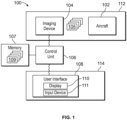
- Figure 1 illustrates a schematic block diagram of a system 100 for inspecting an aircraft 102, according to an example of the present disclosure.
- the system 100 can be used in relation to various types of inspection, such as general visual inspection, lightning strike inspection, hail damage inspection, and/or the like.
- the system 100 can be used during maintenance operations, as well as a manufacturing process.
- the system 100 includes an imaging device 104, such as a camera.
- the camera can be a digital photographic camera.
- the imaging device 104 can be a video camera.
- the imaging device 104 can be an infrared camera.
- the imaging device 104 is configured to acquire images 105 of various portions of the aircraft 102. In at least one example, the imaging device 104 is configured to acquire digital photographs of various exterior surfaces of the aircraft 102. As another example, the imaging device 104 can be configured to acquire digital video of the various surfaces of the aircraft 102.
- the imaging device 104 can be supported on a mobile platform that is configured to maneuver the imaging device 104 around the aircraft.
- the imaging device 104 can be coupled to a mobile cart, such as by one or more moving arms, booms, or the like.
- the imaging device 104 can be coupled to a drone, which is configured to be flown around the aircraft.
- the imaging device 104 can be moved in accordance with a defined path (for example, flight plan defined by an original equipment manufacturer (OEM) or airline associated with the aircraft) to ensure that the inspection is completed in a manner such that certification or other requirements are met.
- a defined path for example, flight plan defined by an original equipment manufacturer (OEM) or airline associated with the aircraft
- the imaging device 104 and the aircraft 102 are at a first location 112. That is, the imaging device 104 is at the location of the aircraft 102.
- the imaging device 104 is located proximate to (such as within a viewing range of the imaging device 104) the aircraft 102 to allow the imaging device 104 to acquire the images 105 of various exterior and/or interior surfaces of the aircraft 102, as described herein.
- image positioning plans for the imaging device 104 establish an image field of view, distance from an object to be imaged, a gimble angle setting, and/or other location and orientation requirements.
- a control unit 106 is in communication with the imaging device 104, such as through one or more wired or wireless connections.
- the control unit 106 can be remotely located from the imaging device 104.
- the control unit 106 is configured to receive the acquired images from the imaging device 104.
- the control unit 106 is also in communication with a user interface 108, such as through one or more wired or wireless connections.
- the user interface 108 includes a display 110, such as an electronic monitor, television, or the like.
- the control unit 106 and the user interface 108 are part of a computer workstation. In at least one other example, the control unit 106 and the user interface 108 can be part of a handheld device.
- the user interface 108 also includes an input device 111, such as one or more of a keyboard, a mouse, a stylus, a touchscreen interface, and/or the like.
- the input device 111 allows a user to retrieve images and data, select and manipulate the images and data, and/or the like.
- the user interface 108 is at a second location 114 that is separate and distinct from the first location 112.
- the first location 112 may not be viewable from the second location 114.
- the first location 112 outside of a gate of an airport, while the second location 114 can be a closed room in which the first location 112 cannot be viewed.
- the first location 112 and the second location 114 can be separated by large distances, such as tens, hundred, or thousands of miles apart.
- the user interface 108 is remotely located from the imaging device 104 and the aircraft 102. That is, the user interface 108 is not at the first location 112, such as the location of the aircraft. Instead, the user interface 108 can be at a central monitoring location, which is remote from the aircraft.
- the control unit 106 can be at the first location 112.
- the imaging device 104 can include the control unit 106.
- the control unit 106 can be at the second location 114.
- the control unit 106 can be at a third location that differs from the first location 112 and the second location 114.
- control unit 106 is also in communication with a memory 107, such as through one or more wired or wireless connections.
- the control unit 106 can include the memory 107.
- the memory 107 stores one or more reference images 109 of portions of the aircraft 102.
- control unit 106 can also store the images 105 acquired by the imaging device 104, such as within the memory 107. In this manner, the acquired images 105 can be used as additional reference images 109 for future inspections. The stored images 105 can be used to track potential damage over time, as well as provide permanent digital records of a condition of the aircraft 102.
- the imaging device 104 acquires the images 105 of various surfaces of the aircraft.
- the control unit 106 receives the images 105, which are then shown on the display 110.
- the inspection of the aircraft 102 is performed at the second location 114, remotely from the first location 112, such as by an individual viewing the images 105 on the display 110.
- the control unit 106 is configured to show the images 105 on the display 110 at the second location 114.
- the images 105 shown in the display 110 at the second location 114 are shown on the display to match human eye capability at the first location 112.
- the control unit 106 automatically performs the inspection without human intervention. For example, the control unit 106 compares the images 105 with the reference images 109 to automatically determine anomalies (for example, differences) therebetween. The control unit 106 then flags the anomalies on the images 105, and outputs an alert to the user interface 108 indicating the anomalies.
- the alert can include one or more of a graphic, text, audio, and/or the like. For example, the control unit 106 can automatically highlight, enclose, circle, indicate through an arrow, and/or the like anomalies within the images 105.
- control unit central processing unit
- CPU central processing unit
- computer computer
- RISC reduced instruction set computers
- ASICs application specific integrated circuits
- the control unit 106 may be or include one or more processors that are configured to control operation, as described herein.
- the control unit 106 is configured to execute a set of instructions that are stored in one or more data storage units or elements (such as one or more memories), in order to process data.
- the control unit 106 may include or be coupled to one or more memories.
- the data storage units may also store data or other information as desired or needed.
- the data storage units may be in the form of an information source or a physical memory element within a processing machine.
- the set of instructions may include various commands that instruct the control unit 106 as a processing machine to perform specific operations such as the methods and processes of the various examples of the subject matter described herein.
- the set of instructions may be in the form of a software program.
- the software may be in various forms such as system software or application software. Further, the software may be in the form of a collection of separate programs, a program subset within a larger program, or a portion of a program.
- the software may also include modular programming in the form of object-oriented programming.
- the processing of input data by the processing machine may be in response to user commands, or in response to results of previous processing, or in response to a request made by another processing machine.
- the diagrams of examples herein may illustrate one or more control or processing units, such as the control unit 106.
- the processing or control units may represent circuits, circuitry, or portions thereof that may be implemented as hardware with associated instructions (e.g., software stored on a tangible and non-transitory computer readable storage medium or a computer readable storage medium, such as a computer hard drive, ROM, RAM, or the like) that perform the operations described herein.
- the hardware may include state machine circuitry hardwired to perform the functions described herein.
- the hardware may include electronic circuits that include and/or are connected to one or more logic-based devices, such as microprocessors, processors, controllers, or the like.
- control unit 106 may represent processing circuitry such as one or more of a field programmable gate array (FPGA), application specific integrated circuit (ASIC), microprocessor(s), and/or the like.
- FPGA field programmable gate array
- ASIC application specific integrated circuit
- microprocessor(s) and/or the like.
- the circuits in various examples may be configured to execute one or more algorithms to perform functions described herein.
- the one or more algorithms may include aspects of examples disclosed herein, whether or not expressly identified in a flowchart or a method.
- the terms "software” and “firmware” are interchangeable, and include any computer program stored in a data storage unit (for example, one or more memories) for execution by a computer, including RAM memory, ROM memory, EPROM memory, EEPROM memory, and non-volatile RAM (NVRAM) memory.
- a data storage unit for example, one or more memories
- NVRAM non-volatile RAM
- the above data storage unit types are exemplary only, and are thus not limiting as to the types of memory usable for storage of a computer program.
- the system 100 is configured to provide a remote, non-instrumented inspection in relation to an exterior and/or interior of the aircraft 102.
- the remote inspection is configured to be equivalent to aircraft maintenance performed by a licensed mechanic/inspector at the aircraft inspection location.
- examples of the present disclosure use the images 105 and specified monitor capability at a location (such as the second location 114) that is remote from the aircraft 102.
- the control unit 106 provides the images 105 of the aircraft 102, acquired by the imaging device 104 at the first location 112, to the display 110 at the second location 114. For example, the control unit 106 shows the images 105 on the display 110.
- control unit 106 calculates optical requirements (for example, monitor size, pixel density, distance from monitor, and the like) of the display 110 to preserve an optical resolution needed to match human eye inspection performance. Examples of the present disclosure ensure equivalent results between the inspection performed remotely and at the inspection location. In general, the systems and methods described herein allow for remote visual inspection of images of surfaces of the aircraft 102.
- the remote inspection systems and methods described herein substantially reduce inspection time (such as by at least 50%).
- the systems and methods also (a) allow for flexible maintenance planning activity that identifies surface anomalies early in the process, (b) reduce airline costs, and (c) increase safety (for example, the individual does not need to move on and around the aircraft 102).
- Known aircraft inspection processes are governed by regulation and approved practices.
- An aircraft manufacturer mandates approved maintenance practices to ensure continued safe operation.
- the systems and methods described herein ensure equivalent outcomes to the inspection performed at the site.
- Remote aircraft inspections utilize unique processes and tools for large area inspections, and eliminate or otherwise reduce the need for access infrastructure such as lifts and stanchions, thereby reducing exposure to potential safety events.
- the systems and methods analyze the following: 1) human eye acuity, 2) distance from aircraft, 3) human eye resolution, and 4) monitor characteristics.
- Figure 2 illustrates a simplified diagram of a mobile platform 120 having the imaging device 104, according to an example of the present disclosure.
- the imaging device 104 is supported on the mobile platform 120, such as a moveable cart configured to maneuver the imaging device 104 around an aircraft.
- the mobile platform 120 includes a base 121 having wheels 122.
- One or more moveable arms 124 moveable couple the imaging device 104 to the base 121.
- FIG 3 illustrates a simplified diagram of a mobile platform 120 having the imaging device 104, according to an example of the present disclosure.
- the mobile platform 120 can be or otherwise include a drone having an airframe 126 and a propulsion system 128, such as one or more propellers.
- the drone is configured to be flown around an aircraft.
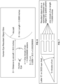
- Figure 4 illustrates a simplified description of human eye capability.
- the control unit 106 can first establish the human eye's capability in order to replicate the human eye examination of the aircraft 102 using a remote computer station, such as the user interface 108.
- the human eye is capable of clearly seeing objects of a particular size from a specified distance. Measurement of this ability is defined as acuity.
- a visual acuity test is an eye examination that measures an individual's eyes ability to read or see small details determining the sharpness and clarity of vision.
- the capabilities of the eye determine the ability to see non-conformances on the objects surface such as scratches, gouges, cracks, and the like.
- the control unit 106 can assume 20/20 vision, which is a typical measure of normal vision either corrected or uncorrected. 20/20 vision is defined as an individual's ability to see an object at 20 feet away resolved to 1 arc minute the same as an average individual can see on an eye chart.
- Figure 5 illustrates a simplified view of an individual 130 separated from a surface 132 of the aircraft 102 by a distance 134.
- Aircraft inspections are typically conducted at specified distances from the aircraft 102, depending on the type of inspection being conducted. For example, a general visual inspection is defined by industry guidance to be conducted within touching distance.
- the control unit 106 can use 30.5 inches as an average of typical men's and women's arms reach indicating the distance one would be from the aircraft 102 being inspected if a general visual inspection was being conducted.
- the distance 134 can be less than 30.5 inches (such as 20-30 inches), or greater than 30.5 inches (such as 31-45 inches).
- Figure 6 illustrates a simplified description of human eye resultant object size.
- Figure 7 illustrates a letter E on an eye chart.
- the control unit 106 calculates a resulting arc length (S) when Theta is 1 minute of arc and D is 30.5 inches away from the object.
- S resulting arc length
- the resultant object size or space/gap between two edges of a spatial pattern that can be seen with 20/20 vision is 0.0089 inches, which represents the size of the object that can be resolved by the human eye.
- Figure 8 illustrates a simplified description of human eye resolution in mega-pixels.
- the area an individual is capable of observing when standing within arms' reach from the aircraft is 48 inches up: down and 72 inches left:right, which is referred to as a Field of View (FOV).
- FOV Field of View
- the FOV is case is defined to be a 6 foot by 4 foot rectangle defining the bounds of the individual's capability to see in all directions from an inspection location.
- the size of the resultant object size that can be resolved by the human eye at 30.5 inches from the object is 0.0089 inches.
- control unit 106 divides the resultant object size (.0089") by the 6 foot x 4 foot FOV, thereby giving the number of pixels that would fit in the 6 foot x 4 foot space. This calculation results in 8089 pixels x 5393 pixels for a total of 43,623,977 pixels or about 44 mega-pixels.
- Figure 9 illustrates a simplified description of observing a 44 mexapixel (MP) image on a monitor of fixed resolution.
- resolution of an exemplary display 110 is a measure of how many pixels the display 110 can show. Higher resolution results in sharper images.
- the monitor resolution is to provide 44 MP.
- the control unit 106 can use a 1:1 representation of 44 MP to maintain the human visual experience.
- the control unit 106 removes 35.7 MP from the image 105 creating a lower resolution image. Viewing the image on the 8.3 MP monitor represents approximately 1/5 of the pixel data. To observe all 44 MP of the image on an 8.3 MP display 110, the control unit 106 partitions the image 105 into 5.3 MP parts 105a, 105b, 105c, 105d, and 105e on the display 110.
- a smaller monitor at a specific resolution can provide sharper images than a larger monitor at the same resolution.
- a sharper image on a smaller monitor may present difficulties in observing details due to monitor size.
- Figure 10 illustrates a simplified description of an observing distance d from a display 110.
- the remote inspection is conducted at a computer station (for example, the user interface 108, shown in Figure 1 ) having the display 110 (such as an electronic monitor) positioned at a specified position from the observer's eye.
- the monitor-to-eye distance ensures one pixel of screen resolution to be seen at one minute of arc by the observer.
- the distance d ensures that the monitor-to-eye distance allows 1 pixel of screen resolution to be seen at 1 minute of arc by the observer.
- the display 110 is a 4K monitor, which is 21 inches wide (3840 pixel), 12 inches in height (2160 pixel), and 8,217,600 Pixel (8.3 MP).
- d 19.03785 inches observing distance from the display 110.
- Figure 11 illustrates an image 105 of a portion of an aircraft, according to an example of the present disclosure.
- Figure 12 illustrates the image 105 of Figure 11 in partitions or parts A, B, C, D, E, and F, according to an example of the present disclosure.
- the control unit 106 partitions the image 105 for the inspection at the display 110.
- the control unit 106 partitions the image 105 into separate parts A-F.
- the control unit 106 determines the size, shape, and number of parts A-F using various factors including, but not limited to, inspection monitor specifications, size/resolution of the acquired image, type of inspection to be performed, etc.
- the control unit 106 divides the image 105 (acquired by the imaging device 104 at the location of the aircraft 102) of 44 MP into six 7.3 MP parts A-F, as shown in Figure 12 .
- the images 105 are shown on the display 110, and the individual inspects the images 105 for anomalies (such as damage, defects, and the like) on the exterior of the aircraft 102.
- the control unit 106 compares the images 105 in relation to the reference images 109 (such as stored images of the aircraft, as manufactured, and/or from previous inspections) within the memory 107. Based on the comparison, the control unit 106 can automatically flag differences between the current images 105 and the reference images 109. As another example, the control unit 106 can automatically determine the anomalies, such as through artificial intelligence, machine learning, and/or the like. In at least one example, the control unit 106 can also tag the images with relevant images numbers to provide a unique image identifier that supports other trend analysis processes.
- the sequence in which the parts A-F are presented on the display 110 can be predefined or determined based on artificial intelligence or machine learning. For example, parts with identified or potential defects can be shown first.
- the images can be checked by the control unit 106 for color, contrast, and resolution.
- the control unit 106 can also determine and indicate an image overlap percentage.
- the images can be configured to overlap one another, which can provide different points of view and contrasts, and can provide easier identification of anomalies.
- control unit 106 can also register aircraft surface coordinates in relation to the images 105. As such, the control unit 106 can provide identification of where the images 105 are in relation to the aircraft 102.
- control unit 106 can also overlay frame and rib station, stringer, longeron, wing spar, and the like locations on the images.
- control unit 106 is configured to provide an inspection image coverage progression.
- control unit 106 is configured to identify defective areas of interest, categorize, and classify defects, evaluate defect size and depth, perform non-contact, non-destructive testing, and/or provide reports.
- the control unit 106 can analyze images 105 from multiple inspections using data analytics and trend analysis to identify anomalies in the images.
- defect or damage information can be translated by the control unit 106 to a three-dimensional model of the aircraft 102 that documents dent and buckle information (for example, damage type, size, location, etc.).
- all or part of the systems and methods described herein may be or otherwise include an artificial intelligence (AI) or machine-learning system that can automatically perform operations of the methods described herein.
- the control unit 106 can be an artificial intelligence or machine learning system.
- AI artificial intelligence
- these types of systems may be trained from outside information and/or self-trained to repeatedly improve the accuracy with how data is analyzed to automatically detect anomalies within the images 105. Over time, these systems can improve by determining such information with increasing accuracy and speed, thereby significantly reducing the likelihood of any potential errors.
- the AI or machine-learning systems can learn and determine image partition parameters, and automatically detect anomalies within the images 105, defect areas, and/or the like.
- the AI or machine-learning systems described herein may include technologies enabled by adaptive predictive power and that exhibit at least some degree of autonomous learning to automate and/or enhance pattern detection (for example, recognizing irregularities or regularities in data), customization (for example, generating or modifying rules to optimize record matching), and/or the like.
- the systems may be trained and re-trained using feedback from one or more prior analyses of the data, ensemble data, and/or other such data. Based on this feedback, the systems may be trained by adjusting one or more parameters, weights, rules, criteria, or the like, used in the analysis of the same. This process can be performed using the data and ensemble data instead of training data, and may be repeated many times to repeatedly improve the determination and location of various features within the images 105.
- the training minimizes conflicts and interference by performing an iterative training algorithm, in which the systems are retrained with an updated set of data, and based on the feedback examined prior to the most recent training of the systems.
- This provides a robust analysis model that can better determine locations, features, structures, and/or the like in a cost effective and efficient manner.
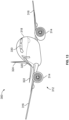
- Figure 13 illustrates a perspective front view of an aircraft 300, according to an example of the present disclosure.
- the aircraft 300 is an example of the aircraft 102 shown in Figure 1 .
- the aircraft 300 includes a propulsion system 312 that includes engines 314, for example.
- the propulsion system 312 may include more engines 314 than shown.
- the engines 314 are carried by wings 316 of the aircraft 300.
- the engines 314 may be carried by a fuselage 318 and/or an empennage 320.
- the empennage 320 may also support horizontal stabilizers 322 and a vertical stabilizer 324.
- the fuselage 318 of the aircraft 300 defines an internal cabin 330.
- Figure 13 shows an example of an aircraft 300.
- aircraft 300 can be sized, shaped, and configured differently than shown in Figure 13 .
- examples of the present disclosure can be used with various other types of vehicles, such as automobiles, buses, trains, watercraft, spacecraft, or the like.
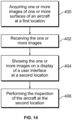
- Figure 14 illustrates a flow chart of a method, according to an example of the present disclosure.
- the method is for an inspection of the aircraft 102, which is at the first location 112.
- the method includes acquiring, at 400, by the imaging device 104, one or more images 105 of one of or more surfaces of the aircraft 102 at the first location 112.
- the method further includes receiving, at 402, by the control unit 106 in communication with the imaging device 104, the one or more images 105.
- the method also includes showing, at 404, by the control unit 106, the one or more images 105 on the display 110 of the user interface 108, which is at the second location 114 that differs from the first location 112.
- the method also includes performing, at 406, by the showing 404, the inspection of the aircraft 102 at the second location 114.
- the method can also include creating and submitting a report regarding the inspection.
- the method also includes modifying, by the control unit 106, the one or more images 105 based on at least one characteristic of the display 110.
- the method also includes calculating, by the control unit 106, optical requirements of the display 110 to preserve an optical resolution that matches human eye inspection performance of the aircraft 102.
- the method also includes modeling, by the control unit 106, human vision performance by applying calculations of human eye resolving power to establish a baseline for replicating capabilities on the display 110.
- the showing 404 includes partitioning, by the control unit 106, the one or more images 105 into parts.
- the method can also include storing, by the control unit 106, the one or more images 105 in the memory 107.
- the method also includes comparing, by the control unit 106, the one or more images 105 with one or more reference images 109 of the aircraft 102, and automatically detecting, by the control unit 106, one or more anomalies through the comparing.
- the method includes automatically determining, by the control unit 106, one or more anomalies in the one or more images 105 through artificial intelligence or machine learning.
- examples of the present disclosure provide improved systems and methods for inspecting aircraft.
- a structure, limitation, or element that is "configured to” perform a task or operation is particularly structurally formed, constructed, or adapted in a manner corresponding to the task or operation.
- an object that is merely capable of being modified to perform the task or operation is not “configured to” perform the task or operation as used herein.
Landscapes
- Engineering & Computer Science (AREA)
- Manufacturing & Machinery (AREA)
- Transportation (AREA)
- Aviation & Aerospace Engineering (AREA)
- Physics & Mathematics (AREA)
- Health & Medical Sciences (AREA)
- Life Sciences & Earth Sciences (AREA)
- Chemical & Material Sciences (AREA)
- Analytical Chemistry (AREA)
- Biochemistry (AREA)
- General Health & Medical Sciences (AREA)
- General Physics & Mathematics (AREA)
- Immunology (AREA)
- Pathology (AREA)
- Investigating Materials By The Use Of Optical Means Adapted For Particular Applications (AREA)
- Image Analysis (AREA)
Abstract
Description
- This application relates to and claims priority benefits from
U.S. Provisional Patent Application No. 63/502,929, filed May 18, 2023 - Examples of the present disclosure generally relate to systems and methods for remotely inspecting aircraft.
- Aircraft are used to transport passengers and cargo between various locations. Numerous aircraft depart from and arrive at a typical airport every day.
- Aircraft are manually inspected before and after flights. For example, an individual views various portions of an aircraft for evidence of damage, such as caused by other objects, hail, lightning, and/or the like. Manual inspections generally require use of lifts, which risk potential falls, and can potentially cause damage to the aircraft, such as through accidental lift contact. Further, the process of such inspections is time and labor intensive. For example, one or more individuals operate the lift, as well as adroitly maneuver support equipment to access various areas of an aircraft. Also, manual documentation of inspection results typically produces non-digital information that may not be readily accessible.
- A need exists for an improved system and method for inspecting aircraft. With that need in mind, certain examples of the present disclosure provide a system configured for an inspection of an aircraft at a first location. The system includes an imaging device configured to acquire one or more images of one of or more surfaces of the aircraft at the first location. A control unit is in communication with the imaging device. The control unit is configured to receive the one or more images. A user interface is in communication with the control unit. The user interface is at a second location that differs from the first location. The user interface includes a display. The control unit is configured to show the one or more images on the display. The inspection is performed at the second location.
- The inspection can include one or more of a general visual inspection of the aircraft, a lightning strike inspection of the aircraft, or a hail damage inspection of the aircraft.
- In at least one example, the control unit is configured to modify the one or more images based on at least one characteristic of the display.
- In at least one example, the control unit is configured to calculate optical requirements of the display to preserve an optical resolution that matches human eye inspection performance of the aircraft.
- In at least one example, the control unit is configured to model human vision performance by applying calculations of human eye resolving power to establish a baseline for replicating capabilities on the display.
- In at least one example, the control unit is configured to partition the one or more images into parts shown on the display.
- The control unit can be further configured to store the one or more images in a memory.
- In at least one example, a mobile cart includes the imaging device. As another example, a drone includes the imaging device.
- In at least one example, the control unit is configured to compare the one or more images with one or more reference images of the aircraft to automatically detect one or more anomalies.
- In at least one example, the control unit is configured to automatically determine one or more anomalies in the one or more images through artificial intelligence or machine learning.
- Certain examples of the present disclosure provide a method for an inspection of an aircraft at a first location. The method includes acquiring, by an imaging device, one or more images of one of or more surfaces of the aircraft at the first location; receiving, by a control unit in communication with the imaging device, the one or more images; showing, by the control unit, the one or more images on a display of a user interface at a second location that differs from the first location; and performing, by said showing, the inspection of the aircraft at the second location.
- Certain examples of the present disclosure provide a non-transitory computer-readable storage medium comprising executable instructions that, in response to execution, cause one or more control units comprising a processor, to perform operations including receiving one or more images of one or portions of an aircraft at a first location from an imaging device; and showing the one or more images on a display of a user interface at a second location that differs from the first location to allow performance of the inspection at the second location.
-
-
Figure 1 illustrates a schematic block diagram of a system for inspecting an aircraft, according to an example of the present disclosure. -
Figure 2 illustrates a simplified diagram of a mobile platform having an imaging device, according to an example of the present disclosure. -
Figure 3 illustrates a simplified diagram of a mobile platform having an imaging device, according to an example of the present disclosure. -
Figure 4 illustrates a simplified description of human eye capability. -
Figure 5 illustrates a simplified view of an individual separated from a surface of an aircraft by a distance. -
Figure 6 illustrates a simplified description of human eye resultant object size. -
Figure 7 illustrates a letter E on an eye chart. -
Figure 8 illustrates a simplified description of human eye resolution in mega-pixels. -
Figure 9 illustrates a simplified description of observing a 44 mexapixel image on a monitor of fixed resolution. -
Figure 10 illustrates a simplified description of an observing distance from a display. -
Figure 11 illustrates an image of a portion of an aircraft, according to an example of the present disclosure. -
Figure 12 illustrates the image ofFigure 11 in partitions, according to an example of the present disclosure. -
Figure 13 illustrates a perspective front view of an aircraft, according to an example of the present disclosure. -
Figure 14 illustrates a flow chart of a method, according to an example of the present disclosure. - The foregoing summary, as well as the following detailed description of certain examples will be better understood when read in conjunction with the appended drawings. As used herein, an element or step recited in the singular and preceded by the word "a" or "an" should be understood as not necessarily excluding the plural of the elements or steps. Further, references to "one example" are not intended to be interpreted as excluding the existence of additional examples that also incorporate the recited features. Moreover, unless explicitly stated to the contrary, examples "comprising" or "having" an element or a plurality of elements having a particular condition can include additional elements not having that condition.
- Examples of the present disclosure provide systems and methods for remotely inspecting aircraft. The systems and methods may be used with various types of aircraft inspections, such as general visual inspections, lightning strike inspections, hail damage inspections, and/or the like. The systems and methods provide remote inspections that reduce overall inspection time, reduce the potential of injury to individuals, as well as reduce the potential of damage to an aircraft.
- The systems and methods provide image-based, remote inspections. The images may be stored for future reference, and can be used to track potential damage over time, as well as provide permanent digital records of aircraft condition.
- In at least one example, the systems and methods are configured to determine and translate human eye capabilities to digital information to be viewed at a remote work station. Image capture parameters and monitor technical specifications can be used in a process that replicates the experience at the aircraft while positioned in a remote location. Transfer of image information can be processed through a cloud system by inspectors anywhere in the world.
- Examples of the present disclosure provide an equivalent inspection experience that satisfies certified aircraft maintenance requirements. The systems and methods can be configured to determine damage type, such as through stored reference images, artificial intelligence, and/or machine learning.
- In at least one example, a control unit performs an image processing algorithm, which can also provide image overlap percentage, inspection image progression, depth and size evaluation, and the like. In at least one example, the control unit is configured to model human vision performance, such as by applying calculations of the human eye resolving power that establishes a baseline for replicating capabilities at a remote work site. Remote site hardware and system specifications for monitor capabilities are used in processing logic by the control unit. The results of the modeling create an image partition scheme that utilize the capabilities of a monitor and the input of the aircraft image associated with the human eye model at the work site.
- Examples of the present disclosure provide systems and methods for inspecting an aircraft. The systems and methods include an imaging device configured to acquire one or more images of one of or more surfaces of the aircraft. A control unit is in communication with the imaging device. The control unit is configured to receive the one or more images. A user interface is in communication with the control unit. The user interface includes a display. The control unit is configured to show the one or more images (such as processed image(s)) on the display. In at least one example, the imaging device is at a location of the aircraft, and the user interface is remote from the location of the aircraft. In at least one example, the control unit is configured to modify the one or more images based on at least one characteristic of the display.
-
Figure 1 illustrates a schematic block diagram of asystem 100 for inspecting anaircraft 102, according to an example of the present disclosure. Thesystem 100 can be used in relation to various types of inspection, such as general visual inspection, lightning strike inspection, hail damage inspection, and/or the like. Thesystem 100 can be used during maintenance operations, as well as a manufacturing process. Thesystem 100 includes animaging device 104, such as a camera. The camera can be a digital photographic camera. As another example, theimaging device 104 can be a video camera. As another example, theimaging device 104 can be an infrared camera. - The
imaging device 104 is configured to acquireimages 105 of various portions of theaircraft 102. In at least one example, theimaging device 104 is configured to acquire digital photographs of various exterior surfaces of theaircraft 102. As another example, theimaging device 104 can be configured to acquire digital video of the various surfaces of theaircraft 102. - In at least one example, the
imaging device 104 can be supported on a mobile platform that is configured to maneuver theimaging device 104 around the aircraft. As an example, theimaging device 104 can be coupled to a mobile cart, such as by one or more moving arms, booms, or the like. As another example, theimaging device 104 can be coupled to a drone, which is configured to be flown around the aircraft. Theimaging device 104 can be moved in accordance with a defined path (for example, flight plan defined by an original equipment manufacturer (OEM) or airline associated with the aircraft) to ensure that the inspection is completed in a manner such that certification or other requirements are met. - The
imaging device 104 and theaircraft 102 are at afirst location 112. That is, theimaging device 104 is at the location of theaircraft 102. Theimaging device 104 is located proximate to (such as within a viewing range of the imaging device 104) theaircraft 102 to allow theimaging device 104 to acquire theimages 105 of various exterior and/or interior surfaces of theaircraft 102, as described herein. In at least one example, image positioning plans for theimaging device 104 establish an image field of view, distance from an object to be imaged, a gimble angle setting, and/or other location and orientation requirements. - A
control unit 106 is in communication with theimaging device 104, such as through one or more wired or wireless connections. Thecontrol unit 106 can be remotely located from theimaging device 104. Thecontrol unit 106 is configured to receive the acquired images from theimaging device 104. - The
control unit 106 is also in communication with auser interface 108, such as through one or more wired or wireless connections. Theuser interface 108 includes adisplay 110, such as an electronic monitor, television, or the like. In at least one example, thecontrol unit 106 and theuser interface 108 are part of a computer workstation. In at least one other example, thecontrol unit 106 and theuser interface 108 can be part of a handheld device. Theuser interface 108 also includes aninput device 111, such as one or more of a keyboard, a mouse, a stylus, a touchscreen interface, and/or the like. Theinput device 111 allows a user to retrieve images and data, select and manipulate the images and data, and/or the like. - The
user interface 108 is at asecond location 114 that is separate and distinct from thefirst location 112. Thefirst location 112 may not be viewable from thesecond location 114. As an example, thefirst location 112 outside of a gate of an airport, while thesecond location 114 can be a closed room in which thefirst location 112 cannot be viewed. As another example, thefirst location 112 and thesecond location 114 can be separated by large distances, such as tens, hundred, or thousands of miles apart. Theuser interface 108 is remotely located from theimaging device 104 and theaircraft 102. That is, theuser interface 108 is not at thefirst location 112, such as the location of the aircraft. Instead, theuser interface 108 can be at a central monitoring location, which is remote from the aircraft. - The
control unit 106 can be at thefirst location 112. For example, theimaging device 104 can include thecontrol unit 106. As another example, thecontrol unit 106 can be at thesecond location 114. As another example, thecontrol unit 106 can be at a third location that differs from thefirst location 112 and thesecond location 114. - In at least one example, the
control unit 106 is also in communication with amemory 107, such as through one or more wired or wireless connections. Thecontrol unit 106 can include thememory 107. Thememory 107 stores one ormore reference images 109 of portions of theaircraft 102. - In at least one example, the
control unit 106 can also store theimages 105 acquired by theimaging device 104, such as within thememory 107. In this manner, the acquiredimages 105 can be used asadditional reference images 109 for future inspections. The storedimages 105 can be used to track potential damage over time, as well as provide permanent digital records of a condition of theaircraft 102. - In operation, the
imaging device 104 acquires theimages 105 of various surfaces of the aircraft. 102 Thecontrol unit 106 receives theimages 105, which are then shown on thedisplay 110. As such, the inspection of theaircraft 102 is performed at thesecond location 114, remotely from thefirst location 112, such as by an individual viewing theimages 105 on thedisplay 110. - The
control unit 106 is configured to show theimages 105 on thedisplay 110 at thesecond location 114. Theimages 105 shown in thedisplay 110 at thesecond location 114 are shown on the display to match human eye capability at thefirst location 112. - In at least one example, the
control unit 106 automatically performs the inspection without human intervention. For example, thecontrol unit 106 compares theimages 105 with thereference images 109 to automatically determine anomalies (for example, differences) therebetween. Thecontrol unit 106 then flags the anomalies on theimages 105, and outputs an alert to theuser interface 108 indicating the anomalies. The alert can include one or more of a graphic, text, audio, and/or the like. For example, thecontrol unit 106 can automatically highlight, enclose, circle, indicate through an arrow, and/or the like anomalies within theimages 105. - As used herein, the term "control unit," "central processing unit," "CPU," "computer," or the like may include any processor-based or microprocessor-based system including systems using microcontrollers, reduced instruction set computers (RISC), application specific integrated circuits (ASICs), logic circuits, and any other circuit or processor including hardware, software, or a combination thereof capable of executing the functions described herein. Such are exemplary only, and are thus not intended to limit in any way the definition and/or meaning of such terms. For example, the
control unit 106 may be or include one or more processors that are configured to control operation, as described herein. - The
control unit 106 is configured to execute a set of instructions that are stored in one or more data storage units or elements (such as one or more memories), in order to process data. For example, thecontrol unit 106 may include or be coupled to one or more memories. The data storage units may also store data or other information as desired or needed. The data storage units may be in the form of an information source or a physical memory element within a processing machine. - The set of instructions may include various commands that instruct the
control unit 106 as a processing machine to perform specific operations such as the methods and processes of the various examples of the subject matter described herein. The set of instructions may be in the form of a software program. The software may be in various forms such as system software or application software. Further, the software may be in the form of a collection of separate programs, a program subset within a larger program, or a portion of a program. The software may also include modular programming in the form of object-oriented programming. The processing of input data by the processing machine may be in response to user commands, or in response to results of previous processing, or in response to a request made by another processing machine. - The diagrams of examples herein may illustrate one or more control or processing units, such as the
control unit 106. It is to be understood that the processing or control units may represent circuits, circuitry, or portions thereof that may be implemented as hardware with associated instructions (e.g., software stored on a tangible and non-transitory computer readable storage medium or a computer readable storage medium, such as a computer hard drive, ROM, RAM, or the like) that perform the operations described herein. The hardware may include state machine circuitry hardwired to perform the functions described herein. Optionally, the hardware may include electronic circuits that include and/or are connected to one or more logic-based devices, such as microprocessors, processors, controllers, or the like. Optionally, thecontrol unit 106 may represent processing circuitry such as one or more of a field programmable gate array (FPGA), application specific integrated circuit (ASIC), microprocessor(s), and/or the like. The circuits in various examples may be configured to execute one or more algorithms to perform functions described herein. The one or more algorithms may include aspects of examples disclosed herein, whether or not expressly identified in a flowchart or a method. - As used herein, the terms "software" and "firmware" are interchangeable, and include any computer program stored in a data storage unit (for example, one or more memories) for execution by a computer, including RAM memory, ROM memory, EPROM memory, EEPROM memory, and non-volatile RAM (NVRAM) memory. The above data storage unit types are exemplary only, and are thus not limiting as to the types of memory usable for storage of a computer program.
- The
system 100 is configured to provide a remote, non-instrumented inspection in relation to an exterior and/or interior of theaircraft 102. The remote inspection is configured to be equivalent to aircraft maintenance performed by a licensed mechanic/inspector at the aircraft inspection location. Using a typical human vision rating standard such as 20/20 vision for completing the inspection by a human at the inspection location, examples of the present disclosure use theimages 105 and specified monitor capability at a location (such as the second location 114) that is remote from theaircraft 102. Thecontrol unit 106 provides theimages 105 of theaircraft 102, acquired by theimaging device 104 at thefirst location 112, to thedisplay 110 at thesecond location 114. For example, thecontrol unit 106 shows theimages 105 on thedisplay 110. - In at least one example, the
control unit 106 calculates optical requirements (for example, monitor size, pixel density, distance from monitor, and the like) of thedisplay 110 to preserve an optical resolution needed to match human eye inspection performance. Examples of the present disclosure ensure equivalent results between the inspection performed remotely and at the inspection location. In general, the systems and methods described herein allow for remote visual inspection of images of surfaces of theaircraft 102. - It has been found that the remote inspection systems and methods described herein substantially reduce inspection time (such as by at least 50%). The systems and methods also (a) allow for flexible maintenance planning activity that identifies surface anomalies early in the process, (b) reduce airline costs, and (c) increase safety (for example, the individual does not need to move on and around the aircraft 102).
- Known aircraft inspection processes are governed by regulation and approved practices. An aircraft manufacturer mandates approved maintenance practices to ensure continued safe operation. In order to perform a remote inspection that is equivalent to current practices having a mechanic positioned at the aircraft, the systems and methods described herein ensure equivalent outcomes to the inspection performed at the site. Remote aircraft inspections utilize unique processes and tools for large area inspections, and eliminate or otherwise reduce the need for access infrastructure such as lifts and stanchions, thereby reducing exposure to potential safety events. As described herein, the systems and methods analyze the following: 1) human eye acuity, 2) distance from aircraft, 3) human eye resolution, and 4) monitor characteristics.
-
Figure 2 illustrates a simplified diagram of amobile platform 120 having theimaging device 104, according to an example of the present disclosure. Theimaging device 104 is supported on themobile platform 120, such as a moveable cart configured to maneuver theimaging device 104 around an aircraft. For example, themobile platform 120 includes a base 121 havingwheels 122. One or moremoveable arms 124 moveable couple theimaging device 104 to thebase 121. -
Figure 3 illustrates a simplified diagram of amobile platform 120 having theimaging device 104, according to an example of the present disclosure. Themobile platform 120 can be or otherwise include a drone having anairframe 126 and apropulsion system 128, such as one or more propellers. The drone is configured to be flown around an aircraft. -
Figure 4 illustrates a simplified description of human eye capability. Referring toFigures 1-4 , in at least one example, thecontrol unit 106 can first establish the human eye's capability in order to replicate the human eye examination of theaircraft 102 using a remote computer station, such as theuser interface 108. The human eye is capable of clearly seeing objects of a particular size from a specified distance. Measurement of this ability is defined as acuity. A visual acuity test is an eye examination that measures an individual's eyes ability to read or see small details determining the sharpness and clarity of vision. In order to conduct an examination of an object such as one or more portions of theaircraft 102 at thefirst location 112, the capabilities of the eye determine the ability to see non-conformances on the objects surface such as scratches, gouges, cracks, and the like. Though different technicians have varied visual acuity, thecontrol unit 106 can assume 20/20 vision, which is a typical measure of normal vision either corrected or uncorrected. 20/20 vision is defined as an individual's ability to see an object at 20 feet away resolved to 1 arc minute the same as an average individual can see on an eye chart. -
Figure 5 illustrates a simplified view of an individual 130 separated from asurface 132 of theaircraft 102 by adistance 134. Aircraft inspections are typically conducted at specified distances from theaircraft 102, depending on the type of inspection being conducted. For example, a general visual inspection is defined by industry guidance to be conducted within touching distance. Referring toFigures 1-5 , in at least one nonlimiting example, thecontrol unit 106 can use 30.5 inches as an average of typical men's and women's arms reach indicating the distance one would be from theaircraft 102 being inspected if a general visual inspection was being conducted. Optionally, thedistance 134 can be less than 30.5 inches (such as 20-30 inches), or greater than 30.5 inches (such as 31-45 inches). -
Figure 6 illustrates a simplified description of human eye resultant object size.Figure 7 illustrates a letter E on an eye chart. As shown and described with respect toFigures 6 and 7 , the ability of a human conducting an inspection at 30.5 inches away from an object can be calculated. Referring toFigures 1-7 , in at least one example, thecontrol unit 106 calculates a resulting arc length (S) when Theta is 1 minute of arc and D is 30.5 inches away from the object. The resultant object size or space/gap between two edges of a spatial pattern that can be seen with 20/20 vision is 0.0089 inches, which represents the size of the object that can be resolved by the human eye. -
Figure 8 illustrates a simplified description of human eye resolution in mega-pixels. As shown and described inFigure 8 , the area an individual is capable of observing when standing within arms' reach from the aircraft is 48 inches up: down and 72 inches left:right, which is referred to as a Field of View (FOV). In this case, the FOV is case is defined to be a 6 foot by 4 foot rectangle defining the bounds of the individual's capability to see in all directions from an inspection location. As described, the size of the resultant object size that can be resolved by the human eye at 30.5 inches from the object is 0.0089 inches. Referring toFigures 1-8 , to find the human eye resolution to cover a 6 foot x 4 foot area thecontrol unit 106 divides the resultant object size (.0089") by the 6 foot x 4 foot FOV, thereby giving the number of pixels that would fit in the 6 foot x 4 foot space. This calculation results in 8089 pixels x 5393 pixels for a total of 43,623,977 pixels or about 44 mega-pixels. -
Figure 9 illustrates a simplified description of observing a 44 mexapixel (MP) image on a monitor of fixed resolution. As shown and described inFigure 9 , resolution of an exemplary display 110 (such as a monitor) is a measure of how many pixels thedisplay 110 can show. Higher resolution results in sharper images. In the case of a human eye at 30.5 inches away from an object that covers a field of view of 48 inches x 72 inches, the monitor resolution is to provide 44 MP. Thus, thecontrol unit 106 can use a 1:1 representation of 44 MP to maintain the human visual experience. - As an example, to view the full 44 MP image on an 8.3 MP monitor (3840 x 2160 pixels), also known as 4K resolution, the
control unit 106 removes 35.7 MP from theimage 105 creating a lower resolution image. Viewing the image on the 8.3 MP monitor represents approximately 1/5 of the pixel data. To observe all 44 MP of the image on an 8.3MP display 110, thecontrol unit 106 partitions theimage 105 into 5.3MP parts display 110. - Optionally, a smaller monitor at a specific resolution can provide sharper images than a larger monitor at the same resolution. However, a sharper image on a smaller monitor may present difficulties in observing details due to monitor size.
-
Figure 10 illustrates a simplified description of an observing distance d from adisplay 110. As shown and described with respect toFigure 10 , the remote inspection is conducted at a computer station (for example, theuser interface 108, shown inFigure 1 ) having the display 110 (such as an electronic monitor) positioned at a specified position from the observer's eye. The monitor-to-eye distance ensures one pixel of screen resolution to be seen at one minute of arc by the observer. The distance d ensures that the monitor-to-eye distance allows 1 pixel of screen resolution to be seen at 1 minute of arc by the observer. As an example, thedisplay 110 is a 4K monitor, which is 21 inches wide (3840 pixel), 12 inches in height (2160 pixel), and 8,217,600 Pixel (8.3 MP). The monitor area = 21 inches x 12 inches = 252 square inches. The area of one pixel is 252 sq inches/ 8,217,600 pixel = 3.06681E-05 square inches.

display 110. -
Figure 11 illustrates animage 105 of a portion of an aircraft, according to an example of the present disclosure.Figure 12 illustrates theimage 105 ofFigure 11 in partitions or parts A, B, C, D, E, and F, according to an example of the present disclosure. Referring toFigures 1-12 , in order to present an individual animage 105 at thedisplay 110 as it would be seen at the location of theaircraft 102, thecontrol unit 106 partitions theimage 105 for the inspection at thedisplay 110. For example, thecontrol unit 106 partitions theimage 105 into separate parts A-F. Thecontrol unit 106 determines the size, shape, and number of parts A-F using various factors including, but not limited to, inspection monitor specifications, size/resolution of the acquired image, type of inspection to be performed, etc. As an example, based on human eye resolution, thecontrol unit 106 divides the image 105 (acquired by theimaging device 104 at the location of the aircraft 102) of 44 MP into six 7.3 MP parts A-F, as shown inFigure 12 . - In at least one example, the
images 105 are shown on thedisplay 110, and the individual inspects theimages 105 for anomalies (such as damage, defects, and the like) on the exterior of theaircraft 102. Optionally, or additionally, in at least one example, thecontrol unit 106 compares theimages 105 in relation to the reference images 109 (such as stored images of the aircraft, as manufactured, and/or from previous inspections) within thememory 107. Based on the comparison, thecontrol unit 106 can automatically flag differences between thecurrent images 105 and thereference images 109. As another example, thecontrol unit 106 can automatically determine the anomalies, such as through artificial intelligence, machine learning, and/or the like. In at least one example, thecontrol unit 106 can also tag the images with relevant images numbers to provide a unique image identifier that supports other trend analysis processes. - In at least one example, the sequence in which the parts A-F are presented on the
display 110 can be predefined or determined based on artificial intelligence or machine learning. For example, parts with identified or potential defects can be shown first. - The images can be checked by the
control unit 106 for color, contrast, and resolution. Thecontrol unit 106 can also determine and indicate an image overlap percentage. The images can be configured to overlap one another, which can provide different points of view and contrasts, and can provide easier identification of anomalies. - In at least one example, the
control unit 106 can also register aircraft surface coordinates in relation to theimages 105. As such, thecontrol unit 106 can provide identification of where theimages 105 are in relation to theaircraft 102. - In at least one example, the
control unit 106 can also overlay frame and rib station, stringer, longeron, wing spar, and the like locations on the images. - In at least one example, the
control unit 106 is configured to provide an inspection image coverage progression. - In at least one example, the
control unit 106 is configured to identify defective areas of interest, categorize, and classify defects, evaluate defect size and depth, perform non-contact, non-destructive testing, and/or provide reports. Thecontrol unit 106 can analyzeimages 105 from multiple inspections using data analytics and trend analysis to identify anomalies in the images. In at least one example, defect or damage information can be translated by thecontrol unit 106 to a three-dimensional model of theaircraft 102 that documents dent and buckle information (for example, damage type, size, location, etc.). - In at least one example, all or part of the systems and methods described herein may be or otherwise include an artificial intelligence (AI) or machine-learning system that can automatically perform operations of the methods described herein. For example, the
control unit 106 can be an artificial intelligence or machine learning system. These types of systems may be trained from outside information and/or self-trained to repeatedly improve the accuracy with how data is analyzed to automatically detect anomalies within theimages 105. Over time, these systems can improve by determining such information with increasing accuracy and speed, thereby significantly reducing the likelihood of any potential errors. For example, the AI or machine-learning systems can learn and determine image partition parameters, and automatically detect anomalies within theimages 105, defect areas, and/or the like. The AI or machine-learning systems described herein may include technologies enabled by adaptive predictive power and that exhibit at least some degree of autonomous learning to automate and/or enhance pattern detection (for example, recognizing irregularities or regularities in data), customization (for example, generating or modifying rules to optimize record matching), and/or the like. The systems may be trained and re-trained using feedback from one or more prior analyses of the data, ensemble data, and/or other such data. Based on this feedback, the systems may be trained by adjusting one or more parameters, weights, rules, criteria, or the like, used in the analysis of the same. This process can be performed using the data and ensemble data instead of training data, and may be repeated many times to repeatedly improve the determination and location of various features within theimages 105. The training minimizes conflicts and interference by performing an iterative training algorithm, in which the systems are retrained with an updated set of data, and based on the feedback examined prior to the most recent training of the systems. This provides a robust analysis model that can better determine locations, features, structures, and/or the like in a cost effective and efficient manner. -
Figure 13 illustrates a perspective front view of anaircraft 300, according to an example of the present disclosure. Theaircraft 300 is an example of theaircraft 102 shown inFigure 1 . Theaircraft 300 includes apropulsion system 312 that includesengines 314, for example. Optionally, thepropulsion system 312 may includemore engines 314 than shown. Theengines 314 are carried bywings 316 of theaircraft 300. In other examples, theengines 314 may be carried by afuselage 318 and/or anempennage 320. Theempennage 320 may also supporthorizontal stabilizers 322 and avertical stabilizer 324. Thefuselage 318 of theaircraft 300 defines aninternal cabin 330.Figure 13 shows an example of anaircraft 300. It is to be understood that theaircraft 300 can be sized, shaped, and configured differently than shown inFigure 13 . Optionally, examples of the present disclosure can be used with various other types of vehicles, such as automobiles, buses, trains, watercraft, spacecraft, or the like. -
Figure 14 illustrates a flow chart of a method, according to an example of the present disclosure. Referring toFigures 1-14 , the method is for an inspection of theaircraft 102, which is at thefirst location 112. The method includes acquiring, at 400, by theimaging device 104, one ormore images 105 of one of or more surfaces of theaircraft 102 at thefirst location 112. The method further includes receiving, at 402, by thecontrol unit 106 in communication with theimaging device 104, the one ormore images 105. The method also includes showing, at 404, by thecontrol unit 106, the one ormore images 105 on thedisplay 110 of theuser interface 108, which is at thesecond location 114 that differs from thefirst location 112. The method also includes performing, at 406, by the showing 404, the inspection of theaircraft 102 at thesecond location 114. The method can also include creating and submitting a report regarding the inspection. - In at least one example, the method also includes modifying, by the
control unit 106, the one ormore images 105 based on at least one characteristic of thedisplay 110. - In at least one example, the method also includes calculating, by the
control unit 106, optical requirements of thedisplay 110 to preserve an optical resolution that matches human eye inspection performance of theaircraft 102. - In at least one example, the method also includes modeling, by the
control unit 106, human vision performance by applying calculations of human eye resolving power to establish a baseline for replicating capabilities on thedisplay 110. - In at least one example, the showing 404 includes partitioning, by the
control unit 106, the one ormore images 105 into parts. - The method can also include storing, by the
control unit 106, the one ormore images 105 in thememory 107. - In at least one example, the method also includes comparing, by the
control unit 106, the one ormore images 105 with one ormore reference images 109 of theaircraft 102, and automatically detecting, by thecontrol unit 106, one or more anomalies through the comparing. - In at least one example, the method includes automatically determining, by the
control unit 106, one or more anomalies in the one ormore images 105 through artificial intelligence or machine learning. - Further, the disclosure comprises examples according to the following clauses:
-
Clause 1. A system configured for an inspection of an aircraft at a first location, the system comprising:- an imaging device configured to acquire one or more images of one of or more surfaces of the aircraft at the first location;
- a control unit in communication with the imaging device, wherein the control unit is configured to receive the one or more images; and
- a user interface in communication with the control unit, wherein the user interface is at a second location that differs from the first location, wherein the user interface includes a display, wherein the control unit is configured to show the one or more images on the display, and wherein the inspection is performed at the second location.
- Clause 2. The system of
Clause 1, wherein the inspection comprises one or more of a general visual inspection of the aircraft, a lightning strike inspection of the aircraft, or a hail damage inspection of the aircraft. - Clause 3. The system of
Clauses 1 or 2, wherein the control unit is configured to modify the one or more images based on at least one characteristic of the display. - Clause 4. The system of any of Clauses 1-3, wherein the control unit is configured to calculate optical requirements of the display to preserve an optical resolution that matches human eye inspection performance of the aircraft.
-
Clause 5. The system of any of Clauses 1-4, wherein the control unit is configured to model human vision performance by applying calculations of human eye resolving power to establish a baseline for replicating capabilities on the display. - Clause 6. The system of any of Clauses 1-5, wherein the control unit is configured to partition the one or more images into parts shown on the display.
- Clause 7. The system of any of Clauses 1-6, wherein the control unit is further configured to store the one or more images in a memory.
- Clause 8. The system of any of Clauses 1-7, further comprising a mobile cart that includes the imaging device.
- Clause 9. The system of any of Clauses 1-7, further comprising a drone that includes the imaging device.
-
Clause 10. The system of any of Clauses 1-9, wherein the control unit is configured to compare the one or more images with one or more reference images of the aircraft to automatically detect one or more anomalies. - Clause 11. The system of any of Clauses 1-10, wherein the control unit is configured to automatically determine one or more anomalies in the one or more images through artificial intelligence or machine learning.
- Clause 12. A method for an inspection of an aircraft at a first location, the method comprising:
- acquiring, by an imaging device, one or more images of one of or more surfaces of the aircraft at the first location;
- receiving, by a control unit in communication with the imaging device, the one or more images;
- showing, by the control unit, the one or more images on a display of a user interface at a second location that differs from the first location; and
- performing, by said showing, the inspection of the aircraft at the second location.
- Clause 13. The method of Clause 12, further comprising modifying, by the control unit, the one or more images based on at least one characteristic of the display.
- Clause 14. The method of Clauses 12 or 13, further comprising calculating, by the control unit, optical requirements of the display to preserve an optical resolution that matches human eye inspection performance of the aircraft.
- Clause 15. The method of any of Clauses 12-14, further comprising modeling, by the control unit, human vision performance by applying calculations of human eye resolving power to establish a baseline for replicating capabilities on the display.
- Clause 16. The method of any of Clauses 12-15, wherein said showing comprises partitioning, by the control unit, the one or more images into parts.
- Clause 17. The method of any of Clauses 12-16, further comprising storing, by the control unit, the one or more images in a memory.
- Clause 18. The method of any of Clauses 12-17, further comprising:
- comparing, by the control unit, the one or more images with one or more reference images of the aircraft; and
- automatically detecting, by the control unit, one or more anomalies in the one or more images through said comparing.
- Clause 19. The method of any of Clauses 12-18, further comprising automatically determining, by the control unit, one or more anomalies in the one or more images through artificial intelligence or machine learning.
-
Clause 20. A system configured for an inspection of an aircraft at a first location, wherein the inspection comprises one or more of a general visual inspection of the aircraft, a lightning strike inspection of the aircraft, or a hail damage inspection of the aircraft, the system comprising:- an imaging device configured to acquire one or more images of one of or more surfaces of the aircraft at the first location;
- a control unit in communication with the imaging device, wherein the control unit is configured to receive the one or more images; and
- a user interface in communication with the control unit, wherein the user interface is at a second location that differs from the first location, wherein the user interface includes a display, wherein the control unit is configured to modify the one or more images based on at least one characteristic of the display, wherein the control unit is configured to calculate optical requirements of the display to preserve an optical resolution that matches human eye inspection performance of the aircraft, wherein the control unit is configured to model human vision performance by applying calculations of human eye resolving power to establish a baseline for replicating capabilities on the display, wherein the control unit is configured to show the one or more images on the display, wherein the control unit is configured to partition the one or more images into parts shown on the display, and wherein the control unit is configured to automatically determine one or more anomalies in the one or more images through artificial intelligence or machine learning, and wherein the inspection is performed at the second location.
- Clause 21. A computer-readable storage medium comprising executable instructions that, in response to execution, cause one or more control units comprising a processor, to perform operations comprising:
- receiving one or more images of one or portions of an aircraft at a first location from an imaging device; and
- showing the one or more images on a display of a user interface at a second location that differs from the first location to allow performance of the inspection at the second location.
- Clause 22. A system for inspecting an aircraft, the system comprising:
- an imaging device configured to acquire one or more images of one of or more surfaces of the aircraft;
- a control unit in communication with the image device, wherein the control unit is configured to receive the one or more images; and
- a user interface in communication with the control unit, wherein the user interface includes a display, and wherein the control unit is configured to show the one or more images on the display.
- Clause 23. The system of Clause 22, wherein the imaging device is at a location of the aircraft, and wherein the user interface is remote from the location of the aircraft.
- Clause 24. The system of Clause 22, wherein the control unit is configured to modify the one or more images based on at least one characteristic of the display.
- As described herein, examples of the present disclosure provide improved systems and methods for inspecting aircraft.
- While various spatial and directional terms, such as top, bottom, lower, mid, lateral, horizontal, vertical, front and the like can be used to describe examples of the present disclosure, it is understood that such terms are merely used with respect to the orientations shown in the drawings. The orientations can be inverted, rotated, or otherwise changed, such that an upper portion is a lower portion, and vice versa, horizontal becomes vertical, and the like.
- As used herein, a structure, limitation, or element that is "configured to" perform a task or operation is particularly structurally formed, constructed, or adapted in a manner corresponding to the task or operation. For purposes of clarity and the avoidance of doubt, an object that is merely capable of being modified to perform the task or operation is not "configured to" perform the task or operation as used herein.
- It is to be understood that the above description is intended to be illustrative, and not restrictive. For example, the above-described examples (and/or aspects thereof) can be used in combination with each other. In addition, many modifications can be made to adapt a particular situation or material to the teachings of the various examples of the disclosure without departing from their scope. While the dimensions and types of materials described herein are intended to define the aspects of the various examples of the disclosure, the examples are by no means limiting and are exemplary examples. Many other examples will be apparent to those of skill in the art upon reviewing the above description. The scope of the various examples of the disclosure should, therefore, be determined with reference to the appended claims, along with the full scope of equivalents to which such claims are entitled. In the appended claims and the detailed description herein, the terms "including" and "in which" are used as the plain-English equivalents of the respective terms "comprising" and "wherein." Moreover, the terms "first," "second," and "third," etc. are used merely as labels, and are not intended to impose numerical requirements on their objects. Further, the limitations of the following claims are not written in means-plus-function format and are not intended to be interpreted based on 35 U.S.C. § 112(f), unless and until such claim limitations expressly use the phrase "means for" followed by a statement of function void of further structure.
- This written description uses examples to disclose the various examples of the disclosure, including the best mode, and also to enable any person skilled in the art to practice the various examples of the disclosure, including making and using any devices or systems and performing any incorporated methods. The patentable scope of the various examples of the disclosure is defined by the claims, and can include other examples that occur to those skilled in the art. Such other examples are intended to be within the scope of the claims if the examples have structural elements that do not differ from the literal language of the claims, or if the examples include equivalent structural elements with insubstantial differences from the literal language of the claims.
Claims (15)
- A system (100) configured for an inspection of an aircraft (102) at a first location (112), the system (100) comprising:an imaging device (104) configured to acquire one or more images (105) of one of or more surfaces (132) of the aircraft (102) at the first location (112);a control unit (106) in communication with the imaging device (104), wherein the control unit (106) is configured to receive the one or more images (105); anda user interface (108) in communication with the control unit (106), wherein the user interface (108) is at a second location (114) that differs from the first location (112), wherein the user interface (108) includes a display (110), wherein the control unit (106) is configured to show the one or more images (105) on the display (110), and wherein the inspection is performed at the second location (114).
- The system (100) of claim 1, wherein the inspection comprises one or more of a general visual inspection of the aircraft (102), a lightning strike inspection of the aircraft (102), or a hail damage inspection of the aircraft (102).
- The system (100) of claim 1 or 2, wherein the control unit (106) is configured to modify the one or more images (105) based on at least one characteristic of the display (110).
- The system (100) of any one of claims 1-3, wherein the control unit (106) is configured to calculate optical requirements of the display (110) to preserve an optical resolution that matches human eye inspection performance of the aircraft (102).
- The system (100) of any one of claims 1-4, wherein the control unit (106) is configured to model human vision performance by applying calculations of human eye resolving power to establish a baseline for replicating capabilities on the display (110).
- The system (100) of any one of claims 1-5, wherein the control unit (106) is configured to partition the one or more images (105) into parts shown on the display (110).
- The system (100) of any one of claims 1-6, wherein the control unit (106) is further configured to store the one or more images (105) in a memory (107).
- The system (100) of any one of claims 1-7, further comprising a mobile cart that includes the imaging device (104).
- The system (100) of any one of claims 1-7, further comprising a drone that includes the imaging device (104).
- The system (100) of any one of claims 1-9, wherein the control unit (106) is configured to compare the one or more images (105) with one or more reference images (109) of the aircraft (102) to automatically detect one or more anomalies.
- The system (100) of any one of claims 1-10, wherein the control unit (106) is configured to automatically determine one or more anomalies in the one or more images (105) through artificial intelligence or machine learning.
- A method for an inspection of an aircraft (102) at a first location (112), the method comprising:acquiring, by an imaging device (104), one or more images (105) of one of or more surfaces (132) of the aircraft (102) at the first location (112);receiving, by a control unit (106) in communication with the imaging device (104), the one or more images (105);showing, by the control unit (106), the one or more images (105) on a display (110) of a user interface (108) at a second location (114) that differs from the first location (112); andperforming, by said showing, the inspection of the aircraft (102) at the second location (114).
- The method of claim 12, further comprising modifying, by the control unit (106), the one or more images (105) based on at least one characteristic of the display (110).
- The method of claim 12, further comprising calculating, by the control unit (106), optical requirements of the display (110) to preserve an optical resolution that matches human eye inspection performance of the aircraft (102); and or optionallyfurther comprising modeling, by the control unit (106), human vision performance by applying calculations of human eye resolving power to establish a baseline for replicating capabilities on the display (110); and/or optionallywherein said showing comprises partitioning, by the control unit (106), the one or more images (105) into parts; and/or optionallyfurther comprising storing, by the control unit (106), the one or more images (105) in a memory (107); and/or optionallyfurther comprising:comparing, by the control unit (106), the one or more images (105) with one or more reference images (109) of the aircraft (102); andautomatically detecting, by the control unit (106), one or more anomalies in the one or more images (105) through said comparing; and/or optionallyfurther comprising automatically determining, by the control unit (106), one or more anomalies in the one or more images (105) through artificial intelligence or machine learning.
- A system (100) configured for an inspection of an aircraft (102) at a first location (112), wherein the inspection comprises one or more of a general visual inspection of the aircraft (102), a lightning strike inspection of the aircraft (102), or a hail damage inspection of the aircraft (102), the system (100) comprising:an imaging device (104) configured to acquire one or more images (105) of one of or more surfaces (132) of the aircraft (102) at the first location (112);a control unit (106) in communication with the imaging device (104), wherein the control unit (106) is configured to receive the one or more images (105); anda user interface (108) in communication with the control unit (106), wherein the user interface (108) is at a second location (114) that differs from the first location (112), wherein the user interface (108) includes a display (110), wherein the control unit (106) is configured to modify the one or more images (105) based on at least one characteristic of the display (110), wherein the control unit (106) is configured to calculate optical requirements of the display (110) to preserve an optical resolution that matches human eye inspection performance of the aircraft (102), wherein the control unit (106) is configured to model human vision performance by applying calculations of human eye resolving power to establish a baseline for replicating capabilities on the display (110), wherein the control unit (106) is configured to show the one or more images (105) on the display (110), wherein the control unit (106) is configured to partition the one or more images (105) into parts shown on the display (110), and wherein the control unit (106) is configured to automatically determine one or more anomalies in the one or more images (105) through artificial intelligence or machine learning, and wherein the inspection is performed at the second location (114).
Applications Claiming Priority (2)
| Application Number | Priority Date | Filing Date | Title |
|---|---|---|---|
| US202363502929P | 2023-05-18 | 2023-05-18 | |
| US18/536,453 US12698098B2 (en) | 2023-05-18 | 2023-12-12 | Systems and methods for inspecting aircraft |
Publications (2)
| Publication Number | Publication Date |
|---|---|
| EP4464605A1 true EP4464605A1 (en) | 2024-11-20 |
| EP4464605B1 EP4464605B1 (en) | 2025-12-03 |
Family
ID=90735218
Family Applications (1)
| Application Number | Title | Priority Date | Filing Date |
|---|---|---|---|
| EP24170375.0A Active EP4464605B1 (en) | 2023-05-18 | 2024-04-15 | Systems and methods for inspecting aircraft |
Country Status (5)
| Country | Link |
|---|---|
| US (1) | US12698098B2 (en) |
| EP (1) | EP4464605B1 (en) |
| JP (1) | JP2024178110A (en) |
| CN (1) | CN118992116A (en) |
| AU (1) | AU2024201362A1 (en) |
Citations (7)
| Publication number | Priority date | Publication date | Assignee | Title |
|---|---|---|---|---|
| CZ29268U1 (en) * | 2015-12-07 | 2016-03-15 | Starmans Electronics, S.R.O. | Apparatus for non-destructive testing and determining surface defects of a metallic body |
| US20160114907A1 (en) * | 2014-10-22 | 2016-04-28 | The Boeing Company | Augmented reality system for assessing an affected area of an aircraft |
| US20200363822A1 (en) * | 2019-05-13 | 2020-11-19 | The Boeing Company | In-Service Maintenance Process Using Unmanned Aerial Vehicles |
| US20210304390A1 (en) * | 2020-03-25 | 2021-09-30 | The Boeing Company | Inspection and imaging system and method of use |
| CN113744230A (en) * | 2021-08-27 | 2021-12-03 | 中国民航大学 | Intelligent detection method for aircraft skin damage based on unmanned aerial vehicle vision |
| US20220309644A1 (en) * | 2021-03-24 | 2022-09-29 | The Boeing Company | Automated assessment of aircraft structure damage |
| WO2023159323A1 (en) * | 2022-02-25 | 2023-08-31 | Eagle Aerospace Ltd. | Device and system for inspecting aircraft prior to takeoff |
Family Cites Families (25)
| Publication number | Priority date | Publication date | Assignee | Title |
|---|---|---|---|---|
| US20040183900A1 (en) * | 2003-03-20 | 2004-09-23 | Everest Vit | Method and system for automatically detecting defects in remote video inspection applications |
| US8392045B2 (en) * | 2008-09-05 | 2013-03-05 | The Boeing Company | System and methods for aircraft preflight inspection |
| US8983794B1 (en) * | 2010-10-04 | 2015-03-17 | The Boeing Company | Methods and systems for non-destructive composite evaluation and repair verification |
| CN103051922B (en) * | 2013-01-12 | 2015-02-18 | 深圳市华星光电技术有限公司 | Establishment method of evaluation criterion parameters and method for evaluating image quality of display screen |
| FR3012425B1 (en) * | 2013-10-24 | 2017-03-24 | European Aeronautic Defence & Space Co Eads France | COLLABORATIVE ROBOT FOR VISUAL INSPECTION OF AN AIRCRAFT |
| US9993335B2 (en) * | 2014-01-08 | 2018-06-12 | Spy Eye, Llc | Variable resolution eye mounted displays |
| FR3033046B1 (en) * | 2015-02-23 | 2019-06-14 | Safran Aircraft Engines | METHOD AND DEVICE FOR CONTROLLING THE STATUS OF A REMOTE AIRCRAFT ENGINE |
| US9747564B1 (en) * | 2016-02-12 | 2017-08-29 | The Boeing Company | Aircraft maintenance and inspection with data analytics enhancement |
| US9823664B2 (en) * | 2016-02-25 | 2017-11-21 | A.M.T.S., Llc | Unmanned aircraft for positioning an instrument for inspection purposes and methods of inspecting a target surface |
| US20170291723A1 (en) * | 2016-04-11 | 2017-10-12 | Honeywell International Inc. | System and method for validating flight checklist items for maintenance and inspection applications |
| TWI668544B (en) * | 2017-09-14 | 2019-08-11 | 圓台科技有限公司 | Method for remotely controlling drone |
| CN109587195A (en) * | 2017-09-29 | 2019-04-05 | 圆台科技有限公司 | The method of long-range control unmanned plane |
| US10775314B2 (en) * | 2017-11-10 | 2020-09-15 | General Electric Company | Systems and method for human-assisted robotic industrial inspection |
| US10934023B2 (en) * | 2017-12-19 | 2021-03-02 | Saishi Frank Li | Image recognition for vehicle safety and damage inspection |
| US20190236732A1 (en) * | 2018-01-31 | 2019-08-01 | ImageKeeper LLC | Autonomous property analysis system |
| US10408606B1 (en) * | 2018-09-24 | 2019-09-10 | Faro Technologies, Inc. | Quality inspection system and method of operation |
| US11220356B2 (en) * | 2019-01-02 | 2022-01-11 | The Boeing Company | Non-destructive inspection using unmanned aerial vehicle |
| US11186386B2 (en) * | 2019-04-11 | 2021-11-30 | The Boeing Company | Automated aircraft inspection system |
| US12006066B2 (en) * | 2019-05-29 | 2024-06-11 | Ultraview Ai Inc. | UAV-based aviation inspection systems and related methods |
| US11542039B2 (en) * | 2020-01-02 | 2023-01-03 | The Boeing Company | Aviation component inspection using image recognition |
| US20220012462A1 (en) * | 2020-07-10 | 2022-01-13 | Drop In, Inc. | Systems and Methods for Remote Measurement using Artificial Intelligence |
| US11565605B2 (en) * | 2020-10-29 | 2023-01-31 | Wing Aviation Llc | Systems and methods for battery capacity management in a fleet of UAVs |
| EP4016472A1 (en) * | 2020-12-14 | 2022-06-22 | The Boeing Company | Maintenance computing system and method for aircraft with predictive classifier |
| US11568783B1 (en) * | 2021-08-17 | 2023-01-31 | Varjo Technologies Oy | Display drivers, apparatuses and methods for improving image quality in foveated images |
| US11769245B2 (en) * | 2021-10-21 | 2023-09-26 | Goodrich Corporation | Systems and methods of monitoring cargo load systems for damage detection |
-
2023
- 2023-12-12 US US18/536,453 patent/US12698098B2/en active Active
-
2024
- 2024-02-29 AU AU2024201362A patent/AU2024201362A1/en active Pending
- 2024-04-15 EP EP24170375.0A patent/EP4464605B1/en active Active
- 2024-04-16 CN CN202410452441.9A patent/CN118992116A/en active Pending
- 2024-05-17 JP JP2024081302A patent/JP2024178110A/en active Pending
Patent Citations (7)
| Publication number | Priority date | Publication date | Assignee | Title |
|---|---|---|---|---|
| US20160114907A1 (en) * | 2014-10-22 | 2016-04-28 | The Boeing Company | Augmented reality system for assessing an affected area of an aircraft |
| CZ29268U1 (en) * | 2015-12-07 | 2016-03-15 | Starmans Electronics, S.R.O. | Apparatus for non-destructive testing and determining surface defects of a metallic body |
| US20200363822A1 (en) * | 2019-05-13 | 2020-11-19 | The Boeing Company | In-Service Maintenance Process Using Unmanned Aerial Vehicles |
| US20210304390A1 (en) * | 2020-03-25 | 2021-09-30 | The Boeing Company | Inspection and imaging system and method of use |
| US20220309644A1 (en) * | 2021-03-24 | 2022-09-29 | The Boeing Company | Automated assessment of aircraft structure damage |
| CN113744230A (en) * | 2021-08-27 | 2021-12-03 | 中国民航大学 | Intelligent detection method for aircraft skin damage based on unmanned aerial vehicle vision |
| WO2023159323A1 (en) * | 2022-02-25 | 2023-08-31 | Eagle Aerospace Ltd. | Device and system for inspecting aircraft prior to takeoff |
Also Published As
| Publication number | Publication date |
|---|---|
| EP4464605B1 (en) | 2025-12-03 |
| AU2024201362A1 (en) | 2024-12-05 |
| US20240383616A1 (en) | 2024-11-21 |
| US12698098B2 (en) | 2026-08-04 |
| CN118992116A (en) | 2024-11-22 |
| JP2024178110A (en) | 2024-12-24 |
Similar Documents
| Publication | Publication Date | Title |
|---|---|---|
| Yasuda et al. | Aircraft visual inspection: A systematic literature review | |
| Bouarfa et al. | Towards Automated Aircraft Maintenance Inspection. A use case of detecting aircraft dents using Mask R-CNN | |
| CN110264444B (en) | Damage detection method and device based on weak segmentation | |
| EP2625105B1 (en) | Automated visual inspection system | |
| EP4063279B1 (en) | Automated assessment of aircraft structure damage | |
| Siegel et al. | Robotic assistants for aircraft inspectors | |
| CN112009700B (en) | Aircraft turnaround monitoring system and method | |
| Hu et al. | AR-based deep learning for real-time inspection of cable brackets in aircraft | |
| CN107709158A (en) | System and method for checking surface automatically | |
| CN113706496B (en) | Aircraft structure crack detection method based on deep learning model | |
| EP4414932B1 (en) | Systems and methods for performing an autonomous aircraft visual inspection task | |
| CN102073846A (en) | Method for acquiring traffic information based on aerial images | |
| JP2020149673A (en) | AI-based inspection in transportation | |
| CN120526199B (en) | Methods and devices for slope disease identification based on UAV and machine vision technologies | |
| EP3312095B1 (en) | Lightning strike inconsistency aircraft dispatch mobile disposition tool | |
| CN120495262A (en) | Visual detection device and method for quality of wall body of building engineering | |
| CN118968347A (en) | A structural damage adaptive identification method and system | |
| US20240383616A1 (en) | Systems and methods for inspecting aircraft | |
| CN121685814A (en) | Digital twin modeling method for intelligent operation and maintenance inspection of large unmanned aerial vehicle | |
| CN111553184A (en) | Small target detection method and device based on electronic purse net and electronic equipment | |
| CN114056574A (en) | System and method for determining a status of a locker assembly within an interior compartment of a vehicle | |
| CN111950456A (en) | Intelligent FOD detection method and system based on unmanned aerial vehicle | |
| CN116797881B (en) | Insulator condition detection method and insulator condition detection model training method | |
| Kurt et al. | UAV-supported visual inspection of aircraft for corrosion and crack detection | |
| US20190382127A1 (en) | Damaged portion determination device, damaged portion determination system provided with the same, and damaged portion determination method and program |
Legal Events
| Date | Code | Title | Description |
|---|---|---|---|
| PUAI | Public reference made under article 153(3) epc to a published international application that has entered the european phase |
Free format text: ORIGINAL CODE: 0009012 |
|
| STAA | Information on the status of an ep patent application or granted ep patent |
Free format text: STATUS: THE APPLICATION HAS BEEN PUBLISHED |
|
| AK | Designated contracting states |
Kind code of ref document: A1 Designated state(s): AL AT BE BG CH CY CZ DE DK EE ES FI FR GB GR HR HU IE IS IT LI LT LU LV MC ME MK MT NL NO PL PT RO RS SE SI SK SM TR |
|
| STAA | Information on the status of an ep patent application or granted ep patent |
Free format text: STATUS: REQUEST FOR EXAMINATION WAS MADE |
|
| 17P | Request for examination filed |
Effective date: 20241218 |
|
| GRAP | Despatch of communication of intention to grant a patent |
Free format text: ORIGINAL CODE: EPIDOSNIGR1 |
|
| STAA | Information on the status of an ep patent application or granted ep patent |
Free format text: STATUS: GRANT OF PATENT IS INTENDED |
|
| INTG | Intention to grant announced |
Effective date: 20250911 |
|
| GRAS | Grant fee paid |
Free format text: ORIGINAL CODE: EPIDOSNIGR3 |
|
| GRAA | (expected) grant |
Free format text: ORIGINAL CODE: 0009210 |
|
| STAA | Information on the status of an ep patent application or granted ep patent |
Free format text: STATUS: THE PATENT HAS BEEN GRANTED |
|
| P01 | Opt-out of the competence of the unified patent court (upc) registered |
Free format text: CASE NUMBER: UPC_APP_0010325_4464605/2025 Effective date: 20251020 |
|
| AK | Designated contracting states |
Kind code of ref document: B1 Designated state(s): AL AT BE BG CH CY CZ DE DK EE ES FI FR GB GR HR HU IE IS IT LI LT LU LV MC ME MK MT NL NO PL PT RO RS SE SI SK SM TR |
|
| REG | Reference to a national code |
Ref country code: CH Ref legal event code: F10 Free format text: ST27 STATUS EVENT CODE: U-0-0-F10-F00 (AS PROVIDED BY THE NATIONAL OFFICE) Effective date: 20251203 Ref country code: GB Ref legal event code: FG4D |
|
| REG | Reference to a national code |
Ref country code: DE Ref legal event code: R096 Ref document number: 602024001485 Country of ref document: DE |
|
| REG | Reference to a national code |
Ref country code: IE Ref legal event code: FG4D |
|
| REG | Reference to a national code |
Ref country code: DE Ref legal event code: R082 Ref document number: 602024001485 Country of ref document: DE |
|
| REG | Reference to a national code |
Ref country code: NL Ref legal event code: MP Effective date: 20251203 |
|
| PG25 | Lapsed in a contracting state [announced via postgrant information from national office to epo] |
Ref country code: ES Free format text: LAPSE BECAUSE OF FAILURE TO SUBMIT A TRANSLATION OF THE DESCRIPTION OR TO PAY THE FEE WITHIN THE PRESCRIBED TIME-LIMIT Effective date: 20251203 |
|
| REG | Reference to a national code |
Ref country code: LT Ref legal event code: MG9D |
|
| PG25 | Lapsed in a contracting state [announced via postgrant information from national office to epo] |
Ref country code: NO Free format text: LAPSE BECAUSE OF FAILURE TO SUBMIT A TRANSLATION OF THE DESCRIPTION OR TO PAY THE FEE WITHIN THE PRESCRIBED TIME-LIMIT Effective date: 20260303 |
|
| PG25 | Lapsed in a contracting state [announced via postgrant information from national office to epo] |
Ref country code: FI Free format text: LAPSE BECAUSE OF FAILURE TO SUBMIT A TRANSLATION OF THE DESCRIPTION OR TO PAY THE FEE WITHIN THE PRESCRIBED TIME-LIMIT Effective date: 20251203 Ref country code: HR Free format text: LAPSE BECAUSE OF FAILURE TO SUBMIT A TRANSLATION OF THE DESCRIPTION OR TO PAY THE FEE WITHIN THE PRESCRIBED TIME-LIMIT Effective date: 20251203 |
|
| PG25 | Lapsed in a contracting state [announced via postgrant information from national office to epo] |
Ref country code: RS Free format text: LAPSE BECAUSE OF FAILURE TO SUBMIT A TRANSLATION OF THE DESCRIPTION OR TO PAY THE FEE WITHIN THE PRESCRIBED TIME-LIMIT Effective date: 20260303 |
|
| PG25 | Lapsed in a contracting state [announced via postgrant information from national office to epo] |
Ref country code: PL Free format text: LAPSE BECAUSE OF FAILURE TO SUBMIT A TRANSLATION OF THE DESCRIPTION OR TO PAY THE FEE WITHIN THE PRESCRIBED TIME-LIMIT Effective date: 20251203 |
|
| PG25 | Lapsed in a contracting state [announced via postgrant information from national office to epo] |
Ref country code: LV Free format text: LAPSE BECAUSE OF FAILURE TO SUBMIT A TRANSLATION OF THE DESCRIPTION OR TO PAY THE FEE WITHIN THE PRESCRIBED TIME-LIMIT Effective date: 20251203 |
|
| PG25 | Lapsed in a contracting state [announced via postgrant information from national office to epo] |
Ref country code: BG Free format text: LAPSE BECAUSE OF FAILURE TO SUBMIT A TRANSLATION OF THE DESCRIPTION OR TO PAY THE FEE WITHIN THE PRESCRIBED TIME-LIMIT Effective date: 20251203 |
|
| REG | Reference to a national code |
Ref country code: AT Ref legal event code: MK05 Ref document number: 1863394 Country of ref document: AT Kind code of ref document: T Effective date: 20251203 |
|
| PG25 | Lapsed in a contracting state [announced via postgrant information from national office to epo] |
Ref country code: NL Free format text: LAPSE BECAUSE OF FAILURE TO SUBMIT A TRANSLATION OF THE DESCRIPTION OR TO PAY THE FEE WITHIN THE PRESCRIBED TIME-LIMIT Effective date: 20251203 |
|
| PG25 | Lapsed in a contracting state [announced via postgrant information from national office to epo] |
Ref country code: LT Free format text: LAPSE BECAUSE OF FAILURE TO SUBMIT A TRANSLATION OF THE DESCRIPTION OR TO PAY THE FEE WITHIN THE PRESCRIBED TIME-LIMIT Effective date: 20251203 |
|
| PG25 | Lapsed in a contracting state [announced via postgrant information from national office to epo] |
Ref country code: SM Free format text: LAPSE BECAUSE OF FAILURE TO SUBMIT A TRANSLATION OF THE DESCRIPTION OR TO PAY THE FEE WITHIN THE PRESCRIBED TIME-LIMIT Effective date: 20251203 |
|
| PG25 | Lapsed in a contracting state [announced via postgrant information from national office to epo] |
Ref country code: IT Free format text: LAPSE BECAUSE OF FAILURE TO SUBMIT A TRANSLATION OF THE DESCRIPTION OR TO PAY THE FEE WITHIN THE PRESCRIBED TIME-LIMIT Effective date: 20251203 |
|
| PGFP | Annual fee paid to national office [announced via postgrant information from national office to epo] |
Ref country code: DE Payment date: 20260429 Year of fee payment: 3 |
|
| PG25 | Lapsed in a contracting state [announced via postgrant information from national office to epo] |
Ref country code: AT Free format text: LAPSE BECAUSE OF FAILURE TO SUBMIT A TRANSLATION OF THE DESCRIPTION OR TO PAY THE FEE WITHIN THE PRESCRIBED TIME-LIMIT Effective date: 20251203 |
|
| PG25 | Lapsed in a contracting state [announced via postgrant information from national office to epo] |
Ref country code: EE Free format text: LAPSE BECAUSE OF FAILURE TO SUBMIT A TRANSLATION OF THE DESCRIPTION OR TO PAY THE FEE WITHIN THE PRESCRIBED TIME-LIMIT Effective date: 20251203 |
|
| PG25 | Lapsed in a contracting state [announced via postgrant information from national office to epo] |
Ref country code: IS Free format text: LAPSE BECAUSE OF FAILURE TO SUBMIT A TRANSLATION OF THE DESCRIPTION OR TO PAY THE FEE WITHIN THE PRESCRIBED TIME-LIMIT Effective date: 20260403 Ref country code: PT Free format text: LAPSE BECAUSE OF FAILURE TO SUBMIT A TRANSLATION OF THE DESCRIPTION OR TO PAY THE FEE WITHIN THE PRESCRIBED TIME-LIMIT Effective date: 20260406 |
|
| PG25 | Lapsed in a contracting state [announced via postgrant information from national office to epo] |
Ref country code: CZ Free format text: LAPSE BECAUSE OF FAILURE TO SUBMIT A TRANSLATION OF THE DESCRIPTION OR TO PAY THE FEE WITHIN THE PRESCRIBED TIME-LIMIT Effective date: 20251203 |
|
| PGFP | Annual fee paid to national office [announced via postgrant information from national office to epo] |
Ref country code: FR Payment date: 20260427 Year of fee payment: 3 |
|
| PG25 | Lapsed in a contracting state [announced via postgrant information from national office to epo] |
Ref country code: SK Free format text: LAPSE BECAUSE OF FAILURE TO SUBMIT A TRANSLATION OF THE DESCRIPTION OR TO PAY THE FEE WITHIN THE PRESCRIBED TIME-LIMIT Effective date: 20251203 |
|
| PG25 | Lapsed in a contracting state [announced via postgrant information from national office to epo] |
Ref country code: SE Free format text: LAPSE BECAUSE OF FAILURE TO SUBMIT A TRANSLATION OF THE DESCRIPTION OR TO PAY THE FEE WITHIN THE PRESCRIBED TIME-LIMIT Effective date: 20251203 |