EP4464601A2 - Systems and methods for high visibility latch handle - Google Patents
Systems and methods for high visibility latch handle Download PDFInfo
- Publication number
- EP4464601A2 EP4464601A2 EP24199557.0A EP24199557A EP4464601A2 EP 4464601 A2 EP4464601 A2 EP 4464601A2 EP 24199557 A EP24199557 A EP 24199557A EP 4464601 A2 EP4464601 A2 EP 4464601A2
- Authority
- EP
- European Patent Office
- Prior art keywords
- latch handle
- boss
- latch
- handle body
- insert
- Prior art date
- Legal status (The legal status is an assumption and is not a legal conclusion. Google has not performed a legal analysis and makes no representation as to the accuracy of the status listed.)
- Granted
Links
Images




Classifications
-
- B—PERFORMING OPERATIONS; TRANSPORTING
- B64—AIRCRAFT; AVIATION; COSMONAUTICS
- B64D—EQUIPMENT FOR FITTING IN OR TO AIRCRAFT; FLIGHT SUITS; PARACHUTES; ARRANGEMENT OR MOUNTING OF POWER PLANTS OR PROPULSION TRANSMISSIONS IN AIRCRAFT
- B64D29/00—Power-plant nacelles, fairings or cowlings
- B64D29/06—Attaching of nacelles, fairings or cowlings
-
- E—FIXED CONSTRUCTIONS
- E05—LOCKS; KEYS; WINDOW OR DOOR FITTINGS; SAFES
- E05B—LOCKS; ACCESSORIES THEREFOR; HANDCUFFS
- E05B41/00—Locks with visible indication as to whether the lock is locked or unlocked
-
- E—FIXED CONSTRUCTIONS
- E05—LOCKS; KEYS; WINDOW OR DOOR FITTINGS; SAFES
- E05B—LOCKS; ACCESSORIES THEREFOR; HANDCUFFS
- E05B15/00—Other details of locks; Parts for engagement by bolts of fastening devices
- E05B15/0086—Toggle levers
-
- E—FIXED CONSTRUCTIONS
- E05—LOCKS; KEYS; WINDOW OR DOOR FITTINGS; SAFES
- E05Y—INDEXING SCHEME ASSOCIATED WITH SUBCLASSES E05D AND E05F, RELATING TO CONSTRUCTION ELEMENTS, ELECTRIC CONTROL, POWER SUPPLY, POWER SIGNAL OR TRANSMISSION, USER INTERFACES, MOUNTING OR COUPLING, DETAILS, ACCESSORIES, AUXILIARY OPERATIONS NOT OTHERWISE PROVIDED FOR, APPLICATION THEREOF
- E05Y2900/00—Application of doors, windows, wings or fittings thereof
- E05Y2900/50—Application of doors, windows, wings or fittings thereof for vehicles
- E05Y2900/502—Application of doors, windows, wings or fittings thereof for vehicles for aircraft or spacecraft
-
- F—MECHANICAL ENGINEERING; LIGHTING; HEATING; WEAPONS; BLASTING
- F05—INDEXING SCHEMES RELATING TO ENGINES OR PUMPS IN VARIOUS SUBCLASSES OF CLASSES F01-F04
- F05B—INDEXING SCHEME RELATING TO WIND, SPRING, WEIGHT, INERTIA OR LIKE MOTORS, TO MACHINES OR ENGINES FOR LIQUIDS COVERED BY SUBCLASSES F03B, F03D AND F03G
- F05B2240/00—Components
- F05B2240/10—Stators
- F05B2240/14—Casings, housings, nacelles, gondels or the like, protecting or supporting assemblies there within
Definitions
- the present disclosure (invention) relates to latch handles capable of being used in an aircraft.
- Latch handles are commonly used in the nacelle of an aircraft, for example, in fan cowls.
- Fan cowls are hinged to the pylon or to a frame structure attached at the top of the nacelle.
- Fan cowls enclose the engine fan case and are typically latched with a minimum of three latches at the bottom of the nacelle. Latch handles secure the fan cowl during flight. If left unlatched, fan cowls may depart the aircraft during flight.
- a latch handle arrangement comprises a latch handle body comprising a first sidewall, a second sidewall, and a transverse wall extending from the first sidewall to the second sidewall, a first aperture disposed in the first sidewall of the latch handle body, a second aperture disposed in the second sidewall of the latch handle body, and a removable insert coupled to the latch handle body, the removable insert comprising an insert body, a first boss protruding from the insert body into the first aperture, and a second boss protruding from the insert body into the second aperture, wherein the first boss and the second boss are visible from an external surface of the latch handle body.
- first boss and the second boss are configured to be visible from the external surface in response to the latch handle body moving to an open position.
- first boss and the second boss are configured to be hidden in response to the latch handle body moving to a closed position.
- the first aperture comprises an aspect ratio of up to 20:1.
- the latch handle body comprises a substantially U-shaped geometry.
- the insert body comprises the substantially U-shaped geometry.
- the latch handle body comprises a first color and the removable insert comprises a second color.
- the first boss is substantially flush with the latch handle body.
- the removable insert is configured to be snap-fit into the latch handle body.
- a latch handle arrangement comprises a latch handle body comprising a first sidewall, a second sidewall, and a transverse wall extending from the first sidewall to the second sidewall, a first aperture disposed in the latch handle body, and a removable insert coupled to the latch handle body, the removable insert comprising an insert body and a first boss protruding from the insert body into the first aperture, wherein the first boss is visible from an external surface of the latch handle body.
- the first aperture is disposed in the first sidewall, and the first boss is configured to be visible from the external surface in response to the latch handle body moving to an open position.
- the first aperture is disposed in the first sidewall and the transverse wall.
- the first boss is disposed on a sidewall of the insert body and a transverse wall of the insert body, wherein the first boss wraps around a corner of the insert body.
- the latch handle arrangement further comprises a second aperture disposed in the latch handle body.
- the latch handle arrangement further comprises a second boss protruding from the insert body into the second aperture, wherein the second boss is visible from the external surface of the latch handle body.
- the latch handle body comprises a substantially U-shaped geometry.
- the insert body comprises the substantially U-shaped geometry.
- the first boss is substantially flush with the latch handle body.
- a nacelle comprises a first panel, a latch assembly comprising a latch housing and a latch handle arrangement, the latch assembly configured to secure the first panel in a closed position.
- the latch handle arrangement comprises a latch handle body comprising a first sidewall, a second sidewall, and a transverse wall extending from the first sidewall to the second sidewall, a first aperture disposed in the latch handle body, and a removable insert coupled to the latch handle body, the removable insert comprising an insert body and a first boss protruding from the insert body into the first aperture, wherein the first boss is visible from an external surface of the latch handle body.
- At least a portion of the removable insert is hidden by the panel in response to the latch handle arrangement moving to a locked position.
- outward may define an element or portion of an element that is situated radially outer to or away from another, radially inward, element or portion of an element.
- an engine core may be situated radially inward of a fan casing, as described herein.
- inward may define the element or portion of the element that is situated radially inward in relation to an outward element.
- Aircraft fan cowls are often held together with latch assemblies along various axial distances along the fan case.
- Fan cases may be encased by two fan cowls, which may be joined together with a latch mechanism (e.g., at the bottom of the fan cowls).
- a fan cowl may include a latch assembly at the bottom of the fan cowl to allow the fan cowl to be hinged open to facilitate access to various fan case components.
- latches be in the closed or locked position prior to take off. If latches are left open, it may result in fan cowl departure during flight. In that regard, it may be advantageous for a latch handle to be highly visible when in the open position.
- latch handles may be provided to increase the visibility of the latch handles when the latch handles are in the open position. According to various embodiments, by increasing the visibility of the latch handles, it may be more apparent to ground crews when the latch handles are in the open position, decreasing the chance of a latch handle entering flight in an open position.
- Latch handle arrangements of the present disclosure comprise a latch handle body and a removable insert notification feature.
- Latch handle arrangement of the present disclosure may provide a quick, easy, and convenient way to service a latch handle to replace the notification feature in response to the notification feature becoming worn. For example, a color of the notification feature may begin to fade or the notification feature may be damaged or dirty.
- the used removable insert may be conveniently removed and replaced, such as via a snap-fit connection, with a new removable insert to quickly replace the used removable insert without having to disassemble the latch assembly.
- Nacelle 100 for a gas turbine engine is illustrated according to various embodiments.
- Nacelle 100 may comprise an inlet 110, a fan cowl 120, and a thrust reverser 130.
- Nacelle 100 may be coupled to a pylon 140, which may mount the nacelle 100 to an aircraft wing or aircraft body.
- Nacelle 100 may further comprise an exhaust nozzle 150.
- Nacelle 100 surrounds the engine providing smooth aerodynamic surfaces for airflow around and into the engine.
- Fan cowl 120 typically comprises two halves. One half may be referred to as a first fan cowl and the other half may be referred to as a second fan cowl.
- the first fan cowl and second fan cowl are typically hinged to the pylon or to a frame structure attached at the top of nacelle 100.
- the nacelle 100 may be disposed about a centerline 105, which may also be the axis of rotation of an engine located within the nacelle 100.
- latch handle 215 may be included at the bottom of nacelle 100.
- a sidewall of latch handle 215 may be visible when in the open position.
- Latch handle 215 may include a notification feature 232 which may tend to visually draw attention from ground crew to indicate that latch handle 215 is not secured in a fully closed position.
- any portion of notification feature 232 disposed on the sidewall of latch handle 215 may be covered or hidden in response to the latch handle moving to a closed position.
- any portion of notification feature 232 disposed on the sidewall of latch handle 215 may become visible in response to the latch handle moving to an open position.
- Latch assemblies typically comprise a latch hook and a latch keeper, wherein the latch hook is actuated by a latch handle located on a flow surface (e.g., an outward portion of the nacelle). Accordingly, in response to the handle being operated, the latch keeper disengages from the latch hook, allowing access to the oil tank, full authority digital engine control (FADEC) box, and other fan case components.
- FADEC full authority digital engine control
- FIG. 3 an outward view of a latch handle assembly 300 on a nacelle is provided.
- latch handle assembly 300 may include latch housing 310 and latch handle 215.
- Latch housing 310 may include a first half 306 and a second half 308. First half 306 of latch housing 310 may be referred to as a keeper housing.
- First half 306 of latch housing 310 may be attached to a first cowl 342 according to various embodiments.
- Second half 308 of latch housing 310 may be attached to a second cowl 344 according to various embodiments.
- first cowl 342 may be a first fan cowl.
- second cowl 344 may be a second fan cowl.
- latch handle 215 may include a first end 319 and a second end 321.
- First end 319 may be rotatable coupled to first half 306 of latch housing 310.
- second end 321 may rotate away from second cowl 344 in response to latch handle 215 rotating to an open position.
- latch housing 310 may be configured to enclose at least a portion of latch handle 215 such that the outward surface of latch housing 310 and the outward surface of latch handle 215 are substantially flush relative to each other when in the closed position. In this manner, latch handle assembly 300 may be aerodynamically efficient.
- latch handle 215 may include aperture 334.
- Aperture 334 may be disposed on latch handle 215 in order to facilitate the opening of latch handle 215.
- the opening of latch handle 215 from the closed position is facilitated by inserting an obj ect into aperture 334 to depress a release member which may partially release latch handle 215 from latch housing 310.
- the latch handle 215 may then be further opened by prying latch handle 215 open.
- latch handle arrangements of the present disclosure may be configured to be opened via any suitable method without departing from the scope of the present disclosure.
- latch handle 215 includes notification feature 232 disposed at the side surface and/or the outward surface of latch handle 215. Notification feature 232 may visually draw attention from ground crew, particularly when latch handle 215 is in the open position. According to various embodiments, notification feature 232 may comprise a removable insert disposed in latch handle 215, as described in further detail herein.
- Latch handle arrangement 400 comprises a latch handle body 410 and a removable insert 430.
- Removable insert 430 may be snap-fit to latch handle body 410 by pushing the interlocking components of the removable insert 430 and latch handle body 410 together, as described herein.
- removable insert 430 may be sufficiently flexible for snap-fit installation to latch handle body 410.
- removable insert 430 may be fastened to the latch handle body 410.
- Removable insert 430 may be installed onto an internal surface 418 of latch handle body 410.
- removable insert 430 comprises a plastic material.
- removable insert 430 comprises a metal material.
- Latch handle body 410 generally comprises a first sidewall 412, a second sidewall 414, and a transverse wall 416 extending from the first sidewall 412 to the second sidewall 414.
- One or more apertures are disposed in latch handle body 410 for accommodating removable insert 430.
- the removable insert 430 may be visible via the one or more apertures.
- the illustrated embodiment depicts apertures 481, 482, 483, 484, 485, 486 disposed in the latch handle body 410.
- any number of apertures may be disposed in the latch handle body 410 without departing from the scope of the present disclosure.
- At least one aperture is disposed on each side of the latch handle so that, in response to latch handle body 410 being rotated to an open or partially open position, the removable insert 430 is visible from either side of latch handle body 410, thereby visually drawing attention from ground crew from both sides of the latch handle body 410.
- latch handle body 410 may comprise one or more ribs extending from one of the sidewalls 412, 414 to the transverse wall 416.
- a rib 571 may extend from sidewall 412 to transverse wall 416.
- Rib 571 may bend at a ninety degree angle, comprising a first portion extending parallel to sidewall 412 and a second portion extending parallel to transverse wall 416.
- Rib 571 may partially define aperture 481 and partially define aperture 483.
- latch handle body 410 comprises rib 573 similarly extending from sidewall 412 and transverse wall 416 and partially defining aperture 483 and aperture 485.
- Latch handle body 410 may similarly comprise rib 572 and/or rib 574 extending from sidewall 414 to transverse wall 416.
- ribs 571, 573 generally mirror ribs 572, 574.
- Latch handle body 410 may be configured to rotate about axis 590 with respect to a latch handle housing and/or a panel such as a fan cowl.
- Removable insert 430 generally comprises an insert body 640 and at least one boss (e.g., boss 641, boss 642, boss 643, boss 644, boss 645, and/or boss 646) protruding from the insert body 640.
- boss 641, boss 642, boss 643, boss 644, boss 645, and/or boss 646 Each boss may protrude from the insert body 640 into an associated aperture.
- boss 642 may protrude into aperture 482, wherein boss 642 is visible from an external surface of the latch handle body 410.
- boss 642 may be substantially flush with latch handle body 410 in the installed position, as illustrated in FIG.
- boss 642 may be substantially flush with an external surface 419 of latch handle body 410 in the installed position, as illustrated in FIG. 4A .
- boss 642 may be recessed within latch handle body 410.
- boss 642 may be slightly protruding from latch handle body 410.
- each boss is separate and distinct from the other boss(es). Stated differently, boss 641 may be spaced apart from boss 643, boss 642, etc.
- boss 641 may comprise a first portion 651 disposed on a first sidewall 632 of the insert body 640 and a second portion 652 disposed on a transverse wall 636 of the insert body 640, wherein the boss 641 wraps around a corner 635 of the insert body 640.
- the removable insert 430 may be viewed from a top of the latch handle, as well as the sides of the latch handle.
- Boss 642 may be formed similar to boss 641.
- apertures disposed in latch handle body 410 may be sized to correspond to the geometry of the bosses of removable insert 430.
- aperture 482 may be partially disposed in sidewall 414 and partially disposed in transverse wall 416.
- boss 642 substantially fills aperture 482.
- the other apertures in latch handle body 410 may be sized and positioned to correspond to the size and position of the other boss features of removable insert 430.
- Removable insert 430 may comprise a substantially "U"-shaped geometry as illustrated in FIG. 6C . As the removable insert 430 snap-fits into latch handle body 410 (see FIG. 4B ) latch handle body 410 may similarly comprise a substantially "U"-shaped geometry.
- removable insert 430 may include text or characters which may visually alert ground crew.
- removable insert 430 may comprise a bright paint, coating, or any other form of colored surface such that there is substantial contrast between removable insert 430 and the rest of the latch handle assembly and/or nacelle assembly.
- removable insert 430 is made from a material that comprises a bright colored surface such that there is substantial contrast between removable insert 430 and the rest of the latch handle assembly and/or nacelle assembly.
- Latch handle body 410 may comprise a first color, such as grey, black, silver, or any other color.
- Removable insert 430 may comprise a second color, such as orange, red, or any other color.
- removable insert 430 may comprise a reflective surface such as a reflective tape, a reflective sticker, or any other form of reflective surface which may increase the visibility of the outward surface of removable insert 430.
- Latch handle arrangement 700 comprises a latch handle body 710 and a removable insert 730.
- Latch handle arrangement 700 may be similar to latch handle arrangement 400 of FIG. 4A except that removable insert 730 is only visible from the sidewalls 712, 714 of latch handle body 710.
- latch handle body 710 may comprise an aperture 781 disposed in sidewall 714.
- a second, similar, aperture may also be disposed in sidewall 712.
- Removable insert 730 may snap-fit into aperture 781.
- Removable insert 730 may comprise an insert body 740 and a first boss 741 protruding from insert body 740.
- Removable insert 730 may further comprise a second boss 742 protruding from insert body 740.
- Insert body 740 may comprise a transverse wall 736, a first sidewall 732, and a second sidewall 734.
- First boss 741 may be disposed on first sidewall 732.
- Second boss 742 may be disposed on second sidewall 734.
- first boss 741 may comprise a high aspect ratio. In various embodiments, first boss 741 comprises an aspect ratio of between 2:1 and 30:1, wherein the aspect ratio, as used herein, is a ratio of the maximum length 792 to the maximum width 794. In various embodiments, first boss 741 comprises an aspect ratio of between 2:1 and 20:1. In various embodiments, first boss 741 comprises an aspect ratio of between 4:1 and 20:1. In various embodiments, first boss 741 comprises an aspect ratio of between 6:1 and 20:1. In various embodiments, first boss 741 comprises an aspect ratio of up to 20:1.
- references to "one embodiment”, “an embodiment”, “an example embodiment”, etc. indicate that the embodiment described may include a particular feature, structure, or characteristic, but every embodiment may not necessarily include the particular feature, structure, or characteristic. Moreover, such phrases are not necessarily referring to the same embodiment. Further, when a particular feature, structure, or characteristic is described in connection with an embodiment, it is submitted that it is within the knowledge of one skilled in the art to affect such feature, structure, or characteristic in connection with other embodiments whether or not explicitly described. After reading the description, it will be apparent to one skilled in the relevant art(s) how to implement the disclosure in alternative embodiments.
Landscapes
- Engineering & Computer Science (AREA)
- Aviation & Aerospace Engineering (AREA)
- Wind Motors (AREA)
- Structures Of Non-Positive Displacement Pumps (AREA)
- Lock And Its Accessories (AREA)
- Steering Controls (AREA)
Abstract
Description
- The present disclosure (invention) relates to latch handles capable of being used in an aircraft.
- Latch handles are commonly used in the nacelle of an aircraft, for example, in fan cowls. Fan cowls are hinged to the pylon or to a frame structure attached at the top of the nacelle. Fan cowls enclose the engine fan case and are typically latched with a minimum of three latches at the bottom of the nacelle. Latch handles secure the fan cowl during flight. If left unlatched, fan cowls may depart the aircraft during flight.
- According to an aspect of the present invention, a latch handle arrangement comprises a latch handle body comprising a first sidewall, a second sidewall, and a transverse wall extending from the first sidewall to the second sidewall, a first aperture disposed in the first sidewall of the latch handle body, a second aperture disposed in the second sidewall of the latch handle body, and a removable insert coupled to the latch handle body, the removable insert comprising an insert body, a first boss protruding from the insert body into the first aperture, and a second boss protruding from the insert body into the second aperture, wherein the first boss and the second boss are visible from an external surface of the latch handle body.
- Optionally, the first boss and the second boss are configured to be visible from the external surface in response to the latch handle body moving to an open position.
- Optionally, the first boss and the second boss are configured to be hidden in response to the latch handle body moving to a closed position.
- Optionally, the first aperture comprises an aspect ratio of up to 20:1.
- Optionally, the latch handle body comprises a substantially U-shaped geometry.
- Optionally, the insert body comprises the substantially U-shaped geometry.
- Optionally, the latch handle body comprises a first color and the removable insert comprises a second color.
- Optionally, the first boss is substantially flush with the latch handle body.
- Optionally, the removable insert is configured to be snap-fit into the latch handle body.
- According to another aspect of the present invention, a latch handle arrangement comprises a latch handle body comprising a first sidewall, a second sidewall, and a transverse wall extending from the first sidewall to the second sidewall, a first aperture disposed in the latch handle body, and a removable insert coupled to the latch handle body, the removable insert comprising an insert body and a first boss protruding from the insert body into the first aperture, wherein the first boss is visible from an external surface of the latch handle body.
- Optionally, the first aperture is disposed in the first sidewall, and the first boss is configured to be visible from the external surface in response to the latch handle body moving to an open position.
- Optionally, the first aperture is disposed in the first sidewall and the transverse wall.
- Optionally, the first boss is disposed on a sidewall of the insert body and a transverse wall of the insert body, wherein the first boss wraps around a corner of the insert body.
- Optionally, the latch handle arrangement further comprises a second aperture disposed in the latch handle body.
- Optionally, the latch handle arrangement further comprises a second boss protruding from the insert body into the second aperture, wherein the second boss is visible from the external surface of the latch handle body.
- Optionally, the latch handle body comprises a substantially U-shaped geometry.
- Optionally, the insert body comprises the substantially U-shaped geometry.
- Optionally, the first boss is substantially flush with the latch handle body.
- According to another aspect of the present invention, a nacelle comprises a first panel, a latch assembly comprising a latch housing and a latch handle arrangement, the latch assembly configured to secure the first panel in a closed position. The latch handle arrangement comprises a latch handle body comprising a first sidewall, a second sidewall, and a transverse wall extending from the first sidewall to the second sidewall, a first aperture disposed in the latch handle body, and a removable insert coupled to the latch handle body, the removable insert comprising an insert body and a first boss protruding from the insert body into the first aperture, wherein the first boss is visible from an external surface of the latch handle body.
- Optionally, at least a portion of the removable insert is hidden by the panel in response to the latch handle arrangement moving to a locked position.
- The foregoing features, elements, steps, or methods may be combined in various combinations without exclusivity, unless expressly indicated herein otherwise. These features, elements, steps, or methods as well as the operation of the disclosed embodiments will become more apparent in light of the following description and accompanying drawings.
- The subject matter of the present disclosure is particularly pointed out and distinctly claimed in the concluding portion of the specification. A more complete understanding of the present disclosure, however, may best be obtained by referring to the detailed description and claims when considered in connection with the drawing figures, wherein like numerals denote like elements.
-
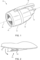
FIG. 1 illustrates a perspective view of a nacelle for an aircraft in accordance with various embodiments. -
FIG. 2 illustrates a perspective view of a portion of a nacelle for an aircraft with a latch handle rotated towards an open position, in accordance with various embodiments. -
FIG. 3 illustrates an outward view of a latch handle assembly on a nacelle, wherein the latch handle assembly comprises a latch handle comprising a notification feature, in accordance with various embodiments. -
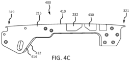
FIG. 4A, FIG. 4B , andFIG. 4C illustrate a latch handle arrangement comprising a latch handle body and a removable insert notification feature, in accordance with various embodiments. -
FIG. 5A ,FIG. 5B, and FIG. 5C illustrate the latch handle body, in accordance with various embodiments. -
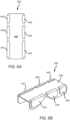
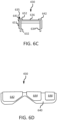
FIG. 6A, FIG. 6B ,FIG. 6C, and FIG. 6D illustrate top, isometric, front, and side views, respectively, of the removable insert notification feature, in accordance with various embodiments. -
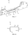
FIG. 7 illustrates a latch handle arrangement comprising a latch handle body and a removable insert notification feature, in accordance with various embodiments. -
FIG. 8 illustrates the removable insert notification feature ofFIG. 7 , in accordance with various embodiments. - The detailed description of exemplary embodiments herein makes reference to the accompanying drawings, which show exemplary embodiments by way of illustration and their best mode. While these exemplary embodiments are described in sufficient detail to enable those skilled in the art to practice the disclosure, it should be understood that other embodiments may be realized and that logical, material, and mechanical changes may be made without departing from the scope of the disclosure. Thus, the detailed description herein is presented for purposes of illustration only and not of limitation. For example, the steps recited in any of the method or process descriptions may be executed in any order and are not necessarily limited to the order presented. Furthermore, any reference to singular includes plural embodiments, and any reference to more than one component or step may include a singular embodiment or step. Also, any reference to attached, fixed, connected or the like may include permanent, removable, temporary, partial, full and/or any other possible attachment option. Additionally, any reference to "without contact" (or similar phrases) may also include reduced contact or minimal contact.
- As used herein, "outward" may define an element or portion of an element that is situated radially outer to or away from another, radially inward, element or portion of an element. Thus, an engine core may be situated radially inward of a fan casing, as described herein. As used herein, "inward" may define the element or portion of the element that is situated radially inward in relation to an outward element.
- Aircraft fan cowls are often held together with latch assemblies along various axial distances along the fan case. Fan cases may be encased by two fan cowls, which may be joined together with a latch mechanism (e.g., at the bottom of the fan cowls). For example, a fan cowl may include a latch assembly at the bottom of the fan cowl to allow the fan cowl to be hinged open to facilitate access to various fan case components.
- It is important that latches be in the closed or locked position prior to take off. If latches are left open, it may result in fan cowl departure during flight. In that regard, it may be advantageous for a latch handle to be highly visible when in the open position.
- Accordingly, latch handles may be provided to increase the visibility of the latch handles when the latch handles are in the open position. According to various embodiments, by increasing the visibility of the latch handles, it may be more apparent to ground crews when the latch handles are in the open position, decreasing the chance of a latch handle entering flight in an open position.
- Latch handle arrangements of the present disclosure comprise a latch handle body and a removable insert notification feature. Latch handle arrangement of the present disclosure may provide a quick, easy, and convenient way to service a latch handle to replace the notification feature in response to the notification feature becoming worn. For example, a color of the notification feature may begin to fade or the notification feature may be damaged or dirty. The used removable insert may be conveniently removed and replaced, such as via a snap-fit connection, with a new removable insert to quickly replace the used removable insert without having to disassemble the latch assembly.
- Referring to
FIG. 1 , anacelle 100 for a gas turbine engine is illustrated according to various embodiments.Nacelle 100 may comprise aninlet 110, afan cowl 120, and athrust reverser 130.Nacelle 100 may be coupled to apylon 140, which may mount thenacelle 100 to an aircraft wing or aircraft body.Nacelle 100 may further comprise anexhaust nozzle 150.Nacelle 100 surrounds the engine providing smooth aerodynamic surfaces for airflow around and into the engine.Fan cowl 120 typically comprises two halves. One half may be referred to as a first fan cowl and the other half may be referred to as a second fan cowl. The first fan cowl and second fan cowl are typically hinged to the pylon or to a frame structure attached at the top ofnacelle 100. Thenacelle 100 may be disposed about acenterline 105, which may also be the axis of rotation of an engine located within thenacelle 100. - With reference to
FIG. 2 , and with continuing reference toFIG 1 , a front view of a portion of an engine nacelle with a fan cowl latch handle rotated towards an open position is provided. According to various embodiments, latch handle 215 may be included at the bottom ofnacelle 100. A sidewall of latch handle 215 may be visible when in the open position.Latch handle 215 may include anotification feature 232 which may tend to visually draw attention from ground crew to indicate that latch handle 215 is not secured in a fully closed position. In various embodiments, any portion ofnotification feature 232 disposed on the sidewall of latch handle 215 may be covered or hidden in response to the latch handle moving to a closed position. Conversely, any portion ofnotification feature 232 disposed on the sidewall of latch handle 215 may become visible in response to the latch handle moving to an open position. - Latch assemblies typically comprise a latch hook and a latch keeper, wherein the latch hook is actuated by a latch handle located on a flow surface (e.g., an outward portion of the nacelle). Accordingly, in response to the handle being operated, the latch keeper disengages from the latch hook, allowing access to the oil tank, full authority digital engine control (FADEC) box, and other fan case components. With reference to
FIG. 3 , an outward view of alatch handle assembly 300 on a nacelle is provided. According to various embodiments, latchhandle assembly 300 may include latchhousing 310 and latch handle 215.Latch housing 310 may include afirst half 306 and asecond half 308.First half 306 oflatch housing 310 may be referred to as a keeper housing.First half 306 oflatch housing 310 may be attached to afirst cowl 342 according to various embodiments.Second half 308 oflatch housing 310 may be attached to asecond cowl 344 according to various embodiments. According to various embodiments,first cowl 342 may be a first fan cowl. According to various embodiments,second cowl 344 may be a second fan cowl. - According to various embodiments, latch handle 215 may include a
first end 319 and asecond end 321.First end 319 may be rotatable coupled tofirst half 306 oflatch housing 310. In this regard,second end 321 may rotate away fromsecond cowl 344 in response to latch handle 215 rotating to an open position. According to various embodiments, latchhousing 310 may be configured to enclose at least a portion of latch handle 215 such that the outward surface oflatch housing 310 and the outward surface of latch handle 215 are substantially flush relative to each other when in the closed position. In this manner, latchhandle assembly 300 may be aerodynamically efficient. - According to various embodiments, latch handle 215 may include
aperture 334.Aperture 334 may be disposed onlatch handle 215 in order to facilitate the opening oflatch handle 215. Typically, the opening of latch handle 215 from the closed position is facilitated by inserting an obj ect intoaperture 334 to depress a release member which may partially release latch handle 215 fromlatch housing 310. The latch handle 215 may then be further opened by prying latch handle 215 open. However, latch handle arrangements of the present disclosure may be configured to be opened via any suitable method without departing from the scope of the present disclosure. - According to various embodiments, latch handle 215 includes
notification feature 232 disposed at the side surface and/or the outward surface oflatch handle 215.Notification feature 232 may visually draw attention from ground crew, particularly when latch handle 215 is in the open position. According to various embodiments,notification feature 232 may comprise a removable insert disposed inlatch handle 215, as described in further detail herein. - With combined reference to
FIG. 4A, FIG. 4B , andFIG. 4C , alatch handle arrangement 400 is illustrated, in accordance with various embodiments.Latch handle arrangement 400 comprises alatch handle body 410 and aremovable insert 430.Removable insert 430 may be snap-fit to latchhandle body 410 by pushing the interlocking components of theremovable insert 430 and latchhandle body 410 together, as described herein. In this regard,removable insert 430 may be sufficiently flexible for snap-fit installation to latchhandle body 410. Furthermore, it is contemplated herein that, in addition to or in place of the snap-fit connection,removable insert 430 may be fastened to thelatch handle body 410.Removable insert 430 may be installed onto aninternal surface 418 oflatch handle body 410. In various embodiments,removable insert 430 comprises a plastic material. In various embodiments,removable insert 430 comprises a metal material. -
Latch handle body 410 generally comprises afirst sidewall 412, asecond sidewall 414, and atransverse wall 416 extending from thefirst sidewall 412 to thesecond sidewall 414. One or more apertures are disposed inlatch handle body 410 for accommodatingremovable insert 430. Furthermore, theremovable insert 430 may be visible via the one or more apertures. The illustrated embodiment depictsapertures latch handle body 410. However, any number of apertures may be disposed in thelatch handle body 410 without departing from the scope of the present disclosure. In various embodiments, at least one aperture is disposed on each side of the latch handle so that, in response to latchhandle body 410 being rotated to an open or partially open position, theremovable insert 430 is visible from either side oflatch handle body 410, thereby visually drawing attention from ground crew from both sides of thelatch handle body 410. - With reference to
FIG. 5A ,FIG. 5B, and FIG. 5C , thelatch handle body 410 is illustrated without a removable insert. In various embodiments, latchhandle body 410 may comprise one or more ribs extending from one of thesidewalls transverse wall 416. For example, arib 571 may extend fromsidewall 412 totransverse wall 416.Rib 571 may bend at a ninety degree angle, comprising a first portion extending parallel tosidewall 412 and a second portion extending parallel totransverse wall 416.Rib 571 may partially defineaperture 481 and partially defineaperture 483. In various embodiments, latchhandle body 410 comprisesrib 573 similarly extending fromsidewall 412 andtransverse wall 416 and partially definingaperture 483 andaperture 485.Latch handle body 410 may similarly compriserib 572 and/orrib 574 extending fromsidewall 414 totransverse wall 416. In various embodiments,ribs ribs Latch handle body 410 may be configured to rotate aboutaxis 590 with respect to a latch handle housing and/or a panel such as a fan cowl. - With combined reference to
FIG. 6A, FIG. 6B ,FIG. 6C, and FIG. 6D , theremovable insert 430 is illustrated, in accordance with various embodiments.Removable insert 430 generally comprises aninsert body 640 and at least one boss (e.g.,boss 641,boss 642,boss 643,boss 644,boss 645, and/or boss 646) protruding from theinsert body 640. Each boss may protrude from theinsert body 640 into an associated aperture. For example, with momentary additional reference toFIG. 4A ,boss 642 may protrude intoaperture 482, whereinboss 642 is visible from an external surface of thelatch handle body 410. In various embodiments,boss 642 may be substantially flush withlatch handle body 410 in the installed position, as illustrated inFIG. 4A . In various embodiments,boss 642 may be substantially flush with anexternal surface 419 oflatch handle body 410 in the installed position, as illustrated inFIG. 4A . However, in various embodiments,boss 642 may be recessed withinlatch handle body 410. Still further, in various embodiments,boss 642 may be slightly protruding fromlatch handle body 410. In various embodiments, each boss is separate and distinct from the other boss(es). Stated differently,boss 641 may be spaced apart fromboss 643,boss 642, etc. - With particular focus on
FIG. 6C ,boss 641 may comprise afirst portion 651 disposed on afirst sidewall 632 of theinsert body 640 and asecond portion 652 disposed on atransverse wall 636 of theinsert body 640, wherein theboss 641 wraps around acorner 635 of theinsert body 640. In this manner, theremovable insert 430 may be viewed from a top of the latch handle, as well as the sides of the latch handle.Boss 642 may be formed similar toboss 641. With momentary reference toFIG. 5B , apertures disposed inlatch handle body 410 may be sized to correspond to the geometry of the bosses ofremovable insert 430. Thus,aperture 482 may be partially disposed insidewall 414 and partially disposed intransverse wall 416. In various embodiments,boss 642 substantially fillsaperture 482. Likewise, the other apertures inlatch handle body 410 may be sized and positioned to correspond to the size and position of the other boss features ofremovable insert 430. -
Removable insert 430 may comprise a substantially "U"-shaped geometry as illustrated inFIG. 6C . As theremovable insert 430 snap-fits into latch handle body 410 (seeFIG. 4B )latch handle body 410 may similarly comprise a substantially "U"-shaped geometry. - According to various embodiments,
removable insert 430 may include text or characters which may visually alert ground crew. According to various embodiments,removable insert 430 may comprise a bright paint, coating, or any other form of colored surface such that there is substantial contrast betweenremovable insert 430 and the rest of the latch handle assembly and/or nacelle assembly. According to various embodiments,removable insert 430 is made from a material that comprises a bright colored surface such that there is substantial contrast betweenremovable insert 430 and the rest of the latch handle assembly and/or nacelle assembly.Latch handle body 410 may comprise a first color, such as grey, black, silver, or any other color.Removable insert 430 may comprise a second color, such as orange, red, or any other color. The second color may be more bright than the first color to draw attention from ground grey whenremovable insert 430 is visible. According to various embodiments,removable insert 430 may comprise a reflective surface such as a reflective tape, a reflective sticker, or any other form of reflective surface which may increase the visibility of the outward surface ofremovable insert 430. - With reference to
FIG. 7 and FIG. 8 , alatch handle arrangement 700 is illustrated, in accordance with various embodiments.Latch handle arrangement 700 comprises alatch handle body 710 and aremovable insert 730.Latch handle arrangement 700 may be similar to latchhandle arrangement 400 ofFIG. 4A except thatremovable insert 730 is only visible from thesidewalls latch handle body 710. In this regard, latchhandle body 710 may comprise anaperture 781 disposed insidewall 714. A second, similar, aperture may also be disposed insidewall 712.Removable insert 730 may snap-fit intoaperture 781.Removable insert 730 may comprise aninsert body 740 and a first boss 741 protruding frominsert body 740.Removable insert 730 may further comprise asecond boss 742 protruding frominsert body 740.Insert body 740 may comprise atransverse wall 736, afirst sidewall 732, and asecond sidewall 734. First boss 741 may be disposed onfirst sidewall 732.Second boss 742 may be disposed onsecond sidewall 734. - In accordance with various embodiments, first boss 741 may comprise a high aspect ratio. In various embodiments, first boss 741 comprises an aspect ratio of between 2:1 and 30:1, wherein the aspect ratio, as used herein, is a ratio of the
maximum length 792 to themaximum width 794. In various embodiments, first boss 741 comprises an aspect ratio of between 2:1 and 20:1. In various embodiments, first boss 741 comprises an aspect ratio of between 4:1 and 20:1. In various embodiments, first boss 741 comprises an aspect ratio of between 6:1 and 20:1. In various embodiments, first boss 741 comprises an aspect ratio of up to 20:1. - Benefits, other advantages, and solutions to problems have been described herein with regard to specific embodiments. Furthermore, the connecting lines shown in the various figures contained herein are intended to represent exemplary functional relationships and/or physical couplings between the various elements. It should be noted that many alternative or additional functional relationships or physical connections may be present in a practical system. However, the benefits, advantages, solutions to problems, and any elements that may cause any benefit, advantage, or solution to occur or become more pronounced are not to be construed as critical, required, or essential features or elements of the disclosed embodiments. The scope of the claimed embodiments is accordingly to be limited by nothing other than the appended claims, in which reference to an element in the singular is not intended to mean "one and only one" unless explicitly so stated, but rather "one or more." Moreover, where a phrase similar to "at least one of A, B, or C" is used in the claims, it is intended that the phrase be interpreted to mean that A alone may be present in an embodiment, B alone may be present in an embodiment, C alone may be present in an embodiment, or that any combination of the elements A, B and C may be present in a single embodiment; for example, A and B, A and C, B and C, or A and B and C. Different cross-hatching is used throughout the figures to denote different parts but not necessarily to denote the same or different materials.
- Systems, methods and apparatus are provided herein. In the detailed description herein, references to "one embodiment", "an embodiment", "an example embodiment", etc., indicate that the embodiment described may include a particular feature, structure, or characteristic, but every embodiment may not necessarily include the particular feature, structure, or characteristic. Moreover, such phrases are not necessarily referring to the same embodiment. Further, when a particular feature, structure, or characteristic is described in connection with an embodiment, it is submitted that it is within the knowledge of one skilled in the art to affect such feature, structure, or characteristic in connection with other embodiments whether or not explicitly described. After reading the description, it will be apparent to one skilled in the relevant art(s) how to implement the disclosure in alternative embodiments.
- Furthermore, no element, component, or method step in the present disclosure is intended to be dedicated to the public regardless of whether the element, component, or method step is explicitly recited in the claims. As used herein, the terms "comprises", "comprising", or any other variation thereof, are intended to cover a non-exclusive inclusion, such that a process, method, article, or apparatus that comprises a list of elements does not include only those elements but may include other elements not expressly listed or inherent to such process, method, article, or apparatus.
Claims (15)
- A latch handle arrangement (400) comprising:a latch handle body (410) comprising a first sidewall (412), a second sidewall (414), and a transverse wall (416) extending from the first sidewall (412) to the second sidewall (414);a first aperture (481, 483, 485) disposed in the latch handle body (410); anda removable insert (430) coupled to the latch handle body (410), the removable insert (430) comprising an insert body (640), a first boss (641, 643, 645) protruding from the insert body (640) into the first aperture (481, 483, 485), wherein the first boss (641, 643, 645) is visible from an external surface of the latch handle body (410),wherein the first aperture (481, 483, 485) is disposed in the first sidewall (412) and the transverse wall (416).
- The latch handle arrangement (400) of any claim 1, wherein the first boss (641, 643, 645) is configured to be visible from the external surface in response to the latch handle body (410) moving to an open position.
- The latch handle arrangement (400) of claim 1 or 2, wherein the latch handle body (410) comprises a substantially U-shaped geometry, and the insert body (640) optionally comprises the substantially U-shaped geometry.
- The latch handle arrangement (400) of any preceding claim, wherein the first boss (641) is disposed on a sidewall (632) of the insert body (640) and a transverse wall (636) of the insert body (640), wherein the first boss (641) wraps around a corner (635) of the insert body (640).
- The latch handle arrangement (400) of any preceding claim, wherein the first boss is substantially flush with the latch handle body (410).
- The latch handle arrangement (400) of any preceding claim, further comprising a second aperture (482, 484, 486) disposed in the latch handle body (410).
- The latch handle arrangement (400) of claim 6, further comprising a second boss (642, 644, 646) protruding from the insert body (640) into the second aperture (482, 484, 486), wherein the second boss (642, 644, 646) is visible from the external surface of the latch handle body (410).
- The latch handle arrangement (400) of any of claims 1 to 5, wherein:the latch handle arrangement further comprises a second aperture (482, 484, 486) disposed in the second sidewall (414) of the latch handle body (410);the removable insert (430) further comprises a second boss (642, 644, 646) protruding from the insert body (640) into the second aperture (482, 484, 486); andthe second boss (642, 644, 646) is visible from an external surface of the latch handle body (410).
- The latch handle arrangement (400) of claim 8, wherein the first boss (641, 643, 645) and the second boss (642, 644, 646) are configured to be visible from the external surface in response to the latch handle body (410) moving to an open position.
- The latch handle arrangement (400) of claim 8 or 9, wherein the first boss (641, 643, 645) and the second boss (642, 644, 646) are configured to be hidden in response to the latch handle body (410) moving to a closed position.
- The latch handle arrangement (400) of any preceding claim, wherein the first aperture (481, 483, 485) comprises an aspect ratio of up to 20:1.
- The latch handle arrangement (400) of any preceding claim, wherein the latch handle body (410) comprises a first color and the removable insert (430) comprises a second color.
- The latch handle arrangement (400) of any preceding claim, wherein the removable insert (430) is configured to be snap-fit into the latch handle body (410).
- A nacelle (100) comprising:a first panel;a latch assembly (300) comprising a latch housing (310) and a latch handle arrangement (400), the latch assembly (300) configured to secure the first panel in a closed position,wherein the latch handle arrangement (400) comprises the latch handle arrangement of any preceding claim.
- The nacelle (100) of claim 14, wherein at least a portion of the removable insert (430) is hidden by the panel in response to the latch handle arrangement (400) moving to a locked position.
Applications Claiming Priority (3)
| Application Number | Priority Date | Filing Date | Title |
|---|---|---|---|
| US202063020404P | 2020-05-05 | 2020-05-05 | |
| US17/220,442 US11773623B2 (en) | 2020-05-05 | 2021-04-01 | Systems and methods for high visibility latch handle |
| EP21172341.6A EP3907140B1 (en) | 2020-05-05 | 2021-05-05 | Systems and methods for high visibility latch handle |
Related Parent Applications (1)
| Application Number | Title | Priority Date | Filing Date |
|---|---|---|---|
| EP21172341.6A Division EP3907140B1 (en) | 2020-05-05 | 2021-05-05 | Systems and methods for high visibility latch handle |
Publications (3)
| Publication Number | Publication Date |
|---|---|
| EP4464601A2 true EP4464601A2 (en) | 2024-11-20 |
| EP4464601A3 EP4464601A3 (en) | 2025-01-01 |
| EP4464601B1 EP4464601B1 (en) | 2026-04-08 |
Family
ID=75825576
Family Applications (2)
| Application Number | Title | Priority Date | Filing Date |
|---|---|---|---|
| EP21172341.6A Active EP3907140B1 (en) | 2020-05-05 | 2021-05-05 | Systems and methods for high visibility latch handle |
| EP24199557.0A Active EP4464601B1 (en) | 2020-05-05 | 2021-05-05 | Systems and methods for high visibility latch handle |
Family Applications Before (1)
| Application Number | Title | Priority Date | Filing Date |
|---|---|---|---|
| EP21172341.6A Active EP3907140B1 (en) | 2020-05-05 | 2021-05-05 | Systems and methods for high visibility latch handle |
Country Status (2)
| Country | Link |
|---|---|
| US (1) | US11773623B2 (en) |
| EP (2) | EP3907140B1 (en) |
Family Cites Families (15)
| Publication number | Priority date | Publication date | Assignee | Title |
|---|---|---|---|---|
| US7454933B1 (en) * | 2005-03-14 | 2008-11-25 | The Eastern Company | Handle and housing assembly |
| US7185926B2 (en) * | 2005-03-25 | 2007-03-06 | Hartwell Corporation | Preloaded latch mechanism |
| US7802826B2 (en) | 2007-02-10 | 2010-09-28 | R The Boeing Company | Latch assembly |
| WO2011115792A1 (en) * | 2010-03-18 | 2011-09-22 | Alcoa Inc. | Latch with adjustable handle |
| FR2973421B1 (en) | 2011-03-29 | 2013-04-05 | Aircelle Sa | LOCKING DEVICE WITH MECHANICAL DETECTION OF CLOSURE AND OPENING |
| US8317237B1 (en) | 2011-08-26 | 2012-11-27 | GM Global Technology Operations LLC | Release handle for vehicle closure lid latch |
| WO2014015193A1 (en) * | 2012-07-18 | 2014-01-23 | Container International, Inc. | Lock ring for securing a container lid |
| CN104929456B (en) | 2014-03-13 | 2018-05-22 | Qrp股份有限公司 | Elbow connection rod is latched |
| US9624693B2 (en) | 2015-03-03 | 2017-04-18 | The Boeing Company | Integrated locks with visual indicators for aircraft galley systems |
| US9945150B2 (en) * | 2015-03-27 | 2018-04-17 | Rohr, Inc. | High visibility latch handle |
| WO2017127776A2 (en) | 2016-01-22 | 2017-07-27 | Centrix Aero, LLC | Dual purpose latch |
| US10267060B2 (en) | 2016-12-21 | 2019-04-23 | The Boeing Company | Apparatuses and methods for cowl latch indication |
| DE102017223684A1 (en) * | 2017-12-22 | 2019-06-27 | Lufthansa Technik Ag | Locking device for flaps on aircraft |
| US11142326B2 (en) | 2018-07-27 | 2021-10-12 | The Boeing Company | Mechanism for indicating position of a latch mechanism for an aircraft nacelle |
| US11338931B2 (en) | 2018-11-20 | 2022-05-24 | Rohr, Inc. | High visibility panel latch |
-
2021
- 2021-04-01 US US17/220,442 patent/US11773623B2/en active Active
- 2021-05-05 EP EP21172341.6A patent/EP3907140B1/en active Active
- 2021-05-05 EP EP24199557.0A patent/EP4464601B1/en active Active
Also Published As
| Publication number | Publication date |
|---|---|
| EP3907140B1 (en) | 2024-09-11 |
| US20210348419A1 (en) | 2021-11-11 |
| US11773623B2 (en) | 2023-10-03 |
| EP3907140A1 (en) | 2021-11-10 |
| EP4464601A3 (en) | 2025-01-01 |
| EP4464601B1 (en) | 2026-04-08 |
Similar Documents
| Publication | Publication Date | Title |
|---|---|---|
| US9945150B2 (en) | High visibility latch handle | |
| EP3907139B1 (en) | Systems and methods for latch hook length adjustment | |
| EP0756557B1 (en) | An aircraft propulsive power unit | |
| US11125112B2 (en) | Inner fixed structure leading edge latch | |
| CN108216657B (en) | Apparatus and method for cowl latch indication | |
| US10618664B2 (en) | Self-latching nacelle | |
| US20160280383A1 (en) | Fan cowl balking latch | |
| US11718409B2 (en) | Nacelle with independent opening thrust reverser section | |
| US10710736B2 (en) | Latch indication system and method for a fan cowl of an air vehicle | |
| US11619191B2 (en) | Bypass propulsion unit, comprising a thrust reverser with movable cascades | |
| EP3326916B1 (en) | Nacelle latch alignment | |
| EP4464601B1 (en) | Systems and methods for high visibility latch handle | |
| CN110761630B (en) | Mechanism for indicating the position of a latch mechanism for an aircraft cabin | |
| EP3447272B1 (en) | Safety maintenance panel for a thrust reverser | |
| EP3712073B1 (en) | Self-engaging fan cowl hook latch | |
| EP3650334A1 (en) | Pressure relief assembly | |
| EP3656677A1 (en) | High visibility panel latch | |
| US11878808B2 (en) | Nacelle inlet structure fitting with locator clip and hoist bracket | |
| EP3747774B1 (en) | Latch and method for operating said latch | |
| EP3878753B1 (en) | Latch assembly | |
| US20200172255A1 (en) | Guided fan cowl hinge | |
| EP4019407B1 (en) | Fan cowl failsafe gooseneck assembly |
Legal Events
| Date | Code | Title | Description |
|---|---|---|---|
| PUAI | Public reference made under article 153(3) epc to a published international application that has entered the european phase |
Free format text: ORIGINAL CODE: 0009012 |
|
| STAA | Information on the status of an ep patent application or granted ep patent |
Free format text: STATUS: THE APPLICATION HAS BEEN PUBLISHED |
|
| AC | Divisional application: reference to earlier application |
Ref document number: 3907140 Country of ref document: EP Kind code of ref document: P |
|
| AK | Designated contracting states |
Kind code of ref document: A2 Designated state(s): AL AT BE BG CH CY CZ DE DK EE ES FI FR GB GR HR HU IE IS IT LI LT LU LV MC MK MT NL NO PL PT RO RS SE SI SK SM TR |
|
| PUAL | Search report despatched |
Free format text: ORIGINAL CODE: 0009013 |
|
| AK | Designated contracting states |
Kind code of ref document: A3 Designated state(s): AL AT BE BG CH CY CZ DE DK EE ES FI FR GB GR HR HU IE IS IT LI LT LU LV MC MK MT NL NO PL PT RO RS SE SI SK SM TR |
|
| RIC1 | Information provided on ipc code assigned before grant |
Ipc: E05B 41/00 20060101ALI20241125BHEP Ipc: E05B 15/00 20060101ALI20241125BHEP Ipc: B64D 29/06 20060101AFI20241125BHEP |
|
| STAA | Information on the status of an ep patent application or granted ep patent |
Free format text: STATUS: REQUEST FOR EXAMINATION WAS MADE |
|
| 17P | Request for examination filed |
Effective date: 20250701 |
|
| GRAP | Despatch of communication of intention to grant a patent |
Free format text: ORIGINAL CODE: EPIDOSNIGR1 |
|
| STAA | Information on the status of an ep patent application or granted ep patent |
Free format text: STATUS: GRANT OF PATENT IS INTENDED |
|
| INTG | Intention to grant announced |
Effective date: 20251030 |
|
| GRAS | Grant fee paid |
Free format text: ORIGINAL CODE: EPIDOSNIGR3 |
|
| GRAA | (expected) grant |
Free format text: ORIGINAL CODE: 0009210 |
|
| STAA | Information on the status of an ep patent application or granted ep patent |
Free format text: STATUS: THE PATENT HAS BEEN GRANTED |
|
| AC | Divisional application: reference to earlier application |
Ref document number: 3907140 Country of ref document: EP Kind code of ref document: P |
|
| AK | Designated contracting states |
Kind code of ref document: B1 Designated state(s): AL AT BE BG CH CY CZ DE DK EE ES FI FR GB GR HR HU IE IS IT LI LT LU LV MC MK MT NL NO PL PT RO RS SE SI SK SM TR |
|
| REG | Reference to a national code |
Ref country code: CH Ref legal event code: F10 Free format text: ST27 STATUS EVENT CODE: U-0-0-F10-F00 (AS PROVIDED BY THE NATIONAL OFFICE) Effective date: 20260408 Ref country code: GB Ref legal event code: FG4D |
|
| REG | Reference to a national code |
Ref country code: DE Ref legal event code: R096 Ref document number: 602021051957 Country of ref document: DE |