EP4464577A1 - A tool and a method for mounting a cockpit to the body-in-white of a motor vehicle cab - Google Patents
A tool and a method for mounting a cockpit to the body-in-white of a motor vehicle cab Download PDFInfo
- Publication number
- EP4464577A1 EP4464577A1 EP23174007.7A EP23174007A EP4464577A1 EP 4464577 A1 EP4464577 A1 EP 4464577A1 EP 23174007 A EP23174007 A EP 23174007A EP 4464577 A1 EP4464577 A1 EP 4464577A1
- Authority
- EP
- European Patent Office
- Prior art keywords
- crosspiece
- tool
- white
- centering pin
- positioning holes
- Prior art date
- Legal status (The legal status is an assumption and is not a legal conclusion. Google has not performed a legal analysis and makes no representation as to the accuracy of the status listed.)
- Pending
Links
- 238000000034 method Methods 0.000 title claims description 12
- 230000002093 peripheral effect Effects 0.000 claims description 38
- 230000000295 complement effect Effects 0.000 description 3
- 238000003780 insertion Methods 0.000 description 3
- 230000037431 insertion Effects 0.000 description 3
- 238000004378 air conditioning Methods 0.000 description 2
- 238000004590 computer program Methods 0.000 description 1
- 238000010276 construction Methods 0.000 description 1
- 239000003292 glue Substances 0.000 description 1
- 238000010438 heat treatment Methods 0.000 description 1
- 238000012423 maintenance Methods 0.000 description 1
- 238000004519 manufacturing process Methods 0.000 description 1
- 230000005226 mechanical processes and functions Effects 0.000 description 1
- 238000012986 modification Methods 0.000 description 1
- 230000004048 modification Effects 0.000 description 1
- 238000009423 ventilation Methods 0.000 description 1
- 238000003466 welding Methods 0.000 description 1
Images




Classifications
-
- B—PERFORMING OPERATIONS; TRANSPORTING
- B62—LAND VEHICLES FOR TRAVELLING OTHERWISE THAN ON RAILS
- B62D—MOTOR VEHICLES; TRAILERS
- B62D65/00—Designing, manufacturing, e.g. assembling, facilitating disassembly, or structurally modifying motor vehicles or trailers, not otherwise provided for
- B62D65/02—Joining sub-units or components to, or positioning sub-units or components with respect to, body shell or other sub-units or components
- B62D65/024—Positioning of sub-units or components with respect to body shell or other sub-units or components
- B62D65/026—Positioning of sub-units or components with respect to body shell or other sub-units or components by using a jig or the like; Positioning of the jig
-
- B—PERFORMING OPERATIONS; TRANSPORTING
- B62—LAND VEHICLES FOR TRAVELLING OTHERWISE THAN ON RAILS
- B62D—MOTOR VEHICLES; TRAILERS
- B62D25/00—Superstructure or monocoque structure sub-units; Parts or details thereof not otherwise provided for
- B62D25/08—Front or rear portions
- B62D25/14—Dashboards as superstructure sub-units
- B62D25/145—Dashboards as superstructure sub-units having a crossbeam incorporated therein
-
- B—PERFORMING OPERATIONS; TRANSPORTING
- B62—LAND VEHICLES FOR TRAVELLING OTHERWISE THAN ON RAILS
- B62D—MOTOR VEHICLES; TRAILERS
- B62D65/00—Designing, manufacturing, e.g. assembling, facilitating disassembly, or structurally modifying motor vehicles or trailers, not otherwise provided for
- B62D65/02—Joining sub-units or components to, or positioning sub-units or components with respect to, body shell or other sub-units or components
- B62D65/14—Joining sub-units or components to, or positioning sub-units or components with respect to, body shell or other sub-units or components the sub-units or components being passenger compartment fittings, e.g. seats, linings, trim, instrument panels
Definitions
- the disclosure relates generally to the mounting of a cockpit to the body-in-white of a motor vehicle cab.
- the disclosure relates to a tool and a method for mounting a cockpit to the body-in-white of a motor vehicle cab.
- the disclosure can be applied in heavy-duty vehicles, such as trucks, buses, and construction equipment. Although the disclosure may be described with respect to a truck, the disclosure is not restricted to any particular vehicle.
- the front part of a motor vehicle driver compartment is delimited by a dashboard that is supported by a crosspiece, also known as Cross-Truck-Beam (CTB); which is at least partly metallic and forms a structural element of the vehicle.
- CTB Cross-Truck-Beam
- the assembly formed by the crosspiece and the dashboard, called the "cockpit" has a structural mechanical function and serves as a support for numerous elements including aeraulic elements, such as air ducts or a ventilation system and/or or air conditioning. Such aeraulic elements can also form part of the cockpit.
- this crosspiece In order to ensure the stability of the crosspiece, and therefore of the cockpit, after its assembly, this crosspiece must be positioned precisely with respect to the structure of the vehicle.
- the centering of the crosspiece with respect to the structure of the vehicle is generally carried out by an assistance tool that carries the cockpit or the crosspiece and positions it with respect to the structure of the vehicle by using specific sensors to measure the gap between the cockpit and the lateral extremities of the vehicle structure as a reference. Once correctly positioned, the crosspiece is fixed by its ends to the structure of the vehicle.
- Such a method is relatively complex and expensive in terms of invest. In addition, it may require dedicated additional actuators to adjust the position of the cockpit, which increases the assembly costs.
- Another existing method involves two centering pins, respectively a left centering pin and a right centering pin, hold by the structure of the vehicle, said centering pins being received in corresponding holes formed in the crosspiece of the cockpit, respectively a circular hole on the left side thereof and an oblong hole on the right side thereof.
- the left centering pin has a shape substantially complementary to the one of the circular hole, thus centering the cockpit both in a vehicle vertical direction and in a vehicle transverse direction
- the right centering pin has a cylindrical shape that contacts the crosspiece only in two points aligned in a vehicle vertical direction, thus centering the cockpit only in said vehicle vertical direction.
- Such a method is however adapted for a Left Hand Drive (LHD) vehicle, but not for a Right Hand Drive (RHD) vehicle.
- the RHD vehicles need to invert the position of the holes on the cockpit with respect to LHD vehicles to keep the same centering accuracy.
- Such method thus requires dedicated stamping tools for forming the holes in the crosspiece of a RHD vehicle, which increases the global costs supported by the automotive manufacturers.
- the invention aims to overcome these drawbacks by proposing a tool for mounting a cockpit to a body-in-white of a motor vehicle cab, the cockpit comprising a crosspiece extending in a vehicle transverse direction and a dashboard, the tool comprising:
- the disclosure relates to a tool for mounting a cockpit to a body-in-white of a motor vehicle cab, the cockpit comprising a crosspiece extending in a vehicle transverse direction and a dashboard, the tool comprising:
- the tool of the disclosure makes it possible to precisely position the crosspiece of a cockpit relative to the body-in-white of a motor vehicle cab before fixing it thereon.
- one of the centering pins of the tool has a specific shape that blocks the position of the crosspiece relative to the body-in-white along a transverse direction and a vertical direction but allows a slight rotation of said crosspiece about a longitudinal axis.
- This slight rotation avoids worn during the insertion of the centering pin in the corresponding positioning hole of the crosspiece when the crosspiece and/or the body-in-white are slightly inclined relative to an ideal mounting position in which one of the positioning holes are in contact with one of the centering pins of the tool in two points aligned in a vehicle vertical direction and in two points aligned in a vehicle transverse direction.
- the disclosure makes it possible to overcome the need to use a complex assistance tool to achieve the positioning of the cockpit relative to the vehicle. This thus makes it possible to reduce the costs of assembly, manufacture and maintenance of an assistance tool, the latter being necessary only to support the cockpit or the crosspiece of the cockpit.
- the tool of the disclosure may be easily modified to invert the positions of the left and right centering pins, thus offering the same centering accuracy for both LHD and RHD vehicles.
- the other one of the said left centering pin and of the said right centering pin is defined by upper and lower curved peripheral areas and left and right curved peripheral areas, the upper and lower curved peripheral areas having, in a section plane parallel to the vertical plane, a circular arc shape inscribed in a first circle, the diameter of the first circle corresponding substantially to the dimension of the corresponding left or right positioning holes along a vehicle vertical direction, and the left and right curved peripheral areas having, in a section plane parallel to the vertical plane, a circular arc shape inscribed in a second circle, the diameter of the second circle corresponding substantially to the dimension of the corresponding left or right positioning holes along a vehicle transverse direction.
- the upper, respectively the lower, curved peripheral area is linked to the left, respectively the right, curved peripheral area via a planar peripheral area.
- the first and the second circles have the same center.
- the left centering pin and the right centering pin are removably attached to the support plate.
- the left centering pin or the right centering pin is made of a first, a second and a third parallel spindles, wherein the first spindle is fixedly attached to the support plate and the second and third spindles are slidably fixed to the support plate such that they are movable between a deployed position, in which they extend at both sides of a top portion of the first spindle, and a retracted position, in which they extend at both sides of a bottom portion of the spindle.
- the second and third spindles are configured to be housed into the left or right positioning hole formed respectively in the crosspiece and the body-in-white in the mounting position of the tool and when they are in their deployed position, and to be out of said left or right positioning hole in the mounting position of the tool and when they are in their retracted position.
- the first spindle has a cylindrical shape, the diameter of the first spindle corresponding substantially to the dimension of the left or right positioning hole along a vehicle vertical direction,
- the first and the second circles have the same radius.
- the special cross-section has two axes of symmetry that are crossing by the center of the section and that are respectively parallel to the vehicle transverse direction and to a vertical axis perpendicular to the vehicle longitudinal and transverse directions.
- each of the left and right centering pins has a tapered end for optimum engagement into the corresponding holes.
- the special cross-section is such that it can be circumscribed inside a rectangle.
- the disclosure relates to a method for mounting a cockpit to a body-in-white of a motor vehicle cab, the cockpit comprising a crosspiece extending in a vehicle transverse direction and a dashboard, the crosspiece and the body-in-white being respectively provided with left and right positioning holes, said left and right positioning holes having preferably an oblong shape and being preferably defined by a larger dimension along a vehicle transverse direction than along a vehicle vertical direction, the method comprising:
- the disclosure relates to a motor vehicle cab comprising a body-in-white and a dashboard fixedly connected thereto through a crosspiece extending in a vehicle transverse direction, wherein the crosspiece and the body-in-white each comprises a left mounting interface and a right mounting interface, said left mounting interface, respectively said right mounting interface, being provided with a left positioning hole, respectively a right positioning hole, said left and right positioning holes having each an oblong shape.
- the oblong shape of the left and right positioning holes is defined by a larger dimension along the vehicle transverse direction than along a vehicle vertical direction.
- the left and right positioning holes of the body-in-white have the same shape as the left and right positioning holes of the crosspiece.
- the left and right positioning holes of the crosspiece and of the body-in-white have a substantially rectangular shape in a section plane perpendicular to a vehicle longitudinal direction.
- the disclosure relates to a motor vehicle comprising a motor vehicle cab according to any of the embodiments set forth herein above.
- the crosspiece 1 extends along a vehicle transverse direction Y and comprises, at each of its ends, a fixing interface 6, 7 configured to be attached to the body-in-white 4 of the vehicle.
- each fixing interface 6, 7 may have a flat shape with a rectangular basis that cooperates with respective flat fixing areas of the body-in-white 4.
- the fixing interfaces 6, 7 and the corresponding fixing areas may have several through-holes, which have corresponding locations for the passage of bolts (not shown). These bolts enable fixing the crosspiece 1 to the body-in-white 4.
- the crosspiece 1 could be fixed on the body-in-white 4 by any means equivalent to bolts, like e.g. welding, rivets, glue areas, clip fixing devices, etc.
- the crosspiece 1 and the body-in-white 4 comprises a left mounting interface 8, respectively 18, and a right mounting interface 8', respectively 18', allowing the crosspiece 1 to be temporary connected on a mounting tool 10.
- the left, respectively the right, mounting interface 8, 8' of the crosspiece 1 is provided with a left, respectively a right, positioning hole 9, 9', said positioning holes 9, 9' having a substantially rectangular shape in a section plane parallel to the vertical plane, as shown in FIG. 5a and FIG. 5b .
- Said rectangular shape is defined by a larger dimension along a vehicle transverse direction Y than along a vehicle vertical direction Z.
- the left, respectively the right, mounting interface 18, 18' of the body-in-white 4 is provided with a left, respectively a right, positioning hole 19, 19', said positioning holes 19, 19' having the same shape as the positioning holes 9, 9' in a section plane parallel to the vertical plane.
- the tool 10 comprises a support plate 11 extending in a vertical plane, and one left centering pin 12 and one right centering pin 12' extending in a direction perpendicular to the vertical plane.
- the centering pins 12, 12' are configured to be respectively inserted into the left, respectively the right, positioning holes 9, 19, 9', 19' formed respectively in the crosspiece 1 and the body-in-white 4 in a mounting position of the tool 10, illustrated in Figs 4a and 4b .
- the centering pins 12, 12' may advantageously be provided with a tapered end for optimum engagement into the corresponding positioning holes.
- the right centering pin 12' has a cylindrical shape and is configured to contact the crosspiece 1, respectively the body-in-white 4, in two points P1, P2 aligned in a vehicle vertical direction in the mounting position of the tool 10, thus preventing a movement of the right centering pin 12' relative to the crosspiece 1 and the body-in-white 4 along said vehicle vertical direction.
- said right centering pin provides an axial stop along vertical direction.
- the left centering pin 12 has an oblong cross-section, e.g.
- This special cross-section is defined by two axes of symmetry that are crossing by the center of the section and that are respectively parallel to the vehicle transverse direction Y and to a vertical axis Z perpendicular to the vehicle longitudinal and transverse directions X, Y and is configured to be circumscribed inside a rectangle.
- the left centering pin 12 is defined by upper and lower curved peripheral areas 121, 122 and left and right curved peripheral areas 123, 124, the upper and lower curved peripheral areas 121, 122 having, in a section plane parallel to the vertical plane, a circular arc shape inscribed in a first circle C1, the diameter D1 of the first circle C1 corresponding substantially to the dimension L1 of the left positioning holes 9, 19 along a vehicle vertical direction, and the left and right curved peripheral areas 123, 124 having, in a section plane parallel to the vertical plane, a circular arc shape inscribed in a second circle C2, the diameter D2 of the second circle C2 corresponding substantially to the dimension L2 of the left positioning holes 9, 19 along a vehicle transverse direction.
- the upper curved peripheral area 121 is linked to the left and right curved peripheral areas 123, 124, respectively, via upper left and right planar peripheral areas 125, 126, and the lower curved peripheral area 122 is linked to the left and right curved peripheral areas 123, 124, respectively, via lower left and right planar peripheral areas 127, 128.
- the first and the second circles C1, C2 have the same center X0.
- the crosspiece 1 and the body-in-white 4 may thus rotate clockwise relative to the left centering pin 12 around a longitudinal axis passing through said center X0 to reach a second position shown in FIG. 9 , in which they have pivoted at an angle ⁇ max relative to their position in Fig. 8 .
- the upper right planar peripheral area 126 and the lower left planar peripheral area 127 of the centering pin 12 abut against the crosspiece 1 and the body-in-white 4.
- This second mounting position may occur if the crosspiece 1 and the body-in-white 4 are not straight or sag relative to their ideal mounting position illustrated in Fig. 8 .
- centering pin 12 is also adapted to be inserted in the left positioning holes 9, 19 for any intermediate positions thereof between the ideal mounting position illustrated in Fig. 8 and the second position illustrated in Fig. 9 .
- the crosspiece 1 and the body-in-white 4 may also rotate counterclockwise relative to the left centering pin 12 around a longitudinal axis passing through the center X0 to reach a third position (not shown), in which they have pivoted at an angle ⁇ max relative to their position in Fig. 8 .
- a third position (not shown), in which they have pivoted at an angle ⁇ max relative to their position in Fig. 8 .
- the upper left planar peripheral area 125 and the lower right planar peripheral area 128 abut against the crosspiece 1 and the body-in-white 4.
- centering pin 12 is also adapted to be inserted in the left positioning holes 9, 19 for any intermediate positions thereof between the ideal mounting position illustrated in Fig. 8 and said third position.
- the tool 10 avoids wear of the centering pins during the insertion of the centering pins in the corresponding positioning holes of the crosspiece 1 and the body-in-white 4 whatever the positions of the crosspiece 1 and the body-in-white 4 relative to their ideal mounting position illustrated in Fig. 8 .
- the left centering pin 12 and the right centering pin 12' may be removably attached to the support plate 11. Accordingly, the tool 10 may be easily modified to invert the positions of the left and right centering pins 12, 12', as illustrated in FIG. 6a and FIG. 6b, and FIG. 7a and FIG. 7b .
- the tool 10 comprises a left centering pin 12' and a right centering pin 12 extending along a longitudinal direction.
- the centering pins 12', 12 are configured to be respectively inserted into the left, respectively the right, positioning holes 9, 19, 9', 19' formed respectively in the crosspiece 1 and the body-in-white 4 in the mounting position of the tool 10, illustrated in Figs 6a and 6b .
- the left centering pin 12' has a cylindrical shape and is configured to contact the crosspiece 1, respectively the body-in-white 4, in two points P1, P2 aligned in a vehicle vertical direction in the mounting position of the tool 10, thus preventing a movement of the left centering pin 12' relative to the crosspiece 1 and the body-in-white 4 along said vehicle vertical direction
- the right centering pin 12 has a trapezoid shape that is partially complementary to the shape of the right positioning holes 9', 19' and is configured to contact the crosspiece 1, respectively the body-in-white 4, in two points P3, P4 aligned in a vehicle vertical direction and in two points P5, P6 aligned in a vehicle transverse direction in the mounting position of the tool 10, thus preventing a movement of the right centering pin 12 relative to the crosspiece 1 and the body-in-white 4 along said vehicle vertical direction and said vehicle transverse direction.
- the right centering pin 12 having the specific shape shown in Fig. 8 , and the right positioning holes 9', 19' of the crosspiece 1 and of the body-in-white 4 having the same shape as the left positioning holes 9, 19 thereof, the crosspiece 1 and the body-in-white 4 may thus rotate clockwise relative to the right centering pin 12 around a longitudinal axis passing through the center X0 to reach a second position, shown in Fig. 9 , in which the crosspiece 1 and the body-in-white 4 have pivoted at an angle ⁇ max relative to their position in Fig. 8 , or any intermediate positions between the position illustrated in Fig. 8 and this second position.
- the crosspiece 1 and the body-in-white 4 may also rotate counterclockwise relative to the right centering pin 12 around a longitudinal axis passing through the center X0 to reach a third position (not shown), in which the crosspiece 1 and the body-in-white 4 have pivoted at an angle ⁇ max relative to their position in Fig. 8 , or any intermediate positions between the position illustrated in Fig. 8 and this third position.
- the tool 10 comprises a support plate 11 extending in a vertical plane, and two sets of spindles, respectively a left set comprising a first left spindle 14, a second left spindle 15, and a third left spindle 16, and a right set comprising a first right spindle 14', a second right spindle 15', and a third right spindle 16'.
- the first left spindle 14, respectively the first right spindle 14', is fixedly attached to the support plate 11 and the second and third left spindles 15, 16, respectively the second and third right spindles 15', 16', are slidably fixed to the support plate 11 such that they are movable between a deployed position, shown in FIG. 11a , in which they extend at both sides of a top portion of the first left spindle 14, respectively of the first right spindle 14', and a retracted position, shown in FIG. 11b , in which they extend at both sides of a bottom portion of the first left spindle 14, respectively of the first right spindle 14'.
- the second and third left spindles 15, 16 are in their deployed position and the second and third right spindles 15', 16' are in their retracted position.
- the second and third left spindles 15, 16 are configured to be housed into the left positioning holes 9, 19 formed respectively in the left mounting interfaces 8, 18 of the crosspiece 1 and the body-in-white 4
- the second and third right spindles 15', 16' are configured to be out of the right positioning holes 9', 19' formed respectively in the right mounting interfaces 8', 18' of the crosspiece 1 and the body-in-white 4.
- the first left spindle 14 has a cylindrical shape defined by a peripheral area C1' and a longitudinal axis X1, the diameter D1 of the first left spindle 14 corresponding substantially to the dimension L1 of the left positioning holes 9, 19 along a vehicle vertical direction, the peripheral area C1' contacting the crosspiece 1 and the body-in-white 4 in two points P3, P4 aligned in a vehicle vertical direction in the mounting position of the tool 10, thus preventing a movement of the first left spindle 14 relative to the crosspiece 1 and the body-in-white 4 along said vehicle vertical direction.
- the second left spindle 15 has a substantially hemi-cylindrical shape defined by a left curved peripheral area 151 having, in a sectional vertical plane, a circular arc shape inscribed in a circle C2', said circle C2' having a center X2 and a first radius r2.
- the third left spindle 16 has a substantially hemi-cylindrical shape defined by a right curved peripheral area 161 having, in a sectional vertical plane, a circular arc shape inscribed in a circle C3', said circle C3' having a center X3 and a radius r3.
- the radius r3 may be equal to the radius r2.
- the second and third left spindles 15, 16 may advantageously be configured so that the distance d between the centers X2 and X3 is substantially equal to the dimension L2 of the left positioning holes 9, 19 along a vehicle transverse direction minus the radii r2 and r3.
- the second left spindle 15 contacts the crosspiece 1, respectively the body-in-white 4, in one point P5 and the third left spindle 16 contacts the crosspiece 1, respectively the body-in-white 4, in one point P6, the points P5 and P6 being aligned in a vehicle transverse direction in the mounting position of the tool 10, thus preventing a movement of the second and third left spindles 15, 16 relative to the crosspiece 1 and the body-in-white 4 along said vehicle transverse direction.
- the crosspiece 1 and the body-in-white 4 may rotate clockwise relative to the first left spindle 14 around the longitudinal axis X1 to reach the position shown in FIG. 13 , in which the crosspiece 1 and the body-in-white 4 have pivoted at an angle ⁇ relative to their position in Fig. 12 .
- the left curved peripheral area 151 of the second left spindle 15 and the right curved peripheral area 161 of the third left spindle 16 are no longer in contact with the crosspiece 1 and the body-in-white 4.
- the tool 10 avoids wear of the spindles during the insertion of the spindles in the corresponding positioning holes of the crosspiece 1 and the body-in-white 4 whatever the positions of the crosspiece 1 and the body-in-white 4 relative to their ideal mounting position illustrated in Fig. 12 .
- Figs 10a and 10b may be easily modified by inverting the positions of the second and third left and right spindles 15, 16 and 15', 16'.
- the second and third left spindles 15, 16 may be moved in their retracted position and the second and third right spindles 15', 16' may be moved in their deployed position.
- This modified embodiment may be adapted for RHD vehicle.
- the method for mounting a cockpit 3 to a body-in-white 4 of a motor vehicle cab may comprise the following steps:
- Relative terms such as “below” or “above” or “upper” or “lower” or “horizontal” or “vertical” may be used herein to describe a relationship of one element to another element as illustrated in the Figures. It will be understood that these terms and those discussed above are intended to encompass different orientations of the device in addition to the orientation depicted in the Figures. It will be understood that when an element is referred to as being “connected” or “coupled” to another element, it can be directly connected or coupled to the other element, or intervening elements may be present. In contrast, when an element is referred to as being “directly connected” or “directly coupled” to another element, there are no intervening elements present.
- the shape of the left and right positioning holes formed in the crosspiece and the body-in-white may vary and may, for example, be oblong or circular.
Landscapes
- Engineering & Computer Science (AREA)
- Chemical & Material Sciences (AREA)
- Combustion & Propulsion (AREA)
- Transportation (AREA)
- Mechanical Engineering (AREA)
- Manufacturing & Machinery (AREA)
- Body Structure For Vehicles (AREA)
Abstract
The invention relates to a tool (10) for mounting a cockpit (3) to a body-in-white (4) of a motor vehicle cab (5), the cockpit (3) comprising a crosspiece (1) extending in a vehicle transverse direction (Y) and a dashboard (2), the tool (10) comprising:
- a support plate (11);
- a left centering pin (12, 12', 14-16) extending in a longitudinal direction (X) perpendicular to the support plate and configured to be inserted into two corresponding left positioning holes (9, 19) formed respectively in the crosspiece (1) and the body-in-white (4) ;
- a right centering pin (12, 12', 14'-16') extending in a direction (X) perpendicular to the support plate and configured to be inserted into two corresponding right positioning holes (9', 19') formed respectively in the crosspiece (1) and the body-in-white (4);
wherein one of the said left centering pin (12, 12', 14-16) and said right centering pin (12, 12', 14'-16') has a circular cross-section and the other of said left centering pin (12, 12', 14-16) and said right centering pin (12, 12', 14'-16') has a special cross-section having its greatest overall dimension parallel to the vehicle transverse direction (Y)
- a support plate (11);
- a left centering pin (12, 12', 14-16) extending in a longitudinal direction (X) perpendicular to the support plate and configured to be inserted into two corresponding left positioning holes (9, 19) formed respectively in the crosspiece (1) and the body-in-white (4) ;
- a right centering pin (12, 12', 14'-16') extending in a direction (X) perpendicular to the support plate and configured to be inserted into two corresponding right positioning holes (9', 19') formed respectively in the crosspiece (1) and the body-in-white (4);
wherein one of the said left centering pin (12, 12', 14-16) and said right centering pin (12, 12', 14'-16') has a circular cross-section and the other of said left centering pin (12, 12', 14-16) and said right centering pin (12, 12', 14'-16') has a special cross-section having its greatest overall dimension parallel to the vehicle transverse direction (Y)
Description
- The disclosure relates generally to the mounting of a cockpit to the body-in-white of a motor vehicle cab. In particular aspects, the disclosure relates to a tool and a method for mounting a cockpit to the body-in-white of a motor vehicle cab. The disclosure can be applied in heavy-duty vehicles, such as trucks, buses, and construction equipment. Although the disclosure may be described with respect to a truck, the disclosure is not restricted to any particular vehicle.
- The front part of a motor vehicle driver compartment is delimited by a dashboard that is supported by a crosspiece, also known as Cross-Truck-Beam (CTB); which is at least partly metallic and forms a structural element of the vehicle. The assembly formed by the crosspiece and the dashboard, called the "cockpit", has a structural mechanical function and serves as a support for numerous elements including aeraulic elements, such as air ducts or a ventilation system and/or or air conditioning. Such aeraulic elements can also form part of the cockpit.
- In order to ensure the stability of the crosspiece, and therefore of the cockpit, after its assembly, this crosspiece must be positioned precisely with respect to the structure of the vehicle.
- The centering of the crosspiece with respect to the structure of the vehicle is generally carried out by an assistance tool that carries the cockpit or the crosspiece and positions it with respect to the structure of the vehicle by using specific sensors to measure the gap between the cockpit and the lateral extremities of the vehicle structure as a reference. Once correctly positioned, the crosspiece is fixed by its ends to the structure of the vehicle. Such a method is relatively complex and expensive in terms of invest. In addition, it may require dedicated additional actuators to adjust the position of the cockpit, which increases the assembly costs.
- Another existing method involves two centering pins, respectively a left centering pin and a right centering pin, hold by the structure of the vehicle, said centering pins being received in corresponding holes formed in the crosspiece of the cockpit, respectively a circular hole on the left side thereof and an oblong hole on the right side thereof. The left centering pin has a shape substantially complementary to the one of the circular hole, thus centering the cockpit both in a vehicle vertical direction and in a vehicle transverse direction, and the right centering pin has a cylindrical shape that contacts the crosspiece only in two points aligned in a vehicle vertical direction, thus centering the cockpit only in said vehicle vertical direction. Such a method is however adapted for a Left Hand Drive (LHD) vehicle, but not for a Right Hand Drive (RHD) vehicle. The RHD vehicles need to invert the position of the holes on the cockpit with respect to LHD vehicles to keep the same centering accuracy. Such method thus requires dedicated stamping tools for forming the holes in the crosspiece of a RHD vehicle, which increases the global costs supported by the automotive manufacturers.
- There is therefore a need for a new tool and a new method for mounting a cockpit to a vehicle structure with precise positioning of the cockpit relative to a vehicle structure, this positioning being obtained in a simple, safe and inexpensive manner.
- The invention aims to overcome these drawbacks by proposing a tool for mounting a cockpit to a body-in-white of a motor vehicle cab, the cockpit comprising a crosspiece extending in a vehicle transverse direction and a dashboard, the tool comprising:
- a support plate ;
- a left centering pin extending in a longitudinal direction perpendicular to the support plate and configured to be inserted into two corresponding left positioning holes formed respectively in the crosspiece and the body-in-white ;
- a right centering pin extending in a direction perpendicular to the support plate and configured to be inserted into two corresponding right positioning holes formed respectively in the crosspiece and the body-in-white ;
- According to a first aspect of the disclosure, the disclosure relates to a tool for mounting a cockpit to a body-in-white of a motor vehicle cab, the cockpit comprising a crosspiece extending in a vehicle transverse direction and a dashboard, the tool comprising:
- a support plate ;
- a left centering pin extending in a longitudinal direction perpendicular to the support plate and configured to be inserted into two corresponding left positioning holes formed respectively in the crosspiece and the body-in-white ;
- a right centering pin extending in a direction perpendicular to the support plate and configured to be inserted into two corresponding right positioning holes formed respectively in the crosspiece and the body-in-white ;
- Thus configured, the tool of the disclosure makes it possible to precisely position the crosspiece of a cockpit relative to the body-in-white of a motor vehicle cab before fixing it thereon. In particular, one of the centering pins of the tool has a specific shape that blocks the position of the crosspiece relative to the body-in-white along a transverse direction and a vertical direction but allows a slight rotation of said crosspiece about a longitudinal axis. This slight rotation avoids worn during the insertion of the centering pin in the corresponding positioning hole of the crosspiece when the crosspiece and/or the body-in-white are slightly inclined relative to an ideal mounting position in which one of the positioning holes are in contact with one of the centering pins of the tool in two points aligned in a vehicle vertical direction and in two points aligned in a vehicle transverse direction.
- The disclosure makes it possible to overcome the need to use a complex assistance tool to achieve the positioning of the cockpit relative to the vehicle. This thus makes it possible to reduce the costs of assembly, manufacture and maintenance of an assistance tool, the latter being necessary only to support the cockpit or the crosspiece of the cockpit.
- Furthermore, the tool of the disclosure may be easily modified to invert the positions of the left and right centering pins, thus offering the same centering accuracy for both LHD and RHD vehicles.
- In some examples, the other one of the said left centering pin and of the said right centering pin is defined by upper and lower curved peripheral areas and left and right curved peripheral areas, the upper and lower curved peripheral areas having, in a section plane parallel to the vertical plane, a circular arc shape inscribed in a first circle, the diameter of the first circle corresponding substantially to the dimension of the corresponding left or right positioning holes along a vehicle vertical direction, and the left and right curved peripheral areas having, in a section plane parallel to the vertical plane, a circular arc shape inscribed in a second circle, the diameter of the second circle corresponding substantially to the dimension of the corresponding left or right positioning holes along a vehicle transverse direction.
- In some examples, the upper, respectively the lower, curved peripheral area is linked to the left, respectively the right, curved peripheral area via a planar peripheral area.
- In some examples, the first and the second circles have the same center.
- In some examples, the left centering pin and the right centering pin are removably attached to the support plate.
- In some examples, the left centering pin or the right centering pin is made of a first, a second and a third parallel spindles, wherein the first spindle is fixedly attached to the support plate and the second and third spindles are slidably fixed to the support plate such that they are movable between a deployed position, in which they extend at both sides of a top portion of the first spindle, and a retracted position, in which they extend at both sides of a bottom portion of the spindle.
- In some examples, the second and third spindles are configured to be housed into the left or right positioning hole formed respectively in the crosspiece and the body-in-white in the mounting position of the tool and when they are in their deployed position, and to be out of said left or right positioning hole in the mounting position of the tool and when they are in their retracted position.
- In some examples, the first spindle has a cylindrical shape, the diameter of the first spindle corresponding substantially to the dimension of the left or right positioning hole along a vehicle vertical direction,
- wherein the second spindle is defined by a left curved peripheral area having, in a section plane parallel to the vertical plane, a circular arc shape inscribed in a first circle, said first circle having a first center and a first radius,
- wherein the third spindle is defined by a right curved peripheral area having, in a section plane parallel to the vertical plane, a circular arc shape inscribed in a second circle, said second circle having a second center and a second radius, and
- wherein the distance between the first and the second centers is substantially equal to the dimension of the left or right positioning hole along a vehicle transverse direction minus the first and second radii.
- In some examples, the first and the second circles have the same radius.
- In some examples, the special cross-section has two axes of symmetry that are crossing by the center of the section and that are respectively parallel to the vehicle transverse direction and to a vertical axis perpendicular to the vehicle longitudinal and transverse directions.
- In some examples, each of the left and right centering pins has a tapered end for optimum engagement into the corresponding holes.
- In some examples, the special cross-section is such that it can be circumscribed inside a rectangle.
- According to a second aspect of the disclosure, the disclosure relates to a method for mounting a cockpit to a body-in-white of a motor vehicle cab, the cockpit comprising a crosspiece extending in a vehicle transverse direction and a dashboard, the crosspiece and the body-in-white being respectively provided with left and right positioning holes, said left and right positioning holes having preferably an oblong shape and being preferably defined by a larger dimension along a vehicle transverse direction than along a vehicle vertical direction, the method comprising:
- moving a tool according to any of the embodiments set forth herein above until the left, respectively right, centering pin is inserted in the left, respectively right, positioning hole of the crosspiece ;
- moving the tool, holding the crosspiece, until the left, respectively right, centering pin is inserted in the left, respectively right, positioning hole of the body-in-white ;
- fastening the crosspiece to the body-in-white ;
- moving the tool along a longitudinal axis until the left, respectively right, centering pin is out of the left, respectively right, positioning holes of the crosspiece and of the body-in-white.
- According to a third aspect of the disclosure, the disclosure relates to a motor vehicle cab comprising a body-in-white and a dashboard fixedly connected thereto through a crosspiece extending in a vehicle transverse direction, wherein the crosspiece and the body-in-white each comprises a left mounting interface and a right mounting interface, said left mounting interface, respectively said right mounting interface, being provided with a left positioning hole, respectively a right positioning hole, said left and right positioning holes having each an oblong shape.
- In some examples, the oblong shape of the left and right positioning holes is defined by a larger dimension along the vehicle transverse direction than along a vehicle vertical direction.
- In some examples, the left and right positioning holes of the body-in-white have the same shape as the left and right positioning holes of the crosspiece.
- In some examples, the left and right positioning holes of the crosspiece and of the body-in-white have a substantially rectangular shape in a section plane perpendicular to a vehicle longitudinal direction.
- According to a fourth aspect of the disclosure, the disclosure relates to a motor vehicle comprising a motor vehicle cab according to any of the embodiments set forth herein above.
- The above aspects, accompanying claims, and/or examples disclosed herein above and later below may be suitably combined with each other as would be apparent to anyone of ordinary skill in the art.
- Additional features and advantages are disclosed in the following description, claims, and drawings, and in part will be readily apparent therefrom to those skilled in the art or recognized by practicing the disclosure as described herein. There are also disclosed herein control units, computer readable media, and computer program products associated with the above discussed technical benefits.
- With reference to the appended drawings, below follows a more detailed description of aspects of the disclosure cited as examples.
-
FIG. 1 is a rear perspective view of a crosspiece of a cockpit. -
FIG. 2 is a rear perspective view of a cockpit. -
FIG. 3 is a perspective view, from the inside of a motor vehicle cab, of a forward portion of the cab including the cockpit ofFig. 2 . -
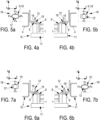
FIG. 4a and FIG. 4b are top views of the respectively left and right ends of a mounting tool according to a first embodiment of the invention. -
FIG. 5a and FIG. 5b are front views of the respectively left and right ends illustrated inFigs 4a and 4b . -
FIG. 6a and FIG. 6b are top views of the respectively left and right ends of a mounting tool according to a second embodiment of the invention. -
FIG. 7a and FIG. 7b are front views of the respectively left and right ends illustrated inFigs 6a and 6b . -
FIG. 8 is an enlarged view of the left end illustrated inFig. 5a in a first mounting position of the tool. -
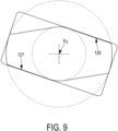
FIG. 9 is an enlarged view of the left end illustrated inFig. 5a in a second mounting position of the tool. -
FIG. 10a and FIG. 10b are top views of the respectively left and right ends of a mounting tool according to a third embodiment of the invention. -
FIG. 11a and FIG. 11b are front perspective views of the respectively left and right ends illustrated inFigs 10a and 10b . -
FIG. 12 is an enlarged front view of the left end illustrated inFig. 11a in a first mounting position of the tool. -
FIG. 13 is an enlarged front view of the left end illustrated inFig. 11a in a second mounting position of the tool. - Aspects set forth below represent the necessary information to enable those skilled in the art to practice the disclosure.
-
FIG. 1 illustrates acrosspiece 1, also known as Cross Truck Beam (CTB), which is suitable for supporting adashboard 2 of acockpit 3, illustrated inFIG. 2 , thedashboard 2 supported by thecross-piece 1 being fixed to the body-in-white (BIW) 4 of acab 5 of an industrial vehicle, as illustrated inFIG. 3 . - The
dashboard 2 may include one or more subset chosen among a heating, ventilating and air-conditioning unit, a control pedals unit, a steering column unit, an electric control unit, and an airbag unit. - The
crosspiece 1 extends along a vehicle transverse direction Y and comprises, at each of its ends, a fixinginterface Fig. 1 , each fixinginterface crosspiece 1 to the body-in-white 4. - Alternatively, the
crosspiece 1 could be fixed on the body-in-white 4 by any means equivalent to bolts, like e.g. welding, rivets, glue areas, clip fixing devices, etc. - As illustrated in
FIG. 4a and FIG. 4b , thecrosspiece 1 and the body-in-white 4 comprises a left mountinginterface 8, respectively 18, and a right mounting interface 8', respectively 18', allowing thecrosspiece 1 to be temporary connected on a mountingtool 10. The left, respectively the right, mountinginterface 8, 8' of thecrosspiece 1 is provided with a left, respectively a right,positioning hole 9, 9', said positioning holes 9, 9' having a substantially rectangular shape in a section plane parallel to the vertical plane, as shown inFIG. 5a and FIG. 5b . Said rectangular shape is defined by a larger dimension along a vehicle transverse direction Y than along a vehicle vertical direction Z. The left, respectively the right, mountinginterface 18, 18' of the body-in-white 4 is provided with a left, respectively a right,positioning hole 19, 19', said positioning holes 19, 19' having the same shape as the positioning holes 9, 9' in a section plane parallel to the vertical plane. - In the embodiment shown in
Figs 4a and 4b , thetool 10 comprises asupport plate 11 extending in a vertical plane, and one left centeringpin 12 and one right centering pin 12' extending in a direction perpendicular to the vertical plane. The centering pins 12, 12' are configured to be respectively inserted into the left, respectively the right, positioning holes 9, 19, 9', 19' formed respectively in thecrosspiece 1 and the body-in-white 4 in a mounting position of thetool 10, illustrated inFigs 4a and 4b . The centering pins 12, 12' may advantageously be provided with a tapered end for optimum engagement into the corresponding positioning holes. - In the embodiment of
Figs 5a and 5b , the right centering pin 12' has a cylindrical shape and is configured to contact thecrosspiece 1, respectively the body-in-white 4, in two points P1, P2 aligned in a vehicle vertical direction in the mounting position of thetool 10, thus preventing a movement of the right centering pin 12' relative to thecrosspiece 1 and the body-in-white 4 along said vehicle vertical direction. In other words, once fitted into the corresponding holes, said right centering pin provides an axial stop along vertical direction. The left centeringpin 12 has an oblong cross-section, e.g. of trapezoid shape that is partially complementary to the shape of theleft positioning holes crosspiece 1, respectively the body-in-white 4, in two points P3, P4 aligned in a vehicle vertical direction and in two points P5, P6 aligned in a vehicle transverse direction in the mounting position of thetool 10, thus preventing a movement of the left centeringpin 12 relative to thecrosspiece 1 and the body-in-white 4 along said vehicle vertical direction and said vehicle transverse direction. This special cross-section is defined by two axes of symmetry that are crossing by the center of the section and that are respectively parallel to the vehicle transverse direction Y and to a vertical axis Z perpendicular to the vehicle longitudinal and transverse directions X, Y and is configured to be circumscribed inside a rectangle. - As illustrated in
FIG. 8 , the left centeringpin 12 is defined by upper and lower curvedperipheral areas peripheral areas peripheral areas left positioning holes peripheral areas left positioning holes peripheral area 121 is linked to the left and right curvedperipheral areas peripheral areas peripheral area 122 is linked to the left and right curvedperipheral areas peripheral areas - As shown in
FIG. 8 , the first and the second circles C1, C2 have the same center X0. Thus configured, thecrosspiece 1 and the body-in-white 4 may thus rotate clockwise relative to the left centeringpin 12 around a longitudinal axis passing through said center X0 to reach a second position shown inFIG. 9 , in which they have pivoted at an angle αmax relative to their position inFig. 8 . In this second position, the upper right planarperipheral area 126 and the lower left planarperipheral area 127 of the centeringpin 12 abut against thecrosspiece 1 and the body-in-white 4. This second mounting position may occur if thecrosspiece 1 and the body-in-white 4 are not straight or sag relative to their ideal mounting position illustrated inFig. 8 . - It is clear that the centering
pin 12 is also adapted to be inserted in theleft positioning holes Fig. 8 and the second position illustrated inFig. 9 . - Moreover, the
crosspiece 1 and the body-in-white 4 may also rotate counterclockwise relative to the left centeringpin 12 around a longitudinal axis passing through the center X0 to reach a third position (not shown), in which they have pivoted at an angle αmax relative to their position inFig. 8 . In this third position, the upper left planarperipheral area 125 and the lower right planarperipheral area 128 abut against thecrosspiece 1 and the body-in-white 4. - It is clear that the centering
pin 12 is also adapted to be inserted in theleft positioning holes Fig. 8 and said third position. - Thus configured, the
tool 10 avoids wear of the centering pins during the insertion of the centering pins in the corresponding positioning holes of thecrosspiece 1 and the body-in-white 4 whatever the positions of thecrosspiece 1 and the body-in-white 4 relative to their ideal mounting position illustrated inFig. 8 . - In a preferred embodiment of the invention, the left centering
pin 12 and the right centering pin 12' may be removably attached to thesupport plate 11. Accordingly, thetool 10 may be easily modified to invert the positions of the left and right centering pins 12, 12', as illustrated inFIG. 6a and FIG. 6b, and FIG. 7a and FIG. 7b . - In this alternative embodiment, the
tool 10 comprises a left centering pin 12' and a right centeringpin 12 extending along a longitudinal direction. The centering pins 12', 12 are configured to be respectively inserted into the left, respectively the right, positioning holes 9, 19, 9', 19' formed respectively in thecrosspiece 1 and the body-in-white 4 in the mounting position of thetool 10, illustrated inFigs 6a and 6b . - As shown in
Figs 7a and 7b , the left centering pin 12' has a cylindrical shape and is configured to contact thecrosspiece 1, respectively the body-in-white 4, in two points P1, P2 aligned in a vehicle vertical direction in the mounting position of thetool 10, thus preventing a movement of the left centering pin 12' relative to thecrosspiece 1 and the body-in-white 4 along said vehicle vertical direction, and theright centering pin 12 has a trapezoid shape that is partially complementary to the shape of the right positioning holes 9', 19' and is configured to contact thecrosspiece 1, respectively the body-in-white 4, in two points P3, P4 aligned in a vehicle vertical direction and in two points P5, P6 aligned in a vehicle transverse direction in the mounting position of thetool 10, thus preventing a movement of theright centering pin 12 relative to thecrosspiece 1 and the body-in-white 4 along said vehicle vertical direction and said vehicle transverse direction. - The
right centering pin 12 having the specific shape shown inFig. 8 , and the right positioning holes 9', 19' of thecrosspiece 1 and of the body-in-white 4 having the same shape as theleft positioning holes crosspiece 1 and the body-in-white 4 may thus rotate clockwise relative to theright centering pin 12 around a longitudinal axis passing through the center X0 to reach a second position, shown inFig. 9 , in which thecrosspiece 1 and the body-in-white 4 have pivoted at an angle αmax relative to their position inFig. 8 , or any intermediate positions between the position illustrated inFig. 8 and this second position. In the same way, thecrosspiece 1 and the body-in-white 4 may also rotate counterclockwise relative to theright centering pin 12 around a longitudinal axis passing through the center X0 to reach a third position (not shown), in which thecrosspiece 1 and the body-in-white 4 have pivoted at an angle αmax relative to their position inFig. 8 , or any intermediate positions between the position illustrated inFig. 8 and this third position. - In a further alternative embodiment illustrated in
FIG. 10a and FIG. 10b , thetool 10 comprises asupport plate 11 extending in a vertical plane, and two sets of spindles, respectively a left set comprising a firstleft spindle 14, a secondleft spindle 15, and a thirdleft spindle 16, and a right set comprising a first right spindle 14', a secondright spindle 15', and a third right spindle 16'. The firstleft spindle 14, respectively the first right spindle 14', is fixedly attached to thesupport plate 11 and the second and thirdleft spindles right spindles 15', 16', are slidably fixed to thesupport plate 11 such that they are movable between a deployed position, shown inFIG. 11a , in which they extend at both sides of a top portion of the firstleft spindle 14, respectively of the first right spindle 14', and a retracted position, shown inFIG. 11b , in which they extend at both sides of a bottom portion of the firstleft spindle 14, respectively of the first right spindle 14'. - In the mounting position of the tool illustrated in
Figs 10a and 10b , the second and thirdleft spindles right spindles 15', 16' are in their retracted position. Thus positioned, the second and thirdleft spindles left positioning holes left mounting interfaces crosspiece 1 and the body-in-white 4, and the second and thirdright spindles 15', 16' are configured to be out of the right positioning holes 9', 19' formed respectively in the right mounting interfaces 8', 18' of thecrosspiece 1 and the body-in-white 4. - As illustrated in
FIG. 12 , the firstleft spindle 14 has a cylindrical shape defined by a peripheral area C1' and a longitudinal axis X1, the diameter D1 of the firstleft spindle 14 corresponding substantially to the dimension L1 of theleft positioning holes crosspiece 1 and the body-in-white 4 in two points P3, P4 aligned in a vehicle vertical direction in the mounting position of thetool 10, thus preventing a movement of the firstleft spindle 14 relative to thecrosspiece 1 and the body-in-white 4 along said vehicle vertical direction. - The second
left spindle 15 has a substantially hemi-cylindrical shape defined by a left curvedperipheral area 151 having, in a sectional vertical plane, a circular arc shape inscribed in a circle C2', said circle C2' having a center X2 and a first radius r2. The thirdleft spindle 16 has a substantially hemi-cylindrical shape defined by a right curvedperipheral area 161 having, in a sectional vertical plane, a circular arc shape inscribed in a circle C3', said circle C3' having a center X3 and a radius r3. - In a specific embodiment, the radius r3 may be equal to the radius r2.
- The second and third
left spindles left positioning holes - Thus configured, the second
left spindle 15 contacts thecrosspiece 1, respectively the body-in-white 4, in one point P5 and the thirdleft spindle 16 contacts thecrosspiece 1, respectively the body-in-white 4, in one point P6, the points P5 and P6 being aligned in a vehicle transverse direction in the mounting position of thetool 10, thus preventing a movement of the second and thirdleft spindles crosspiece 1 and the body-in-white 4 along said vehicle transverse direction. - The
crosspiece 1 and the body-in-white 4 may rotate clockwise relative to the firstleft spindle 14 around the longitudinal axis X1 to reach the position shown inFIG. 13 , in which thecrosspiece 1 and the body-in-white 4 have pivoted at an angle α relative to their position inFig. 12 . In this position, the left curvedperipheral area 151 of the secondleft spindle 15 and the right curvedperipheral area 161 of the thirdleft spindle 16 are no longer in contact with thecrosspiece 1 and the body-in-white 4. - Thus configured, the
tool 10 avoids wear of the spindles during the insertion of the spindles in the corresponding positioning holes of thecrosspiece 1 and the body-in-white 4 whatever the positions of thecrosspiece 1 and the body-in-white 4 relative to their ideal mounting position illustrated inFig. 12 . - It is clear that the embodiment shown in
Figs 10a and 10b may be easily modified by inverting the positions of the second and third left andright spindles left spindles right spindles 15', 16' may be moved in their deployed position. This modified embodiment may be adapted for RHD vehicle. - Regardless of the tool variant used, the method for mounting a
cockpit 3 to a body-in-white 4 of a motor vehicle cab may comprise the following steps: - moving the
tool 10 until the left, respectively right, centeringpin 12, 12', or set of spindles 14-16, 14'-16', is inserted in the left, respectively right,positioning hole 9, 9' of thecrosspiece 1 ; - moving the
tool 10, holding thecrosspiece 1, until the left, respectively right, centeringpin 12, 12', or set of spindles 14-16, 14'-16', is inserted in the left, respectively right,positioning hole 19, 19' of the body-in-white 4 ; - fastening the
crosspiece 1 to the body-in-white 4 ; - moving the
tool 10 along a longitudinal axis until the the left, respectively right, centeringpin 12, 12', or set of spindles 14-16, 14'-16', is out of the left, respectively right, positioning holes 9, 9', 19, 19' of thecrosspiece 1 and of the body-in-white. - The terminology used herein is for the purpose of describing particular aspects only and is not intended to be limiting of the disclosure. As used herein, the singular forms "a," "an," and "the" are intended to include the plural forms as well, unless the context clearly indicates otherwise. As used herein, the term "and/or" includes any and all combinations of one or more of the associated listed items. It will be further understood that the terms "comprises," "comprising," "includes," and/or "including" when used herein specify the presence of stated features, integers, steps, operations, elements, and/or components, but do not preclude the presence or addition of one or more other features, integers, steps, operations, elements, components, and/or groups thereof.
- It will be understood that, although the terms first, second, etc., may be used herein to describe various elements, these elements should not be limited by these terms. These terms are only used to distinguish one element from another. For example, a first element could be termed a second element, and, similarly, a second element could be termed a first element without departing from the scope of the present disclosure.
- Relative terms such as "below" or "above" or "upper" or "lower" or "horizontal" or "vertical" may be used herein to describe a relationship of one element to another element as illustrated in the Figures. It will be understood that these terms and those discussed above are intended to encompass different orientations of the device in addition to the orientation depicted in the Figures. It will be understood that when an element is referred to as being "connected" or "coupled" to another element, it can be directly connected or coupled to the other element, or intervening elements may be present. In contrast, when an element is referred to as being "directly connected" or "directly coupled" to another element, there are no intervening elements present.
- Unless otherwise defined, all terms (including technical and scientific terms) used herein have the same meaning as commonly understood by one of ordinary skill in the art to which this disclosure belongs. It will be further understood that terms used herein should be interpreted as having a meaning consistent with their meaning in the context of this specification and the relevant art and will not be interpreted in an idealized or overly formal sense unless expressly so defined herein.
- It is to be understood that the present disclosure is not limited to the aspects described above and illustrated in the drawings; rather, the skilled person will recognize that many changes and modifications may be made within the scope of the present disclosure and appended claims. In the drawings and specification, there have been disclosed aspects for purposes of illustration only and not for purposes of limitation, the scope of the inventive concepts being set forth in the following claims.
- In particular, the shape of the left and right positioning holes formed in the crosspiece and the body-in-white may vary and may, for example, be oblong or circular.
Claims (17)
1. A tool (10) for mounting a cockpit (3) to a body-in-white (4) of a motor vehicle cab (5), the cockpit (3) comprising a crosspiece (1) extending in a vehicle transverse direction (Y) and a dashboard (2), the tool (10) comprising:
- a support plate (11);
- a left centering pin (12, 12', 14-16) extending in a longitudinal direction (X) perpendicular to the support plate and configured to be inserted into two corresponding left positioning holes (9, 19) formed respectively in the crosspiece (1) and the body-in-white (4) ;
- a right centering pin (12, 12', 14'-16') extending in a direction (X) perpendicular to the support plate and configured to be inserted into two corresponding right positioning holes (9', 19') formed respectively in the crosspiece (1) and the body-in-white (4);
wherein one of the said left centering pin (12, 12', 14-16) and said right centering pin (12, 12', 14'-16') has a circular cross-section and the other of said left centering pin (12, 12', 14-16) and said right centering pin (12, 12', 14'-16') has a special cross-section having its greatest overall dimension parallel to the vehicle transverse direction (Y). 2. The tool (10) of claim 1, wherein the other one of the said left centering pin (12, 12') and of the said right centering pin (12, 12') is defined by upper and lower curved peripheral areas (121, 122) and left and right curved peripheral areas (123, 124), the upper and lower curved peripheral areas (121, 122) having, in a section plane parallel to the vertical plane, a circular arc shape inscribed in a first circle (C1), the diameter (D1) of the first circle (C1) corresponding substantially to the dimension (L1) of the corresponding left or right positioning holes (9, 19; 9', 19') along a vehicle vertical direction (Z), and the left and right curved peripheral areas (123, 124) having, in a section plane parallel to the vertical plane, a circular arc shape inscribed in a second circle (C2), the diameter (D2) of the second circle (C2) corresponding substantially to the dimension (L2) of the corresponding left or right positioning holes (9, 19; 9', 19') along a vehicle transverse direction (Y).
3. The tool (10) of claim 2, wherein the upper, respectively the lower, curved peripheral area (121, 122) is linked to the left, respectively the right, curved peripheral area (123, 124) via a planar peripheral area (125-128).
4. The tool (10) of any of claims 2-3, wherein the first and the second circles (C1, C2) have the same center (X0).
5. The tool (10) of any of claims 1-4, wherein the left centering pin (12, 12') and the right centering pin (12, 12') are removably attached to the support plate (11).
6. The tool (10) of claim 1, wherein the left centering pin or the right centering pin is made of a first, a second and a third parallel spindles (14-16; 14'-16'), wherein the first spindle (14, 14') is fixedly attached to the support plate (11) and the second and third spindles (15,16; 15',16') are slidably fixed to the support plate (11) such that they are movable between a deployed position, in which they extend at both sides of a top portion of the first spindle (14, 14'), and a retracted position, in which they extend at both sides of a bottom portion of the spindle (14, 14').
7. The tool (10) of claim 6, wherein the second and third spindles (15, 16; 15', 16') are configured to be housed into the left or right positioning hole (9, 19; 9', 19') formed respectively in the crosspiece (1) and the body-in-white (4) in the mounting position of the tool and when they are in their deployed position, and to be out of said left or right positioning hole (9, 19; 9', 19') in the mounting position of the tool and when they are in their retracted position.
8. The tool (10) of any of claims 6-7, wherein the first spindle (14, 14') has a cylindrical shape, the diameter (D1) of the first spindle (14, 14') corresponding substantially to the dimension (L1) of the left or right positioning hole (9, 19; 9', 19') along a vehicle vertical direction (Z),
wherein the second spindle (15, 15') is defined by a left curved peripheral area (151) having, in a section plane parallel to the vertical plane, a circular arc shape inscribed in a first circle (C2'), said first circle (C2') having a first center (X2) and a first radius (r2),
wherein the third spindle (16, 16') is defined by a right curved peripheral area (161) having, in a section plane parallel to the vertical plane, a circular arc shape inscribed in a second circle (C3'), said second circle (C3') having a second center (X3) and a second radius (r3), and
wherein the distance (d) between the first and the second centers (X2, X3) is substantially equal to the dimension (L2) of the left or right positioning hole (9, 19; 9', 19') along a vehicle transverse direction (Y) minus the first and second radii (r2, r3).
9. The tool (10) of claim 8, wherein the first and the second circles (C2', C3') have the same radius.
10. The tool (10) of any previous claim, wherein the special cross-section has two axes of symmetry that are crossing by the center of the section and that are respectively parallel to the vehicle transverse direction (Y) and to a vertical axis (Z) perpendicular to the vehicle longitudinal and transverse directions (X, Y).
11. The tool (10) of any previous claim, wherein each of the left and right centering pins (12, 12') or each spindle (14-16; 14'-16') has a tapered end for optimum engagement into the corresponding positioning holes (9, 19; 9', 19').
12. The tool (10) of any previous claim, wherein the special cross-section is such that it can be circumscribed inside a rectangle.
13. A method for mounting a cockpit (3) to a body-in-white (4) of a motor vehicle cab (5), the cockpit (3) comprising a crosspiece (1) extending in a vehicle transverse direction (Y) and a dashboard (2), the crosspiece (1) and the body-in-white (4) being respectively provided with left and right positioning holes (9, 19; 9', 19'), said left and right positioning holes (9, 19; 9', 19') having preferably an oblong shape and being preferably defined by a larger dimension (L2) along a vehicle transverse direction (Y) than along a vehicle vertical direction (Z), the method comprising:
- moving a tool (10) according to any one of claims 1-12 until the left, respectively right, centering pin (12, 12'; 14-16, 14') is inserted in the left, respectively right, positioning hole (9, 19; 9', 19') of the crosspiece (1) ;
- moving the tool (10), holding the crosspiece, until the left, respectively right, centering pin (12, 12'; 14-16, 14') is inserted in the left, respectively right, positioning hole (9, 19; 9', 19') of the body-in-white (4),;
- fastening the crosspiece (1) to the body-in-white (4) ;
- moving the tool (10) along a longitudinal axis (X) until the left, respectively right, centering pin (12, 12'; 14-16, 14') is out of the left, respectively right, positioning holes (9, 19; 9', 19') of the crosspiece (1) and of the body-in-white (4).
13. A motor vehicle cab (5) comprising a body-in-white (4) and a dashboard (2) fixedly connected thereto through a crosspiece (1) extending in a vehicle transverse direction (Y), wherein the crosspiece (1) and the body-in-white (4) each comprises a left mounting interface (8, 18) and a right mounting interface (8', 18'), said left mounting interface (8, 18), respectively said right mounting interface (8', 18'), being provided with a left positioning hole (9, 19), respectively a right positioning hole (9', 19'), said left and right positioning holes (9, 9', 19, 19') having each an oblong shape. 14. The motor vehicle cab (5) of claim 13, wherein the oblong shape of the left and right positioning holes (9, 9', 19, 19') is defined by a larger dimension along the vehicle transverse direction (Y) than along a vehicle vertical direction (Z).
15. The motor vehicle cab (5) of claim 13 or 14, wherein the left and right positioning holes (19, 19') of the body-in-white (4) have the same shape as the left and right positioning holes (9, 9') of the crosspiece (1).
16. The motor vehicle cab (5) of any of claims 13-15, wherein the left and right positioning holes (9, 9', 19, 19') of the crosspiece (1) and of the body-in-white (4) have a substantially rectangular shape in a section plane perpendicular to a vehicle longitudinal direction.
17. A motor vehicle comprising a motor vehicle cab (5) according to any of claims 13-16.
Priority Applications (2)
| Application Number | Priority Date | Filing Date | Title |
|---|---|---|---|
| EP23174007.7A EP4464577A1 (en) | 2023-05-17 | 2023-05-17 | A tool and a method for mounting a cockpit to the body-in-white of a motor vehicle cab |
| US18/659,133 US20240383551A1 (en) | 2023-05-17 | 2024-05-09 | Tool and method for mounting a cockpit to the body-in-white of a motor vehicle cab |
Applications Claiming Priority (1)
| Application Number | Priority Date | Filing Date | Title |
|---|---|---|---|
| EP23174007.7A EP4464577A1 (en) | 2023-05-17 | 2023-05-17 | A tool and a method for mounting a cockpit to the body-in-white of a motor vehicle cab |
Publications (1)
| Publication Number | Publication Date |
|---|---|
| EP4464577A1 true EP4464577A1 (en) | 2024-11-20 |
Family
ID=86386775
Family Applications (1)
| Application Number | Title | Priority Date | Filing Date |
|---|---|---|---|
| EP23174007.7A Pending EP4464577A1 (en) | 2023-05-17 | 2023-05-17 | A tool and a method for mounting a cockpit to the body-in-white of a motor vehicle cab |
Country Status (2)
| Country | Link |
|---|---|
| US (1) | US20240383551A1 (en) |
| EP (1) | EP4464577A1 (en) |
Citations (4)
| Publication number | Priority date | Publication date | Assignee | Title |
|---|---|---|---|---|
| DE19680933T1 (en) * | 1995-10-12 | 1997-10-16 | Scania Cv Ab | Instrument panel and vehicle with an instrument panel |
| US7506433B2 (en) * | 2001-04-27 | 2009-03-24 | Nissan Motor Co., Ltd. | Apparatus and method for installing cockpit module in vehicle body |
| FR2966209A1 (en) * | 2010-10-13 | 2012-04-20 | Peugeot Citroen Automobiles Sa | Method for assembling Roman cage on reinforcement part, involves supporting side surfaces of centering pins against support surfaces of notches and center openings to establish non-specific contact between side and support surfaces |
| US9238493B2 (en) * | 2011-02-03 | 2016-01-19 | Mazda Motor Corporation | Method of installing instrument panel module to vehicle |
-
2023
- 2023-05-17 EP EP23174007.7A patent/EP4464577A1/en active Pending
-
2024
- 2024-05-09 US US18/659,133 patent/US20240383551A1/en active Pending
Patent Citations (4)
| Publication number | Priority date | Publication date | Assignee | Title |
|---|---|---|---|---|
| DE19680933T1 (en) * | 1995-10-12 | 1997-10-16 | Scania Cv Ab | Instrument panel and vehicle with an instrument panel |
| US7506433B2 (en) * | 2001-04-27 | 2009-03-24 | Nissan Motor Co., Ltd. | Apparatus and method for installing cockpit module in vehicle body |
| FR2966209A1 (en) * | 2010-10-13 | 2012-04-20 | Peugeot Citroen Automobiles Sa | Method for assembling Roman cage on reinforcement part, involves supporting side surfaces of centering pins against support surfaces of notches and center openings to establish non-specific contact between side and support surfaces |
| US9238493B2 (en) * | 2011-02-03 | 2016-01-19 | Mazda Motor Corporation | Method of installing instrument panel module to vehicle |
Also Published As
| Publication number | Publication date |
|---|---|
| US20240383551A1 (en) | 2024-11-21 |
Similar Documents
| Publication | Publication Date | Title |
|---|---|---|
| US8146986B2 (en) | Dashboard support, and method of making a dashboard support | |
| US7048325B1 (en) | Adjustable vehicle cross beam | |
| WO2007095198A1 (en) | Height adjustment blocks for leaf spring suspension | |
| US20240034413A1 (en) | Dashboard crossbeam assembly for a vehicle | |
| CN105882734A (en) | Rack bar unit of vehicle steering device | |
| JPH06263040A (en) | Bracket structure for supporting car steering column | |
| US20240383551A1 (en) | Tool and method for mounting a cockpit to the body-in-white of a motor vehicle cab | |
| US7305766B1 (en) | Method for assembling a bus | |
| JP2000016303A (en) | Steering device | |
| US20170291631A1 (en) | Column housing for vehicle steering system | |
| US11643039B2 (en) | Instrument panel | |
| CN112519923A (en) | Assembling method of mounting seat on front shock absorber and initial blank of mounting seat on front shock absorber | |
| US9950745B2 (en) | Cockpit cross beam with variable steering column angle of inclination | |
| US11591004B2 (en) | Bracket and steering apparatus | |
| US12286147B2 (en) | Steering device | |
| JP2017132441A (en) | Vehicle case fixing unit and substrate housing case | |
| JP2010137846A (en) | Automobile equipped with air guide apparatus, and method of mounting the air guide apparatus | |
| JP3743937B2 (en) | Modeling method of steering system for automobile | |
| JP2003341340A (en) | Air conditioning duct structure for vehicles | |
| CN205916202U (en) | A device for being directed at vehicle dashboard crossbeam advances line location | |
| US20210197670A1 (en) | Instrument panel structure | |
| US20250100625A1 (en) | Vehicle body front structure | |
| CN108778915B (en) | Instrument panel preparation tool | |
| CN121316984A (en) | A left- or right-hand drive interchangeable instrument frame, instrument panel assembly and vehicle | |
| CN219969557U (en) | Vehicle-mounted radar adjusting device, adjusting system and vehicle |
Legal Events
| Date | Code | Title | Description |
|---|---|---|---|
| PUAI | Public reference made under article 153(3) epc to a published international application that has entered the european phase |
Free format text: ORIGINAL CODE: 0009012 |
|
| STAA | Information on the status of an ep patent application or granted ep patent |
Free format text: STATUS: THE APPLICATION HAS BEEN PUBLISHED |
|
| AK | Designated contracting states |
Kind code of ref document: A1 Designated state(s): AL AT BE BG CH CY CZ DE DK EE ES FI FR GB GR HR HU IE IS IT LI LT LU LV MC ME MK MT NL NO PL PT RO RS SE SI SK SM TR |
|
| STAA | Information on the status of an ep patent application or granted ep patent |
Free format text: STATUS: REQUEST FOR EXAMINATION WAS MADE |
|
| 17P | Request for examination filed |
Effective date: 20250206 |