EP4464565A1 - Switching control method for hybrid vehicle, vehicle controller, and hybrid vehicle - Google Patents
Switching control method for hybrid vehicle, vehicle controller, and hybrid vehicle Download PDFInfo
- Publication number
- EP4464565A1 EP4464565A1 EP23737126.5A EP23737126A EP4464565A1 EP 4464565 A1 EP4464565 A1 EP 4464565A1 EP 23737126 A EP23737126 A EP 23737126A EP 4464565 A1 EP4464565 A1 EP 4464565A1
- Authority
- EP
- European Patent Office
- Prior art keywords
- hybrid
- power vehicle
- switching
- operating modes
- target operating
- Prior art date
- Legal status (The legal status is an assumption and is not a legal conclusion. Google has not performed a legal analysis and makes no representation as to the accuracy of the status listed.)
- Pending
Links
Images


Classifications
-
- B—PERFORMING OPERATIONS; TRANSPORTING
- B60—VEHICLES IN GENERAL
- B60W—CONJOINT CONTROL OF VEHICLE SUB-UNITS OF DIFFERENT TYPE OR DIFFERENT FUNCTION; CONTROL SYSTEMS SPECIALLY ADAPTED FOR HYBRID VEHICLES; ROAD VEHICLE DRIVE CONTROL SYSTEMS FOR PURPOSES NOT RELATED TO THE CONTROL OF A PARTICULAR SUB-UNIT
- B60W20/00—Control systems specially adapted for hybrid vehicles
- B60W20/20—Control strategies involving selection of hybrid configuration, e.g. selection between series or parallel configuration
-
- B—PERFORMING OPERATIONS; TRANSPORTING
- B60—VEHICLES IN GENERAL
- B60W—CONJOINT CONTROL OF VEHICLE SUB-UNITS OF DIFFERENT TYPE OR DIFFERENT FUNCTION; CONTROL SYSTEMS SPECIALLY ADAPTED FOR HYBRID VEHICLES; ROAD VEHICLE DRIVE CONTROL SYSTEMS FOR PURPOSES NOT RELATED TO THE CONTROL OF A PARTICULAR SUB-UNIT
- B60W10/00—Conjoint control of vehicle sub-units of different type or different function
- B60W10/04—Conjoint control of vehicle sub-units of different type or different function including control of propulsion units
- B60W10/06—Conjoint control of vehicle sub-units of different type or different function including control of propulsion units including control of combustion engines
-
- B—PERFORMING OPERATIONS; TRANSPORTING
- B60—VEHICLES IN GENERAL
- B60W—CONJOINT CONTROL OF VEHICLE SUB-UNITS OF DIFFERENT TYPE OR DIFFERENT FUNCTION; CONTROL SYSTEMS SPECIALLY ADAPTED FOR HYBRID VEHICLES; ROAD VEHICLE DRIVE CONTROL SYSTEMS FOR PURPOSES NOT RELATED TO THE CONTROL OF A PARTICULAR SUB-UNIT
- B60W10/00—Conjoint control of vehicle sub-units of different type or different function
- B60W10/04—Conjoint control of vehicle sub-units of different type or different function including control of propulsion units
- B60W10/08—Conjoint control of vehicle sub-units of different type or different function including control of propulsion units including control of electric propulsion units, e.g. motors or generators
-
- B—PERFORMING OPERATIONS; TRANSPORTING
- B60—VEHICLES IN GENERAL
- B60W—CONJOINT CONTROL OF VEHICLE SUB-UNITS OF DIFFERENT TYPE OR DIFFERENT FUNCTION; CONTROL SYSTEMS SPECIALLY ADAPTED FOR HYBRID VEHICLES; ROAD VEHICLE DRIVE CONTROL SYSTEMS FOR PURPOSES NOT RELATED TO THE CONTROL OF A PARTICULAR SUB-UNIT
- B60W20/00—Control systems specially adapted for hybrid vehicles
- B60W20/10—Controlling the power contribution of each of the prime movers to meet required power demand
-
- B—PERFORMING OPERATIONS; TRANSPORTING
- B60—VEHICLES IN GENERAL
- B60W—CONJOINT CONTROL OF VEHICLE SUB-UNITS OF DIFFERENT TYPE OR DIFFERENT FUNCTION; CONTROL SYSTEMS SPECIALLY ADAPTED FOR HYBRID VEHICLES; ROAD VEHICLE DRIVE CONTROL SYSTEMS FOR PURPOSES NOT RELATED TO THE CONTROL OF A PARTICULAR SUB-UNIT
- B60W20/00—Control systems specially adapted for hybrid vehicles
- B60W20/40—Controlling the engagement or disengagement of prime movers, e.g. for transition between prime movers
-
- Y—GENERAL TAGGING OF NEW TECHNOLOGICAL DEVELOPMENTS; GENERAL TAGGING OF CROSS-SECTIONAL TECHNOLOGIES SPANNING OVER SEVERAL SECTIONS OF THE IPC; TECHNICAL SUBJECTS COVERED BY FORMER USPC CROSS-REFERENCE ART COLLECTIONS [XRACs] AND DIGESTS
- Y02—TECHNOLOGIES OR APPLICATIONS FOR MITIGATION OR ADAPTATION AGAINST CLIMATE CHANGE
- Y02T—CLIMATE CHANGE MITIGATION TECHNOLOGIES RELATED TO TRANSPORTATION
- Y02T10/00—Road transport of goods or passengers
- Y02T10/60—Other road transportation technologies with climate change mitigation effect
- Y02T10/62—Hybrid vehicles
Definitions
- the present application relates to the technical field of vehicle controlling and, more particularly, relates to a switching controlling method for a hybrid-power vehicle, an entire-vehicle controller and the hybrid-power vehicle.
- hybrid-power vehicles refer to hybrid vehicles.
- the driving system of a hybrid-power vehicle consists of two or more power units that can operate independently.
- Oil-electricity hybrid-power vehicles Hybrid Electric Vehicles
- Hybrid Electric Vehicles are a typical type of hybrid-power vehicles.
- An object of the present application is to provide a switching controlling method for a hybrid-power vehicle, an entire-vehicle controller and the hybrid-power vehicle, to reduce the problems in the drivability caused by frequent mode switching.
- a switching controlling method for a hybrid-power vehicle includes:
- the step of detecting in real time the switching frequency that the hybrid-power vehicle switches between the at least two target operating modes includes:
- a time span of the latest time period is T; and when a current moment is t, a starting moment of the latest time period is t-T, and an ending moment is t.
- the step of detecting in real time the switching frequency that the hybrid-power vehicle switches between the at least two target operating modes includes:
- the preset time quantity N 3.
- the step of updating the condition parameter according to the switching frequency includes:
- a quantity of the switching-mode level is 3, and the switching-mode level is divided into level 1, level 2 and level 3.
- condition parameter includes a reserved torque of an engine of the hybrid-power vehicle; and the reserved torque of the engine of the hybrid-power vehicle is positively correlated with the switching frequency.
- condition parameter includes a delay duration when the hybrid-power vehicle switches between the at least two target operating modes; and the delay duration is positively correlated with the switching frequency.
- the at least two target operating modes include a series-connection mode; and that the hybrid-power vehicle operates in the series-connection mode indicates that an engine of the hybrid-power vehicle outputs an electricity-generation torque, and an electric motor of the hybrid-power vehicle supplies a driving torque.
- the at least two target operating modes include a parallel-connection mode; and that the hybrid-power vehicle operates in the parallel-connection mode indicates that both of an engine and an electric motor of the hybrid-power vehicle output driving torques.
- an entire-vehicle controller including a memory, a processor and a computer program that is stored in the memory and executable in the processor, the processor, when executing the computer program, implements the above steps of switching controlling method for the hybrid-power vehicle.
- a computer-readable storage medium is further provided, the computer-readable storage medium storing a computer program, the computer program, when executed by a processor, implements the above steps of switching controlling method for the hybrid-power vehicle.
- a hybrid-power vehicle is further provided, the hybrid-power vehicle includes the above entire-vehicle controller.
- the advantageous effects of the switching controlling method for the hybrid-power vehicle, the entire-vehicle controller and the hybrid-power vehicle according to the present disclosure are as follows: in order to solve the problems in the drivability caused by frequent mode switching, in the present application, when the switching frequency that the hybrid-power vehicle switches between the target operating modes is greater than the preset frequency, a condition parameter when the hybrid-power vehicle switches between the target operating modes is updated according to the switching frequency, so as to reduce the switching frequency that the hybrid-power vehicle switches between the target operating modes, thereby the problems in the drivability caused by frequent mode switching are reduced.
- the present application by self-adaptive adjustment of the condition parameter, can support the switching controlling of the hybrid-power vehicle under the plurality of switching frequencies.
- the controlling method provided by the present application is not only flexible in control, but also has an extensive application range.
- FIG. 1 is a schematic flow chart of a switching controlling method for a hybrid-power vehicle according to an embodiment of the present application.
- the switching controlling method for the hybrid-power vehicle includes the following steps:
- the target operating modes refer to the operation modes of the hybrid-power vehicle.
- the target operating modes include two modes of a mode A and a mode B
- the switching between the target operating modes of the hybrid-power vehicle refers to that the hybrid-power vehicle switches from the mode A to the mode B, or that the hybrid-power vehicle switches from the mode B to the mode A.
- the switching between the target operating modes of the hybrid-power vehicle refers to that the hybrid-power vehicle switches from the mode A to the mode B, or that the hybrid-power vehicle switches from the mode B to the mode A, or that the hybrid-power vehicle switches from the mode A to the mode C, or that the hybrid-power vehicle switches from the mode C to the mode A, or that the hybrid-power vehicle switches from the mode B to the mode C, or that the hybrid-power vehicle switches from the mode C to the mode B.
- the target operating modes include more modes, the cases are similar to the above examples, and are not discussed further herein.
- the switching frequency that the hybrid-power vehicle switches between the target operating modes is detected in real time, the condition parameter of the hybrid-power vehicle is determined according to the switching frequency, and subsequently according to the condition parameter, it is determined whether to switch the operation mode. Specifically, when the switching frequency is greater than the preset frequency, the condition parameter of the hybrid-power vehicle may be updated according to the switching frequency. When the switching frequency is not greater than the preset frequency, a default condition parameter of the hybrid-power vehicle that is preset may be used, i.e., not updating the condition parameter.
- condition parameter refers to a parameter that is involved in condition determination performed when the hybrid-power vehicle switches between the target operating modes.
- the condition parameter can influence the switching time that the hybrid-power vehicle switches between the target operating modes.
- the step of detecting in real time the switching frequency that the hybrid-power vehicle switches between the at least two target operating modes may include the following steps: detecting in real time the switching time quantity (number of times) that the hybrid-power switches vehicle between the at least two target operating modes within the latest time period, and according to the switching time quantity, determining the switching frequency that the hybrid-power switches between the target operating modes.
- the duration of the latest time period may be constant; for example, it may be T.
- the time quantity i.e., the switching time quantity
- the switching frequency that the hybrid-power vehicle switches between the target operating modes is determined according to the switching time quantity, or the switching time quantity may also be directly used as a characterizing quantity of the switching frequency that the hybrid-power vehicle switches between the target operating modes.
- the step of detecting in real time the switching frequency the hybrid-power vehicle switches between the at least two target operating modes may include the following steps: detecting in real time the duration spent by the hybrid-power vehicle when performing the latest N times of the switching between the target operating modes, wherein N is a preset time quantity; and according to the duration spent by the hybrid-power vehicle when performing the latest N times of the switching, determining the switching frequency that the hybrid-power vehicle switches between the target operating modes.
- the duration spent by the hybrid-power vehicle when performing the latest N times of the switching between the target operating modes is detected. Subsequently, the switching frequency that the hybrid-power vehicle switches between the target operating modes is determined according to the duration, or the duration is directly used as a characterizing quantity of the switching frequency that the hybrid-power vehicle switches between the target operating modes.
- the step of updating the condition parameter according to the switching frequency may include the following steps:
- the switching frequencies of different magnitudes correspond to the switching-mode levels of different magnitudes.
- the updating amount, or, in other words, the adjustment amount, of the condition parameter is not the same.
- the three durations (A, B and C, wherein A ⁇ B ⁇ C) spent by hybrid-power vehicles when performing the latest N times of the switching and three switching-mode levels (level 1, level 2 and level 3) may be set, and it is assumed that, within a time period Ts, the hybrid-power vehicles switch N times between the target operating modes. Based on the above conditions:
- FIG. 2 provides another example.
- the "non-activated” corresponds to before the mode switching
- the “activated” corresponds to after the mode switching.
- condition parameter may include a reserved torque of the engine of the hybrid-power vehicle.
- the reserved torque of the engine of the hybrid-power vehicle is positively correlated with the switching frequency.
- the switching frequency is greater, the reserved torque of the engine of the hybrid-power vehicle is greater. This can ensure that, after the hybrid-power vehicle has performed the switching between the target operating modes (for example, after the hybrid-power vehicle has switched from a series-connection mode to a parallel-connection mode), the power-assistance capacity of the driving electric motor covers a larger torque range, thereby the operation conditions requiring a larger torque that might happen are satisfied. Moreover, if the reserved torque is greater, it is more difficult for the switching between the target operating modes to happen, thereby the switching frequency of the target operating modes is effectively reduced, the problems in the drivability caused by frequent mode switching are reduced.
- FIG. 3 shows the magnitudes of the reserved torque of the engine under the different switching-mode levels (corresponding to the different switching frequencies). It can be known from FIG. 3 that, if the switching frequency is greater, the reserved torque of the engine is greater, the torque range of the engine is also greater. At this moment, it is more difficult for the switching between the target operating modes to happen (for example, the hybrid-power vehicle switches from a series-connection mode to a parallel-connection mode), thereby reducing of the switching frequency is realized.
- condition parameter may include a delay duration when the hybrid-power vehicle switches between the target operating modes.
- the delay duration when the hybrid-power vehicle switches between the target operating modes is positively correlated with the switching frequency.
- the delay duration when the hybrid-power vehicle switches between the target operating modes is longer, which can effectively reduce the switching frequency that the hybrid-power vehicle switches between the target operating modes, to reduce the problems in the drivability caused by frequent mode switching.
- FIG. 4 shows the delay durations (wherein T0, T1, T2 and T3 correspond to level 0, level 1, level 2 and level 3, respectively) when the hybrid-power vehicle switches between the target operating modes under the different switching-mode levels (corresponding to the different switching frequencies). It can be known from FIG. 4 that, if the switching frequency is greater, the delay duration when the hybrid-power vehicle switches between the target operating modes is longer. In the preceding embodiment, a sufficient torque is reserved for the entire vehicle, to prevent false triggering.
- the delay duration when the hybrid-power vehicle switches between the target operating modes is determined according to the switching-mode level.
- the delay duration when the other conditions for the switching between the target operating modes is satisfied, it is further required to reach the delay duration, before the hybrid-power vehicle is controlled to perform the action of the switching between the target operating modes. In this way, false triggering can be prevented from appearing to a large extent, thereby the frequency of the mode switching is reduced to ensure a stable driving environment.
- the target operating modes are a series-connection mode and a parallel-connection mode.
- That the hybrid-power vehicle operates in the series-connection mode indicates that the engine of the hybrid-power vehicle outputs an electricity-generation torque, and the electric motor of the hybrid-power vehicle supplies a driving torque. That the hybrid-power vehicle operates in the parallel-connection mode indicates that both of the engine and the electric motor of the hybrid-power vehicle output driving torques.
- an entire-vehicle controller 500 is provided in the second aspect of the present application, wherein the entire-vehicle controller 500 includes one or more processors 501, one or more inputting devices 502, one or more outputting devices 503 and one or more memories 504.
- the processors 501, the inputting devices 502, the outputting devices 503 and the memories 504 realize the communication therebetween via a communication bus 505.
- the memory 504 is configured to store a computer program, and the computer program includes a program instruction.
- the processor 501 is configured to execute the program instruction stored in the memory 504.
- the processor 501 is configured to be capable of invoking the above program instruction, to execute the steps of the methods in the embodiments of the present application.
- the processor 501 may be a central processing unit (CPU).
- the processors 501 may also be another generic processor, digital signal processor (DSP), application specific integrated circuit (ASIC), field-programmable gate array (FPGA) or another programmable logic device, discrete gate or transistor logic device, discrete hardware assembly and so on.
- the generic processor may be a microprocessor or any other conventional processor.
- the inputting device 502 may include a touchpad, a fingerprint collecting sensor (for collecting the fingerprint information and the fingerprint-direction information of the user), a microphone and so on.
- the outputting device 503 may include a display (an LCD and so on), a loudspeaker and so on.
- the memory 504 may include a read-only memory and a random access memory, and provide instructions and data to the processor 501.
- a part of the memory 504 may further include a non-volatile random access memory.
- the memory 504 may further store the information of the device type.
- the processors 501, the inputting devices 502 and the outputting devices 503 according to the embodiments of the present application may execute the method steps according to the implementations of the switching controlling method for the hybrid-power vehicle according to the present application.
- a computer-readable storage medium stores a computer program, wherein the computer program includes a program instruction, the program instruction, when executed by a processor, implements all or some of the steps according to the embodiments of the switching controlling method for the hybrid-power vehicle stated above. These steps may also be implemented by relative hardware under control by a computer program.
- the computer program includes a computer program code, and the computer program code may be a source code, an object code, an executable file, some intermediate forms, and so on.
- the computer-readable medium may include any entity or device that can carry the computer program code, including a recording medium, a USB flash disk, a mobile hard disk drive, a diskette, an optical disk, a computer memory, a ROM (read-only memory), a RAM (random access memory), an electric carrier signal, a telecommunication signal, a software distribution medium and so on. It should also be noted that the contents included by the computer-readable medium may be properly added or removed according to the requirements by the legislation and the patent practices within jurisdictions. For example, within certain jurisdictions, according to the legislation and the patent practices, the computer-readable medium does not include an electric carrier signal and a telecommunication signal.
- the computer-readable storage medium may be an internal storage unit of the entire-vehicle controller, for example, a hard disk or an internal memory of the entire-vehicle controller.
- the computer-readable storage medium may also be an external storage device of the entire-vehicle controller, for example, a plug-connected hard disk, a smart media card (SMC), a secure digital (SD) card, a flash card, and so on, that the entire-vehicle controller is equipped with.
- the computer-readable storage medium may also include not only the internal storage unit of the entire-vehicle controller, but also the external storage device.
- the computer-readable storage medium is configured to store the computer program, and other programs and data that are required by the entire-vehicle controller.
- the computer-readable storage medium may also be configured to temporarily store the data that have already been outputted or will be outputted.
- controller and method may be implemented in other manners.
- the above-described controller embodiments are merely illustrative.
- the division between the units is merely a division in the logic functions, and in the practical implementation there may be another mode of division.
- multiple units or components may be combined or may be integrated into another system, or some of the features may be omitted, or not implemented.
- the coupling or direct coupling or communicative connection between the illustrated or discussed components may be via the indirect coupling or communicative connection between interfaces or units, and may also be electric, mechanical or in other forms.
- the units that are described as separate components may or may not be physically separate.
- the components that are displayed as units may or may not be physical units. In other words, the components may be located at the same one location, and may also be distributed to a plurality of network units. Some or all of the units may be selected according to practical demands to realize the purposes of the solutions of the embodiments of the present application.
- the functional units according to the embodiments of the present application may be integrated into one processing unit, or the units may also separately physically exist, or two or more of the units may also be integrated into one unit.
- the above-described integrated unit may be embodied in the form of hardware, and may also be embodied in the form of a software function unit.
- a hybrid-power vehicle is provided in the fourth aspect of the present application, wherein the hybrid-power vehicle includes the entire-vehicle controller stated above.
Landscapes
- Engineering & Computer Science (AREA)
- Transportation (AREA)
- Mechanical Engineering (AREA)
- Chemical & Material Sciences (AREA)
- Combustion & Propulsion (AREA)
- Automation & Control Theory (AREA)
- Electric Propulsion And Braking For Vehicles (AREA)
- Hybrid Electric Vehicles (AREA)
Abstract
Description
- The present patent application claims the priority of the Chinese patent application filed on January 7th, 2022 with the application number of No.
CN 202210018308.3 - The present application relates to the technical field of vehicle controlling and, more particularly, relates to a switching controlling method for a hybrid-power vehicle, an entire-vehicle controller and the hybrid-power vehicle.
- When a driver is driving a vehicle, sometimes he performs frequent switching between acceleration and deceleration, at this moment, a phenomenon that the entire-vehicle mode might be switched frequently may appear. In the mode switching, the allocation of the power torques might not be smooth. Therefore, when the entire-vehicle mode is frequently switched, the phenomenon of unsmoothness of the entire-vehicle torques may be abnormally obviously expressed. This problem is especially obvious in hybrid-power vehicles.
- The hybrid-power vehicles refer to hybrid vehicles. The driving system of a hybrid-power vehicle consists of two or more power units that can operate independently. Oil-electricity hybrid-power vehicles (Hybrid Electric Vehicles) are a typical type of hybrid-power vehicles.
- An object of the present application is to provide a switching controlling method for a hybrid-power vehicle, an entire-vehicle controller and the hybrid-power vehicle, to reduce the problems in the drivability caused by frequent mode switching.
- In order to achieve the above object, in a first aspect of the present application, a switching controlling method for a hybrid-power vehicle is provided, wherein the method includes:
- detecting in real time a switching frequency that the hybrid-power vehicle switches between at least two target operating modes;
- when the switching frequency is greater than a preset frequency, updating a condition parameter according to the switching frequency, wherein the condition parameter is a basis for determining whether to switch between the at least two target operating modes; and
- based on the condition parameter that has been updated, determining whether to switch between the at least two target operating modes.
- In a possible embodiment, the step of detecting in real time the switching frequency that the hybrid-power vehicle switches between the at least two target operating modes includes:
- detecting in real time a switching time quantity that the hybrid-power vehicle switches between the at least two target operating modes within a latest time period; and
- according to the switching time quantity, determining the switching frequency that the hybrid-power vehicle switches between the at least two target operating modes.
- In a possible embodiment, a time span of the latest time period is T; and when a current moment is t, a starting moment of the latest time period is t-T, and an ending moment is t.
- In a possible embodiment, the step of detecting in real time the switching frequency that the hybrid-power vehicle switches between the at least two target operating modes includes:
- detecting in real time a first duration spent by the hybrid-power vehicle when performing latest N times of switching between the at least two target operating modes, wherein N is a preset time quantity; and
- according to the first duration, determining the switching frequency that the hybrid-power vehicle switches between the at least two target operating modes.
- In a possible embodiment, the preset time quantity N=3.
- In a possible embodiment, the step of updating the condition parameter according to the switching frequency includes:
- according to the switching frequency, determining a switching-mode level of the hybrid-power vehicle; and
- based on the switching-mode level, updating the condition parameter.
- In a possible embodiment, a quantity of the switching-mode level is 3, and the switching-mode level is divided into
level 1,level 2 andlevel 3. - In a possible embodiment, the condition parameter includes a reserved torque of an engine of the hybrid-power vehicle; and
the reserved torque of the engine of the hybrid-power vehicle is positively correlated with the switching frequency. - In a possible embodiment, the condition parameter includes a delay duration when the hybrid-power vehicle switches between the at least two target operating modes; and
the delay duration is positively correlated with the switching frequency. - In a possible embodiment, the at least two target operating modes include a series-connection mode; and
that the hybrid-power vehicle operates in the series-connection mode indicates that an engine of the hybrid-power vehicle outputs an electricity-generation torque, and an electric motor of the hybrid-power vehicle supplies a driving torque. - In a possible embodiment, the at least two target operating modes include a parallel-connection mode; and that the hybrid-power vehicle operates in the parallel-connection mode indicates that both of an engine and an electric motor of the hybrid-power vehicle output driving torques.
- In a second aspect of the present application, an entire-vehicle controller is further provided, including a memory, a processor and a computer program that is stored in the memory and executable in the processor, the processor, when executing the computer program, implements the above steps of switching controlling method for the hybrid-power vehicle.
- In a third aspect of the present application, a computer-readable storage medium is further provided, the computer-readable storage medium storing a computer program, the computer program, when executed by a processor, implements the above steps of switching controlling method for the hybrid-power vehicle.
- In a fourth aspect of the present application, a hybrid-power vehicle is further provided, the hybrid-power vehicle includes the above entire-vehicle controller.
- The advantageous effects of the switching controlling method for the hybrid-power vehicle, the entire-vehicle controller and the hybrid-power vehicle according to the present disclosure are as follows:
in order to solve the problems in the drivability caused by frequent mode switching, in the present application, when the switching frequency that the hybrid-power vehicle switches between the target operating modes is greater than the preset frequency, a condition parameter when the hybrid-power vehicle switches between the target operating modes is updated according to the switching frequency, so as to reduce the switching frequency that the hybrid-power vehicle switches between the target operating modes, thereby the problems in the drivability caused by frequent mode switching are reduced. In addition, the present application, by self-adaptive adjustment of the condition parameter, can support the switching controlling of the hybrid-power vehicle under the plurality of switching frequencies. The controlling method provided by the present application is not only flexible in control, but also has an extensive application range. - In order to more clearly illustrate the technical solutions of the embodiments of the present application, the figures that are required to be used to describe the embodiments or the related art will be briefly described below. Apparently, the figures that are described below are only some embodiments of the present application, and a person skilled in the art can obtain other figures according to these figures without paying creative work.
-
FIG. 1 is a schematic flow chart of a switching controlling method for a hybrid-power vehicle according to an embodiment of the present application; -
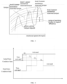
FIG. 2 is a schematic diagram of the correspondence between the switching-mode level and the durations spent by the hybrid-power vehicle when performing latest N times of switching between the target operating modes according to an embodiment of the present application; -
FIG. 3 is a schematic diagram of the correspondence between the switching-mode level and the torques of the engine according to an embodiment of the present application; -
FIG. 4 is a schematic diagram of the correspondence between the switching-mode level and the delay durations when the hybrid-power vehicle switches between the target operating modes according to an embodiment of the present application; and -
FIG. 5 is a schematic structural diagram of an entire-vehicle controller according to an embodiment of the present application. - In order to make the technical problem to be solved, the technical solutions and the advantageous effects of the present application clearer, the present application will be described in further detail below with reference to the drawings and the embodiments. It should be understood that the specific embodiments described herein are merely intended to interpret the present application, and are not intended to limit the present application.
- The present application will be described in further detail below with reference to the drawings and the specific embodiments.
- Referring to
FIG. 1, FIG. 1 is a schematic flow chart of a switching controlling method for a hybrid-power vehicle according to an embodiment of the present application. The switching controlling method for the hybrid-power vehicle includes the following steps: - S101: detecting in real time a switching frequency that the hybrid-power vehicle switches between at least two target operating modes;
- S102: when the switching frequency is greater than a preset frequency, updating a condition parameter according to the switching frequency, wherein the condition parameter is a basis for determining whether to switch between the at least two target operating modes; and
- S103: based on the condition parameter that has been updated, determining whether to switch between the at least two target operating modes.
- In the present embodiment, the target operating modes refer to the operation modes of the hybrid-power vehicle. Exemplarily, when the target operating modes include two modes of a mode A and a mode B, the switching between the target operating modes of the hybrid-power vehicle refers to that the hybrid-power vehicle switches from the mode A to the mode B, or that the hybrid-power vehicle switches from the mode B to the mode A. When the target operating modes include three modes of a mode A, a mode B and a mode C, the switching between the target operating modes of the hybrid-power vehicle refers to that the hybrid-power vehicle switches from the mode A to the mode B, or that the hybrid-power vehicle switches from the mode B to the mode A, or that the hybrid-power vehicle switches from the mode A to the mode C, or that the hybrid-power vehicle switches from the mode C to the mode A, or that the hybrid-power vehicle switches from the mode B to the mode C, or that the hybrid-power vehicle switches from the mode C to the mode B. When the target operating modes include more modes, the cases are similar to the above examples, and are not discussed further herein.
- In the present embodiment, the switching frequency that the hybrid-power vehicle switches between the target operating modes is detected in real time, the condition parameter of the hybrid-power vehicle is determined according to the switching frequency, and subsequently according to the condition parameter, it is determined whether to switch the operation mode. Specifically, when the switching frequency is greater than the preset frequency, the condition parameter of the hybrid-power vehicle may be updated according to the switching frequency. When the switching frequency is not greater than the preset frequency, a default condition parameter of the hybrid-power vehicle that is preset may be used, i.e., not updating the condition parameter.
- In the present embodiment, the condition parameter refers to a parameter that is involved in condition determination performed when the hybrid-power vehicle switches between the target operating modes. The condition parameter can influence the switching time that the hybrid-power vehicle switches between the target operating modes.
- In a possible embodiment, the step of detecting in real time the switching frequency that the hybrid-power vehicle switches between the at least two target operating modes may include the following steps:
detecting in real time the switching time quantity (number of times) that the hybrid-power switches vehicle between the at least two target operating modes within the latest time period, and according to the switching time quantity, determining the switching frequency that the hybrid-power switches between the target operating modes. - In the present embodiment, the duration of the latest time period may be constant; for example, it may be T. In the present embodiment, when the current moment is t, the time quantity (i.e., the switching time quantity) that the hybrid-power vehicle switches between the target operating modes within the time period (t-T)~t may be detected in real time. Subsequently, the switching frequency that the hybrid-power vehicle switches between the target operating modes is determined according to the switching time quantity, or the switching time quantity may also be directly used as a characterizing quantity of the switching frequency that the hybrid-power vehicle switches between the target operating modes.
- In a possible embodiment, the step of detecting in real time the switching frequency the hybrid-power vehicle switches between the at least two target operating modes may include the following steps:
detecting in real time the duration spent by the hybrid-power vehicle when performing the latest N times of the switching between the target operating modes, wherein N is a preset time quantity; and according to the duration spent by the hybrid-power vehicle when performing the latest N times of the switching, determining the switching frequency that the hybrid-power vehicle switches between the target operating modes. - In the present embodiment, the duration spent by the hybrid-power vehicle when performing the latest N times of the switching between the target operating modes is detected. Subsequently, the switching frequency that the hybrid-power vehicle switches between the target operating modes is determined according to the duration, or the duration is directly used as a characterizing quantity of the switching frequency that the hybrid-power vehicle switches between the target operating modes.
- In a possible embodiment, the step of updating the condition parameter according to the switching frequency may include the following steps:
- according to the switching frequency, determining a switching-mode level of the hybrid-power vehicle; and
- based on the switching-mode level, updating the condition parameter.
- In the present embodiment, the switching frequencies of different magnitudes correspond to the switching-mode levels of different magnitudes. For different switching-mode levels, the updating amount, or, in other words, the adjustment amount, of the condition parameter is not the same.
- The solution according to the present embodiment will be described below with examples. For example, the three durations (A, B and C, wherein A<B<C) spent by hybrid-power vehicles when performing the latest N times of the switching and three switching-mode levels (
level 1,level 2 and level 3) may be set, and it is assumed that, within a time period Ts, the hybrid-power vehicles switch N times between the target operating modes. Based on the above conditions: - if Ts ∈ (0,A], then it is determined that the switching-mode level is the
level 3; - if Ts ∈ (A,B], then it is determined that the switching-mode level is the
level 2; - if Ts ∈ (B,C], then it is determined that the switching-mode level is the
level 1; and - if Ts ∈ (C,+∞], then it is determined that the switching-mode level is the
level 0. -
FIG. 2 provides another example. InFIG. 2 , the "non-activated" corresponds to before the mode switching, and the "activated" corresponds to after the mode switching.FIG. 2 takes the case as an example in which the hybrid-power vehicles switch between the target operating modes for three times (in other words, N=3, and the Ts durations are based on the lengths illustrated in the figure), then it is obtained that a ∈ (B,C], b ∈ (A,B], c/d ∈ (0,A], and e ∈ (C,+∞]. In other words, if the switching frequency is higher, the switching-mode level is higher. - In a possible embodiment, the condition parameter may include a reserved torque of the engine of the hybrid-power vehicle.
- The reserved torque of the engine of the hybrid-power vehicle is positively correlated with the switching frequency.
- In the present embodiment, if the switching frequency is greater, the reserved torque of the engine of the hybrid-power vehicle is greater. This can ensure that, after the hybrid-power vehicle has performed the switching between the target operating modes (for example, after the hybrid-power vehicle has switched from a series-connection mode to a parallel-connection mode), the power-assistance capacity of the driving electric motor covers a larger torque range, thereby the operation conditions requiring a larger torque that might happen are satisfied. Moreover, if the reserved torque is greater, it is more difficult for the switching between the target operating modes to happen, thereby the switching frequency of the target operating modes is effectively reduced, the problems in the drivability caused by frequent mode switching are reduced.
- The present embodiment may be comprehended with reference to the above-described switching-mode level and reserved torque. Referring to
FIG. 3, FIG. 3 shows the magnitudes of the reserved torque of the engine under the different switching-mode levels (corresponding to the different switching frequencies). It can be known fromFIG. 3 that, if the switching frequency is greater, the reserved torque of the engine is greater, the torque range of the engine is also greater. At this moment, it is more difficult for the switching between the target operating modes to happen (for example, the hybrid-power vehicle switches from a series-connection mode to a parallel-connection mode), thereby reducing of the switching frequency is realized. - In a possible embodiment, the condition parameter may include a delay duration when the hybrid-power vehicle switches between the target operating modes. The delay duration when the hybrid-power vehicle switches between the target operating modes is positively correlated with the switching frequency.
- In the present embodiment, if the switching frequency is greater, the delay duration when the hybrid-power vehicle switches between the target operating modes is longer, which can effectively reduce the switching frequency that the hybrid-power vehicle switches between the target operating modes, to reduce the problems in the drivability caused by frequent mode switching.
- Based on this, the present embodiment may be comprehended with reference to the above-described switching-mode level. Referring to
FIG. 4 , inFIG. 4 , the "non-activated" corresponds to before the mode switching, and the "activated" corresponds to after the mode switching.FIG. 4 shows the delay durations (wherein T0, T1, T2 and T3 correspond tolevel 0,level 1,level 2 andlevel 3, respectively) when the hybrid-power vehicle switches between the target operating modes under the different switching-mode levels (corresponding to the different switching frequencies). It can be known fromFIG. 4 that, if the switching frequency is greater, the delay duration when the hybrid-power vehicle switches between the target operating modes is longer. In the preceding embodiment, a sufficient torque is reserved for the entire vehicle, to prevent false triggering. However, during the travelling of the vehicle, both of the vehicle speed and the torque continuously vary. When some operation conditions happen, the conditions for the switching between the target operating modes might be satisfied within a short time, so as to result in unexpected mode switching. In order to prevent this, in the present embodiment, the delay duration when the hybrid-power vehicle switches between the target operating modes is determined according to the switching-mode level. In other words, in the present embodiment, when the other conditions for the switching between the target operating modes is satisfied, it is further required to reach the delay duration, before the hybrid-power vehicle is controlled to perform the action of the switching between the target operating modes. In this way, false triggering can be prevented from appearing to a large extent, thereby the frequency of the mode switching is reduced to ensure a stable driving environment. - In a possible embodiment, the target operating modes are a series-connection mode and a parallel-connection mode.
- That the hybrid-power vehicle operates in the series-connection mode indicates that the engine of the hybrid-power vehicle outputs an electricity-generation torque, and the electric motor of the hybrid-power vehicle supplies a driving torque. That the hybrid-power vehicle operates in the parallel-connection mode indicates that both of the engine and the electric motor of the hybrid-power vehicle output driving torques.
- In the present embodiment, it is taken into consideration that the series-connection mode and the parallel-connection mode mainly involve the operation modes of the engine and the electric motor, and the engine and the electric motor are the power source of the hybrid-power vehicle. When the operation modes of the engine and the electric motor are switched frequently, the problem of unsmoothness of the entire-vehicle torques easily happens. In other words, the switching between the series-connection mode and the parallel-connection mode, because of the participation of the engine and the electric motor, easily causes the problem of unsmoothness of the entire-vehicle torques in the frequent switching. Therefore, in the present embodiment, the influence caused by the frequent switching between the series-connection mode and the parallel-connection mode is preferentially taken into consideration. Certainly, in the other embodiments of the present application, the other modes are taken into consideration than the series-connection mode and the parallel-connection mode, and they can be suitable for the other modes that the frequent switching might affect the driving action.
- Referring to
FIG. 5 , an entire-vehicle controller 500 is provided in the second aspect of the present application, wherein the entire-vehicle controller 500 includes one ormore processors 501, one ormore inputting devices 502, one ormore outputting devices 503 and one ormore memories 504. Theprocessors 501, the inputtingdevices 502, the outputtingdevices 503 and thememories 504 realize the communication therebetween via acommunication bus 505. Thememory 504 is configured to store a computer program, and the computer program includes a program instruction. Theprocessor 501 is configured to execute the program instruction stored in thememory 504. Theprocessor 501 is configured to be capable of invoking the above program instruction, to execute the steps of the methods in the embodiments of the present application. It should be understood that, in the embodiments of the present application, theprocessor 501 may be a central processing unit (CPU). Theprocessors 501 may also be another generic processor, digital signal processor (DSP), application specific integrated circuit (ASIC), field-programmable gate array (FPGA) or another programmable logic device, discrete gate or transistor logic device, discrete hardware assembly and so on. The generic processor may be a microprocessor or any other conventional processor. Theinputting device 502 may include a touchpad, a fingerprint collecting sensor (for collecting the fingerprint information and the fingerprint-direction information of the user), a microphone and so on. Theoutputting device 503 may include a display (an LCD and so on), a loudspeaker and so on. Thememory 504 may include a read-only memory and a random access memory, and provide instructions and data to theprocessor 501. A part of thememory 504 may further include a non-volatile random access memory. For example, thememory 504 may further store the information of the device type. In a specific implementation, theprocessors 501, the inputtingdevices 502 and the outputtingdevices 503 according to the embodiments of the present application may execute the method steps according to the implementations of the switching controlling method for the hybrid-power vehicle according to the present application. - A computer-readable storage medium is provided in the third aspect of the present application, the computer-readable storage medium stores a computer program, wherein the computer program includes a program instruction, the program instruction, when executed by a processor, implements all or some of the steps according to the embodiments of the switching controlling method for the hybrid-power vehicle stated above. These steps may also be implemented by relative hardware under control by a computer program. The computer program includes a computer program code, and the computer program code may be a source code, an object code, an executable file, some intermediate forms, and so on. The computer-readable medium may include any entity or device that can carry the computer program code, including a recording medium, a USB flash disk, a mobile hard disk drive, a diskette, an optical disk, a computer memory, a ROM (read-only memory), a RAM (random access memory), an electric carrier signal, a telecommunication signal, a software distribution medium and so on. It should also be noted that the contents included by the computer-readable medium may be properly added or removed according to the requirements by the legislation and the patent practices within jurisdictions. For example, within certain jurisdictions, according to the legislation and the patent practices, the computer-readable medium does not include an electric carrier signal and a telecommunication signal.
- The computer-readable storage medium may be an internal storage unit of the entire-vehicle controller, for example, a hard disk or an internal memory of the entire-vehicle controller. The computer-readable storage medium may also be an external storage device of the entire-vehicle controller, for example, a plug-connected hard disk, a smart media card (SMC), a secure digital (SD) card, a flash card, and so on, that the entire-vehicle controller is equipped with. Further, the computer-readable storage medium may also include not only the internal storage unit of the entire-vehicle controller, but also the external storage device. The computer-readable storage medium is configured to store the computer program, and other programs and data that are required by the entire-vehicle controller. The computer-readable storage medium may also be configured to temporarily store the data that have already been outputted or will be outputted.
- A person skilled in the art can envisage that the algorithms or the steps according to the present application may be implemented by using electronic hardware, computer software or a combination thereof. In order to clearly explain the interchangeability between the hardware and the software, the above description has described generally the steps according to the functions. Whether those functions are executed by hardware or software depends on the specific applications and the design constraints of the technical solutions. A person skilled in the art may employ different methods to implement the described functions with respect to each of the specific applications, but the implementations should not be considered as extending beyond the scope of the present application.
- A person skilled in the art can clearly understand that, in order for the convenience and concision of the description, the specific working processes of the above-described entire-vehicle controller may refer to the corresponding processes according to the above-described method embodiments, and are not discussed further herein.
- In the embodiments according to the present application, it should be understood that the disclosed controller and method may be implemented in other manners. For example, the above-described controller embodiments are merely illustrative. For example, the division between the units is merely a division in the logic functions, and in the practical implementation there may be another mode of division. For example, multiple units or components may be combined or may be integrated into another system, or some of the features may be omitted, or not implemented. Additionally, the coupling or direct coupling or communicative connection between the illustrated or discussed components may be via the indirect coupling or communicative connection between interfaces or units, and may also be electric, mechanical or in other forms.
- The units that are described as separate components may or may not be physically separate. The components that are displayed as units may or may not be physical units. In other words, the components may be located at the same one location, and may also be distributed to a plurality of network units. Some or all of the units may be selected according to practical demands to realize the purposes of the solutions of the embodiments of the present application.
- In addition, the functional units according to the embodiments of the present application may be integrated into one processing unit, or the units may also separately physically exist, or two or more of the units may also be integrated into one unit. The above-described integrated unit may be embodied in the form of hardware, and may also be embodied in the form of a software function unit.
- A hybrid-power vehicle is provided in the fourth aspect of the present application, wherein the hybrid-power vehicle includes the entire-vehicle controller stated above.
- The above are merely specific embodiments of the present application, and the protection scope of the present application is not limited thereto. A person skilled in the art can easily envisage various equivalent modifications or substitutions within the technical scope disclosed by the present application, and all of the modifications or substitutions should fall within the protection scope of the present application. Therefore, the protection scope of the present application should be subject to the protection scope of the claims.
Claims (14)
- A switching controlling method for a hybrid-power vehicle, comprising:detecting in real time a switching frequency that the hybrid-power vehicle switches between at least two target operating modes;when the switching frequency is greater than a preset frequency, updating a condition parameter according to the switching frequency, wherein the condition parameter is a basis for determining whether to switch between the at least two target operating modes; andbased on the condition parameter that has been updated, determining whether to switch between the at least two target operating modes.
- The switching controlling method for the hybrid-power vehicle according to claim 1, wherein the step of detecting in real time the switching frequency that the hybrid-power vehicle switches between the at least two target operating modes comprises:detecting in real time a switching time quantity that the hybrid-power vehicle switches between the at least two target operating modes within a latest time period; andaccording to the switching time quantity, determining the switching frequency that the hybrid-power vehicle switches between the at least two target operating modes.
- The switching controlling method for the hybrid-power vehicle according to claim 2, wherein a time span of the latest time period is T; and when a current moment is t, a starting moment of the latest time period is t-T, and an ending moment is t.
- The switching controlling method for the hybrid-power vehicle according to claim 1, wherein the step of detecting in real time the switching frequency that the hybrid-power vehicle switches between the at least two target operating modes comprises:detecting in real time a first duration spent by the hybrid-power vehicle when performing latest N times of switching between the at least two target operating modes, wherein N is a preset time quantity; andaccording to the first duration, determining the switching frequency that the hybrid-power vehicle switches between the at least two target operating modes.
- The switching controlling method for the hybrid-power vehicle according to claim 4, wherein N=3.
- The switching controlling method for the hybrid-power vehicle according to claim 1, wherein the step of updating the condition parameter according to the switching frequency comprises:according to the switching frequency, determining a switching-mode level of the hybrid-power vehicle; andbased on the switching-mode level, updating the condition parameter.
- The switching controlling method for the hybrid-power vehicle according to claim 6, wherein a quantity of the switching-mode level is 3, and the switching-mode level is divided into level 1, level 2 and level 3.
- The switching controlling method for the hybrid-power vehicle according to claim 1, wherein the condition parameter comprises a reserved torque of an engine of the hybrid-power vehicle; and
the reserved torque of the engine of the hybrid-power vehicle is positively correlated with the switching frequency. - The switching controlling method for the hybrid-power vehicle according to claim 1, wherein the condition parameter comprises a delay duration when the hybrid-power vehicle switches between the at least two target operating modes; and
the delay duration is positively correlated with the switching frequency. - The switching controlling method for the hybrid-power vehicle according to any one of claims 1 to 9, wherein the at least two target operating modes comprise a series-connection mode; and
that the hybrid-power vehicle operates in the series-connection mode indicates that an engine of the hybrid-power vehicle outputs an electricity-generation torque, and an electric motor of the hybrid-power vehicle supplies a driving torque. - The switching controlling method for the hybrid-power vehicle according to any one of claims 1 to 9, wherein the at least two target operating modes comprise a parallel-connection mode; and
that the hybrid-power vehicle operates in the parallel-connection mode indicates that both of an engine and an electric motor of the hybrid-power vehicle output driving torques. - An entire-vehicle controller, comprising a memory, a processor and a computer program that is stored in the memory and executable in the processor, characterized in that the processor, when executing the computer program, implements the steps of the method according to any one of claims 1 to 11.
- A computer-readable storage medium, the computer-readable storage medium storing a computer program, characterized in that the computer program, when executed by a processor, implements the steps of the method according to any one of claims 1 to 11.
- A hybrid-power vehicle, characterized in that the hybrid-power vehicle comprises the entire-vehicle controller according to claim 12.
Applications Claiming Priority (2)
| Application Number | Priority Date | Filing Date | Title |
|---|---|---|---|
| CN202210018308.3A CN115107738B (en) | 2022-01-07 | 2022-01-07 | Switching control method of hybrid vehicle, whole vehicle controller and hybrid vehicle |
| PCT/CN2023/070874 WO2023131264A1 (en) | 2022-01-07 | 2023-01-06 | Switching control method for hybrid vehicle, vehicle controller, and hybrid vehicle |
Publications (2)
| Publication Number | Publication Date |
|---|---|
| EP4464565A1 true EP4464565A1 (en) | 2024-11-20 |
| EP4464565A4 EP4464565A4 (en) | 2025-07-23 |
Family
ID=83325466
Family Applications (1)
| Application Number | Title | Priority Date | Filing Date |
|---|---|---|---|
| EP23737126.5A Pending EP4464565A4 (en) | 2022-01-07 | 2023-01-06 | SHIFT CONTROL METHOD FOR HYBRID VEHICLES, VEHICLE CONTROL UNIT AND HYBRID VEHICLES |
Country Status (3)
| Country | Link |
|---|---|
| EP (1) | EP4464565A4 (en) |
| CN (1) | CN115107738B (en) |
| WO (1) | WO2023131264A1 (en) |
Families Citing this family (2)
| Publication number | Priority date | Publication date | Assignee | Title |
|---|---|---|---|---|
| CN115107738B (en) * | 2022-01-07 | 2025-07-18 | 长城汽车股份有限公司 | Switching control method of hybrid vehicle, whole vehicle controller and hybrid vehicle |
| CN116512836B (en) * | 2023-05-05 | 2025-06-27 | 岚图汽车科技有限公司 | Air spring control method, device, equipment and readable storage medium |
Family Cites Families (10)
| Publication number | Priority date | Publication date | Assignee | Title |
|---|---|---|---|---|
| JP4211831B2 (en) * | 2006-09-14 | 2009-01-21 | トヨタ自動車株式会社 | HYBRID VEHICLE, HYBRID VEHICLE CONTROL METHOD, AND COMPUTER-READABLE RECORDING MEDIUM CONTAINING PROGRAM FOR CAUSING COMPUTER TO EXECUTE THE CONTROL METHOD |
| CN104159804B (en) * | 2012-03-13 | 2017-03-01 | 日产自动车株式会社 | The control device of motor vehicle driven by mixed power |
| KR101703589B1 (en) * | 2015-06-11 | 2017-02-07 | 현대자동차 주식회사 | Apparatus and method for controlling mode change of hybrid electric vehicle |
| CN106553639B (en) * | 2015-09-17 | 2019-04-23 | 北汽福田汽车股份有限公司 | Hybrid vehicle and control method and system |
| DE102015224077A1 (en) * | 2015-12-02 | 2017-06-08 | Borgward Trademark Holdings Gmbh | Hybrid electric vehicle, method and system for its regulation |
| JP2018134942A (en) * | 2017-02-21 | 2018-08-30 | 株式会社豊田中央研究所 | Control device for hybrid vehicle |
| CN112124297B (en) * | 2020-09-07 | 2022-04-29 | 长城汽车股份有限公司 | Hybrid vehicle driving method, device and vehicle |
| CN112590760B (en) * | 2020-12-22 | 2022-03-22 | 江苏大学 | A dual-motor hybrid electric vehicle energy management system considering the frequency of mode switching |
| CN113335262B (en) * | 2021-07-19 | 2022-08-23 | 中国第一汽车股份有限公司 | Control method for switching drive modes of hybrid electric vehicle, vehicle and storage medium |
| CN115107738B (en) * | 2022-01-07 | 2025-07-18 | 长城汽车股份有限公司 | Switching control method of hybrid vehicle, whole vehicle controller and hybrid vehicle |
-
2022
- 2022-01-07 CN CN202210018308.3A patent/CN115107738B/en active Active
-
2023
- 2023-01-06 WO PCT/CN2023/070874 patent/WO2023131264A1/en not_active Ceased
- 2023-01-06 EP EP23737126.5A patent/EP4464565A4/en active Pending
Also Published As
| Publication number | Publication date |
|---|---|
| CN115107738B (en) | 2025-07-18 |
| EP4464565A4 (en) | 2025-07-23 |
| WO2023131264A1 (en) | 2023-07-13 |
| CN115107738A (en) | 2022-09-27 |
Similar Documents
| Publication | Publication Date | Title |
|---|---|---|
| US10698736B2 (en) | Method for resource allocation and terminal device | |
| CN110851271B (en) | Resource sharing method and device and storage medium | |
| US20220410754A1 (en) | Data update system for electronic control devices | |
| EP4166405B1 (en) | Method and apparatus for controlling interference torque, controller, device, program, and medium | |
| JP2019036140A (en) | Control device, control method, and computer program | |
| US12371002B2 (en) | Method and device for driving hybrid electric vehicle, and vehicle | |
| CN113342455B (en) | Layer processing method based on multiple operating systems and vehicle-mounted machine system | |
| WO2009087873A1 (en) | Communication terminal and program | |
| EP3862878A1 (en) | Vehicle control device, vehicle control method and storage medium storing vehicle control program | |
| EP4159563B1 (en) | Hybrid vehicle torque control method and apparatus, storage medium, and electronic device | |
| CN115107738B (en) | Switching control method of hybrid vehicle, whole vehicle controller and hybrid vehicle | |
| CN113489653A (en) | Message sending method and device and computer equipment | |
| CN104516779B (en) | System switching method and chip | |
| JP2014004858A (en) | Vehicle control device | |
| US20220083346A1 (en) | Information processing apparatus and information processing method | |
| EP4144570A1 (en) | Charging method and apparatus | |
| US12099717B2 (en) | Information and processing display device with one or more divided regions | |
| CN109753363B (en) | Embedded system memory management method and device | |
| EP4631795A1 (en) | Vehicle power supply method, device and vehicle | |
| US12293178B2 (en) | Vehicular software update system and method therefor | |
| CN113027278A (en) | Control method and system of electric tail gate | |
| EP4474986A1 (en) | Operation of a microkernel-based operating system | |
| CN115865805B (en) | Signal processing method, device, equipment, vehicle and storage medium | |
| JPH10268961A (en) | Billing information output device | |
| CN121984954A (en) | Software download methods and related equipment |
Legal Events
| Date | Code | Title | Description |
|---|---|---|---|
| STAA | Information on the status of an ep patent application or granted ep patent |
Free format text: STATUS: THE INTERNATIONAL PUBLICATION HAS BEEN MADE |
|
| PUAI | Public reference made under article 153(3) epc to a published international application that has entered the european phase |
Free format text: ORIGINAL CODE: 0009012 |
|
| STAA | Information on the status of an ep patent application or granted ep patent |
Free format text: STATUS: REQUEST FOR EXAMINATION WAS MADE |
|
| 17P | Request for examination filed |
Effective date: 20240805 |
|
| AK | Designated contracting states |
Kind code of ref document: A1 Designated state(s): AL AT BE BG CH CY CZ DE DK EE ES FI FR GB GR HR HU IE IS IT LI LT LU LV MC ME MK MT NL NO PL PT RO RS SE SI SK SM TR |
|
| DAV | Request for validation of the european patent (deleted) | ||
| DAX | Request for extension of the european patent (deleted) | ||
| A4 | Supplementary search report drawn up and despatched |
Effective date: 20250624 |
|
| RIC1 | Information provided on ipc code assigned before grant |
Ipc: B60W 20/20 20160101AFI20250617BHEP |
|
| GRAP | Despatch of communication of intention to grant a patent |
Free format text: ORIGINAL CODE: EPIDOSNIGR1 |
|
| STAA | Information on the status of an ep patent application or granted ep patent |
Free format text: STATUS: GRANT OF PATENT IS INTENDED |
|
| INTG | Intention to grant announced |
Effective date: 20260217 |
|
| GRAS | Grant fee paid |
Free format text: ORIGINAL CODE: EPIDOSNIGR3 |
|
| GRAA | (expected) grant |
Free format text: ORIGINAL CODE: 0009210 |
|
| STAA | Information on the status of an ep patent application or granted ep patent |
Free format text: STATUS: THE PATENT HAS BEEN GRANTED |