EP4464558A1 - Vehicle door well step apparatus - Google Patents
Vehicle door well step apparatus Download PDFInfo
- Publication number
- EP4464558A1 EP4464558A1 EP24176453.9A EP24176453A EP4464558A1 EP 4464558 A1 EP4464558 A1 EP 4464558A1 EP 24176453 A EP24176453 A EP 24176453A EP 4464558 A1 EP4464558 A1 EP 4464558A1
- Authority
- EP
- European Patent Office
- Prior art keywords
- elongated support
- support element
- axle
- step structure
- hook
- Prior art date
- Legal status (The legal status is an assumption and is not a legal conclusion. Google has not performed a legal analysis and makes no representation as to the accuracy of the status listed.)
- Withdrawn
Links
Images




Classifications
-
- B—PERFORMING OPERATIONS; TRANSPORTING
- B60—VEHICLES IN GENERAL
- B60R—VEHICLES, VEHICLE FITTINGS, OR VEHICLE PARTS, NOT OTHERWISE PROVIDED FOR
- B60R3/00—Arrangements of steps or ladders facilitating access to or on the vehicle, e.g. running-boards
- B60R3/007—Removable steps or ladders, e.g. foldable
-
- B—PERFORMING OPERATIONS; TRANSPORTING
- B60—VEHICLES IN GENERAL
- B60R—VEHICLES, VEHICLE FITTINGS, OR VEHICLE PARTS, NOT OTHERWISE PROVIDED FOR
- B60R3/00—Arrangements of steps or ladders facilitating access to or on the vehicle, e.g. running-boards
- B60R3/02—Retractable steps or ladders, e.g. movable under shock
Definitions
- the present disclosure generally relates to a step apparatus that removably couples to a door latch element of a door well of a vehicle.
- the present disclosure generally relates to a step apparatus that removably couples to a door latch element of a door well of a vehicle.
- the step apparatus can include a load-supporting step structure, an elongated support element, and an axle structure rotatably coupling the load-supporting step structure to the elongated support element.
- the elongated support element can include a hook-shaped element configured to removably couple to the door latch element of the door well of a vehicle.
- the load-supporting step structure is configured to support the weight of a person when standing on the load-supporting step structure while the step apparatus is removably coupled to the door latch element.
- the step apparatus is further configured to include two or more positions of the elongated support element in relation to the load-supporting step structure, allowing the step apparatus to be removably coupled to both horizontal and angled door latch elements of vehicle door wells when the vehicle door is open, as well as be folded for easy storage.
- the step apparatus can thus be used to easily access the roof of the vehicle to which it is coupled.
- the removability of the step apparatus from the door well of the vehicle allows for use of the step apparatus without alteration to the vehicle.
- the two or more positions of the step apparatus allows for use of the step apparatus with various styles of vehicle door wells, as well as easy storage when not in use.
- the present disclosure provides a unique and novel manner to provide a step to access the roof of a vehicle without alteration to the vehicle itself.
- the step apparatus 100 includes a load-supporting step structure 102 engaged to an elongated support element 104 through an axle structure 106.
- the step apparatus 100 defines a distal end 116 and a proximal end 118.
- the elongated support element 104 is rotatably coupled to the load-supporting step structure 102 by the axle structure 106 at or near the proximal end 118 of the step structure 100.
- the elongated support element 104 is operable to rotate about the axle structure 106.
- the step apparatus 100 is capable of rotating between two or more positions as described herein.
- the step apparatus 100 may include a step portion 210, a step structure plate 230, and a backend housing 250, which when engaged together form the load-supporting step structure 102.
- the step portion 210 provides a surface for a person to step
- the step structure plate 230 provides additional support for the load-supporting step structure 102 such that the load-supporting step structure 102 can support a person's weight while stepping on the step portion 210 of the load-supporting step structure 102.
- the backend housing 250 holds the step structure plate 230 and provides a surface at the proximal end 118 of the step apparatus 100 that abuts the door well of a vehicle when the step apparatus 100 is coupled to a door latch element.
- the step portion 210 of the load-supporting step structure 102 defines a top portion 212, an opposite bottom portion 214, a distal end 216, and an opposite proximal end 218.
- the distal end 216 and proximal end 218 of the step portion 210 are located at or near the distal end 116 and proximal end 118 of the load-supporting step structure 102 respectively, when the step portion 210 is coupled to the step structure plate 230.
- the step portion 210 further defines a recess 220, an elongated slot 222, and an axle bore 224.
- the step portion 210 may further include a plurality of protrusions 226 along the top portion 212 of the step portion 210.
- the protrusions 226 provide a textured surface on which a person can step to reduce the risk of slipping while placing the person's body weight on the load-supporting step structure 102.
- the step structure plate 230 of the load-supporting step structure 102 defines a top portion 232, an opposite bottom portion 234, a distal end 236, and an opposite proximal end 238.
- the distal end 236 and proximal end 238 of the step support structure 230 are also located at or near the distal end 116 and proximal end 118 of the load-supporting step structure 102, respectively.
- the step structure plate 230 further defines a recess 240, an elongated slot 242, and an axle bore 244.
- the step structure plate 230 further may form a flange 246 configured to extend out and downward from the proximal end 238 of the step structure plate 230.
- the backend housing 250 includes a flange slot 252.
- the flange 246 of the step structure plate 230 is configured to be inserted into the flange slot 252 when the step portion 210, step structure plate 230, and backend housing 250 are coupled together to form the load-supporting step structure 102.
- the top portion 232 of the step support plate 230 contacts the bottom portion 214 of the step portion 210.
- the proximal end 238 of the step support plate 230 sits flush with the backend housing 250 and the proximal end 218 of the step portion 210 sits on top and is flush with the backend housing 250.
- the recess 240, elongated slot 242, and axle bore 244 of the step support structure 230 will align with the recess 220, elongated slot 222, and axle bore 224 of the step portion 210, respectively.
- step portion 210, step support plate 230, and backend housing 250 form the load-supporting step structure 102 having a distal end 116 and a proximal end 118, while the axle bore 224/244 is configured to accept insertion of the axle structure 106 and the elongated slot 222/242 is configured to accept insertion the elongated support structure 104.
- FIG. 2 further depicts the structure of the elongated support element 104.
- the elongated support element 104 forms a first end 280, a second end 282, and an axle aperture 288.
- the first end 280 is proximate to the load-supporting step structure 102 such that the first end 280 is located at or near the proximal end 218 of the load-supporting step structure 102.
- the second end 282 is distal from the load-supporting step structure 102, while the axle aperture 288 is positioned at the first end 280 of the elongated support element 104.
- the elongated support element 104 may include additional apertures positioned between the first end 280 and the second end 282 or may only include the axle aperture 288.
- a hook-shaped element 284 is defined at the second end 282 of the elongated support element 104.
- the hook-shaped element 284 is configured to be removably coupled to a door latch element of a door well as shall be discussed in greater detail below.
- the elongated support element 104 may further include a cover 286.
- the cover 286 is preferably the same shape as the hook-shaped element 284 and configured to cover the second end 282 of the elongated support element 104. In other embodiments, the cover may not be used, or alternatively may cover more than the second end 282 of the elongated support element 104.
- the elongated support element 104 also defines a first abutment portion 290 and a second abutment portion 292.
- the first abutment portion 290 and the second abutment portion 292 protrude from the elongated support element 104 and each forms a flat surface having a unique angle that abuts the step structure plate 230.
- FIG. 2 further depicts the components of the axle structure 106 that couples the load-supporting step structure 102 to the elongated support element 104.
- the axle structure 106 is configured such that the elongated support element 104 may be removably coupled to the load supporting step structure 102.
- the axle structure 106 may also be configured such that the elongated support element 104 is permanently coupled to the load supporting step structure 102.
- the axle structure 106 includes an axle 260 having an axle head 262, a first axle housing 264, a second axle housing 266, and axle nut 268, and a spring 270.
- the axle 260 is configured to pass through the axle bore 224 of the step portion 210, the axle bore 244 of the step structure plate 230, and the axle aperture 288 of the elongated support element 104, thereby spanning from one side of the load-supporting step structure 102 to the other.
- the axle structure 106 rotatably couples the elongated support element 104 to the load-supporting step structure 102.
- FIGS. 3-6 depict the step apparatus 100 in a first position.
- the elongated support element 104 is at or substantially at a perpendicular angle in relation to the load-supporting step structure 102.
- the angle of the first position may differ.
- the elongated support element 104 includes a cover 286 that encloses the second end 282 of the elongated support element 104, and thus also the hook-shaped element 284.
- the cover 286 preferably matches the shape of the hook-shaped element 284, and is preferably made of a soft, non-metal material.
- the cover 286 only covers the hook-shaped element 284, while in other embodiments, the cover 286 extends further down the elongated support element 104 towards the second abutment portion 292.
- the cover 286 provides a soft contact point for the hook-shaped element 284 when removably coupled to a door latch element of a vehicle door well.
- the axle structure 106 spans from one side of the load-supporting step structure 102 to the opposite side.
- the axle head 262 is accessible from one side such that the axle structure 106 can be tightened, loosened, or removed from the load-supporting step structure 102.
- the axle head 262 includes a hexagonal-recess for purposes of tightening the axle 260, but other embodiments may use other head shapes without departing from the concepts disclosed herein.
- the opposite end of the axle 260 is visible through the axle bore 224 of the step portion 210, and preferably sits flush with the side of the step portion 210. As discussed, removing the axle structure 106 from the step apparatus 100 will decouple the elongated support element 104 from the load-supporting step structure 102.
- the elongated support element 104 When viewing the step apparatus 100 from the front (as shown in FIG. 5 ), the elongated support element 104 is positioned central to the load-supporting step structure 102 and is placed between the first axle housing 264 and the second axle housing 266. As shown, the first end 280 of the elongated support element 104 extends below the body of the load-supporting step structure 102, and is thus visible when viewed from the front, back, or sides.
- the backend housing 250 and the proximal end 218 of the step portion 210 make up the proximal end 118 of the load-supporting step structure 102. Visible above the proximal end 118 of the load-supporting step structure 102 is the second abutment portion 292, which is not engaged while the step apparatus 100 is in its first position. Additionally, while the protrusions 226 are generally visible from the front of the step apparatus 100 (as shown in FIG. 5 ), the protrusions 226 are generally not visible when viewed from the rear, as the proximal end 118 of the load-supporting step structure 102 is at the same level or higher than the protrusions 226.
- FIGS. 7A-7B and 8A-8B depict the step apparatus 100 shifting from its first position ( FIGS. 7A and 8A ) to a second position ( FIG. 7B ) and a folded position ( FIG. 8B ).
- the step apparatus 100 is depicted in its first position.
- the flange 246 of the step structure plate 230 is inserted into the flange slot 252 of the backend housing 250, thereby securing the step structure plate 230 within the load-supporting step structure 102.
- the first abutment portion 290 of the elongated support element 104 abuts the top portion 232 of the step structure plate 230 proximate the flange 246, thereby providing support for the load-supporting step structure 102.
- the first abutment portion 290 is angled such that the position of the elongated support element 104 is at a substantially perpendicular angle with respect to the load-supporting step structure 102.
- the axle 260 passes through the axle aperture 288 of the elongated support element 104.
- the axle aperture 288 is bean-shaped such that the axle aperture 288 has a first position and a second position with a hump formed between the first position and the second position.
- the axle 260 passes through the axle aperture 288 in its first position and is secured by the force of the first abutment portion 290 abutting the step structure plate 230 and the axle 260 abutting the edge of the axle aperture 288 in its first position when a person steps on the load-supporting step structure 102.
- FIG. 7B depicts the step apparatus 100 shifting from the first position to the second position.
- the load-supporting step structure 102 including the backend housing 250 and step structure plate 230, remain stationary.
- the elongated support element 104 is first pushed towards the distal end 116 of the load-supporting step structure 102 without rotating the elongated support element 114. Pushing the elongated support element 104 towards the distal end 116 of the load-supporting step structure 102 enables axle 260 to shift from the first position of the axle aperture 288 to the second position of the axle aperture 288.
- the hook-shaped portion 284 of the elongated support element 104 is able to be rotated towards the proximal end 118 of the load-supporting structure 102 until the second abutment portion 292 of the elongated support element 104 abuts the top portion 232 of the step support plate 230.
- This configuration allows the elongated support element 104 to rotate about the axle 260, thereby shifting the elongated support element 104 into the second position of the axle aperture 288 in relation to the axle 260.
- the second abutment portion 292 of the elongated support element 104 abuts the top portion 232 of the step support plate 230, thereby securing the step apparatus 100 in its second position.
- the second abutment portion 292 is angled such that the position of the elongated support element 104 is at a substantially obtuse angle with respect to the load-supporting step structure 102. In other embodiments, the angle of the first position may differ. Similar to when the step apparatus 100 is in its first position, when the step apparatus 100 is in its second position, the step apparatus 100 is secured in the second position by the force of the second abutment portion 292 abutting the step structure plate 230 and the axle 260 abutting the edge of the axle aperture 288 in its second position when a person steps on the load-supporting step structure 102. Pulling the elongated support element 104 back towards the first position will return the step apparatus 100 to its first position depicted in FIGS. 7A and 8A through the same mechanism but reversed.
- FIG. 8B depicts the step apparatus 100 shifting from the first position to the folded position.
- the load-supporting step structure 102 including the backend housing 250 and step structure plate 230, remain stationary.
- the second end 282 of the elongated support element 104 is pushed towards the distal end 116 of the load-supporting step structure 102..
- neither the first abutment portion 290 nor the second abutment portion 292 of the elongated support element 104 abut the top portion 232 of the step support plate 230.
- the elongated support element 104 is folded down into the elongated slot 222 of the step portion 210 and the elongated slot 242 of the step structure plate 230.
- the recess 220 of the step portion 210 and the recess 240 of the step structure plate 230 are configured to receive the second end 282 and the hook-shaped portion 284 of the elongated support element 104 such that the elongated support element 104 is substantially housed within the load-supporting step structure 102.
- FIGS. 9A and 9B depict the respective top view and bottom view of the step apparatus 100 in its first position
- FIGS. 10A and 10B depict the respective top view and bottom view of the step apparatus 100 in its second position
- FIGS. 11A and 11B depict the respective top view and bottom view of the step apparatus 100 in its folded position.
- the step portion 210, step structure plate 230, and backend housing 250 are coupled to form the elongated slot 222 of the step portion 210 and the elongated slot 242 of the step structure plate 230 align such that a single elongated slot is present in the load-supporting step structure 102.
- step support plate 230 is configured to sit inside the body of the step portion 210 and is preferably the same or smaller in size in comparison to the step portion 210.
- the bottom portion 234 of the step structure plate 230 is visible, and the top portion 232 of the step structure plate 230 abuts the bottom portion 214 of the step portion 210.
- the top portion 212 of the step portion 210 forms a plurality of protrusions 226.
- the plurality of protrusions 226 provide a textured surface for a person to step upon, thereby minimizing the chance of slipping off the load-bearing step structure 102.
- the protrusions 226 are truncated pyramids protruding out from the top surface 212 of the step portion 210. It is appreciated that other shapes and sizes of the protrusions 226 may be used without departing from the scope of the disclosure.
- the protrusions 226 may be formed at the same time as the step portion 210 as a unitary component, or alternatively may be added to the top portion 212 of the step portion 210 after forming the step portion 210.
- the aligned elongated slots 222/242 of the load-supporting step structure 102 receive the elongated support element 104 such that the elongated support element 104 is positioned substantially within the body of the load-supporting step structure 102.
- the aligned recesses 220/240 of the load-supporting step structure 102 receive the hook-shaped element 284 of the elongated support element 104 such that the hook-shaped element 284 is also positioned substantially within the body of the load-supporting step structure 102.
- FIGS. 12-14 depict the step structure 100 in each respective position placed on a door latch element 10 of a vehicle.
- the door latch element 10 generally includes a door frame 12, a base plate 14, and a U-shaped latch element 16. These descriptions are for illustrative purposes, and it is appreciated that the step apparatus 100 is intended to work with many types of vehicle door wells having a U-shaped latch element 16 for the step apparatus 100 to removably couple.
- the step apparatus 100 is removably coupled to the door latch element 10 of a vehicle.
- the second end 282 of the elongated support element 104 having the hook-shaped element 284 is positioned through the U-shaped latch element 16 and hooked onto U-shaped latch element 16. Once the hook-shaped element 284 is hooked onto the U-shaped latch element 16, the backend housing 250, and thus the proximal end 118 of the load-supporting step structure 102, abuts the door frame 12 of the vehicle.
- the proximal end 118 of the load-supporting step structure 102 abuts the door frame 12 while the hook-shaped element 284 of the elongated support element 104 becomes engaged to the outer portion of the U-shaped latch element 16.
- the elongated support element 104 does not contact the door frame 12.
- the load-supporting step structure 102 of the step apparatus 100 in its first position provides a horizontal surface for a person to step on to access the roof of a vehicle.
- This first position provides the horizontal surface where the door latch element 10 is vertical in relation to the ground surface.
- the load-supporting step structure 102 of the step apparatus 100 in its second position also provides a horizontal surface for a person to step to access the roof of a vehicle.
- This second position provides the horizontal surface where the door latch element 10 is in an angled position in relation to the ground surface.
- FIG. 15 depicts the internal structure of the axle structure 106 when the step apparatus 100 is in any position.
- the axle structure 106 includes the axle 260 having the axle head 262, first axle housing 264, second axle housing 266, and axle nut 268.
- the axle 260 is first positioned through first the axle bore 224 of the step portion 210, then through the axle bore 244 of the step structure plate 230, the first axle housing 264, the axle aperture 288 of the elongated support element 104, the second axle housing 266, the opposing axle bore 244 of the step structure plate 230, and then finally the opposing axle bore 224 of the step portion 210.
- Contained within the first axle housing 264 is the axle nut 268.
- the first axle housing 264 is configured such that the axle nut 268 is unable to rotate within the first axle housing 264, thereby allowing the axle 260 to be tightened when removably coupling the elongated support element 104 to the load-supporting step structure 102. Once tightened, the elongated support element 104 is able to rotate about the axle 260, thereby enabling the elongated support element 104 to freely shift between the first position, second position, and folded position.
- the axle structure 106 may also include a spring 270.
- the spring 270 is housed within the second axle housing 266 on the opposite side of the elongated support element 104 from the first axle housing 264.
- the spring 270 acts to provide additional tension on the elongated support element 104 when the axle structure 106 is secured, thus providing feedback to a person using the step apparatus 100. Additionally, the spring 270 provides additional tension when shifting the step apparatus 100 between the first position, second position, and folded position.
Landscapes
- Engineering & Computer Science (AREA)
- Mechanical Engineering (AREA)
- Vehicle Step Arrangements And Article Storage (AREA)
Abstract
Description
- This application is a continuation-in-part of application serial no.
17/308,237, filed on May 5, 2021 16/145,428, filed on September 28, 2018 11,007,943 15/864,655, filed on January 8, 2018 10,155,479 62/433,890, filed on January 9, 2017 - The present disclosure generally relates to a step apparatus that removably couples to a door latch element of a door well of a vehicle.
- People commonly need to access the roof of their vehicles for various reasons. For example, people have routinely placed items on the roof of their vehicle, such as outdoor equipment, luggage, or other items, which generally are placed on a rack on top of their vehicle. People may also need to access the roof of their vehicle for cleaning or repair purposes. For taller vehicles and/or short individuals, it can be difficult to easily access the roof of a vehicle.
- It is with these observations in mind, among others, that various aspects of the present disclosure were conceived and developed.
-
-
FIG. 1 is a perspective view of one embodiment of a step apparatus. -
FIG. 2 is an exploded view of the step apparatus ofFIG. 1 . -
FIG. 3 is a first side view of the step apparatus ofFIG. 1 . -
FIG. 4 is an opposite second side view of the step apparatus ofFIG. 1 . -
FIG. 5 is a front view of the step apparatus ofFIG. 1 . -
FIG. 6 is a rear view of the step apparatus ofFIG. 1 . -
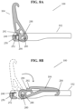
FIG. 7A is a cross-sectional side view of the step apparatus in a first position; andFIG. 7B is a cross-sectional side view of the step apparatus ofFIG. 7A being rotated from the first position to a second position. -
FIG. 8A is a cross-sectional side view of the step apparatus in the first position; andFIG. 8B is a cross-sectional side view of the step apparatus ofFIG. 8A being rotated from the first position to a folded position. -
FIG. 9A is a bottom view of the step apparatus in the first position; andFIG. 9B is a corresponding top view of the step apparatus ofFIG. 9A in the first position. -
FIG. 10A is a bottom view of the step apparatus in the second position; andFIG. 10B is a corresponding top view of the step apparatus ofFIG. 10A in the second position. -
FIG. 11A is a bottom view of the step apparatus in the folded position; andFIG. 11B is a corresponding top view of the step apparatus ofFIG. 11A in the folded position. -
FIG. 12 is a side view of the step apparatus in the first position removably coupled to a door latch element within a door well of a vehicle. -
FIG. 13 is a side view of the step apparatus in the second position removably coupled to a door latch element within a door well of a vehicle. -
FIG. 14 is a side view of the step apparatus in the folded position. -
FIG. 15 is a rear view of the axle structure and elongated support element within the step apparatus. - Corresponding reference characters indicate corresponding elements among the view of the drawings. The headings used in the figures do not limit the scope of the claims.
- The present disclosure generally relates to a step apparatus that removably couples to a door latch element of a door well of a vehicle. The step apparatus can include a load-supporting step structure, an elongated support element, and an axle structure rotatably coupling the load-supporting step structure to the elongated support element. The elongated support element can include a hook-shaped element configured to removably couple to the door latch element of the door well of a vehicle. The load-supporting step structure is configured to support the weight of a person when standing on the load-supporting step structure while the step apparatus is removably coupled to the door latch element. The step apparatus is further configured to include two or more positions of the elongated support element in relation to the load-supporting step structure, allowing the step apparatus to be removably coupled to both horizontal and angled door latch elements of vehicle door wells when the vehicle door is open, as well as be folded for easy storage.
- The step apparatus can thus be used to easily access the roof of the vehicle to which it is coupled. The removability of the step apparatus from the door well of the vehicle allows for use of the step apparatus without alteration to the vehicle. The two or more positions of the step apparatus allows for use of the step apparatus with various styles of vehicle door wells, as well as easy storage when not in use. As such, the present disclosure provides a unique and novel manner to provide a step to access the roof of a vehicle without alteration to the vehicle itself.
- Referring to
FIG. 1 , an embodiment of thestep apparatus 100 is shown. Thestep apparatus 100 includes a load-supportingstep structure 102 engaged to anelongated support element 104 through anaxle structure 106. Thestep apparatus 100 defines adistal end 116 and aproximal end 118. Theelongated support element 104 is rotatably coupled to the load-supportingstep structure 102 by theaxle structure 106 at or near theproximal end 118 of thestep structure 100. Theelongated support element 104 is operable to rotate about theaxle structure 106. Thus, thestep apparatus 100 is capable of rotating between two or more positions as described herein. - An exploded view of the
step apparatus 100 is depicted inFIG. 2 . As shown, thestep apparatus 100 may include astep portion 210, astep structure plate 230, and abackend housing 250, which when engaged together form the load-supportingstep structure 102. Thestep portion 210 provides a surface for a person to step, while thestep structure plate 230 provides additional support for the load-supportingstep structure 102 such that the load-supportingstep structure 102 can support a person's weight while stepping on thestep portion 210 of the load-supportingstep structure 102. Thebackend housing 250 holds thestep structure plate 230 and provides a surface at theproximal end 118 of thestep apparatus 100 that abuts the door well of a vehicle when thestep apparatus 100 is coupled to a door latch element. - The
step portion 210 of the load-supportingstep structure 102 defines atop portion 212, anopposite bottom portion 214, adistal end 216, and an oppositeproximal end 218. Thedistal end 216 andproximal end 218 of thestep portion 210 are located at or near thedistal end 116 andproximal end 118 of the load-supportingstep structure 102 respectively, when thestep portion 210 is coupled to thestep structure plate 230. Thestep portion 210 further defines arecess 220, anelongated slot 222, and anaxle bore 224. As shown, thestep portion 210 may further include a plurality ofprotrusions 226 along thetop portion 212 of thestep portion 210. In one aspect, theprotrusions 226 provide a textured surface on which a person can step to reduce the risk of slipping while placing the person's body weight on the load-supportingstep structure 102. - The
step structure plate 230 of the load-supportingstep structure 102 defines atop portion 232, anopposite bottom portion 234, adistal end 236, and an oppositeproximal end 238. Thedistal end 236 andproximal end 238 of thestep support structure 230 are also located at or near thedistal end 116 andproximal end 118 of the load-supportingstep structure 102, respectively. Thestep structure plate 230 further defines arecess 240, anelongated slot 242, and anaxle bore 244. Thestep structure plate 230 further may form aflange 246 configured to extend out and downward from theproximal end 238 of thestep structure plate 230. - In some embodiments, the
backend housing 250 includes aflange slot 252. Theflange 246 of thestep structure plate 230 is configured to be inserted into theflange slot 252 when thestep portion 210,step structure plate 230, andbackend housing 250 are coupled together to form the load-supportingstep structure 102. - When coupled together, the
top portion 232 of thestep support plate 230 contacts thebottom portion 214 of thestep portion 210. When theflange 246 is inserted into theflange slot 252 of thebackend housing 250 and thestep portion 210 is placed on top of thestep support plate 230, theproximal end 238 of thestep support plate 230 sits flush with thebackend housing 250 and theproximal end 218 of thestep portion 210 sits on top and is flush with thebackend housing 250. In addition, when coupled together, therecess 240,elongated slot 242, and axle bore 244 of thestep support structure 230 will align with therecess 220,elongated slot 222, and axle bore 224 of thestep portion 210, respectively. Thus, when coupled together, thestep portion 210,step support plate 230, andbackend housing 250 form the load-supportingstep structure 102 having adistal end 116 and aproximal end 118, while the axle bore 224/244 is configured to accept insertion of theaxle structure 106 and theelongated slot 222/242 is configured to accept insertion theelongated support structure 104. -
FIG. 2 further depicts the structure of theelongated support element 104. Theelongated support element 104 forms afirst end 280, asecond end 282, and anaxle aperture 288. In particular, thefirst end 280 is proximate to the load-supportingstep structure 102 such that thefirst end 280 is located at or near theproximal end 218 of the load-supportingstep structure 102. As shown, thesecond end 282 is distal from the load-supportingstep structure 102, while theaxle aperture 288 is positioned at thefirst end 280 of theelongated support element 104. Theelongated support element 104 may include additional apertures positioned between thefirst end 280 and thesecond end 282 or may only include theaxle aperture 288. - A hook-shaped
element 284 is defined at thesecond end 282 of theelongated support element 104. The hook-shapedelement 284 is configured to be removably coupled to a door latch element of a door well as shall be discussed in greater detail below. In some embodiments, theelongated support element 104 may further include acover 286. Thecover 286 is preferably the same shape as the hook-shapedelement 284 and configured to cover thesecond end 282 of theelongated support element 104. In other embodiments, the cover may not be used, or alternatively may cover more than thesecond end 282 of theelongated support element 104. - The
elongated support element 104 also defines afirst abutment portion 290 and asecond abutment portion 292. Thefirst abutment portion 290 and thesecond abutment portion 292 protrude from theelongated support element 104 and each forms a flat surface having a unique angle that abuts thestep structure plate 230. -
FIG. 2 further depicts the components of theaxle structure 106 that couples the load-supportingstep structure 102 to theelongated support element 104. Theaxle structure 106 is configured such that theelongated support element 104 may be removably coupled to the load supportingstep structure 102. Theaxle structure 106 may also be configured such that theelongated support element 104 is permanently coupled to the load supportingstep structure 102. Theaxle structure 106 includes anaxle 260 having anaxle head 262, afirst axle housing 264, asecond axle housing 266, andaxle nut 268, and aspring 270. Theaxle 260 is configured to pass through the axle bore 224 of thestep portion 210, the axle bore 244 of thestep structure plate 230, and theaxle aperture 288 of theelongated support element 104, thereby spanning from one side of the load-supportingstep structure 102 to the other. Thus, theaxle structure 106 rotatably couples theelongated support element 104 to the load-supportingstep structure 102. -
FIGS. 3-6 depict thestep apparatus 100 in a first position. Preferably, in the first position, theelongated support element 104 is at or substantially at a perpendicular angle in relation to the load-supportingstep structure 102. In other embodiments, the angle of the first position may differ. - In these embodiments, the
elongated support element 104 includes acover 286 that encloses thesecond end 282 of theelongated support element 104, and thus also the hook-shapedelement 284. As shown, thecover 286 preferably matches the shape of the hook-shapedelement 284, and is preferably made of a soft, non-metal material. In some embodiments, thecover 286 only covers the hook-shapedelement 284, while in other embodiments, thecover 286 extends further down theelongated support element 104 towards thesecond abutment portion 292. Thecover 286 provides a soft contact point for the hook-shapedelement 284 when removably coupled to a door latch element of a vehicle door well. - When viewing the
step apparatus 100 from its sides as shown inFIGS. 3-4 , theaxle structure 106 spans from one side of the load-supportingstep structure 102 to the opposite side. As shown inFIG. 3 , theaxle head 262 is accessible from one side such that theaxle structure 106 can be tightened, loosened, or removed from the load-supportingstep structure 102. In one embodiment, theaxle head 262 includes a hexagonal-recess for purposes of tightening theaxle 260, but other embodiments may use other head shapes without departing from the concepts disclosed herein. As shown inFIG. 4 , the opposite end of theaxle 260 is visible through the axle bore 224 of thestep portion 210, and preferably sits flush with the side of thestep portion 210. As discussed, removing theaxle structure 106 from thestep apparatus 100 will decouple theelongated support element 104 from the load-supportingstep structure 102. - When viewing the
step apparatus 100 from the front (as shown inFIG. 5 ), theelongated support element 104 is positioned central to the load-supportingstep structure 102 and is placed between thefirst axle housing 264 and thesecond axle housing 266. As shown, thefirst end 280 of theelongated support element 104 extends below the body of the load-supportingstep structure 102, and is thus visible when viewed from the front, back, or sides. - When viewing the
step apparatus 100 from the back (as shown inFIG. 6 ), thebackend housing 250 and theproximal end 218 of thestep portion 210 make up theproximal end 118 of the load-supportingstep structure 102. Visible above theproximal end 118 of the load-supportingstep structure 102 is thesecond abutment portion 292, which is not engaged while thestep apparatus 100 is in its first position. Additionally, while theprotrusions 226 are generally visible from the front of the step apparatus 100 (as shown inFIG. 5 ), theprotrusions 226 are generally not visible when viewed from the rear, as theproximal end 118 of the load-supportingstep structure 102 is at the same level or higher than theprotrusions 226. -
FIGS. 7A-7B and 8A-8B depict thestep apparatus 100 shifting from its first position (FIGS. 7A and8A ) to a second position (FIG. 7B ) and a folded position (FIG. 8B ). Referring toFIGS. 7A and8A , thestep apparatus 100 is depicted in its first position. As shown, theflange 246 of thestep structure plate 230 is inserted into theflange slot 252 of thebackend housing 250, thereby securing thestep structure plate 230 within the load-supportingstep structure 102. Thefirst abutment portion 290 of theelongated support element 104 abuts thetop portion 232 of thestep structure plate 230 proximate theflange 246, thereby providing support for the load-supportingstep structure 102. In an exemplary embodiment, thefirst abutment portion 290 is angled such that the position of theelongated support element 104 is at a substantially perpendicular angle with respect to the load-supportingstep structure 102. - As also shown in
FIGS. 7A and8A , theaxle 260 passes through theaxle aperture 288 of theelongated support element 104. In one embodiment, theaxle aperture 288 is bean-shaped such that theaxle aperture 288 has a first position and a second position with a hump formed between the first position and the second position. When thestep apparatus 100 is in its first position, theaxle 260 passes through theaxle aperture 288 in its first position and is secured by the force of thefirst abutment portion 290 abutting thestep structure plate 230 and theaxle 260 abutting the edge of theaxle aperture 288 in its first position when a person steps on the load-supportingstep structure 102. -
FIG. 7B depicts thestep apparatus 100 shifting from the first position to the second position. In an embodiment, when thestep apparatus 100 shifts from the first position to the second position, the load-supportingstep structure 102, including thebackend housing 250 and stepstructure plate 230, remain stationary. To shift thestep apparatus 100 from the first position to the second position, theelongated support element 104 is first pushed towards thedistal end 116 of the load-supportingstep structure 102 without rotating the elongated support element 114. Pushing theelongated support element 104 towards thedistal end 116 of the load-supportingstep structure 102 enablesaxle 260 to shift from the first position of theaxle aperture 288 to the second position of theaxle aperture 288. Once theaxle 260 is shifted to the second position of theaxle aperture 288, the hook-shapedportion 284 of theelongated support element 104 is able to be rotated towards theproximal end 118 of the load-supportingstructure 102 until thesecond abutment portion 292 of theelongated support element 104 abuts thetop portion 232 of thestep support plate 230. This configuration allows theelongated support element 104 to rotate about theaxle 260, thereby shifting theelongated support element 104 into the second position of theaxle aperture 288 in relation to theaxle 260. Once theelongated support element 104 is shifted from the first position of theaxle aperture 288 to the second position of theaxle aperture 288, thesecond abutment portion 292 of theelongated support element 104 abuts thetop portion 232 of thestep support plate 230, thereby securing thestep apparatus 100 in its second position. - In one embodiment, the
second abutment portion 292 is angled such that the position of theelongated support element 104 is at a substantially obtuse angle with respect to the load-supportingstep structure 102. In other embodiments, the angle of the first position may differ. Similar to when thestep apparatus 100 is in its first position, when thestep apparatus 100 is in its second position, thestep apparatus 100 is secured in the second position by the force of thesecond abutment portion 292 abutting thestep structure plate 230 and theaxle 260 abutting the edge of theaxle aperture 288 in its second position when a person steps on the load-supportingstep structure 102. Pulling theelongated support element 104 back towards the first position will return thestep apparatus 100 to its first position depicted inFIGS. 7A and8A through the same mechanism but reversed. -
FIG. 8B depicts thestep apparatus 100 shifting from the first position to the folded position. In one embodiment, when thestep apparatus 100 shifts from the first position to the folded position, the load-supportingstep structure 102, including thebackend housing 250 and stepstructure plate 230, remain stationary. To shift thestep apparatus 100 from the first position to the folded position, thesecond end 282 of theelongated support element 104 is pushed towards thedistal end 116 of the load-supportingstep structure 102.. Once theelongated support element 104 is shifted from the first position to the folded position, neither thefirst abutment portion 290 nor thesecond abutment portion 292 of theelongated support element 104 abut thetop portion 232 of thestep support plate 230. Instead, theelongated support element 104 is folded down into theelongated slot 222 of thestep portion 210 and theelongated slot 242 of thestep structure plate 230. Therecess 220 of thestep portion 210 and therecess 240 of thestep structure plate 230 are configured to receive thesecond end 282 and the hook-shapedportion 284 of theelongated support element 104 such that theelongated support element 104 is substantially housed within the load-supportingstep structure 102. -
FIGS. 9A and 9B depict the respective top view and bottom view of thestep apparatus 100 in its first position, whileFIGS. 10A and 10B depict the respective top view and bottom view of thestep apparatus 100 in its second position. Finally,FIGS. 11A and 11B depict the respective top view and bottom view of thestep apparatus 100 in its folded position. As shown and previously described, when thestep portion 210,step structure plate 230, andbackend housing 250 are coupled to form theelongated slot 222 of thestep portion 210 and theelongated slot 242 of thestep structure plate 230 align such that a single elongated slot is present in the load-supportingstep structure 102. Additionally, therecess 220 of thestep portion 210 and therecess 240 of thestep structure plate 230 similarly align to form a single recess for the load-supportingstep structure 102. As shown in the embodiment ofFIGS. 9A ,10A , and11A ,step support plate 230 is configured to sit inside the body of thestep portion 210 and is preferably the same or smaller in size in comparison to thestep portion 210. When viewed from the bottom, thebottom portion 234 of thestep structure plate 230 is visible, and thetop portion 232 of thestep structure plate 230 abuts thebottom portion 214 of thestep portion 210. - As further shown in
FIGS. 9B ,10B , and11B , thetop portion 212 of thestep portion 210 forms a plurality ofprotrusions 226. In one embodiment, the plurality ofprotrusions 226 provide a textured surface for a person to step upon, thereby minimizing the chance of slipping off the load-bearing step structure 102. In one embodiment depicted byFIG. 9B , theprotrusions 226 are truncated pyramids protruding out from thetop surface 212 of thestep portion 210. It is appreciated that other shapes and sizes of theprotrusions 226 may be used without departing from the scope of the disclosure. Generally, theprotrusions 226 may be formed at the same time as thestep portion 210 as a unitary component, or alternatively may be added to thetop portion 212 of thestep portion 210 after forming thestep portion 210. - As further shown in
FIGS. 11A and 11B , when thestep apparatus 100 in its folded position, the alignedelongated slots 222/242 of the load-supportingstep structure 102 receive theelongated support element 104 such that theelongated support element 104 is positioned substantially within the body of the load-supportingstep structure 102. Additionally, the alignedrecesses 220/240 of the load-supportingstep structure 102 receive the hook-shapedelement 284 of theelongated support element 104 such that the hook-shapedelement 284 is also positioned substantially within the body of the load-supportingstep structure 102. Thus, when thestep apparatus 100 is in its folded position, it can be easily stored within a vehicle. -
FIGS. 12-14 depict thestep structure 100 in each respective position placed on adoor latch element 10 of a vehicle. As shown, thedoor latch element 10 generally includes adoor frame 12, abase plate 14, and aU-shaped latch element 16. These descriptions are for illustrative purposes, and it is appreciated that thestep apparatus 100 is intended to work with many types of vehicle door wells having aU-shaped latch element 16 for thestep apparatus 100 to removably couple. - As shown in
FIGS. 12 and 13 , thestep apparatus 100 is removably coupled to thedoor latch element 10 of a vehicle. Thesecond end 282 of theelongated support element 104 having the hook-shapedelement 284 is positioned through theU-shaped latch element 16 and hooked ontoU-shaped latch element 16. Once the hook-shapedelement 284 is hooked onto theU-shaped latch element 16, thebackend housing 250, and thus theproximal end 118 of the load-supportingstep structure 102, abuts thedoor frame 12 of the vehicle. Thus, when a person steps on the load-supportingstep structure 102 when thestep apparatus 100 is removably coupled to thedoor latch element 10, theproximal end 118 of the load-supportingstep structure 102 abuts thedoor frame 12 while the hook-shapedelement 284 of theelongated support element 104 becomes engaged to the outer portion of theU-shaped latch element 16. Thus, in one embodiment, theelongated support element 104 does not contact thedoor frame 12. - As shown in
FIG. 12 , the load-supportingstep structure 102 of thestep apparatus 100 in its first position provides a horizontal surface for a person to step on to access the roof of a vehicle. This first position provides the horizontal surface where thedoor latch element 10 is vertical in relation to the ground surface. As shown inFIG. 13 , the load-supportingstep structure 102 of thestep apparatus 100 in its second position also provides a horizontal surface for a person to step to access the roof of a vehicle. This second position provides the horizontal surface where thedoor latch element 10 is in an angled position in relation to the ground surface. When thestep apparatus 100 is in is folded position, as shown inFIG. 14 , thestep apparatus 100 folds to a substantially flat position for storage in the vehicle. -
FIG. 15 depicts the internal structure of theaxle structure 106 when thestep apparatus 100 is in any position. As previously shown and discussed, theaxle structure 106 includes theaxle 260 having theaxle head 262,first axle housing 264,second axle housing 266, andaxle nut 268. Theaxle 260 is first positioned through first the axle bore 224 of thestep portion 210, then through the axle bore 244 of thestep structure plate 230, thefirst axle housing 264, theaxle aperture 288 of theelongated support element 104, thesecond axle housing 266, the opposing axle bore 244 of thestep structure plate 230, and then finally the opposing axle bore 224 of thestep portion 210. Contained within thefirst axle housing 264 is theaxle nut 268. Thefirst axle housing 264 is configured such that theaxle nut 268 is unable to rotate within thefirst axle housing 264, thereby allowing theaxle 260 to be tightened when removably coupling theelongated support element 104 to the load-supportingstep structure 102. Once tightened, theelongated support element 104 is able to rotate about theaxle 260, thereby enabling theelongated support element 104 to freely shift between the first position, second position, and folded position. - In some embodiments, the
axle structure 106 may also include aspring 270. In these embodiments, thespring 270 is housed within thesecond axle housing 266 on the opposite side of theelongated support element 104 from thefirst axle housing 264. Thespring 270 acts to provide additional tension on theelongated support element 104 when theaxle structure 106 is secured, thus providing feedback to a person using thestep apparatus 100. Additionally, thespring 270 provides additional tension when shifting thestep apparatus 100 between the first position, second position, and folded position. - It should be understood from the foregoing that, while particular embodiments have been illustrated and described, various modifications can be made thereto without departing from the spirit and scope of the invention as will be apparent to those skilled in the art. Such changes and modifications are within the scope and teachings of this invention as defined in the claims appended hereto.
-
- 1. A step apparatus, comprising:
- a step structure defining an axle bore;
- an elongated support element coupled to the step structure, the elongated support element having a hook-shaped element and an axle aperture; and
- an axle coupling the elongated support element to the step structure through the axle bore and axle aperture;
- wherein the elongated support element is operable for rotating position about the axle, and the hook-shaped element is configured to be removably coupled to a latch element of a vehicle door well.
- 2. The step apparatus of
clause 1, wherein the elongated support element is operable to rotate between a first position and a folded position. - 3. The step apparatus of clause 2, wherein the elongated support element in the first position is at a substantially perpendicular angle in relation to the step structure.
- 4. The step apparatus of
clause 1, wherein the elongated support element is removably coupled to the step structure. - 5. The step apparatus of
clause 1, wherein the axle aperture includes a first position and a second position through which the axle rotates. - 6. The step apparatus of
clause 1, wherein the axle is housed by the axle bore, the axle aperture, and one or more axle housings. - 7. The step apparatus of clause 6, wherein the one or more axle housings include a spring.
- 8. A step apparatus, comprising:
- a step structure having a proximal end and a distal end;
- an elongated support element having a first end and a second end, the first end of the elongated support element being positioned proximate to the proximal end of the step structure and the second end of the elongated support element defining a hook-shaped element; and
- an axle structure removably coupling the first end of the elongated support element to the proximal end of the step structure, the axle structure configured to allow the elongated support element to shift between a first position, a second position, and a folded position.
- 9. The step apparatus of clause 8, wherein the elongated support element in the first position is at a substantially perpendicular angle in relation to the step structure, and the elongated support element in the second position is at a substantially obtuse angle in relation to the step structure.
- 10. The step apparatus of clause 8, wherein the step structure further includes an elongated slot and a recess.
- 11. The step apparatus of
clause 10, wherein when the elongated support element rotates to the folded position, the recess receives the hook-shaped element. - 12. The step apparatus of clause 8, wherein the hook-shaped element is configured to removably couple to a latch element of a door well of a vehicle.
- 13. The step apparatus of
clause 12, wherein the elongated support element does not contact the door well of the vehicle when the hook-shaped element is removably coupled to the latch element. - 14. The step apparatus of
clause 12, wherein the proximal end of the step structure abuts the door well of the vehicle when the hook-shaped element is removably coupled to the latch element. - 15. The step apparatus of clause 8, wherein the step structure defines a plurality of protrusions.
- 16. A method of using a step apparatus, comprising:
- providing a step structure and an elongated support element coupled to the step structure by an axle structure, the step structure having a proximal end and a distal end, the elongated support element having a hook-shaped element, and an axle coupling the elongated support element to the step structure for rotating the step structure relative to the elongated support element to at least one other position; and
- coupling the hook-shaped element to a latch element of a door well of a vehicle.
- 17. The method of
clause 16, further comprising:
decoupling the hook-shaped element of the elongated support element from the latch element of the door well of the vehicle. - 18. The method of clause 17, further comprising:
folding the elongated support element into the step structure. - 19. The method of
clause 16, wherein when coupling the hook-shaped element to the latch element, the proximal end of the step structure abuts the door well of the vehicle. - 20. The method of
clause 16, wherein when coupling the hook-shaped element to the latch element, the proximal end of the step structure abuts the door well of the vehicle and the elongated support element does not contact the door well of the vehicle.
Claims (15)
- A step apparatus, comprising:a step structure defining an axle bore;an elongated support element coupled to the step structure, the elongated support element having a hook-shaped element and an axle aperture; andan axle coupling the elongated support element to the step structure through the axle bore and axle aperture;wherein the elongated support element is operable for rotating position about the axle, and the hook-shaped element is configured to be removably coupled to a latch element of a vehicle door well.
- The step apparatus of claim 1, wherein the elongated support element is operable to rotate between a first position and a folded position, optionally wherein the elongated support element in the first position is at a substantially perpendicular angle in relation to the step structure.
- The step apparatus of claim 1, wherein the elongated support element is removably coupled to the step structure, or wherein the axle aperture includes a first position and a second position through which the axle rotates.
- The step apparatus of claim 1, wherein the axle is housed by the axle bore, the axle aperture, and one or more axle housings, optionally wherein the one or more axle housings include a spring.
- A step apparatus, comprising:a step structure having a proximal end and a distal end;an elongated support element having a first end and a second end, the first end of the elongated support element being positioned proximate to the proximal end of the step structure and the second end of the elongated support element defining a hook-shaped element; andan axle structure removably coupling the first end of the elongated support element to the proximal end of the step structure, the axle structure configured to allow the elongated support element to shift between a first position, a second position, and a folded position.
- The step apparatus of claim 5, wherein the elongated support element in the first position is at a substantially perpendicular angle in relation to the step structure, and the elongated support element in the second position is at a substantially obtuse angle in relation to the step structure.
- The step apparatus of claim 5, wherein the step structure further includes an elongated slot and a recess, optionally wherein when the elongated support element rotates to the folded position, the recess receives the hook-shaped element.
- The step apparatus of claim 5, wherein the hook-shaped element is configured to removably couple to a latch element of a door well of a vehicle.
- The step apparatus of claim 8, wherein the elongated support element does not contact the door well of the vehicle when the hook-shaped element is removably coupled to the latch element, or wherein the proximal end of the step structure abuts the door well of the vehicle when the hook-shaped element is removably coupled to the latch element.
- The step apparatus of claim 5, wherein the step structure defines a plurality of protrusions.
- A method of using a step apparatus, comprising:providing a step structure and an elongated support element coupled to the step structure by an axle structure, the step structure having a proximal end and a distal end, the elongated support element having a hook-shaped element, and an axle coupling the elongated support element to the step structure for rotating the step structure relative to the elongated support element to at least one other position; andcoupling the hook-shaped element to a latch element of a door well of a vehicle.
- The method of claim 11, further comprising:
decoupling the hook-shaped element of the elongated support element from the latch element of the door well of the vehicle. - The method of claim 12, further comprising:
folding the elongated support element into the step structure. - The method of claim 11, wherein when coupling the hook-shaped element to the latch element, the proximal end of the step structure abuts the door well of the vehicle.
- The method of claim 11, wherein when coupling the hook-shaped element to the latch element, the proximal end of the step structure abuts the door well of the vehicle and the elongated support element does not contact the door well of the vehicle.
Applications Claiming Priority (1)
| Application Number | Priority Date | Filing Date | Title |
|---|---|---|---|
| US18/318,633 US20230339405A1 (en) | 2017-01-09 | 2023-05-16 | Vehicle door well step apparatus |
Publications (1)
| Publication Number | Publication Date |
|---|---|
| EP4464558A1 true EP4464558A1 (en) | 2024-11-20 |
Family
ID=91129964
Family Applications (1)
| Application Number | Title | Priority Date | Filing Date |
|---|---|---|---|
| EP24176453.9A Withdrawn EP4464558A1 (en) | 2023-05-16 | 2024-05-16 | Vehicle door well step apparatus |
Country Status (1)
| Country | Link |
|---|---|
| EP (1) | EP4464558A1 (en) |
Citations (7)
| Publication number | Priority date | Publication date | Assignee | Title |
|---|---|---|---|---|
| CN208149179U (en) * | 2018-05-04 | 2018-11-27 | 周容 | a car pedal |
| CN208646734U (en) * | 2018-07-31 | 2019-03-26 | 李艳芬 | A kind of auto pedal |
| CN208698641U (en) * | 2018-09-21 | 2019-04-05 | 东莞市千鼎五金制品有限公司 | A booster pedal for car door lock |
| CA3024597A1 (en) * | 2018-04-28 | 2019-10-28 | Xufeng MAO | Footrest for assisting in touching car roof |
| CN110641373A (en) * | 2019-10-08 | 2020-01-03 | 泉州市双塔汽车零件有限公司 | Pedal assembly and using method |
| US20200238915A1 (en) * | 2019-01-25 | 2020-07-30 | Toyota Motor Engineering & Manufacturing North America, Inc. | Roof access device for a vehicle |
| CN114919500A (en) * | 2022-05-19 | 2022-08-19 | 宁波纽特汽车配件有限公司 | Angle-adjustable doorframe pedal |
-
2024
- 2024-05-16 EP EP24176453.9A patent/EP4464558A1/en not_active Withdrawn
Patent Citations (7)
| Publication number | Priority date | Publication date | Assignee | Title |
|---|---|---|---|---|
| CA3024597A1 (en) * | 2018-04-28 | 2019-10-28 | Xufeng MAO | Footrest for assisting in touching car roof |
| CN208149179U (en) * | 2018-05-04 | 2018-11-27 | 周容 | a car pedal |
| CN208646734U (en) * | 2018-07-31 | 2019-03-26 | 李艳芬 | A kind of auto pedal |
| CN208698641U (en) * | 2018-09-21 | 2019-04-05 | 东莞市千鼎五金制品有限公司 | A booster pedal for car door lock |
| US20200238915A1 (en) * | 2019-01-25 | 2020-07-30 | Toyota Motor Engineering & Manufacturing North America, Inc. | Roof access device for a vehicle |
| CN110641373A (en) * | 2019-10-08 | 2020-01-03 | 泉州市双塔汽车零件有限公司 | Pedal assembly and using method |
| CN114919500A (en) * | 2022-05-19 | 2022-08-19 | 宁波纽特汽车配件有限公司 | Angle-adjustable doorframe pedal |
Similar Documents
| Publication | Publication Date | Title |
|---|---|---|
| US6010187A (en) | Chair for a mechanic | |
| US5601268A (en) | Drink holder support structures interfitting within existing space | |
| US20020130227A1 (en) | Holder, in particular for an electronical device or an exhibition object | |
| US6092656A (en) | Wrench socket holder with locking member | |
| US6378710B1 (en) | Adjustable shelf unit | |
| US5984347A (en) | Accessory in the form of an attache case for motor vehicle | |
| US7681852B2 (en) | Vehicle cup and plate holders | |
| US4984722A (en) | Adjustable cup holder | |
| US10232793B2 (en) | Truck bed integrated fold-out table | |
| US7080417B2 (en) | Foldable chair for bathroom | |
| US20230339405A1 (en) | Vehicle door well step apparatus | |
| US20020104709A1 (en) | Tool box mountable on the top step of a foldable ladder | |
| US20030167074A1 (en) | Docking station for defibrillator | |
| US20050122016A1 (en) | System for mounting, accessing, moving and folding away articles under a downwardly facing surface | |
| EP4464558A1 (en) | Vehicle door well step apparatus | |
| US7703225B2 (en) | Frameless display fixture | |
| CN113525240B (en) | Vehicle door pedal | |
| US5749475A (en) | Tire support | |
| US20080083682A1 (en) | Display stand merchandise tray | |
| US6915916B2 (en) | Apparatus and method of constructing display | |
| AU2005294386A1 (en) | Room service table | |
| US20030111503A1 (en) | Automobile trunk compartmentalizer | |
| EP1486409A3 (en) | Housing support structure of an anti-theft u-shaped lockin tool in a vehicle | |
| CA2056807C (en) | Display device | |
| JP2003233323A (en) | Holder for display |
Legal Events
| Date | Code | Title | Description |
|---|---|---|---|
| PUAI | Public reference made under article 153(3) epc to a published international application that has entered the european phase |
Free format text: ORIGINAL CODE: 0009012 |
|
| STAA | Information on the status of an ep patent application or granted ep patent |
Free format text: STATUS: THE APPLICATION HAS BEEN PUBLISHED |
|
| AK | Designated contracting states |
Kind code of ref document: A1 Designated state(s): AL AT BE BG CH CY CZ DE DK EE ES FI FR GB GR HR HU IE IS IT LI LT LU LV MC ME MK MT NL NO PL PT RO RS SE SI SK SM TR |
|
| STAA | Information on the status of an ep patent application or granted ep patent |
Free format text: STATUS: REQUEST FOR EXAMINATION WAS MADE |
|
| STAA | Information on the status of an ep patent application or granted ep patent |
Free format text: STATUS: EXAMINATION IS IN PROGRESS |
|
| 17P | Request for examination filed |
Effective date: 20250508 |
|
| 17Q | First examination report despatched |
Effective date: 20250604 |
|
| STAA | Information on the status of an ep patent application or granted ep patent |
Free format text: STATUS: THE APPLICATION IS DEEMED TO BE WITHDRAWN |
|
| 18D | Application deemed to be withdrawn |
Effective date: 20251007 |