EP4464538A1 - Vehicle drive system - Google Patents
Vehicle drive system Download PDFInfo
- Publication number
- EP4464538A1 EP4464538A1 EP24174727.8A EP24174727A EP4464538A1 EP 4464538 A1 EP4464538 A1 EP 4464538A1 EP 24174727 A EP24174727 A EP 24174727A EP 4464538 A1 EP4464538 A1 EP 4464538A1
- Authority
- EP
- European Patent Office
- Prior art keywords
- motor
- drive system
- rotor
- vehicle
- vehicle drive
- Prior art date
- Legal status (The legal status is an assumption and is not a legal conclusion. Google has not performed a legal analysis and makes no representation as to the accuracy of the status listed.)
- Pending
Links
- 239000004020 conductor Substances 0.000 claims abstract description 44
- 230000001360 synchronised effect Effects 0.000 claims abstract description 35
- 230000010349 pulsation Effects 0.000 claims description 36
- 229910000859 α-Fe Inorganic materials 0.000 claims description 3
- 230000008859 change Effects 0.000 description 10
- 230000006870 function Effects 0.000 description 6
- 230000000694 effects Effects 0.000 description 4
- 238000004891 communication Methods 0.000 description 3
- 230000001172 regenerating effect Effects 0.000 description 3
- 239000011347 resin Substances 0.000 description 3
- 229920005989 resin Polymers 0.000 description 3
- XEEYBQQBJWHFJM-UHFFFAOYSA-N Iron Chemical compound [Fe] XEEYBQQBJWHFJM-UHFFFAOYSA-N 0.000 description 2
- 230000001133 acceleration Effects 0.000 description 2
- 230000004323 axial length Effects 0.000 description 2
- 230000008901 benefit Effects 0.000 description 2
- 238000001514 detection method Methods 0.000 description 2
- 238000010586 diagram Methods 0.000 description 2
- 239000012212 insulator Substances 0.000 description 2
- 239000000696 magnetic material Substances 0.000 description 2
- 238000000034 method Methods 0.000 description 2
- 230000009467 reduction Effects 0.000 description 2
- 239000003507 refrigerant Substances 0.000 description 2
- 230000004044 response Effects 0.000 description 2
- 238000004904 shortening Methods 0.000 description 2
- 238000003466 welding Methods 0.000 description 2
- 238000004804 winding Methods 0.000 description 2
- RYGMFSIKBFXOCR-UHFFFAOYSA-N Copper Chemical compound [Cu] RYGMFSIKBFXOCR-UHFFFAOYSA-N 0.000 description 1
- HBBGRARXTFLTSG-UHFFFAOYSA-N Lithium ion Chemical compound [Li+] HBBGRARXTFLTSG-UHFFFAOYSA-N 0.000 description 1
- 229910052779 Neodymium Inorganic materials 0.000 description 1
- 229910000831 Steel Inorganic materials 0.000 description 1
- 230000009286 beneficial effect Effects 0.000 description 1
- 230000005540 biological transmission Effects 0.000 description 1
- 238000002485 combustion reaction Methods 0.000 description 1
- 238000000748 compression moulding Methods 0.000 description 1
- 239000002826 coolant Substances 0.000 description 1
- 238000001816 cooling Methods 0.000 description 1
- 229910052802 copper Inorganic materials 0.000 description 1
- 239000010949 copper Substances 0.000 description 1
- 230000008878 coupling Effects 0.000 description 1
- 238000010168 coupling process Methods 0.000 description 1
- 238000005859 coupling reaction Methods 0.000 description 1
- 230000005347 demagnetization Effects 0.000 description 1
- 230000005674 electromagnetic induction Effects 0.000 description 1
- 230000001771 impaired effect Effects 0.000 description 1
- 238000001746 injection moulding Methods 0.000 description 1
- 229910052742 iron Inorganic materials 0.000 description 1
- 229910001416 lithium ion Inorganic materials 0.000 description 1
- 239000006247 magnetic powder Substances 0.000 description 1
- 229910052987 metal hydride Inorganic materials 0.000 description 1
- 238000012986 modification Methods 0.000 description 1
- 230000004048 modification Effects 0.000 description 1
- 230000007659 motor function Effects 0.000 description 1
- QEFYFXOXNSNQGX-UHFFFAOYSA-N neodymium atom Chemical compound [Nd] QEFYFXOXNSNQGX-UHFFFAOYSA-N 0.000 description 1
- 239000000843 powder Substances 0.000 description 1
- 229910052761 rare earth metal Inorganic materials 0.000 description 1
- 150000002910 rare earth metals Chemical class 0.000 description 1
- 239000010959 steel Substances 0.000 description 1
Images






Classifications
-
- B—PERFORMING OPERATIONS; TRANSPORTING
- B60—VEHICLES IN GENERAL
- B60L—PROPULSION OF ELECTRICALLY-PROPELLED VEHICLES; SUPPLYING ELECTRIC POWER FOR AUXILIARY EQUIPMENT OF ELECTRICALLY-PROPELLED VEHICLES; ELECTRODYNAMIC BRAKE SYSTEMS FOR VEHICLES IN GENERAL; MAGNETIC SUSPENSION OR LEVITATION FOR VEHICLES; MONITORING OPERATING VARIABLES OF ELECTRICALLY-PROPELLED VEHICLES; ELECTRIC SAFETY DEVICES FOR ELECTRICALLY-PROPELLED VEHICLES
- B60L50/00—Electric propulsion with power supplied within the vehicle
- B60L50/50—Electric propulsion with power supplied within the vehicle using propulsion power supplied by batteries or fuel cells
- B60L50/51—Electric propulsion with power supplied within the vehicle using propulsion power supplied by batteries or fuel cells characterised by AC-motors
-
- H—ELECTRICITY
- H02—GENERATION; CONVERSION OR DISTRIBUTION OF ELECTRIC POWER
- H02K—DYNAMO-ELECTRIC MACHINES
- H02K21/00—Synchronous motors having permanent magnets; Synchronous generators having permanent magnets
- H02K21/46—Motors having additional short-circuited winding for starting as an asynchronous motor
-
- B—PERFORMING OPERATIONS; TRANSPORTING
- B60—VEHICLES IN GENERAL
- B60L—PROPULSION OF ELECTRICALLY-PROPELLED VEHICLES; SUPPLYING ELECTRIC POWER FOR AUXILIARY EQUIPMENT OF ELECTRICALLY-PROPELLED VEHICLES; ELECTRODYNAMIC BRAKE SYSTEMS FOR VEHICLES IN GENERAL; MAGNETIC SUSPENSION OR LEVITATION FOR VEHICLES; MONITORING OPERATING VARIABLES OF ELECTRICALLY-PROPELLED VEHICLES; ELECTRIC SAFETY DEVICES FOR ELECTRICALLY-PROPELLED VEHICLES
- B60L15/00—Methods, circuits, or devices for controlling the traction-motor speed of electrically-propelled vehicles
- B60L15/20—Methods, circuits, or devices for controlling the traction-motor speed of electrically-propelled vehicles for control of the vehicle or its driving motor to achieve a desired performance, e.g. speed, torque, programmed variation of speed
-
- B—PERFORMING OPERATIONS; TRANSPORTING
- B60—VEHICLES IN GENERAL
- B60L—PROPULSION OF ELECTRICALLY-PROPELLED VEHICLES; SUPPLYING ELECTRIC POWER FOR AUXILIARY EQUIPMENT OF ELECTRICALLY-PROPELLED VEHICLES; ELECTRODYNAMIC BRAKE SYSTEMS FOR VEHICLES IN GENERAL; MAGNETIC SUSPENSION OR LEVITATION FOR VEHICLES; MONITORING OPERATING VARIABLES OF ELECTRICALLY-PROPELLED VEHICLES; ELECTRIC SAFETY DEVICES FOR ELECTRICALLY-PROPELLED VEHICLES
- B60L15/00—Methods, circuits, or devices for controlling the traction-motor speed of electrically-propelled vehicles
- B60L15/20—Methods, circuits, or devices for controlling the traction-motor speed of electrically-propelled vehicles for control of the vehicle or its driving motor to achieve a desired performance, e.g. speed, torque, programmed variation of speed
- B60L15/2045—Methods, circuits, or devices for controlling the traction-motor speed of electrically-propelled vehicles for control of the vehicle or its driving motor to achieve a desired performance, e.g. speed, torque, programmed variation of speed for optimising the use of energy
-
- B—PERFORMING OPERATIONS; TRANSPORTING
- B60—VEHICLES IN GENERAL
- B60L—PROPULSION OF ELECTRICALLY-PROPELLED VEHICLES; SUPPLYING ELECTRIC POWER FOR AUXILIARY EQUIPMENT OF ELECTRICALLY-PROPELLED VEHICLES; ELECTRODYNAMIC BRAKE SYSTEMS FOR VEHICLES IN GENERAL; MAGNETIC SUSPENSION OR LEVITATION FOR VEHICLES; MONITORING OPERATING VARIABLES OF ELECTRICALLY-PROPELLED VEHICLES; ELECTRIC SAFETY DEVICES FOR ELECTRICALLY-PROPELLED VEHICLES
- B60L58/00—Methods or circuit arrangements for monitoring or controlling batteries or fuel cells, specially adapted for electric vehicles
- B60L58/10—Methods or circuit arrangements for monitoring or controlling batteries or fuel cells, specially adapted for electric vehicles for monitoring or controlling batteries
-
- B—PERFORMING OPERATIONS; TRANSPORTING
- B60—VEHICLES IN GENERAL
- B60L—PROPULSION OF ELECTRICALLY-PROPELLED VEHICLES; SUPPLYING ELECTRIC POWER FOR AUXILIARY EQUIPMENT OF ELECTRICALLY-PROPELLED VEHICLES; ELECTRODYNAMIC BRAKE SYSTEMS FOR VEHICLES IN GENERAL; MAGNETIC SUSPENSION OR LEVITATION FOR VEHICLES; MONITORING OPERATING VARIABLES OF ELECTRICALLY-PROPELLED VEHICLES; ELECTRIC SAFETY DEVICES FOR ELECTRICALLY-PROPELLED VEHICLES
- B60L2220/00—Electrical machine types; Structures or applications thereof
- B60L2220/10—Electrical machine types
- B60L2220/12—Induction machines
-
- B—PERFORMING OPERATIONS; TRANSPORTING
- B60—VEHICLES IN GENERAL
- B60L—PROPULSION OF ELECTRICALLY-PROPELLED VEHICLES; SUPPLYING ELECTRIC POWER FOR AUXILIARY EQUIPMENT OF ELECTRICALLY-PROPELLED VEHICLES; ELECTRODYNAMIC BRAKE SYSTEMS FOR VEHICLES IN GENERAL; MAGNETIC SUSPENSION OR LEVITATION FOR VEHICLES; MONITORING OPERATING VARIABLES OF ELECTRICALLY-PROPELLED VEHICLES; ELECTRIC SAFETY DEVICES FOR ELECTRICALLY-PROPELLED VEHICLES
- B60L2220/00—Electrical machine types; Structures or applications thereof
- B60L2220/10—Electrical machine types
- B60L2220/14—Synchronous machines
-
- B—PERFORMING OPERATIONS; TRANSPORTING
- B60—VEHICLES IN GENERAL
- B60L—PROPULSION OF ELECTRICALLY-PROPELLED VEHICLES; SUPPLYING ELECTRIC POWER FOR AUXILIARY EQUIPMENT OF ELECTRICALLY-PROPELLED VEHICLES; ELECTRODYNAMIC BRAKE SYSTEMS FOR VEHICLES IN GENERAL; MAGNETIC SUSPENSION OR LEVITATION FOR VEHICLES; MONITORING OPERATING VARIABLES OF ELECTRICALLY-PROPELLED VEHICLES; ELECTRIC SAFETY DEVICES FOR ELECTRICALLY-PROPELLED VEHICLES
- B60L2240/00—Control parameters of input or output; Target parameters
- B60L2240/40—Drive Train control parameters
- B60L2240/42—Drive Train control parameters related to electric machines
-
- B—PERFORMING OPERATIONS; TRANSPORTING
- B60—VEHICLES IN GENERAL
- B60L—PROPULSION OF ELECTRICALLY-PROPELLED VEHICLES; SUPPLYING ELECTRIC POWER FOR AUXILIARY EQUIPMENT OF ELECTRICALLY-PROPELLED VEHICLES; ELECTRODYNAMIC BRAKE SYSTEMS FOR VEHICLES IN GENERAL; MAGNETIC SUSPENSION OR LEVITATION FOR VEHICLES; MONITORING OPERATING VARIABLES OF ELECTRICALLY-PROPELLED VEHICLES; ELECTRIC SAFETY DEVICES FOR ELECTRICALLY-PROPELLED VEHICLES
- B60L2240/00—Control parameters of input or output; Target parameters
- B60L2240/40—Drive Train control parameters
- B60L2240/42—Drive Train control parameters related to electric machines
- B60L2240/423—Torque
-
- B—PERFORMING OPERATIONS; TRANSPORTING
- B60—VEHICLES IN GENERAL
- B60L—PROPULSION OF ELECTRICALLY-PROPELLED VEHICLES; SUPPLYING ELECTRIC POWER FOR AUXILIARY EQUIPMENT OF ELECTRICALLY-PROPELLED VEHICLES; ELECTRODYNAMIC BRAKE SYSTEMS FOR VEHICLES IN GENERAL; MAGNETIC SUSPENSION OR LEVITATION FOR VEHICLES; MONITORING OPERATING VARIABLES OF ELECTRICALLY-PROPELLED VEHICLES; ELECTRIC SAFETY DEVICES FOR ELECTRICALLY-PROPELLED VEHICLES
- B60L2240/00—Control parameters of input or output; Target parameters
- B60L2240/40—Drive Train control parameters
- B60L2240/54—Drive Train control parameters related to batteries
-
- B—PERFORMING OPERATIONS; TRANSPORTING
- B60—VEHICLES IN GENERAL
- B60L—PROPULSION OF ELECTRICALLY-PROPELLED VEHICLES; SUPPLYING ELECTRIC POWER FOR AUXILIARY EQUIPMENT OF ELECTRICALLY-PROPELLED VEHICLES; ELECTRODYNAMIC BRAKE SYSTEMS FOR VEHICLES IN GENERAL; MAGNETIC SUSPENSION OR LEVITATION FOR VEHICLES; MONITORING OPERATING VARIABLES OF ELECTRICALLY-PROPELLED VEHICLES; ELECTRIC SAFETY DEVICES FOR ELECTRICALLY-PROPELLED VEHICLES
- B60L2240/00—Control parameters of input or output; Target parameters
- B60L2240/60—Navigation input
- B60L2240/62—Vehicle position
- B60L2240/622—Vehicle position by satellite navigation
-
- B—PERFORMING OPERATIONS; TRANSPORTING
- B60—VEHICLES IN GENERAL
- B60L—PROPULSION OF ELECTRICALLY-PROPELLED VEHICLES; SUPPLYING ELECTRIC POWER FOR AUXILIARY EQUIPMENT OF ELECTRICALLY-PROPELLED VEHICLES; ELECTRODYNAMIC BRAKE SYSTEMS FOR VEHICLES IN GENERAL; MAGNETIC SUSPENSION OR LEVITATION FOR VEHICLES; MONITORING OPERATING VARIABLES OF ELECTRICALLY-PROPELLED VEHICLES; ELECTRIC SAFETY DEVICES FOR ELECTRICALLY-PROPELLED VEHICLES
- B60L2260/00—Operating Modes
- B60L2260/20—Drive modes; Transition between modes
- B60L2260/26—Transition between different drive modes
Definitions
- the present invention relates to a vehicle drive system and, in particular, to a vehicle drive system that is applied to a vehicle traveling by using a motor as a drive source.
- the present invention further relates to an electrical vehicle which comprises a vehicle drive system according the present invention.
- an electric vehicle that does not have an internal combustion engine (an engine) and travels by using an electric motor (a motor) as a drive source has been known.
- the motors are largely classified into a PM motor (a synchronous motor) that uses a magnetic force of a permanent magnet to rotate a rotor and an IM motor (an asynchronous motor) that uses an induced current generated in a conductor to rotate the rotor.
- the PM motor is frequently selected for the electric vehicle since the PM motor can be actuated at maximum torque instantaneously even in a low-speed range.
- An advantage of the PM motor is that the PM motor can be actuated at the maximum torque even in the low-speed range as described above.
- a large back electromotive force is generated due to an effect of the permanent magnet, there is a disadvantage of reduced output.
- the motor includes a stator and a cage-shaped rotor, and a permanent magnet is embedded in the cage-shaped rotor.
- the motor that is used as the vehicle drive source is desired to have a characteristic capable of generating such required output.
- the motor disclosed in Patent document 1 performs the asynchronous operation only until a rotation speed of the cage-shaped rotor reaches a synchronous speed or in case of emergency stop, and thus the synchronous operation is presupposed. For this reason, it is difficult for the motor disclosed in Patent document 1 to generate a wide range of the required output according to the driver's preference and the like.
- the invention has been made in view of such a point and therefore has a purpose of providing a vehicle drive system capable of changing a characteristic of a motor according to a wide range of required output in a vehicle that uses the motor as a traveling drive source.
- a drive mode of a motor is switched from a synchronous operation mode to an asynchronous operation mode according to required output during travel of a vehicle.
- the invention provides the vehicle drive system including the motor that has a cylindrical stator and a cylindrical rotor rotatably provided in the stator to be coaxial with a center axis of the stator and that drives a drive wheel of the vehicle by rotation of the rotor.
- the rotor has: plural secondary conductors that extend in an axial direction and aligned in a circumferential direction in a radially outer portion; and plural permanent magnets that extend in the axial direction and aligned in the circumferential direction in a portion on a radially inner side of these plural secondary conductors.
- This vehicle drive system further includes: a control section capable of switching a drive mode of the motor between a synchronous operation mode in which the rotor is rotated by using a magnetic force of the permanent magnet; and an asynchronous operation mode in which the rotor is rotated by using an induced current generated in the secondary conductor.
- the control section is configured to switch the drive mode of the motor from the synchronous operation mode to the asynchronous operation mode on the basis of required output for the motor.
- control section switches the drive mode of the motor from the synchronous operation mode, in which the rotor is rotated by using the magnetic force of the permanent magnet, to the asynchronous operation mode, in which the rotor is rotated by using the induced current generated in the secondary conductor, according to the required output for the motor.
- the characteristic of the motor can be changed during travel of the vehicle by such mode switching. In this way, it is possible to generate a wide range of the required output according to a driver's preference.
- the motor includes both of the secondary conductor, in which the induced current is generated, and the permanent magnet.
- torque pulsation occurs due to a magnetic force of the inevitably existing permanent magnet.
- torque pulsation is transmitted to a cabin and gives a sense of discomfort to the driver.
- control section in the asynchronous operation mode, may be configured to superimpose a current, which generates torque in an opposite phase from a phase of the torque pulsation by the permanent magnet, on a drive current generated by the motor and supply such a current to a stator coil of the stator.
- control section may be configured to allow the torque pulsation in a travel state that requires relatively high drive torque in the asynchronous operation mode.
- the vibration of the motor which is transmitted to the cabin, allows the driver to recognize that the vehicle is accelerated as desired by the driver himself/herself, for example.
- the vehicle drive system according to the invention can change the characteristic of the motor according to a wide range of required output in the vehicle that uses the motor as a traveling drive source.
- Fig. 1 is a plan view schematically illustrating a vehicle 1 on which a vehicle drive system 10 according to this embodiment is mounted.
- Fig. 1 indicates a front side Fw in a vehicle front-rear direction, a rear side Rr in the vehicle front-rear direction, a right side Rh in a vehicle width direction, and a left side Lf in the vehicle width direction.
- the vehicle 1 includes a battery 20, an inverter 30, a motor 40, and various electronic control units (ECUs) 11, 13, 15 for controlling these components.
- ECUs electronice control units
- the inverter 30 converts a direct current supplied from the battery 20 to an alternating current and supplies the alternating current to the motor 40, and the motor 40 is thereby rotationally driven.
- Torque generated by the motor 40 which is rotationally driven just as described, is reduced by a reduction drive 5 and then output to a driveshaft 6. Consequently, a right and left pair of drive wheels (front wheels 7) is rotationally driven to cause rotation of driven wheels (rear wheels 8).
- the vehicle 1 travels. That is, the vehicle 1 is configured as an electric vehicle that travels by using the motor 40 as a drive source.
- the vehicle 1 will also be referred to as an "electric vehicle 1".
- the electric vehicle 1 also includes a shifter 2 and a paddle switch 73 that is provided on a steering wheel 3. A signal corresponding to an operation of each of these shifter 2 and paddle switch 73 is input to the ECU 11.
- This electric vehicle 1 is not equipped with a transmission, which is normally mounted on an engine vehicle. However, when a driver operates any of these shifter 2 and paddle switch 73, a characteristic of the motor 40 is changed to enable "driving" that reflects the driver's preference.
- Fig. 2 is a diagram schematically illustrating the vehicle drive system 10.
- this vehicle drive system 10 includes the ECU 11, the motor ECU 13, the battery ECU 15, the battery 20, the inverter 30, the motor 40, various sensors (including switches) 70, 71, 72, 73, 74, 76, and a Global Positioning System (GPS) receiver 75.
- the various sensors 70, 71, 72, 73, 74, 76 detect an accelerator pedal depression amount, a brake pedal depression amount, a vehicle speed V of the electric vehicle 1, and the like.
- the ECU 11 is configured to include a so-called microcomputer having, for example, a central processing unit (CPU), read only memory (ROM) that stores a program executed by the CPU, a map, and the like in advance, random access memory (RAM) in which the CPU temporarily stores data when necessary, backup RAM that holds the data even when power is cut off, an input/output interface, and the like.
- the CPU executes various types of control by executing signal processing according to the program, which is stored in the ROM in advance, while using a temporary storage function of the RAM.
- the ECU 11 is connected to the motor ECU 13 and the battery ECU 15 via a controller area network (CAN) communication line (not illustrated), can exchange information with each other as indicated by broken arrows in Fig. 2 , and plays a role in integrating the motor ECU 13 and the battery ECU 15.
- CAN controller area network
- the ECU 11 is electrically connected to the accelerator pedal sensor 70, the brake pedal sensor 71, the shift position sensor 72, the paddle switch 73, the vehicle speed sensor 74, the GPS receiver 75, and the selection switch 76, and detection results and various types of information are input/transmitted to the ECU 11 from these.
- the accelerator pedal sensor 70 is attached to an accelerator pedal (not illustrated), detects the accelerator pedal depression amount, and outputs a signal representing the detected accelerator pedal depression amount to the ECU 11.
- the accelerator pedal sensor 70 may be configured to detect an accelerator pedal depression change amount (a change amount per unit time).
- the brake pedal sensor 71 is attached to a brake pedal (not illustrated), detects the brake pedal depression amount, and outputs a signal representing the detected brake pedal depression amount to the ECU 11.
- the brake pedal sensor 71 may be configured to detect a brake pedal depression change amount (a change amount per unit time).
- the shift position sensor 72 is provided to each shift position in the shifter 2, detects which of a parking (P) range, a reverse (R) range, a drive (D) range, and a manual (M) range a shift lever 2a is located, and outputs a detection result to the ECU 11.
- the P range, the R range, and the D range are arranged in a main gate 2b while the M range is arranged in a sub gate 2c.
- the sub gate 2c is a returnable gate with the M range being a reference position.
- the shift position sensor 72 is configured to output, to the ECU 11, a signal in any of five levels D--, D-, D, D+, D++ in response to the number of operations to move the shift lever 2a to the front in the vehicle front-rear direction (positive operations) or the number of operations to move the shift lever 2a to the rear in the vehicle front-rear direction (negative operations) performed by the driver.
- the paddle switch 73 is a returnable switch that is provided as a right and left pair on a back side (the front side in the vehicle front-rear direction) of the steering wheel 3 and that can repeatedly be pulled toward the driver (the rear side in the vehicle front-rear direction) by the driver.
- the right and left pair of the paddle switches 73 is configured to output, to the ECU 11, a signal in any of five levels D--, D-, D, D+, D++ in response to the number of operations to pull the paddle switch 73 on the right side in the vehicle width direction toward the driver (positive operations) or the number of operations to pull the paddle switch 73 on the left side in the vehicle width direction toward the driver (negative operations).
- the ROM of the ECU 11 stores required torque for the motor 40 that is set to be increased in an order of D--, D-, D, D+, D++. Then, the ECU 11 controls the motor 40 in a manner to reflect the driver's intention that is expressed by the operation of the shift lever 2a or the paddle switch 73.
- the vehicle speed sensor 74 is configured to detect the vehicle speed V of the electric vehicle 1 on the basis of wheel rotational speeds of the drive wheels (the front wheels 7) and the like and output a signal representing the detected vehicle speed V to the ECU 11.
- the ECU 11 is configured to control the motor 40 on the basis of the vehicle speed V detected by the vehicle speed sensor 74, and the like.
- the GPS receiver 75 measures a location of the electric vehicle 1 (for example, latitude and longitude of the electric vehicle 1) by receiving radio waves from plural GPS satellites, and transmits location information thereof to the ECU 11.
- the ECU 11 is configured to acquire (recognize) surrounding travel environment of the electric vehicle 1 on the basis of the location information received from the GPS receiver 75, a map database stored in the ROM, for example, and the like. More specifically, the ECU 11 acquires information such as on whether the electric vehicle 1 is presently traveling on a flat road, traveling on an uphill road, traveling on a downhill road, turning, traveling on a winding road, or traveling in an urban area.
- the method for acquiring the surrounding travel environment is not limited thereto, and a gradient sensor (not illustrated) that detects a road surface gradient may be used.
- the selection switch 76 will be described below.
- the battery 20 is configured as a battery pack in which plural electrically-connected battery modules 21 (see Fig. 3 ) are stacked and accommodated in a battery case (not illustrated).
- Each of the battery modules 21 includes, as a main portion, plural battery cells (not illustrated), each of which is a lithium-ion secondary battery, a nickel-metal hydride secondary battery, or the like.
- each of the battery modules 21 is a module that is formed by electrically connecting the plural battery cells.
- the battery cells and insulators (not illustrated) are alternately stacked in a manner to hold the insulator between two each of the battery cells.
- a battery temperature sensor 25, a voltage sensor 27, a state of charge (SOC) sensor 29, and the like are attached to the battery 20.
- the battery temperature sensor 25 detects a temperature of the battery 20.
- the voltage sensor 27 detects a voltage of the battery 20.
- the SOC sensor 29 detects an SOC of the battery 20.
- the battery ECU 15 is configured to include a so-called microcomputer having, for example, a CPU, ROM, RAM, backup RAM, an input/output interface, and the like.
- the CPU executes various types of control by executing signal processing according to a program, which is stored in the ROM in advance, while using a temporary storage function of the RAM.
- the battery ECU 15 is connected to the ECU 11 via the CAN communication line, and is configured to output, to the ECU 11, the signal related to the temperature of the battery 20 received from the battery temperature sensor 25, the signal related to the voltage of the battery 20 received from the voltage sensor 27, and the signal related to the SOC of the battery 20 received from the SOC sensor 29.
- the battery ECU 15 is configured to adjust a flow rate of a battery coolant, and the like on the basis of the temperature of the battery 20.
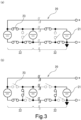
- Fig. 3 includes views, each of which schematically illustrates the configuration of the battery 20.
- the battery modules 21 and switching switches 23 are deformed.
- the plural battery modules 21 are configured to include plural ([number of the battery modules 21 - 1]) battery module pairs 22 that are electrically connected to each other via the switching switches 23.
- Each of the switching switches 23 is configured to be switched between ON/OFF on the basis of a command from the battery ECU 15.
- connection mode of some of the battery module pairs 22 can be set in series, and the connection mode of the rest of the battery module pairs 22 can be set in parallel.
- the battery ECU 15 and the battery 20 can change the connection mode of the battery module pairs 22 between in series and in parallel not only when the electric vehicle 1 is stopped or parked but also when the electric vehicle 1 is traveling.
- Fig. 4 is a cross-sectional view schematically illustrating the motor 40.
- a secondary conductor 65 and a resin 66 are not hatched.
- an air gap G is exaggerated in size.
- the motor 40 includes a rotary shaft 41, a rotor 60, and a stator 50.
- the motor 40 is mounted on the electric vehicle 1 in a manner to set the rotary shaft 41 to be substantially horizontal.
- the rotary shaft 41 is supported by a casing (not illustrated) of the motor 40 to be rotatable by a bearing (not illustrated).
- the rotary shaft 41 is formed in a cylindrical shape, and an internal space thereof constitutes a channel 42 through which a refrigerant for cooling each section of the motor 40 flows.
- a pump (not illustrated) is connected to one end of the channel 42, and the refrigerant is supplied by this pump.
- the rotor 60 is formed in a cylindrical shape whose inner diameter is slightly larger than an outer diameter of the rotary shaft 41.
- the rotor 60 is arranged on a radially outer side of the rotary shaft 41 and is attached to the rotary shaft 41 in an integrally rotatable manner therewith.
- the stator 50 is formed in a cylindrical shape, and is arranged on a radially outer side of the rotor 60 such that a center axis of the stator 50 matches a center axis of the rotary shaft 41.
- the rotor 60 is rotatably arranged in the stator 50 to be coaxial with the center axis of the stator 50.
- An inner diameter of the stator 50 and an outer diameter of the rotor 60 are set to such dimensions that, when the rotor 60 is arranged in the stator 50, an inner circumferential surface 51a of the stator 50 and an outer circumferential surface 61a of the rotor 60 oppose each other across the air gap G.
- a motor temperature sensor 43 detects a temperature of the motor 40
- the torque sensor 45 detects motor torque
- the rotation angle sensor 47 detects a rotation angle of the rotor 60.
- These motor temperature sensor 43, torque sensor 45, and rotation angle sensor 47 are electrically connected to the motor ECU 13 and output, to the motor ECU 13, a signal representing the detected temperature, a signal representing a magnitude of the motor torque, and a signal representing the rotation angle of the rotor 60, respectively.
- a drive current is supplied to the stator 50 from the battery 20 via the inverter 30 on the basis of a command from the motor ECU 13. Consequently, a rotating magnetic field is created in the stator 50, which in turn rotationally drives the rotor 60 and drives the front wheels 7 of the electric vehicle 1.
- the rotor 60 and the stator 50 will be described in detail.
- the rotor 60 has a rotor core 61, the plural secondary conductors 65 that are embedded in the rotor core 61, and plural (eight) permanent magnets 80 that are also embedded in the rotor core 61.
- the rotor core 61 is made of a magnetic material such as iron and has an inner prism section 61b and an outer cylindrical section 61c.
- the inner prism section 61b is formed in a prism shape whose outer shape is octagonal and inner shape is circular when seen in an axial direction.
- the outer cylindrical section 61c has eight blocks 69.
- Each of the blocks 69 is formed to have such a cross-sectional shape that a lower base 69b of an isosceles trapezoid is arcuate when seen in the axial direction.
- the arcuate lower base 69b of each of the blocks 69 is formed with eight groove strips 63, each of which extends toward an upper base 69a.
- the eight blocks 69 are combined such that the upper base 69a of each of the blocks 69 faces a radially inner side and that legs 69 oppose each other in a circumferential direction.
- the outer cylindrical section 61c has a cylindrical shape whose outer shape is circular and inner shape is octagonal.
- a space between two each of a circumferentially-opposing legs 69c also constitutes the groove strip 63.
- the 72 (8 blocks ⁇ 8 strips + 8 strips) groove strips 63 are formed at equally-spaced intervals in the circumferential direction.
- Each of the groove strips 63 has a rectangular cross section, extends over an entire axial length of the rotor core 61, and is recessed radially inward from the outer circumferential surface 61a of the rotor core 61.
- the 72 groove strips 63 each of which extends in the radial direction, are radiated when seen in the axial direction.
- a rotor shatterproof cover is attached to the outer circumferential surface 61a of the rotor core 61, in which the eight blocks 69 are combined.
- the permanent magnet 80 is formed in a plate shape that extends in the axial direction of the rotor 60 and has a rectangular cross section.
- Each of the eight permanent magnets 80 is embedded in the rotor core 61 in a manner to be sandwiched between an outer circumferential surface of the inner prism section 61b having the octagonal outer shape and the upper base 69a of respective one of the eight blocks 69.
- these eight permanent magnets 80 are arranged such that the permanent magnet 80, whose N pole indicated in black faces radially outward and S pole indicated in blank faces radially inward, and the permanent magnet 80, whose S pole faces radially outward and N pole faces radially inward, are alternately aligned in the circumferential direction.
- the permanent magnets 80 form eight poles.
- these eight permanent magnets 80 are integrated with the rotor core 61 by the resin 66 that is supplied through the groove strips 63, each of which is formed by the circumferentially-opposing legs 69.
- Each of the permanent magnets 80 is made of a ferrite magnet.
- a motor that uses a rare earth magnet such as neodymium as the permanent magnet has such concern that, when the permanent magnet reaches a high temperature (220°), the permanent magnet is permanently demagnetized by an antimagnetic field and loses a function as the magnet, which causes the motor to no longer function.
- the ferrite magnet is used as the permanent magnet 80, it is possible to suppress a reduction in motor output, which is caused by demagnetization of the permanent magnet 80 in a high-speed, high-load state.
- Fig. 5 is a perspective view schematically illustrating the secondary conductor 65.
- Fig. 5 in order to make the drawing easily viewable, only 4 of the 72 secondary conductors 65 are illustrated.
- Fig. 5 illustrates a rotation axis RA of the motor 40.
- Each of the secondary conductors 65 is made of a magnetic material such as copper and, as illustrated in Fig. 4 and Fig. 5 , formed in a rectangular plate shape that extends over an entire axial length of the rotor 60.
- Each of the 72 secondary conductors 65 is inserted in respective one of the groove strips 63 that are formed in the outer circumferential section of the rotor core 61.
- Fig. 4 illustrates the 72 groove strips 63 and the 72 secondary conductors 65.
- the number of the groove strips 63 and the number of the secondary conductors 65 are not limited thereto.
- each of the 72 secondary conductors 65 an end portion on one side (a left side in Fig. 5 ) in the axial direction (of the rotation axis RA) is coupled to a copper-made first end ring 67 (a shortening ring) by welding or the like, and an end portion on the other side (a right side in Fig. 5 ) in the axial direction is coupled to a copper-made second end ring 68 (a shortening ring) by welding or the like.
- the 72 secondary conductors 65 define a cage shape.
- the 72 secondary conductors 65 are electrically connected to each other via the first and second end rings 67, 68, just as described, and thereby form a closed circuit.
- each of the secondary conductors 65 crosses the magnetic field, an induced electromotive force is generated in the respective secondary conductor 65 due to electromagnetic induction.
- an induced current flows through each of the secondary conductors 65.
- an outer circumferential surface of each of the secondary conductors 65 is insulated.
- the stator 50 has a cylindrical stator core 51 and plural stator coils 55 as primary conductors.
- the stator core 51 may be formed by stacking and integrally coupling plural electromagnetic steel sheets, each of which is punched into a predetermined shape, for example, or may be formed of a powder magnetic body that is formed by subjecting magnetic powder to compression molding in a mold, for example.
- the stator core 51 has plural grooves referred to as slots 53. Each of the slots 53 extends radially outward from the inner circumferential surface 51a of the stator core 51, and the adjacent slots 53 separate from each other in a circumferential direction of the stator core 51.
- stator coils 55 are accommodated in each of the slots 53 and each wound by so-called distributed winding. These plural stator coils 55 are U-phase coils, a V-phase coils, and W-phase coils, for example. The stator coils 55 are each accommodated in the corresponding slot 53 to constitute 18 poles.
- the inverter 30 is configured to convert the direct current, which is supplied from the battery 20, to the alternating current and supply the alternating current to the motor 40 while converting regenerative electric power, which is generated by the motor 40, to DC power and supplying the DC power to the battery 20. In this way, the inverter 30 is configured to be able to charge the battery 20.
- the inverter 30 is electrically connected to the motor ECU 13, and controls the current supplied from the battery 20 on the basis of a command from the motor ECU 13. More specifically, the inverter 30 is configured to supply the alternating current, whose phases are each shifted by 120°, to the U-phase coils, the V-phase coils, and the W-phase coils.
- the alternating current is supplied from the inverter 30 to the stator coils 55, just as described, the 18 rotating magnetic fields are created in the stator 50 (the stator coils 55).
- the motor ECU 13 is configured to include a so-called microcomputer having, for example, a CPU, ROM, RAM, backup RAM, an input/output interface, and the like.
- the CPU executes various types of control by executing signal processing according to a program, which is stored in the ROM in advance, while using a temporary storage function of the RAM.
- the motor ECU 13 is connected to the ECU 11 via the CAN communication line, and is configured to output, to the ECU 11, a signal related to the temperature of the motor 40 received from the motor temperature sensor 43, a signal related to the motor torque received from the torque sensor 45, and a signal related to the rotation angle of the rotor 60 received from the rotation angle sensor 47. Then, the motor ECU 13 is configured to control the motor 40 via the inverter 30 such that the required torque for the motor 40, which is input from the ECU 11, is generated.
- the rotor 60 has not only the permanent magnet 80 but also the secondary conductor 65.
- the motor 40 can be rotationally driven in two different modes that are: a synchronous operation mode in which the rotor 60 is rotated by using a magnetic force of the permanent magnet 80; and the asynchronous operation mode in which the rotor 60 is rotated by using the induced current generated in the secondary conductor 65.
- the ECU 11, the motor ECU 13, and the inverter 30 control the rotating magnetic field by causing a flow of an input current of a predetermined phase, a predetermined advance angle, and a predetermined magnitude through the stator coil 55 on the basis of the rotation angle of the rotor 60 detected by the rotation angle sensor 47, and the like.
- the ECU 11, the motor ECU 13, and the inverter 30 are configured to execute mode switching control to switch between the synchronous operation mode and the asynchronous operation mode.
- the ECU 11, the motor ECU 13, and the inverter 30 in this embodiment correspond to the "control section capable of switching a drive mode of the motor between the synchronous operation mode, in which the rotor is rotated by using the magnetic force of the permanent magnet, and the asynchronous operation mode, in which the rotor is rotated by using the induced current generated in the secondary conductor".
- the ECU 11, the motor ECU 13, and the inverter 30 will also be referred to as the "ECU 11 and the like", and a description will be made on the synchronous operation mode and the asynchronous operation mode executed by the ECU 11 and the like.
- an angular velocity of the rotating magnetic field is synchronized with (made to match) a mechanical rotational speed of the rotor 60 through control of the rotating magnetic field by the ECU 11 and the like.
- the DC power that is supplied from the battery 20 is converted to AC power during rotation of the rotor 60.
- a steady current is generated in each phase.
- steady torque is generated by the rotating magnetic field and the permanent magnet 80.
- the induced current is generated when the secondary conductor 65 moves relative to the rotating magnetic field (crosses the magnetic field).
- the induced current does not flow through the secondary conductor 65. That is, in the synchronous operation mode, the secondary conductor 65 does not affect output torque of the motor 40.
- the asynchronous operation mode through the control of the rotating magnetic field by the ECU 11 and the like, a speed difference is generated between the angular velocity of the rotating magnetic field and the mechanical rotational speed of the rotor 60, so as to prevent matching (cause mismatching) therebetween.
- the DC power that is supplied from the battery 20 is converted to the AC power when the rotor 60 is either rotated or stationary.
- the steady torque is generated by the rotating magnetic field and the induced current generated in the secondary conductor 65.
- the angular velocity of the rotating magnetic field is always excessively higher or lower than the mechanical rotational speed of the rotor 60, and thus the permanent magnet 80 causes positive/negative torque fluctuations.
- the steady torque which is generated by the rotating magnetic field and the secondary conductor 65, fluctuates. That is, in the asynchronous operation mode, the permanent magnet 80 affects the output torque of the motor 40.
- the drive power is changed constantly due to the driving operation by the driver or the travel environment. Accordingly, when the required output for the motor 40 is changed, it is desired to switch the operation state of the motor 40, which is the drive source of the electric vehicle 1, in order for the motor 40 to generate the required output.
- the ECU 11 is configured to switch a drive mode of the motor 40 from the synchronous operation mode to the asynchronous operation mode on the basis of the required output for the motor 40.
- the ECU 11 estimates the required output (torque) for the motor 40 on the basis of the vehicle speed V detected by the vehicle speed sensor 74, the accelerator pedal depression amount detected by the accelerator pedal sensor 70, the location information received from the GPS receiver 75, the map database stored in the ROM, and the like. Then, in the case where the required torque is higher than allowable limit torque in the synchronous operation mode, the ECU 11 switches the drive mode of the motor 40 from the synchronous operation mode to the asynchronous operation mode.
- the ECU 11 since the ECU 11 switches the drive mode of the motor 40 from the synchronous operation mode to the asynchronous operation mode according to the required output for the motor 40, the characteristic of the motor 40 can be changed during travel of the electric vehicle 1 by such mode switching. In this way, it is possible to generate a wide range of the required output according to the driver's preference.
- the motor 40 includes both of the secondary conductor 65, in which the induced current is generated, and the permanent magnet 80.
- the motor 40 functions as an asynchronous motor, as described above, torque pulsation occurs due to the magnetic force of the inevitably existing permanent magnet 80. Thus, it is assumed that such torque pulsation is transmitted to a cabin and gives a sense of discomfort to the driver.
- the ECU 11 and the like are configured that, in the asynchronous operation mode, a current that generates torque in an opposite phase from a phase of the torque pulsation by the permanent magnets 80 is superimposed on the drive current generated by the motor 40, and then such a current is supplied to the stator coil 55 of the stator 50.
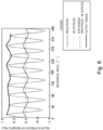
- Fig. 6 is a graph schematically illustrating the output torque of the motor 40 in the asynchronous operation mode.
- Fig. 7 is a graph schematically illustrating a state where an antiphase component is applied to the magnetic field created by the permanent magnet 80.
- Fig. 8 is a graph schematically illustrating the output torque of the motor 40 when the antiphase component is applied to the magnetic field created by the permanent magnet 80 in the asynchronous operation mode.
- a period of the magnetic field created by an 18-pole IM motor differs from a period of the magnetic field created by the PM motor (the synchronous motor) using the 8-pole permanent magnets 80.
- IM dotted line
- PM thin solid line
- a phase difference is generated therebetween.
- the output torque which is generated by the magnetic field combining those two magnetic fields (see a broken line in Fig. 6 ), is not the steady torque and fluctuates (pulsates) as indicated by a bold solid line in Fig. 6 .
- the output torque that is generated by the synthetic magnetic field is the steady torque as indicated by a bold solid line in Fig. 8 .
- the ECU 11 and the like are configured to allow the torque pulsation in a travel state that requires the relatively high drive torque in the asynchronous operation mode.
- the "travel state that requires the relatively high drive torque” means a case where the required torque for the motor 40 becomes higher than a predetermined value that is set in advance in a manner to correspond to a situation where the engine operation state is changed rapidly. Examples of such a situation include the time when the engine vehicle is accelerated rapidly and the time when the engine vehicle is started on the uphill road.
- the torque pulsation can be canceled out during normal time.
- the torque pulsation is allowed.
- the vibration of the motor 40 which is transmitted to the cabin, allows the driver to recognize that the vehicle is accelerated as desired by the driver himself/herself, for example.
- whether the driver prefers to cancel out the torque pulsation or allow the torque pulsation is input to the ECU 11 when the driver operates the selection switch 76 that is provided on an instrument panel (not illustrated), for example. Consequently, for example, when the driver operates the selection switch 76 to be ON, the antiphase component is applied to the magnetic field created by the permanent magnets 80, and the torque pulsation is thus canceled out. Meanwhile, when the driver operates the selection switch 76 to be OFF, the torque pulsation is allowed in the travel state that requires the relatively high drive torque.
- step S1 the ECU 11 reads the ON/OFF operation of the selection switch 76 by the driver. Then, the processing proceeds to step S2.
- step S2 the ECU 11 acquires the required torque for the motor 40 on the basis of the vehicle speed V, the accelerator pedal depression amount, the travel environment of the electric vehicle 1, and the like. Then, the processing proceeds to step S3.
- step S3 the ECU 11 and the like acquire a temperature (an actual operating temperature) of the permanent magnet 80 detected by the motor temperature sensor 43. Then, the processing proceeds to step S4.
- next step S4 the ECU 11 determines whether the required torque for the motor 40, which is acquired in step S2, is lower than the allowable limit torque in the synchronous operation mode. If it is determined YES in this step S4, the processing proceeds to step S5. On the other hand, if it is determined NO in this step S4, the processing proceeds to step S7. In next step S5, the ECU 11 determines whether the actual operating temperature of the permanent magnet 80, which is acquired in step S3, is lower than an allowable temperature of the permanent magnet 80. If it is determined YES in this step S5, the processing proceeds to step S6. On the other hand, if it is determined NO in this step S5, the processing proceeds to step S7.
- step S6 the ECU 11 and the like set the operation mode of the motor 40 to the synchronous operation mode, and thereafter the processing returns. Otherwise, the processing proceeds to step S7.
- step S7 the ECU 11 and the like set the operation mode of the motor 40 to the asynchronous operation mode, and then the processing proceeds to step S8.
- next step S8 the ECU 11 determines whether the operation of the selection switch 76, which is read in step S1, is the ON operation. If it is determined YES in this step S8, the processing proceeds to step S9, and the ECU 11 and the like superimpose the current, which generates the torque in the opposite phase from the phase of the torque pulsation by the permanent magnet 80, on the drive current of the motor 40. Then, the processing returns.
- step S8 if it is determined NO in step S8, that is, if the operation of the selection switch 76 is the OFF operation, the processing proceeds to step S10. Then, similar to step S9, the ECU 11 and the like superimpose the current, which generates the torque in the opposite phase from the phase of the torque pulsation by the permanent magnet 80, on the drive current of the motor 40. Thereafter, the processing proceeds to step S11.
- next step S11 the ECU 11 determines whether the required torque for the motor 40, which is acquired in step S2, exceeds a predetermined value that is set in advance. If it is determined NO in this step S11, the processing returns while the torque in the opposite phase from the phase of the torque pulsation by the permanent magnet 80 remains to be generated. On the other hand, it is determined YES in this step S11, the processing proceeds to step S12, and the ECU 11 and the like stop supplying the current, which generates the torque in the opposite phase from the phase of the torque pulsation by the permanent magnet 80. Then, the processing returns.
- the torque pulsation is canceled out in the asynchronous operation mode. Then, when the required torque for the motor 40 exceeds the predetermined value, the torque pulsation is allowed.
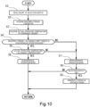
- the allowable limit torque may be set to satisfy the predetermined value ⁇ the allowable limit torque in the synchronous operation mode, for example. Then, as in a flowchart illustrated in Fig. 10 , in the case where the operation of the selection switch 76 is the OFF operation, the torque pulsation may be allowed thoroughly.
- steps S1' to S7' and S9' in Fig. 10 are the same procedure as steps S1 to S7 and S9 in Fig. 9 . Thus, the description thereon will not be made.
- the torque pulsation is allowed in such a travel state where the relatively high drive torque is required.
- the invention is not limited thereto.
- the torque pulsation may be amplified.
- the torque pulsation can easily be amplified, for example, by applying an in-phase component to the magnetic field created by the permanent magnets 80.
- the condition to allow the torque pulsation is set as the "travel state that requires the relatively high drive torque".
- the condition is not limited thereto.
- the condition to allow the torque pulsation may be set as a "travel state that requires relatively high regenerative torque", and an example of such a travel state is the time during rapid deceleration.
- the torque pulsation is allowed in the case where the required torque for the motor 40 is higher than the predetermined value.
- the invention is not limited thereto.
- the torque pulsation may be allowed in the case where an absolute value of a change amount (including positive and negative amounts) or a change speed (including positive and negative speeds) of the drive torque exceeds a predetermined change amount or a predetermined change speed, which is defined in advance.
- the eight permanent magnets 80 are embedded in the rotor core 61.
- the invention is not limited thereto.
- the 6 or less or 10 or more permanent magnets 80 may be embedded in the rotor core 61.
- the motor 40 is arranged in a front portion of the electric vehicle 1 in the vehicle front-rear direction, and the front wheels 7 are the drive wheels.
- the invention is not limited thereto.
- the motor 40 may be arranged in a rear portion of the electric vehicle 1 in the vehicle front-rear direction, and the rear wheels 8 may be the drive wheels.
- the characteristic of the motor can be changed according to the wide range of the required output.
- the invention is extremely beneficial when being applied to the vehicle drive system that includes the motor as the traveling drive source.
Landscapes
- Engineering & Computer Science (AREA)
- Power Engineering (AREA)
- Transportation (AREA)
- Mechanical Engineering (AREA)
- Life Sciences & Earth Sciences (AREA)
- Sustainable Development (AREA)
- Sustainable Energy (AREA)
- Electric Propulsion And Braking For Vehicles (AREA)
- Control Of Ac Motors In General (AREA)
- Permanent Magnet Type Synchronous Machine (AREA)
Abstract
[Task] To provide a vehicle drive system capable of changing a characteristic of a motor according to a wide range of required output in a vehicle that uses the motor as a traveling drive source.
[Solution] The vehicle drive system includes a motor that has a stator and a rotor provided in the stator and that drives a drive wheel of a vehicle by rotation of the rotor.
The rotor has: plural secondary conductors that are aligned in a circumferential direction in a radially outer portion; and plural permanent magnets that are aligned in the circumferential direction in a portion on a radially inner side of these plural secondary conductors. An ECU and a motor ECU capable of switching a drive mode of the motor between a synchronous operation mode and an asynchronous operation mode are further provided. Based on required output for the motor (S4), the ECU and the motor ECU are configured to switch the drive mode of the motor from the synchronous operation mode to the asynchronous operation mode (S7).
Description
- The present invention relates to a vehicle drive system and, in particular, to a vehicle drive system that is applied to a vehicle traveling by using a motor as a drive source. The present invention further relates to an electrical vehicle which comprises a vehicle drive system according the present invention.
- Conventionally, an electric vehicle that does not have an internal combustion engine (an engine) and travels by using an electric motor (a motor) as a drive source has been known.
- The motors are largely classified into a PM motor (a synchronous motor) that uses a magnetic force of a permanent magnet to rotate a rotor and an IM motor (an asynchronous motor) that uses an induced current generated in a conductor to rotate the rotor. The PM motor is frequently selected for the electric vehicle since the PM motor can be actuated at maximum torque instantaneously even in a low-speed range.
- An advantage of the PM motor is that the PM motor can be actuated at the maximum torque even in the low-speed range as described above. However, in a high-speed range, since a large back electromotive force is generated due to an effect of the permanent magnet, there is a disadvantage of reduced output.
- In order to eliminate the above disadvantage, for example, the following motor is disclosed in
Patent document 1. The motor includes a stator and a cage-shaped rotor, and a permanent magnet is embedded in the cage-shaped rotor. - [Patent document 1]
JP2000-178840A - By the way, since required drive power for the vehicle is changed rapidly due to a driving operation by a driver or travel environment, the motor that is used as the vehicle drive source is desired to have a characteristic capable of generating such required output.
- Accordingly, it is considered to apply, as the vehicle drive source, a motor that has characteristics of both the PM motor and the IM motor as in
Patent document 1. Then, while the motor performs synchronous operation in the low-speed range, the motor performs asynchronous operation in the high-speed range, so as to suppress an effect of the back electromotive force. - However, the motor disclosed in
Patent document 1 performs the asynchronous operation only until a rotation speed of the cage-shaped rotor reaches a synchronous speed or in case of emergency stop, and thus the synchronous operation is presupposed. For this reason, it is difficult for the motor disclosed inPatent document 1 to generate a wide range of the required output according to the driver's preference and the like. - The invention has been made in view of such a point and therefore has a purpose of providing a vehicle drive system capable of changing a characteristic of a motor according to a wide range of required output in a vehicle that uses the motor as a traveling drive source.
- In order to achieve the above purpose, in a vehicle drive system according to the invention, a drive mode of a motor is switched from a synchronous operation mode to an asynchronous operation mode according to required output during travel of a vehicle.
- More specifically, the invention provides the vehicle drive system including the motor that has a cylindrical stator and a cylindrical rotor rotatably provided in the stator to be coaxial with a center axis of the stator and that drives a drive wheel of the vehicle by rotation of the rotor.
- The rotor has: plural secondary conductors that extend in an axial direction and aligned in a circumferential direction in a radially outer portion; and plural permanent magnets that extend in the axial direction and aligned in the circumferential direction in a portion on a radially inner side of these plural secondary conductors. This vehicle drive system further includes: a control section capable of switching a drive mode of the motor between a synchronous operation mode in which the rotor is rotated by using a magnetic force of the permanent magnet; and an asynchronous operation mode in which the rotor is rotated by using an induced current generated in the secondary conductor. The control section is configured to switch the drive mode of the motor from the synchronous operation mode to the asynchronous operation mode on the basis of required output for the motor.
- With this configuration, since the control section switches the drive mode of the motor from the synchronous operation mode, in which the rotor is rotated by using the magnetic force of the permanent magnet, to the asynchronous operation mode, in which the rotor is rotated by using the induced current generated in the secondary conductor, according to the required output for the motor. Thus, the characteristic of the motor can be changed during travel of the vehicle by such mode switching. In this way, it is possible to generate a wide range of the required output according to a driver's preference.
- By the way, the motor includes both of the secondary conductor, in which the induced current is generated, and the permanent magnet. When the motor functions as an asynchronous motor, torque pulsation occurs due to a magnetic force of the inevitably existing permanent magnet. Thus, it is assumed that such torque pulsation is transmitted to a cabin and gives a sense of discomfort to the driver.
- Accordingly, in the vehicle drive system, in the asynchronous operation mode, the control section may be configured to superimpose a current, which generates torque in an opposite phase from a phase of the torque pulsation by the permanent magnet, on a drive current generated by the motor and supply such a current to a stator coil of the stator.
- With this configuration, since the control section superimposes the current, which generates the torque in the opposite phase from the phase of the torque pulsation by the permanent magnet, on the drive current of the motor, the torque pulsation by the permanent magnet in the asynchronous operation mode can be canceled out. Therefore, it is possible to suppress unpleasant vibration of the motor from being transmitted to the cabin.
- By the way, in an engine vehicle, engine vibration that is transmitted to the cabin is changed according to a difference in an engine operation state. Thus, many drivers recognize the engine operation state from such vibration transmitted to the cabin. On the contrary, in the vehicle that is driven by the motor generating less vibration than the engine, it is difficult for the driver to recognize the vibration of the motor. Thus, such a case is assumed that, when the driver who is accustomed to driving the engine vehicle drives the motor-driven vehicle, the driver cannot recognize the operation state from the vibration transmitted to the cabin and thus feels the sense of discomfort.
- In order to handle the above case, in the vehicle drive system, the control section may be configured to allow the torque pulsation in a travel state that requires relatively high drive torque in the asynchronous operation mode.
- With this configuration, in the travel state that requires the relatively high drive torque, such as the time when acceleration is requested, the torque pulsation is allowed. Thus, the vibration of the motor, which is transmitted to the cabin, allows the driver to recognize that the vehicle is accelerated as desired by the driver himself/herself, for example.
- As it has been described so far, the vehicle drive system according to the invention can change the characteristic of the motor according to a wide range of required output in the vehicle that uses the motor as a traveling drive source.
-
- [
Fig. 1] Fig. 1 is a plan view schematically illustrating a vehicle on which a vehicle drive system according to an embodiment of the invention is mounted. - [
Fig. 2] Fig. 2 is a block diagram schematically illustrating the vehicle drive system. - [
Fig. 3] Fig. 3 includes views, each of which schematically illustrates a configuration of a battery. - [
Fig. 4] Fig. 4 is a cross-sectional view schematically illustrating a motor. - [
Fig. 5] Fig. 5 is a perspective view schematically illustrating a secondary conductor. - [
Fig. 6] Fig. 6 is a graph schematically illustrating motor output torque in an asynchronous operation mode. - [
Fig. 7] Fig. 7 is a graph schematically illustrating a state where an antiphase component is applied to a magnetic field created by a permanent magnet. - [
Fig. 8] Fig. 8 is a graph schematically illustrating the motor output torque when the antiphase component is applied to the magnetic field created by the permanent magnet in an asynchronous operation mode. - [
Fig. 9] Fig. 9 is a flowchart illustrating an example of control that is executed by a control section. - [
Fig. 10] Fig. 10 is a flowchart illustrating another example of the control that is executed by the control section. - [Modes for Carrying Out the Invention]
- A description will hereinafter be made on a mode for carrying out the invention with reference to the drawings.
-
Fig. 1 is a plan view schematically illustrating avehicle 1 on which avehicle drive system 10 according to this embodiment is mounted.Fig. 1 indicates a front side Fw in a vehicle front-rear direction, a rear side Rr in the vehicle front-rear direction, a right side Rh in a vehicle width direction, and a left side Lf in the vehicle width direction. As illustrated inFig. 1 , thevehicle 1 includes abattery 20, aninverter 30, amotor 40, and various electronic control units (ECUs) 11, 13, 15 for controlling these components. Thesebattery 20, inverter 30,motor 40, andvarious ECUs vehicle drive system 10. - In this
vehicle 1, theinverter 30 converts a direct current supplied from thebattery 20 to an alternating current and supplies the alternating current to themotor 40, and themotor 40 is thereby rotationally driven. Torque generated by themotor 40, which is rotationally driven just as described, is reduced by areduction drive 5 and then output to adriveshaft 6. Consequently, a right and left pair of drive wheels (front wheels 7) is rotationally driven to cause rotation of driven wheels (rear wheels 8). In this way, thevehicle 1 travels. That is, thevehicle 1 is configured as an electric vehicle that travels by using themotor 40 as a drive source. Thus, hereinafter, thevehicle 1 will also be referred to as an "electric vehicle 1". - As illustrated in
Fig. 1 , theelectric vehicle 1 also includes ashifter 2 and apaddle switch 73 that is provided on asteering wheel 3. A signal corresponding to an operation of each of theseshifter 2 and paddleswitch 73 is input to theECU 11. Thiselectric vehicle 1 is not equipped with a transmission, which is normally mounted on an engine vehicle. However, when a driver operates any of theseshifter 2 and paddleswitch 73, a characteristic of themotor 40 is changed to enable "driving" that reflects the driver's preference. -
Fig. 2 is a diagram schematically illustrating thevehicle drive system 10. As illustrated inFig. 2 , thisvehicle drive system 10 includes theECU 11, themotor ECU 13, thebattery ECU 15, thebattery 20, theinverter 30, themotor 40, various sensors (including switches) 70, 71, 72, 73, 74, 76, and a Global Positioning System (GPS)receiver 75. Thevarious sensors electric vehicle 1, and the like. - The
ECU 11 is configured to include a so-called microcomputer having, for example, a central processing unit (CPU), read only memory (ROM) that stores a program executed by the CPU, a map, and the like in advance, random access memory (RAM) in which the CPU temporarily stores data when necessary, backup RAM that holds the data even when power is cut off, an input/output interface, and the like. The CPU executes various types of control by executing signal processing according to the program, which is stored in the ROM in advance, while using a temporary storage function of the RAM. - In addition, the
ECU 11 is connected to themotor ECU 13 and thebattery ECU 15 via a controller area network (CAN) communication line (not illustrated), can exchange information with each other as indicated by broken arrows inFig. 2 , and plays a role in integrating themotor ECU 13 and thebattery ECU 15. - Furthermore, as illustrated in
Fig. 2 , theECU 11 is electrically connected to theaccelerator pedal sensor 70, thebrake pedal sensor 71, theshift position sensor 72, thepaddle switch 73, thevehicle speed sensor 74, theGPS receiver 75, and theselection switch 76, and detection results and various types of information are input/transmitted to theECU 11 from these. - The
accelerator pedal sensor 70 is attached to an accelerator pedal (not illustrated), detects the accelerator pedal depression amount, and outputs a signal representing the detected accelerator pedal depression amount to theECU 11. Theaccelerator pedal sensor 70 may be configured to detect an accelerator pedal depression change amount (a change amount per unit time). - The
brake pedal sensor 71 is attached to a brake pedal (not illustrated), detects the brake pedal depression amount, and outputs a signal representing the detected brake pedal depression amount to theECU 11. Thebrake pedal sensor 71 may be configured to detect a brake pedal depression change amount (a change amount per unit time). - The
shift position sensor 72 is provided to each shift position in theshifter 2, detects which of a parking (P) range, a reverse (R) range, a drive (D) range, and a manual (M) range ashift lever 2a is located, and outputs a detection result to theECU 11. The P range, the R range, and the D range are arranged in a main gate 2b while the M range is arranged in a sub gate 2c. Furthermore, the sub gate 2c is a returnable gate with the M range being a reference position. Theshift position sensor 72 is configured to output, to theECU 11, a signal in any of five levels D--, D-, D, D+, D++ in response to the number of operations to move theshift lever 2a to the front in the vehicle front-rear direction (positive operations) or the number of operations to move theshift lever 2a to the rear in the vehicle front-rear direction (negative operations) performed by the driver. - The
paddle switch 73 is a returnable switch that is provided as a right and left pair on a back side (the front side in the vehicle front-rear direction) of thesteering wheel 3 and that can repeatedly be pulled toward the driver (the rear side in the vehicle front-rear direction) by the driver. The right and left pair of the paddle switches 73 is configured to output, to theECU 11, a signal in any of five levels D--, D-, D, D+, D++ in response to the number of operations to pull thepaddle switch 73 on the right side in the vehicle width direction toward the driver (positive operations) or the number of operations to pull thepaddle switch 73 on the left side in the vehicle width direction toward the driver (negative operations). - The ROM of the
ECU 11 stores required torque for themotor 40 that is set to be increased in an order of D--, D-, D, D+, D++. Then, theECU 11 controls themotor 40 in a manner to reflect the driver's intention that is expressed by the operation of theshift lever 2a or thepaddle switch 73. - The
vehicle speed sensor 74 is configured to detect the vehicle speed V of theelectric vehicle 1 on the basis of wheel rotational speeds of the drive wheels (the front wheels 7) and the like and output a signal representing the detected vehicle speed V to theECU 11. TheECU 11 is configured to control themotor 40 on the basis of the vehicle speed V detected by thevehicle speed sensor 74, and the like. - The
GPS receiver 75 measures a location of the electric vehicle 1 (for example, latitude and longitude of the electric vehicle 1) by receiving radio waves from plural GPS satellites, and transmits location information thereof to theECU 11. TheECU 11 is configured to acquire (recognize) surrounding travel environment of theelectric vehicle 1 on the basis of the location information received from theGPS receiver 75, a map database stored in the ROM, for example, and the like. More specifically, theECU 11 acquires information such as on whether theelectric vehicle 1 is presently traveling on a flat road, traveling on an uphill road, traveling on a downhill road, turning, traveling on a winding road, or traveling in an urban area. Here, when the information such as on whether theelectric vehicle 1 is presently traveling on the uphill road or the downhill road is to be acquired, the method for acquiring the surrounding travel environment is not limited thereto, and a gradient sensor (not illustrated) that detects a road surface gradient may be used. Theselection switch 76 will be described below. - The
battery 20 is configured as a battery pack in which plural electrically-connected battery modules 21 (seeFig. 3 ) are stacked and accommodated in a battery case (not illustrated). Each of thebattery modules 21 includes, as a main portion, plural battery cells (not illustrated), each of which is a lithium-ion secondary battery, a nickel-metal hydride secondary battery, or the like. In detail, each of thebattery modules 21 is a module that is formed by electrically connecting the plural battery cells. The battery cells and insulators (not illustrated) are alternately stacked in a manner to hold the insulator between two each of the battery cells. - As illustrated in
Fig. 2 , abattery temperature sensor 25, avoltage sensor 27, a state of charge (SOC)sensor 29, and the like are attached to thebattery 20. Thebattery temperature sensor 25 detects a temperature of thebattery 20. Thevoltage sensor 27 detects a voltage of thebattery 20. TheSOC sensor 29 detects an SOC of thebattery 20. Thesebattery temperature sensor 25,voltage sensor 27, andSOC sensor 29 are electrically connected to thebattery ECU 15 and configured to output a signal representing the detected temperature, a signal representing the detected voltage, and a signal representing the SOC to thebattery ECU 15, respectively. - Similar to the
ECU 11, thebattery ECU 15 is configured to include a so-called microcomputer having, for example, a CPU, ROM, RAM, backup RAM, an input/output interface, and the like. The CPU executes various types of control by executing signal processing according to a program, which is stored in the ROM in advance, while using a temporary storage function of the RAM. - As described above, the
battery ECU 15 is connected to theECU 11 via the CAN communication line, and is configured to output, to theECU 11, the signal related to the temperature of thebattery 20 received from thebattery temperature sensor 25, the signal related to the voltage of thebattery 20 received from thevoltage sensor 27, and the signal related to the SOC of thebattery 20 received from theSOC sensor 29. In addition, when the temperature of thebattery 20 is excessively low, regenerative charging capability is impaired. Meanwhile, when the temperature of thebattery 20 is excessively high, failure possibly occurs. Thus, thebattery ECU 15 is configured to adjust a flow rate of a battery coolant, and the like on the basis of the temperature of thebattery 20. -
Fig. 3 includes views, each of which schematically illustrates the configuration of thebattery 20. InFig. 3 , in order to make the drawing easily viewable, thebattery modules 21 and switchingswitches 23 are deformed. As illustrated inFig. 3 , theplural battery modules 21 are configured to include plural ([number of the battery modules 21 - 1]) battery module pairs 22 that are electrically connected to each other via the switching switches 23. Each of the switching switches 23 is configured to be switched between ON/OFF on the basis of a command from thebattery ECU 15. - With such a configuration, when the switching
switch 23 is switched by the command from thebattery ECU 15 as illustrated inFig. 3(a) , all of the plural battery modules 21 (the battery module pairs 22) can be connected in parallel in thebattery 20. Just as described, when all of theplural battery modules 21 are connected in parallel in thebattery 20, a supply voltage is relatively reduced, but a supply current can relatively be increased. - Meanwhile, when the switching
switch 23 is switched by the command from thebattery ECU 15 as illustrated inFig. 3 (b) , all of the plural battery modules 21 (the battery module pairs 22) can be connected in series in thebattery 20. Just as described, when all of theplural battery modules 21 are connected in series in thebattery 20, the supply current is relatively reduced, but the supply voltage can relatively be increased. - Although not illustrated, when the switching
switch 23 is switched by the command from thebattery ECU 15, a connection mode of some of the battery module pairs 22 can be set in series, and the connection mode of the rest of the battery module pairs 22 can be set in parallel. - The
battery ECU 15 and thebattery 20 can change the connection mode of the battery module pairs 22 between in series and in parallel not only when theelectric vehicle 1 is stopped or parked but also when theelectric vehicle 1 is traveling. -
Fig. 4 is a cross-sectional view schematically illustrating themotor 40. InFig. 4 , in order to make the drawing easily viewable, asecondary conductor 65 and aresin 66 are not hatched. In addition, inFig. 4 , in order to make the drawing easily viewable, an air gap G is exaggerated in size. As illustrated inFig. 4 , themotor 40 includes arotary shaft 41, arotor 60, and astator 50. Themotor 40 is mounted on theelectric vehicle 1 in a manner to set therotary shaft 41 to be substantially horizontal. - The
rotary shaft 41 is supported by a casing (not illustrated) of themotor 40 to be rotatable by a bearing (not illustrated). Therotary shaft 41 is formed in a cylindrical shape, and an internal space thereof constitutes achannel 42 through which a refrigerant for cooling each section of themotor 40 flows. A pump (not illustrated) is connected to one end of thechannel 42, and the refrigerant is supplied by this pump. - The
rotor 60 is formed in a cylindrical shape whose inner diameter is slightly larger than an outer diameter of therotary shaft 41. Therotor 60 is arranged on a radially outer side of therotary shaft 41 and is attached to therotary shaft 41 in an integrally rotatable manner therewith. Meanwhile, thestator 50 is formed in a cylindrical shape, and is arranged on a radially outer side of therotor 60 such that a center axis of thestator 50 matches a center axis of therotary shaft 41. In other words, therotor 60 is rotatably arranged in thestator 50 to be coaxial with the center axis of thestator 50. An inner diameter of thestator 50 and an outer diameter of therotor 60 are set to such dimensions that, when therotor 60 is arranged in thestator 50, an innercircumferential surface 51a of thestator 50 and an outercircumferential surface 61a of therotor 60 oppose each other across the air gap G. - In addition, as illustrated in
Fig. 2 , amotor temperature sensor 43, atorque sensor 45, arotation angle sensor 47, and the like are attached to themotor 40. Themotor temperature sensor 43 detects a temperature of themotor 40, thetorque sensor 45 detects motor torque, and therotation angle sensor 47 detects a rotation angle of therotor 60. Thesemotor temperature sensor 43,torque sensor 45, androtation angle sensor 47 are electrically connected to themotor ECU 13 and output, to themotor ECU 13, a signal representing the detected temperature, a signal representing a magnitude of the motor torque, and a signal representing the rotation angle of therotor 60, respectively. - In the thus-configured
motor 40, a drive current is supplied to thestator 50 from thebattery 20 via theinverter 30 on the basis of a command from themotor ECU 13. Consequently, a rotating magnetic field is created in thestator 50, which in turn rotationally drives therotor 60 and drives thefront wheels 7 of theelectric vehicle 1. Hereinafter, therotor 60 and thestator 50 will be described in detail. - As illustrated in
Fig. 4 , therotor 60 has arotor core 61, the pluralsecondary conductors 65 that are embedded in therotor core 61, and plural (eight)permanent magnets 80 that are also embedded in therotor core 61. - The
rotor core 61 is made of a magnetic material such as iron and has aninner prism section 61b and an outercylindrical section 61c. Theinner prism section 61b is formed in a prism shape whose outer shape is octagonal and inner shape is circular when seen in an axial direction. - The outer
cylindrical section 61c has eightblocks 69. Each of theblocks 69 is formed to have such a cross-sectional shape that alower base 69b of an isosceles trapezoid is arcuate when seen in the axial direction. In addition, the arcuatelower base 69b of each of theblocks 69 is formed with eight groove strips 63, each of which extends toward anupper base 69a. In the outercylindrical section 61c, the eightblocks 69 are combined such that theupper base 69a of each of theblocks 69 faces a radially inner side and thatlegs 69 oppose each other in a circumferential direction. In this way, when seen in the axial direction, the outercylindrical section 61c has a cylindrical shape whose outer shape is circular and inner shape is octagonal. In addition, when the eightblocks 69 are combined, a space between two each of a circumferentially-opposinglegs 69c also constitutes thegroove strip 63. In this way, in an outer circumferential section of therotor core 61, the 72 (8 blocks × 8 strips + 8 strips) groove strips 63 are formed at equally-spaced intervals in the circumferential direction. Each of the groove strips 63 has a rectangular cross section, extends over an entire axial length of therotor core 61, and is recessed radially inward from the outercircumferential surface 61a of therotor core 61. In other words, in the outer circumferential section of therotor core 61, the 72 groove strips 63, each of which extends in the radial direction, are radiated when seen in the axial direction. Although not illustrated, a rotor shatterproof cover is attached to the outercircumferential surface 61a of therotor core 61, in which the eightblocks 69 are combined. - The
permanent magnet 80 is formed in a plate shape that extends in the axial direction of therotor 60 and has a rectangular cross section. Each of the eightpermanent magnets 80 is embedded in therotor core 61 in a manner to be sandwiched between an outer circumferential surface of theinner prism section 61b having the octagonal outer shape and theupper base 69a of respective one of the eight blocks 69. As illustrated inFig. 4 , these eightpermanent magnets 80 are arranged such that thepermanent magnet 80, whose N pole indicated in black faces radially outward and S pole indicated in blank faces radially inward, and thepermanent magnet 80, whose S pole faces radially outward and N pole faces radially inward, are alternately aligned in the circumferential direction. In this way, thepermanent magnets 80 form eight poles. In addition, these eightpermanent magnets 80 are integrated with therotor core 61 by theresin 66 that is supplied through the groove strips 63, each of which is formed by the circumferentially-opposinglegs 69. - Each of the
permanent magnets 80 is made of a ferrite magnet. A motor that uses a rare earth magnet such as neodymium as the permanent magnet has such concern that, when the permanent magnet reaches a high temperature (220°), the permanent magnet is permanently demagnetized by an antimagnetic field and loses a function as the magnet, which causes the motor to no longer function. However, in this embodiment, since the ferrite magnet is used as thepermanent magnet 80, it is possible to suppress a reduction in motor output, which is caused by demagnetization of thepermanent magnet 80 in a high-speed, high-load state. -
Fig. 5 is a perspective view schematically illustrating thesecondary conductor 65. InFig. 5 , in order to make the drawing easily viewable, only 4 of the 72secondary conductors 65 are illustrated. In addition,Fig. 5 illustrates a rotation axis RA of themotor 40. Each of thesecondary conductors 65 is made of a magnetic material such as copper and, as illustrated inFig. 4 andFig. 5 , formed in a rectangular plate shape that extends over an entire axial length of therotor 60. Each of the 72secondary conductors 65 is inserted in respective one of the groove strips 63 that are formed in the outer circumferential section of therotor core 61. In this way, the 72secondary conductors 65 are aligned in the circumferential direction and radiated when seen in the axial direction. A gap between each of the groove strips 63 and each of thesecondary conductors 65 inserted in therespective groove strip 63 is filled with theresin 66 that is supplied by injection molding. In this way, therotor core 61 and thesecondary conductors 65 are integrated. Here,Fig. 4 illustrates the 72 groove strips 63 and the 72secondary conductors 65. However, these are merely illustrative, and the number of the groove strips 63 and the number of thesecondary conductors 65 are not limited thereto. - As illustrated in
Fig. 5 , in each of the 72secondary conductors 65, an end portion on one side (a left side inFig. 5 ) in the axial direction (of the rotation axis RA) is coupled to a copper-made first end ring 67 (a shortening ring) by welding or the like, and an end portion on the other side (a right side inFig. 5 ) in the axial direction is coupled to a copper-made second end ring 68 (a shortening ring) by welding or the like. In this way, the 72secondary conductors 65 define a cage shape. The 72secondary conductors 65 are electrically connected to each other via the first and second end rings 67, 68, just as described, and thereby form a closed circuit. When each of thesecondary conductors 65 crosses the magnetic field, an induced electromotive force is generated in the respectivesecondary conductor 65 due to electromagnetic induction. However, since the 72secondary conductors 65 form the closed circuit as described above, an induced current flows through each of thesecondary conductors 65. Here, in order to prevent current leakage, which possibly occurs when the induced currents flow in opposite directions through the circumferentially-adjacentsecondary conductors 65, as much as possible, an outer circumferential surface of each of thesecondary conductors 65 is insulated. - As illustrated in
Fig. 4 , thestator 50 has acylindrical stator core 51 and plural stator coils 55 as primary conductors. - The
stator core 51 may be formed by stacking and integrally coupling plural electromagnetic steel sheets, each of which is punched into a predetermined shape, for example, or may be formed of a powder magnetic body that is formed by subjecting magnetic powder to compression molding in a mold, for example. Thestator core 51 has plural grooves referred to asslots 53. Each of theslots 53 extends radially outward from the innercircumferential surface 51a of thestator core 51, and theadjacent slots 53 separate from each other in a circumferential direction of thestator core 51. - Plural stator coils 55 are accommodated in each of the
slots 53 and each wound by so-called distributed winding. These plural stator coils 55 are U-phase coils, a V-phase coils, and W-phase coils, for example. The stator coils 55 are each accommodated in thecorresponding slot 53 to constitute 18 poles. - The
inverter 30 is configured to convert the direct current, which is supplied from thebattery 20, to the alternating current and supply the alternating current to themotor 40 while converting regenerative electric power, which is generated by themotor 40, to DC power and supplying the DC power to thebattery 20. In this way, theinverter 30 is configured to be able to charge thebattery 20. In addition, theinverter 30 is electrically connected to themotor ECU 13, and controls the current supplied from thebattery 20 on the basis of a command from themotor ECU 13. More specifically, theinverter 30 is configured to supply the alternating current, whose phases are each shifted by 120°, to the U-phase coils, the V-phase coils, and the W-phase coils. When the alternating current is supplied from theinverter 30 to the stator coils 55, just as described, the 18 rotating magnetic fields are created in the stator 50 (the stator coils 55). - Similar to the
ECU 11 and thebattery ECU 15, themotor ECU 13 is configured to include a so-called microcomputer having, for example, a CPU, ROM, RAM, backup RAM, an input/output interface, and the like. The CPU executes various types of control by executing signal processing according to a program, which is stored in the ROM in advance, while using a temporary storage function of the RAM. - As described above, the
motor ECU 13 is connected to theECU 11 via the CAN communication line, and is configured to output, to theECU 11, a signal related to the temperature of themotor 40 received from themotor temperature sensor 43, a signal related to the motor torque received from thetorque sensor 45, and a signal related to the rotation angle of therotor 60 received from therotation angle sensor 47. Then, themotor ECU 13 is configured to control themotor 40 via theinverter 30 such that the required torque for themotor 40, which is input from theECU 11, is generated. - In the
vehicle drive system 10 according to this embodiment, as described above, therotor 60 has not only thepermanent magnet 80 but also thesecondary conductor 65. Thus, themotor 40 can be rotationally driven in two different modes that are: a synchronous operation mode in which therotor 60 is rotated by using a magnetic force of thepermanent magnet 80; and the asynchronous operation mode in which therotor 60 is rotated by using the induced current generated in thesecondary conductor 65. - More specifically, the
ECU 11, themotor ECU 13, and theinverter 30 control the rotating magnetic field by causing a flow of an input current of a predetermined phase, a predetermined advance angle, and a predetermined magnitude through thestator coil 55 on the basis of the rotation angle of therotor 60 detected by therotation angle sensor 47, and the like. In this way, theECU 11, themotor ECU 13, and theinverter 30 are configured to execute mode switching control to switch between the synchronous operation mode and the asynchronous operation mode. - In this way, in relation to the claims, the
ECU 11, themotor ECU 13, and theinverter 30 in this embodiment correspond to the "control section capable of switching a drive mode of the motor between the synchronous operation mode, in which the rotor is rotated by using the magnetic force of the permanent magnet, and the asynchronous operation mode, in which the rotor is rotated by using the induced current generated in the secondary conductor". Hereinafter, theECU 11, themotor ECU 13, and theinverter 30 will also be referred to as the "ECU 11 and the like", and a description will be made on the synchronous operation mode and the asynchronous operation mode executed by theECU 11 and the like. - In the synchronous operation mode, an angular velocity of the rotating magnetic field is synchronized with (made to match) a mechanical rotational speed of the
rotor 60 through control of the rotating magnetic field by theECU 11 and the like. In addition, in the synchronous operation mode, the DC power that is supplied from thebattery 20 is converted to AC power during rotation of therotor 60. Meanwhile, when therotor 60 is stationary, a steady current is generated in each phase. In the synchronous operation mode, steady torque is generated by the rotating magnetic field and thepermanent magnet 80. The induced current is generated when thesecondary conductor 65 moves relative to the rotating magnetic field (crosses the magnetic field). However, in the synchronous operation mode, in which the angular velocity of the rotating magnetic field matches the mechanical rotational speed of therotor 60, the induced current does not flow through thesecondary conductor 65. That is, in the synchronous operation mode, thesecondary conductor 65 does not affect output torque of themotor 40. - In the asynchronous operation mode, through the control of the rotating magnetic field by the
ECU 11 and the like, a speed difference is generated between the angular velocity of the rotating magnetic field and the mechanical rotational speed of therotor 60, so as to prevent matching (cause mismatching) therebetween. In addition, in the asynchronous operation mode, the DC power that is supplied from thebattery 20 is converted to the AC power when therotor 60 is either rotated or stationary. In the asynchronous operation mode, the steady torque is generated by the rotating magnetic field and the induced current generated in thesecondary conductor 65. In the asynchronous operation mode, the angular velocity of the rotating magnetic field is always excessively higher or lower than the mechanical rotational speed of therotor 60, and thus thepermanent magnet 80 causes positive/negative torque fluctuations. Then, due to an effect of the torque fluctuation, the steady torque, which is generated by the rotating magnetic field and thesecondary conductor 65, fluctuates. That is, in the asynchronous operation mode, thepermanent magnet 80 affects the output torque of themotor 40. - In the synchronous operation mode, similar to the normal PM motor, it is concerned that a large back electromotive force is generated due to an effect of the
permanent magnet 80 in a high-speed, high load range, resulting in the reduced output. - Meanwhile, the drive power is changed constantly due to the driving operation by the driver or the travel environment. Accordingly, when the required output for the
motor 40 is changed, it is desired to switch the operation state of themotor 40, which is the drive source of theelectric vehicle 1, in order for themotor 40 to generate the required output. - Thus, in the
vehicle drive system 10 according to this embodiment, theECU 11 is configured to switch a drive mode of themotor 40 from the synchronous operation mode to the asynchronous operation mode on the basis of the required output for themotor 40. - More specifically, the
ECU 11 estimates the required output (torque) for themotor 40 on the basis of the vehicle speed V detected by thevehicle speed sensor 74, the accelerator pedal depression amount detected by theaccelerator pedal sensor 70, the location information received from theGPS receiver 75, the map database stored in the ROM, and the like. Then, in the case where the required torque is higher than allowable limit torque in the synchronous operation mode, theECU 11 switches the drive mode of themotor 40 from the synchronous operation mode to the asynchronous operation mode. - As described above, since the
ECU 11 switches the drive mode of themotor 40 from the synchronous operation mode to the asynchronous operation mode according to the required output for themotor 40, the characteristic of themotor 40 can be changed during travel of theelectric vehicle 1 by such mode switching. In this way, it is possible to generate a wide range of the required output according to the driver's preference. - By the way, the
motor 40 includes both of thesecondary conductor 65, in which the induced current is generated, and thepermanent magnet 80. When themotor 40 functions as an asynchronous motor, as described above, torque pulsation occurs due to the magnetic force of the inevitably existingpermanent magnet 80. Thus, it is assumed that such torque pulsation is transmitted to a cabin and gives a sense of discomfort to the driver. - To handle such a problem, in the
vehicle drive system 10 according to this embodiment, theECU 11 and the like are configured that, in the asynchronous operation mode, a current that generates torque in an opposite phase from a phase of the torque pulsation by thepermanent magnets 80 is superimposed on the drive current generated by themotor 40, and then such a current is supplied to thestator coil 55 of thestator 50. -
Fig. 6 is a graph schematically illustrating the output torque of themotor 40 in the asynchronous operation mode.Fig. 7 is a graph schematically illustrating a state where an antiphase component is applied to the magnetic field created by thepermanent magnet 80.Fig. 8 is a graph schematically illustrating the output torque of themotor 40 when the antiphase component is applied to the magnetic field created by thepermanent magnet 80 in the asynchronous operation mode. - In the asynchronous operation mode, a period of the magnetic field created by an 18-pole IM motor (asynchronous motor) differs from a period of the magnetic field created by the PM motor (the synchronous motor) using the 8-pole
permanent magnets 80. In other words, there is a period difference between these magnetic fields. Thus, as it is understood from a comparison between a dotted line (IM) and a thin solid line (PM) inFig. 6 , a phase difference is generated therebetween. Thus, the output torque, which is generated by the magnetic field combining those two magnetic fields (see a broken line inFig. 6 ), is not the steady torque and fluctuates (pulsates) as indicated by a bold solid line inFig. 6 . - Meanwhile, as illustrated in
Fig. 7 , when an antiphase component IPC (a one-dot chain line inFig. 7 ) is applied to the magnetic field (a thin sold line inFig. 7 ) created by the eight-polepermanent magnets 80, the magnetic field created by the eight-polepermanent magnets 8 is canceled out in the control due to a principle of superimposition, and relative strength of a magnetic field created by a synthetic component SC (a two-dot chain line inFig. 7 ) of a phase component of the magnetic field created by the eight-polepermanent magnets 80 and the antiphase component IPC becomes 0 (zero). - Accordingly, in the asynchronous operation mode, when the antiphase component is applied to the magnetic field created by the
permanent magnets 80, only the magnetic field by the 18-pole IM motor is generated, despite presence of thepermanent magnets 80. As a result, the output torque that is generated by the synthetic magnetic field is the steady torque as indicated by a bold solid line inFig. 8 . - Thus, when the
ECU 11 and the like superimpose the current, which generates the torque in the opposite phase from the phase of the torque pulsation by thepermanent magnet 80, on the drive current of themotor 40, the torque pulsation by thepermanent magnets 80 in the asynchronous operation mode can be canceled out. Therefore, it is possible to suppress unpleasant vibration of themotor 40 from being transmitted to the cabin. - Meanwhile, in the engine vehicle, engine vibration that is transmitted to the cabin is changed according to a difference in an engine operation state. Thus, many drivers recognize the engine operation state from such vibration transmitted to the cabin. On the contrary, in the vehicle that is driven by the
motor 40, it is difficult for the driver to recognize the vibration of themotor 40 in comparison with the vibration of the engine. Thus, such a case is assumed that, when the driver who is accustomed to driving the engine vehicle drives the motor-driven vehicle, the driver cannot recognize the operation state from the vibration transmitted to the cabin and thus feels the sense of discomfort. - In order to handle the above case, in the
vehicle drive system 10 according to this embodiment, theECU 11 and the like are configured to allow the torque pulsation in a travel state that requires the relatively high drive torque in the asynchronous operation mode. - The "travel state that requires the relatively high drive torque" means a case where the required torque for the
motor 40 becomes higher than a predetermined value that is set in advance in a manner to correspond to a situation where the engine operation state is changed rapidly. Examples of such a situation include the time when the engine vehicle is accelerated rapidly and the time when the engine vehicle is started on the uphill road. - In the case where the
ECU 11 and the like are configured as described above, for example, the torque pulsation can be canceled out during normal time. In addition, in the travel state that requires the relatively high drive torque, such as the time when the acceleration is requested, in other words, in the case where the required torque for themotor 40 is higher than the predetermined value, the torque pulsation is allowed. Thus, the vibration of themotor 40, which is transmitted to the cabin, allows the driver to recognize that the vehicle is accelerated as desired by the driver himself/herself, for example. - Here, whether the driver prefers to cancel out the torque pulsation or allow the torque pulsation is input to the
ECU 11 when the driver operates theselection switch 76 that is provided on an instrument panel (not illustrated), for example. Consequently, for example, when the driver operates theselection switch 76 to be ON, the antiphase component is applied to the magnetic field created by thepermanent magnets 80, and the torque pulsation is thus canceled out. Meanwhile, when the driver operates theselection switch 76 to be OFF, the torque pulsation is allowed in the travel state that requires the relatively high drive torque. - Next, a description will be made on an example of control, which is executed by the
ECU 11 and the like, with reference to a flowchart illustrated inFig. 9 . - First, in step S1, the
ECU 11 reads the ON/OFF operation of theselection switch 76 by the driver. Then, the processing proceeds to step S2. - In next step S2, the
ECU 11 acquires the required torque for themotor 40 on the basis of the vehicle speed V, the accelerator pedal depression amount, the travel environment of theelectric vehicle 1, and the like. Then, the processing proceeds to step S3. - In next step S3, the
ECU 11 and the like acquire a temperature (an actual operating temperature) of thepermanent magnet 80 detected by themotor temperature sensor 43. Then, the processing proceeds to step S4. - In next step S4, the
ECU 11 determines whether the required torque for themotor 40, which is acquired in step S2, is lower than the allowable limit torque in the synchronous operation mode. If it is determined YES in this step S4, the processing proceeds to step S5. On the other hand, if it is determined NO in this step S4, the processing proceeds to step S7. In next step S5, theECU 11 determines whether the actual operating temperature of thepermanent magnet 80, which is acquired in step S3, is lower than an allowable temperature of thepermanent magnet 80. If it is determined YES in this step S5, the processing proceeds to step S6. On the other hand, if it is determined NO in this step S5, the processing proceeds to step S7. That is, only in the case where the required torque is lower than the allowable limit torque in the synchronous operation mode and the actual operating temperature is lower than the allowable temperature, the processing proceeds to step S6. Then, theECU 11 and the like set the operation mode of themotor 40 to the synchronous operation mode, and thereafter the processing returns. Otherwise, the processing proceeds to step S7. - In next step S7, the
ECU 11 and the like set the operation mode of themotor 40 to the asynchronous operation mode, and then the processing proceeds to step S8. - In next step S8, the
ECU 11 determines whether the operation of theselection switch 76, which is read in step S1, is the ON operation. If it is determined YES in this step S8, the processing proceeds to step S9, and theECU 11 and the like superimpose the current, which generates the torque in the opposite phase from the phase of the torque pulsation by thepermanent magnet 80, on the drive current of themotor 40. Then, the processing returns. - On the other hand, if it is determined NO in step S8, that is, if the operation of the
selection switch 76 is the OFF operation, the processing proceeds to step S10. Then, similar to step S9, theECU 11 and the like superimpose the current, which generates the torque in the opposite phase from the phase of the torque pulsation by thepermanent magnet 80, on the drive current of themotor 40. Thereafter, the processing proceeds to step S11. - In next step S11, the
ECU 11 determines whether the required torque for themotor 40, which is acquired in step S2, exceeds a predetermined value that is set in advance. If it is determined NO in this step S11, the processing returns while the torque in the opposite phase from the phase of the torque pulsation by thepermanent magnet 80 remains to be generated. On the other hand, it is determined YES in this step S11, the processing proceeds to step S12, and theECU 11 and the like stop supplying the current, which generates the torque in the opposite phase from the phase of the torque pulsation by thepermanent magnet 80. Then, the processing returns. - In the example illustrated in
Fig. 9 , in the case where the operation of theselection switch 76 is the OFF operation, basically, the torque pulsation is canceled out in the asynchronous operation mode. Then, when the required torque for themotor 40 exceeds the predetermined value, the torque pulsation is allowed. However, the allowable limit torque may be set to satisfy the predetermined value ≈ the allowable limit torque in the synchronous operation mode, for example. Then, as in a flowchart illustrated inFig. 10 , in the case where the operation of theselection switch 76 is the OFF operation, the torque pulsation may be allowed thoroughly. - More specifically, in the flowchart of
Fig. 10 , if it is determined NO in step S8', that is, if the operation of theselection switch 76 is the OFF operation, the processing may return as it is (without canceling out the torque pulsation). Here, steps S1' to S7' and S9' inFig. 10 are the same procedure as steps S1 to S7 and S9 inFig. 9 . Thus, the description thereon will not be made. - The invention is not limited to the embodiment and can be carried out in various modes without departing from the spirit and main features thereof.
- In the above embodiment, in the case where the driver performs the OFF operation of the
selection switch 76, the torque pulsation is allowed in such a travel state where the relatively high drive torque is required. However, the invention is not limited thereto. For example, in the travel state where the relatively high drive torque is required, the torque pulsation may be amplified. In this case, the torque pulsation can easily be amplified, for example, by applying an in-phase component to the magnetic field created by thepermanent magnets 80. - In the above embodiment, the condition to allow the torque pulsation is set as the "travel state that requires the relatively high drive torque". However, the condition is not limited thereto. The condition to allow the torque pulsation may be set as a "travel state that requires relatively high regenerative torque", and an example of such a travel state is the time during rapid deceleration.
- In the above embodiment, the torque pulsation is allowed in the case where the required torque for the
motor 40 is higher than the predetermined value. However, the invention is not limited thereto. For example, the torque pulsation may be allowed in the case where an absolute value of a change amount (including positive and negative amounts) or a change speed (including positive and negative speeds) of the drive torque exceeds a predetermined change amount or a predetermined change speed, which is defined in advance. - In the above embodiment, the eight
permanent magnets 80 are embedded in therotor core 61. However, the invention is not limited thereto. The 6 or less or 10 or morepermanent magnets 80 may be embedded in therotor core 61. - In the above embodiment, the
motor 40 is arranged in a front portion of theelectric vehicle 1 in the vehicle front-rear direction, and thefront wheels 7 are the drive wheels. However, the invention is not limited thereto. For example, themotor 40 may be arranged in a rear portion of theelectric vehicle 1 in the vehicle front-rear direction, and therear wheels 8 may be the drive wheels. - As described above, the above-described embodiment is merely illustrative in all respect and thus should not be construed in a restrictive manner. Furthermore, modifications and changes that fall within equivalents of the claims fall within the scope of the invention.
- According to the invention, the characteristic of the motor can be changed according to the wide range of the required output. Thus, the invention is extremely beneficial when being applied to the vehicle drive system that includes the motor as the traveling drive source.
-
- 1:
- VEHICLE
- 7:
- FRONT WHEEL (DRIVE WHEEL)
- 10:
- VEHICLE DRIVE SYSTEM
- 11:
- ECU (CONTROL SECTION)
- 13:
- MOTOR ECU (CONTROL SECTION)
- 30:
- INVERTER (CONTROL SECTION)
- 40:
- MOTOR
- 50:
- STATOR
- 55:
- STATOR COIL
- 60:
- ROTOR
- 61c:
- OUTER CYLINDRICAL SECTION (RADIALLY OUTER PORTION)
- 65:
- SECONDARY CONDUCTOR
- 80:
- PERMANENT MAGNET
Claims (15)
- A vehicle drive system (10) comprising:a motor (40) that has a cylindrical stator (50) and a cylindrical rotor (60) rotatably provided in the stator (50) to be coaxial with a center axis of the stator (50) and that drives a drive wheel (7) of a vehicle (1) by rotation of the rotor (60),the rotor (60) having: plural secondary conductors (65) that extend in an axial direction and aligned in a circumferential direction in a radially outer portion (61c); and plural permanent magnets (80) that extend in the axial direction and aligned in the circumferential direction in a portion on a radially inner side of these plural secondary conductors (65), and further comprising:a control section (11) capable of switching a drive mode of the motor (40) between a synchronous operation mode in which the rotor (60) is rotated by using a magnetic force of the permanent magnet (80); and an asynchronous operation mode in which the rotor (60) is rotated by using an induced current generated in the secondary conductor (65), whereinthe control section (11) is configured to switch the drive mode of the motor (40) from the synchronous operation mode to the asynchronous operation mode on the basis of required output for the motor (40).
- The vehicle drive system (10) according to claim 1, wherein
in the asynchronous operation mode, the control section (11) is configured to superimpose a current, which generates torque in an opposite phase from a phase of torque pulsation by the permanent magnet (80), on a drive current generated by the motor (40) and supply such a current to a stator coil of the stator (50). - The vehicle drive system (10) according to claim 1 or 2, wherein
the control section (11) is configured to allow the torque pulsation in a travel state that requires relatively high drive torque in the asynchronous operation mode. - The vehicle drive system (10) according to any one of the preceding claims, wherein the control section (11) is configured to switch the drive mode of the motor (40) from the synchronous operation mode to the asynchronous operation during travel.
- The vehicle drive system (10) according to any one of the preceding claims, wherein the vehicle drive system (10) comprises the control section (11), an motor control section (13) and an inverter (30) which are configured to control a rotating magnetic field by causing a flow of an input current of a predetermined phase, a predetermined advance angle, and a predetermined magnitude through the stator coil (55).
- The vehicle drive system (10) according to claim 5, wherein the flow of an input current is controlled on the basis of the rotation angle of a rotor (60) detected by a rotation angle sensor (47).
- The vehicle drive system (10) according to any one of the preceding claims, wherein the vehicle drive system (10) is configured that in the synchronous operation mode, an angular velocity of the rotating magnetic field is synchronized with a mechanical rotational speed of the rotor (60) through control of a rotating magnetic field by the control section (11) .
- The vehicle drive system (10) according to any one of the preceding claims, wherein the vehicle drive system (10) is configured in the asynchronous operation mode, through the control of the rotating magnetic field by the control section (11), to generate a speed difference between the angular velocity of the rotating magnetic field and the mechanical rotational speed of the rotor (60), so as to prevent matching therebetween.
- The vehicle drive system (10) according to any one of the preceding claims, wherein the control section (11) is configured to estimate the required output (torque) for the motor (40).
- The vehicle drive system (10) according to claim 9, wherein said estimation is performed on the basis of one or more of:
the vehicle speed (V) detected by a vehicle speed sensor (74), the accelerator pedal depression amount detected by a accelerator pedal sensor (70), the location information received from a GPS receiver (75), the map database stored in a ROM. - The vehicle drive system (10) according to any one of the preceding claims, wherein the permanent magnet (80) is a ferrite magnet.
- The vehicle drive system (10) according to any one of the preceding claims, wherein the rotor (60) has a rotor core (61), wherein the plural secondary conductors (65) are embedded in the rotor core (61), and the plural permanent magnets (80) are also embedded in the rotor core (61).
- The vehicle drive system (10) according to any one of the preceding claims, wherein the rotor (60) has eight permanent magnets (80).
- The vehicle drive system (10) according to any one of the preceding claims, wherein the permanent magnet (80) is formed in a plate shape that extends in the axial direction of the rotor (60) and has a rectangular cross section.
- An electrical vehicle (1) comprising a vehicle drive system (10) according to any one of the preceding claims.
Applications Claiming Priority (1)
| Application Number | Priority Date | Filing Date | Title |
|---|---|---|---|
| JP2023080424A JP2024164733A (en) | 2023-05-15 | 2023-05-15 | Vehicle Drive System |
Publications (1)
| Publication Number | Publication Date |
|---|---|
| EP4464538A1 true EP4464538A1 (en) | 2024-11-20 |
Family
ID=91067295
Family Applications (1)
| Application Number | Title | Priority Date | Filing Date |
|---|---|---|---|
| EP24174727.8A Pending EP4464538A1 (en) | 2023-05-15 | 2024-05-08 | Vehicle drive system |
Country Status (4)
| Country | Link |
|---|---|
| US (1) | US20240388186A1 (en) |
| EP (1) | EP4464538A1 (en) |
| JP (1) | JP2024164733A (en) |
| CN (1) | CN118953047A (en) |
Families Citing this family (1)
| Publication number | Priority date | Publication date | Assignee | Title |
|---|---|---|---|---|
| KR20250112995A (en) * | 2024-01-18 | 2025-07-25 | 현대자동차주식회사 | Motor control method |
Citations (4)
| Publication number | Priority date | Publication date | Assignee | Title |
|---|---|---|---|---|
| JP2000178840A (en) | 1998-12-16 | 2000-06-27 | Shinko Electric Co Ltd | Spinning machine |
| JP4655786B2 (en) * | 2005-07-06 | 2011-03-23 | パナソニック株式会社 | Hermetic compressor |
| US20150236575A1 (en) * | 2014-02-18 | 2015-08-20 | Raymond James Walsh | Magnetic shield for hybrid motors |
| WO2017090159A1 (en) * | 2015-11-26 | 2017-06-01 | 株式会社安川電機 | Rotary electric machine |
-
2023
- 2023-05-15 JP JP2023080424A patent/JP2024164733A/en active Pending
-
2024
- 2024-04-08 CN CN202410412951.3A patent/CN118953047A/en active Pending
- 2024-05-08 EP EP24174727.8A patent/EP4464538A1/en active Pending
- 2024-05-10 US US18/660,373 patent/US20240388186A1/en active Pending
Patent Citations (4)
| Publication number | Priority date | Publication date | Assignee | Title |
|---|---|---|---|---|
| JP2000178840A (en) | 1998-12-16 | 2000-06-27 | Shinko Electric Co Ltd | Spinning machine |
| JP4655786B2 (en) * | 2005-07-06 | 2011-03-23 | パナソニック株式会社 | Hermetic compressor |
| US20150236575A1 (en) * | 2014-02-18 | 2015-08-20 | Raymond James Walsh | Magnetic shield for hybrid motors |
| WO2017090159A1 (en) * | 2015-11-26 | 2017-06-01 | 株式会社安川電機 | Rotary electric machine |
Also Published As
| Publication number | Publication date |
|---|---|
| US20240388186A1 (en) | 2024-11-21 |
| JP2024164733A (en) | 2024-11-27 |
| CN118953047A (en) | 2024-11-15 |
Similar Documents
| Publication | Publication Date | Title |
|---|---|---|
| Momen et al. | Electrical propulsion system design of Chevrolet Bolt battery electric vehicle | |
| US7569966B2 (en) | Rotating electrical machine and coil | |
| EP2139106B1 (en) | Controller for motor | |
| EP0954092B1 (en) | Drive control apparatus for electric synchronous machine having field winding | |
| EP1981162A2 (en) | Controller of electric motor | |
| JP2002262534A (en) | Rotating electric machine and vehicle equipped with it | |
| US20220329178A1 (en) | Apparatus for controlling variable magnetic flux motor | |
| JPH07212915A (en) | Control method of electric motor for driving electric vehicle | |
| US20240388186A1 (en) | Vehicle drive system | |
| CN110194063B (en) | Drive motor, electric vehicle, and control method of drive motor | |
| EP4465508B1 (en) | DRIVE SYSTEM FOR A VEHICLE | |
| EP4465491B1 (en) | Vehicle drive system | |
| JP6497231B2 (en) | Motor control device | |
| An et al. | Permanent magnet synchronous machine design for hybrid electric cars with double e-motor and range extender | |
| EP4470820A1 (en) | Vehicle drive system | |
| EP4467385A1 (en) | Vehicle drive system | |
| Barcaro et al. | Performance evaluation of an integrated starter alternator using an interior permanent magnet machine | |
| US10819267B2 (en) | Controller for switched reluctance motor | |
| JP2008079420A (en) | Electric car | |
| Jurca et al. | Performance Analysis of an Integrated Starter-Alternator-Booster for Hybrid Electric Vehicles | |
| WO2024084891A1 (en) | Control devices and program | |
| JP3173396B2 (en) | Power output device and control method thereof | |
| JP2024130552A (en) | Motor Control Systems | |
| CN121840948A (en) | Variable pole permanent magnet machine | |
| Sgarbossa et al. | Performance evaluation of an integrated starter alternator using an interior permanent magnet machine |
Legal Events
| Date | Code | Title | Description |
|---|---|---|---|
| PUAI | Public reference made under article 153(3) epc to a published international application that has entered the european phase |
Free format text: ORIGINAL CODE: 0009012 |
|
| STAA | Information on the status of an ep patent application or granted ep patent |
Free format text: STATUS: THE APPLICATION HAS BEEN PUBLISHED |
|
| AK | Designated contracting states |
Kind code of ref document: A1 Designated state(s): AL AT BE BG CH CY CZ DE DK EE ES FI FR GB GR HR HU IE IS IT LI LT LU LV MC ME MK MT NL NO PL PT RO RS SE SI SK SM TR |
|
| STAA | Information on the status of an ep patent application or granted ep patent |
Free format text: STATUS: REQUEST FOR EXAMINATION WAS MADE |
|
| 17P | Request for examination filed |
Effective date: 20250331 |