EP4464537A1 - Motor torque control method and apparatus, electronic device, and vehicle - Google Patents
Motor torque control method and apparatus, electronic device, and vehicle Download PDFInfo
- Publication number
- EP4464537A1 EP4464537A1 EP23752238.8A EP23752238A EP4464537A1 EP 4464537 A1 EP4464537 A1 EP 4464537A1 EP 23752238 A EP23752238 A EP 23752238A EP 4464537 A1 EP4464537 A1 EP 4464537A1
- Authority
- EP
- European Patent Office
- Prior art keywords
- torque
- wheel
- working condition
- vehicle
- motor
- Prior art date
- Legal status (The legal status is an assumption and is not a legal conclusion. Google has not performed a legal analysis and makes no representation as to the accuracy of the status listed.)
- Pending
Links
Images



Classifications
-
- B—PERFORMING OPERATIONS; TRANSPORTING
- B60—VEHICLES IN GENERAL
- B60L—PROPULSION OF ELECTRICALLY-PROPELLED VEHICLES; SUPPLYING ELECTRIC POWER FOR AUXILIARY EQUIPMENT OF ELECTRICALLY-PROPELLED VEHICLES; ELECTRODYNAMIC BRAKE SYSTEMS FOR VEHICLES IN GENERAL; MAGNETIC SUSPENSION OR LEVITATION FOR VEHICLES; MONITORING OPERATING VARIABLES OF ELECTRICALLY-PROPELLED VEHICLES; ELECTRIC SAFETY DEVICES FOR ELECTRICALLY-PROPELLED VEHICLES
- B60L15/00—Methods, circuits, or devices for controlling the traction-motor speed of electrically-propelled vehicles
- B60L15/20—Methods, circuits, or devices for controlling the traction-motor speed of electrically-propelled vehicles for control of the vehicle or its driving motor to achieve a desired performance, e.g. speed, torque, programmed variation of speed
-
- B—PERFORMING OPERATIONS; TRANSPORTING
- B60—VEHICLES IN GENERAL
- B60L—PROPULSION OF ELECTRICALLY-PROPELLED VEHICLES; SUPPLYING ELECTRIC POWER FOR AUXILIARY EQUIPMENT OF ELECTRICALLY-PROPELLED VEHICLES; ELECTRODYNAMIC BRAKE SYSTEMS FOR VEHICLES IN GENERAL; MAGNETIC SUSPENSION OR LEVITATION FOR VEHICLES; MONITORING OPERATING VARIABLES OF ELECTRICALLY-PROPELLED VEHICLES; ELECTRIC SAFETY DEVICES FOR ELECTRICALLY-PROPELLED VEHICLES
- B60L3/00—Electric devices on electrically-propelled vehicles for safety purposes; Monitoring operating variables, e.g. speed, deceleration or energy consumption
- B60L3/10—Indicating wheel slip ; Correction of wheel slip
- B60L3/102—Indicating wheel slip ; Correction of wheel slip of individual wheels
-
- B—PERFORMING OPERATIONS; TRANSPORTING
- B60—VEHICLES IN GENERAL
- B60L—PROPULSION OF ELECTRICALLY-PROPELLED VEHICLES; SUPPLYING ELECTRIC POWER FOR AUXILIARY EQUIPMENT OF ELECTRICALLY-PROPELLED VEHICLES; ELECTRODYNAMIC BRAKE SYSTEMS FOR VEHICLES IN GENERAL; MAGNETIC SUSPENSION OR LEVITATION FOR VEHICLES; MONITORING OPERATING VARIABLES OF ELECTRICALLY-PROPELLED VEHICLES; ELECTRIC SAFETY DEVICES FOR ELECTRICALLY-PROPELLED VEHICLES
- B60L3/00—Electric devices on electrically-propelled vehicles for safety purposes; Monitoring operating variables, e.g. speed, deceleration or energy consumption
- B60L3/10—Indicating wheel slip ; Correction of wheel slip
- B60L3/104—Indicating wheel slip ; Correction of wheel slip by indirect measurement of vehicle speed
-
- B—PERFORMING OPERATIONS; TRANSPORTING
- B60—VEHICLES IN GENERAL
- B60L—PROPULSION OF ELECTRICALLY-PROPELLED VEHICLES; SUPPLYING ELECTRIC POWER FOR AUXILIARY EQUIPMENT OF ELECTRICALLY-PROPELLED VEHICLES; ELECTRODYNAMIC BRAKE SYSTEMS FOR VEHICLES IN GENERAL; MAGNETIC SUSPENSION OR LEVITATION FOR VEHICLES; MONITORING OPERATING VARIABLES OF ELECTRICALLY-PROPELLED VEHICLES; ELECTRIC SAFETY DEVICES FOR ELECTRICALLY-PROPELLED VEHICLES
- B60L3/00—Electric devices on electrically-propelled vehicles for safety purposes; Monitoring operating variables, e.g. speed, deceleration or energy consumption
- B60L3/10—Indicating wheel slip ; Correction of wheel slip
- B60L3/106—Indicating wheel slip ; Correction of wheel slip for maintaining or recovering the adhesion of the drive wheels
-
- B—PERFORMING OPERATIONS; TRANSPORTING
- B60—VEHICLES IN GENERAL
- B60L—PROPULSION OF ELECTRICALLY-PROPELLED VEHICLES; SUPPLYING ELECTRIC POWER FOR AUXILIARY EQUIPMENT OF ELECTRICALLY-PROPELLED VEHICLES; ELECTRODYNAMIC BRAKE SYSTEMS FOR VEHICLES IN GENERAL; MAGNETIC SUSPENSION OR LEVITATION FOR VEHICLES; MONITORING OPERATING VARIABLES OF ELECTRICALLY-PROPELLED VEHICLES; ELECTRIC SAFETY DEVICES FOR ELECTRICALLY-PROPELLED VEHICLES
- B60L3/00—Electric devices on electrically-propelled vehicles for safety purposes; Monitoring operating variables, e.g. speed, deceleration or energy consumption
- B60L3/12—Recording operating variables ; Monitoring of operating variables
-
- B—PERFORMING OPERATIONS; TRANSPORTING
- B60—VEHICLES IN GENERAL
- B60L—PROPULSION OF ELECTRICALLY-PROPELLED VEHICLES; SUPPLYING ELECTRIC POWER FOR AUXILIARY EQUIPMENT OF ELECTRICALLY-PROPELLED VEHICLES; ELECTRODYNAMIC BRAKE SYSTEMS FOR VEHICLES IN GENERAL; MAGNETIC SUSPENSION OR LEVITATION FOR VEHICLES; MONITORING OPERATING VARIABLES OF ELECTRICALLY-PROPELLED VEHICLES; ELECTRIC SAFETY DEVICES FOR ELECTRICALLY-PROPELLED VEHICLES
- B60L2240/00—Control parameters of input or output; Target parameters
- B60L2240/10—Vehicle control parameters
- B60L2240/12—Speed
-
- B—PERFORMING OPERATIONS; TRANSPORTING
- B60—VEHICLES IN GENERAL
- B60L—PROPULSION OF ELECTRICALLY-PROPELLED VEHICLES; SUPPLYING ELECTRIC POWER FOR AUXILIARY EQUIPMENT OF ELECTRICALLY-PROPELLED VEHICLES; ELECTRODYNAMIC BRAKE SYSTEMS FOR VEHICLES IN GENERAL; MAGNETIC SUSPENSION OR LEVITATION FOR VEHICLES; MONITORING OPERATING VARIABLES OF ELECTRICALLY-PROPELLED VEHICLES; ELECTRIC SAFETY DEVICES FOR ELECTRICALLY-PROPELLED VEHICLES
- B60L2240/00—Control parameters of input or output; Target parameters
- B60L2240/40—Drive Train control parameters
- B60L2240/42—Drive Train control parameters related to electric machines
- B60L2240/421—Speed
-
- B—PERFORMING OPERATIONS; TRANSPORTING
- B60—VEHICLES IN GENERAL
- B60L—PROPULSION OF ELECTRICALLY-PROPELLED VEHICLES; SUPPLYING ELECTRIC POWER FOR AUXILIARY EQUIPMENT OF ELECTRICALLY-PROPELLED VEHICLES; ELECTRODYNAMIC BRAKE SYSTEMS FOR VEHICLES IN GENERAL; MAGNETIC SUSPENSION OR LEVITATION FOR VEHICLES; MONITORING OPERATING VARIABLES OF ELECTRICALLY-PROPELLED VEHICLES; ELECTRIC SAFETY DEVICES FOR ELECTRICALLY-PROPELLED VEHICLES
- B60L2240/00—Control parameters of input or output; Target parameters
- B60L2240/40—Drive Train control parameters
- B60L2240/42—Drive Train control parameters related to electric machines
- B60L2240/423—Torque
-
- B—PERFORMING OPERATIONS; TRANSPORTING
- B60—VEHICLES IN GENERAL
- B60L—PROPULSION OF ELECTRICALLY-PROPELLED VEHICLES; SUPPLYING ELECTRIC POWER FOR AUXILIARY EQUIPMENT OF ELECTRICALLY-PROPELLED VEHICLES; ELECTRODYNAMIC BRAKE SYSTEMS FOR VEHICLES IN GENERAL; MAGNETIC SUSPENSION OR LEVITATION FOR VEHICLES; MONITORING OPERATING VARIABLES OF ELECTRICALLY-PROPELLED VEHICLES; ELECTRIC SAFETY DEVICES FOR ELECTRICALLY-PROPELLED VEHICLES
- B60L2240/00—Control parameters of input or output; Target parameters
- B60L2240/40—Drive Train control parameters
- B60L2240/42—Drive Train control parameters related to electric machines
- B60L2240/425—Temperature
-
- B—PERFORMING OPERATIONS; TRANSPORTING
- B60—VEHICLES IN GENERAL
- B60L—PROPULSION OF ELECTRICALLY-PROPELLED VEHICLES; SUPPLYING ELECTRIC POWER FOR AUXILIARY EQUIPMENT OF ELECTRICALLY-PROPELLED VEHICLES; ELECTRODYNAMIC BRAKE SYSTEMS FOR VEHICLES IN GENERAL; MAGNETIC SUSPENSION OR LEVITATION FOR VEHICLES; MONITORING OPERATING VARIABLES OF ELECTRICALLY-PROPELLED VEHICLES; ELECTRIC SAFETY DEVICES FOR ELECTRICALLY-PROPELLED VEHICLES
- B60L2240/00—Control parameters of input or output; Target parameters
- B60L2240/40—Drive Train control parameters
- B60L2240/46—Drive Train control parameters related to wheels
- B60L2240/461—Speed
-
- B—PERFORMING OPERATIONS; TRANSPORTING
- B60—VEHICLES IN GENERAL
- B60L—PROPULSION OF ELECTRICALLY-PROPELLED VEHICLES; SUPPLYING ELECTRIC POWER FOR AUXILIARY EQUIPMENT OF ELECTRICALLY-PROPELLED VEHICLES; ELECTRODYNAMIC BRAKE SYSTEMS FOR VEHICLES IN GENERAL; MAGNETIC SUSPENSION OR LEVITATION FOR VEHICLES; MONITORING OPERATING VARIABLES OF ELECTRICALLY-PROPELLED VEHICLES; ELECTRIC SAFETY DEVICES FOR ELECTRICALLY-PROPELLED VEHICLES
- B60L2240/00—Control parameters of input or output; Target parameters
- B60L2240/40—Drive Train control parameters
- B60L2240/46—Drive Train control parameters related to wheels
- B60L2240/465—Slip
-
- B—PERFORMING OPERATIONS; TRANSPORTING
- B60—VEHICLES IN GENERAL
- B60L—PROPULSION OF ELECTRICALLY-PROPELLED VEHICLES; SUPPLYING ELECTRIC POWER FOR AUXILIARY EQUIPMENT OF ELECTRICALLY-PROPELLED VEHICLES; ELECTRODYNAMIC BRAKE SYSTEMS FOR VEHICLES IN GENERAL; MAGNETIC SUSPENSION OR LEVITATION FOR VEHICLES; MONITORING OPERATING VARIABLES OF ELECTRICALLY-PROPELLED VEHICLES; ELECTRIC SAFETY DEVICES FOR ELECTRICALLY-PROPELLED VEHICLES
- B60L2250/00—Driver interactions
- B60L2250/26—Driver interactions by pedal actuation
-
- Y—GENERAL TAGGING OF NEW TECHNOLOGICAL DEVELOPMENTS; GENERAL TAGGING OF CROSS-SECTIONAL TECHNOLOGIES SPANNING OVER SEVERAL SECTIONS OF THE IPC; TECHNICAL SUBJECTS COVERED BY FORMER USPC CROSS-REFERENCE ART COLLECTIONS [XRACs] AND DIGESTS
- Y02—TECHNOLOGIES OR APPLICATIONS FOR MITIGATION OR ADAPTATION AGAINST CLIMATE CHANGE
- Y02T—CLIMATE CHANGE MITIGATION TECHNOLOGIES RELATED TO TRANSPORTATION
- Y02T10/00—Road transport of goods or passengers
- Y02T10/60—Other road transportation technologies with climate change mitigation effect
- Y02T10/72—Electric energy management in electromobility
Definitions
- Embodiments of the present disclosure relate to the technical field of automobiles and more particularly, to a control method and apparatus of a motor torque, an electronic device, and a vehicle.
- the internal VCU (Vehicle control unit) of the electric drive vehicle transmits a torque request to each controller by internal calculation, distribution and coordination, so as to convert battery power into motor torque limit and thus perform the torque limit on the motor.
- the strategy of the slip working condition only considers the single-wheel slip working condition. However, when the wheels on two ends of the drive wheels of the vehicle slip, the difference between the left and right wheel speeds is small, resulting in inaccuracies in the resulting limited torque.
- Embodiments of the present disclosure provide a control method and apparatus of a motor torque, an electronic device, and a vehicle, aiming to solve the problem of limited torque inaccuracy when wheels on two ends of drive wheels slip.
- a control method of a motor torque including:
- the determining the current working condition corresponding to the vehicle based on the wheel speed difference, the wheel speeds, and the current vehicle speed includes:
- the determining the target speed on which the torque limiting operation to be performed is based, based on the current working condition, the wheel speed difference, and the wheel speeds at the two ends of the drive shaft, includes:
- the available power is obtained by the steps of:
- the determining an available discharge power of the battery according to the power working condition and the current vehicle speed includes:
- the method further includes:
- the correcting a smaller torque value between the peak torque limit value and the limited torque according to the motor temperature to obtain an actual limited torque includes:
- a second aspect of an embodiment of the present disclosure provides a control apparatus of a motor torque, the control apparatus including:
- a third aspect of an embodiment of the present disclosure is an electronic device, including:
- a fourth aspect of an embodiment of the present disclosure includes a vehicle including a control device to implement the control method described above.
- a control method and apparatus of a motor torque, an electronic device, and a vehicle provided in the present disclosure are adopted.
- the current vehicle speed of the vehicle and the wheel speeds at the two ends of the drive shaft acquired in real time during the travel of the vehicle, to determine a wheel speed difference of the drive shaft in real time according to the wheel speeds at the two ends. It is determined whether the vehicle is a single-wheel slip or a non-single-wheel slip according to the vehicle speed, the wheel speeds and the wheel speed difference.
- the vehicle is the single-wheel slip, one end of the vehicle idles due to the slip, and the other end has a slower rotation speed.
- the vehicle speed is less than or equal to the wheel speed of the wheel with the slower rotation speed.
- the target speed on which the torque limiting operation to be performed is based is determined according to the current working condition, the current vehicle speed and the wheel speeds at the two ends of the drive shaft.
- the internal VCU of the electric drive vehicle internally calculates, distributes, coordinates, and needs to convert a battery power into motor torque limits. It limits the motor torque on the torque path, and finally sends the torque request to each controller.
- the strategy of the slip working condition only considers the single-wheel slip working condition. However, when the wheels on two ends of the drive wheels of the vehicle slip, the difference between the left and right wheel speeds is small, resulting in inaccuracies in the resulting limited torque.
- a control method of a motor torque including:
- S1 acquiring a current vehicle speed of a vehicle, wheel speeds at two ends of a drive shaft, and the wheel speed difference between the wheel speeds at the two ends of the drive shaft.
- the friction between the wheels at two ends of the drive shaft and the ground is small, resulting in that the rotation speeds of the two wheels are both fast, while the difference between the wheel speeds is small, resulting in that the vehicle speed is less than the wheel speed, then the double-wheel slip occurs.
- the vehicle speed is close to the wheel speeds at the two ends of the drive shaft. Therefore, the conditions where the double-wheel slip occurs and the vehicle runs normally are considered to be non-single-wheel slip working conditions in a unified manner.
- the current vehicle speed of the vehicle and the wheel speeds at the two ends of the drive shaft are obtained in real time during the travel of the vehicle, for determining the current working condition of the vehicle.
- the wheel speeds at two ends may be a rotation speed value or a speed value.
- the wheel speed value is converted into a vehicle speed value, so as to facilitate calculation and comparison.
- the current vehicle speed of the vehicle and the wheel speeds at the two ends of the drive shaft are acquired in real time during the travel of the vehicle, and it is decided whether the vehicle enters a single-wheel slip state according to the wheel speed difference of the wheel speeds at the two ends of the drive shaft.
- the wheel speed difference is large, the vehicle may be considered to enter the single-wheel slip working condition.
- the wheel speed difference is small, the vehicle may be considered to be in a normal travel state or that double wheels at the drive shaft slip simultaneously.
- determining a target speed on which a torque limiting operation to be performed is based, based on the slip working condition, the current vehicle speed, and the wheel speeds at the two ends of the drive shaft.
- the motor torque is limited on the VCU internal torque path and the torque request is sent to each controller.
- the wheel speed difference of the drive shaft is determined according to the wheel speeds at the two ends in real time, and it is decided whether the vehicle is slipping according to the vehicle speed, the wheel speed and the wheel speed difference.
- the vehicle has a single-wheel slip, one end of the wheels at the two ends of the drive shaft is idle due to the slip, and the other end has a slower rotation speed, while the vehicle speed is less than or equal to the wheel speed of the wheel with the slower rotation speed.
- the motor speed may be taken as a target speed on which the torque limiting operation to be performed is based; while when the vehicle has a double-wheel slip at the drive shaft, it can be considered that both the wheels at the two ends of the drive wheel are idle, and the vehicle speed is slow. Therefore, the greater speed value among the wheel speeds at the two ends of the drive shaft and the current vehicle speed are taken as the target speeds for determining the torque limiting operation to be performed.
- the values of the wheel speeds at two ends of the drive shaft and the current vehicle speed are consistent, so that the double-wheel slip working condition and the normal travel condition may be combined as the non-single-wheel slip working condition, thereby effectively improving the accuracy of the determined limited torque, and further improving the torque limiting effect on the motor.
- the determining the current working condition corresponding to the vehicle based on the wheel speed difference, the wheel speeds, and the current vehicle speed includes:
- the preset wheel speed difference may be calibrated according to different vehicle models and performances so as to improve applicability.
- the difference between the current vehicle speed and the lower wheel speed is used as a criterion to improve accuracy.
- the limited torque is easy to be large, and the torque limiting effect on the motor is poor.
- the wheel speeds at the two ends of the drive shaft and the current vehicle speed are substantially equal, so that the greater value thereof is used as the target speed, thereby satisfying the torque limiting operation at the time of double-wheel slip of the vehicle and at the time of traveling normally, improving the applicability of the method.
- the motor speed is determined as the target speed, effectively avoiding the fluctuation of the limited torque of the motor when the signal is abnormal, improving the stability of the system.
- the available power is obtained by:
- the battery discharge power includes a maximum continuous discharge power and a maximum peak discharge power.
- the maximum continuous discharge power is a normal discharge power when the battery is continuously working.
- the maximum peak discharge power is the maximum power of the battery, but the maximum peak discharge power may only be output for a short time. Therefore, in order to maximize the use of the battery, different powers may be selected according to different operating conditions of the current vehicle.
- the driving demand of the driver is decided according to the current vehicle speed and the power working condition so as to determine the output power of the battery.
- the battery is controlled to output the maximum peak discharge power in a short time, otherwise, the normal maximum continuous discharge power is output.
- the available discharge power of the motor is corrected by the motor efficiency of the motor itself, i.e., the efficiency of converting the battery power into the output torque, so as to obtain the accurate available power, thereby making the final determined limited torque more accurate.
- control method further includes the following steps: acquiring a consumed power of other high-voltage components of the vehicle, and a start-up reserved power when an engine is in a stopped state, and correcting the available power according to the consumed power and the start-up reserved power.
- the reserved power for starting may be 2 kw, and the consumed power and the reserved power for starting are subtracted from the available discharge power, so that the vehicle may ensure the normal operation of other components and the engine can be started in time when the engine needs to be started, which improves the practicability of the present method.
- the accelerator pedal opening degree is not less than the preset opening degree, it can be considered that the vehicle has an acceleration intention. Therefore, a large power is provided to improve the acceleration performance of the vehicle.
- the battery is controlled to output a relatively low maximum continuous discharge power.
- the battery is controlled to output a relatively low maximum continuous discharge power.
- the maximum peak discharge power Since the maximum peak discharge power has certain damage to the battery, the maximum peak discharge power is output within a preset time period.
- the preset time period may be 6 seconds.
- the maximum peak discharge power is output for more than 6 seconds, it is switched to be the maximum continuous discharge power to improve the service life of the battery.
- the preset opening degree may be determined with respect to the current vehicle speed.
- the preset opening degree may be a small opening degree.
- the preset opening degree may be 20%.
- the preset opening degree is set to be a small opening degree, so as to decide the driving intention of the vehicle more accurately and further improve the utilization rate of battery power.
- the method further includes:
- the motor When the calculated limited torque exceeds the maximum output torque of the motor, i.e., the peak torque limit value, the motor cannot output this torque, which may easily lead to motor failure, so that the peak torque limit value of the motor is acquired to determine whether the calculated limiting torque can be output.
- the torque of the motor is corrected by acquiring the temperature of the motor, so as to improve the accuracy of the final output torque of the motor.
- the peak torque limit value is output when the calculated limited torque exceeds the maximum output torque of the motor, i.e., the peak torque limit value, so as to effectively avoid the occurrence of motor fault fluctuation.
- the accuracy of the final output torque of the motor is effectively improved by correcting the final output torque of the motor.
- the controlling the motor to output the torque according to the limited torque includes the following step: controlling the motor to output the torque according to the actual limited torque.
- the correcting a smaller torque value between the peak torque limit value and the limited torque according to the motor temperature to obtain the actual limited torque includes:
- the influence of different motor temperatures on the motor torque and the influence on itself when the motor at different temperatures output different torque are determined to obtain the temperature correction coefficient graph which characterizes the temperature correction coefficient of the motor output torque corresponding to the motor temperature.
- the influence degree of the current motor temperature on the torque namely, the temperature correction coefficient, can be obtained by table looking-up.
- the actual limited torque of the final motor output may be obtained by multiplying the temperature correction coefficient by the smaller torque value between the peak torque limit value and the limited torque.
- a second aspect of an embodiment of the present disclosure provides a control apparatus of a motor torque.
- the control apparatus 7 includes:
- the decision module 72 is further configured for performing the following steps:
- the determination module 73 is further configured for performing the following steps:
- the determination module 73 is further configured for performing the following steps:
- the determination module 73 is further configured for performing the following steps:
- control device 7 further includes a correction module for performing the following steps:
- the correction module is further configured for performing the following steps:
- An electronic device includes:
- a vehicle includes the above-described electronic device to implement the above-described control method.
- a fifth aspect of an embodiment of the present disclosure provides a computer program product including computer readable codes which, when run on an electronic device, cause the electronic device to perform any one of the control methods.
- a sixth aspect of an embodiment of the present disclosure provides a computer-readable medium, in which a computer program is stored which, when runs on an electronic device, causes the electronic device to perform any one of the control methods.
- embodiments of the present disclosure may be provided as a method, an apparatus, or a computer program product. Accordingly, embodiments of the present disclosure may take the form of an entire hardware embodiment, an entire software embodiment, or an embodiment combining software and hardware aspects. Moreover, the embodiments of the present disclosure may take the form of a computer program product embodied on one or more computer-usable storage media (including, but not limited to, magnetic disk storage, CD-ROM, optical storage, and the like) having computer-usable program code embodied therein.
- computer-usable storage media including, but not limited to, magnetic disk storage, CD-ROM, optical storage, and the like
- Embodiments of the present disclosure are described with reference to flowchart illustrations and/or block diagrams of methods, terminal devices (systems), and computer program products according to embodiments of the present disclosure. It will be understood that each flow and/ or block of the flowcharts and/or block diagrams in combination with flows and/or blocks in the flowcharts and/or block diagrams can be implemented by computer program instructions. These computer program instructions may be provided to processors of a general purpose computer, a special purpose computer, an embedded processor, or other programmable data processing terminal equipment to produce a machine, such that the instructions, which are executed via the processor of the computer or other programmable data processing terminal equipment, create means for implementing the functions specified in the flowchart flow or flows and/or block diagram block or blocks.
- These computer program instructions may also be stored in a computer-readable memory that can direct a computer or other programmable data processing terminal devices to function in a particular manner, such that the instructions stored in the computer-readable memory produce an article of manufacture including instruction means which implement the function specified in the flowchart flow or flows and/or block diagram block or blocks.
- These computer program instructions may also be loaded onto a computer or other programmable data processing terminal devices to cause a series of operational steps to be performed on the computer or other programmable devices to produce a computer implemented process, such that the instructions executed on the computer or other programmable terminal devices provide steps for implementing the functions specified in the flowchart flow or flows and/or block diagram block or blocks.
- relational terms such as first and second, and the like, may be used herein to distinguish one entity or action from another entity or action without necessarily requiring or implying any such actual relationship or order between such entities or actions.
- the terms "comprises”, “comprising”, or any other variation thereof are intended to cover a non-exclusive inclusion, such that a process, method, article, or terminal device that includes a list of elements does not include only those elements but may include other elements not expressly listed or inherent to such process, method, article, or terminal device.
- An element proceeded by the phrase "including a” does not, without more constraints, preclude the existence of additional identical elements in the process, method, article, or terminal device that includes the element.
Landscapes
- Engineering & Computer Science (AREA)
- Power Engineering (AREA)
- Transportation (AREA)
- Mechanical Engineering (AREA)
- Life Sciences & Earth Sciences (AREA)
- Sustainable Development (AREA)
- Sustainable Energy (AREA)
- Electric Propulsion And Braking For Vehicles (AREA)
Abstract
Description
- The present disclosure claims priority to
Chinese Patent Application No. 202210130489.9, entitled "CONTROL METHOD AND APPARATUS OF MOTOR TORQUE, ELECTRONIC DEVICE, AND VEHICLE", filed on February 11th, 2022 - Embodiments of the present disclosure relate to the technical field of automobiles and more particularly, to a control method and apparatus of a motor torque, an electronic device, and a vehicle.
- When the vehicle runs on a road with low friction, the tire slips easily, which affects the running safety of the vehicle and increases the probability of a safety accident. The internal VCU (Vehicle control unit) of the electric drive vehicle transmits a torque request to each controller by internal calculation, distribution and coordination, so as to convert battery power into motor torque limit and thus perform the torque limit on the motor.
- In some embodiments, the strategy of the slip working condition only considers the single-wheel slip working condition. However, when the wheels on two ends of the drive wheels of the vehicle slip, the difference between the left and right wheel speeds is small, resulting in inaccuracies in the resulting limited torque.
- Embodiments of the present disclosure provide a control method and apparatus of a motor torque, an electronic device, and a vehicle, aiming to solve the problem of limited torque inaccuracy when wheels on two ends of drive wheels slip.
- According to a first aspect of an embodiment of the present disclosure, a control method of a motor torque is provided, the control method including:
- acquiring a current vehicle speed of a vehicle, wheel speeds at two ends of a drive shaft, and a wheel speed difference between the wheel speeds at the two ends of the drive shaft;
- determining a current working condition corresponding to the vehicle based on the wheel speed difference, the wheel speeds, and the current vehicle speed, wherein the current working condition includes a single-wheel slip working condition and a non-single-wheel slip working condition;
- determining a target speed on which a torque limiting operation to be performed is based, based on the current working condition, the current vehicle speed, and the wheel speeds at the two ends of the drive shaft;
- determining a limited torque of a motor according to the target speed and an available power of a battery; and
- controlling the motor to output a torque according to the limited torque.
- Optionally, the determining the current working condition corresponding to the vehicle based on the wheel speed difference, the wheel speeds, and the current vehicle speed includes:
- determining that the vehicle is in the single-wheel slip working condition when it is detected that the wheel speed difference exceeds a preset wheel speed difference; and
- determining that the vehicle is in the non-single-wheel slip working condition when it is detected that the wheel speed difference does not exceed the preset wheel speed difference and the wheel speeds at the two ends of the drive shaft are not less than the vehicle speed.
- Optionally, the determining the target speed on which the torque limiting operation to be performed is based, based on the current working condition, the wheel speed difference, and the wheel speeds at the two ends of the drive shaft, includes:
- determining a motor speed as the target speed when it is detected that the vehicle is in the single-wheel slip working condition; and
- determining a greater speed value among the wheel speeds at the two ends of the drive shaft and the current vehicle speed as the target speed when it is detected that the vehicle is in the non-single-wheel slip working condition.
- Optionally, the available power is obtained by the steps of:
- acquiring a power working condition of the vehicle, wherein the power working condition includes an accelerator pedal opening degree;
- determining an available discharge power of the battery according to the power working condition and the current vehicle speed;
- acquiring a motor efficiency of the motor, and correcting the motor efficiency according to the available discharge power to obtain the available power.
- Optionally, the determining an available discharge power of the battery according to the power working condition and the current vehicle speed includes:
- determining the available discharge power as a maximum peak discharge power when it is detected that the vehicle is not in the slip working condition and the accelerator pedal opening degree is greater than a preset opening degree; and
- determining the available discharge power to be a maximum continuous discharge power when it is detected that the vehicle is in the slip working condition or the accelerator pedal opening degree is not greater than the preset opening degree.
- Optionally, the method further includes:
- acquiring a peak torque limit value for the motor and a motor temperature;
- correcting a smaller torque value between the peak torque limit value and the limited torque according to the motor temperature to obtain an actual limited torque;
- wherein the controlling the motor to output the torque according to the limited torque includes:
- controlling the motor to output the torque according to the actual limited torque.
- Optionally, the correcting a smaller torque value between the peak torque limit value and the limited torque according to the motor temperature to obtain an actual limited torque includes:
- acquiring a temperature correction coefficient graph;
- determining a temperature correction coefficient according to the motor temperature and the temperature correction coefficient graph; and
- correcting a smaller torque value according to the peak torque limit value and the limited torque according to the temperature correction coefficient to obtain the actual limited torque.
- A second aspect of an embodiment of the present disclosure provides a control apparatus of a motor torque, the control apparatus including:
- an acquisition module configured for acquiring a current vehicle speed of a vehicle, wheel speeds at two ends of a drive shaft, and a wheel speed difference between the wheel speeds at the two ends of the drive shaft;
- a decision module configured for determining a current working condition corresponding to the vehicle based on the wheel speed difference, the wheel speeds, and the current vehicle speed, wherein the current working condition includes a single-wheel slip working condition and a non-single-wheel slip working condition;
- a determination module configured for determining a target speed on which the torque limiting operation to be performed is based, based on the current working condition, the wheel speed difference, and the wheel speeds at the two ends of the drive shaft;
- a calculation module configured for determining a limited torque of a motor according to the target speed and an available power of a battery; and
- an execution module configured for controlling the motor to output a torque according to the limited torque.
- A third aspect of an embodiment of the present disclosure is an electronic device, including:
- a memory configured for storing a computer program; and
- a processor configured for executing a computer program stored on the memory to implement any one of the control methods.
- A fourth aspect of an embodiment of the present disclosure includes a vehicle including a control device to implement the control method described above.
- A control method and apparatus of a motor torque, an electronic device, and a vehicle provided in the present disclosure are adopted. The current vehicle speed of the vehicle and the wheel speeds at the two ends of the drive shaft acquired in real time during the travel of the vehicle, to determine a wheel speed difference of the drive shaft in real time according to the wheel speeds at the two ends. It is determined whether the vehicle is a single-wheel slip or a non-single-wheel slip according to the vehicle speed, the wheel speeds and the wheel speed difference. When the vehicle is the single-wheel slip, one end of the vehicle idles due to the slip, and the other end has a slower rotation speed. The vehicle speed is less than or equal to the wheel speed of the wheel with the slower rotation speed. When the vehicle is in the non-single-wheel slip working condition, namely, when double-wheel slip occurs on the drive shaft or the vehicle runs normally, the wheel speed is greater than or equal to the vehicle speed. Therefore, the target speed on which the torque limiting operation to be performed is based is determined according to the current working condition, the current vehicle speed and the wheel speeds at the two ends of the drive shaft. By considering two cases of single-wheel slip and non-single-wheel slip respectively, different speed values are respectively taken as the target speeds on which the torque limiting operation is based, thereby effectively improving the accuracy of the determined torque limiting, and further improving the torque limiting effect on the motor.
- The above description is merely an overview of the technical aspects of the present disclosure, which can be carried out in accordance with the contents of the description in order to make the technical aspects of the present disclosure more clearly understood. The detailed description of the present disclosure will be described below to make the above and other objects, features and advantages of the present disclosure more apparent, .
- In order to more clearly illustrate the technical solutions in the embodiments of the present disclosure, the drawings to be used in the description of the embodiments will be briefly introduced below. Obviously, the drawings in the description below are only some embodiments of the present disclosure. It will be apparent to those skilled in the art to obtain other drawings according to these drawings without involving any inventive effort.
-
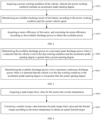
FIG. 1 is a schematic flow chart of a control method according to an embodiment of the present disclosure; -
FIG. 2 is a schematic flow chart for determining a slip working condition according to an embodiment of the present disclosure; -
FIG. 3 is a schematic flow chart for determining a target speed according to an embodiment of the present disclosure; -
FIG. 4 is a schematic flow chart for acquiring an available power according to an embodiment of the present disclosure; -
FIG. 5 is a schematic flow chart for determining an available discharge power according to an embodiment of the present disclosure; -
FIG. 6 is a schematic flow chart for comparing peak torque limit values according to an embodiment of the present disclosure; -
FIG. 7 is a schematic flow chart of temperature correction according to an embodiment of the present disclosure; -
FIG. 8 is a schematic diagram of modules of a control apparatus according to an embodiment of the present disclosure; and -
FIG. 9 is a schematic diagram of modules of an electronic device according to an embodiment of the present disclosure. - The technical solutions in the embodiments of the application will be described clearly and completely in conjunction with the accompanying drawings in the examples of the application. Obviously, the described examples are only part of the embodiments of the application, rather than all of the examples. Based on the examples in the present disclosure, all other examples obtained by a person skilled in the art without involving any inventive effort are within the scope of protection of the present disclosure.
- When the vehicle runs on a road with low friction, the tire slips easily, which affects the running safety of the vehicle and increases the probability of a safety accident. The internal VCU of the electric drive vehicle internally calculates, distributes, coordinates, and needs to convert a battery power into motor torque limits. It limits the motor torque on the torque path, and finally sends the torque request to each controller.
- In some embodiments, the strategy of the slip working condition only considers the single-wheel slip working condition. However, when the wheels on two ends of the drive wheels of the vehicle slip, the difference between the left and right wheel speeds is small, resulting in inaccuracies in the resulting limited torque.
- According to a first aspect of an embodiment of the present disclosure. Referring to
FIG. 1 , a control method of a motor torque is provided, the control method including: - S1, acquiring a current vehicle speed of a vehicle, wheel speeds at two ends of a drive shaft, and the wheel speed difference between the wheel speeds at the two ends of the drive shaft.
- When a vehicle slip occurs, two situations are generally included, one is a single-wheel slip, and the other is a double-wheel slip. When a single-wheel slip occurs, the friction between the wheel at one end of the drive shaft and the ground is relatively small, and the friction at the other end is relatively large. Due to a differential, the wheel at a section with a relatively small friction runs idle, while the wheel at a side with an increased friction has a relatively slow rotation speed.
- The other is that the friction between the wheels at two ends of the drive shaft and the ground is small, resulting in that the rotation speeds of the two wheels are both fast, while the difference between the wheel speeds is small, resulting in that the vehicle speed is less than the wheel speed, then the double-wheel slip occurs. However, when the vehicle is traveling normally, the vehicle speed is close to the wheel speeds at the two ends of the drive shaft. Therefore, the conditions where the double-wheel slip occurs and the vehicle runs normally are considered to be non-single-wheel slip working conditions in a unified manner. Thus, the current vehicle speed of the vehicle and the wheel speeds at the two ends of the drive shaft are obtained in real time during the travel of the vehicle, for determining the current working condition of the vehicle.
- In the acquisition, the wheel speeds at two ends may be a rotation speed value or a speed value. When the acquired wheel speed is the rotation speed, the wheel speed value is converted into a vehicle speed value, so as to facilitate calculation and comparison.
- S2, determining a current working condition corresponding to the vehicle based on the wheel speed difference, the wheel speeds, and the current vehicle speed, wherein the current working condition includes a single-wheel slip working condition and a non-single-wheel slip working condition.
- The current vehicle speed of the vehicle and the wheel speeds at the two ends of the drive shaft are acquired in real time during the travel of the vehicle, and it is decided whether the vehicle enters a single-wheel slip state according to the wheel speed difference of the wheel speeds at the two ends of the drive shaft. When the wheel speed difference is large, the vehicle may be considered to enter the single-wheel slip working condition. When the wheel speed difference is small, the vehicle may be considered to be in a normal travel state or that double wheels at the drive shaft slip simultaneously.
- S3, determining a target speed on which a torque limiting operation to be performed is based, based on the slip working condition, the current vehicle speed, and the wheel speeds at the two ends of the drive shaft.
- In order to effectively improve the torque-limiting action of the motor, and to reduce the damage to the battery, since the vehicle speed is generally 0 in the case of single-wheel slip, and the wheel speed of the wheels at the drive shaft is faster in the case of double-wheel slip, it is often necessary to depend on the speed closer to the actual wheel speed when acquiring the data, so that the obtained limited torque is more accurate. Therefore, different target speeds are selected under different slip working conditions.
- S4, determining a limited torque of a motor according to the target speed and an available power of a battery.
- According to the model of the vehicle itself, the output limited torques tend to be different based on the different powers of the battery. Therefore, according to the available power of the battery and the acquired target speed, the output limited torque to disengage the vehicle from the slip state can be calculated, for example, according to the following formula in a particular embodiment:

where T is the limited torque, P is the available power, and n is the target speed, wherein in a specific embodiment, when n is a speed value or a motor speed value, it is converted into a wheel speed value of a wheel at the drive shaft, thereby acquiring accurate data. - S5, controlling the motor to output a torque according to the limited torque.
- After the limited torque is obtained, the motor torque is limited on the VCU internal torque path and the torque request is sent to each controller.
- When the current vehicle speed of the vehicle and the wheel speeds at the two ends of the drive shaft are acquired in real time, the wheel speed difference of the drive shaft is determined according to the wheel speeds at the two ends in real time, and it is decided whether the vehicle is slipping according to the vehicle speed, the wheel speed and the wheel speed difference. When the vehicle has a single-wheel slip, one end of the wheels at the two ends of the drive shaft is idle due to the slip, and the other end has a slower rotation speed, while the vehicle speed is less than or equal to the wheel speed of the wheel with the slower rotation speed. Therefore, the motor speed may be taken as a target speed on which the torque limiting operation to be performed is based; while when the vehicle has a double-wheel slip at the drive shaft, it can be considered that both the wheels at the two ends of the drive wheel are idle, and the vehicle speed is slow. Therefore, the greater speed value among the wheel speeds at the two ends of the drive shaft and the current vehicle speed are taken as the target speeds for determining the torque limiting operation to be performed. When the vehicle is traveling normally, the values of the wheel speeds at two ends of the drive shaft and the current vehicle speed are consistent, so that the double-wheel slip working condition and the normal travel condition may be combined as the non-single-wheel slip working condition, thereby effectively improving the accuracy of the determined limited torque, and further improving the torque limiting effect on the motor.
- In some embodiments, referring to
FIG. 2 , the determining the current working condition corresponding to the vehicle based on the wheel speed difference, the wheel speeds, and the current vehicle speed includes: - S101, determining that the vehicle is in the single-wheel slip working condition when it is detected that the wheel speed difference exceeds a preset wheel speed difference.
- Due to the differential, when the single-wheel slip occurs, the wheel at one side where the frictional force is smaller idles, and the wheel at the other side where the frictional force is greater rotates at a slower speed. Thus, it can be considered that the single-wheel slip occurs at the side of the drive shaft of the vehicle when it is detected that the wheel speed difference exceeds the preset wheel speed difference.
- The preset wheel speed difference may be calibrated according to different vehicle models and performances so as to improve applicability.
- S102, determining that the vehicle is in the non-single-wheel slip working condition when it is detected that the wheel speed difference does not exceed the preset wheel speed difference and the wheel speeds at the two ends of the drive shaft are not less than the vehicle speed.
- When it is detected that the wheel speed difference does not exceed the preset wheel speed difference and the wheel speeds at two ends of the drive shaft are both greater than the vehicle speed, it cannot be determined whether the vehicle slips depending on the wheel speed difference at this moment. Therefore, when the wheel speed difference is detected at two ends, the difference between the vehicle speed and the wheel speeds at the two ends of the drive shaft is detected. When the difference is greater than the preset difference, it is determined that the double-wheel slip occurs. When the difference is less than or equal to the preset difference, it is determined that the vehicle is in a normal travel, and both the double-wheel slip and the normal travel are non-single-wheel slip working conditions.
- In a specific embodiment, when the wheel speeds at the two ends of the drive shaft are different, the difference between the current vehicle speed and the lower wheel speed is used as a criterion to improve accuracy.
- In some embodiments, referring to
FIG. 3 , the determining the target speed on which the torque limiting operation to be performed is based, based on the current working condition, the wheel speed difference, and the wheel speeds at the two ends of the drive shaft includes: - S201, determining the motor speed as the target speed when it is detected that the vehicle is in the single-wheel slip working condition.
- When the single-wheel slip occurs, one end of the wheels at two ends of the drive shaft idles due to the slip, and the rotation speed of the other end and the vehicle speed are generally close to 0. Thus, the motor speed is directly obtained as a reference value, thereby making the limited torque more accurate.
- S202, determining a greater speed value among the wheel speeds at the two ends of the drive shaft and the current vehicle speed as the target speed when it is detected that the vehicle is in the non-single-wheel slip working condition.
- In this case, since the vehicle speed is low, if the limited torque is calculated according to the vehicle speed, the limited torque is easy to be large, and the torque limiting effect on the motor is poor. When the vehicle is traveling normally, the wheel speeds at the two ends of the drive shaft and the current vehicle speed are substantially equal, so that the greater value thereof is used as the target speed, thereby satisfying the torque limiting operation at the time of double-wheel slip of the vehicle and at the time of traveling normally, improving the applicability of the method.
- In another embodiment, when the vehicle speed signal or the drive wheel speed signal is detected to be invalid or abnormal, the motor speed is determined as the target speed, effectively avoiding the fluctuation of the limited torque of the motor when the signal is abnormal, improving the stability of the system.
- In some embodiments, referring to
FIG. 4 , the available power is obtained by: - S301, acquiring a power working condition of the vehicle, wherein the power working condition includes an accelerator pedal opening degree.
- The battery discharge power includes a maximum continuous discharge power and a maximum peak discharge power. Here, the maximum continuous discharge power is a normal discharge power when the battery is continuously working. The maximum peak discharge power is the maximum power of the battery, but the maximum peak discharge power may only be output for a short time. Therefore, in order to maximize the use of the battery, different powers may be selected according to different operating conditions of the current vehicle.
- S302, determining an available discharge power of the battery based on the power working condition and the current vehicle speed.
- Here, the driving demand of the driver is decided according to the current vehicle speed and the power working condition so as to determine the output power of the battery. When the power working condition and the current vehicle speed indicate that the driver needs high power, the battery is controlled to output the maximum peak discharge power in a short time, otherwise, the normal maximum continuous discharge power is output.
- S303, acquiring a motor efficiency of the motor, and correcting the available discharge power according to the motor efficiency to obtain the available power.
- When the battery supplies power to the motor, the power output by the battery to the motor cannot be fully converted into the output torque of the motor. Therefore, after determining the available discharge power of the motor, the available discharge power is corrected by the motor efficiency of the motor itself, i.e., the efficiency of converting the battery power into the output torque, so as to obtain the accurate available power, thereby making the final determined limited torque more accurate.
- In some embodiments, the control method further includes the following steps:
acquiring a consumed power of other high-voltage components of the vehicle, and a start-up reserved power when an engine is in a stopped state, and correcting the available power according to the consumed power and the start-up reserved power. - Specifically, the sum of the power demand of each component under the current working condition of the vehicle is obtained as the consumed power, and the power required when the engine is started, which is calibrated in advance, is detected as the reserved power for starting. In the present embodiment, the reserved power for starting may be 2 kw, and the consumed power and the reserved power for starting are subtracted from the available discharge power, so that the vehicle may ensure the normal operation of other components and the engine can be started in time when the engine needs to be started, which improves the practicability of the present method.
- In some embodiments, referring to
FIG. 5 , the determining the available discharge power of the battery according to the power working condition and the current vehicle speed includes the following steps: - S401, determining the available discharge power as a maximum peak discharge power when it is detected that the vehicle is not in the slip working condition and the accelerator pedal opening degree is greater than a preset opening degree.
- When the accelerator pedal opening degree is not less than the preset opening degree, it can be considered that the vehicle has an acceleration intention. Therefore, a large power is provided to improve the acceleration performance of the vehicle.
- S402, determining the available discharge power to be a maximum continuous discharge power when it is detected that the vehicle is in the slip working condition or the accelerator pedal opening degree is not greater than the preset opening degree
- When it is detected that the vehicle is in the slip working condition, if the maximum peak discharge power is selected, over-discharge of the battery is likely to occur. Also, there is no power shortage at this time, but the tire adhesion is poor. Thus, the battery is controlled to output a relatively low maximum continuous discharge power.
- When the accelerator pedal opening degree is less than the preset opening degree, it may be considered that the vehicle is in a constant-speed travel state or the acceleration intention is low. Therefore, the battery is controlled to output a relatively low maximum continuous discharge power.
- Since the maximum peak discharge power has certain damage to the battery, the maximum peak discharge power is output within a preset time period. For example, the preset time period may be 6 seconds. When the maximum peak discharge power is output for more than 6 seconds, it is switched to be the maximum continuous discharge power to improve the service life of the battery.
- Here, the preset opening degree may be determined with respect to the current vehicle speed. When the current vehicle speed is low, the preset opening degree may be a small opening degree. For example, when the vehicle speed is 10 km/h, the preset opening degree may be 20%. When the current vehicle speed is high, the preset opening degree is set to be a small opening degree, so as to decide the driving intention of the vehicle more accurately and further improve the utilization rate of battery power.
- In some embodiments, referring to
FIG. 6 , the method further includes: - S501, acquiring a peak torque limit value of the motor and a motor temperature.
- When the calculated limited torque exceeds the maximum output torque of the motor, i.e., the peak torque limit value, the motor cannot output this torque, which may easily lead to motor failure, so that the peak torque limit value of the motor is acquired to determine whether the calculated limiting torque can be output.
- At the same time, since the temperature of the motor has an influence on the working condition of the motor, according to the temperature difference of the motor, the torque of the motor is corrected by acquiring the temperature of the motor, so as to improve the accuracy of the final output torque of the motor.
- S502, correcting a smaller torque value between the peak torque limit value and the limited torque according to the motor temperature to obtain an actual limited torque.
- By comparing with the peak torque limit value, the peak torque limit value is output when the calculated limited torque exceeds the maximum output torque of the motor, i.e., the peak torque limit value, so as to effectively avoid the occurrence of motor fault fluctuation. At the same time, the accuracy of the final output torque of the motor is effectively improved by correcting the final output torque of the motor.
- The controlling the motor to output the torque according to the limited torque includes the following step:
controlling the motor to output the torque according to the actual limited torque. - In some embodiments, referring to
FIG. 7 , the correcting a smaller torque value between the peak torque limit value and the limited torque according to the motor temperature to obtain the actual limited torque includes: - S601, acquiring a temperature correction coefficient graph.
- According to the bench test previously tested, the influence of different motor temperatures on the motor torque and the influence on itself when the motor at different temperatures output different torque are determined to obtain the temperature correction coefficient graph which characterizes the temperature correction coefficient of the motor output torque corresponding to the motor temperature.
- S602, determining a temperature correction coefficient according to the motor temperature and the temperature correction coefficient graph.
- According to the motor temperature, the influence degree of the current motor temperature on the torque, namely, the temperature correction coefficient, can be obtained by table looking-up.
- S603, correcting a smaller torque value between the peak torque limit value and the limited torque according to the temperature correction coefficient to obtain the actual limited torque value.
- The actual limited torque of the final motor output may be obtained by multiplying the temperature correction coefficient by the smaller torque value between the peak torque limit value and the limited torque.
- A second aspect of an embodiment of the present disclosure provides a control apparatus of a motor torque. Referring to
FIG. 8 , thecontrol apparatus 7 includes: - an
acquisition module 71 configured for acquiring a current vehicle speed of a vehicle, wheel speeds at two ends of a drive shaft, and a wheel speed difference between the wheel speeds at the two ends of the drive shaft; - a decision module 72 configured for determining a current working condition corresponding to the vehicle based on the wheel speed difference, the wheel speeds, and the current vehicle speed, wherein the current working condition includes a single-wheel slip working condition and a non-single-wheel slip working condition;
- a
determination module 73 configured for determining a target speed on which a torque limiting operation to be performed is based, based on the current working condition, the current vehicle speed, and the wheel speeds at the two ends of the drive shaft; - a calculation module 74 configured for determining a limited torque of the motor according to the target speed and an available power of a battery; and
- an
execution module 75 configured for controlling the motor to output a torque according to the limited torque. - In some embodiments, the decision module 72 is further configured for performing the following steps:
- determining that the vehicle is in the single-wheel slip working condition when it is detected that the wheel speed difference exceeds the preset wheel speed difference; and
- determining that the vehicle is in the non-single-wheel slip working condition when it is detected that the wheel speed difference does not exceed the preset wheel speed difference and the wheel speeds at the two ends of the drive shaft are not less than the vehicle speed.
- In some embodiments, the
determination module 73 is further configured for performing the following steps: - determining the motor speed as the target speed when it is detected that the vehicle is in the single-wheel slip working condition; and
- determining a greater speed value among the wheel speeds at the two ends of the drive shaft and the current vehicle speed as the target speed when it is detected that the vehicle is in the non-single-wheel slip working condition.
- In some embodiments, the
determination module 73 is further configured for performing the following steps: - acquiring a power working condition of the vehicle, wherein the power working condition includes an accelerator pedal opening degree;
- determining an available discharge power of the battery according to the power working condition and the current vehicle speed; and
- acquiring a motor efficiency of the motor, and correcting the motor efficiency according to the available discharge power to obtain the available power.
- In some embodiments, the
determination module 73 is further configured for performing the following steps: - determining the available discharge power as a maximum peak discharge power when it is detected that the vehicle is not in the slip working condition and the accelerator pedal opening degree is greater than a preset opening degree; and
- determining the available discharge power to be a maximum continuous discharge power when it is detected that the vehicle is in the slip working condition or the accelerator pedal opening degree is not greater than the preset opening degree.
- In some embodiments, the
control device 7 further includes a correction module for performing the following steps: - acquiring a peak torque limit value for the motor and the motor temperature; and
- correcting a smaller torque value of the peak torque limit value and the limited torque according to the motor temperature to obtain an actual limited torque.
- In some embodiments, the correction module is further configured for performing the following steps:
- acquiring a temperature correction coefficient graph;
- determining a temperature correction coefficient according to the motor temperature and the temperature correction coefficient graph; and
- correcting a smaller torque value of the peak torque limit value and the limited torque according to the temperature correction coefficient to obtain the actual limited torque value.
- An electronic device according to a third aspect of an embodiment of the present disclosure, with reference to
FIG. 9 , includes: - a memory configured for storing a computer program; and
- a processor configured for executing a computer program stored on the memory to implement any one of the control methods.
- A vehicle according to a fourth aspect of an embodiment of the present disclosure, includes the above-described electronic device to implement the above-described control method.
- A fifth aspect of an embodiment of the present disclosure provides a computer program product including computer readable codes which, when run on an electronic device, cause the electronic device to perform any one of the control methods.
- A sixth aspect of an embodiment of the present disclosure provides a computer-readable medium, in which a computer program is stored which, when runs on an electronic device, causes the electronic device to perform any one of the control methods.
- With respect to the apparatus embodiment, which is substantially similar to the method embodiment, the description is relatively simple, for which reference is made to the partial description of the method embodiment.
- Each embodiment described in this description will focus on the differences from the other embodiments, and reference will be made to the same or similar parts in each embodiment.
- Persons skilled in the art will appreciate that embodiments of the present disclosure may be provided as a method, an apparatus, or a computer program product. Accordingly, embodiments of the present disclosure may take the form of an entire hardware embodiment, an entire software embodiment, or an embodiment combining software and hardware aspects. Moreover, the embodiments of the present disclosure may take the form of a computer program product embodied on one or more computer-usable storage media (including, but not limited to, magnetic disk storage, CD-ROM, optical storage, and the like) having computer-usable program code embodied therein.
- Embodiments of the present disclosure are described with reference to flowchart illustrations and/or block diagrams of methods, terminal devices (systems), and computer program products according to embodiments of the present disclosure. It will be understood that each flow and/ or block of the flowcharts and/or block diagrams in combination with flows and/or blocks in the flowcharts and/or block diagrams can be implemented by computer program instructions. These computer program instructions may be provided to processors of a general purpose computer, a special purpose computer, an embedded processor, or other programmable data processing terminal equipment to produce a machine, such that the instructions, which are executed via the processor of the computer or other programmable data processing terminal equipment, create means for implementing the functions specified in the flowchart flow or flows and/or block diagram block or blocks.
- These computer program instructions may also be stored in a computer-readable memory that can direct a computer or other programmable data processing terminal devices to function in a particular manner, such that the instructions stored in the computer-readable memory produce an article of manufacture including instruction means which implement the function specified in the flowchart flow or flows and/or block diagram block or blocks.
- These computer program instructions may also be loaded onto a computer or other programmable data processing terminal devices to cause a series of operational steps to be performed on the computer or other programmable devices to produce a computer implemented process, such that the instructions executed on the computer or other programmable terminal devices provide steps for implementing the functions specified in the flowchart flow or flows and/or block diagram block or blocks.
- While preferred embodiments of the embodiments of the present disclosure have been described, additional variations and modifications to these embodiments will occur to those skilled in the art once the basic inventive concept is known. Therefore, it is intended that the appended claims be interpreted as including the preferred embodiments and all alterations and modifications that fall within the scope of the embodiments of the present disclosure.
- Finally, it should be noted that relational terms such as first and second, and the like, may be used herein to distinguish one entity or action from another entity or action without necessarily requiring or implying any such actual relationship or order between such entities or actions. Furthermore, the terms "comprises", "comprising", or any other variation thereof, are intended to cover a non-exclusive inclusion, such that a process, method, article, or terminal device that includes a list of elements does not include only those elements but may include other elements not expressly listed or inherent to such process, method, article, or terminal device. An element proceeded by the phrase "including a" does not, without more constraints, preclude the existence of additional identical elements in the process, method, article, or terminal device that includes the element.
- The control method and apparatus of a motor torque, the electronic device, and the vehicle provided by the present disclosure have been described in detail, and the principles and embodiments of the present disclosure have been described herein using specific examples. The above description of the embodiments is only for helping to understand the method and the core idea of the present disclosure. Meanwhile, for a person skilled in the art, according to the idea of the present disclosure, there would be changes in the specific implementation and the application scope. In summary, the contents of the present description should not be construed as limiting the present disclosure.
Claims (14)
- A control method of a motor torque, characterized in that the control method comprises:acquiring a current vehicle speed of a vehicle, wheel speeds at two ends of a drive shaft, and a wheel speed difference between the wheel speeds at the two ends of the drive shaft;determining a current working condition corresponding to the vehicle based on the wheel speed difference, the wheel speeds, and the current vehicle speed, wherein the current working condition comprises a single-wheel slip working condition and a non-single-wheel slip working condition;determining a target speed on which a torque limiting operation to be performed is based, based on the current working condition, the current vehicle speed, and the wheel speeds at the two ends of the drive shaft;determining a limited torque of a motor according to the target speed and an available power of a battery; andcontrolling the motor to output a torque according to the limited torque.
- The control method according to claim 1, characterized in that the determining the current working condition corresponding to the vehicle based on the wheel speed difference, the wheel speeds, and the current vehicle speed comprises:determining that the vehicle is in the single-wheel slip working condition when it is detected that the wheel speed difference exceeds a preset wheel speed difference; anddetermining that the vehicle is in the non-single-wheel slip working condition when it is detected that the wheel speed difference does not exceed the preset wheel speed difference.
- The control method according to claim 1, characterized in that the determining the target speed on which the torque limiting operation to be performed is based, based on the current working condition, the wheel speed difference, and the wheel speeds at the two ends of the drive shaft, comprises:determining a motor speed as the target speed when it is detected that the vehicle is in the single-wheel slip working condition; anddetermining a greater speed value among the wheel speeds at two ends of the drive shaft and the current vehicle speed as the target speed when it is detected that the vehicle is in the non-single-wheel slip working condition.
- The control method according to claim 1, characterized in that the available power is obtained by steps of:acquiring a power working condition of the vehicle, wherein the power working condition comprises an accelerator pedal opening degree;determining an available discharge power of the battery according to the power working condition and the current vehicle speed; andacquiring a motor efficiency of the motor, and correcting the available discharge power according to the motor efficiency to obtain the available power.
- The control method according to claim 4, characterized in that the determining an available discharge power of the battery according to the power working condition and the current vehicle speed comprises:determining the available discharge power as a maximum peak discharge power when it is detected that the vehicle is not in the slip working condition and the accelerator pedal opening degree is greater than a preset opening degree; anddetermining the available discharge power to be a maximum continuous discharge power when it is detected that the vehicle is in the slip working condition or the accelerator pedal opening degree is not greater than the preset opening degree.
- The control method according to claim 4, characterized in that the control method further comprises:
acquiring a consumed power of each component of the vehicle, and a start-up reserved power when an engine is in a stopped state, and correcting the available power according to the consumed power and the start-up reserved power. - The control method according to claim 1, characterized in that the method further comprises:acquiring a peak torque limit value for the motor and a motor temperature; andcorrecting a smaller torque value between the peak torque limit value and the limited torque according to the motor temperature to obtain an actual limited torque;wherein the controlling the motor to output the torque according to the limited torque comprises:
controlling the motor to output the torque according to the actual limited torque. - The control method according to claim 7, characterized in that the correcting the smaller torque value between the peak torque limit value and the limited torque according to the motor temperature to obtain the actual limited torque comprises:acquiring a temperature correction coefficient graph;determining a temperature correction coefficient according to the motor temperature and the temperature correction coefficient graph; andcorrecting a smaller torque value between the peak torque limit value and the limited torque according to the temperature correction coefficient to obtain the actual limited torque.
- A control apparatus of a motor torque, characterized in that the control apparatus comprises:an acquisition module configured for acquiring a current vehicle speed of a vehicle, wheel speeds at two ends of a drive shaft, and a wheel speed difference between the wheel speeds at the two ends of the drive shaft;a decision module configured for determining a current working condition corresponding to the vehicle based on the wheel speed difference, the wheel speeds, and the current vehicle speed, wherein the current working condition comprises a single-wheel slip working condition and a non-single-wheel slip working condition;a determination module configured for determining a target speed on which the torque limiting operation to be performed is based, based on the current working condition, the wheel speed difference, and the wheel speeds at the two ends of the drive shaft;a calculation module configured for determining a limited torque of a motor according to the target speed and an available power of a battery; andan execution module configured for controlling the motor to output a torque according to the limited torque.
- The control apparatus of the motor torque according to claim 9, characterized in that the control apparatus further comprises a correction module configured for performing steps of:acquiring a peak torque limit value for the motor and a motor temperature; andcorrecting a smaller torque value between the peak torque limit value and the limited torque according to the motor temperature to obtain an actual limited torque.
- An electronic device, characterized by comprising:a memory configured for storing a computer program; anda processor configured for executing a computer program stored on the memory to implement the control method according to any one of claims 1-8.
- A vehicle, characterized by comprising the electronic device according to claim 11.
- A computer program product comprising computer-readable codes which, when run on an electronic device, causes the electronic device to perform the control method according to any one of claims 1-8.
- A computer-readable medium, in which a computer program is stored which, when runs on an electronic device, causes the electronic device to perform the control method according to any one of claims 1-8.
Applications Claiming Priority (2)
| Application Number | Priority Date | Filing Date | Title |
|---|---|---|---|
| CN202210130489.9A CN115246324B (en) | 2022-02-11 | 2022-02-11 | Motor torque control method, device, electronic equipment and vehicle |
| PCT/CN2023/072574 WO2023151458A1 (en) | 2022-02-11 | 2023-01-17 | Motor torque control method and apparatus, electronic device, and vehicle |
Publications (2)
| Publication Number | Publication Date |
|---|---|
| EP4464537A1 true EP4464537A1 (en) | 2024-11-20 |
| EP4464537A4 EP4464537A4 (en) | 2025-06-04 |
Family
ID=83698385
Family Applications (1)
| Application Number | Title | Priority Date | Filing Date |
|---|---|---|---|
| EP23752238.8A Pending EP4464537A4 (en) | 2022-02-11 | 2023-01-17 | MOTOR TORQUE CONTROL METHOD AND APPARATUS, ELECTRONIC DEVICE AND VEHICLE |
Country Status (3)
| Country | Link |
|---|---|
| EP (1) | EP4464537A4 (en) |
| CN (1) | CN115246324B (en) |
| WO (1) | WO2023151458A1 (en) |
Cited By (1)
| Publication number | Priority date | Publication date | Assignee | Title |
|---|---|---|---|---|
| US12420645B1 (en) * | 2022-02-02 | 2025-09-23 | Motiv Power Systems, Inc. | Methods and apparatus for performing hill hold with reduced oscillations in vehicle position |
Families Citing this family (11)
| Publication number | Priority date | Publication date | Assignee | Title |
|---|---|---|---|---|
| CN115246324B (en) * | 2022-02-11 | 2025-01-28 | 长城汽车股份有限公司 | Motor torque control method, device, electronic equipment and vehicle |
| CN115402120B (en) * | 2022-10-31 | 2023-02-10 | 北京京深深向科技有限公司 | Torque Error Correction Method and Device for Drive System of Distributed Drive Vehicle |
| CN116252633B (en) * | 2022-12-06 | 2026-01-27 | 深蓝汽车科技有限公司 | Differential quota method, device and equipment based on motor and storage medium |
| CN120152872B (en) * | 2023-03-31 | 2026-02-06 | 深圳引望智能技术有限公司 | Vehicle control methods, devices, vehicles and storage media |
| CN116946108A (en) * | 2023-05-29 | 2023-10-27 | 中国重汽集团济南动力有限公司 | Mixed control system and method for commercial vehicle |
| CN116691364B (en) * | 2023-05-30 | 2025-10-24 | 深蓝汽车科技有限公司 | Vehicle wheel speed control method, device, electronic device and storage medium |
| CN116714447A (en) * | 2023-07-21 | 2023-09-08 | 长城汽车股份有限公司 | A vehicle torque control method and device and a hybrid vehicle |
| CN117141245B (en) * | 2023-08-30 | 2026-05-08 | 重庆长安汽车股份有限公司 | Automatic vehicle traction control methods, electronic devices and storage media |
| CN117922530A (en) * | 2024-01-30 | 2024-04-26 | 重庆长安汽车股份有限公司 | Torque control method and device for hybrid vehicle, vehicle and storage medium |
| CN117685361B (en) * | 2024-02-04 | 2024-06-18 | 潍柴动力股份有限公司 | Gear shifting control method and device of AMT gear box system, vehicle and storage medium |
| CN118636698B (en) * | 2024-07-11 | 2025-10-31 | 奇瑞汽车股份有限公司 | Differential protection method, differential protection device, vehicle, medium, and program |
Family Cites Families (17)
| Publication number | Priority date | Publication date | Assignee | Title |
|---|---|---|---|---|
| CA1123496A (en) * | 1978-07-20 | 1982-05-11 | James S. Mark | Locomotive wheel slip determination |
| JP2008199716A (en) * | 2007-02-09 | 2008-08-28 | Hitachi Ltd | VEHICLE DRIVE DEVICE AND ELECTRONIC CIRCUIT DEVICE USED FOR THE SAME |
| CN105015549B (en) * | 2014-04-21 | 2017-08-29 | 上海汽车集团股份有限公司 | The torque control method and device of power drive system |
| KR101786666B1 (en) * | 2015-08-26 | 2017-10-18 | 현대자동차 주식회사 | Apparatus and method for controlling of vehicle having motor |
| CN106183892B (en) * | 2016-10-09 | 2018-08-10 | 重庆理工大学 | The experimental model and driving stability control method of electric wheel drive vehicle |
| CN108248449B (en) * | 2016-12-29 | 2020-11-06 | 比亚迪股份有限公司 | Driving anti-skid control method and device for four-wheel drive electric vehicle |
| CN107139916B (en) * | 2017-05-17 | 2019-09-24 | 中国第一汽车股份有限公司 | Operator torque demands' analytic method for hybrid vehicle |
| JP7200473B2 (en) * | 2017-08-10 | 2023-01-10 | 株式会社デンソー | motor controller |
| CN107458269B (en) * | 2017-08-21 | 2019-10-29 | 奇瑞新能源汽车技术有限公司 | A kind of pure electric automobile stabilitrak and method |
| US11584352B2 (en) * | 2018-10-09 | 2023-02-21 | Ford Global Technologies, Llc | Estimation of vehicle speed in all-wheel-drive vehicle |
| US11161514B2 (en) * | 2019-09-12 | 2021-11-02 | Ford Global Technologies, Llc | System and method for coordinating independent axles for continuous wheel slip control |
| CN111086500B (en) * | 2020-03-23 | 2020-07-31 | 盛瑞传动股份有限公司 | Vehicle slip protection method and system and vehicle |
| CN112477622B (en) * | 2020-11-12 | 2022-08-16 | 东风汽车集团有限公司 | Vehicle control method and device, vehicle and medium |
| CN112693328B (en) * | 2021-01-07 | 2022-06-24 | 北京汽车集团越野车有限公司 | Four-wheel non-steering mechanism distributed drive automobile anti-skid control method and device |
| CN112874320B (en) * | 2021-02-22 | 2023-01-24 | 北京车和家信息技术有限公司 | Differential active protection control method, device, equipment and storage medium |
| CN113895235B (en) * | 2021-11-15 | 2023-08-15 | 奇瑞新能源汽车股份有限公司 | Control method and device for four-wheel drive vehicle, new energy automobile and storage medium |
| CN115246324B (en) * | 2022-02-11 | 2025-01-28 | 长城汽车股份有限公司 | Motor torque control method, device, electronic equipment and vehicle |
-
2022
- 2022-02-11 CN CN202210130489.9A patent/CN115246324B/en active Active
-
2023
- 2023-01-17 EP EP23752238.8A patent/EP4464537A4/en active Pending
- 2023-01-17 WO PCT/CN2023/072574 patent/WO2023151458A1/en not_active Ceased
Cited By (1)
| Publication number | Priority date | Publication date | Assignee | Title |
|---|---|---|---|---|
| US12420645B1 (en) * | 2022-02-02 | 2025-09-23 | Motiv Power Systems, Inc. | Methods and apparatus for performing hill hold with reduced oscillations in vehicle position |
Also Published As
| Publication number | Publication date |
|---|---|
| CN115246324A (en) | 2022-10-28 |
| EP4464537A4 (en) | 2025-06-04 |
| CN115246324B (en) | 2025-01-28 |
| WO2023151458A1 (en) | 2023-08-17 |
Similar Documents
| Publication | Publication Date | Title |
|---|---|---|
| CN115246324B (en) | Motor torque control method, device, electronic equipment and vehicle | |
| EP2609316B1 (en) | Hybrid power train rate control | |
| EP4112409A1 (en) | Determination method for drive force to be requested for hybrid vehicle, and apparatus | |
| US9604623B2 (en) | Drive control system for electric motor and method of controlling electric motor | |
| EP3020599B1 (en) | Vehicle driven by electric motor and control method for vehicle | |
| US9776526B2 (en) | Fuel cell system, fuel cell vehicle, and method of controlling fuel cell system | |
| KR101637709B1 (en) | Braking control method for eco-friendly vehicle | |
| US9267556B2 (en) | Apparatus and method for determining engine clutch transfer torque of environmentally-friendly vehicle | |
| US9156467B2 (en) | Vehicle power generating device and power generation control method | |
| EP2700550B1 (en) | Vehicle and vehicle control method | |
| KR101765643B1 (en) | Method and device for controlling state of charge of battery for cruise control of hybrid vehicle | |
| CN115257733B (en) | Cruise control method, device and equipment | |
| JP5211573B2 (en) | Power generation control device for hybrid vehicle | |
| CN112140901B (en) | Torque control method and device | |
| CN112537206A (en) | New energy automobile torque monitoring method and system | |
| JP5578336B2 (en) | Control device for hybrid vehicle | |
| US11563330B2 (en) | Electric vehicle control device and electric vehicle | |
| JP2017118766A (en) | Vehicle motor torque estimation device | |
| CN114475269B (en) | Motor control method and device, vehicle and medium | |
| JP2019087496A (en) | Cell system | |
| JP4325610B2 (en) | Drive device for hybrid vehicle | |
| CN117774938B (en) | Automobile fault sliding control method and device, vehicle and readable storage medium | |
| CN118769923B (en) | Vehicle control method and device, vehicle and storage medium | |
| US20240391327A1 (en) | Electric power limiter | |
| CN114559927B (en) | Vehicle power reduction method, device, electronic device and readable storage medium |
Legal Events
| Date | Code | Title | Description |
|---|---|---|---|
| STAA | Information on the status of an ep patent application or granted ep patent |
Free format text: STATUS: THE INTERNATIONAL PUBLICATION HAS BEEN MADE |
|
| PUAI | Public reference made under article 153(3) epc to a published international application that has entered the european phase |
Free format text: ORIGINAL CODE: 0009012 |
|
| STAA | Information on the status of an ep patent application or granted ep patent |
Free format text: STATUS: REQUEST FOR EXAMINATION WAS MADE |
|
| 17P | Request for examination filed |
Effective date: 20240816 |
|
| AK | Designated contracting states |
Kind code of ref document: A1 Designated state(s): AL AT BE BG CH CY CZ DE DK EE ES FI FR GB GR HR HU IE IS IT LI LT LU LV MC ME MK MT NL NO PL PT RO RS SE SI SK SM TR |
|
| DAV | Request for validation of the european patent (deleted) | ||
| DAX | Request for extension of the european patent (deleted) | ||
| A4 | Supplementary search report drawn up and despatched |
Effective date: 20250507 |
|
| RIC1 | Information provided on ipc code assigned before grant |
Ipc: B60L 3/12 20060101ALI20250429BHEP Ipc: B60L 3/10 20060101ALI20250429BHEP Ipc: B60L 15/20 20060101AFI20250429BHEP |