EP4464526A1 - Bonding jig and bonding method - Google Patents
Bonding jig and bonding method Download PDFInfo
- Publication number
- EP4464526A1 EP4464526A1 EP22920674.3A EP22920674A EP4464526A1 EP 4464526 A1 EP4464526 A1 EP 4464526A1 EP 22920674 A EP22920674 A EP 22920674A EP 4464526 A1 EP4464526 A1 EP 4464526A1
- Authority
- EP
- European Patent Office
- Prior art keywords
- bonding
- wall
- wall portions
- state
- wall portion
- Prior art date
- Legal status (The legal status is an assumption and is not a legal conclusion. Google has not performed a legal analysis and makes no representation as to the accuracy of the status listed.)
- Pending
Links
- 238000000034 method Methods 0.000 title claims description 26
- 230000007246 mechanism Effects 0.000 claims abstract description 78
- 238000002788 crimping Methods 0.000 claims abstract description 51
- 238000013016 damping Methods 0.000 claims abstract description 14
- 230000008569 process Effects 0.000 claims description 19
- 230000009471 action Effects 0.000 claims description 18
- 210000000078 claw Anatomy 0.000 claims description 18
- 238000007664 blowing Methods 0.000 claims description 4
- 230000001154 acute effect Effects 0.000 claims description 3
- 238000005452 bending Methods 0.000 claims description 3
- 239000000696 magnetic material Substances 0.000 claims description 3
- 239000003381 stabilizer Substances 0.000 description 28
- 230000009467 reduction Effects 0.000 description 17
- 239000000470 constituent Substances 0.000 description 14
- 238000010438 heat treatment Methods 0.000 description 14
- 239000000853 adhesive Substances 0.000 description 9
- 230000001070 adhesive effect Effects 0.000 description 9
- 230000008859 change Effects 0.000 description 6
- 230000005484 gravity Effects 0.000 description 6
- 238000010586 diagram Methods 0.000 description 4
- 239000000725 suspension Substances 0.000 description 4
- 230000000694 effects Effects 0.000 description 2
- 239000013013 elastic material Substances 0.000 description 2
- 239000000463 material Substances 0.000 description 2
- 239000011347 resin Substances 0.000 description 2
- 229920005989 resin Polymers 0.000 description 2
- 238000004804 winding Methods 0.000 description 2
- 229920000049 Carbon (fiber) Polymers 0.000 description 1
- 230000005540 biological transmission Effects 0.000 description 1
- 239000004917 carbon fiber Substances 0.000 description 1
- 238000007906 compression Methods 0.000 description 1
- 238000001035 drying Methods 0.000 description 1
- 239000000835 fiber Substances 0.000 description 1
- 239000012212 insulator Substances 0.000 description 1
- 239000002184 metal Substances 0.000 description 1
- 238000009832 plasma treatment Methods 0.000 description 1
- 238000003825 pressing Methods 0.000 description 1
- 230000004044 response Effects 0.000 description 1
- 230000000630 rising effect Effects 0.000 description 1
- 239000007787 solid Substances 0.000 description 1
- 238000004381 surface treatment Methods 0.000 description 1
- 238000004073 vulcanization Methods 0.000 description 1
- 238000003466 welding Methods 0.000 description 1
Images








Classifications
-
- B—PERFORMING OPERATIONS; TRANSPORTING
- B29—WORKING OF PLASTICS; WORKING OF SUBSTANCES IN A PLASTIC STATE IN GENERAL
- B29C—SHAPING OR JOINING OF PLASTICS; SHAPING OF MATERIAL IN A PLASTIC STATE, NOT OTHERWISE PROVIDED FOR; AFTER-TREATMENT OF THE SHAPED PRODUCTS, e.g. REPAIRING
- B29C66/00—General aspects of processes or apparatus for joining preformed parts
- B29C66/80—General aspects of machine operations or constructions and parts thereof
- B29C66/82—Pressure application arrangements, e.g. transmission or actuating mechanisms for joining tools or clamps
- B29C66/824—Actuating mechanisms
-
- B—PERFORMING OPERATIONS; TRANSPORTING
- B60—VEHICLES IN GENERAL
- B60G—VEHICLE SUSPENSION ARRANGEMENTS
- B60G21/00—Interconnection systems for two or more resiliently-suspended wheels, e.g. for stabilising a vehicle body with respect to acceleration, deceleration or centrifugal forces
- B60G21/02—Interconnection systems for two or more resiliently-suspended wheels, e.g. for stabilising a vehicle body with respect to acceleration, deceleration or centrifugal forces permanently interconnected
- B60G21/04—Interconnection systems for two or more resiliently-suspended wheels, e.g. for stabilising a vehicle body with respect to acceleration, deceleration or centrifugal forces permanently interconnected mechanically
- B60G21/05—Interconnection systems for two or more resiliently-suspended wheels, e.g. for stabilising a vehicle body with respect to acceleration, deceleration or centrifugal forces permanently interconnected mechanically between wheels on the same axle but on different sides of the vehicle, i.e. the left and right wheel suspensions being interconnected
- B60G21/055—Stabiliser bars
- B60G21/0551—Mounting means therefor
-
- B—PERFORMING OPERATIONS; TRANSPORTING
- B29—WORKING OF PLASTICS; WORKING OF SUBSTANCES IN A PLASTIC STATE IN GENERAL
- B29C—SHAPING OR JOINING OF PLASTICS; SHAPING OF MATERIAL IN A PLASTIC STATE, NOT OTHERWISE PROVIDED FOR; AFTER-TREATMENT OF THE SHAPED PRODUCTS, e.g. REPAIRING
- B29C65/00—Joining or sealing of preformed parts, e.g. welding of plastics materials; Apparatus therefor
- B29C65/48—Joining or sealing of preformed parts, e.g. welding of plastics materials; Apparatus therefor using adhesives, i.e. using supplementary joining material; solvent bonding
-
- B—PERFORMING OPERATIONS; TRANSPORTING
- B29—WORKING OF PLASTICS; WORKING OF SUBSTANCES IN A PLASTIC STATE IN GENERAL
- B29C—SHAPING OR JOINING OF PLASTICS; SHAPING OF MATERIAL IN A PLASTIC STATE, NOT OTHERWISE PROVIDED FOR; AFTER-TREATMENT OF THE SHAPED PRODUCTS, e.g. REPAIRING
- B29C65/00—Joining or sealing of preformed parts, e.g. welding of plastics materials; Apparatus therefor
- B29C65/48—Joining or sealing of preformed parts, e.g. welding of plastics materials; Apparatus therefor using adhesives, i.e. using supplementary joining material; solvent bonding
- B29C65/4805—Joining or sealing of preformed parts, e.g. welding of plastics materials; Apparatus therefor using adhesives, i.e. using supplementary joining material; solvent bonding characterised by the type of adhesives
- B29C65/483—Reactive adhesives, e.g. chemically curing adhesives
- B29C65/4835—Heat curing adhesives
-
- B—PERFORMING OPERATIONS; TRANSPORTING
- B29—WORKING OF PLASTICS; WORKING OF SUBSTANCES IN A PLASTIC STATE IN GENERAL
- B29C—SHAPING OR JOINING OF PLASTICS; SHAPING OF MATERIAL IN A PLASTIC STATE, NOT OTHERWISE PROVIDED FOR; AFTER-TREATMENT OF THE SHAPED PRODUCTS, e.g. REPAIRING
- B29C65/00—Joining or sealing of preformed parts, e.g. welding of plastics materials; Apparatus therefor
- B29C65/56—Joining or sealing of preformed parts, e.g. welding of plastics materials; Apparatus therefor using mechanical means or mechanical connections, e.g. form-fits
-
- B—PERFORMING OPERATIONS; TRANSPORTING
- B29—WORKING OF PLASTICS; WORKING OF SUBSTANCES IN A PLASTIC STATE IN GENERAL
- B29C—SHAPING OR JOINING OF PLASTICS; SHAPING OF MATERIAL IN A PLASTIC STATE, NOT OTHERWISE PROVIDED FOR; AFTER-TREATMENT OF THE SHAPED PRODUCTS, e.g. REPAIRING
- B29C65/00—Joining or sealing of preformed parts, e.g. welding of plastics materials; Apparatus therefor
- B29C65/78—Means for handling the parts to be joined, e.g. for making containers or hollow articles, e.g. means for handling sheets, plates, web-like materials, tubular articles, hollow articles or elements to be joined therewith; Means for discharging the joined articles from the joining apparatus
- B29C65/7802—Positioning the parts to be joined, e.g. aligning, indexing or centring
-
- B—PERFORMING OPERATIONS; TRANSPORTING
- B29—WORKING OF PLASTICS; WORKING OF SUBSTANCES IN A PLASTIC STATE IN GENERAL
- B29C—SHAPING OR JOINING OF PLASTICS; SHAPING OF MATERIAL IN A PLASTIC STATE, NOT OTHERWISE PROVIDED FOR; AFTER-TREATMENT OF THE SHAPED PRODUCTS, e.g. REPAIRING
- B29C66/00—General aspects of processes or apparatus for joining preformed parts
- B29C66/01—General aspects dealing with the joint area or with the area to be joined
- B29C66/05—Particular design of joint configurations
- B29C66/10—Particular design of joint configurations particular design of the joint cross-sections
- B29C66/11—Joint cross-sections comprising a single joint-segment, i.e. one of the parts to be joined comprising a single joint-segment in the joint cross-section
- B29C66/112—Single lapped joints
- B29C66/1122—Single lap to lap joints, i.e. overlap joints
-
- B—PERFORMING OPERATIONS; TRANSPORTING
- B29—WORKING OF PLASTICS; WORKING OF SUBSTANCES IN A PLASTIC STATE IN GENERAL
- B29C—SHAPING OR JOINING OF PLASTICS; SHAPING OF MATERIAL IN A PLASTIC STATE, NOT OTHERWISE PROVIDED FOR; AFTER-TREATMENT OF THE SHAPED PRODUCTS, e.g. REPAIRING
- B29C66/00—General aspects of processes or apparatus for joining preformed parts
- B29C66/01—General aspects dealing with the joint area or with the area to be joined
- B29C66/05—Particular design of joint configurations
- B29C66/10—Particular design of joint configurations particular design of the joint cross-sections
- B29C66/11—Joint cross-sections comprising a single joint-segment, i.e. one of the parts to be joined comprising a single joint-segment in the joint cross-section
- B29C66/114—Single butt joints
- B29C66/1142—Single butt to butt joints
-
- B—PERFORMING OPERATIONS; TRANSPORTING
- B29—WORKING OF PLASTICS; WORKING OF SUBSTANCES IN A PLASTIC STATE IN GENERAL
- B29C—SHAPING OR JOINING OF PLASTICS; SHAPING OF MATERIAL IN A PLASTIC STATE, NOT OTHERWISE PROVIDED FOR; AFTER-TREATMENT OF THE SHAPED PRODUCTS, e.g. REPAIRING
- B29C66/00—General aspects of processes or apparatus for joining preformed parts
- B29C66/01—General aspects dealing with the joint area or with the area to be joined
- B29C66/05—Particular design of joint configurations
- B29C66/301—Three-dimensional joints, i.e. the joined area being substantially non-flat
-
- B—PERFORMING OPERATIONS; TRANSPORTING
- B29—WORKING OF PLASTICS; WORKING OF SUBSTANCES IN A PLASTIC STATE IN GENERAL
- B29C—SHAPING OR JOINING OF PLASTICS; SHAPING OF MATERIAL IN A PLASTIC STATE, NOT OTHERWISE PROVIDED FOR; AFTER-TREATMENT OF THE SHAPED PRODUCTS, e.g. REPAIRING
- B29C66/00—General aspects of processes or apparatus for joining preformed parts
- B29C66/50—General aspects of joining tubular articles; General aspects of joining long products, i.e. bars or profiled elements; General aspects of joining single elements to tubular articles, hollow articles or bars; General aspects of joining several hollow-preforms to form hollow or tubular articles
- B29C66/51—Joining tubular articles, profiled elements or bars; Joining single elements to tubular articles, hollow articles or bars; Joining several hollow-preforms to form hollow or tubular articles
- B29C66/53—Joining single elements to tubular articles, hollow articles or bars
- B29C66/532—Joining single elements to the wall of tubular articles, hollow articles or bars
- B29C66/5324—Joining single elements to the wall of tubular articles, hollow articles or bars said single elements being substantially annular, i.e. of finite length
- B29C66/53241—Joining single elements to the wall of tubular articles, hollow articles or bars said single elements being substantially annular, i.e. of finite length said articles being tubular and said substantially annular single elements being of finite length relative to the infinite length of said tubular articles
-
- B—PERFORMING OPERATIONS; TRANSPORTING
- B29—WORKING OF PLASTICS; WORKING OF SUBSTANCES IN A PLASTIC STATE IN GENERAL
- B29C—SHAPING OR JOINING OF PLASTICS; SHAPING OF MATERIAL IN A PLASTIC STATE, NOT OTHERWISE PROVIDED FOR; AFTER-TREATMENT OF THE SHAPED PRODUCTS, e.g. REPAIRING
- B29C66/00—General aspects of processes or apparatus for joining preformed parts
- B29C66/50—General aspects of joining tubular articles; General aspects of joining long products, i.e. bars or profiled elements; General aspects of joining single elements to tubular articles, hollow articles or bars; General aspects of joining several hollow-preforms to form hollow or tubular articles
- B29C66/51—Joining tubular articles, profiled elements or bars; Joining single elements to tubular articles, hollow articles or bars; Joining several hollow-preforms to form hollow or tubular articles
- B29C66/54—Joining several hollow-preforms, e.g. half-shells, to form hollow articles, e.g. for making balls, containers; Joining several hollow-preforms, e.g. half-cylinders, to form tubular articles
- B29C66/543—Joining several hollow-preforms, e.g. half-shells, to form hollow articles, e.g. for making balls, containers; Joining several hollow-preforms, e.g. half-cylinders, to form tubular articles joining more than two hollow-preforms to form said hollow articles
-
- B—PERFORMING OPERATIONS; TRANSPORTING
- B29—WORKING OF PLASTICS; WORKING OF SUBSTANCES IN A PLASTIC STATE IN GENERAL
- B29C—SHAPING OR JOINING OF PLASTICS; SHAPING OF MATERIAL IN A PLASTIC STATE, NOT OTHERWISE PROVIDED FOR; AFTER-TREATMENT OF THE SHAPED PRODUCTS, e.g. REPAIRING
- B29C66/00—General aspects of processes or apparatus for joining preformed parts
- B29C66/50—General aspects of joining tubular articles; General aspects of joining long products, i.e. bars or profiled elements; General aspects of joining single elements to tubular articles, hollow articles or bars; General aspects of joining several hollow-preforms to form hollow or tubular articles
- B29C66/51—Joining tubular articles, profiled elements or bars; Joining single elements to tubular articles, hollow articles or bars; Joining several hollow-preforms to form hollow or tubular articles
- B29C66/54—Joining several hollow-preforms, e.g. half-shells, to form hollow articles, e.g. for making balls, containers; Joining several hollow-preforms, e.g. half-cylinders, to form tubular articles
- B29C66/547—Joining several hollow-preforms, e.g. half-cylinders, to form tubular articles, e.g. endless tubes
-
- B—PERFORMING OPERATIONS; TRANSPORTING
- B29—WORKING OF PLASTICS; WORKING OF SUBSTANCES IN A PLASTIC STATE IN GENERAL
- B29C—SHAPING OR JOINING OF PLASTICS; SHAPING OF MATERIAL IN A PLASTIC STATE, NOT OTHERWISE PROVIDED FOR; AFTER-TREATMENT OF THE SHAPED PRODUCTS, e.g. REPAIRING
- B29C66/00—General aspects of processes or apparatus for joining preformed parts
- B29C66/70—General aspects of processes or apparatus for joining preformed parts characterised by the composition, physical properties or the structure of the material of the parts to be joined; Joining with non-plastics material
- B29C66/73—General aspects of processes or apparatus for joining preformed parts characterised by the composition, physical properties or the structure of the material of the parts to be joined; Joining with non-plastics material characterised by the intensive physical properties of the material of the parts to be joined, by the optical properties of the material of the parts to be joined, by the extensive physical properties of the parts to be joined, by the state of the material of the parts to be joined or by the material of the parts to be joined being a thermoplastic or a thermoset
- B29C66/731—General aspects of processes or apparatus for joining preformed parts characterised by the composition, physical properties or the structure of the material of the parts to be joined; Joining with non-plastics material characterised by the intensive physical properties of the material of the parts to be joined, by the optical properties of the material of the parts to be joined, by the extensive physical properties of the parts to be joined, by the state of the material of the parts to be joined or by the material of the parts to be joined being a thermoplastic or a thermoset characterised by the intensive physical properties of the material of the parts to be joined
- B29C66/7315—Mechanical properties
-
- B—PERFORMING OPERATIONS; TRANSPORTING
- B29—WORKING OF PLASTICS; WORKING OF SUBSTANCES IN A PLASTIC STATE IN GENERAL
- B29C—SHAPING OR JOINING OF PLASTICS; SHAPING OF MATERIAL IN A PLASTIC STATE, NOT OTHERWISE PROVIDED FOR; AFTER-TREATMENT OF THE SHAPED PRODUCTS, e.g. REPAIRING
- B29C66/00—General aspects of processes or apparatus for joining preformed parts
- B29C66/80—General aspects of machine operations or constructions and parts thereof
- B29C66/81—General aspects of the pressing elements, i.e. the elements applying pressure on the parts to be joined in the area to be joined, e.g. the welding jaws or clamps
- B29C66/814—General aspects of the pressing elements, i.e. the elements applying pressure on the parts to be joined in the area to be joined, e.g. the welding jaws or clamps characterised by the design of the pressing elements, e.g. of the welding jaws or clamps
- B29C66/8141—General aspects of the pressing elements, i.e. the elements applying pressure on the parts to be joined in the area to be joined, e.g. the welding jaws or clamps characterised by the design of the pressing elements, e.g. of the welding jaws or clamps characterised by the surface geometry of the part of the pressing elements, e.g. welding jaws or clamps, coming into contact with the parts to be joined
- B29C66/81411—General aspects of the pressing elements, i.e. the elements applying pressure on the parts to be joined in the area to be joined, e.g. the welding jaws or clamps characterised by the design of the pressing elements, e.g. of the welding jaws or clamps characterised by the surface geometry of the part of the pressing elements, e.g. welding jaws or clamps, coming into contact with the parts to be joined characterised by its cross-section, e.g. transversal or longitudinal, being non-flat
- B29C66/81415—General aspects of the pressing elements, i.e. the elements applying pressure on the parts to be joined in the area to be joined, e.g. the welding jaws or clamps characterised by the design of the pressing elements, e.g. of the welding jaws or clamps characterised by the surface geometry of the part of the pressing elements, e.g. welding jaws or clamps, coming into contact with the parts to be joined characterised by its cross-section, e.g. transversal or longitudinal, being non-flat being bevelled
-
- B—PERFORMING OPERATIONS; TRANSPORTING
- B29—WORKING OF PLASTICS; WORKING OF SUBSTANCES IN A PLASTIC STATE IN GENERAL
- B29C—SHAPING OR JOINING OF PLASTICS; SHAPING OF MATERIAL IN A PLASTIC STATE, NOT OTHERWISE PROVIDED FOR; AFTER-TREATMENT OF THE SHAPED PRODUCTS, e.g. REPAIRING
- B29C66/00—General aspects of processes or apparatus for joining preformed parts
- B29C66/80—General aspects of machine operations or constructions and parts thereof
- B29C66/81—General aspects of the pressing elements, i.e. the elements applying pressure on the parts to be joined in the area to be joined, e.g. the welding jaws or clamps
- B29C66/814—General aspects of the pressing elements, i.e. the elements applying pressure on the parts to be joined in the area to be joined, e.g. the welding jaws or clamps characterised by the design of the pressing elements, e.g. of the welding jaws or clamps
- B29C66/8141—General aspects of the pressing elements, i.e. the elements applying pressure on the parts to be joined in the area to be joined, e.g. the welding jaws or clamps characterised by the design of the pressing elements, e.g. of the welding jaws or clamps characterised by the surface geometry of the part of the pressing elements, e.g. welding jaws or clamps, coming into contact with the parts to be joined
- B29C66/81431—General aspects of the pressing elements, i.e. the elements applying pressure on the parts to be joined in the area to be joined, e.g. the welding jaws or clamps characterised by the design of the pressing elements, e.g. of the welding jaws or clamps characterised by the surface geometry of the part of the pressing elements, e.g. welding jaws or clamps, coming into contact with the parts to be joined comprising a single cavity, e.g. a groove
-
- B—PERFORMING OPERATIONS; TRANSPORTING
- B29—WORKING OF PLASTICS; WORKING OF SUBSTANCES IN A PLASTIC STATE IN GENERAL
- B29C—SHAPING OR JOINING OF PLASTICS; SHAPING OF MATERIAL IN A PLASTIC STATE, NOT OTHERWISE PROVIDED FOR; AFTER-TREATMENT OF THE SHAPED PRODUCTS, e.g. REPAIRING
- B29C66/00—General aspects of processes or apparatus for joining preformed parts
- B29C66/80—General aspects of machine operations or constructions and parts thereof
- B29C66/81—General aspects of the pressing elements, i.e. the elements applying pressure on the parts to be joined in the area to be joined, e.g. the welding jaws or clamps
- B29C66/814—General aspects of the pressing elements, i.e. the elements applying pressure on the parts to be joined in the area to be joined, e.g. the welding jaws or clamps characterised by the design of the pressing elements, e.g. of the welding jaws or clamps
- B29C66/8145—General aspects of the pressing elements, i.e. the elements applying pressure on the parts to be joined in the area to be joined, e.g. the welding jaws or clamps characterised by the design of the pressing elements, e.g. of the welding jaws or clamps characterised by the constructional aspects of the pressing elements, e.g. of the welding jaws or clamps
-
- B—PERFORMING OPERATIONS; TRANSPORTING
- B29—WORKING OF PLASTICS; WORKING OF SUBSTANCES IN A PLASTIC STATE IN GENERAL
- B29C—SHAPING OR JOINING OF PLASTICS; SHAPING OF MATERIAL IN A PLASTIC STATE, NOT OTHERWISE PROVIDED FOR; AFTER-TREATMENT OF THE SHAPED PRODUCTS, e.g. REPAIRING
- B29C66/00—General aspects of processes or apparatus for joining preformed parts
- B29C66/80—General aspects of machine operations or constructions and parts thereof
- B29C66/81—General aspects of the pressing elements, i.e. the elements applying pressure on the parts to be joined in the area to be joined, e.g. the welding jaws or clamps
- B29C66/814—General aspects of the pressing elements, i.e. the elements applying pressure on the parts to be joined in the area to be joined, e.g. the welding jaws or clamps characterised by the design of the pressing elements, e.g. of the welding jaws or clamps
- B29C66/8145—General aspects of the pressing elements, i.e. the elements applying pressure on the parts to be joined in the area to be joined, e.g. the welding jaws or clamps characterised by the design of the pressing elements, e.g. of the welding jaws or clamps characterised by the constructional aspects of the pressing elements, e.g. of the welding jaws or clamps
- B29C66/81451—General aspects of the pressing elements, i.e. the elements applying pressure on the parts to be joined in the area to be joined, e.g. the welding jaws or clamps characterised by the design of the pressing elements, e.g. of the welding jaws or clamps characterised by the constructional aspects of the pressing elements, e.g. of the welding jaws or clamps being adaptable to the surface of the joint
-
- B—PERFORMING OPERATIONS; TRANSPORTING
- B29—WORKING OF PLASTICS; WORKING OF SUBSTANCES IN A PLASTIC STATE IN GENERAL
- B29C—SHAPING OR JOINING OF PLASTICS; SHAPING OF MATERIAL IN A PLASTIC STATE, NOT OTHERWISE PROVIDED FOR; AFTER-TREATMENT OF THE SHAPED PRODUCTS, e.g. REPAIRING
- B29C66/00—General aspects of processes or apparatus for joining preformed parts
- B29C66/80—General aspects of machine operations or constructions and parts thereof
- B29C66/81—General aspects of the pressing elements, i.e. the elements applying pressure on the parts to be joined in the area to be joined, e.g. the welding jaws or clamps
- B29C66/816—General aspects of the pressing elements, i.e. the elements applying pressure on the parts to be joined in the area to be joined, e.g. the welding jaws or clamps characterised by the mounting of the pressing elements, e.g. of the welding jaws or clamps
- B29C66/8169—General aspects of the pressing elements, i.e. the elements applying pressure on the parts to be joined in the area to be joined, e.g. the welding jaws or clamps characterised by the mounting of the pressing elements, e.g. of the welding jaws or clamps the mounting of said pressing elements being laterally movable, e.g. adjustable
-
- B—PERFORMING OPERATIONS; TRANSPORTING
- B29—WORKING OF PLASTICS; WORKING OF SUBSTANCES IN A PLASTIC STATE IN GENERAL
- B29C—SHAPING OR JOINING OF PLASTICS; SHAPING OF MATERIAL IN A PLASTIC STATE, NOT OTHERWISE PROVIDED FOR; AFTER-TREATMENT OF THE SHAPED PRODUCTS, e.g. REPAIRING
- B29C66/00—General aspects of processes or apparatus for joining preformed parts
- B29C66/80—General aspects of machine operations or constructions and parts thereof
- B29C66/83—General aspects of machine operations or constructions and parts thereof characterised by the movement of the joining or pressing tools
- B29C66/832—Reciprocating joining or pressing tools
- B29C66/8322—Joining or pressing tools reciprocating along one axis
-
- F—MECHANICAL ENGINEERING; LIGHTING; HEATING; WEAPONS; BLASTING
- F16—ENGINEERING ELEMENTS AND UNITS; GENERAL MEASURES FOR PRODUCING AND MAINTAINING EFFECTIVE FUNCTIONING OF MACHINES OR INSTALLATIONS; THERMAL INSULATION IN GENERAL
- F16F—SPRINGS; SHOCK-ABSORBERS; MEANS FOR DAMPING VIBRATION
- F16F1/00—Springs
- F16F1/36—Springs made of rubber or other material having high internal friction, e.g. thermoplastic elastomers
- F16F1/38—Springs made of rubber or other material having high internal friction, e.g. thermoplastic elastomers with a sleeve of elastic material between a rigid outer sleeve and a rigid inner sleeve or pin, i.e. bushing-type
- F16F1/3842—Method of assembly, production or treatment; Mounting thereof
-
- B—PERFORMING OPERATIONS; TRANSPORTING
- B29—WORKING OF PLASTICS; WORKING OF SUBSTANCES IN A PLASTIC STATE IN GENERAL
- B29C—SHAPING OR JOINING OF PLASTICS; SHAPING OF MATERIAL IN A PLASTIC STATE, NOT OTHERWISE PROVIDED FOR; AFTER-TREATMENT OF THE SHAPED PRODUCTS, e.g. REPAIRING
- B29C65/00—Joining or sealing of preformed parts, e.g. welding of plastics materials; Apparatus therefor
- B29C65/02—Joining or sealing of preformed parts, e.g. welding of plastics materials; Apparatus therefor by heating, with or without pressure
- B29C65/18—Joining or sealing of preformed parts, e.g. welding of plastics materials; Apparatus therefor by heating, with or without pressure using heated tools
- B29C65/24—Joining or sealing of preformed parts, e.g. welding of plastics materials; Apparatus therefor by heating, with or without pressure using heated tools characterised by the means for heating the tool
- B29C65/30—Electrical means
- B29C65/32—Induction
-
- B—PERFORMING OPERATIONS; TRANSPORTING
- B29—WORKING OF PLASTICS; WORKING OF SUBSTANCES IN A PLASTIC STATE IN GENERAL
- B29C—SHAPING OR JOINING OF PLASTICS; SHAPING OF MATERIAL IN A PLASTIC STATE, NOT OTHERWISE PROVIDED FOR; AFTER-TREATMENT OF THE SHAPED PRODUCTS, e.g. REPAIRING
- B29C66/00—General aspects of processes or apparatus for joining preformed parts
- B29C66/70—General aspects of processes or apparatus for joining preformed parts characterised by the composition, physical properties or the structure of the material of the parts to be joined; Joining with non-plastics material
- B29C66/72—General aspects of processes or apparatus for joining preformed parts characterised by the composition, physical properties or the structure of the material of the parts to be joined; Joining with non-plastics material characterised by the structure of the material of the parts to be joined
- B29C66/721—Fibre-reinforced materials
-
- B—PERFORMING OPERATIONS; TRANSPORTING
- B29—WORKING OF PLASTICS; WORKING OF SUBSTANCES IN A PLASTIC STATE IN GENERAL
- B29C—SHAPING OR JOINING OF PLASTICS; SHAPING OF MATERIAL IN A PLASTIC STATE, NOT OTHERWISE PROVIDED FOR; AFTER-TREATMENT OF THE SHAPED PRODUCTS, e.g. REPAIRING
- B29C66/00—General aspects of processes or apparatus for joining preformed parts
- B29C66/70—General aspects of processes or apparatus for joining preformed parts characterised by the composition, physical properties or the structure of the material of the parts to be joined; Joining with non-plastics material
- B29C66/74—Joining plastics material to non-plastics material
- B29C66/742—Joining plastics material to non-plastics material to metals or their alloys
-
- B—PERFORMING OPERATIONS; TRANSPORTING
- B29—WORKING OF PLASTICS; WORKING OF SUBSTANCES IN A PLASTIC STATE IN GENERAL
- B29L—INDEXING SCHEME ASSOCIATED WITH SUBCLASS B29C, RELATING TO PARTICULAR ARTICLES
- B29L2031/00—Other particular articles
- B29L2031/30—Vehicles, e.g. ships or aircraft, or body parts thereof
-
- B—PERFORMING OPERATIONS; TRANSPORTING
- B60—VEHICLES IN GENERAL
- B60G—VEHICLE SUSPENSION ARRANGEMENTS
- B60G2204/00—Indexing codes related to suspensions per se or to auxiliary parts
- B60G2204/10—Mounting of suspension elements
- B60G2204/12—Mounting of springs or dampers
- B60G2204/122—Mounting of torsion springs
- B60G2204/1222—Middle mounts of stabiliser on vehicle body or chassis
-
- B—PERFORMING OPERATIONS; TRANSPORTING
- B60—VEHICLES IN GENERAL
- B60G—VEHICLE SUSPENSION ARRANGEMENTS
- B60G2204/00—Indexing codes related to suspensions per se or to auxiliary parts
- B60G2204/40—Auxiliary suspension parts; Adjustment of suspensions
- B60G2204/41—Elastic mounts, e.g. bushings
-
- B—PERFORMING OPERATIONS; TRANSPORTING
- B60—VEHICLES IN GENERAL
- B60G—VEHICLE SUSPENSION ARRANGEMENTS
- B60G2206/00—Indexing codes related to the manufacturing of suspensions: constructional features, the materials used, procedures or tools
- B60G2206/01—Constructional features of suspension elements, e.g. arms, dampers, springs
- B60G2206/80—Manufacturing procedures
- B60G2206/81—Shaping
- B60G2206/8106—Shaping by thermal treatment, e.g. curing hardening, vulcanisation
-
- B—PERFORMING OPERATIONS; TRANSPORTING
- B60—VEHICLES IN GENERAL
- B60G—VEHICLE SUSPENSION ARRANGEMENTS
- B60G2206/00—Indexing codes related to the manufacturing of suspensions: constructional features, the materials used, procedures or tools
- B60G2206/01—Constructional features of suspension elements, e.g. arms, dampers, springs
- B60G2206/80—Manufacturing procedures
- B60G2206/82—Joining
- B60G2206/8209—Joining by deformation
-
- B—PERFORMING OPERATIONS; TRANSPORTING
- B60—VEHICLES IN GENERAL
- B60G—VEHICLE SUSPENSION ARRANGEMENTS
- B60G2206/00—Indexing codes related to the manufacturing of suspensions: constructional features, the materials used, procedures or tools
- B60G2206/01—Constructional features of suspension elements, e.g. arms, dampers, springs
- B60G2206/80—Manufacturing procedures
- B60G2206/82—Joining
- B60G2206/821—Joining by gluing
-
- F—MECHANICAL ENGINEERING; LIGHTING; HEATING; WEAPONS; BLASTING
- F16—ENGINEERING ELEMENTS AND UNITS; GENERAL MEASURES FOR PRODUCING AND MAINTAINING EFFECTIVE FUNCTIONING OF MACHINES OR INSTALLATIONS; THERMAL INSULATION IN GENERAL
- F16F—SPRINGS; SHOCK-ABSORBERS; MEANS FOR DAMPING VIBRATION
- F16F1/00—Springs
- F16F1/36—Springs made of rubber or other material having high internal friction, e.g. thermoplastic elastomers
- F16F1/38—Springs made of rubber or other material having high internal friction, e.g. thermoplastic elastomers with a sleeve of elastic material between a rigid outer sleeve and a rigid inner sleeve or pin, i.e. bushing-type
- F16F1/3842—Method of assembly, production or treatment; Mounting thereof
- F16F1/3856—Vulcanisation or gluing of interface between rigid and elastic sleeves
-
- F—MECHANICAL ENGINEERING; LIGHTING; HEATING; WEAPONS; BLASTING
- F16—ENGINEERING ELEMENTS AND UNITS; GENERAL MEASURES FOR PRODUCING AND MAINTAINING EFFECTIVE FUNCTIONING OF MACHINES OR INSTALLATIONS; THERMAL INSULATION IN GENERAL
- F16F—SPRINGS; SHOCK-ABSORBERS; MEANS FOR DAMPING VIBRATION
- F16F15/00—Suppression of vibrations in systems; Means or arrangements for avoiding or reducing out-of-balance forces, e.g. due to motion
- F16F15/02—Suppression of vibrations of non-rotating, e.g. reciprocating systems; Suppression of vibrations of rotating systems by use of members not moving with the rotating systems
- F16F15/04—Suppression of vibrations of non-rotating, e.g. reciprocating systems; Suppression of vibrations of rotating systems by use of members not moving with the rotating systems using elastic means
- F16F15/08—Suppression of vibrations of non-rotating, e.g. reciprocating systems; Suppression of vibrations of rotating systems by use of members not moving with the rotating systems using elastic means with rubber springs ; with springs made of rubber and metal
Definitions
- the present invention relates to a bonding jig and a bonding method.
- a stabilizer used in a vehicle or the like is attached to the vehicle to stabilize the posture of the vehicle.
- a bushing is provided as a damping member that reduces vibration or the like of the stabilizer transmitted from a road surface or the like, and the stabilizer and the body of the vehicle are connected via the bushing.
- the bushing is made using an elastic member such as rubber to suppress the transmission of vibration of the stabilizer to the body.
- a bushing bonded to the body of a stabilizer includes two members which are attached to a bonding jig, pressed by the bonding jig, and attached to the body of the stabilizer (see, for example,
- Patent Literature 1 1).
- Patent Literature 1 JP 2008-143376 A
- the bonding jig in a case where a gap (clearance) is provided in a holding portion that holds a member in order to enhance the workability and the member is crimped onto the body of a stabilizer, the member is deformed and a part of the member enters the gap to spread out, which reduces the surface pressure on the body of the stabilizer.
- a space equivalent to the size of the member is formed as the holding portion, there is no clearance.
- the bonding jig is required to ensure the surface pressure of each member of the bushing against the body portion of the stabilizer at the time of bonding, and not to reduce the workability at the time of installing the member on the jig or at the time of detaching the jig after bonding.
- the present invention has been made in view of the above, and an object of the present invention is to provide a bonding jig and a bonding method which make it possible to prevent the reduction in workability while a damping member is reliably crimped onto a bonded member.
- a bonding jig for crimping and bonding first and second members constituting a damping member to a bonded member includes: a first bonding member configured to hold the first member; a second bonding member configured to hold the second member and cover the first bonding member to crimp the first and second members onto the bonded member; and a switching mechanism configured to switch, in a space where the first bonding member holds the first member, between a first state in which a gap is formed between the first bonding member and a part of a side surface of the first member continuous with a crimping surface with the second member and a second state in which the gap is filled to control a position of the first member.
- the first bonding member includes a bottom surface portion on which the first member is placed, and first and second wall portions erected from the bottom surface portion
- the switching mechanism includes a spring configured to bias the first and second wall portions in directions away from each other, in the first state, the first and second wall portions are positioned in directions away from each other, and in the second state, the first and second wall portions are brought close to each other according to a load applied when the second bonding member is placed on the first bonding member.
- the first bonding member includes a bottom surface portion on which the first member is placed, and first and second wall portions erected from the bottom surface portion
- the switching mechanism includes a hole formed on the first bonding member, and a pin provided on the second bonding member and inserted into the hole when the second bonding member is placed on the first bonding member, in the first state, the first and second wall portions are positioned in directions away from each other, and in the second state, the pin is inserted into the hole to bring the first and second wall portions close to each other.
- the first bonding member includes a bottom surface portion on which the first member is placed, and first and second wall portions erected from the bottom surface portion
- the switching mechanism includes a fulcrum portion fixed to the bottom surface portion, an effort point portion configured to move due to a load applied according to a distance between the second bonding member and the first bonding member, and an action portion configured to move in synchronization with a movement of the effort point portion to move the first or second wall portion
- the switching mechanism is provided for each of the first and second wall portions, in the first state, the first and second wall portions are positioned in directions away from each other, and in the second state, the first and second wall portions are brought close to each other.
- the fulcrum portion and the effort point portion are connected to each other in the switching mechanism, and the effort point portion and the action portion are connected to each other.
- the fulcrum portion and the action portion are connected by a connecting member in the switching mechanism, and the effort point portion moves to apply a load to the connecting member, and the action portion moves.
- the first bonding member includes a housing portion having a hole shape and configured to accommodate the first member
- the switching mechanism includes first and second claw portions, and in the second state, the first and second claw portions are positioned in a gap between the housing portion and the first member to fill the gap.
- the first bonding member includes a housing portion having a hole shape and configured to accommodate the first member
- the switching mechanism includes first and second plates provided to be insertable into and removable from the housing portion and positioned in a gap between the housing portion and the first member.
- the first bonding member includes a bottom surface portion, and first and second holding portions formed by bending a plate-like member, placed on the bottom surface portion with one of bent portions facing each other, and configured to hold the first member
- the switching mechanism is a shaft provided at each of bent positions of the first and second holding portions and is configured to rotatably hold the first and second holding portions, in the first state, wall portions erecting from the bottom surface portion in the first and second holding portions are positioned in directions away from each other, and in the second state, the wall portions are brought close to each other according to a load applied when the first member is placed on the first bonding member.
- the first bonding member includes a bottom surface portion on which the first member is placed, and first and second wall portions erected against the bottom surface portion
- the switching mechanism includes a first inclined portion extending obliquely downward from the bottom surface portion and configured to movably support the first wall portion, and a second inclined portion extending obliquely downward from a side of the bottom surface portion opposite to the first inclined portion and configured to movably support the second wall portion, in the first state, the first and second wall portions are positioned in directions away from each other, and in the second state, the first and second wall portions are brought close to each other.
- the first bonding member includes a bottom surface portion on which the first member is placed, and first and second wall portions made of a magnetic material and erected from the bottom surface portion
- the switching mechanism includes first and second magnetic portions configured to generate magnetic force, in the first state, the first and second wall portions are positioned in directions away from each other, and in the second state, the first and second wall portions are brought close to each other by the magnetic force generated by the first and second magnetic portions.
- the first bonding member includes a bottom surface portion on which the first member is placed, and first and second wall portions erected against the bottom surface portion
- the switching mechanism includes a first screw portion having a rotatable rod shape and configured to move the first wall portion in a longitudinal axis direction by rotation, and a second screw portion having a rotatable rod shape and configured to move the second wall portion in the longitudinal axis direction by rotation, in the first state, the first and second wall portions are positioned in directions away from each other by the rotation of the first and second screw portions, and in the second state, the first and second wall portions are brought close to each other by the rotation of the first and second screw portions.
- the first bonding member includes a bottom surface portion on which the first member is placed, and first and second wall portions erected from the bottom surface portion
- the switching mechanism includes a link mechanism configured to move first and second support portions configured to respectively support the first and second walls in directions toward each other or in directions away from each other, in the first state, the first and second wall portions are positioned in directions away from each other by movement of the first and second support portions by the link mechanism, and in the second state, the first and second wall portions are brought close to each other by movement of the first and second support portions by the link mechanism.
- the first bonding member includes a bottom surface portion on which the first member is placed, and first and second wall portions erected from the bottom surface portion
- the switching mechanism includes a switching surface formed on each of the first and second wall portions, constituting a wall surface facing the bottom surface portion, and configured to form an acute angle with a wall surface facing the first member, in the first state, the switching surfaces come into contact with the bottom surface portion to position the first and second wall portions in directions away from each other, and in the second state, the switching surfaces are spaced from the bottom surface portion to bring the first and second wall portions close to each other.
- the first bonding member includes a bottom surface portion on which the first member is placed, and first and second wall portions erected against the bottom surface portion
- the switching mechanism is configured to move the first and second wall portions by blowing air or sucking air, in the first state, the first and second wall portions are positioned in directions away from each other by blowing air, and in the second state, the first and second wall portions are brought close to each other by sucking air.
- a bonding method for crimping and bonding, to a bonded member, first and second members constituting a damping member by attaching the first and second members to a first bonding member and a second bonding member and placing the second bonding member on the first bonding member includes: attaching the first member to the first bonding member in a first state in which a gap is formed between the first bonding member and a part of a side surface of the first member continuous with a crimping surface with the second member; disposing a bonded member between the first and second members, placing the second bonding member to which the second member is attached on the first bonding member to bring the first and second members into contact with each other, and making a second state in which the gap is filled to control a position of the first member; and bonding the first and second members to the bonded member by applying a thermocompression process on the first and second members and the bonded member.
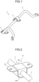
- FIG. 1 is a perspective view illustrating an example of a stabilizer manufactured in the first embodiment of the present invention.
- FIG. 2 is a diagram illustrating a configuration, in the vicinity of a bushing member, of the stabilizer illustrated in FIG. 1 .
- a stabilizer 1 is made of a metal or various fibers (for example, carbon fibers).
- the stabilizer 1 includes a body portion 2 having both ends bent and a central portion extending linearly, and a bushing member 3 attached to the body portion 2.
- the body portion 2 extends in a columnar shape, for example, a cylindrical shape, and both ends thereof are bent.
- the body portion 2 may be solid or hollow.
- one end of the stabilizer 1 is connected to one suspension of suspensions located at the left and right, and the other end of the stabilizer 1 is connected to the other suspension. At this time, each end is fixed to the suspension via a through hole.
- the stabilizer 1 is fixed also to the vehicle body via the bushing member 3.
- the stabilizer 1 is produced by processing a base material. For example, a columnar base material is bent, and then, both ends are pressurized to form a planar shape, and a through hole is formed at each end.
- the bushing member 3 includes a bushing 31 and a bracket 32.
- the bracket 32 is attached to the vehicle body via a screw or the like to support the body portion 2 via the bushing 31.
- the bushing 31 is made using an elastic material such as rubber or an elastic resin, and functions as a damping member that reduces vibration or the like of the stabilizer 1 transmitted from a road surface or the like.
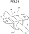
- the bushing 31 includes two members (a first member 301 and a second member 302).
- the bushing 31 is formed by sandwiching the body portion 2 between the first member 301 and the second member 302 and bonding the first member 301 and the second member 302 to the body portion 2.
- FIG. 3 is a flowchart illustrating the flow of a bushing bonding process according to the first embodiment.
- Step S101 adhesive application process
- the adhesive is applied to surfaces of the first member 301 and the second member 302 to be bonded to the body portion.
- the first member 301 and the second member 302 are subjected to a drying process.
- the first member 301 and the second member 302 are set in a bonding jig. The bonding jig will be described later.
- Step S102 heat treatment process
- an IH coil is used to heat a region including the bonded portion of the bushing 31 in the body portion 2.
- the body portion 2 is heated by applying heat for about several tens of seconds, for example.
- the temperature for the heat treatment is appropriately set according to the type of the bushing 31 or the adhesive.
- the body portion 2 Before the heat treatment, the body portion 2 may be subjected to a surface treatment for improving the adhesiveness by plasma treatment.
- Step S103 bushing assembly process.
- a load for crimping the first member 301 and the second member 302 onto the body portion 2 is applied by the bonding jig.
- the order of the heat treatment process and the bushing assembly process may be reversed.
- Step S104 crimping and holding process.
- the assembled state is held for the time it takes to complete the bonding, for example.
- the body portion 2 and the bushing 31 are bonded to each other by the pressure and the heat of the body portion 2.
- Examples of the bonding mode include vulcanization bonding.
- the bonding jig is removed from the bushing 31, so that the stabilizer 1 in which the bushing 31 is fixed to the body portion 2 is obtained.
- the bracket 32 is attached to the bushing 31.
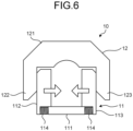
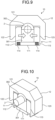
- FIGS. 4 , 6 , 7 , and 9 are plan views for explanation of a configuration of a bonding jig for bonding a bushing to a body portion in the first embodiment.
- FIGS. 5 , 8 , and 10 are perspective views for explanation of a configuration of a bonding jig for bonding a bushing to a body portion in the first embodiment.
- FIGS. 4 to 6 are diagrams illustrating only a bonding jig.
- FIGS. 7 to 10 are diagrams illustrating a bonding jig to which first and second members of a bushing are attached.
- a bonding jig 10 includes a first bonding member 11 and a second bonding member 12.
- the first member 301 and the second member 302 are cramped onto the body portion 2 by covering the first bonding member 11 with the second bonding member 12.
- an air cylinder is used to pressurize the first bonding member 11 and the second bonding member 12.
- the first bonding member 11 includes a bottom surface portion 111 on which the first member 301 is placed, a first wall portion 112 and a second wall portion 113 which are erected, with respect to the bottom surface portion 111, from both ends of the bottom surface portion 111, and coil springs 114 which bias the wall portions in directions away from the bottom surface portion 111.
- the second bonding member 12 includes a body portion 121 that holds the second member 302, and a first wall portion 122 and a second wall portion 123 that are erected, with respect to the body portion 121, from both ends of the body portion 121.
- a distance between an outer wall of the first wall portion 112 and an outer wall of the second wall portion 113 is denoted by d 1
- a distance between an inner wall of the first wall portion 122 and an inner wall of the second wall portion 123 is denoted by d 2
- a distance between an inner wall of the first wall portion 112 and an inner wall of the second wall portion 113 is denoted by d 3
- a width of the first member 301 is denoted by d 4 (see FIG. 7 ).
- the distance d 1 is greater than the distance d 2
- the distance d 3 is greater than the width d 4 .
- the difference (d 1 - d 2 ) between the distance d 1 and the distance d 2 is set to be substantially equal to the difference (d 2 - d 4 ) between the distance d 2 and the width d 4 , for example.
- a distance between the inner wall of the first wall portion 112 and the inner wall of the second wall portion 113 is set to be substantially equal to the width d 4 , and the first wall portion 112 and the second wall portion 113 are brought into contact with or pressed into contact with the first member 301.
- the bonding jig 10 when the second bonding member 12 is placed on the first bonding member 11 (see FIG. 4 ), the first wall portion 122 and the second wall portion 123 come into contact with the first wall portion 112 and the second wall portion 113, respectively, which moves the first wall portion 112 and the second wall portion 113 toward the bottom surface portion 111. As a result, the distance (corresponding to the distance d 3 ) between the first wall portion 112 and the second wall portion 113 is shortened.
- the contact portions of the first wall portions 112 and 122 and the second wall portions 113 and 123 each have a tapered shape formed by chamfering corner portions, and, at the time of contact, the first wall portion 112 and the second wall portion 113 can be moved while being accommodated in the second bonding member 12.
- the tapered shape may be formed on at least one of the wall portions in contact with each other. For example, as long as one of the first wall portions 112 and 122 has a tapered shape, smooth operation can be achieved.
- the first wall portion 112 and the second wall portion 113 sandwich and hold the first member 301, so that the first member 301 can be positioned. Further, the movement of the first wall portion 112 and the second wall portion 113 is caused by the contact to the second bonding member 12; therefore, the relative positional relationship between the positions of the first wall portion 112 and the second wall portion 113 and the position of the second bonding member 12 can be fixed. This enables crimping the first member 301 and the second member 302 onto the body portion 2 while a relative misalignment between the position of the first member 301 held by the first bonding member 11 and the position of the second member 302 held by the second bonding member 12 can be controlled.
- the first wall portion 112 and the second wall portion 113 move in directions away from each other by the biasing force of the coil springs 114, which forms a gap between the first wall portion 112 and the first member 301 as well as between the second wall portion 113 and the first member 301.
- the gaps allow the first member 301 to be easily removed from the first bonding member 11.
- the coil springs 114 are included in a switching mechanism that switches, in a space where the first bonding member 11 holds the first member 301, between a first state in which a gap is formed between the first bonding member 11 and a part of the side surface of the first member 301, which is continuous with the crimping surface with the second member 302, and a second state in which the gap is filled to control the position of the first member 301.
- the gap between the first member 301 and the first bonding member 11 is filled due to the movement of the first wall portion 112 and the second wall portion 113.
- the first embodiment when the constituent members of the bushing 31 are attached to and detached from the bonding members, a gap is provided between the first wall portion 112 and the first member 301 as well as between the second wall portion 113 and the first member 301 to enhance the workability.
- the first member 301 and the second member 302 are crimped onto the body portion 2
- the first member 301 is sandwiched by the first wall portion 112 and the second wall portion 113 to fix the position, which enables crimping while misalignment of the crimping surfaces of the first member 301 and the second member 302 with respect to the body portion 2 is prevented.
- a configuration without the coil springs 114 is possible as long as the first wall portion 112 and the second wall portion 113 can move in directions away from each other under their own weights.
- the adhesive may be applied to the body portion 2, or the adhesive may be applied to each of the bushing 31 and the body portion 2.
- FIG. 11 is a plan view for explanation of a configuration of a bonding jig for bonding a bushing to a body portion in the second embodiment.
- the same portions as those of the bonding jig 10 according to the first embodiment are denoted by the same reference numerals.
- a bonding jig 10A according to the second embodiment includes a first bonding member 11A and a second bonding member 12A.
- the first member 301 and the second member 302 are cramped onto the body portion 2 by covering the first bonding member 11A with the second bonding member 12A.
- the first bonding member 11A includes the bottom surface portion 111 on which the first member 301 is placed, the first wall portion 112 and the second wall portion 113 which are erected, with respect to the bottom surface portion 111, from both ends of the bottom surface portion 111, and the coil springs 114 which bias the first wall portion 112 and the second wall portion 113 in directions away from the bottom surface portion 111.
- holes 112a and 113a are formed in the first wall portion 112 and the second wall portion 113, respectively.
- the holes 112a and 113a are bored from ends of the first wall portion 112 and the second wall portion 113 opposite to ends thereof connected to the bottom surface portion 111.
- Each of the holes 112a and 113a has a hole shape extending obliquely toward the outer wall.
- the second bonding member 12A includes a body portion 124 that holds the second member 302, and a first pin 125 and a second pin 126 that extend from both ends of the body portion 124.
- the first pin 125 and the second pin 126 extend opposite to each other depending on the inclination of the holes 112a and 113a.
- the first pin 125, the second pin 126, and the holes 112a and 113a constitute a switching mechanism.
- a distance (corresponding to the distance d 3 ) between the inner wall of the first wall portion 112 and the inner wall of the second wall portion 113 is set to be greater than the width (distance d 4 illustrated in FIG. 7 ) of the first member 301, and when the second bonding member 12A is placed on the first bonding member 11A, the distance between the inner wall of the first wall portion 112 and the inner wall of the second wall portion 113 is set to be substantially equal to the width d 4 .
- the first pin 125 and the second pin 126 are inserted into the holes 112a and 113a, respectively.
- the first pin 125 and the second pin 126 slide on the wall surfaces of the holes 112a and 113a to move the first wall portion 112 and the second wall portion 113 toward the bottom surface portion 111.
- the distance (corresponding to the distance d 3 ) between the first wall portion 112 and the second wall portion 113 is shortened.
- the change in distance enables fixing the positional relationship between the positions of the first wall portion 112 and the second wall portion 113 and the position of the second bonding member 12, and enables the first member 301 to be easily attached to and detached from the first bonding member 11.
- the second embodiment when the constituent members of the bushing 31 are attached to and detached from the bonding members, a gap is provided between the first wall portion 112 and the first member 301 as well as between the second wall portion 113 and the first member 301 to enhance the workability.
- the first member 301 and the second member 302 are crimped onto the body portion 2
- the first member 301 is sandwiched by the first wall portion 112 and the second wall portion 113 to fix the position, which enables crimping while misalignment of the crimping surfaces of the first member 301 and the second member 302 with respect to the body portion 2 is prevented.
- FIGS. 12 and 13 are plan views for explanation of a configuration of a bonding jig for bonding a bushing to a body portion in the third embodiment.
- a configuration of a first bonding member will be described.
- a first bonding member 11B includes a bottom surface portion 115 on which the first member 301 is placed, a first wall portion 116A and a second wall portion 116B which are placed on the bottom surface portion 115, and a first moving mechanism 117A and a second moving mechanism 117B which move the first wall portion 116A and the second wall portion 116B, respectively.
- the first wall portion 116A and the second wall portion 116B are provided so as to be movable in directions toward or away from each other.
- the first moving mechanism 117A and the second moving mechanism 117B correspond to a switching mechanism.
- the first moving mechanism 117A includes a fulcrum portion 117a fixed to the bottom surface portion 115, an effort point portion 117b to which a load from a second bonding member is applied, and an action portion 117c that moves the first wall portion 116A depending on the load applied to the effort point portion 117b.
- the fulcrum portion 117a and the effort point portion 117b are connected by a connecting member, and the effort point portion 117b and the action portion 117c are connected by a connecting member.
- the effort point portion 117b moves toward the bottom surface portion 115.
- the movement of the effort point portion 117b moves the action portion 117c in a direction away from the fulcrum portion 117a.
- the first wall portion 116A moves toward the second wall portion 116B.
- the second moving mechanism 117B also has the same configuration as that of the first moving mechanism 117A.
- the effort point portion 117b moves toward the bottom surface portion 115.
- the movement of the effort point portion 117b moves the action portion 117c in a direction away from the fulcrum portion 117a.
- the second wall portion 116B moves toward the first wall portion 116A.
- the first moving mechanism 117A is configured to maintain the shape in a state where the first wall portion 116A and the second wall portion 116B are spaced from each other as illustrated in FIG. 12 .
- the first wall portion 116A and the second wall portion 116B are biased in directions away from each other by a biasing member (not illustrated).
- the second bonding member may be any member as long as it can hold the second member 302 and abut on the effort point portion 117b to apply a load.
- the application is made possible by adjusting the positions of the first wall portion 122 and the second wall portion 123 of the second bonding member 12 and the positions of the first pin 125 and the second pin 126 of the second bonding member 12A.
- a distance (corresponding to the distance d 3 ) between an inner wall of the first wall portion 116A and an inner wall of the second wall portion 116B is set to be greater than the width (distance d 4 illustrated in FIG. 7 ) of the first member 301, and when the second bonding member is placed on the first bonding member 11B, a distance between the inner wall of the first wall portion 112 and the inner wall of the second wall portion 113 is set to be substantially equal to the width d 4 .
- the distance (corresponding to the distance d 3 ) between the first wall portion 116A and the second wall portion 116B is shortened.
- the change in distance enables fixing the positional relationship between the positions of the first wall portion 116A and the second wall portion 116B and the position of the second bonding member, and enables the first member 301 to be easily attached to and detached from the first bonding member 11.
- the third embodiment when the constituent members of the bushing 31 are attached to and detached from the bonding members, a gap is provided between the first wall portion 116A and the first member 301 as well as between the second wall portion 116B and the first member 301 to enhance the workability.
- the first member 301 and the second member 302 are crimped onto the body portion 2
- the first member 301 is sandwiched by the first wall portion 116A and the second wall portion 116B to fix the position, which enables crimping while misalignment of the crimping surfaces of the first member 301 and the second member 302 with respect to the body portion 2 is prevented.
- FIGS. 14 and 15 are plan views for explanation of a configuration of a bonding jig for bonding a bushing to a body portion in the fourth embodiment.
- a first bonding member 11C includes a bottom surface portion 115 on which the first member 301 is placed, the first wall portion 116A and the second wall portion 116B which are placed on the bottom surface portion 115, and a first moving mechanism 117C and a second moving mechanism 117D which move the first wall portion 116A and the second wall portion 116B, respectively.
- the first moving mechanism 117C and the second moving mechanism 117D correspond to a switching mechanism.
- the first moving mechanism 117C includes a fulcrum portion 117d fixed to the bottom surface portion 115, an effort point portion 117e to which a load from a second bonding member is applied, and an action portion 117f that moves the first wall portion 116A depending on the load applied to the effort point portion 117e.
- the fulcrum portion 117d and the action portion 117c are connected by a connecting member 117g.
- the effort point portion 117e moves toward the bottom surface portion 115.
- the effort point portion 117e moves to come into contact with the connecting member 117g, and pushes down the connecting member 117g.
- the connecting member 117g rotates around the fulcrum portion 117d to move the action portion 117f.
- the action portion 117f slides with respect to the first wall portion 116A. As a result, the first wall portion 116A moves toward the second wall portion 116B.
- the second moving mechanism 117D also has the same configuration as that of the first moving mechanism 117C.
- the effort point portion 117e moves toward the bottom surface portion 115.
- the movement of the effort point portion 117e slides the action portion 117f with respect to the second wall portion 116B.
- the second wall portion 116B moves toward the first wall portion 116A.
- the second bonding member may be any member as long as it can hold the second member 302 and abut on the effort point portion 117e to apply a load.
- the application is made possible by adjusting the positions of the first wall portion 122 and the second wall portion 123 of the second bonding member 12 and the positions of the first pin 125 and the second pin 126 of the second bonding member 12A.
- the effort point portion 117e may be provided at an end of the second bonding member.
- a distance (corresponding to the distance d 3 ) between the inner wall of the first wall portion 116A and the inner wall of the second wall portion 116B is set to be greater than the width (distance d 4 illustrated in FIG. 7 ) of the first member 301, and when the second bonding member is placed on the first bonding member 11B, a distance between the inner wall of the first wall portion 112 and the inner wall of the second wall portion 113 is set to be substantially equal to the width d 4 .
- the distance (corresponding to the distance d 3 ) between the first wall portion 116A and the second wall portion 116B is shortened.
- the change in distance enables fixing the positional relationship between the positions of the first wall portion 116A and the second wall portion 116B and the position of the second bonding member, and enables the first member 301 to be easily attached to and detached from the first bonding member 11.
- the fourth embodiment when the constituent members of the bushing 31 are attached to and detached from the bonding members, a gap is provided between the first wall portion 116A and the first member 301 as well as between the second wall portion 116B and the first member 301 to enhance the workability.
- the first member 301 and the second member 302 are crimped onto the body portion 2
- the first member 301 is sandwiched by the first wall portion 116A and the second wall portion 116B to fix the position, which enables crimping while misalignment of the crimping surfaces of the first member 301 and the second member 302 with respect to the body portion 2 is prevented.
- FIG. 16 is a plan view for explanation of a configuration of a bonding jig for bonding a bushing to a body portion in the fifth embodiment.
- the same portions as those of the bonding jig 10 according to the first embodiment are denoted by the same reference numerals.
- a bonding jig 10B according to the fifth embodiment includes a first bonding member 11D, a second bonding member 12B, and a wedge 13.
- the wedge 13 enters the first bonding member 11D to crimp the first member 301 and the second member 302 onto the body portion 2.
- the first bonding member 11D has a body portion 115A in which a housing portion 115a for accommodating the first member 301 is formed.
- the housing portion 115a includes a bottom surface 115b on which the first member 301 is placed and a side surface 115c extending obliquely in a direction of the expansion of the internal space with respect to the bottom surface 115b.
- the second bonding member 12B has the body portion 124 that holds the second member 302.
- the wedge 13 has a first claw portion 131 and a second claw portion 132 extending in a conical shape.
- the first claw portion 131 and the second claw portion 132 are designed to be equal to the width (distance d 4 illustrated in FIG. 7 ) of the first member 301 when entering the first bonding member 11D.
- the wedge 13 (the first claw portion 131 and the second claw portion 132) constitutes a switching mechanism.
- the shortest distance between the facing side surfaces 115c is the distance between the ends continuous to the bottom surface 115b, and is equal to the first member 301.
- the shortest distance between the facing side surfaces 115c is the distance between the ends continuous to the bottom surface 115b, and is equal to the first member 301 (width d 4 ).
- the longest distance between the facing side surfaces 115c is a distance between the ends (openings) on the opposite side to the bottom surface 115b side, and is greater than the width of the first member 301 (distance d 4 illustrated in FIG. 7 ) (corresponding to distance d 3 ).
- the first claw portion 131 and the second claw portion 132 enter the housing portion 115a.
- the first claw portion 131 and the second claw portion 132 are inserted into the housing portion 115a, so that the distance (corresponding to the distance d 3 ) between the wall surfaces in the housing portion 115a is shortened.
- the change in distance enables fixing the positional relationship between the position of the first member 301 in the first bonding member 11D and the position of the second member 302 in the second bonding member 12, and enables the first member 301 to be easily attached to and detached from the first bonding member 11.
- the fifth embodiment when the constituent members of the bushing 31 are attached to and detached from the bonding members, a gap is provided between the first member 301 and the housing portion 115a to enhance the workability.
- the first member 301 and the second member 302 are crimped onto the body portion 2, the first member 301 is sandwiched by the first claw portion 131 and the second claw portion 132 to fix the position, which enables crimping while misalignment of the crimping surfaces of the first member 301 and the second member 302 with respect to the body portion 2 is prevented.
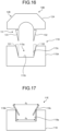
- FIG. 17 is a plan view for explanation of a configuration of a bonding jig for bonding a bushing to a body portion in the sixth embodiment.
- a configuration of a first bonding member will be described.
- a first bonding member 11E has a body portion 118 in which a housing portion 118a for accommodating the first member 301 is formed.
- the body portion 118 includes a first plate 118b and a second plate 118c that are provided at an open end of the housing portion 118a and are rotatable about a corner of the housing portion 118a as a fulcrum.
- the first plate 118b and the second plate 118c may be connected so as not to be detached from the body portion 118, or may be separated from the body portion 118.
- the first plate 118b and the second plate 118c constitute a switching mechanism.
- the first plate 118b and the second plate 118c are inclined so that the outer sides thereof extend beyond the housing portion 118a in a state where a load other than gravity is not applied, which allows the first member 301 to be easily housed.
- the first plate 118b and the second plate 118c are pulled out, which creates a gap corresponding to the size of the plate thickness between the housing portion 118a and the first member 301, so that the first member 301 is easily pulled out from the housing portion 118a.
- the second bonding member may be any member as long as the second bonding member holds the second member 302 and does not interfere with the first plate 118b and the second plate 118c when covering the first bonding member 11E.
- the application is made possible by adjusting the positions of the first wall portion 122 and the second wall portion 123 of the second bonding member 12.
- the maximum distance d 5 between the first plate 118b and the second plate 118c is greater than the width of the first member 301 (distance d 4 illustrated in FIG. 7 ). Setting is so made that a distance d 6 between the first plate 118b and the second plate 118c is substantially equal to the width d 4 when the first plate 118b and the second plate 118c are housed in the housing portion 118a.
- the distance between the first plate 118b and the second plate 118c is shortened.
- the change in distance enables fixing the positional relationship between the position of the first member 301 by the first plate 118b and the second plate 118c and the position of the second member 302 of the second bonding member, and enables the first member 301 to be easily attached to and detached from the first bonding member 11.
- the sixth embodiment when the constituent members of the bushing 31 are attached to and detached from the bonding members, a gap is provided between the housing portion 118a and the first member 301 to enhance the workability.
- the first member 301 and the second member 302 are crimped onto the body portion 2, the first member 301 is sandwiched by the first plate 118b and the second plate 118c to fix the position, which enables crimping while misalignment of the crimping surfaces of the first member 301 and the second member 302 with respect to the body portion 2 is prevented.
- FIGS. 18 and 19 are plan views for explanation of a configuration of a bonding jig for bonding a bushing to a body portion in the seventh embodiment.
- a configuration of a first bonding member will be described.
- a first bonding member 11F according to the seventh embodiment includes a body portion 119a, and a first holding portion 119b and a second holding portion 119c formed by bending a plate-like member.
- the first holding portion 119b rotates around a shaft 119d.
- the second holding portion 119c rotates around a shaft 119e.
- the shafts 119d and 119e are fixed to the body portion 119a and attached to bent portions of the respective holding portions.
- the first holding portion 119b and the second holding portion 119c accommodate the first member 301 between portions (hereinafter, referred to as wall portions 119f and 119g) rising and extending from the body portion 119a.
- the first holding portion 119b and the second holding portion 119c constitute a switching mechanism.
- the first holding portion 119b and the second holding portion 119c are inclined so that the wall portions 119f and 119g extend outward in a state where a load other than gravity is not applied, which allows the first member 301 to be easily housed and taken out (see FIG. 18 ).
- the first holding portion 119b and the second holding portion 119c rotate, and the wall portions 119f and 119g sandwich the first member 301 therebetween (see FIG. 19 ).
- the second bonding member may be any member as long as the second bonding member holds the second member 302 and does not interfere with the first holding portion 119b and the second holding portion 119c when covering the first bonding member 11F.
- the application is made possible by adjusting the positions of the first wall portion 122 and the second wall portion 123 of the second bonding member 12.
- the maximum distance d 7 between the wall portions 119f and 119g is greater than the width of the first member 301 (distance d 4 illustrated in FIG. 7 ). Setting is so made that a distance d 8 between the wall portions 119f and 119g is substantially equal to the width d 4 when the first member 301 is placed and the first holding portion 119b and the second holding portion 119c rotate.
- the distance between the wall portions 119f and 119g is shortened.
- the change in distance enables fixing the positional relationship between the position of the first member 301 by the first holding portion 119b and the second holding portion 119c and the position of the second member 302 of the second bonding member, and enables the first member 301 to be easily attached to and detached from the first bonding member 11.
- the seventh embodiment when the constituent members of the bushing 31 are attached to and detached from the bonding members, a gap is provided between the first holding portion 119b (wall portion 119f) and the first member 301 as well as between the second holding portion 119c (wall portion 119g) and the first member 301 to enhance the workability.
- the first member 301 and the second member 302 are crimped onto the body portion 2, the first member 301 is sandwiched by the wall portions 119f and 119g to fix the position, which enables crimping while misalignment of the crimping surfaces of the first member 301 and the second member 302 with respect to the body portion 2 is prevented.
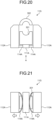
- FIG. 20 is a plan view for explanation of a configuration of a bonding jig for bonding a bushing to a body portion in the eighth embodiment.
- FIG. 21 is a plan view illustrating a configuration of the bonding jig viewed from a direction of an arrow A illustrated in FIG. 20 .
- a configuration of a first bonding member will be described.
- a first bonding member 11G includes a bottom surface portion 111A on which the first member 301 is placed, a first wall portion 112A and a second wall portion 113A which are erected, with respect to the bottom surface portion 111A, on the side of both ends of the bottom surface portion 111A, and leaf springs 114A which bias the wall portions in directions away from the bottom surface portion 111A.
- the leaf springs 114A are included in a switching mechanism that switches, in a space where the first bonding member 11G holds the first member 301, between a first state in which a gap is formed between the first bonding member 11G and a part of the side surface of the first member 301, which is continuous with the crimping surface with the second member 302, and a second state in which the gap is filled to control the position of the first member 301.
- the gap between the first member 301 and the first bonding member 11G is changed due to the movement of the first wall portion 112A and the second wall portion 113A.
- the leaf spring 114A has a central portion connected to the bottom surface portion 111A and both ends connected to the first wall portion 112A (or the second wall portion 113A).
- the leaf springs 114A bias the wall portions connected thereto in directions away from the bottom surface portion 111A.
- the leaf springs 114A are fixed to the bottom surface portion 111A and the wall portion by screwing, welding, or the like.
- the second bonding member may be any member as long as the second bonding member holds the second member 302 and comes into contact with the first wall portion 112A and the second wall portion 113A to move the first wall portion 112A and the second wall portion 113A toward the bottom surface portion 111A when covering the first bonding member 11G.
- the application is made possible by adjusting the positions of the first wall portion 122 and the second wall portion 123 of the second bonding member 12.
- a distance between the first wall portion 112A and the second wall portion 113A is greater than the width of the first member 301 (width d 4 illustrated in FIG. 7 ). Setting is so made that the distance between the first wall portion 112A and the second wall portion 113A is substantially equal to the width d 4 when the second bonding member is attached to the first bonding member.
- the eighth embodiment when the constituent members of the bushing 31 are attached to and detached from the bonding members, a gap is provided between the first wall portion 112A and the first member 301 as well as between the second wall portion 113A and the first member 301 to enhance the workability.
- the first member 301 and the second member 302 are crimped onto the body portion 2
- the first member 301 is sandwiched by the first wall portion 112A and the second wall portion 113A to fix the position, which enables crimping while misalignment of the crimping surfaces of the first member 301 and the second member 302 with respect to the body portion 2 is prevented.
- FIG. 22 is a plan view for explanation of a configuration of a bonding jig for bonding a bushing to a body portion in the ninth embodiment.
- a configuration of a first bonding member will be described.
- a first bonding member 11H according to the ninth embodiment includes the bottom surface portion 111A on which the first member 301 is placed, a first wall portion 112B and a second wall portion 113B which are erected, with respect to the bottom surface portion 111A, on the side of both ends of the bottom surface portion 111A, and a first inclined portion 141 and a second inclined portion 142 that movably hold the wall portions, respectively.
- the first inclined portion 141 and the second inclined portion 142 extend obliquely downward as being away from the bottom surface portion 111A. Therefore, the first wall portion 112B and the second wall portion 113B move in a direction away from the bottom surface portion 111A under their own weights in a state where a load other than gravity is not applied.
- the first inclined portion 141 and the second inclined portion 142 are included in a switching mechanism that switches, in a space where the first bonding member 11H holds the first member 301, between a first state in which a gap is formed between the first bonding member 11H and a part of the side surface of the first member 301, which is continuous with the crimping surface with the second member 302, and a second state in which the gap is filled to control the position of the first member 301.
- the second bonding member may be any member as long as the second bonding member holds the second member 302 and comes into contact with the first wall portion 112B and the second wall portion 113B to move the first wall portion 112B and the second wall portion 113B toward the bottom surface portion 111A when covering the first bonding member 11H.
- the application is made possible by adjusting the positions of the first wall portion 122 and the second wall portion 123 of the second bonding member 12.
- the first wall portion 112B and the second wall portion 113B rise along the first inclined portion 141 and the second inclined portion 142, respectively, and approach the bottom surface portion 111A.
- the first wall portion 112B and the second wall portion 113B fall along the first inclined portion 141 and the second inclined portion 142, respectively, under their own weights so as to be away from the bottom surface portion 111A.
- a distance between the first wall portion 112B and the second wall portion 113B is greater than the width of the first member 301 (width d 4 illustrated in FIG. 7 ). Setting is so made that the distance between the first wall portion 112B and the second wall portion 113B is substantially equal to the width d 4 when the second bonding member is attached to the first bonding member.
- the ninth embodiment when the constituent members of the bushing 31 are attached to and detached from the bonding members, a gap is provided between the first wall portion 112B and the first member 301 as well as between the second wall portion 113B and the first member 301 to enhance the workability.
- the first member 301 and the second member 302 are crimped onto the body portion 2
- the first member 301 is sandwiched by the first wall portion 112B and the second wall portion 113B to fix the position, which enables crimping while misalignment of the crimping surfaces of the first member 301 and the second member 302 with respect to the body portion 2 is prevented.
- FIG. 23 is a plan view for explanation of a configuration of a bonding jig for bonding a bushing to a body portion in the tenth embodiment.
- a configuration of a first bonding member will be described.
- a first bonding member 11I includes a bottom surface portion 111B on which the first member 301 is placed, a first wall portion 112C and a second wall portion 113C that are erected movably on the bottom surface portion 111B, and a first magnetic portion 143 and a second magnetic portion 144 that generate force to move the wall portions.
- the first wall portion 112C and the second wall portion 113C are made of a magnetic material.
- the first magnetic portion 143 and the second magnetic portion 144 are configured using, for example, an electromagnet, and the energization thereto is controlled by a control device (not illustrated). Therefore, the first wall portion 112C and the second wall portion 113C move in a direction away from the bottom surface portion 111A depending on a state in which the first magnetic portion 143 and the second magnetic portion 144 are energized. For example, when the first magnetic portion 143 and the second magnetic portion 144 are energized, the first wall portion 112C and the second wall portion 113C move in directions away from each other due to the magnetic force generated by the first magnetic portion 143 and the second magnetic portion 144.
- the first magnetic portion 143 and the second magnetic portion 144 are included in a switching mechanism that switches, in a space where the first bonding member 11I holds the first member 301, between a first state in which a gap is formed between the first bonding member 11I and a part of the side surface of the first member 301, which is continuous with the crimping surface with the second member 302, and a second state in which the gap is filled to control the position of the first member 301.
- the second bonding member may be any member as long as the second bonding member holds the second member 302 and comes into contact with the first wall portion 112C and the second wall portion 113C to move the first wall portion 112C and the second wall portion 113C toward the bottom surface portion 111B when covering the first bonding member 11I.
- the application is made possible by adjusting the positions of the first wall portion 122 and the second wall portion 123 of the second bonding member 12.
- the first magnetic portion 143 and the second magnetic portion 144 may be constantly energized, or may be energized at necessary timing.
- the second bonding member without the first wall portion 122 and the second wall portion 123 is possible.
- a distance between the first wall portion 112C and the second wall portion 113C is greater than the width of the first member 301 (width d 4 illustrated in FIG. 7 ). Setting is so made that the distance between the first wall portion 112C and the second wall portion 113C is substantially equal to the width d 4 when the second bonding member is attached to the first bonding member.
- the tenth embodiment when the constituent members of the bushing 31 are attached to and detached from the bonding members, a gap is provided between the first wall portion 112C and the first member 301 as well as between the second wall portion 113C and the first member 301 to enhance the workability.
- the first member 301 and the second member 302 are crimped onto the body portion 2
- the first member 301 is sandwiched by the first wall portion 112C and the second wall portion 113C to fix the position, which enables crimping while misalignment of the crimping surfaces of the first member 301 and the second member 302 with respect to the body portion 2 is prevented.
- FIG. 24 is a plan view for explanation of a configuration of a bonding jig for bonding a bushing to a body portion in the eleventh embodiment.
- a configuration of a first bonding member will be described.
- a first bonding member 11J according to the eleventh embodiment includes the bottom surface portion 111 on which the first member 301 is placed, a first wall portion 112D and a second wall portion 113D which are erected, with respect to the bottom surface portion 111, on the side of both ends of the bottom surface portion 111, and a first screw portion 145 and a second screw portion 146 that movably hold the wall portions, respectively.
- the first screw portion 145 has a rod shape extending from the bottom surface portion 111 and penetrates the first wall portion 112D.
- the first screw portion 145 is formed with a screw thread and is screwed to the first wall portion 112D. Rotation of the first screw portion 145 around the longitudinal axis moves the first wall portion 112D in the longitudinal axis direction. The moving direction of the first wall portion 112D is determined depending on the rotating direction of the first screw portion 145.
- the first screw portion 145 may be manually rotated by a user, or may be electrically rotated by a motor or the like.
- the second screw portion 146 extends from the bottom surface portion 111 in a direction opposite to the first screw portion 145 and penetrates the second wall portion 113D.
- the second screw portion 146 is formed with a screw thread similarly to the first screw portion 145, and rotates to move the second wall portion 113D.
- the first screw portion 145 and the second screw portion 146 are included in a switching mechanism that switches, in a space where the first bonding member 11J holds the first member 301, between a first state in which a gap is formed between the first bonding member 11J and a part of the side surface of the first member 301, which is continuous with the crimping surface with the second member 302, and a second state in which the gap is filled to control the position of the first member 301.
- the second bonding member may be any member as long as the second bonding member holds the second member 302 and can bring the second member 302 into contact with the first member 301 held by the first bonding member 11J when covering the first bonding member 11J.
- the first screw portion 145 and the second screw portion 146 are rotated to move the first wall portion 112D and the second wall portion 113D toward the bottom surface portion 111.
- the first screw portion 145 and the second screw portion 146 are rotated to move the first wall portion 112D and the second wall portion 113D in a direction away from the bottom surface portion 111.
- a distance between the first wall portion 112D and the second wall portion 113D is greater than the width of the first member 301 (width d 4 illustrated in FIG. 7 ). Setting is so made that the distance between the first wall portion 112D and the second wall portion 113D is substantially equal to the width d 4 when the first member 301 and the second member 302 are attached to each other.
- the eleventh embodiment when the constituent members of the bushing 31 are attached to and detached from the bonding members, a gap is provided between the first wall portion 112D and the first member 301 as well as between the second wall portion 113D and the first member 301 to enhance the workability.
- the first member 301 and the second member 302 are crimped onto the body portion 2
- the first member 301 is sandwiched by the first wall portion 112D and the second wall portion 113D to fix the position, which enables crimping while misalignment of the crimping surfaces of the first member 301 and the second member 302 with respect to the body portion 2 is prevented.
- FIG. 25 is a plan view for explanation of a configuration of a bonding jig for bonding a bushing to a body portion in the twelfth embodiment.
- a configuration of a first bonding member will be described.
- a first bonding member 11K includes a bottom surface portion 111C on which the first member 301 is placed, the first wall portion 112A and the second wall portion 113A which are erected, with respect to the bottom surface portion 111C, on the side of both ends of the bottom surface portion 111C, and a link mechanism 15 that movably holds the wall portions.
- the link mechanism 15 includes an operation portion 151 provided on the bottom surface portion 111C, a first support portion 152 attached to the first wall portion 112A, a second support portion 153 attached to the second wall portion 113A, a first link 154 connecting the operation portion 151 and the first support portion 152, and a second link 155 connecting the operation portion 151 and the second support portion 153.
- the first support portion 152 and the second support portion 153 move in directions away from each other via the first link 154 and the second link 155. This also moves the wall portions supported by the support portions.
- the link mechanism 15 constitutes a switching mechanism that switches, in a space where the first bonding member 11K holds the first member 301, between a first state in which a gap is formed between the first bonding member 11K and a part of the side surface of the first member 301, which is continuous with the crimping surface with the second member 302, and a second state in which the gap is filled to control the position of the first member 301.
- the second bonding member may be any member as long as the second bonding member holds the second member 302 and can bring the second member 302 into contact with the first member 301 held by the first bonding member 11K when covering the first bonding member 11K.
- the operation portion 151 when the second bonding member is attached, the operation portion 151 is pushed to move the first wall portion 112A and the second wall portion 113A in directions toward each other. After the bonding process, the pressing of the operation portion 151 is released to move the first wall portion 112A and the second wall portion 113A in directions away from each other.
- a distance between the first wall portion 112A and the second wall portion 113A is greater than the width of the first member 301 (width d 4 illustrated in FIG. 7 ). Setting is so made that the distance between the first wall portion 112A and the second wall portion 113A is substantially equal to the width d 4 in a state where a load other than gravity is not applied to the operation portion 151.
- the first member 301 and the second member 302 are crimped onto the body portion 2
- the first member 301 is sandwiched by the first wall portion 112A and the second wall portion 113A to fix the position, which enables crimping while misalignment of the crimping surfaces of the first member 301 and the second member 302 with respect to the body portion 2 is prevented.
- FIG. 26 is a plan view for explanation of a configuration of a bonding jig for bonding a bushing to a body portion in the thirteenth embodiment.
- a configuration of a first bonding member will be described.
- a first bonding member 11L according to the thirteenth embodiment includes a bottom surface portion 111D on which the first member 301 is placed, and a first wall portion 112E and a second wall portion 113E which are erected, with respect to the bottom surface portion 111D, on the side of both ends of the bottom surface portion 111D.
- the first wall portion 112E and the second wall portion 113E are formed with switching surfaces 112b and 113b, respectively.
- Each of the switching surfaces 112b and 113b constitutes a wall surface facing the bottom surface portion 111D and forms an acute angle with the wall surface facing the first member 301. Therefore, the first wall portion 112E and the second wall portion 113E are inclined in such a manner that the switching surfaces and the bottom surface portion 111D make a surface contact with each other under their own weights in a natural state where a load other than gravity is not applied.
- the wall surfaces of the first wall portion 112E and the second wall portion 113E facing the first member 301 are inclined, and a gap is formed between the first member 301 and each of the first wall portion 112E and the second wall portion 113E.
- the first wall portion 112E and the second wall portion 113E are included in a switching mechanism that switches, in a space where the first bonding member 11L holds the first member 301, between a first state in which a gap is formed between the first bonding member 11L and a part of the side surface of the first member 301, which is continuous with the crimping surface with the second member 302, and a second state in which the gap is filled to control the position of the first member 301.
- the second bonding member may be any member as long as the second bonding member holds the second member 302 and comes into contact with the first wall portion 112E and the second wall portion 113E to move the first wall portion 112E and the second wall portion 113E toward the bottom surface portion 111D when covering the first bonding member 11L.
- the application is made possible by adjusting the positions of the first wall portion 122 and the second wall portion 123 of the second bonding member 12.
- attaching the second bonding member rotates the first wall portion 112E and the second wall portion 113E, so that the switching surfaces 112b and 113b are spaced from the bottom surface portion 111D and the first wall portion 112E and the second wall portion 113E approach each other.
- the second bonding member is detached, in the first wall portion 112E and the second wall portion 113E, the first wall portion 112E and the second wall portion 113E rotate, the switching surfaces 112b and 113b come into contact with the bottom surface portion 111D, and the first wall portion 112E and the second wall portion 113E move away from each other.
- the maximum distance between the first wall portion 112E and the second wall portion 113E is greater than the width of the first member 301 (width d 4 illustrated in FIG. 7 ). Setting is so made that the distance between the first wall portion 112E and the second wall portion 113E is substantially equal to the width d 4 when the second bonding member is attached to the first bonding member 11L.
- the thirteenth embodiment when the constituent members of the bushing 31 are attached to and detached from the bonding members, a gap is provided between the first wall portion 112E and the first member 301 as well as between the second wall portion 113E and the first member 301 to enhance the workability.
- the first member 301 and the second member 302 are crimped onto the body portion 2
- the first member 301 is sandwiched by the first wall portion 112E and the second wall portion 113E to fix the position, which enables crimping while misalignment of the crimping surfaces of the first member 301 and the second member 302 with respect to the body portion 2 is prevented.
- FIG. 27 is a plan view for explanation of a configuration of a bonding jig for bonding a bushing to a body portion in the fourteenth embodiment.
- a configuration of a first bonding member will be described.
- a first bonding member 11M according to the fourteenth embodiment includes a bottom surface portion 111E on which the first member 301 is placed, and the first wall portion 112A and the second wall portion 113A which are erected, with respect to the bottom surface portion 111E, on the side of both ends of the bottom surface portion 111E.
- the bottom surface portion 111E has a tubular shape in which one end is bifurcated, an air flow path is formed inside, and the first member 301 is placed.
- the bottom surface portion 111E includes a first opening portion 111a, a second opening portion 111b that communicates with the first opening portion 111a, is provided at one bifurcated end, and faces the first wall portion 112A, and a third opening portion 111c that is provided at the other bifurcated end, and faces the second wall portion 113A. Air introduced into the first opening portion 111a or sucked from the first opening portion 111a adjusts air sucked or blown out from the second opening portion 111b and the third opening portion 111c.
- the first wall portion 112A and the second wall portion 113A move in directions away from each other.
- the first wall portion 112A and the second wall portion 113A move in directions toward each other.
- the bottom surface portion 111E is included in a switching mechanism that switches, in a space where the first bonding member 11M holds the first member 301, between a first state in which a gap is formed between the first bonding member 11M and a part of the side surface of the first member 301, which is continuous with the crimping surface with the second member 302, and a second state in which the gap is filled to control the position of the first member 301.
- the second bonding member may be any member as long as the second bonding member holds the second member 302 and can bring the second member 302 into contact with the first member 301 held by the first bonding member 11M when covering the first bonding member 11M.
- a distance between the first wall portion 112A and the second wall portion 113A is greater than the width of the first member 301 (width d 4 illustrated in FIG. 7 ). Setting is so made that the distance between the first wall portion 112A and the second wall portion 113A is substantially equal to the width d 4 when the first member 301 and the second member 302 are bonded together.
- the fourteenth embodiment when the constituent members of the bushing 31 are attached to and detached from the bonding members, a gap is provided between the first wall portion 112A and the first member 301 as well as between the second wall portion 113A and the first member 301 to enhance the workability.
- the first member 301 and the second member 302 are crimped onto the body portion 2
- the first member 301 is sandwiched by the first wall portion 112A and the second wall portion 113A to fix the position, which enables crimping while misalignment of the crimping surfaces of the first member 301 and the second member 302 with respect to the body portion 2 is prevented.
- FIG. 28 is a perspective view for explanation of a configuration of a bushing member in the fifteenth embodiment.
- a configuration of a bushing member will be described.
- a bushing member 3A includes a bushing 31 and a bracket 32.
- the bushing 31 is made using an elastic material such as rubber or an elastic resin, and functions as a damping member that reduces vibration or the like of the stabilizer 1 transmitted from a road surface or the like.
- the bushing 31 includes two members (a first member 301 and a second member 302).
- the first member 301 and the second member 302 constituting the bushing 31 are divided in a direction parallel to the longitudinal direction of the body portion 2 and orthogonal to the first embodiment.
- the members can be bonded to each other using the same bonding jig as in the first to fourteenth embodiments, and thus the same effect as in the first embodiment can be obtained.
- the present invention should not be limited only to the above-described embodiments.
- the present invention is applicable to a product manufactured by a thermal compression process.
- the heating member is not limited thereto, and known heating (e.g., heating by energization or heating by hot air) can be used, and can be appropriately selected depending on the heating efficiency or the like.
- the bonded member is not limited to the stabilizer.
- the present invention can be applied to any bonded member as long as the member is a bonded member that is interposed between the connection targets and to which a damping member for reducing vibration or the like between the connection targets is bonded, and a bonded member to which a damping member is bonded regardless of whether the bonded member is heated or unheated.
- the bonded member include a winding spring, a leaf spring, a torsion bar, and a disk spring in addition to the stabilizer.
- an insulator is used as the damping member.
- the present invention can include various embodiments and the like not described herein, and various design changes and the like can be made without departing from the technical idea specified by the claims.
- the bonding jig and the bonding method according to the present invention are suitable for preventing the reduction in workability while a damping member is reliably crimped onto a bonded member.
Landscapes
- Engineering & Computer Science (AREA)
- Mechanical Engineering (AREA)
- General Engineering & Computer Science (AREA)
- Manufacturing & Machinery (AREA)
- Chemical & Material Sciences (AREA)
- Chemical Kinetics & Catalysis (AREA)
- General Chemical & Material Sciences (AREA)
- Lining Or Joining Of Plastics Or The Like (AREA)
- Vehicle Body Suspensions (AREA)
- Adhesives Or Adhesive Processes (AREA)
Abstract
Description
- The present invention relates to a bonding jig and a bonding method.
- A stabilizer used in a vehicle or the like is attached to the vehicle to stabilize the posture of the vehicle. At a connection part of the stabilizer to the body of the vehicle, a bushing is provided as a damping member that reduces vibration or the like of the stabilizer transmitted from a road surface or the like, and the stabilizer and the body of the vehicle are connected via the bushing. The bushing is made using an elastic member such as rubber to suppress the transmission of vibration of the stabilizer to the body. Generally, a bushing bonded to the body of a stabilizer includes two members which are attached to a bonding jig, pressed by the bonding jig, and attached to the body of the stabilizer (see, for example,
- Patent Literature 1:
JP 2008-143376 A - Incidentally, in the bonding jig, in a case where a gap (clearance) is provided in a holding portion that holds a member in order to enhance the workability and the member is crimped onto the body of a stabilizer, the member is deformed and a part of the member enters the gap to spread out, which reduces the surface pressure on the body of the stabilizer. On the other hand, in a case where a space equivalent to the size of the member is formed as the holding portion, there is no clearance. Thus, it takes time and effort to attach and detach the member to and from the bonding jig, or the member cannot be appropriately attached or detached, which may reduce the workability. The bonding jig is required to ensure the surface pressure of each member of the bushing against the body portion of the stabilizer at the time of bonding, and not to reduce the workability at the time of installing the member on the jig or at the time of detaching the jig after bonding.
- The present invention has been made in view of the above, and an object of the present invention is to provide a bonding jig and a bonding method which make it possible to prevent the reduction in workability while a damping member is reliably crimped onto a bonded member. Solution to Problem
- To solve the above-described problem and achieve the object, a bonding jig according to the present invention for crimping and bonding first and second members constituting a damping member to a bonded member includes: a first bonding member configured to hold the first member; a second bonding member configured to hold the second member and cover the first bonding member to crimp the first and second members onto the bonded member; and a switching mechanism configured to switch, in a space where the first bonding member holds the first member, between a first state in which a gap is formed between the first bonding member and a part of a side surface of the first member continuous with a crimping surface with the second member and a second state in which the gap is filled to control a position of the first member.
- Moreover, in the above-described bonding jig according to the present invention, the first bonding member includes a bottom surface portion on which the first member is placed, and first and second wall portions erected from the bottom surface portion, the switching mechanism includes a spring configured to bias the first and second wall portions in directions away from each other, in the first state, the first and second wall portions are positioned in directions away from each other, and in the second state, the first and second wall portions are brought close to each other according to a load applied when the second bonding member is placed on the first bonding member.
- Moreover, in the above-described bonding jig according to the present invention, the first bonding member includes a bottom surface portion on which the first member is placed, and first and second wall portions erected from the bottom surface portion, the switching mechanism includes a hole formed on the first bonding member, and a pin provided on the second bonding member and inserted into the hole when the second bonding member is placed on the first bonding member, in the first state, the first and second wall portions are positioned in directions away from each other, and in the second state, the pin is inserted into the hole to bring the first and second wall portions close to each other.
- Moreover, in the above-described bonding jig according to the present invention, the first bonding member includes a bottom surface portion on which the first member is placed, and first and second wall portions erected from the bottom surface portion, the switching mechanism includes a fulcrum portion fixed to the bottom surface portion, an effort point portion configured to move due to a load applied according to a distance between the second bonding member and the first bonding member, and an action portion configured to move in synchronization with a movement of the effort point portion to move the first or second wall portion, the switching mechanism is provided for each of the first and second wall portions, in the first state, the first and second wall portions are positioned in directions away from each other, and in the second state, the first and second wall portions are brought close to each other.
- Moreover, in the above-described bonding jig according to the present invention, the fulcrum portion and the effort point portion are connected to each other in the switching mechanism, and the effort point portion and the action portion are connected to each other.
- Moreover, in the above-described bonding jig according to the present invention, the fulcrum portion and the action portion are connected by a connecting member in the switching mechanism, and the effort point portion moves to apply a load to the connecting member, and the action portion moves.
- Moreover, in the above-described bonding jig according to the present invention, the first bonding member includes a housing portion having a hole shape and configured to accommodate the first member, the switching mechanism includes first and second claw portions, and in the second state, the first and second claw portions are positioned in a gap between the housing portion and the first member to fill the gap.
- Moreover, in the above-described bonding jig according to the present invention, the first bonding member includes a housing portion having a hole shape and configured to accommodate the first member, and the switching mechanism includes first and second plates provided to be insertable into and removable from the housing portion and positioned in a gap between the housing portion and the first member.
- Moreover, in the above-described bonding jig according to the present invention, the first bonding member includes a bottom surface portion, and first and second holding portions formed by bending a plate-like member, placed on the bottom surface portion with one of bent portions facing each other, and configured to hold the first member, the switching mechanism is a shaft provided at each of bent positions of the first and second holding portions and is configured to rotatably hold the first and second holding portions, in the first state, wall portions erecting from the bottom surface portion in the first and second holding portions are positioned in directions away from each other, and in the second state, the wall portions are brought close to each other according to a load applied when the first member is placed on the first bonding member.
- Moreover, in the above-described bonding jig according to the present invention, the first bonding member includes a bottom surface portion on which the first member is placed, and first and second wall portions erected against the bottom surface portion, the switching mechanism includes a first inclined portion extending obliquely downward from the bottom surface portion and configured to movably support the first wall portion, and a second inclined portion extending obliquely downward from a side of the bottom surface portion opposite to the first inclined portion and configured to movably support the second wall portion, in the first state, the first and second wall portions are positioned in directions away from each other, and in the second state, the first and second wall portions are brought close to each other.
- Moreover, in the above-described bonding jig according to the present invention, the first bonding member includes a bottom surface portion on which the first member is placed, and first and second wall portions made of a magnetic material and erected from the bottom surface portion, the switching mechanism includes first and second magnetic portions configured to generate magnetic force, in the first state, the first and second wall portions are positioned in directions away from each other, and in the second state, the first and second wall portions are brought close to each other by the magnetic force generated by the first and second magnetic portions.
- Moreover, in the above-described bonding jig according to the present invention, the first bonding member includes a bottom surface portion on which the first member is placed, and first and second wall portions erected against the bottom surface portion, the switching mechanism includes a first screw portion having a rotatable rod shape and configured to move the first wall portion in a longitudinal axis direction by rotation, and a second screw portion having a rotatable rod shape and configured to move the second wall portion in the longitudinal axis direction by rotation, in the first state, the first and second wall portions are positioned in directions away from each other by the rotation of the first and second screw portions, and in the second state, the first and second wall portions are brought close to each other by the rotation of the first and second screw portions.
- Moreover, in the above-described bonding jig according to the present invention, the first bonding member includes a bottom surface portion on which the first member is placed, and first and second wall portions erected from the bottom surface portion, the switching mechanism includes a link mechanism configured to move first and second support portions configured to respectively support the first and second walls in directions toward each other or in directions away from each other, in the first state, the first and second wall portions are positioned in directions away from each other by movement of the first and second support portions by the link mechanism, and in the second state, the first and second wall portions are brought close to each other by movement of the first and second support portions by the link mechanism.
- Moreover, in the above-described bonding jig according to the present invention, the first bonding member includes a bottom surface portion on which the first member is placed, and first and second wall portions erected from the bottom surface portion, the switching mechanism includes a switching surface formed on each of the first and second wall portions, constituting a wall surface facing the bottom surface portion, and configured to form an acute angle with a wall surface facing the first member, in the first state, the switching surfaces come into contact with the bottom surface portion to position the first and second wall portions in directions away from each other, and in the second state, the switching surfaces are spaced from the bottom surface portion to bring the first and second wall portions close to each other.
- Moreover, in the above-described bonding jig according to the present invention, the first bonding member includes a bottom surface portion on which the first member is placed, and first and second wall portions erected against the bottom surface portion, the switching mechanism is configured to move the first and second wall portions by blowing air or sucking air, in the first state, the first and second wall portions are positioned in directions away from each other by blowing air, and in the second state, the first and second wall portions are brought close to each other by sucking air.
- Moreover, a bonding method for crimping and bonding, to a bonded member, first and second members constituting a damping member by attaching the first and second members to a first bonding member and a second bonding member and placing the second bonding member on the first bonding member, includes: attaching the first member to the first bonding member in a first state in which a gap is formed between the first bonding member and a part of a side surface of the first member continuous with a crimping surface with the second member; disposing a bonded member between the first and second members, placing the second bonding member to which the second member is attached on the first bonding member to bring the first and second members into contact with each other, and making a second state in which the gap is filled to control a position of the first member; and bonding the first and second members to the bonded member by applying a thermocompression process on the first and second members and the bonded member.
- According to the present invention, it is possible to prevent the reduction in workability while a damping member is reliably crimped onto a bonded member.
-
-
FIG. 1 is a perspective view illustrating an example of a stabilizer manufactured in a first embodiment of the present invention. -
FIG. 2 is a diagram illustrating a configuration, in the vicinity of a bushing member, of the stabilizer illustrated inFIG. 1 . -
FIG. 3 is a flowchart illustrating the flow of a bushing bonding process according to the first embodiment. -
FIG. 4 is a plan view (part 1) for explanation of a configuration of a bonding jig for bonding a bushing to a body portion in the first embodiment. -
FIG. 5 is a perspective view for explanation of a configuration of a bonding jig for bonding a bushing to a body portion in the first embodiment. -
FIG. 6 is a plan view (part 2) for explanation of a configuration of a bonding jig for bonding a bushing to a body portion in the first embodiment. -
FIG. 7 is a plan view (part 1) for explanation of bonding of a bushing to a body portion in the first embodiment. -
FIG. 8 is a perspective view (part 1) for explanation of bonding of a bushing to a body portion in the first embodiment. -
FIG. 9 is a plan view (part 2) for explanation of bonding of a bushing to a body portion in the first embodiment. -
FIG. 10 is a perspective view (part 2) for explanation of bonding of a bushing to a body portion in the first embodiment. -
FIG. 11 is a plan view for explanation of a configuration of a bonding jig for bonding a bushing to a body portion in a second embodiment. -
FIG. 12 is a plan view (part 1) for explanation of a configuration of a bonding jig for bonding a bushing to a body portion in a third embodiment. -
FIG. 13 is a plan view (part 2) for explanation of a configuration of a bonding jig for bonding a bushing to a body portion in the third embodiment. -
FIG. 14 is a plan view (part 1) for explanation of a configuration of a bonding jig for bonding a bushing to a body portion in a fourth embodiment. -
FIG. 15 is a plan view (part 2) for explanation of a configuration of a bonding jig for bonding a bushing to a body portion in the fourth embodiment. -
FIG. 16 is a plan view for explanation of a configuration of a bonding jig for bonding a bushing to a body portion in a fifth embodiment. -
FIG. 17 is a plan view for explanation of a configuration of a bonding jig for bonding a bushing to a body portion in a sixth embodiment. -
FIG. 18 is a plan view (part 1) for explanation of a configuration of a bonding jig for bonding a bushing to a body portion in a seventh embodiment. -
FIG. 19 is a plan view (part 2) for explanation of a configuration of a bonding jig for bonding a bushing to a body portion in the seventh embodiment. -
FIG. 20 is a plan view for explanation of a configuration of a bonding jig for bonding a bushing to a body portion in an eighth embodiment. -
FIG. 21 is a plan view illustrating a configuration of the bonding jig viewed from a direction of an arrow A illustrated inFIG. 20 . -
FIG. 22 is a plan view for explanation of a configuration of a bonding jig for bonding a bushing to a body portion in a ninth embodiment. -
FIG. 23 is a plan view for explanation of a configuration of a bonding jig for bonding a bushing to a body portion in a tenth embodiment. -
FIG. 24 is a plan view for explanation of a configuration of a bonding jig for bonding a bushing to a body portion in an eleventh embodiment. -
FIG. 25 is a plan view for explanation of a configuration of a bonding jig for bonding a bushing to a body portion in a twelfth embodiment. -
FIG. 26 is a plan view for explanation of a configuration of a bonding jig for bonding a bushing to a body portion in a thirteenth embodiment. -
FIG. 27 is a plan view for explanation of a configuration of a bonding jig for bonding a bushing to a body portion in a fourteenth embodiment. -
FIG. 28 is a perspective view for explanation of a configuration of a bushing member in a fifteenth embodiment. - Hereinafter, modes for carrying out the present invention (referred to as "embodiments" below) will be described with reference to the accompanying drawings. Note that the drawings are schematic, and the relationship between the thickness and the width of each portion, the thickness ratio of each portion, and the like may be different from actual ones, and portions having different dimensional relationships and ratios are sometimes included between the drawings.
-
FIG. 1 is a perspective view illustrating an example of a stabilizer manufactured in the first embodiment of the present invention.FIG. 2 is a diagram illustrating a configuration, in the vicinity of a bushing member, of the stabilizer illustrated inFIG. 1 . Astabilizer 1 is made of a metal or various fibers (for example, carbon fibers). Thestabilizer 1 includes abody portion 2 having both ends bent and a central portion extending linearly, and abushing member 3 attached to thebody portion 2. - The
body portion 2 extends in a columnar shape, for example, a cylindrical shape, and both ends thereof are bent. Thebody portion 2 may be solid or hollow. - For example, in a case where the
stabilizer 1 is provided in an automobile, one end of thestabilizer 1 is connected to one suspension of suspensions located at the left and right, and the other end of thestabilizer 1 is connected to the other suspension. At this time, each end is fixed to the suspension via a through hole. Thestabilizer 1 is fixed also to the vehicle body via thebushing member 3. - The
stabilizer 1 is produced by processing a base material. For example, a columnar base material is bent, and then, both ends are pressurized to form a planar shape, and a through hole is formed at each end. - The
bushing member 3 includes abushing 31 and abracket 32. - The
bracket 32 is attached to the vehicle body via a screw or the like to support thebody portion 2 via thebushing 31. - The
bushing 31 is made using an elastic material such as rubber or an elastic resin, and functions as a damping member that reduces vibration or the like of thestabilizer 1 transmitted from a road surface or the like. Thebushing 31 includes two members (afirst member 301 and a second member 302). Thebushing 31 is formed by sandwiching thebody portion 2 between thefirst member 301 and thesecond member 302 and bonding thefirst member 301 and thesecond member 302 to thebody portion 2. - Next, a bonding process of bonding the
bushing 31 to thebody portion 2 will be described with reference toFIG. 3. FIG. 3 is a flowchart illustrating the flow of a bushing bonding process according to the first embodiment. - First, an adhesive is applied to the
first member 301 and the second member 302 (Step S101: adhesive application process). In Step S101, the adhesive is applied to surfaces of thefirst member 301 and thesecond member 302 to be bonded to the body portion. After the adhesive is applied, thefirst member 301 and thesecond member 302 are subjected to a drying process. Then, thefirst member 301 and thesecond member 302 are set in a bonding jig. The bonding jig will be described later. - After the adhesive is applied, a heat treatment is applied to the bonded portion of the
bushing 31 in the body portion 2 (Step S102: heat treatment process). In the heat treatment, for example, an IH coil is used to heat a region including the bonded portion of thebushing 31 in thebody portion 2. In the heat treatment, thebody portion 2 is heated by applying heat for about several tens of seconds, for example. The temperature for the heat treatment is appropriately set according to the type of thebushing 31 or the adhesive. - Before the heat treatment, the
body portion 2 may be subjected to a surface treatment for improving the adhesiveness by plasma treatment. - Then, the
first member 301 and thesecond member 302 are set in the bonding jig, and a bushing assembly process is performed on the body portion 2 (Step S103: bushing assembly process). In the bushing assembly process, a load for crimping thefirst member 301 and thesecond member 302 onto thebody portion 2 is applied by the bonding jig. - The order of the heat treatment process and the bushing assembly process may be reversed.
- After the bonding jig is assembled to the
body portion 2, a crimping and holding process for bonding thebushing 31 to thebody portion 2 is performed (Step S104: crimping and holding process). In the crimping and holding process, the assembled state is held for the time it takes to complete the bonding, for example. At this time, thebody portion 2 and thebushing 31 are bonded to each other by the pressure and the heat of thebody portion 2. Examples of the bonding mode include vulcanization bonding. - Then, the bonding jig is removed from the
bushing 31, so that thestabilizer 1 in which thebushing 31 is fixed to thebody portion 2 is obtained. Thebracket 32 is attached to thebushing 31. - Next, the bonding jig will be described with reference to
FIGS. 4 to 10 .FIGS. 4 ,6 ,7 , and9 are plan views for explanation of a configuration of a bonding jig for bonding a bushing to a body portion in the first embodiment.FIGS. 5 ,8 , and10 are perspective views for explanation of a configuration of a bonding jig for bonding a bushing to a body portion in the first embodiment.FIGS. 4 to 6 are diagrams illustrating only a bonding jig.FIGS. 7 to 10 are diagrams illustrating a bonding jig to which first and second members of a bushing are attached. - A
bonding jig 10 includes afirst bonding member 11 and asecond bonding member 12. In thebonding jig 10, thefirst member 301 and thesecond member 302 are cramped onto thebody portion 2 by covering thefirst bonding member 11 with thesecond bonding member 12. At this time, for example, an air cylinder is used to pressurize thefirst bonding member 11 and thesecond bonding member 12. - The
first bonding member 11 includes abottom surface portion 111 on which thefirst member 301 is placed, afirst wall portion 112 and asecond wall portion 113 which are erected, with respect to thebottom surface portion 111, from both ends of thebottom surface portion 111, andcoil springs 114 which bias the wall portions in directions away from thebottom surface portion 111. - The
second bonding member 12 includes abody portion 121 that holds thesecond member 302, and afirst wall portion 122 and asecond wall portion 123 that are erected, with respect to thebody portion 121, from both ends of thebody portion 121. - Here, in a state where no load from the
second bonding member 12 is placed on thefirst bonding member 11, a distance between an outer wall of thefirst wall portion 112 and an outer wall of thesecond wall portion 113 is denoted by d1, a distance between an inner wall of thefirst wall portion 122 and an inner wall of thesecond wall portion 123 is denoted by d2, a distance between an inner wall of thefirst wall portion 112 and an inner wall of thesecond wall portion 113 is denoted by d3, and a width of thefirst member 301 is denoted by d4 (seeFIG. 7 ). The distance d1 is greater than the distance d2, and the distance d3 is greater than the width d4. In addition, the difference (d1 - d2) between the distance d1 and the distance d2 is set to be substantially equal to the difference (d2 - d4) between the distance d2 and the width d4, for example. By setting the difference (d2 - d2) and the difference (d3 - d4) to be substantially equal, when thefirst bonding member 11 is covered with thesecond bonding member 12, a distance between the inner wall of thefirst wall portion 112 and the inner wall of thesecond wall portion 113 is set to be substantially equal to the width d4, and thefirst wall portion 112 and thesecond wall portion 113 are brought into contact with or pressed into contact with thefirst member 301. - In the
bonding jig 10, when thesecond bonding member 12 is placed on the first bonding member 11 (seeFIG. 4 ), thefirst wall portion 122 and thesecond wall portion 123 come into contact with thefirst wall portion 112 and thesecond wall portion 113, respectively, which moves thefirst wall portion 112 and thesecond wall portion 113 toward thebottom surface portion 111. As a result, the distance (corresponding to the distance d3) between thefirst wall portion 112 and thesecond wall portion 113 is shortened. The contact portions of thefirst wall portions second wall portions first wall portion 112 and thesecond wall portion 113 can be moved while being accommodated in thesecond bonding member 12. The tapered shape may be formed on at least one of the wall portions in contact with each other. For example, as long as one of thefirst wall portions - In a state where the
first member 301 is attached to thefirst bonding member 11 and thesecond member 302 is attached to the second bonding member 12 (seeFIGS. 7 and 8 ), when thebody portion 2 is disposed between thefirst member 301 and thesecond member 302 and thesecond bonding member 12 is placed on thefirst bonding member 11, thefirst member 301 is sandwiched and held by thefirst wall portion 112 and thesecond wall portion 113 while thebody portion 2 is in contact with thefirst member 301 and the second member 302 (seeFIGS. 9 and 10 ). At this time, immediately after thefirst member 301 and thesecond member 302 come into contact with each other, thefirst member 301 is sandwiched by thefirst wall portion 112 and thesecond wall portion 113. However, the contact between thefirst member 301 and thesecond member 302 and the sandwiching of thefirst member 301 by thefirst wall portion 112 and thesecond wall portion 113 may be performed in the reverse order or at the same time. - The
first wall portion 112 and thesecond wall portion 113 sandwich and hold thefirst member 301, so that thefirst member 301 can be positioned. Further, the movement of thefirst wall portion 112 and thesecond wall portion 113 is caused by the contact to thesecond bonding member 12; therefore, the relative positional relationship between the positions of thefirst wall portion 112 and thesecond wall portion 113 and the position of thesecond bonding member 12 can be fixed. This enables crimping thefirst member 301 and thesecond member 302 onto thebody portion 2 while a relative misalignment between the position of thefirst member 301 held by thefirst bonding member 11 and the position of thesecond member 302 held by thesecond bonding member 12 can be controlled. - Further, when the
bushing 31 is bonded to thebody portion 2 and then thesecond bonding member 12 is removed from thefirst bonding member 11, thefirst wall portion 112 and thesecond wall portion 113 move in directions away from each other by the biasing force of the coil springs 114, which forms a gap between thefirst wall portion 112 and thefirst member 301 as well as between thesecond wall portion 113 and thefirst member 301. The gaps allow thefirst member 301 to be easily removed from thefirst bonding member 11. - The coil springs 114 are included in a switching mechanism that switches, in a space where the
first bonding member 11 holds thefirst member 301, between a first state in which a gap is formed between thefirst bonding member 11 and a part of the side surface of thefirst member 301, which is continuous with the crimping surface with thesecond member 302, and a second state in which the gap is filled to control the position of thefirst member 301. In the first embodiment, the gap between thefirst member 301 and thefirst bonding member 11 is filled due to the movement of thefirst wall portion 112 and thesecond wall portion 113. - In the first embodiment, when the constituent members of the
bushing 31 are attached to and detached from the bonding members, a gap is provided between thefirst wall portion 112 and thefirst member 301 as well as between thesecond wall portion 113 and thefirst member 301 to enhance the workability. When thefirst member 301 and thesecond member 302 are crimped onto thebody portion 2, thefirst member 301 is sandwiched by thefirst wall portion 112 and thesecond wall portion 113 to fix the position, which enables crimping while misalignment of the crimping surfaces of thefirst member 301 and thesecond member 302 with respect to thebody portion 2 is prevented. According to the first embodiment, it is possible to prevent the reduction in workability while thebushing 31 is reliably crimped onto thebody portion 2. - In the first embodiment, a configuration without the coil springs 114 is possible as long as the
first wall portion 112 and thesecond wall portion 113 can move in directions away from each other under their own weights. - In the first embodiment, the example in which an adhesive is applied to the
bushing 31 has been described, but the adhesive may be applied to thebody portion 2, or the adhesive may be applied to each of thebushing 31 and thebody portion 2. - Next, the second embodiment of the present invention will be described with reference to
FIG. 11. FIG. 11 is a plan view for explanation of a configuration of a bonding jig for bonding a bushing to a body portion in the second embodiment. The same portions as those of thebonding jig 10 according to the first embodiment are denoted by the same reference numerals. - A
bonding jig 10A according to the second embodiment includes afirst bonding member 11A and asecond bonding member 12A. In thebonding jig 10A, thefirst member 301 and thesecond member 302 are cramped onto thebody portion 2 by covering thefirst bonding member 11A with thesecond bonding member 12A. - The
first bonding member 11A includes thebottom surface portion 111 on which thefirst member 301 is placed, thefirst wall portion 112 and thesecond wall portion 113 which are erected, with respect to thebottom surface portion 111, from both ends of thebottom surface portion 111, and the coil springs 114 which bias thefirst wall portion 112 and thesecond wall portion 113 in directions away from thebottom surface portion 111. In thefirst bonding member 11A,holes first wall portion 112 and thesecond wall portion 113, respectively. Theholes first wall portion 112 and thesecond wall portion 113 opposite to ends thereof connected to thebottom surface portion 111. Each of theholes - The
second bonding member 12A includes abody portion 124 that holds thesecond member 302, and afirst pin 125 and asecond pin 126 that extend from both ends of thebody portion 124. Thefirst pin 125 and thesecond pin 126 extend opposite to each other depending on the inclination of theholes first pin 125, thesecond pin 126, and theholes - Here, in a state where no load from the
second bonding member 12A is placed on thefirst bonding member 11A, a distance (corresponding to the distance d3) between the inner wall of thefirst wall portion 112 and the inner wall of thesecond wall portion 113 is set to be greater than the width (distance d4 illustrated inFIG. 7 ) of thefirst member 301, and when thesecond bonding member 12A is placed on thefirst bonding member 11A, the distance between the inner wall of thefirst wall portion 112 and the inner wall of thesecond wall portion 113 is set to be substantially equal to the width d4. - In the
bonding jig 10A, when thesecond bonding member 12A is placed on thefirst bonding member 11A, thefirst pin 125 and thesecond pin 126 are inserted into theholes first pin 125 and thesecond pin 126 slide on the wall surfaces of theholes first wall portion 112 and thesecond wall portion 113 toward thebottom surface portion 111. As a result, the distance (corresponding to the distance d3) between thefirst wall portion 112 and thesecond wall portion 113 is shortened. As in the first embodiment, the change in distance enables fixing the positional relationship between the positions of thefirst wall portion 112 and thesecond wall portion 113 and the position of thesecond bonding member 12, and enables thefirst member 301 to be easily attached to and detached from thefirst bonding member 11. - As with the first embodiment, in the second embodiment, when the constituent members of the
bushing 31 are attached to and detached from the bonding members, a gap is provided between thefirst wall portion 112 and thefirst member 301 as well as between thesecond wall portion 113 and thefirst member 301 to enhance the workability. When thefirst member 301 and thesecond member 302 are crimped onto thebody portion 2, thefirst member 301 is sandwiched by thefirst wall portion 112 and thesecond wall portion 113 to fix the position, which enables crimping while misalignment of the crimping surfaces of thefirst member 301 and thesecond member 302 with respect to thebody portion 2 is prevented. According to the second embodiment, it is possible to prevent the reduction in workability while thebushing 31 is reliably crimped onto thebody portion 2. - Next, the third embodiment of the present invention will be described with reference to
FIGS. 12 and 13. FIGS. 12 and 13 are plan views for explanation of a configuration of a bonding jig for bonding a bushing to a body portion in the third embodiment. In the third embodiment, a configuration of a first bonding member will be described. - A
first bonding member 11B according to the third embodiment includes abottom surface portion 115 on which thefirst member 301 is placed, afirst wall portion 116A and asecond wall portion 116B which are placed on thebottom surface portion 115, and a first movingmechanism 117A and asecond moving mechanism 117B which move thefirst wall portion 116A and thesecond wall portion 116B, respectively. In thefirst bonding member 11B, thefirst wall portion 116A and thesecond wall portion 116B are provided so as to be movable in directions toward or away from each other. Thefirst moving mechanism 117A and thesecond moving mechanism 117B correspond to a switching mechanism. - The
first moving mechanism 117A includes afulcrum portion 117a fixed to thebottom surface portion 115, aneffort point portion 117b to which a load from a second bonding member is applied, and anaction portion 117c that moves thefirst wall portion 116A depending on the load applied to theeffort point portion 117b. Thefulcrum portion 117a and theeffort point portion 117b are connected by a connecting member, and theeffort point portion 117b and theaction portion 117c are connected by a connecting member. - In the first moving
mechanism 117A, when a load in an arrow direction inFIG. 12 is applied to theeffort point portion 117b, theeffort point portion 117b moves toward thebottom surface portion 115. The movement of theeffort point portion 117b moves theaction portion 117c in a direction away from thefulcrum portion 117a. As a result, thefirst wall portion 116A moves toward thesecond wall portion 116B. - The
second moving mechanism 117B also has the same configuration as that of the first movingmechanism 117A. In thesecond moving mechanism 117B, when a load is applied to theeffort point portion 117b, theeffort point portion 117b moves toward thebottom surface portion 115. The movement of theeffort point portion 117b moves theaction portion 117c in a direction away from thefulcrum portion 117a. As a result, thesecond wall portion 116B moves toward thefirst wall portion 116A. - At this time, in a state where a load other than gravity is not applied, the first moving
mechanism 117A is configured to maintain the shape in a state where thefirst wall portion 116A and thesecond wall portion 116B are spaced from each other as illustrated inFIG. 12 . Thefirst wall portion 116A and thesecond wall portion 116B are biased in directions away from each other by a biasing member (not illustrated). - The second bonding member may be any member as long as it can hold the
second member 302 and abut on theeffort point portion 117b to apply a load. For example, the application is made possible by adjusting the positions of thefirst wall portion 122 and thesecond wall portion 123 of thesecond bonding member 12 and the positions of thefirst pin 125 and thesecond pin 126 of thesecond bonding member 12A. - Here, in a state where no load from the second bonding member is placed on the
first bonding member 11B, a distance (corresponding to the distance d3) between an inner wall of thefirst wall portion 116A and an inner wall of thesecond wall portion 116B is set to be greater than the width (distance d4 illustrated inFIG. 7 ) of thefirst member 301, and when the second bonding member is placed on thefirst bonding member 11B, a distance between the inner wall of thefirst wall portion 112 and the inner wall of thesecond wall portion 113 is set to be substantially equal to the width d4. - In the bonding jig, when the second bonding member is placed on the
first bonding member 11B, the distance (corresponding to the distance d3) between thefirst wall portion 116A and thesecond wall portion 116B is shortened. As in the first embodiment, the change in distance enables fixing the positional relationship between the positions of thefirst wall portion 116A and thesecond wall portion 116B and the position of the second bonding member, and enables thefirst member 301 to be easily attached to and detached from thefirst bonding member 11. - As with the first embodiment, in the third embodiment, when the constituent members of the
bushing 31 are attached to and detached from the bonding members, a gap is provided between thefirst wall portion 116A and thefirst member 301 as well as between thesecond wall portion 116B and thefirst member 301 to enhance the workability. When thefirst member 301 and thesecond member 302 are crimped onto thebody portion 2, thefirst member 301 is sandwiched by thefirst wall portion 116A and thesecond wall portion 116B to fix the position, which enables crimping while misalignment of the crimping surfaces of thefirst member 301 and thesecond member 302 with respect to thebody portion 2 is prevented. According to the third embodiment, it is possible to prevent the reduction in workability while thebushing 31 is reliably crimped onto thebody portion 2. - Next, the fourth embodiment of the present invention will be described with reference to
FIGS. 14 and 15. FIGS. 14 and 15 are plan views for explanation of a configuration of a bonding jig for bonding a bushing to a body portion in the fourth embodiment. - A
first bonding member 11C according to the fourth embodiment includes abottom surface portion 115 on which thefirst member 301 is placed, thefirst wall portion 116A and thesecond wall portion 116B which are placed on thebottom surface portion 115, and a first movingmechanism 117C and asecond moving mechanism 117D which move thefirst wall portion 116A and thesecond wall portion 116B, respectively. Thefirst moving mechanism 117C and thesecond moving mechanism 117D correspond to a switching mechanism. - The
first moving mechanism 117C includes afulcrum portion 117d fixed to thebottom surface portion 115, aneffort point portion 117e to which a load from a second bonding member is applied, and anaction portion 117f that moves thefirst wall portion 116A depending on the load applied to theeffort point portion 117e. Thefulcrum portion 117d and theaction portion 117c are connected by a connectingmember 117g. - In the first moving
mechanism 117C, when a load in an arrow direction inFIG. 14 is applied to theeffort point portion 117e, theeffort point portion 117e moves toward thebottom surface portion 115. Theeffort point portion 117e moves to come into contact with the connectingmember 117g, and pushes down the connectingmember 117g. The connectingmember 117g rotates around thefulcrum portion 117d to move theaction portion 117f. Theaction portion 117f slides with respect to thefirst wall portion 116A. As a result, thefirst wall portion 116A moves toward thesecond wall portion 116B. - The
second moving mechanism 117D also has the same configuration as that of the first movingmechanism 117C. In the first movingmechanism 117C, when a load is applied to theeffort point portion 117e, theeffort point portion 117e moves toward thebottom surface portion 115. The movement of theeffort point portion 117e slides theaction portion 117f with respect to thesecond wall portion 116B. As a result, thesecond wall portion 116B moves toward thefirst wall portion 116A. - The second bonding member may be any member as long as it can hold the
second member 302 and abut on theeffort point portion 117e to apply a load. For example, the application is made possible by adjusting the positions of thefirst wall portion 122 and thesecond wall portion 123 of thesecond bonding member 12 and the positions of thefirst pin 125 and thesecond pin 126 of thesecond bonding member 12A. Alternatively, theeffort point portion 117e may be provided at an end of the second bonding member. - Here, in a state where no load from the second bonding member is placed on the
first bonding member 11C, a distance (corresponding to the distance d3) between the inner wall of thefirst wall portion 116A and the inner wall of thesecond wall portion 116B is set to be greater than the width (distance d4 illustrated inFIG. 7 ) of thefirst member 301, and when the second bonding member is placed on thefirst bonding member 11B, a distance between the inner wall of thefirst wall portion 112 and the inner wall of thesecond wall portion 113 is set to be substantially equal to the width d4. - In the bonding jig, when the second bonding member is placed on the
first bonding member 11C, the distance (corresponding to the distance d3) between thefirst wall portion 116A and thesecond wall portion 116B is shortened. As in the first embodiment, the change in distance enables fixing the positional relationship between the positions of thefirst wall portion 116A and thesecond wall portion 116B and the position of the second bonding member, and enables thefirst member 301 to be easily attached to and detached from thefirst bonding member 11. - As with the first embodiment, in the fourth embodiment, when the constituent members of the
bushing 31 are attached to and detached from the bonding members, a gap is provided between thefirst wall portion 116A and thefirst member 301 as well as between thesecond wall portion 116B and thefirst member 301 to enhance the workability. When thefirst member 301 and thesecond member 302 are crimped onto thebody portion 2, thefirst member 301 is sandwiched by thefirst wall portion 116A and thesecond wall portion 116B to fix the position, which enables crimping while misalignment of the crimping surfaces of thefirst member 301 and thesecond member 302 with respect to thebody portion 2 is prevented. According to the fourth embodiment, it is possible to prevent the reduction in workability while thebushing 31 is reliably crimped onto thebody portion 2. - Next, the fifth embodiment of the present invention will be described with reference to
FIG. 16. FIG. 16 is a plan view for explanation of a configuration of a bonding jig for bonding a bushing to a body portion in the fifth embodiment. The same portions as those of thebonding jig 10 according to the first embodiment are denoted by the same reference numerals. - A
bonding jig 10B according to the fifth embodiment includes afirst bonding member 11D, asecond bonding member 12B, and awedge 13. In thebonding jig 10B, when thesecond bonding member 12B is placed on thefirst bonding member 11D, thewedge 13 enters thefirst bonding member 11D to crimp thefirst member 301 and thesecond member 302 onto thebody portion 2. - The
first bonding member 11D has abody portion 115A in which ahousing portion 115a for accommodating thefirst member 301 is formed. Thehousing portion 115a includes abottom surface 115b on which thefirst member 301 is placed and aside surface 115c extending obliquely in a direction of the expansion of the internal space with respect to thebottom surface 115b. - The
second bonding member 12B has thebody portion 124 that holds thesecond member 302. - The
wedge 13 has afirst claw portion 131 and asecond claw portion 132 extending in a conical shape. Thefirst claw portion 131 and thesecond claw portion 132 are designed to be equal to the width (distance d4 illustrated inFIG. 7 ) of thefirst member 301 when entering thefirst bonding member 11D. The wedge 13 (thefirst claw portion 131 and the second claw portion 132) constitutes a switching mechanism. - Here, in a state where no load from the
second bonding member 12B is placed on thefirst bonding member 11D, the shortest distance between the facingside surfaces 115c is the distance between the ends continuous to thebottom surface 115b, and is equal to thefirst member 301. The shortest distance between the facingside surfaces 115c is the distance between the ends continuous to thebottom surface 115b, and is equal to the first member 301 (width d4). The longest distance between the facingside surfaces 115c is a distance between the ends (openings) on the opposite side to thebottom surface 115b side, and is greater than the width of the first member 301 (distance d4 illustrated inFIG. 7 ) (corresponding to distance d3). - In the
bonding jig 10B, when thesecond bonding member 12B is placed on thefirst bonding member 11D, thefirst claw portion 131 and thesecond claw portion 132 enter thehousing portion 115a. Thefirst claw portion 131 and thesecond claw portion 132 are inserted into thehousing portion 115a, so that the distance (corresponding to the distance d3) between the wall surfaces in thehousing portion 115a is shortened. The change in distance enables fixing the positional relationship between the position of thefirst member 301 in thefirst bonding member 11D and the position of thesecond member 302 in thesecond bonding member 12, and enables thefirst member 301 to be easily attached to and detached from thefirst bonding member 11. - As with the first embodiment, in the fifth embodiment, when the constituent members of the
bushing 31 are attached to and detached from the bonding members, a gap is provided between thefirst member 301 and thehousing portion 115a to enhance the workability. When thefirst member 301 and thesecond member 302 are crimped onto thebody portion 2, thefirst member 301 is sandwiched by thefirst claw portion 131 and thesecond claw portion 132 to fix the position, which enables crimping while misalignment of the crimping surfaces of thefirst member 301 and thesecond member 302 with respect to thebody portion 2 is prevented. According to the fifth embodiment, it is possible to prevent the reduction in workability while thebushing 31 is reliably crimped onto thebody portion 2. - Next, the sixth embodiment of the present invention will be described with reference to
FIG. 17. FIG. 17 is a plan view for explanation of a configuration of a bonding jig for bonding a bushing to a body portion in the sixth embodiment. In the sixth embodiment, a configuration of a first bonding member will be described. - A
first bonding member 11E according to the sixth embodiment has abody portion 118 in which ahousing portion 118a for accommodating thefirst member 301 is formed. Thebody portion 118 includes afirst plate 118b and asecond plate 118c that are provided at an open end of thehousing portion 118a and are rotatable about a corner of thehousing portion 118a as a fulcrum. Thefirst plate 118b and thesecond plate 118c may be connected so as not to be detached from thebody portion 118, or may be separated from thebody portion 118. Thefirst plate 118b and thesecond plate 118c constitute a switching mechanism. - The
first plate 118b and thesecond plate 118c are inclined so that the outer sides thereof extend beyond thehousing portion 118a in a state where a load other than gravity is not applied, which allows thefirst member 301 to be easily housed. On the other hand, after the bonding process, thefirst plate 118b and thesecond plate 118c are pulled out, which creates a gap corresponding to the size of the plate thickness between thehousing portion 118a and thefirst member 301, so that thefirst member 301 is easily pulled out from thehousing portion 118a. - The second bonding member may be any member as long as the second bonding member holds the
second member 302 and does not interfere with thefirst plate 118b and thesecond plate 118c when covering thefirst bonding member 11E. For example, the application is made possible by adjusting the positions of thefirst wall portion 122 and thesecond wall portion 123 of thesecond bonding member 12. - Here, in a state where no load from the second bonding member is placed on the
first bonding member 11E, the maximum distance d5 between thefirst plate 118b and thesecond plate 118c is greater than the width of the first member 301 (distance d4 illustrated inFIG. 7 ). Setting is so made that a distance d6 between thefirst plate 118b and thesecond plate 118c is substantially equal to the width d4 when thefirst plate 118b and thesecond plate 118c are housed in thehousing portion 118a. - In the bonding jig, when the
first plate 118b and thesecond plate 118c are accommodated in thehousing portion 118a from an inclined state outside thehousing portion 118a, the distance between thefirst plate 118b and thesecond plate 118c is shortened. As in the first embodiment, the change in distance enables fixing the positional relationship between the position of thefirst member 301 by thefirst plate 118b and thesecond plate 118c and the position of thesecond member 302 of the second bonding member, and enables thefirst member 301 to be easily attached to and detached from thefirst bonding member 11. - As with the first embodiment, in the sixth embodiment, when the constituent members of the
bushing 31 are attached to and detached from the bonding members, a gap is provided between thehousing portion 118a and thefirst member 301 to enhance the workability. When thefirst member 301 and thesecond member 302 are crimped onto thebody portion 2, thefirst member 301 is sandwiched by thefirst plate 118b and thesecond plate 118c to fix the position, which enables crimping while misalignment of the crimping surfaces of thefirst member 301 and thesecond member 302 with respect to thebody portion 2 is prevented. According to the sixth embodiment, it is possible to prevent the reduction in workability while thebushing 31 is reliably crimped onto thebody portion 2. - Next, the seventh embodiment of the present invention will be described with reference to
FIGS. 18 and 19. FIGS. 18 and 19 are plan views for explanation of a configuration of a bonding jig for bonding a bushing to a body portion in the seventh embodiment. In the seventh embodiment, a configuration of a first bonding member will be described. - A
first bonding member 11F according to the seventh embodiment includes abody portion 119a, and afirst holding portion 119b and asecond holding portion 119c formed by bending a plate-like member. Thefirst holding portion 119b rotates around ashaft 119d. Thesecond holding portion 119c rotates around ashaft 119e. Theshafts body portion 119a and attached to bent portions of the respective holding portions. Thefirst holding portion 119b and thesecond holding portion 119c accommodate thefirst member 301 between portions (hereinafter, referred to aswall portions body portion 119a. Thefirst holding portion 119b and thesecond holding portion 119c constitute a switching mechanism. - The
first holding portion 119b and thesecond holding portion 119c are inclined so that thewall portions first member 301 to be easily housed and taken out (seeFIG. 18 ). On the other hand, when thefirst member 301 is placed, thefirst holding portion 119b and thesecond holding portion 119c rotate, and thewall portions first member 301 therebetween (seeFIG. 19 ). - The second bonding member may be any member as long as the second bonding member holds the
second member 302 and does not interfere with thefirst holding portion 119b and thesecond holding portion 119c when covering thefirst bonding member 11F. For example, the application is made possible by adjusting the positions of thefirst wall portion 122 and thesecond wall portion 123 of thesecond bonding member 12. - Here, in a state where no load from the second bonding member is placed on the
first bonding member 11F, the maximum distance d7 between thewall portions FIG. 7 ). Setting is so made that a distance d8 between thewall portions first member 301 is placed and thefirst holding portion 119b and thesecond holding portion 119c rotate. - In the bonding jig, when the
first member 301 is placed by thefirst holding portion 119b and thesecond holding portion 119c from a state in which thewall portions wall portions first member 301 by thefirst holding portion 119b and thesecond holding portion 119c and the position of thesecond member 302 of the second bonding member, and enables thefirst member 301 to be easily attached to and detached from thefirst bonding member 11. - As with the first embodiment, in the seventh embodiment, when the constituent members of the
bushing 31 are attached to and detached from the bonding members, a gap is provided between thefirst holding portion 119b (wall portion 119f) and thefirst member 301 as well as between thesecond holding portion 119c (wall portion 119g) and thefirst member 301 to enhance the workability. When thefirst member 301 and thesecond member 302 are crimped onto thebody portion 2, thefirst member 301 is sandwiched by thewall portions first member 301 and thesecond member 302 with respect to thebody portion 2 is prevented. According to the seventh embodiment, it is possible to prevent the reduction in workability while thebushing 31 is reliably crimped onto thebody portion 2. - Next, the eighth embodiment of the present invention will be described with reference to
FIGS. 20 and 21. FIG. 20 is a plan view for explanation of a configuration of a bonding jig for bonding a bushing to a body portion in the eighth embodiment.FIG. 21 is a plan view illustrating a configuration of the bonding jig viewed from a direction of an arrow A illustrated inFIG. 20 . In the eighth embodiment, a configuration of a first bonding member will be described. - A
first bonding member 11G according to the eighth embodiment includes abottom surface portion 111A on which thefirst member 301 is placed, afirst wall portion 112A and asecond wall portion 113A which are erected, with respect to thebottom surface portion 111A, on the side of both ends of thebottom surface portion 111A, andleaf springs 114A which bias the wall portions in directions away from thebottom surface portion 111A. - The
leaf springs 114A are included in a switching mechanism that switches, in a space where thefirst bonding member 11G holds thefirst member 301, between a first state in which a gap is formed between thefirst bonding member 11G and a part of the side surface of thefirst member 301, which is continuous with the crimping surface with thesecond member 302, and a second state in which the gap is filled to control the position of thefirst member 301. In the eighth embodiment, the gap between thefirst member 301 and thefirst bonding member 11G is changed due to the movement of thefirst wall portion 112A and thesecond wall portion 113A. - The
leaf spring 114A has a central portion connected to thebottom surface portion 111A and both ends connected to thefirst wall portion 112A (or thesecond wall portion 113A). Theleaf springs 114A bias the wall portions connected thereto in directions away from thebottom surface portion 111A. The leaf springs 114A are fixed to thebottom surface portion 111A and the wall portion by screwing, welding, or the like. - The second bonding member may be any member as long as the second bonding member holds the
second member 302 and comes into contact with thefirst wall portion 112A and thesecond wall portion 113A to move thefirst wall portion 112A and thesecond wall portion 113A toward thebottom surface portion 111A when covering thefirst bonding member 11G. For example, the application is made possible by adjusting the positions of thefirst wall portion 122 and thesecond wall portion 123 of thesecond bonding member 12. - Here, in a state where no load from the second bonding member is placed on the
first bonding member 11G, a distance between thefirst wall portion 112A and thesecond wall portion 113A is greater than the width of the first member 301 (width d4 illustrated inFIG. 7 ). Setting is so made that the distance between thefirst wall portion 112A and thesecond wall portion 113A is substantially equal to the width d4 when the second bonding member is attached to the first bonding member. - As with the first embodiment, in the eighth embodiment, when the constituent members of the
bushing 31 are attached to and detached from the bonding members, a gap is provided between thefirst wall portion 112A and thefirst member 301 as well as between thesecond wall portion 113A and thefirst member 301 to enhance the workability. When thefirst member 301 and thesecond member 302 are crimped onto thebody portion 2, thefirst member 301 is sandwiched by thefirst wall portion 112A and thesecond wall portion 113A to fix the position, which enables crimping while misalignment of the crimping surfaces of thefirst member 301 and thesecond member 302 with respect to thebody portion 2 is prevented. According to the eighth embodiment, it is possible to prevent the reduction in workability while thebushing 31 is reliably crimped onto thebody portion 2. - Next, the ninth embodiment of the present invention will be described with reference to
FIG. 22. FIG. 22 is a plan view for explanation of a configuration of a bonding jig for bonding a bushing to a body portion in the ninth embodiment. In the ninth embodiment, a configuration of a first bonding member will be described. - A
first bonding member 11H according to the ninth embodiment includes thebottom surface portion 111A on which thefirst member 301 is placed, afirst wall portion 112B and asecond wall portion 113B which are erected, with respect to thebottom surface portion 111A, on the side of both ends of thebottom surface portion 111A, and a firstinclined portion 141 and a secondinclined portion 142 that movably hold the wall portions, respectively. - The first
inclined portion 141 and the secondinclined portion 142 extend obliquely downward as being away from thebottom surface portion 111A. Therefore, thefirst wall portion 112B and thesecond wall portion 113B move in a direction away from thebottom surface portion 111A under their own weights in a state where a load other than gravity is not applied. The firstinclined portion 141 and the secondinclined portion 142 are included in a switching mechanism that switches, in a space where thefirst bonding member 11H holds thefirst member 301, between a first state in which a gap is formed between thefirst bonding member 11H and a part of the side surface of thefirst member 301, which is continuous with the crimping surface with thesecond member 302, and a second state in which the gap is filled to control the position of thefirst member 301. - The second bonding member may be any member as long as the second bonding member holds the
second member 302 and comes into contact with thefirst wall portion 112B and thesecond wall portion 113B to move thefirst wall portion 112B and thesecond wall portion 113B toward thebottom surface portion 111A when covering thefirst bonding member 11H. For example, the application is made possible by adjusting the positions of thefirst wall portion 122 and thesecond wall portion 123 of thesecond bonding member 12. - At this time, in response to the second bonding member attached, the
first wall portion 112B and thesecond wall portion 113B rise along the firstinclined portion 141 and the secondinclined portion 142, respectively, and approach thebottom surface portion 111A. When the second bonding member is removed, thefirst wall portion 112B and thesecond wall portion 113B fall along the firstinclined portion 141 and the secondinclined portion 142, respectively, under their own weights so as to be away from thebottom surface portion 111A. - Here, in a state where no load from the second bonding member is placed on the
first bonding member 11H, a distance between thefirst wall portion 112B and thesecond wall portion 113B is greater than the width of the first member 301 (width d4 illustrated inFIG. 7 ). Setting is so made that the distance between thefirst wall portion 112B and thesecond wall portion 113B is substantially equal to the width d4 when the second bonding member is attached to the first bonding member. - As with the first embodiment, in the ninth embodiment, when the constituent members of the
bushing 31 are attached to and detached from the bonding members, a gap is provided between thefirst wall portion 112B and thefirst member 301 as well as between thesecond wall portion 113B and thefirst member 301 to enhance the workability. When thefirst member 301 and thesecond member 302 are crimped onto thebody portion 2, thefirst member 301 is sandwiched by thefirst wall portion 112B and thesecond wall portion 113B to fix the position, which enables crimping while misalignment of the crimping surfaces of thefirst member 301 and thesecond member 302 with respect to thebody portion 2 is prevented. According to the ninth embodiment, it is possible to prevent the reduction in workability while thebushing 31 is reliably crimped onto thebody portion 2. - Next, the tenth embodiment of the present invention will be described with reference to
FIG. 23. FIG. 23 is a plan view for explanation of a configuration of a bonding jig for bonding a bushing to a body portion in the tenth embodiment. In the tenth embodiment, a configuration of a first bonding member will be described. - A first bonding member 11I according to the tenth embodiment includes a
bottom surface portion 111B on which thefirst member 301 is placed, afirst wall portion 112C and asecond wall portion 113C that are erected movably on thebottom surface portion 111B, and a firstmagnetic portion 143 and a secondmagnetic portion 144 that generate force to move the wall portions. - The
first wall portion 112C and thesecond wall portion 113C are made of a magnetic material. - The first
magnetic portion 143 and the secondmagnetic portion 144 are configured using, for example, an electromagnet, and the energization thereto is controlled by a control device (not illustrated). Therefore, thefirst wall portion 112C and thesecond wall portion 113C move in a direction away from thebottom surface portion 111A depending on a state in which the firstmagnetic portion 143 and the secondmagnetic portion 144 are energized. For example, when the firstmagnetic portion 143 and the secondmagnetic portion 144 are energized, thefirst wall portion 112C and thesecond wall portion 113C move in directions away from each other due to the magnetic force generated by the firstmagnetic portion 143 and the secondmagnetic portion 144. The firstmagnetic portion 143 and the secondmagnetic portion 144 are included in a switching mechanism that switches, in a space where the first bonding member 11I holds thefirst member 301, between a first state in which a gap is formed between the first bonding member 11I and a part of the side surface of thefirst member 301, which is continuous with the crimping surface with thesecond member 302, and a second state in which the gap is filled to control the position of thefirst member 301. - The second bonding member may be any member as long as the second bonding member holds the
second member 302 and comes into contact with thefirst wall portion 112C and thesecond wall portion 113C to move thefirst wall portion 112C and thesecond wall portion 113C toward thebottom surface portion 111B when covering the first bonding member 11I. For example, the application is made possible by adjusting the positions of thefirst wall portion 122 and thesecond wall portion 123 of thesecond bonding member 12. - Note that, as long as the positions of the
first wall portion 112C and thesecond wall portion 113C can be controlled by attaching the second bonding member, the firstmagnetic portion 143 and the secondmagnetic portion 144 may be constantly energized, or may be energized at necessary timing. In addition, as long as the movement of thefirst wall portion 112C and thesecond wall portion 113C can be controlled by magnetic force, the second bonding member without thefirst wall portion 122 and thesecond wall portion 123 is possible. - Here, in a state where no load from the second bonding member is placed on the first bonding member 11I, a distance between the
first wall portion 112C and thesecond wall portion 113C is greater than the width of the first member 301 (width d4 illustrated inFIG. 7 ). Setting is so made that the distance between thefirst wall portion 112C and thesecond wall portion 113C is substantially equal to the width d4 when the second bonding member is attached to the first bonding member. - As with the first embodiment, in the tenth embodiment, when the constituent members of the
bushing 31 are attached to and detached from the bonding members, a gap is provided between thefirst wall portion 112C and thefirst member 301 as well as between thesecond wall portion 113C and thefirst member 301 to enhance the workability. When thefirst member 301 and thesecond member 302 are crimped onto thebody portion 2, thefirst member 301 is sandwiched by thefirst wall portion 112C and thesecond wall portion 113C to fix the position, which enables crimping while misalignment of the crimping surfaces of thefirst member 301 and thesecond member 302 with respect to thebody portion 2 is prevented. According to the tenth embodiment, it is possible to prevent the reduction in workability while thebushing 31 is reliably crimped onto thebody portion 2. - Next, the eleventh embodiment of the present invention will be described with reference to
FIG. 24. FIG. 24 is a plan view for explanation of a configuration of a bonding jig for bonding a bushing to a body portion in the eleventh embodiment. In the eleventh embodiment, a configuration of a first bonding member will be described. - A
first bonding member 11J according to the eleventh embodiment includes thebottom surface portion 111 on which thefirst member 301 is placed, afirst wall portion 112D and asecond wall portion 113D which are erected, with respect to thebottom surface portion 111, on the side of both ends of thebottom surface portion 111, and afirst screw portion 145 and asecond screw portion 146 that movably hold the wall portions, respectively. - The
first screw portion 145 has a rod shape extending from thebottom surface portion 111 and penetrates thefirst wall portion 112D. Thefirst screw portion 145 is formed with a screw thread and is screwed to thefirst wall portion 112D. Rotation of thefirst screw portion 145 around the longitudinal axis moves thefirst wall portion 112D in the longitudinal axis direction. The moving direction of thefirst wall portion 112D is determined depending on the rotating direction of thefirst screw portion 145. Thefirst screw portion 145 may be manually rotated by a user, or may be electrically rotated by a motor or the like. Thesecond screw portion 146 extends from thebottom surface portion 111 in a direction opposite to thefirst screw portion 145 and penetrates thesecond wall portion 113D. Thesecond screw portion 146 is formed with a screw thread similarly to thefirst screw portion 145, and rotates to move thesecond wall portion 113D. - The
first screw portion 145 and thesecond screw portion 146 are included in a switching mechanism that switches, in a space where thefirst bonding member 11J holds thefirst member 301, between a first state in which a gap is formed between thefirst bonding member 11J and a part of the side surface of thefirst member 301, which is continuous with the crimping surface with thesecond member 302, and a second state in which the gap is filled to control the position of thefirst member 301. - The second bonding member may be any member as long as the second bonding member holds the
second member 302 and can bring thesecond member 302 into contact with thefirst member 301 held by thefirst bonding member 11J when covering thefirst bonding member 11J. - In the eleventh embodiment, when the second bonding member is attached, the
first screw portion 145 and thesecond screw portion 146 are rotated to move thefirst wall portion 112D and thesecond wall portion 113D toward thebottom surface portion 111. After the bonding process, thefirst screw portion 145 and thesecond screw portion 146 are rotated to move thefirst wall portion 112D and thesecond wall portion 113D in a direction away from thebottom surface portion 111. - When the
first member 301 is attached or detached, a distance between thefirst wall portion 112D and thesecond wall portion 113D is greater than the width of the first member 301 (width d4 illustrated inFIG. 7 ). Setting is so made that the distance between thefirst wall portion 112D and thesecond wall portion 113D is substantially equal to the width d4 when thefirst member 301 and thesecond member 302 are attached to each other. - As with the first embodiment, in the eleventh embodiment, when the constituent members of the
bushing 31 are attached to and detached from the bonding members, a gap is provided between thefirst wall portion 112D and thefirst member 301 as well as between thesecond wall portion 113D and thefirst member 301 to enhance the workability. When thefirst member 301 and thesecond member 302 are crimped onto thebody portion 2, thefirst member 301 is sandwiched by thefirst wall portion 112D and thesecond wall portion 113D to fix the position, which enables crimping while misalignment of the crimping surfaces of thefirst member 301 and thesecond member 302 with respect to thebody portion 2 is prevented. According to the eleventh embodiment, it is possible to prevent the reduction in workability while thebushing 31 is reliably crimped onto thebody portion 2. - Next, the twelfth embodiment of the present invention will be described with reference to
FIG. 25. FIG. 25 is a plan view for explanation of a configuration of a bonding jig for bonding a bushing to a body portion in the twelfth embodiment. In the twelfth embodiment, a configuration of a first bonding member will be described. - A
first bonding member 11K according to the twelfth embodiment includes abottom surface portion 111C on which thefirst member 301 is placed, thefirst wall portion 112A and thesecond wall portion 113A which are erected, with respect to thebottom surface portion 111C, on the side of both ends of thebottom surface portion 111C, and alink mechanism 15 that movably holds the wall portions. - The
link mechanism 15 includes anoperation portion 151 provided on thebottom surface portion 111C, afirst support portion 152 attached to thefirst wall portion 112A, asecond support portion 153 attached to thesecond wall portion 113A, afirst link 154 connecting theoperation portion 151 and thefirst support portion 152, and asecond link 155 connecting theoperation portion 151 and thesecond support portion 153. In thelink mechanism 15, when theoperation portion 151 is pushed against thebottom surface portion 111C, thefirst support portion 152 and thesecond support portion 153 move in directions away from each other via thefirst link 154 and thesecond link 155. This also moves the wall portions supported by the support portions. - The
link mechanism 15 constitutes a switching mechanism that switches, in a space where thefirst bonding member 11K holds thefirst member 301, between a first state in which a gap is formed between thefirst bonding member 11K and a part of the side surface of thefirst member 301, which is continuous with the crimping surface with thesecond member 302, and a second state in which the gap is filled to control the position of thefirst member 301. - The second bonding member may be any member as long as the second bonding member holds the
second member 302 and can bring thesecond member 302 into contact with thefirst member 301 held by thefirst bonding member 11K when covering thefirst bonding member 11K. - In the twelfth embodiment, when the second bonding member is attached, the
operation portion 151 is pushed to move thefirst wall portion 112A and thesecond wall portion 113A in directions toward each other. After the bonding process, the pressing of theoperation portion 151 is released to move thefirst wall portion 112A and thesecond wall portion 113A in directions away from each other. - In a state where the
operation portion 151 is pushed in, a distance between thefirst wall portion 112A and thesecond wall portion 113A is greater than the width of the first member 301 (width d4 illustrated inFIG. 7 ). Setting is so made that the distance between thefirst wall portion 112A and thesecond wall portion 113A is substantially equal to the width d4 in a state where a load other than gravity is not applied to theoperation portion 151. - As with the first embodiment, in the twelfth embodiment, when the constituent members of the
bushing 31 are attached to and detached from the bonding members, a gap is provided between thefirst wall portion 112A and thefirst member 301 as well as between thesecond wall portion 113A and thefirst member 301 to enhance the workability. When thefirst member 301 and thesecond member 302 are crimped onto thebody portion 2, thefirst member 301 is sandwiched by thefirst wall portion 112A and thesecond wall portion 113A to fix the position, which enables crimping while misalignment of the crimping surfaces of thefirst member 301 and thesecond member 302 with respect to thebody portion 2 is prevented. According to the twelfth embodiment, it is possible to prevent the reduction in workability while thebushing 31 is reliably crimped onto thebody portion 2. - Next, the thirteenth embodiment of the present invention will be described with reference to
FIG. 26. FIG. 26 is a plan view for explanation of a configuration of a bonding jig for bonding a bushing to a body portion in the thirteenth embodiment. In the thirteenth embodiment, a configuration of a first bonding member will be described. - A
first bonding member 11L according to the thirteenth embodiment includes abottom surface portion 111D on which thefirst member 301 is placed, and afirst wall portion 112E and asecond wall portion 113E which are erected, with respect to thebottom surface portion 111D, on the side of both ends of thebottom surface portion 111D. - The
first wall portion 112E and thesecond wall portion 113E are formed with switchingsurfaces bottom surface portion 111D and forms an acute angle with the wall surface facing thefirst member 301. Therefore, thefirst wall portion 112E and thesecond wall portion 113E are inclined in such a manner that the switching surfaces and thebottom surface portion 111D make a surface contact with each other under their own weights in a natural state where a load other than gravity is not applied. As a result, in the natural state, the wall surfaces of thefirst wall portion 112E and thesecond wall portion 113E facing thefirst member 301 are inclined, and a gap is formed between thefirst member 301 and each of thefirst wall portion 112E and thesecond wall portion 113E. Thefirst wall portion 112E and thesecond wall portion 113E, in particular, the switching surfaces 112b and 113b, are included in a switching mechanism that switches, in a space where thefirst bonding member 11L holds thefirst member 301, between a first state in which a gap is formed between thefirst bonding member 11L and a part of the side surface of thefirst member 301, which is continuous with the crimping surface with thesecond member 302, and a second state in which the gap is filled to control the position of thefirst member 301. - The second bonding member may be any member as long as the second bonding member holds the
second member 302 and comes into contact with thefirst wall portion 112E and thesecond wall portion 113E to move thefirst wall portion 112E and thesecond wall portion 113E toward thebottom surface portion 111D when covering thefirst bonding member 11L. For example, the application is made possible by adjusting the positions of thefirst wall portion 122 and thesecond wall portion 123 of thesecond bonding member 12. - At this time, attaching the second bonding member rotates the
first wall portion 112E and thesecond wall portion 113E, so that the switching surfaces 112b and 113b are spaced from thebottom surface portion 111D and thefirst wall portion 112E and thesecond wall portion 113E approach each other. When the second bonding member is detached, in thefirst wall portion 112E and thesecond wall portion 113E, thefirst wall portion 112E and thesecond wall portion 113E rotate, the switching surfaces 112b and 113b come into contact with thebottom surface portion 111D, and thefirst wall portion 112E and thesecond wall portion 113E move away from each other. - Here, in a state where no load from the second bonding member is placed on the
first bonding member 11L, the maximum distance between thefirst wall portion 112E and thesecond wall portion 113E is greater than the width of the first member 301 (width d4 illustrated inFIG. 7 ). Setting is so made that the distance between thefirst wall portion 112E and thesecond wall portion 113E is substantially equal to the width d4 when the second bonding member is attached to thefirst bonding member 11L. - As with the first embodiment, in the thirteenth embodiment, when the constituent members of the
bushing 31 are attached to and detached from the bonding members, a gap is provided between thefirst wall portion 112E and thefirst member 301 as well as between thesecond wall portion 113E and thefirst member 301 to enhance the workability. When thefirst member 301 and thesecond member 302 are crimped onto thebody portion 2, thefirst member 301 is sandwiched by thefirst wall portion 112E and thesecond wall portion 113E to fix the position, which enables crimping while misalignment of the crimping surfaces of thefirst member 301 and thesecond member 302 with respect to thebody portion 2 is prevented. According to the thirteenth embodiment, it is possible to prevent the reduction in workability while thebushing 31 is reliably crimped onto thebody portion 2. - Next, the fourteenth embodiment of the present invention will be described with reference to
FIG. 27. FIG. 27 is a plan view for explanation of a configuration of a bonding jig for bonding a bushing to a body portion in the fourteenth embodiment. In the fourteenth embodiment, a configuration of a first bonding member will be described. - A
first bonding member 11M according to the fourteenth embodiment includes abottom surface portion 111E on which thefirst member 301 is placed, and thefirst wall portion 112A and thesecond wall portion 113A which are erected, with respect to thebottom surface portion 111E, on the side of both ends of thebottom surface portion 111E. - The
bottom surface portion 111E has a tubular shape in which one end is bifurcated, an air flow path is formed inside, and thefirst member 301 is placed. Thebottom surface portion 111E includes afirst opening portion 111a, asecond opening portion 111b that communicates with thefirst opening portion 111a, is provided at one bifurcated end, and faces thefirst wall portion 112A, and athird opening portion 111c that is provided at the other bifurcated end, and faces thesecond wall portion 113A. Air introduced into thefirst opening portion 111a or sucked from thefirst opening portion 111a adjusts air sucked or blown out from thesecond opening portion 111b and thethird opening portion 111c. When air is blown out from thesecond opening portion 111b and thethird opening portion 111c, thefirst wall portion 112A and thesecond wall portion 113A move in directions away from each other. When air is sucked from thesecond opening portion 111b and thethird opening portion 111c, thefirst wall portion 112A and thesecond wall portion 113A move in directions toward each other. - The
bottom surface portion 111E is included in a switching mechanism that switches, in a space where thefirst bonding member 11M holds thefirst member 301, between a first state in which a gap is formed between thefirst bonding member 11M and a part of the side surface of thefirst member 301, which is continuous with the crimping surface with thesecond member 302, and a second state in which the gap is filled to control the position of thefirst member 301. - The second bonding member may be any member as long as the second bonding member holds the
second member 302 and can bring thesecond member 302 into contact with thefirst member 301 held by thefirst bonding member 11M when covering thefirst bonding member 11M. - In the fourteenth embodiment, when the second bonding member is attached, air is sucked from the
first opening portion 111a to bring thefirst wall portion 112A and thesecond wall portion 113A close to each other. After the bonding process, air is introduced into thefirst opening portion 111a to blow air to thefirst wall portion 112A and thesecond wall portion 113A to move thefirst wall portion 112A and thesecond wall portion 113A in directions away from each other. - When the
first member 301 is attached or detached, a distance between thefirst wall portion 112A and thesecond wall portion 113A is greater than the width of the first member 301 (width d4 illustrated inFIG. 7 ). Setting is so made that the distance between thefirst wall portion 112A and thesecond wall portion 113A is substantially equal to the width d4 when thefirst member 301 and thesecond member 302 are bonded together. - As with the first embodiment, in the fourteenth embodiment, when the constituent members of the
bushing 31 are attached to and detached from the bonding members, a gap is provided between thefirst wall portion 112A and thefirst member 301 as well as between thesecond wall portion 113A and thefirst member 301 to enhance the workability. When thefirst member 301 and thesecond member 302 are crimped onto thebody portion 2, thefirst member 301 is sandwiched by thefirst wall portion 112A and thesecond wall portion 113A to fix the position, which enables crimping while misalignment of the crimping surfaces of thefirst member 301 and thesecond member 302 with respect to thebody portion 2 is prevented. According to the fourteenth embodiment, it is possible to prevent the reduction in workability while thebushing 31 is reliably crimped onto thebody portion 2. - Next, the fifteenth embodiment of the present invention will be described with reference to
FIG. 28. FIG. 28 is a perspective view for explanation of a configuration of a bushing member in the fifteenth embodiment. In the fifteenth embodiment, a configuration of a bushing member will be described. - A
bushing member 3A includes abushing 31 and abracket 32. - As with the first embodiment, the
bushing 31 is made using an elastic material such as rubber or an elastic resin, and functions as a damping member that reduces vibration or the like of thestabilizer 1 transmitted from a road surface or the like. Thebushing 31 includes two members (afirst member 301 and a second member 302). In the fifteenth embodiment, thefirst member 301 and thesecond member 302 constituting thebushing 31 are divided in a direction parallel to the longitudinal direction of thebody portion 2 and orthogonal to the first embodiment. - Even in the divided
bushing 31 in the aspect according to the fifteenth embodiment, the members can be bonded to each other using the same bonding jig as in the first to fourteenth embodiments, and thus the same effect as in the first embodiment can be obtained. - Although the embodiments for carrying out the present invention have been described so far, the present invention should not be limited only to the above-described embodiments. For example, the present invention is applicable to a product manufactured by a thermal compression process.
- In the embodiments described above, the example of using an IH coil as a heating member for a heat treatment has been described, but the heating member is not limited thereto, and known heating (e.g., heating by energization or heating by hot air) can be used, and can be appropriately selected depending on the heating efficiency or the like.
- In the embodiments described above, the example in which a bushing coupled to the body of a vehicle is bonded to a stabilizer has been described; however, the bonded member is not limited to the stabilizer. The present invention can be applied to any bonded member as long as the member is a bonded member that is interposed between the connection targets and to which a damping member for reducing vibration or the like between the connection targets is bonded, and a bonded member to which a damping member is bonded regardless of whether the bonded member is heated or unheated. Examples of the bonded member include a winding spring, a leaf spring, a torsion bar, and a disk spring in addition to the stabilizer. For example, in the winding spring, an insulator is used as the damping member.
- As described above, the present invention can include various embodiments and the like not described herein, and various design changes and the like can be made without departing from the technical idea specified by the claims.
- As described above, the bonding jig and the bonding method according to the present invention are suitable for preventing the reduction in workability while a damping member is reliably crimped onto a bonded member.
-
- 1 STABILIZER
- 2 BODY PORTION
- 3, 3A BUSHING MEMBER
- 10, 10A, 10B BONDING JIG
- 11, 11A to 11M FIRST BONDING MEMBER
- 12, 12A, 12B SECOND BONDING MEMBER
- 13 WEDGE
- 31 BUSHING
- 32 BRACKET
- 111, 111A to 111E, 115 BOTTOM SURFACE PORTION
- 112, 112A to 112E, 116A, 122 FIRST WALL PORTION
- 112a, 113a HOLE
- 112b, 113b SWITCHING SURFACE
- 113, 113A to 113E, 116B, 123 SECOND WALL PORTION
- 114 COIL SPRING
- 115A, 118, 119a, 121, 124 BODY PORTION
- 115a, 118a HOUSING PORTION
- 115b BOTTOM SURFACE
- 115c SIDE SURFACE
- 117A, 117C FIRST MOVING MECHANISM
- 117B, 117D SECOND MOVING MECHANISM
- 117a, 117d FULCRUM PORTION
- 117b, 117e EFFORT POINT PORTION
- 117c, 117f ACTION PORTION
- 118b FIRST PLATE
- 118c SECOND PLATE
- 119b FIRST HOLDING PORTION
- 119c SECOND HOLDING PORTION
- 119d SHAFT
- 119f, 119g WALL PORTION
- 125 FIRST PIN
- 126 SECOND PIN
- 131 FIRST CLAW PORTION
- 132 SECOND CLAW PORTION
- 301 FIRST MEMBER
- 302 SECOND MEMBER
Claims (16)
- A bonding jig for crimping and bonding first and second members constituting a damping member to a bonded member, the bonding jig comprising:a first bonding member configured to hold the first member;a second bonding member configured to hold the second member and cover the first bonding member to crimp the first and second members onto the bonded member; anda switching mechanism configured to switch, in a space where the first bonding member holds the first member, between a first state in which a gap is formed between the first bonding member and a part of a side surface of the first member continuous with a crimping surface with the second member and a second state in which the gap is filled to control a position of the first member.
- The bonding jig according to claim 1, whereinthe first bonding member includesa bottom surface portion on which the first member is placed, andfirst and second wall portions erected from the bottom surface portion,the switching mechanism includes a spring configured to bias the first and second wall portions in directions away from each other,in the first state, the first and second wall portions are positioned in directions away from each other, andin the second state, the first and second wall portions are brought close to each other according to a load applied when the second bonding member is placed on the first bonding member.
- The bonding jig according to claim 1, whereinthe first bonding member includesa bottom surface portion on which the first member is placed, andfirst and second wall portions erected from the bottom surface portion,the switching mechanism includesa hole formed on the first bonding member, anda pin provided on the second bonding member and inserted into the hole when the second bonding member is placed on the first bonding member,in the first state, the first and second wall portions are positioned in directions away from each other, andin the second state, the pin is inserted into the hole to bring the first and second wall portions close to each other.
- The bonding jig according to claim 1, whereinthe first bonding member includesa bottom surface portion on which the first member is placed, andfirst and second wall portions erected from the bottom surface portion,the switching mechanism includesa fulcrum portion fixed to the bottom surface portion,an effort point portion configured to move due to a load applied according to a distance between the second bonding member and the first bonding member, andan action portion configured to move in synchronization with a movement of the effort point portion to move the first or second wall portion,the switching mechanism is provided for each of the first and second wall portions,in the first state, the first and second wall portions are positioned in directions away from each other, andin the second state, the first and second wall portions are brought close to each other.
- The bonding jig according to claim 4, whereinthe fulcrum portion and the effort point portion are connected to each other in the switching mechanism, andthe effort point portion and the action portion are connected to each other.
- The bonding jig according to claim 4, whereinthe fulcrum portion and the action portion are connected by a connecting member in the switching mechanism, andthe effort point portion moves to apply a load to the connecting member, and the action portion moves.
- The bonding jig according to claim 1, whereinthe first bonding member includes a housing portion having a hole shape and configured to accommodate the first member,the switching mechanism includes first and second claw portions, andin the second state, the first and second claw portions are positioned in a gap between the housing portion and the first member to fill the gap.
- The bonding jig according to claim 1, whereinthe first bonding member includes a housing portion having a hole shape and configured to accommodate the first member, andthe switching mechanism includes first and second plates provided to be insertable into and removable from the housing portion and positioned in a gap between the housing portion and the first member.
- The bonding jig according to claim 1, whereinthe first bonding member includesa bottom surface portion, andfirst and second holding portions formed by bending a plate-like member, placed on the bottom surface portion with one of bent portions facing each other, and configured to hold the first member,the switching mechanism is a shaft provided at each of bent positions of the first and second holding portions and is configured to rotatably hold the first and second holding portions,in the first state, wall portions erecting from the bottom surface portion in the first and second holding portions are positioned in directions away from each other, andin the second state, the wall portions are brought close to each other according to a load applied when the first member is placed on the first bonding member.
- The bonding jig according to claim 1,
whereinthe first bonding member includesa bottom surface portion on which the first member is placed, andfirst and second wall portions erected against the bottom surface portion,the switching mechanism includesa first inclined portion extending obliquely downward from the bottom surface portion and configured to movably support the first wall portion, anda second inclined portion extending obliquely downward from a side of the bottom surface portion opposite to the first inclined portion and configured to movably support the second wall portion,in the first state, the first and second wall portions are positioned in directions away from each other, andin the second state, the first and second wall portions are brought close to each other. - The bonding jig according to claim 1,
whereinthe first bonding member includesa bottom surface portion on which the first member is placed, andfirst and second wall portions made of a magnetic material and erected from the bottom surface portion,the switching mechanism includes first and second magnetic portions configured to generate magnetic force,in the first state, the first and second wall portions are positioned in directions away from each other, andin the second state, the first and second wall portions are brought close to each other by the magnetic force generated by the first and second magnetic portions. - The bonding jig according to claim 1,
whereinthe first bonding member includesa bottom surface portion on which the first member is placed, andfirst and second wall portions erected against the bottom surface portion,the switching mechanism includesa first screw portion having a rotatable rod shape and configured to move the first wall portion in a longitudinal axis direction by rotation, anda second screw portion having a rotatable rod shape and configured to move the second wall portion in the longitudinal axis direction by rotation,in the first state, the first and second wall portions are positioned in directions away from each other by the rotation of the first and second screw portions, andin the second state, the first and second wall portions are brought close to each other by the rotation of the first and second screw portions. - The bonding jig according to claim 1,
whereinthe first bonding member includesa bottom surface portion on which the first member is placed, andfirst and second wall portions erected from the bottom surface portion,the switching mechanism includes
a link mechanism configured to move first and second support portions configured to respectively support the first and second walls in directions toward each other or in directions away from each other,in the first state, the first and second wall portions are positioned in directions away from each other by movement of the first and second support portions by the link mechanism, andin the second state, the first and second wall portions are brought close to each other by movement of the first and second support portions by the link mechanism. - The bonding jig according to claim 1,
whereinthe first bonding member includesa bottom surface portion on which the first member is placed, andfirst and second wall portions erected from the bottom surface portion,the switching mechanism includes
a switching surface formed on each of the first and second wall portions, constituting a wall surface facing the bottom surface portion, and configured to form an acute angle with a wall surface facing the first member,in the first state, the switching surfaces come into contact with the bottom surface portion to position the first and second wall portions in directions away from each other, andin the second state, the switching surfaces are spaced from the bottom surface portion to bring the first and second wall portions close to each other. - The bonding jig according to claim 1,
whereinthe first bonding member includesa bottom surface portion on which the first member is placed, andfirst and second wall portions erected against the bottom surface portion,the switching mechanism is configured to move the first and second wall portions by blowing air or sucking air,in the first state, the first and second wall portions are positioned in directions away from each other by blowing air, andin the second state, the first and second wall portions are brought close to each other by sucking air. - A bonding method for crimping and bonding, to a bonded member, first and second members constituting a damping member by attaching the first and second members to a first bonding member and a second bonding member and placing the second bonding member on the first bonding member, the bonding method comprising:attaching the first member to the first bonding member in a first state in which a gap is formed between the first bonding member and a part of a side surface of the first member continuous with a crimping surface with the second member;disposing a bonded member between the first and second members, placing the second bonding member to which the second member is attached on the first bonding member to bring the first and second members into contact with each other, and making a second state in which the gap is filled to control a position of the first member; andbonding the first and second members to the bonded member by applying a thermocompression process on the first and second members and the bonded member.
Applications Claiming Priority (2)
| Application Number | Priority Date | Filing Date | Title |
|---|---|---|---|
| JP2022002607A JP7709923B2 (en) | 2022-01-11 | 2022-01-11 | Bonding tool and bonding method |
| PCT/JP2022/048488 WO2023136159A1 (en) | 2022-01-11 | 2022-12-28 | Bonding jig and bonding method |
Publications (2)
| Publication Number | Publication Date |
|---|---|
| EP4464526A1 true EP4464526A1 (en) | 2024-11-20 |
| EP4464526A4 EP4464526A4 (en) | 2025-04-23 |
Family
ID=87279154
Family Applications (1)
| Application Number | Title | Priority Date | Filing Date |
|---|---|---|---|
| EP22920674.3A Pending EP4464526A4 (en) | 2022-01-11 | 2022-12-28 | Bonding jig and bonding method |
Country Status (6)
| Country | Link |
|---|---|
| US (1) | US20250065575A1 (en) |
| EP (1) | EP4464526A4 (en) |
| JP (1) | JP7709923B2 (en) |
| CN (1) | CN118401386A (en) |
| MX (1) | MX2024008452A (en) |
| WO (1) | WO2023136159A1 (en) |
Family Cites Families (5)
| Publication number | Priority date | Publication date | Assignee | Title |
|---|---|---|---|---|
| US5843264A (en) * | 1994-04-21 | 1998-12-01 | Toyoda Gosei Co., Ltd. | Vibration insulating assembly and method for making the same |
| JP2006170292A (en) * | 2004-12-14 | 2006-06-29 | Toyo Tire & Rubber Co Ltd | Vibration isolator and its mounting method |
| JP2008143376A (en) * | 2006-12-11 | 2008-06-26 | Tokai Rubber Ind Ltd | Manufacturing method of stabilizer bar with anti-vibration bush |
| KR101941858B1 (en) * | 2017-10-24 | 2019-01-24 | 대원강업주식회사 | Pressing structure body for local pressurization of rubber bush post-bonding process for a stabilizer bar and the method of producing a stabilizer bar by using this |
| JP7095572B2 (en) * | 2018-11-28 | 2022-07-05 | トヨタ自動車株式会社 | Stabilizer device and manufacturing method of stabilizer device |
-
2022
- 2022-01-11 JP JP2022002607A patent/JP7709923B2/en active Active
- 2022-12-28 US US18/724,213 patent/US20250065575A1/en active Pending
- 2022-12-28 CN CN202280082708.9A patent/CN118401386A/en active Pending
- 2022-12-28 EP EP22920674.3A patent/EP4464526A4/en active Pending
- 2022-12-28 WO PCT/JP2022/048488 patent/WO2023136159A1/en not_active Ceased
- 2022-12-28 MX MX2024008452A patent/MX2024008452A/en unknown
Also Published As
| Publication number | Publication date |
|---|---|
| JP2023102183A (en) | 2023-07-24 |
| WO2023136159A1 (en) | 2023-07-20 |
| EP4464526A4 (en) | 2025-04-23 |
| US20250065575A1 (en) | 2025-02-27 |
| JP7709923B2 (en) | 2025-07-17 |
| CN118401386A (en) | 2024-07-26 |
| MX2024008452A (en) | 2024-07-19 |
Similar Documents
| Publication | Publication Date | Title |
|---|---|---|
| US8633412B2 (en) | Switch device and method of assembling snap action mechanism | |
| CN113572333B (en) | Actuator with a spring | |
| KR101887316B1 (en) | Electromagnetic relay | |
| KR101335041B1 (en) | Stator for an electric motor | |
| KR101086907B1 (en) | relay | |
| EP1752804B1 (en) | Optical fibre holding apparatus and optical fiber fusion-splicing apparatus including the same | |
| CN210136826U (en) | DC relay | |
| CN113472171B (en) | Actuator and vibration damping unit | |
| TW200810296A (en) | Composite contact | |
| US20250065575A1 (en) | Bonding jig and bonding method | |
| JP2023501961A (en) | Transformer Coil Block Design for Seismic Applications | |
| KR20240020992A (en) | Body for vehicle | |
| CN115149755A (en) | Method for manufacturing rotor for IPM motor and apparatus for manufacturing rotor for IPM motor | |
| JP7789524B2 (en) | Actuator | |
| US20250030983A1 (en) | Sound actuator with robust positioning of magnetic pole plate packets | |
| JP2002508476A (en) | Pressure valve spring | |
| JP4417863B2 (en) | Hardness testing machine | |
| JP2023093781A (en) | Press-in device | |
| KR20240104033A (en) | Stiffness test device and operation method of the stiffness test device using the same | |
| JP2020521417A (en) | Control unit for controlling a drive device, a motor unit having a drive device and a control unit, and a method for manufacturing a motor unit | |
| JP5673503B2 (en) | Coil fixing structure | |
| KR102796858B1 (en) | Method and system for blind connection | |
| JP2000340087A (en) | Sealed contact device | |
| CN115831670A (en) | Electromagnetic relay | |
| EP4625782A1 (en) | Stator assembly machining system |
Legal Events
| Date | Code | Title | Description |
|---|---|---|---|
| STAA | Information on the status of an ep patent application or granted ep patent |
Free format text: STATUS: THE INTERNATIONAL PUBLICATION HAS BEEN MADE |
|
| PUAI | Public reference made under article 153(3) epc to a published international application that has entered the european phase |
Free format text: ORIGINAL CODE: 0009012 |
|
| STAA | Information on the status of an ep patent application or granted ep patent |
Free format text: STATUS: REQUEST FOR EXAMINATION WAS MADE |
|
| 17P | Request for examination filed |
Effective date: 20240708 |
|
| AK | Designated contracting states |
Kind code of ref document: A1 Designated state(s): AL AT BE BG CH CY CZ DE DK EE ES FI FR GB GR HR HU IE IS IT LI LT LU LV MC ME MK MT NL NO PL PT RO RS SE SI SK SM TR |
|
| DAV | Request for validation of the european patent (deleted) | ||
| DAX | Request for extension of the european patent (deleted) | ||
| A4 | Supplementary search report drawn up and despatched |
Effective date: 20250325 |
|
| RIC1 | Information provided on ipc code assigned before grant |
Ipc: B29L 31/30 20060101ALN20250319BHEP Ipc: B29C 65/32 20060101ALN20250319BHEP Ipc: B29C 65/00 20060101ALI20250319BHEP Ipc: B29C 65/78 20060101ALI20250319BHEP Ipc: B29C 65/56 20060101ALI20250319BHEP Ipc: B29C 65/48 20060101ALI20250319BHEP Ipc: B60G 21/055 20060101AFI20250319BHEP |