EP4464523A1 - Hitch angle detection system - Google Patents
Hitch angle detection system Download PDFInfo
- Publication number
- EP4464523A1 EP4464523A1 EP24176191.5A EP24176191A EP4464523A1 EP 4464523 A1 EP4464523 A1 EP 4464523A1 EP 24176191 A EP24176191 A EP 24176191A EP 4464523 A1 EP4464523 A1 EP 4464523A1
- Authority
- EP
- European Patent Office
- Prior art keywords
- trailer
- tractor
- hitch angle
- right direction
- image
- Prior art date
- Legal status (The legal status is an assumption and is not a legal conclusion. Google has not performed a legal analysis and makes no representation as to the accuracy of the status listed.)
- Pending
Links
Images



Classifications
-
- B—PERFORMING OPERATIONS; TRANSPORTING
- B60—VEHICLES IN GENERAL
- B60D—VEHICLE CONNECTIONS
- B60D1/00—Traction couplings; Hitches; Draw-gear; Towing devices
- B60D1/01—Traction couplings or hitches characterised by their type
- B60D1/06—Ball-and-socket hitches
-
- B—PERFORMING OPERATIONS; TRANSPORTING
- B60—VEHICLES IN GENERAL
- B60R—VEHICLES, VEHICLE FITTINGS, OR VEHICLE PARTS, NOT OTHERWISE PROVIDED FOR
- B60R1/00—Optical viewing arrangements; Real-time viewing arrangements for drivers or passengers using optical image capturing systems, e.g. cameras or video systems specially adapted for use in or on vehicles
- B60R1/002—Optical viewing arrangements; Real-time viewing arrangements for drivers or passengers using optical image capturing systems, e.g. cameras or video systems specially adapted for use in or on vehicles specially adapted for covering the peripheral part of the vehicle, e.g. for viewing tyres, bumpers or the like
- B60R1/003—Optical viewing arrangements; Real-time viewing arrangements for drivers or passengers using optical image capturing systems, e.g. cameras or video systems specially adapted for use in or on vehicles specially adapted for covering the peripheral part of the vehicle, e.g. for viewing tyres, bumpers or the like for viewing trailer hitches
-
- B—PERFORMING OPERATIONS; TRANSPORTING
- B60—VEHICLES IN GENERAL
- B60D—VEHICLE CONNECTIONS
- B60D1/00—Traction couplings; Hitches; Draw-gear; Towing devices
- B60D1/24—Traction couplings; Hitches; Draw-gear; Towing devices characterised by arrangements for particular functions
-
- B—PERFORMING OPERATIONS; TRANSPORTING
- B60—VEHICLES IN GENERAL
- B60D—VEHICLE CONNECTIONS
- B60D1/00—Traction couplings; Hitches; Draw-gear; Towing devices
- B60D1/58—Auxiliary devices
- B60D1/62—Auxiliary devices involving supply lines, electric circuits or the like
-
- B—PERFORMING OPERATIONS; TRANSPORTING
- B60—VEHICLES IN GENERAL
- B60R—VEHICLES, VEHICLE FITTINGS, OR VEHICLE PARTS, NOT OTHERWISE PROVIDED FOR
- B60R1/00—Optical viewing arrangements; Real-time viewing arrangements for drivers or passengers using optical image capturing systems, e.g. cameras or video systems specially adapted for use in or on vehicles
-
- B—PERFORMING OPERATIONS; TRANSPORTING
- B60—VEHICLES IN GENERAL
- B60R—VEHICLES, VEHICLE FITTINGS, OR VEHICLE PARTS, NOT OTHERWISE PROVIDED FOR
- B60R1/00—Optical viewing arrangements; Real-time viewing arrangements for drivers or passengers using optical image capturing systems, e.g. cameras or video systems specially adapted for use in or on vehicles
- B60R1/20—Real-time viewing arrangements for drivers or passengers using optical image capturing systems, e.g. cameras or video systems specially adapted for use in or on vehicles
- B60R1/22—Real-time viewing arrangements for drivers or passengers using optical image capturing systems, e.g. cameras or video systems specially adapted for use in or on vehicles for viewing an area outside the vehicle, e.g. the exterior of the vehicle
- B60R1/23—Real-time viewing arrangements for drivers or passengers using optical image capturing systems, e.g. cameras or video systems specially adapted for use in or on vehicles for viewing an area outside the vehicle, e.g. the exterior of the vehicle with a predetermined field of view
- B60R1/26—Real-time viewing arrangements for drivers or passengers using optical image capturing systems, e.g. cameras or video systems specially adapted for use in or on vehicles for viewing an area outside the vehicle, e.g. the exterior of the vehicle with a predetermined field of view to the rear of the vehicle
-
- B—PERFORMING OPERATIONS; TRANSPORTING
- B62—LAND VEHICLES FOR TRAVELLING OTHERWISE THAN ON RAILS
- B62D—MOTOR VEHICLES; TRAILERS
- B62D15/00—Steering not otherwise provided for
- B62D15/02—Steering position indicators ; Steering position determination; Steering aids
- B62D15/027—Parking aids, e.g. instruction means
- B62D15/0275—Parking aids, e.g. instruction means by overlaying a vehicle path based on present steering angle over an image without processing that image
-
- G—PHYSICS
- G06—COMPUTING OR CALCULATING; COUNTING
- G06V—IMAGE OR VIDEO RECOGNITION OR UNDERSTANDING
- G06V20/00—Scenes; Scene-specific elements
- G06V20/50—Context or environment of the image
- G06V20/56—Context or environment of the image exterior to a vehicle by using sensors mounted on the vehicle
Definitions
- the present disclosure relates to a technique of detecting a hitch angle of a trailer.
- a technique known as a technique for detecting a hitch angle of a trailer which is a rotation angle of a trailer swing ably coupled to a hitch ball of a tractor about the axis of the hitch ball, recognizes a straight line corresponding to the center axis of a drawbar of the trailer from an image of a portion at which the tractor and the trailer are coupled, the image being captured by a camera, and detects the angle of the recognized straight line with respect to a vehicle's left-right direction center axis of the tractor, as the hitch angle of the trailer (for example, JP 2020-1631A ).
- a technique also known as a technique for detecting a hitch angle of a trailer measures the distances from a tractor to both the left and right ends of a trailer in the front-rear direction of the tractor using a laser range finder, and calculates a hitch angle of the trailer based on the distance between the left and right ends and the measured distances in the front-rear direction of the tractor (for example, JP 2021-177145A ).
- a technique also known as a technique for detecting a hitch angle of a trailer detects a hitch angle of a trailer based on the inclination of an image of a marker pasted on the upper surface of a drawbar of the trailer, the image being captured by a camera (for example, JP 2019-199150A ).
- a technique known as a technique for utilizing a detected hitch angle of a trailer calculates a relative positional relationship between a tractor and a trailer based on a detected hitch angle when the tractor is reversing, calculates a movement trajectory of the trailer predictable in a case of continuing to reverse the tractor without change in course based on the calculated positional relationship, and displays the calculated movement trajectory while overlaying it on an image of the rear view of the trailer captured by a camera situated on a rear portion of the trailer (for example, JP 2016-137802A ).
- a technique known as a technique for utilizing a detected hitch angle of a trailer switches the range of the panorama view image that is to be displayed in accordance with a detected hitch angle (for example, Japanese Translation of PCT International Publication No. JP-T-2022-547068 ).
- a technique also known as a technique for utilizing a detected hitch angle of a trailer predicts a collision between a tractor and a trailer based on a detected hitch angle and a steered angle of the tractor when the tractor is reversing, and performs a process to avoid the collision (for example, JP 2016-81198A ).
- Drawbars of trailers have various shapes such as a straight line shape, a Y-letter shape, and the like. Depending on the shape of the drawbar, the aforementioned technique of detecting a hitch angle based on a straight line recognized from an image of a coupled portion may not be able to detect the hitch angle correctly.
- the technique of detecting a hitch angle using a marker pasted on the upper surface of a drawbar is not applicable in a case where the shape of the drawbar or the upper surface of the drawbar is not suitable for a marker to be pasted.
- an object of the present disclosure is to realize detection of a hitch angle of a trailer with a more simple and versatile configuration of a hitch angle detection system.
- the present disclosure relates to a hitch angle detection system according to the appended claims. Embodiments are disclosed in the dependent claims.
- the present disclosure provides a hitch angle detection system, which is configured to detect a hitch angle of a trailer pulled by a tractor, with a camera situated on the tractor such that a front portion of the trailer is included in an image capturing range regardless of the hitch angle of the trailer, a left-right direction calculator configured to calculate a left-right direction of the trailer based on an image of a member of the trailer extending to a left and a right of the trailer, the image of the member being reflected in an image captured by the camera, and a hitch angle calculator configured to calculate a relative angle of the left-right direction of the trailer, which is calculated, with respect to a left-right direction of the tractor as the hitch angle of the trailer.
- the member of the trailer extending to the left and the right of the trailer may be a member forming a front edge of the trailer
- the left-right direction calculator may calculate a direction in which a straight line, with which a line representing the front edge of the trailer reflected in the image captured by the camera is approximated, extends as the left-right direction of the trailer.
- the camera may be situated on the tractor such that a rear portion of the tractor and the front portion of the trailer are included in the image capturing range regardless of the hitch angle of the trailer
- the left-right direction calculator may calculate the left-right direction of the tractor based on an image of a member of the tractor extending to a left and a right of the tractor, the image of the member of the tractor being reflected in the image captured by the camera
- the hitch angle calculator may calculate the relative angle of the left-right direction of the trailer calculated by the left-right direction calculator with respect to the left-right direction of the tractor calculated by the left-right direction calculator as the hitch angle of the trailer.
- the member of the tractor extending to the left and the right of the tractor may be a rear bumper of the tractor
- the left-right direction calculator may calculate a direction in which a straight line, with which a line representing a rear edge of the member of the tractor reflected in the image captured by the camera is approximated, extends as the left-right direction of the tractor.
- the hitch angle detection system described above can detect the hitch angle of the trailer correctly regardless of the shape of the drawbar of the trailer. Moreover, it is possible to detect the hitch angle of the trailer without furnishing the tractor and the trailer with special equipment but by using a back camera gaining widespread use for rear view confirmation in reversing, as the camera of the hitch angle detection system.
- the present disclosure provides a hitch angle detection system, which is configured to detect a hitch angle of a trailer pulled by a tractor, with a camera situated on the tractor such that a front portion of the trailer is included in an image capturing range regardless of the hitch angle of the trailer, a marker pasted on a position that is on the front portion of the trailer and is included in the image capturing range of the camera such that the marker indicates a left-right direction of the trailer, a left-right direction calculator configured to calculate the left-right direction of the trailer indicated by an image of the marker reflected in an image captured by the camera, and a hitch angle calculator configured to calculate a relative angle of the left-right direction of the trailer, which is calculated, with respect to a left-right direction of the tractor as the hitch angle of the trailer.
- the present disclosure can realize detection of a hitch angle of a trailer with a more simple and versatile configuration.
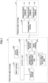
- FIG. 1 illustrates a configuration of a drive assisting system according to an embodiment.
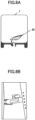
- the drive assisting system illustrated in FIG. 1 is configured to assist in driving of a tractor vehicle (generally tractor) 2 configured to pull a trailer 1 such as a camping trailer and the like illustrated in FIG. 2A and FIG. 2B .
- a tractor vehicle generally tractor
- trailer 1 such as a camping trailer and the like illustrated in FIG. 2A and FIG. 2B .
- the drive assisting system includes a trailer-side system 11 mounted on the trailer 1, and a tractor-side system 21 mounted on the tractor 2.
- the trailer-side system 11 in this embodiment includes three cameras including a trailer right camera 111, a trailer rear camera 112, and a trailer left camera 113, and a transmitting device 114 configured to wirelessly transmit images captured by the cameras to the tractor-side system 21.
- the tractor-side system 21 includes an input device 211, a state sensor 212 configured to detect various states of the tractor 2 such as the forward/reverse travelling state of the tractor 2, the steered angle of the tractor 2, and the like, a display device 213, a rear camera 214, a receiving device 215 configured to receive images wirelessly transmitted from the transmitting device 114 of the trailer-side system 11, a hitch angle detecting unit or system 216 configured to detect a hitch angle of the trailer 1 using an image captured by the rear camera 214, an assistance information generating unit 217 configured to generate various assistance information for assisting in driving of the tractor 2 using images captured by the trailer right camera 111, the trailer rear camera 112, and the trailer left camera 113, received by the receiving device 215, an image captured by the rear camera 214, the hitch angle detected by the hitch angle detecting unit 216, and the like, and to display the assistance information on the display device 213, and a control unit 218 configured to control each of the units described above.
- a state sensor 212 configured to detect
- the hitch angle detecting unit 216 may be computer-implemented with respective computer-implemented sub-units in hardware and/or software, such as calculators as described herein.
- the images captured by the trailer right camera 111, the trailer rear camera 112, and the trailer left camera 113 may be transmitted from the trailer-side system 11 to the tractor-side system 21 by wired transmission.
- the transmitting device 114 and the receiving device 215 are omitted, and the images captured by the trailer right camera 111, the trailer rear camera 112, and the trailer left camera 113 are directly transmitted to the assistance information generating unit 217.
- the trailer right camera 111 of the trailer-side system 11 captures an image of the rear view from the front end of the right surface of the trailer 1
- the trailer rear camera 112 captures an image of the rear view from the left-right direction center of the rear portion of the trailer 1
- the trailer left camera 113 captures an image of the rear view from the front end of the left surface of the trailer 1.
- the rear camera 214 of the tractor-side system 21 captures a wide-angle image of the rear view from the left-right direction center of the rear portion of the tractor 2.
- the image capturing range of the rear camera 214 is set such that a captured image includes: a rear end portion of the tractor 2 such as the rear bumper of the tractor 2 and the like; and a front end portion of the trailer 1 such as the front bumper of the trailer 1, the front ends of the chassis and the body of the trailer 1, and the like.
- a drawbar 12 coupling with the chassis extends from a lower portion of the front end of the trailer 1 to ahead of the trailer 1.
- a coupler situated on the front end of the drawbar 12 being swingably engaged with a hitch ball situated on the rear end of a hitch member 22 extending to behind the tractor 2 from a lower portion of the rear end of the tractor 2, the trailer 1 is coupled to the tractor 2.
- the trailer 1 can swing with respect to the tractor 2 about the center axis of the coupler and the hitch ball.
- the angle of the swinging denoted by ⁇ in the figures, is the hitch angle of the trailer 1.
- the hitch angle detecting unit or system 216 extracts a portion including the image of the rear end portion of the tractor 2 and the image of the front end portion of the trailer 1 from an image captured by the rear camera 214, and, by image recognition, recognizes a line extending in the left-right direction of the tractor 2 such as the line representing the rear edge of the tractor 2, and a line extending in the left-right direction of the trailer 1 such as the line representing the front edge of the trailer 1, the lines being reflected in the extracted image.
- the hitch angle detecting unit 216 calculates a first straight line, with which the recognized line extending in the left-right direction of the tractor 2 is the best approximated, as a straight line parallel with the left-right direction of the tractor 2, and a second straight line, with which the recognized line extending in the left-right direction of the trailer 1 is the best approximated, as a straight line parallel with the left-right direction of the trailer 1.
- the hitch angle detecting unit 216 calculates a relative angle of the second straight line with respect to the first straight line as the hitch angle ⁇ of the trailer 1.
- detection of the hitch angle is performed as follows, for example.
- the hitch angle detecting unit 216 extracts a portion including an image 410 of the rear bumper of the tractor 2 and an image 420 of the front bumper of the trailer 1 as illustrated in FIG. 4B from an image captured by the rear camera 214.
- the hitch angle detecting unit 216 performs edge detection in the extracted images illustrated in FIG. 4B , and extracts an edge 411 corresponding to the rear edge of the rear bumper of the tractor 2 and an edge 421 corresponding to the front edge of the front bumper of the trailer 1 as illustrated in FIG. 4C from among detected edges based on the positions, directions, and the like of the edges.
- the hitch angle detecting unit 216 calculates a straight line 412, with which the edge 411 corresponding to the rear edge of the rear bumper is the best approximated, as a straight line parallel with the left-right direction of the tractor 2, and calculates a straight line 422, with which the edge 421 corresponding to the front edge of the front bumper of the trailer 1 is the best approximated, as a straight line parallel with the left-right direction of the trailer 1, as illustrated in FIG. 4D .
- the hitch angle detecting unit 216 calculates a relative angle of the straight line 422 with respect to the straight line 412, as the hitch angle ⁇ of the trailer 1, where the relative angle is expressed as 82 - ⁇ 1 where ⁇ 1 represents the angle of the straight line 412 and 82 represents the angle of the straight line 422 as illustrated.
- the hitch angle detecting unit 216 extracts a portion including an image 410 of the rear bumper of the tractor 2 and an image 420 of the front bumper of the trailer 1 as illustrated in FIG. 5B from an image captured by the rear camera 214.
- the hitch angle detecting unit 216 performs edge detection in the extracted images illustrated in FIG. 5B , and extracts an edge 411 corresponding to the rear edge of the rear bumper of the tractor 2 and an edge 421 corresponding to the front edge of the front bumper of the trailer 1 as illustrated in FIG. 5C from among detected edges based on the positions, directions, and the like of the edges.
- the hitch angle detecting unit 216 calculates a straight line 412, with which the edge 411 corresponding to the rear edge of the rear bumper is the best approximated, as a straight line parallel with the left-right direction of the tractor 2, and calculates a straight line 422, with which the edge 421 corresponding to the front edge of the front bumper of the trailer 1 is the best approximated, as a straight line parallel with the left-right direction of the trailer 1, as illustrated in FIG. 5D .
- the hitch angle detecting unit 216 calculates a relative angle of the straight line 422 with respect to the straight line 412, as the hitch angle ⁇ of the trailer 1, where the relative angle is expressed as ⁇ 2 - ⁇ 1 where ⁇ 1 represents the angle of the straight line 412 and ⁇ 2 represents the angle of the straight line 422 as illustrated.
- the position at which the image of the rear bumper appears in the image captured by the rear camera 214 does not change for a period of time in which the conditions (position, direction, and angular field of view) of the rear camera 214 are fixed.
- the straight line 412 with which the edge 411 corresponding to the rear edge of the rear bumper is the best approximated, may be calculated based on the image captured by the rear camera 214 only for a first calculation of the period, and the hitch angle ⁇ may be calculated using the straight line 412 calculated for the first calculation of the period for each time calculating the hitch angle ⁇ .
- the angle of the left-right direction of the tractor 2 in the image captured by the rear camera 214 may be calculated previously and set fixedly, and the hitch angle ⁇ may be calculated with the set angle substituted for the angle ⁇ 1 of the straight line 412 at each time to calculate the hitch angle ⁇ .
- the assistance information generating unit 217 performs, for example, a process including calculating a relative positional relationship between the tractor 2 and the trailer 1 based on the hitch angle ⁇ detected by the hitch angle detecting unit 216 when the tractor 2 is reversing, calculating a movement trajectory of the trailer 1 predictable in a case where the tractor 2 continues to reverse without change in course based on the calculated positional relationship, and displaying the calculated movement trajectory on the display device 213 while overlaying it on images captured by the trailer right camera 111, the trailer rear camera 112, and the trailer left camera 113, a process including predicting a collision between the tractor 2 and the trailer 1 based on the hitch angle ⁇ detected by the hitch angle detecting unit 216 and a steered angle of the tractor 2 detected by the state sensor 212 when the tractor 2 is reversing, and displaying a guidance for avoiding the collision on the display device 213, a process including synthesizing images captured by the rear camera
- the hitch angle detecting unit 216 calculates the hitch angle by calculating the left-right direction of the trailer 1 based on a line representing the front edge of the trailer 1 that is recognized from an image captured by the rear camera 214.
- a marker may be pasted on a position on the trailer 1 that is image-captured by the rear camera 214 such that the marker indicates the left-right direction of the trailer 1, and the hitch angle detecting unit 216 may calculate the hitch angle by recognizing the marker from an image captured by the rear camera 214 and calculating the left-right direction of the trailer 1 based on the recognized marker.
- the hitch angle detecting unit 216 calculates the hitch angle by calculating the left-right direction of the tractor 2 based on a line representing the rear edge of the tractor 2 that is recognized from an image captured by the rear camera 214.
- a marker may be pasted on a position on the tractor 2 that is image-captured by the rear camera 214 such that the marker indicates the left-right direction of the tractor 2, and the hitch angle detecting unit 216 may calculate the hitch angle by recognizing the marker from an image captured by the rear camera 214 and calculating the left-right direction of the tractor 2 based on the recognized marker.
- a straight line-shaped marker 43 is pasted on the front surface of the trailer 1 illustrated in FIG. 6 such that the marker 43 is parallel with the left-right direction of the trailer 1 as illustrated in FIG. 7A .
- an edge 411 of the image of the rear bumper of the tractor 2 and a region 431 of the image of the marker 43 are recognized as illustrated in FIG. 7C from an image captured by the rear camera 214 illustrated in FIG. 7B .
- a straight line 412 with which the edge 411 of the image of the rear bumper is the best approximated, and a straight line 432, with which the longer dimension of the region 431 of the image of the marker 43 is parallel, are calculated as illustrated in FIG. 7D .
- the relative angle of the straight line 432 with respect to the straight line 412 is calculated as the hitch angle ⁇ of the trailer 1.
- a plurality of markers 43 are pasted on the front surface of the trailer 1 illustrated in FIG. 6 such that the markers 43 are arranged side by side in the left-right direction of the trailer 1 as illustrated in FIG. 8A .
- an edge 411 of the image of the rear bumper of the tractor 2 and regions 431 of the images of the markers 43 are recognized as illustrated in FIG. 8C from an image captured by the rear camera 214 illustrated in FIG. 8B .
- a straight line 412, with which the edge 411 of the image of the rear bumper is the best approximated, and a straight line 432 that is parallel with the direction in which the regions 431 of the images of the plurality of markers 43 are arranged side by side are calculated as illustrated in FIG. 8D .
- the relative angle of the straight line 432 with respect to the straight line 412 is calculated as the hitch angle ⁇ of the trailer 1.
- the marker 43 is pasted on the rear bumper or the like of the tractor 2, and the left-right direction of the tractor 2 is calculated in the same manner as in the case of the trailer 1 described above.
Landscapes
- Engineering & Computer Science (AREA)
- Mechanical Engineering (AREA)
- Multimedia (AREA)
- Transportation (AREA)
- Physics & Mathematics (AREA)
- General Physics & Mathematics (AREA)
- Theoretical Computer Science (AREA)
- Chemical & Material Sciences (AREA)
- Combustion & Propulsion (AREA)
- Length Measuring Devices By Optical Means (AREA)
- Computer Vision & Pattern Recognition (AREA)
Abstract
Description
- The present disclosure relates to a technique of detecting a hitch angle of a trailer.
- A technique known as a technique for detecting a hitch angle of a trailer, which is a rotation angle of a trailer swing ably coupled to a hitch ball of a tractor about the axis of the hitch ball, recognizes a straight line corresponding to the center axis of a drawbar of the trailer from an image of a portion at which the tractor and the trailer are coupled, the image being captured by a camera, and detects the angle of the recognized straight line with respect to a vehicle's left-right direction center axis of the tractor, as the hitch angle of the trailer (for example,
JP 2020-1631A - A technique also known as a technique for detecting a hitch angle of a trailer measures the distances from a tractor to both the left and right ends of a trailer in the front-rear direction of the tractor using a laser range finder, and calculates a hitch angle of the trailer based on the distance between the left and right ends and the measured distances in the front-rear direction of the tractor (for example,
JP 2021-177145A - A technique also known as a technique for detecting a hitch angle of a trailer detects a hitch angle of a trailer based on the inclination of an image of a marker pasted on the upper surface of a drawbar of the trailer, the image being captured by a camera (for example,
JP 2019-199150A - A technique known as a technique for utilizing a detected hitch angle of a trailer calculates a relative positional relationship between a tractor and a trailer based on a detected hitch angle when the tractor is reversing, calculates a movement trajectory of the trailer predictable in a case of continuing to reverse the tractor without change in course based on the calculated positional relationship, and displays the calculated movement trajectory while overlaying it on an image of the rear view of the trailer captured by a camera situated on a rear portion of the trailer (for example,
JP 2016-137802A - In relation with a system configured to generate a panorama view image representing a wide view around a tractor by synthesizing images captured by three cameras situated on left and right side portions and a rear portion of a trailer and display a partial range of the generated panorama view image to a driver, a technique known as a technique for utilizing a detected hitch angle of a trailer switches the range of the panorama view image that is to be displayed in accordance with a detected hitch angle (for example, Japanese Translation of
PCT International Publication No. JP-T-2022-547068 - A technique also known as a technique for utilizing a detected hitch angle of a trailer predicts a collision between a tractor and a trailer based on a detected hitch angle and a steered angle of the tractor when the tractor is reversing, and performs a process to avoid the collision (for example,
JP 2016-81198A - Drawbars of trailers have various shapes such as a straight line shape, a Y-letter shape, and the like. Depending on the shape of the drawbar, the aforementioned technique of detecting a hitch angle based on a straight line recognized from an image of a coupled portion may not be able to detect the hitch angle correctly.
- When employing the technique of detecting a hitch angle using a laser range finder, it is necessary to furnish the tractor and the trailer with special equipment such as a marker, a laser range finder, and the like, and to calibrate each of them separately, lacking in simplicity.
- The technique of detecting a hitch angle using a marker pasted on the upper surface of a drawbar is not applicable in a case where the shape of the drawbar or the upper surface of the drawbar is not suitable for a marker to be pasted.
- Hence, an object of the present disclosure is to realize detection of a hitch angle of a trailer with a more simple and versatile configuration of a hitch angle detection system.
- The present disclosure relates to a hitch angle detection system according to the appended claims. Embodiments are disclosed in the dependent claims.
- According to an aspect, the present disclosure provides a hitch angle detection system, which is configured to detect a hitch angle of a trailer pulled by a tractor, with a camera situated on the tractor such that a front portion of the trailer is included in an image capturing range regardless of the hitch angle of the trailer, a left-right direction calculator configured to calculate a left-right direction of the trailer based on an image of a member of the trailer extending to a left and a right of the trailer, the image of the member being reflected in an image captured by the camera, and a hitch angle calculator configured to calculate a relative angle of the left-right direction of the trailer, which is calculated, with respect to a left-right direction of the tractor as the hitch angle of the trailer.
- Here, in the hitch angle detection system, the member of the trailer extending to the left and the right of the trailer may be a member forming a front edge of the trailer, and the left-right direction calculator may calculate a direction in which a straight line, with which a line representing the front edge of the trailer reflected in the image captured by the camera is approximated, extends as the left-right direction of the trailer.
- In the hitch angle detection system described above, the camera may be situated on the tractor such that a rear portion of the tractor and the front portion of the trailer are included in the image capturing range regardless of the hitch angle of the trailer, the left-right direction calculator may calculate the left-right direction of the tractor based on an image of a member of the tractor extending to a left and a right of the tractor, the image of the member of the tractor being reflected in the image captured by the camera, and the hitch angle calculator may calculate the relative angle of the left-right direction of the trailer calculated by the left-right direction calculator with respect to the left-right direction of the tractor calculated by the left-right direction calculator as the hitch angle of the trailer.
- In this case, the member of the tractor extending to the left and the right of the tractor may be a rear bumper of the tractor, and the left-right direction calculator may calculate a direction in which a straight line, with which a line representing a rear edge of the member of the tractor reflected in the image captured by the camera is approximated, extends as the left-right direction of the tractor.
- The hitch angle detection system described above can detect the hitch angle of the trailer correctly regardless of the shape of the drawbar of the trailer. Moreover, it is possible to detect the hitch angle of the trailer without furnishing the tractor and the trailer with special equipment but by using a back camera gaining widespread use for rear view confirmation in reversing, as the camera of the hitch angle detection system.
- According to a further aspect, the present disclosure provides a hitch angle detection system, which is configured to detect a hitch angle of a trailer pulled by a tractor, with a camera situated on the tractor such that a front portion of the trailer is included in an image capturing range regardless of the hitch angle of the trailer, a marker pasted on a position that is on the front portion of the trailer and is included in the image capturing range of the camera such that the marker indicates a left-right direction of the trailer, a left-right direction calculator configured to calculate the left-right direction of the trailer indicated by an image of the marker reflected in an image captured by the camera, and a hitch angle calculator configured to calculate a relative angle of the left-right direction of the trailer, which is calculated, with respect to a left-right direction of the tractor as the hitch angle of the trailer.
- With this configuration, it is possible to detect the hitch angle θ of the trailer regardless of the shape and structure of the trailer, only by pasting a marker on the trailer itself, on which it is easier to secure a suitable pasting space than on the upper surface of the drawbar and the like.
- As described above, the present disclosure can realize detection of a hitch angle of a trailer with a more simple and versatile configuration.
-
FIG. 1 is a block diagram illustrating the configuration of a drive assisting system according to an embodiment of the present disclosure; -
FIG. 2A is a view illustrating a tractor and a trailer according to an embodiment of the present disclosure; - and
FIG. 2B is a view illustrating a tractor and a trailer according to an embodiment of the present disclosure; -
FIG. 3A is a view illustrating a hitch angle to be detected according to an embodiment of the present disclosure; -
FIG. 3B is a view illustrating a hitch angle to be detected according to an embodiment of the present disclosure; -
FIG. 4A is a drawing illustrating an example in which a hitch angle is detected according to an embodiment of the present disclosure; -
FIG. 4B is a drawing illustrating an example in which a hitch angle is detected according to an embodiment of the present disclosure; -
FIG. 4C is a drawing illustrating an example in which a hitch angle is detected according to an embodiment of the present disclosure; -
FIG. 4D is a drawing illustrating an example in which a hitch angle is detected according to an embodiment of the present disclosure; -
FIG. 5A is a drawing illustrating an example in which a hitch angle is detected according to an embodiment of the present disclosure; -
FIG. 5B is a drawing illustrating an example in which a hitch angle is detected according to an embodiment of the present disclosure; -
FIG. 5C is a drawing illustrating an example in which a hitch angle is detected according to an embodiment of the present disclosure; -
FIG. 5D is a drawing illustrating an example in which a hitch angle is detected according to an embodiment of the present disclosure; -
FIG. 6 is a drawing illustrating another example in which a hitch angle is detected according to an embodiment of the present disclosure; -
FIG. 7A is a drawing illustrating another example in which a hitch angle is detected according to an embodiment of the present disclosure; -
FIG. 7B is a drawing illustrating another example in which a hitch angle is detected according to an embodiment of the present disclosure; -
FIG. 7C is a drawing illustrating another example in which a hitch angle is detected according to an embodiment of the present disclosure; -
FIG. 7D is a drawing illustrating another example in which a hitch angle is detected according to an embodiment of the present disclosure; -
FIG. 8A is a drawing illustrating another example in which a hitch angle is detected according to an embodiment of the present disclosure; -
FIG. 8B is a drawing illustrating another example in which a hitch angle is detected according to an embodiment of the present disclosure; -
FIG. 8C is a drawing illustrating another example in which a hitch angle is detected according to an embodiment of the present disclosure; and -
FIG. 8D is a drawing illustrating another example in which a hitch angle is detected according to an embodiment of the present disclosure. - Embodiments of the present disclosure will be described below.
-
FIG. 1 illustrates a configuration of a drive assisting system according to an embodiment. - Here, the drive assisting system illustrated in
FIG. 1 is configured to assist in driving of a tractor vehicle (generally tractor) 2 configured to pull atrailer 1 such as a camping trailer and the like illustrated inFIG. 2A and FIG. 2B . - Referring back to
FIG. 1 , the drive assisting system includes a trailer-side system 11 mounted on thetrailer 1, and a tractor-side system 21 mounted on thetractor 2. - The trailer-
side system 11 in this embodiment includes three cameras including a trailerright camera 111, a trailerrear camera 112, and a trailer leftcamera 113, and atransmitting device 114 configured to wirelessly transmit images captured by the cameras to the tractor-side system 21. - The tractor-
side system 21 includes aninput device 211, astate sensor 212 configured to detect various states of thetractor 2 such as the forward/reverse travelling state of thetractor 2, the steered angle of thetractor 2, and the like, adisplay device 213, arear camera 214, a receivingdevice 215 configured to receive images wirelessly transmitted from the transmittingdevice 114 of the trailer-side system 11, a hitch angle detecting unit orsystem 216 configured to detect a hitch angle of thetrailer 1 using an image captured by therear camera 214, an assistanceinformation generating unit 217 configured to generate various assistance information for assisting in driving of thetractor 2 using images captured by the trailerright camera 111, the trailerrear camera 112, and the trailer leftcamera 113, received by the receivingdevice 215, an image captured by therear camera 214, the hitch angle detected by the hitchangle detecting unit 216, and the like, and to display the assistance information on thedisplay device 213, and acontrol unit 218 configured to control each of the units described above. - Generally, at least part of the hitch
angle detecting unit 216 may be computer-implemented with respective computer-implemented sub-units in hardware and/or software, such as calculators as described herein. - The images captured by the trailer
right camera 111, the trailerrear camera 112, and the trailer leftcamera 113 may be transmitted from the trailer-side system 11 to the tractor-side system 21 by wired transmission. In this case, the transmittingdevice 114 and the receivingdevice 215 are omitted, and the images captured by the trailerright camera 111, the trailerrear camera 112, and the trailer leftcamera 113 are directly transmitted to the assistanceinformation generating unit 217. - Next, as illustrated in
FIG. 2A and FIG. 2B , the trailerright camera 111 of the trailer-side system 11 captures an image of the rear view from the front end of the right surface of thetrailer 1, the trailerrear camera 112 captures an image of the rear view from the left-right direction center of the rear portion of thetrailer 1, and the trailer leftcamera 113 captures an image of the rear view from the front end of the left surface of thetrailer 1. - The
rear camera 214 of the tractor-side system 21 captures a wide-angle image of the rear view from the left-right direction center of the rear portion of thetractor 2. Here, the image capturing range of therear camera 214 is set such that a captured image includes: a rear end portion of thetractor 2 such as the rear bumper of thetractor 2 and the like; and a front end portion of thetrailer 1 such as the front bumper of thetrailer 1, the front ends of the chassis and the body of thetrailer 1, and the like. - A
drawbar 12 coupling with the chassis extends from a lower portion of the front end of thetrailer 1 to ahead of thetrailer 1. By a coupler situated on the front end of thedrawbar 12 being swingably engaged with a hitch ball situated on the rear end of ahitch member 22 extending to behind thetractor 2 from a lower portion of the rear end of thetractor 2, thetrailer 1 is coupled to thetractor 2. - Hence, as illustrated in
FIG. 3A and FIG. 3B , thetrailer 1 can swing with respect to thetractor 2 about the center axis of the coupler and the hitch ball. The angle of the swinging, denoted by θ in the figures, is the hitch angle of thetrailer 1. - Detection of the hitch angle of the
trailer 1, which is performed by the hitchangle detecting unit 216 using an image captured by therear camera 214 will be described below. - The hitch angle detecting unit or
system 216 extracts a portion including the image of the rear end portion of thetractor 2 and the image of the front end portion of thetrailer 1 from an image captured by therear camera 214, and, by image recognition, recognizes a line extending in the left-right direction of thetractor 2 such as the line representing the rear edge of thetractor 2, and a line extending in the left-right direction of thetrailer 1 such as the line representing the front edge of thetrailer 1, the lines being reflected in the extracted image. - Then, the hitch
angle detecting unit 216 calculates a first straight line, with which the recognized line extending in the left-right direction of thetractor 2 is the best approximated, as a straight line parallel with the left-right direction of thetractor 2, and a second straight line, with which the recognized line extending in the left-right direction of thetrailer 1 is the best approximated, as a straight line parallel with the left-right direction of thetrailer 1. - Then, the hitch
angle detecting unit 216 calculates a relative angle of the second straight line with respect to the first straight line as the hitch angle θ of thetrailer 1. - That is, detection of the hitch angle is performed as follows, for example.
- In a case where the current positioning relationship between the
tractor 2 including a rear bumper and thetrailer 1 including a front bumper is as illustrated inFIG. 4A , the hitchangle detecting unit 216 extracts a portion including animage 410 of the rear bumper of thetractor 2 and animage 420 of the front bumper of thetrailer 1 as illustrated inFIG. 4B from an image captured by therear camera 214. - Then, the hitch
angle detecting unit 216 performs edge detection in the extracted images illustrated inFIG. 4B , and extracts anedge 411 corresponding to the rear edge of the rear bumper of thetractor 2 and anedge 421 corresponding to the front edge of the front bumper of thetrailer 1 as illustrated inFIG. 4C from among detected edges based on the positions, directions, and the like of the edges. - Then, by a regression analysis or the like, the hitch
angle detecting unit 216 calculates astraight line 412, with which theedge 411 corresponding to the rear edge of the rear bumper is the best approximated, as a straight line parallel with the left-right direction of thetractor 2, and calculates astraight line 422, with which theedge 421 corresponding to the front edge of the front bumper of thetrailer 1 is the best approximated, as a straight line parallel with the left-right direction of thetrailer 1, as illustrated inFIG. 4D . - Then, the hitch
angle detecting unit 216 calculates a relative angle of thestraight line 422 with respect to thestraight line 412, as the hitch angle θ of thetrailer 1, where the relative angle is expressed as 82 - θ1 where θ1 represents the angle of thestraight line 412 and 82 represents the angle of thestraight line 422 as illustrated. - Likewise, in a case where the positioning relationship between the
tractor 2 including the rear bumper and thetrailer 1 including the front bumper is as illustrated inFIG. 5A , the hitchangle detecting unit 216 extracts a portion including animage 410 of the rear bumper of thetractor 2 and animage 420 of the front bumper of thetrailer 1 as illustrated inFIG. 5B from an image captured by therear camera 214. - Then, the hitch
angle detecting unit 216 performs edge detection in the extracted images illustrated inFIG. 5B , and extracts anedge 411 corresponding to the rear edge of the rear bumper of thetractor 2 and anedge 421 corresponding to the front edge of the front bumper of thetrailer 1 as illustrated inFIG. 5C from among detected edges based on the positions, directions, and the like of the edges. - Then, by a regression analysis or the like, the hitch
angle detecting unit 216 calculates astraight line 412, with which theedge 411 corresponding to the rear edge of the rear bumper is the best approximated, as a straight line parallel with the left-right direction of thetractor 2, and calculates astraight line 422, with which theedge 421 corresponding to the front edge of the front bumper of thetrailer 1 is the best approximated, as a straight line parallel with the left-right direction of thetrailer 1, as illustrated inFIG. 5D . - Then, the hitch
angle detecting unit 216 calculates a relative angle of thestraight line 422 with respect to thestraight line 412, as the hitch angle θ of thetrailer 1, where the relative angle is expressed as θ2 - θ1 where θ1 represents the angle of thestraight line 412 and θ2 represents the angle of thestraight line 422 as illustrated. - The position at which the image of the rear bumper appears in the image captured by the
rear camera 214 does not change for a period of time in which the conditions (position, direction, and angular field of view) of therear camera 214 are fixed. Hence, in this period of time, thestraight line 412, with which theedge 411 corresponding to the rear edge of the rear bumper is the best approximated, may be calculated based on the image captured by therear camera 214 only for a first calculation of the period, and the hitch angle θ may be calculated using thestraight line 412 calculated for the first calculation of the period for each time calculating the hitch angle θ. - Alternatively, the angle of the left-right direction of the
tractor 2 in the image captured by therear camera 214 may be calculated previously and set fixedly, and the hitch angle θ may be calculated with the set angle substituted for the angle θ1 of thestraight line 412 at each time to calculate the hitch angle θ. - Referring back to
FIG. 1 , under control of the control unit 218, the assistance information generating unit 217 performs, for example, a process including calculating a relative positional relationship between the tractor 2 and the trailer 1 based on the hitch angle θ detected by the hitch angle detecting unit 216 when the tractor 2 is reversing, calculating a movement trajectory of the trailer 1 predictable in a case where the tractor 2 continues to reverse without change in course based on the calculated positional relationship, and displaying the calculated movement trajectory on the display device 213 while overlaying it on images captured by the trailer right camera 111, the trailer rear camera 112, and the trailer left camera 113, a process including predicting a collision between the tractor 2 and the trailer 1 based on the hitch angle θ detected by the hitch angle detecting unit 216 and a steered angle of the tractor 2 detected by the state sensor 212 when the tractor 2 is reversing, and displaying a guidance for avoiding the collision on the display device 213, a process including synthesizing images captured by the rear camera 214, the trailer right camera 111, the trailer rear camera 112, and the trailer left camera 113 into one image widely overlooking the view around the tractor 2 from a perspective set at the rear portion of the tractor 2 using the hitch angle θ detected by the hitch angle detecting unit 216 and displaying the resulting image on the display device 213, and the like. - Embodiments of the present disclosure have been described above.
- According to these embodiments, it is possible to correctly detect the hitch angle of the
trailer 1 regardless of the shape of thedrawbar 12 of thetrailer 1. Moreover, it is possible to detect the hitch angle of thetrailer 1 without furnishing thetractor 2 and thetrailer 1 with special equipment, by using therear camera 214 gaining widespread use for rear view confirmation in reversing. - In the embodiments described above, the hitch
angle detecting unit 216 calculates the hitch angle by calculating the left-right direction of thetrailer 1 based on a line representing the front edge of thetrailer 1 that is recognized from an image captured by therear camera 214. Here, a marker may be pasted on a position on thetrailer 1 that is image-captured by therear camera 214 such that the marker indicates the left-right direction of thetrailer 1, and the hitchangle detecting unit 216 may calculate the hitch angle by recognizing the marker from an image captured by therear camera 214 and calculating the left-right direction of thetrailer 1 based on the recognized marker. - Likewise, in the embodiments described above, the hitch
angle detecting unit 216 calculates the hitch angle by calculating the left-right direction of thetractor 2 based on a line representing the rear edge of thetractor 2 that is recognized from an image captured by therear camera 214. Here, a marker may be pasted on a position on thetractor 2 that is image-captured by therear camera 214 such that the marker indicates the left-right direction of thetractor 2, and the hitchangle detecting unit 216 may calculate the hitch angle by recognizing the marker from an image captured by therear camera 214 and calculating the left-right direction of thetractor 2 based on the recognized marker. - For example, in a case of calculating the hitch angle θ by calculating the left-right direction of the
tractor 2 in the same manner as in the embodiments described above and calculating the left-right direction of thetrailer 1 using a marker pasted on thetrailer 1, a straight line-shapedmarker 43 is pasted on the front surface of thetrailer 1 illustrated inFIG. 6 such that themarker 43 is parallel with the left-right direction of thetrailer 1 as illustrated inFIG. 7A . - Then, an
edge 411 of the image of the rear bumper of thetractor 2 and aregion 431 of the image of themarker 43 are recognized as illustrated inFIG. 7C from an image captured by therear camera 214 illustrated inFIG. 7B . - Then, a
straight line 412, with which theedge 411 of the image of the rear bumper is the best approximated, and astraight line 432, with which the longer dimension of theregion 431 of the image of themarker 43 is parallel, are calculated as illustrated inFIG. 7D . - Then, the relative angle of the
straight line 432 with respect to thestraight line 412 is calculated as the hitch angle θ of thetrailer 1. - Alternatively, in this case, for example, a plurality of
markers 43 are pasted on the front surface of thetrailer 1 illustrated inFIG. 6 such that themarkers 43 are arranged side by side in the left-right direction of thetrailer 1 as illustrated inFIG. 8A . - Then, an
edge 411 of the image of the rear bumper of thetractor 2 andregions 431 of the images of themarkers 43 are recognized as illustrated inFIG. 8C from an image captured by therear camera 214 illustrated inFIG. 8B . - Then, a
straight line 412, with which theedge 411 of the image of the rear bumper is the best approximated, and astraight line 432 that is parallel with the direction in which theregions 431 of the images of the plurality ofmarkers 43 are arranged side by side are calculated as illustrated inFIG. 8D . - Then, the relative angle of the
straight line 432 with respect to thestraight line 412 is calculated as the hitch angle θ of thetrailer 1. - In a case of calculating the left-right direction of the
tractor 2 by using amarker 43 pasted on thetractor 2, themarker 43 is pasted on the rear bumper or the like of thetractor 2, and the left-right direction of thetractor 2 is calculated in the same manner as in the case of thetrailer 1 described above. - In this way, only by pasting the marker(s) 43 on the
tractor 2 and thetrailer 1 themselves, on which it is easier to secure a relatively good pasting space than to secure one on, for example, the upper surface of thedrawbar 12 or the like, it is possible to detect the hitch angle θ of thetrailer 1 regardless of the shape and structure of the rear end of thetractor 2 and the shape and structure of the front end of thetrailer 1.
Claims (5)
- A hitch angle detection system configured to detect a hitch angle of a trailer pulled by a tractor, the hitch angle detection system comprising:a camera situated on the tractor such that a front portion of the trailer is included in an image capturing range regardless of the hitch angle of the trailer;a left-right direction calculator configured to calculate a left-right direction of the trailer based on an image of a member of the trailer extending to a left and a right of the trailer, the image of the member being reflected in an image captured by the camera; anda hitch angle calculator configured to calculate a relative angle of the left-right direction of the trailer, which is calculated, with respect to a left-right direction of the tractor as the hitch angle of the trailer.
- The hitch angle detection system according to claim 1,wherein the member of the trailer extending to the left and the right of the trailer is a member forming a front edge of the trailer, andthe left-right direction calculator is configured to calculate a direction in which a straight line, with which a line representing the front edge of the trailer reflected in the image captured by the camera is approximated, extends as the left-right direction of the trailer.
- The hitch angle detection system according to claim 1 or 2,wherein the camera is situated on the tractor such that a rear portion of the tractor and the front portion of the trailer are included in the image capturing range regardless of the hitch angle of the trailer,the left-right direction calculator is configured to calculate the left-right direction of the tractor based on an image of a member of the tractor extending to a left and right of the tractor, the image of the member of the tractor being reflected in the image captured by the camera, andthe hitch angle calculator is configured to calculate the relative angle of the left-right direction of the trailer calculated by the left-right direction calculator with respect to the left-right direction of the tractor calculated by the left-right direction calculator as the hitch angle of the trailer.
- The hitch angle detection system according to claim 3,wherein the member of the tractor extending to the left and the right of the tractor is a member forming a rear edge of the tractor, andthe left-right direction calculator is configured to calculate a direction in which a straight line, with which a line representing the rear edge of the tractor reflected in the image captured by the camera is approximated, extends as the left-right direction of the tractor.
- A hitch angle detection system configured to detect a hitch angle of a trailer pulled by a tractor, the hitch angle detection system comprising:a camera situated on the tractor such that a front portion of the trailer is included in an image capturing range regardless of the hitch angle of the trailer;a marker pasted on a position that is on the front portion of the trailer and is included in the image capturing range of the camera such that the marker indicates a left-right direction of the trailer;a left-right direction calculator configured to calculate the left-right direction of the trailer indicated by an image of the marker, the image of the marker being reflected in an image captured by the camera; anda hitch angle calculator configured to calculate a relative angle of the left-right direction of the trailer, which is calculated, with respect to a left-right direction of the tractor as the hitch angle of the trailer.
Applications Claiming Priority (1)
| Application Number | Priority Date | Filing Date | Title |
|---|---|---|---|
| JP2023083260A JP2024166869A (en) | 2023-05-19 | 2023-05-19 | Hitch angle calculation system |
Publications (1)
| Publication Number | Publication Date |
|---|---|
| EP4464523A1 true EP4464523A1 (en) | 2024-11-20 |
Family
ID=91129730
Family Applications (1)
| Application Number | Title | Priority Date | Filing Date |
|---|---|---|---|
| EP24176191.5A Pending EP4464523A1 (en) | 2023-05-19 | 2024-05-16 | Hitch angle detection system |
Country Status (4)
| Country | Link |
|---|---|
| US (1) | US20240383403A1 (en) |
| EP (1) | EP4464523A1 (en) |
| JP (1) | JP2024166869A (en) |
| CN (1) | CN118991309A (en) |
Citations (12)
| Publication number | Priority date | Publication date | Assignee | Title |
|---|---|---|---|---|
| JP2002068032A (en) * | 2000-08-24 | 2002-03-08 | Isuzu Motors Ltd | Trailer connection angle detection device |
| JP2003148938A (en) * | 2001-11-15 | 2003-05-21 | Hino Motors Ltd | Connection angle detector |
| JP2016081198A (en) | 2014-10-14 | 2016-05-16 | アルパイン株式会社 | Driving assist system |
| JP2016137802A (en) | 2015-01-27 | 2016-08-04 | 日野自動車株式会社 | Connecting angle acquisition device for connected vehicle and driving support system for connected vehicle |
| EP3291137A1 (en) * | 2016-09-06 | 2018-03-07 | Delphi Technologies, Inc. | Camera based trailer detection and tracking |
| DE102016117284A1 (en) * | 2016-09-14 | 2018-03-15 | Connaught Electronics Ltd. | Determining a position of a trailer hitch |
| DE102017130121A1 (en) * | 2017-12-15 | 2019-06-19 | Connaught Electronics Ltd. | Display device for displaying a current hitch angle of a team on a hitch angle indicator and method |
| JP2019199150A (en) | 2018-05-16 | 2019-11-21 | クラリオン株式会社 | Towing support device |
| JP2020001631A (en) | 2018-06-29 | 2020-01-09 | アイシン精機株式会社 | Traction support device |
| JP2021177145A (en) | 2020-05-08 | 2021-11-11 | 日野自動車株式会社 | Control device, control system, and derivation method |
| DE102022003080A1 (en) * | 2022-08-23 | 2022-11-03 | Mercedes-Benz Group AG | Method for operating a trailer maneuvering assistance system and vehicle |
| WO2023066610A1 (en) * | 2021-10-22 | 2023-04-27 | Continental Automotive Gmbh | Method for determining the angular position of a complex vehicle with two axes of rotation, and system configured to implement such a method |
Family Cites Families (3)
| Publication number | Priority date | Publication date | Assignee | Title |
|---|---|---|---|---|
| US20030234512A1 (en) * | 2002-06-20 | 2003-12-25 | Holub David G. | Trailer hitch video alignment system |
| US10701299B2 (en) * | 2014-08-18 | 2020-06-30 | Jaguar Land Rover Limited | Display system and method |
| JP7785607B2 (en) * | 2022-04-28 | 2025-12-15 | 株式会社ジェイテクト | Relative angle detection device for articulated vehicles |
-
2023
- 2023-05-19 JP JP2023083260A patent/JP2024166869A/en active Pending
-
2024
- 2024-05-02 US US18/653,379 patent/US20240383403A1/en active Pending
- 2024-05-16 EP EP24176191.5A patent/EP4464523A1/en active Pending
- 2024-05-17 CN CN202410614605.3A patent/CN118991309A/en active Pending
Patent Citations (12)
| Publication number | Priority date | Publication date | Assignee | Title |
|---|---|---|---|---|
| JP2002068032A (en) * | 2000-08-24 | 2002-03-08 | Isuzu Motors Ltd | Trailer connection angle detection device |
| JP2003148938A (en) * | 2001-11-15 | 2003-05-21 | Hino Motors Ltd | Connection angle detector |
| JP2016081198A (en) | 2014-10-14 | 2016-05-16 | アルパイン株式会社 | Driving assist system |
| JP2016137802A (en) | 2015-01-27 | 2016-08-04 | 日野自動車株式会社 | Connecting angle acquisition device for connected vehicle and driving support system for connected vehicle |
| EP3291137A1 (en) * | 2016-09-06 | 2018-03-07 | Delphi Technologies, Inc. | Camera based trailer detection and tracking |
| DE102016117284A1 (en) * | 2016-09-14 | 2018-03-15 | Connaught Electronics Ltd. | Determining a position of a trailer hitch |
| DE102017130121A1 (en) * | 2017-12-15 | 2019-06-19 | Connaught Electronics Ltd. | Display device for displaying a current hitch angle of a team on a hitch angle indicator and method |
| JP2019199150A (en) | 2018-05-16 | 2019-11-21 | クラリオン株式会社 | Towing support device |
| JP2020001631A (en) | 2018-06-29 | 2020-01-09 | アイシン精機株式会社 | Traction support device |
| JP2021177145A (en) | 2020-05-08 | 2021-11-11 | 日野自動車株式会社 | Control device, control system, and derivation method |
| WO2023066610A1 (en) * | 2021-10-22 | 2023-04-27 | Continental Automotive Gmbh | Method for determining the angular position of a complex vehicle with two axes of rotation, and system configured to implement such a method |
| DE102022003080A1 (en) * | 2022-08-23 | 2022-11-03 | Mercedes-Benz Group AG | Method for operating a trailer maneuvering assistance system and vehicle |
Also Published As
| Publication number | Publication date |
|---|---|
| JP2024166869A (en) | 2024-11-29 |
| CN118991309A (en) | 2024-11-22 |
| US20240383403A1 (en) | 2024-11-21 |
Similar Documents
| Publication | Publication Date | Title |
|---|---|---|
| US12552456B2 (en) | Vehicular trailering assist system | |
| US10863335B2 (en) | Vehicle trailer angle detection system using short range communication devices | |
| US20250118087A1 (en) | Vehicular trailering assist system | |
| EP2988958B1 (en) | Vehicle hitch assistance system | |
| US10875574B2 (en) | Method for operating a trailer maneuvering assistance system of a transportation vehicle and trailer maneuvering assistance system for a transportation vehicle | |
| EP1251025B1 (en) | Driving aiding system | |
| US9971943B2 (en) | Vehicle trailer angle detection system and method | |
| US6765607B2 (en) | Driving aiding system | |
| JP3494434B2 (en) | Parking assistance device | |
| EP3140725B1 (en) | Dynamic camera view to aid with trailer attachment | |
| US6958770B2 (en) | Driving assistance apparatus | |
| US11443413B2 (en) | Vehicle camera system for outside view and trailer aid | |
| US20180061102A1 (en) | Drive assist device and drive assist method | |
| JP2005112004A (en) | Vehicle retraction support apparatus and method | |
| CN113247009B (en) | Method and device for determining the size of a trailer in a motor vehicle | |
| JP6697281B2 (en) | Object detection device | |
| JP2024145479A (en) | Driving Support Devices | |
| CN201402131Y (en) | Handling aids for split vehicles | |
| JP3960153B2 (en) | Vehicle periphery monitoring device | |
| EP4464523A1 (en) | Hitch angle detection system | |
| US20200238912A1 (en) | Backup camera system for a vehicle having a trailer hitch | |
| US20240391388A1 (en) | Rear view image display system | |
| US20250196771A1 (en) | Control device, control method, and storage medium storing control program | |
| EP4467393A1 (en) | Rear view image display system | |
| CN114228704B (en) | Obstacle detection control system and detection method thereof |
Legal Events
| Date | Code | Title | Description |
|---|---|---|---|
| PUAI | Public reference made under article 153(3) epc to a published international application that has entered the european phase |
Free format text: ORIGINAL CODE: 0009012 |
|
| STAA | Information on the status of an ep patent application or granted ep patent |
Free format text: STATUS: THE APPLICATION HAS BEEN PUBLISHED |
|
| AK | Designated contracting states |
Kind code of ref document: A1 Designated state(s): AL AT BE BG CH CY CZ DE DK EE ES FI FR GB GR HR HU IE IS IT LI LT LU LV MC ME MK MT NL NO PL PT RO RS SE SI SK SM TR |
|
| STAA | Information on the status of an ep patent application or granted ep patent |
Free format text: STATUS: REQUEST FOR EXAMINATION WAS MADE |
|
| 17P | Request for examination filed |
Effective date: 20250509 |
|
| STAA | Information on the status of an ep patent application or granted ep patent |
Free format text: STATUS: EXAMINATION IS IN PROGRESS |
|
| 17Q | First examination report despatched |
Effective date: 20260205 |